EP3350857B1 - Vorlithiiertes, kohlenstoffbeschichtetes anodenaktivmaterial - Google Patents
Vorlithiiertes, kohlenstoffbeschichtetes anodenaktivmaterial Download PDFInfo
- Publication number
- EP3350857B1 EP3350857B1 EP16763744.6A EP16763744A EP3350857B1 EP 3350857 B1 EP3350857 B1 EP 3350857B1 EP 16763744 A EP16763744 A EP 16763744A EP 3350857 B1 EP3350857 B1 EP 3350857B1
- Authority
- EP
- European Patent Office
- Prior art keywords
- carbon
- active material
- anode active
- lithium
- lithiated
- Prior art date
- Legal status (The legal status is an assumption and is not a legal conclusion. Google has not performed a legal analysis and makes no representation as to the accuracy of the status listed.)
- Active
Links
Images

Classifications
-
- H—ELECTRICITY
- H01—ELECTRIC ELEMENTS
- H01M—PROCESSES OR MEANS, e.g. BATTERIES, FOR THE DIRECT CONVERSION OF CHEMICAL ENERGY INTO ELECTRICAL ENERGY
- H01M4/00—Electrodes
- H01M4/02—Electrodes composed of, or comprising, active material
- H01M4/36—Selection of substances as active materials, active masses, active liquids
- H01M4/362—Composites
- H01M4/366—Composites as layered products
-
- C—CHEMISTRY; METALLURGY
- C23—COATING METALLIC MATERIAL; COATING MATERIAL WITH METALLIC MATERIAL; CHEMICAL SURFACE TREATMENT; DIFFUSION TREATMENT OF METALLIC MATERIAL; COATING BY VACUUM EVAPORATION, BY SPUTTERING, BY ION IMPLANTATION OR BY CHEMICAL VAPOUR DEPOSITION, IN GENERAL; INHIBITING CORROSION OF METALLIC MATERIAL OR INCRUSTATION IN GENERAL
- C23C—COATING METALLIC MATERIAL; COATING MATERIAL WITH METALLIC MATERIAL; SURFACE TREATMENT OF METALLIC MATERIAL BY DIFFUSION INTO THE SURFACE, BY CHEMICAL CONVERSION OR SUBSTITUTION; COATING BY VACUUM EVAPORATION, BY SPUTTERING, BY ION IMPLANTATION OR BY CHEMICAL VAPOUR DEPOSITION, IN GENERAL
- C23C16/00—Chemical coating by decomposition of gaseous compounds, without leaving reaction products of surface material in the coating, i.e. chemical vapour deposition [CVD] processes
- C23C16/06—Chemical coating by decomposition of gaseous compounds, without leaving reaction products of surface material in the coating, i.e. chemical vapour deposition [CVD] processes characterised by the deposition of metallic material
-
- C—CHEMISTRY; METALLURGY
- C23—COATING METALLIC MATERIAL; COATING MATERIAL WITH METALLIC MATERIAL; CHEMICAL SURFACE TREATMENT; DIFFUSION TREATMENT OF METALLIC MATERIAL; COATING BY VACUUM EVAPORATION, BY SPUTTERING, BY ION IMPLANTATION OR BY CHEMICAL VAPOUR DEPOSITION, IN GENERAL; INHIBITING CORROSION OF METALLIC MATERIAL OR INCRUSTATION IN GENERAL
- C23C—COATING METALLIC MATERIAL; COATING MATERIAL WITH METALLIC MATERIAL; SURFACE TREATMENT OF METALLIC MATERIAL BY DIFFUSION INTO THE SURFACE, BY CHEMICAL CONVERSION OR SUBSTITUTION; COATING BY VACUUM EVAPORATION, BY SPUTTERING, BY ION IMPLANTATION OR BY CHEMICAL VAPOUR DEPOSITION, IN GENERAL
- C23C16/00—Chemical coating by decomposition of gaseous compounds, without leaving reaction products of surface material in the coating, i.e. chemical vapour deposition [CVD] processes
- C23C16/22—Chemical coating by decomposition of gaseous compounds, without leaving reaction products of surface material in the coating, i.e. chemical vapour deposition [CVD] processes characterised by the deposition of inorganic material, other than metallic material
- C23C16/26—Deposition of carbon only
-
- C—CHEMISTRY; METALLURGY
- C23—COATING METALLIC MATERIAL; COATING MATERIAL WITH METALLIC MATERIAL; CHEMICAL SURFACE TREATMENT; DIFFUSION TREATMENT OF METALLIC MATERIAL; COATING BY VACUUM EVAPORATION, BY SPUTTERING, BY ION IMPLANTATION OR BY CHEMICAL VAPOUR DEPOSITION, IN GENERAL; INHIBITING CORROSION OF METALLIC MATERIAL OR INCRUSTATION IN GENERAL
- C23C—COATING METALLIC MATERIAL; COATING MATERIAL WITH METALLIC MATERIAL; SURFACE TREATMENT OF METALLIC MATERIAL BY DIFFUSION INTO THE SURFACE, BY CHEMICAL CONVERSION OR SUBSTITUTION; COATING BY VACUUM EVAPORATION, BY SPUTTERING, BY ION IMPLANTATION OR BY CHEMICAL VAPOUR DEPOSITION, IN GENERAL
- C23C16/00—Chemical coating by decomposition of gaseous compounds, without leaving reaction products of surface material in the coating, i.e. chemical vapour deposition [CVD] processes
- C23C16/44—Chemical coating by decomposition of gaseous compounds, without leaving reaction products of surface material in the coating, i.e. chemical vapour deposition [CVD] processes characterised by the method of coating
- C23C16/4417—Methods specially adapted for coating powder
-
- H—ELECTRICITY
- H01—ELECTRIC ELEMENTS
- H01M—PROCESSES OR MEANS, e.g. BATTERIES, FOR THE DIRECT CONVERSION OF CHEMICAL ENERGY INTO ELECTRICAL ENERGY
- H01M10/00—Secondary cells; Manufacture thereof
- H01M10/05—Accumulators with non-aqueous electrolyte
- H01M10/052—Li-accumulators
- H01M10/0525—Rocking-chair batteries, i.e. batteries with lithium insertion or intercalation in both electrodes; Lithium-ion batteries
-
- H—ELECTRICITY
- H01—ELECTRIC ELEMENTS
- H01M—PROCESSES OR MEANS, e.g. BATTERIES, FOR THE DIRECT CONVERSION OF CHEMICAL ENERGY INTO ELECTRICAL ENERGY
- H01M4/00—Electrodes
- H01M4/02—Electrodes composed of, or comprising, active material
- H01M4/36—Selection of substances as active materials, active masses, active liquids
- H01M4/38—Selection of substances as active materials, active masses, active liquids of elements or alloys
- H01M4/386—Silicon or alloys based on silicon
-
- H—ELECTRICITY
- H01—ELECTRIC ELEMENTS
- H01M—PROCESSES OR MEANS, e.g. BATTERIES, FOR THE DIRECT CONVERSION OF CHEMICAL ENERGY INTO ELECTRICAL ENERGY
- H01M4/00—Electrodes
- H01M4/02—Electrodes composed of, or comprising, active material
- H01M4/36—Selection of substances as active materials, active masses, active liquids
- H01M4/58—Selection of substances as active materials, active masses, active liquids of inorganic compounds other than oxides or hydroxides, e.g. sulfides, selenides, tellurides, halogenides or LiCoFy; of polyanionic structures, e.g. phosphates, silicates or borates
- H01M4/583—Carbonaceous material, e.g. graphite-intercalation compounds or CFx
- H01M4/587—Carbonaceous material, e.g. graphite-intercalation compounds or CFx for inserting or intercalating light metals
-
- H—ELECTRICITY
- H01—ELECTRIC ELEMENTS
- H01M—PROCESSES OR MEANS, e.g. BATTERIES, FOR THE DIRECT CONVERSION OF CHEMICAL ENERGY INTO ELECTRICAL ENERGY
- H01M10/00—Secondary cells; Manufacture thereof
- H01M10/05—Accumulators with non-aqueous electrolyte
- H01M10/052—Li-accumulators
-
- Y—GENERAL TAGGING OF NEW TECHNOLOGICAL DEVELOPMENTS; GENERAL TAGGING OF CROSS-SECTIONAL TECHNOLOGIES SPANNING OVER SEVERAL SECTIONS OF THE IPC; TECHNICAL SUBJECTS COVERED BY FORMER USPC CROSS-REFERENCE ART COLLECTIONS [XRACs] AND DIGESTS
- Y02—TECHNOLOGIES OR APPLICATIONS FOR MITIGATION OR ADAPTATION AGAINST CLIMATE CHANGE
- Y02E—REDUCTION OF GREENHOUSE GAS [GHG] EMISSIONS, RELATED TO ENERGY GENERATION, TRANSMISSION OR DISTRIBUTION
- Y02E60/00—Enabling technologies; Technologies with a potential or indirect contribution to GHG emissions mitigation
- Y02E60/10—Energy storage using batteries
Definitions
- the present invention relates to a method for producing an anode active material for a lithium cell, an anode active material, and a lithium cell
- Silicon is one of the most promising anode materials for the next generation of lithium-ion batteries, as silicon offers a very high capacity, which is, for example, at 3670 mA / g at around 0.4 V versus lithium and around ten times higher than the capacity can be made of graphite.
- SEI layer Solid Electrolyte Interface
- an SEI layer can be formed from electrolyte decomposition products.
- the SEI layer is unstable and constantly breaks up with progressive volume expansion and exposes new reaction surface to the electrolyte, which leads to constant SEI formation and finally to the formation of an inhomogeneous layer with many cracks and other defects, which the layer during of the following cycles prone to breakage.
- the pamphlet US 2010/0173198 A1 relates to a secondary lithium-ion battery with a prelithiated anode.
- the pamphlet US 2007/0099084 A1 relates to a high-capacitance electrode and manufacturing method therefor.
- the pamphlet US 2012/0100438 A1 relates to composites which contain a highly capacitive, porous active material bounded by a shell.
- the invention relates to a method for producing an anode active material for a lithium cell.
- a lithium cell can in particular be understood to mean an electrochemical cell, for example a battery cell, for example a secondary or primary battery cell, in whose electrochemical reaction lithium is involved.
- a lithium cell can be a lithium-ion cell or a lithium-sulfur cell or a lithium-oxygen cell, for example a lithium-air cell.
- an anode active material is lithiated and coated with carbon.
- an anode active material can (initially) be lithiated and the lithiated anode active material (then) coated with carbon.
- the anode active material comprises silicon.
- the anode material can be formed from silicon.
- the anode active material can for example be in the form of anode active material particles.
- the anode active material particles can comprise silicon or be formed therefrom.
- the anode active material particle may be in the form of silicon particles.
- anode active material particles, for example silicon particles can be coated with carbon.
- the anode active material for example the anode active material particles, for example the silicon particles, so that the lithiated (and thus expanded) anode active material, for example the anode active material particles, for example the silicon particles, are coated with the carbon .
- anode active material for example lithiated (and thus expanded) anode active material particles, for example silicon particles
- an anode active material can be provided in this way, which in particular up to its maximum volume, for example up to approximately four times its volume, for example 3.75 times or more its volume, in the case of completely lithiated silicon (Li max Si, for example with ( ⁇ ) 3.75 Li / Si, for example Li 3.75 Si or Li 4.4 Si), can be expanded and has a carbon surface coating.
- anode active material particles for example silicon particles
- anode active material particles can thus advantageously be provided which in particular up to their maximum volume, for example up to about four times their volume, for example 3.75 times or more their volume, in the case of completely lithiated silicon (Li max Si), can be expanded and have a carbon surface coating.
- the Carbon surface coating advantageously serve as a protective layer and electrolyte barrier and also impart electrical conductivity.
- anode active material for example on the anode active material particles, for example silicon particles, which have a certain mechanical stability and, for example, both during lithium alloy formation-related expansion and during lithium alloy regression-related shrinkage of the anode active material, for example the anode active material particles
- Example silicon particles can remain mechanically stable, in particular without - in contrast to an SEI layer formed on untreated silicon, for example conventional silicon particles - breaking during expansion and / or without - in particular also in contrast to one on prelithiated silicon, for example prelithiated silicon Silicon particles, formed SEI layer - to collapse when shrinking.
- the method can advantageously provide carbon-coated and thereby mechanically stabilized, prelithiated anode active material, for example silicon.
- An SEI layer can advantageously already be formed on the carbon coating during the first cycling cycle - for example when the cell voltage of a cell, for example a carbonate-containing cell, falls below 0.8 V, which can advantageously remain stable in the following cycles.
- the SEI layer on the carbon coating can in particular remain stable, since the carbon undergoes only minimal or even no expansion in volume during lithiation, for example in the case of a completely lithiated carbon coating.
- the anode active material is lithiated by means of chemical vapor deposition.
- chemical A homogeneous lithiation of the anode active material can advantageously be achieved by vapor deposition.
- the process control can also be simplified.
- a lithium precursor in particular be used.
- the lithium precursor comprises or is at least one lithiated hydrocarbon, for example at least one lithiated alkyne, for example lithiated acetylene, and / or at least one lithiated aromatic hydrocarbon, for example lithiated toluene.
- lithiated hydrocarbon for example at least one lithiated alkyne, for example lithiated acetylene, and / or at least one lithiated aromatic hydrocarbon, for example lithiated toluene.
- the anode active material for example lithiated, is coated with carbon by means of chemical vapor deposition.
- a carbon coating formed by means of chemical vapor deposition can advantageously have a particularly high homogeneity and / or mechanical stability and remain mechanically stable both during lithium alloy formation-related expansion and during lithium alloy regression-related shrinkage of the anode active material, in particular the anode active material particles.
- the thickness and / or morphology of the coating for example in the form of a film, can advantageously be set in a targeted manner and a large selection of carbon precursors can be used, which, for example, with regard to setting a desired morphology and / or conductivity of the Coating can be selected.
- a carbon precursor in particular be used.
- the carbon precursor comprises or is at least one hydrocarbon, for example at least one alkyne, for example acetylene, and / or at least one aromatic hydrocarbon, for example toluene.
- the lithiation and coating with carbon takes place according to the invention step by step, by alternately repeated, for example, partial lithiation of the anode active material and coating of the partially lithiated anode active material with carbon, for example until complete lithiation (and thus maximum expansion) is achieved.
- the lithiation and coating with carbon are repeated alternately.
- the carbon coating can advantageously be lithiated on the one hand and compressed by the volume expansion occurring during lithiation on the other, which in turn can advantageously increase the stability of the carbon coating.
- the anode active material is partially lithiated in the method.
- the partially lithiated anode active material can be coated with carbon.
- the anode active material can be (first) partially lithiated and (then) the partially lithiated anode active material coated with carbon.
- the partially lithiated, carbon-coated anode material is (then) further partially lithiated.
- the further partially lithiated, carbon-coated anode active material is (then) coated again with carbon.
- the coating can advantageously be further stabilized by repeated carbon coating.
- anode active material particles for example silicon particles
- anode active material particles can (initially) be partially lithiated and (then) the partially lithiated anode active material particles, for example silicon particles, can be coated with carbon.
- the partially lithiated, carbon-coated anode material particles, for example silicon particles can (then) be further partially lithiated, for example.
- the further partially lithiated, carbon-coated anode active material particles, for example silicon particles can (then) be coated again with carbon, for example.
- the partial lithiation and coating with carbon are repeated alternately.
- the, in particular partial, lithiation and coating with carbon are repeated alternately at least twice, in particular at least ten times, for example at least twenty times. In this way, a particularly stable carbon surface coating can advantageously be achieved.
- the, in particular partially, lithiation and coating with carbon are repeated alternately until an average layer thickness of the carbon coating in a range from 50 nm to 0.5 ⁇ m is reached.
- an average layer thickness of the carbon coating in a range from 50 nm to 0.5 ⁇ m is reached.
- the lithiation, in particular partially, and coating with carbon until a complete one is achieved Lithiation of the anode active material is repeated alternately.
- a particularly stable carbon surface coating can advantageously be achieved, in particular which is stable even in the most expanded state of the anode active material, for example the anode active material particles, for example silicon particles.
- the anode active material can be alternately partially lithiated and the partially lithiated anode active material coated with carbon until a complete lithiation is achieved.
- the anode active material particles for example silicon particles
- the anode active material particles can alternately be partially lithiated and the partially lithiated anode active material particles, for example silicon particles, coated with carbon until complete lithiation is achieved.
- the anode active material based on the maximum stoichiometric amount of lithium that can be absorbed by the anode active material, (in each case - in particular with each partial lithiation) is partially lithiated to 20%.
- the anode active material can be partially lithiated to 10%, for example 5% in each case, based on the maximum stoichiometric amount of lithium that can be absorbed by the anode active material (in each case - in particular with each partial lithiation).
- the anode active material particles for example silicon particles
- the maximum stoichiometric amount of lithium that can be absorbed by the anode active material particles or silicon particles can be 20%, in particular each 10%, for example each 5% , are partially lithiated.
- the process further includes the process step: c) further partial lithiation of the partially lithiated, carbon-coated anode active material.
- process step c) partially lithiated, carbon-coated anode active material particles, for example silicon particles, are further partially.
- the method also includes the step: d) recoating the further partially lithiated, carbon-coated anode active material with carbon.
- process step d) further partially lithiated, carbon-coated anode active material particles, for example silicon particles, are coated again with carbon.
- the anode active material can be partially lithiated in process step a) or in process steps a) and c) each to ⁇ 20%, in particular each to ⁇ 10%, for example each to ⁇ 5%, based on the maximum stoichiometric amount of lithium that can be absorbed by the anode active material become.
- the anode active material particles for example silicon particles
- Process steps c) and d) are repeated alternately at least twice, for example at least ten times, for example at least twenty times.
- method steps c) and d) can be repeated alternately until complete lithiation is achieved.
- the anode active material for example silicon
- the anode active material particles for example silicon particles, in particular until complete lithiation is achieved, can be completely lithiated and then coated with carbon.
- a carbon surface coating can advantageously be achieved which is stable even in the most expanded state of the anode active material particles, in particular silicon particles.
- the method is carried out by a device explained below.
- Another subject matter is a chemical vapor deposition device for producing an anode active material for a lithium cell.
- the device can have a reaction space, for example in the form of a tube, for performing chemical vapor deposition, a lithium precursor inlet for admitting a lithium precursor into the reaction space and a lithium precursor inlet shut-off device for the openable shut-off of the lithium precursor -Inlet and a carbon precursor inlet for admitting a carbon precursor into the reaction space and a carbon precursor inlet shut-off device for closable shutoff of the carbon precursor inlet.
- a reaction space for example in the form of a tube, for performing chemical vapor deposition
- a lithium precursor inlet for admitting a lithium precursor into the reaction space
- a lithium precursor inlet shut-off device for the openable shut-off of the lithium precursor -Inlet
- a carbon precursor inlet for admitting a carbon precursor into the reaction space
- a carbon precursor inlet shut-off device for closable shutoff of the carbon precursor inlet.
- the lithium precursor inlet shut-off element and the carbon precursor inlet shut-off element advantageously allow the two inlets for the lithium and carbon precursors, especially the lithium precursor inlet and the carbon precursor inlet, are controlled.
- the lithiation and coating can thus advantageously be carried out in steps or in one step.
- the lithium precursor inlet shut-off element and the carbon precursor inlet shut-off element can be valves, for example.
- the lithium precursor inlet shut-off device and the carbon precursor inlet shut-off device can be controlled automatically.
- the lithium precursor inlet shut-off device and the carbon precursor inlet shut-off device can be opened alternately.
- the lithium precursor inlet shut-off device in a lithiation position, is open and the carbon precursor inlet shut-off device is closed and / or in a coating position the lithium precursor inlet shut-off device is closed and the carbon precursor inlet valve Shut-off valve open.
- an anode active material receptacle for receiving, for example powdery, anode active material
- the anode active material receptacle can, for example, be an, in particular an open, container.
- the device can be designed, for example, to produce an anode active material for a lithium-ion cell or a lithium-sulfur cell or a lithium-oxygen cell, for example a lithium-air cell.
- the device can in particular be designed to carry out a method according to the invention or carry it out.
- the anode active material can be, for example, an anode active material for a lithium-ion cell or a lithium-sulfur cell or a lithium-oxygen cell, for example a lithium-air cell.
- the anode active material is produced by a method according to the invention.
- the anode active material comprises anode active material particles, for example silicon particles, which are coated with at least two lithiated carbon coatings, for example with at least ten lithiated carbon coatings, for example with at least twenty lithiated carbon coatings.
- anode active material can advantageously be produced by step-by-step lithiation and coating with carbon.
- Anode active material produced by means of a method according to the invention and / or by means of a device according to the invention can, for example, by means of transmission electron microscopy (TEM) and / or electron energy loss spectroscopy (EELS; English: Electron Energy Loss Spectroscopy) and / or scanning electron microscopy (SEM; English: Scanning Electron Microscope) and / or Raman spectroscopy, X-ray photoelectron spectroscopy (XPS, English: X-ray Photoelectron Spectroscopy), for example with depth profiling, can be detected.
- TEM transmission electron microscopy
- EELS electron energy loss spectroscopy
- SEM scanning electron microscopy
- Raman spectroscopy X-ray photoelectron spectroscopy
- XPS X-ray Photoelectron spectroscopy
- the invention also relates to a lithium cell which comprises an anode material according to the invention.
- the lithium cell can, for example, be a lithium-ion cell or a lithium-sulfur cell or a lithium-oxygen cell, for example a lithium-air cell.
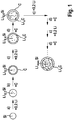
- Figure 1 shows that in the context of one embodiment of the method according to the invention, silicon particles (Si) are lithiated step by step and coated with carbon (C).
- the silicon particles (Si) are in particular in a process step a) partially lithiated.
- the silicon particles (Si) are lithiated with 0.2 lithium atoms per silicon atom. Based on the maximum stoichiometric amount of lithium Li max that can be absorbed by the silicon, for example 3.75 or 4.4 lithium atoms per silicon atom (Li 3.75 Si, Li 44 Si), the silicon particles (Si) in process step a) thus become about 5% partially lithiated.
- Figure 1 illustrates that partially lithiated silicon particles (Li 0.2 Si) are formed in the process.
- Figure 1 illustrates that in a method step b) the partially lithiated silicon particles (Li 0.2 Si) are then coated with carbon (C).
- Figure 1 illustrates that partially lithiated, carbon-coated silicon particles (Li 0.2 Si, C) are formed in the process.
- Figure 1 shows that in a method step c) the partially lithiated, carbon-coated silicon particles (Li 0.2 Si, C) are then further partially lithiated.
- the silicon particles are again with 0.2 lithium atoms per silicon atom or - based on the maximum stoichiometric amount of lithium Li max that can be absorbed by the silicon, for example 3.75 or 4.4 lithium atoms per silicon atom (Li 3.75 Si, Li 4, 4 Si) - again partially lithiated to about 5%.
- the carbon of the carbon coating can also be lithiated (Li x C).
- Figure 1 illustrates that partially lithiated, carbon-coated silicon particles (Li 0.4 Si, Li x C) are further formed.
- Figure 1 illustrates that then in a method step d) the further partially lithiated, carbon-coated silicon particles (Li 0.4 Si, Li x C) are coated again with carbon (C).
- Figure 1 illustrates that again carbon-coated, further partially lithiated silicon particles (Li 0.4 Si, Li x C, C) are formed.
- Figure 1 indicates that method steps c) and d) can be repeated several times, for example twenty times, alternately.
- Figure 1 shows that process steps c) and d) can be repeated alternately, in particular until complete lithiation of the silicon particles (Li max Si, Li x C) is achieved.
- Figure 2 shows that within the scope of another embodiment of the method silicon particles (Si) are completely lithiated (max Li) in one step, with completely lithiated silicon (Li max Si), for example Li 3.75 Si or Li 4.4 Si, being formed becomes.
- the fully lithiated silicon particles (Li max Si) are then coated with carbon (C), with a carbon coating (C) being formed.
- an embodiment based on a single coating with carbon in one step is not part of the invention.
- FIG. 10 shows an embodiment of a chemical vapor deposition apparatus 100 for producing an anode active material for a lithium cell.
- Figure 1 shows that the device 100 has a reaction space 110, for example a CVD tube, for performing chemical vapor deposition.
- Figure 3 further shows that the device 100 has a lithium precursor inlet 120 for admitting a lithium precursor into the reaction space 110 and a carbon precursor inlet 130 for admitting a carbon precursor into the reaction space 110.
- the lithium precursor inlet 120 is equipped with a lithium precursor inlet shut-off device (not shown) for the openable shut-off of the lithium precursor inlet 120.
- the carbon precursor inlet 130 is equipped with a carbon precursor inlet shut-off device (not shown) for the openable blocking of the carbon precursor inlet 130.
- the lithium precursor inlet 120 and the carbon precursor inlet 130 can advantageously be controlled by the lithium precursor inlet shut-off element and the carbon precursor inlet shut-off element, so that the lithiation and coating advantageously take place in a device 100, for example can be carried out both step by step and in one step.
- the lithium precursor inlet shut-off device and the carbon precursor inlet shut-off device can in particular be opened alternately.
- the lithium precursor inlet shut-off device in a lithiation position, can be opened and the carbon precursor inlet shut-off device closed, and in a coating position the lithium precursor inlet shut-off device can be closed and the carbon precursor inlet shut-off device open.
Landscapes
- Chemical & Material Sciences (AREA)
- General Chemical & Material Sciences (AREA)
- Chemical Kinetics & Catalysis (AREA)
- Engineering & Computer Science (AREA)
- Electrochemistry (AREA)
- Materials Engineering (AREA)
- Mechanical Engineering (AREA)
- Metallurgy (AREA)
- Organic Chemistry (AREA)
- Inorganic Chemistry (AREA)
- Composite Materials (AREA)
- Manufacturing & Machinery (AREA)
- Battery Electrode And Active Subsutance (AREA)
Description
- Die vorliegende Erfindung betrifft ein Verfahren zur Herstellung eines Anodenaktivmaterials für eine Lithium-Zelle, ein Anodenaktivmaterial, und eine Lithium-Zelle
- Silicium ist eines der vielversprechendsten Anodenmaterialien für die nächste Generation von Lithium-Ionen-Batterien, da Silicium eine sehr hohe Kapazität bietet, welche beispielsweise bei 3670 mA/g bei etwa 0,4 V gegen Lithium liegen und etwa um das Zehnfache höher als die Kapazität von Graphit sein kann.
- Herkömmliche Anoden auf der Basis von Nanosilicium weisen jedoch in der Regel kein gutes Zyklisierungsverhalten auf, da beim Zyklisieren das Silicium extreme Volumenänderungen durchläuft. Beispielsweise kann das Silicium beim Lithiieren eine Volumenexpansion um bis zu etwa 300 % vollziehen.
- Herkömmlicherweise wird während des ersten Zyklus einer Zelle beziehungsweise während der ersten Lithiierung eines Anodenaktivmaterials eine Festkörper-Elektrolyt-Grenzschicht, eine so genannte SEI-Schicht (SEI; Englisch: Solide Electrolyte Interface), aus Elektrolytzersetzungsprodukten auf der Oberfläche des Anodenmaterials ausgebildet.
- Im Fall von Silicium als Anodenaktivmaterial kann eine SEI-Schicht aus Elektrolytzersetzungsprodukten gebildet werden. Die SEI-Schicht ist im Fall von Silicium jedoch instabil und bricht mit voranschreitender Volumenexpansion ständig auf und exponiert dem Elektrolyten neue Reaktionsoberfläche, was zu einer ständigen SEI-Bildung und schließlich zur Ausbildung einer inhomogenen Schicht mit vielen Rissen und anderen Defekten, welche die Schicht während der folgenden Zyklen anfällig gegenüber Brüchen machen, führen kann.
- Die Druckschrift
US 2010/0173198 A1 betrifft eine sekundäre Lithium-Ionen-Batterie mit einer vorlithiierten Anode. - Die Druckschrift
US 2007/0099084 A1 betrifft eine hochkapazitive Elektrode und Herstellungsverfahren hierfür. - Die Druckschrift
US 2012/0100438 A1 betrifft Komposite, welche ein hochkapazitives, poröses, durch eine Schale begrenztes Aktivmaterial enthalten. - Gegenstand der Erfindung ist ein Verfahren zur Herstellung eines Anodenaktivmaterials für eine Lithium-Zelle.
- Unter einer Lithium-Zelle kann insbesondere eine elektrochemische Zelle, beispielsweise eine Batteriezelle, zum Beispiel eine sekundäre oder primäre Batteriezelle, verstanden werden, an deren elektrochemischer Reaktion Lithium beteiligt sind. Zum Beispiel kann eine Lithium-Zelle eine Lithium-Ionen-Zelle oder eine Lithium-Schwefel-Zelle oder eine Lithium Sauerstoff-Zelle, beispielsweise eine Lithium-Luft-Zelle, sein.
- In dem Verfahren wird ein Anodenaktivmaterial lithiiert und mit Kohlenstoff beschichtet. Zum Beispiel kann in dem Verfahren ein Anodenaktivmaterial (zunächst) lithiiert und das lithiierte Anodenaktivmaterial (dann) mit Kohlenstoff beschichtet werden.
- Im Rahmen einer Ausführungsform umfasst das Anodenaktivmaterial Silicium. Beispielsweise kann das Anodenmaterial aus Silicium ausgebildet sein.
- Das Anodenaktivmaterial kann beispielsweise in Form von Anodenaktivmaterialpartikel ausgebildet sein. Dabei können die Anodenaktivmaterialpartikel Silicium umfassen oder daraus ausgebildet sein. Zum Beispiel kann das Anodenaktivmaterialpartikel in Form von Siliciumpartikel ausgebildet sein. Insbesondere können dabei, beispielsweise lithiierte, Anodenaktivmaterialpartikel, zum Beispiel Siliciumpartikel, mit Kohlenstoff beschichtet werden.
- Durch das Lithiieren, welches insbesondere mit einer Lithiumlegierungsbildung einhergehen kann, expandiert das Anodenaktivmaterial, beispielsweise die Anodenaktivmaterialpartikel, zum Beispiel die Siliciumpartikel, so dass das lithiierte (und damit expandierte) Anodenaktivmaterial, beispielsweise die Anodenaktivmaterialpartikeln, zum Beispiel die Siliciumpartikel, mit dem Kohlenstoff beschichtet werden.
- Das Verfahren ermöglicht vorteilhafterweise lithiiertes (und damit expandiertes) Anodenaktivmaterial, beispielsweise lithiierte (und damit expandierte) Anodenaktivmaterialpartikel, zum Beispiel Siliciumpartikel, mit einer stabilisierten Oberflächenschicht zu synthetisieren. Vorteilhafterweise kann so eine Anodenaktivmaterial bereitgestellt werden, welches insbesondere bis hin zu seinem maximalen Volumen, beispielsweise bis hin zu einem etwa Vierfachen seines Volumens, zum Beispiel auf ein 3,75-faches oder mehr seines Volumens, im Fall von vollständig lithiiertem Silicium (LimaxSi, beispielsweise mit (≥) 3,75 Li/Si, zum Beispiel Li3,75Si oder Li4,4Si), expandiert sein kann und eine Kohlenstoffoberflächenbeschichtung aufweist. Insbesondere können so vorteilhafterweise Anodenaktivmaterialpartikel, zum Beispiel Siliciumpartikel, bereitgestellt werden, welche insbesondere bis hin zu ihrem maximalen Volumen, beispielsweise bis zu einem etwa Vierfachen ihres Volumens, zum Beispiel auf ein 3,75-faches oder mehr ihres Volumens, im Fall vollständig lithiiertem Silicium (LimaxSi), expandiert sein können und eine Kohlenstoffoberflächenbeschichtung aufweisen. Dabei kann die Kohlenstoffoberflächenbeschichtung vorteilhafterweise als Schutzschicht und Elektrolyt-Barriere dienen sowie zudem elektrische Leitfähigkeit verleihen.
- Durch das Beschichten mit Kohlenstoff kann vorteilhafterweise eine Schicht auf dem Anodenaktivmaterial, beispielsweise auf den Anodenaktivmaterialpartikeln, zum Beispiel Siliciumpartikeln, realisiert werden, welche eine gewisse mechanische Stabilität aufweisen und beispielsweise sowohl beim lithiumlegierungsbildungsbedingten Expandieren als auch beim lithiumlegierungsrückbildungsbedingten Schrumpfen des Anodenaktivmaterials, beispielsweise der Anodenaktivmaterialpartikel, zum Beispiel Siliciumpartikel, mechanisch stabil bleiben kann, insbesondere ohne - im Gegensatz zu einer auf unbehandeltem Silicium, beispielsweise herkömmlichen Siliciumpartikeln, ausgebildeten SEI-Schicht - beim Expandieren zu brechen und/oder ohne - insbesondere auch im Gegensatz zu einer auf vorlithiiertem Silicium, zum Beispiel vorlithiierten Siliciumpartikeln, ausgebildeten SEI-Schicht - beim Schrumpfen zu kollabieren.
- Somit kann durch das Verfahren vorteilhafterweise kohlenstoffbeschichtetes und dadurch mechanisch stabilisiertes, vorlithiiertes Anodenaktivmaterial, beispielsweise Silicium, bereitgestellt werden.
- Auf der Kohlenstoffbeschichtung kann vorteilhafterweise bereits während des ersten Zyklisierungszyklus - zum Beispiel wenn die Zellspannung einer, beispielsweise carbonathaltigen, Zelle unter 0,8 V sinkt - eine SEI-Schicht gebildet werden, welche vorteilhafterweise in den folgenden Zyklen stabil bleiben kann. Dabei kann die SEI-Schicht auf der Kohlenstoffbeschichtung insbesondere stabil bleiben, da der Kohlenstoff beim Lithiieren lediglich eine minimale oder sogar keine - beispielsweise im Fall einer vollständig lithiierten Kohlenstoffbeschichtung - Volumenexpansion vollzieht.
- So kann wiederum vorteilhafterweise das Zyklisierungsverhalten einer damit ausgestatten Lithium-Zelle verbessert werden.
- Im Rahmen einer weiteren Ausführungsform wird das Anodenaktivmaterial mittels chemischer Gasphasenabscheidung lithiiert. Durch chemische Gasphasenabscheidung kann vorteilhafterweise eine homogene Lithiierung des Anodenaktivmaterials erzielt werden. In Kombination mit einem im Folgenden erläuterten Beschichten mit Kohlenstoff mittels chemischer Gasphasenabscheidung kann so zudem die Prozessführung vereinfacht werden.
- Bei dem Lithiieren des Anodenaktivmaterials mittels chemischer Gasphasenabscheidung kann insbesondere ein Lithium-Präkursor verwendet werden.
- Im Rahmen einer Ausgestaltung dieser Ausführungsform umfasst oder ist der Lithium-Präkursor mindestens einen lithiierten Kohlenwasserstoff, beispielsweise mindestens ein lithiiertes Alkin, zum Beispiel lithiiertes Acetylen, und/oder mindestens einen lithiierten aromatischen Kohlenwasserstoff, zum Beispiel lithiiertes Toluol.
- Im Rahmen einer weiteren Ausführungsform wird das, beispielsweise lithiierte, Anodenaktivmaterial mittels chemischer Gasphasenabscheidung mit Kohlenstoff beschichtet. Eine mittels chemischer Gasphasenabscheidung ausgebildete Kohlenstoffbeschichtung kann vorteilhafterweise eine besonders hohe Homogenität und/oder mechanische Stabilität aufweisen und sowohl beim lithiumlegierungsbildungsbedingten Expandieren als auch beim lithiumlegierungsrückbildungsbedingten Schrumpfen des Anodenaktivmaterials, insbesondere der Anodenaktivmaterialpartikel, mechanisch stabil bleiben. Durch chemische Gasphasenabscheidung kann zudem vorteilhafterweise die Dicke und/oder Morphologie der Beschichtung, beispielsweise in Form eines Films, gezielt eingestellt werden und eine große Auswahl an Kohlenstoff-Präkursoren eingesetzt werden, welche beispielsweise im Hinblick auf ein Einstellen einer gewünschten Morphologie und/oder Leitfähigkeit der Beschichtung ausgewählt werden können.
- Bei dem Beschichten des lithiierten Anodenaktivmaterials mittels chemischer Gasphasenabscheidung kann insbesondere ein Kohlenstoff-Präkursor verwendet werden.
- Im Rahmen einer Ausgestaltung dieser Ausführungsform umfasst oder ist der Kohlenstoff-Präkursor mindestens einen Kohlenwasserstoff, beispielsweise mindestens ein Alkin, zum Beispiel Acetylen, und/oder mindestens einen aromatischen Kohlenwasserstoff, zum Beispiel Toluol.
- Das Lithiieren und Beschichten mit Kohlenstoff erfolgt erfindungsgemäß schrittweise, durch alternierend wiederholtes beispielsweise teilweises Lithiieren des Anodenaktivmaterials und Beschichten des teilweise lithiierten Anodenaktivmaterials mit Kohlenstoff, beispielsweise bis zum Erreichen einer vollständigen Lithiierung (und damit einer maximalen Expansion).
- Im Rahmen der Erfindung welche auf einem schrittweisen Lithiieren und Beschichten mit Kohlenstoff basiert - wird das Lithiieren und Beschichten mit Kohlenstoff alternierend wiederholt. Durch alternierendes Lithiieren und Beschichten mit Kohlenstoff kann vorteilhafterweise die Kohlenstoffbeschichtung zum einen lithiiert und zum anderen durch die beim Lithiieren auftretende Volumenexpansion verdichtet werden, wodurch wiederum vorteilhafterweise die Stabilität der Kohlenstoffbeschichtung erhöht werden kann.
- Im Rahmen einer weiteren, alternativen oder zusätzlichen Ausführungsform - welche auf einem schrittweisen Lithiieren und Beschichten mit Kohlenstoff basiert - wird in dem Verfahren das Anodenaktivmaterial teilweise lithiiert. Dabei kann insbesondere das teilweise lithiierthe Anodenaktivmaterial mit Kohlenstoff beschichtet werden. Zum Beispiel kann in dem Verfahren das Anodenaktivmaterial (zunächst) teilweise lithiiert und (dann) das teilweise lithiierthe Anodenaktivmaterial mit Kohlenstoff beschichtet werden.
- Im Rahmen einer Ausgestaltung dieser Ausführungsform wird das teilweise lithiierte, kohlenstoffbeschichtete Anodenmaterial (dann) weiter teilweise lithiiert. Durch wiederholtes teilweises Lithiieren kann vorteilhafterweise die Kohlenstoffbeschichtung lithiiert und durch den lithiierungsbedingten Expansionsschritt verdichtet und auf diese Weise deren Stabilität erhöht werden.
- Im Rahmen einer weiteren Ausgestaltung dieser Ausführungsform wird das weiter teilweise lithiierte, kohlenstoffbeschichtete Anodenaktivmaterial (dann) erneut mit Kohlenstoff beschichtet. Durch wiederholtes Kohlenstoffbeschichten kann vorteilhafterweise die Beschichtung weiter stabilisiert werden.
- Beispielsweise können dabei Anodenaktivmaterialpartikel, zum Beispiel Siliciumpartikel, (zunächst) teilweise lithiiert und (dann) die teilweise lithiierten Anodenaktivmaterialpartikel, zum Beispiel Siliciumpartikel, mit Kohlenstoff beschichtet werden. Die teilweise lithiierten, kohlenstoffbeschichteten Anodenmaterialpartikel, zum Beispiel Siliciumpartikel, können (dann) beispielsweise weiter teilweise lithiiert werden. Die weiter teilweise lithiierten, kohlenstoffbeschichteten Anodenaktivmaterialpartikel, zum Beispiel Siliciumpartikel, können (dann) beispielsweise erneut mit Kohlenstoff beschichtet werden.
- Im Rahmen einer weiteren Ausführungsform wird das teilweise Lithiieren und Beschichten mit Kohlenstoff alternierend wiederholt.
- Im Rahmen der Erfindung wird das, insbesondere teilweise, Lithiieren und Beschichten mit Kohlenstoff mindestens zweifach, insbesondere mindestens zehnfach, beispielsweise mindestens zwanzigfach, alternierend wiederholt. So kann vorteilhafterweise eine besonders stabile Kohlenstoffoberflächenbeschichtung erzielt werden.
- Im Rahmen einer weiteren Ausführungsform wird das, insbesondere teilweise, Lithiieren und Beschichten mit Kohlenstoff bis zum Erreichen einer durchschnittlichen Schichtdicke der Kohlenstoffbeschichtung in einem Bereich von ≥ 50 nm bis ≤ 0,5 µm alternierend wiederholt. So kann vorteilhafterweise eine besonders stabile Kohlenstoffoberflächenbeschichtung erzielt werden.
- Im Rahmen einer weiteren Ausführungsform wird das, insbesondere teilweise, Lithiieren und Beschichten mit Kohlenstoff bis zum Erreichen einer vollständigen Lithiierung des Anodenaktivmaterials alternierend wiederholt. So kann vorteilhafterweise eine besonders stabile Kohlenstoffoberflächenbeschichtung erzielt werden, insbesondere welche selbst im expandiertesten Zustand des Anodenaktivmaterials, beispielsweise der Anodenaktivmaterialpartikel, zum Beispiel Siliciumpartikel, stabil ist.
- Zum Beispiel kann das Anodenaktivmaterial bis zum Erreichen einer vollständigen Lithiierung alternierend wiederholt teilweises lithiiert und das teilweise lithiierte Anodenaktivmaterial mit Kohlenstoff beschichtet werden. Beispielsweise können dabei die Anodenaktivmaterialpartikel, zum Beispiel Siliciumpartikel, bis zum Erreichen einer vollständigen Lithiierung alternierend wiederholt teilweises lithiiert und die teilweise lithiierten Anodenaktivmaterialpartikel, zum Beispiel Siliciumpartikel, mit Kohlenstoff beschichtet werden.
- Im Rahmen einer weiteren Ausführungsform wird das Anodenaktivmaterial, bezogen auf die durch das Anodenaktivmaterial maximal aufnehmbare stöchiometrische Lithiummenge, (jeweils - insbesondere bei jedem teilweisen Lithiieren) zu ≤ 20 % teilweise lithiiert. Insbesondere kann das Anodenaktivmaterial, bezogen auf die durch das Anodenaktivmaterial maximal aufnehmbare stöchiometrische Lithiummenge, (jeweils - insbesondere bei jedem teilweisen Lithiieren) zu ≤ 10 %, beispielsweise jeweils zu ≤ 5 %, teilweise lithiiert werden. Beispielsweise können dabei die Anodenaktivmaterialpartikel, zum Beispiel Siliciumpartikel, bezogen auf die durch die Anodenaktivmaterialpartikel beziehungsweise Siliciumpartikel maximal aufnehmbare stöchiometrische Lithiummenge, (jeweils - insbesondere bei jedem teilweisen Lithiieren) zu ≤ 20 %, insbesondere jeweils zu ≤ 10 %, beispielsweise jeweils zu ≤ 5 %, teilweise lithiiert werden.
- Zum Beispiel kann das Verfahren die Verfahrensschritte:
- a) teilweises Lithiieren von Anodenaktivmaterial und
- b) Beschichten des teilweise lithiierten Anodenaktivmaterials mit Kohlenstoff, umfassen. Beispielsweise können dabei in Verfahrensschritt a) Anodenaktivmaterialpartikel, zum Beispiel Siliciumpartikel, teilweise lithiiert werden und in Verfahrensschritt b) die lithiierten Anodenaktivmaterialpartikel, zum Beispiel Siliciumpartikel, mit Kohlenstoff beschichtet werden.
- Dabei umfasst das Verfahren weiterhin den Verfahrensschritt:
c) weiteres teilweises Lithiieren des teilweise lithiierten, kohlenstoffbeschichteten Anodenaktivmaterials. Dabei werden in Verfahrensschritt c) teilweise lithiierte, kohlenstoffbeschichtete Anodenaktivmaterialpartikel, zum Beispiel Siliciumpartikel, weiter teilweise. - Weiterhin umfasst das Verfahren dabei den Verfahrensschritt:
d) erneutes Beschichten des weiter teilweise lithiierten, kohlenstoffbeschichteten Anodenaktivmaterials mit Kohlenstoff. Dabei werden in Verfahrensschritt d) weiter teilweise lithiierte, kohlenstoffbeschichtete Anodenaktivmaterialpartikel, zum Beispiel Siliciumpartikel, mit Kohlenstoff erneut beschichtet. Insbesondere kann das Anodenaktivmaterial in Verfahrensschritt a) beziehungsweise in den Verfahrensschritten a) und c) jeweils zu ≤ 20 %, insbesondere jeweils zu ≤ 10 %, beispielsweise jeweils zu ≤ 5 %, bezogen auf die durch das Anodenaktivmaterial maximal aufnehmbare stöchiometrische Lithiummenge, teilweise lithiiert werden. Beispielsweise können die Anodenaktivmaterialpartikel, zum Beispiel Siliciumpartikel, jeweils zu ≤ 20 %, insbesondere jeweils zu ≤ 10 %, beispielsweise mit ≤ 5 %, bezogen auf die durch die Anodenaktivmaterialpartikel, zum Beispiel Siliciumpartikel, maximal aufnehmbare stöchiometrische Lithiummenge, teilweise lithiiert werden. - Dabei werden die Verfahrensschritte c) und d) mindestens zweifach, beispielsweise mindestens zehnfach, zum Beispiel mindestens zwanzigfach, alternierend wiederholt werden. Zum Beispiel können die Verfahrensschritte c) und d) bis zum Erreichen einer vollständigen Lithiierung alternierend wiederholt werden.
- Im Rahmen einer anderen Ausführungsform wird das Anodenaktivmaterial, beispielsweise Silicium, insbesondere bis zum Erreichen einer vollständigen Lithiierung, vollständig lithiiert und dann mit Kohlenstoff beschichtet. Insbesondere können dabei die Anodenaktivmaterialpartikel, zum Beispiel Siliciumpartikel, insbesondere bis zum Erreichen einer vollständigen Lithiierung, vollständig lithiiert und dann mit Kohlenstoff beschichtet werden. So kann vorteilhafterweise eine Kohlenstoffoberflächenbeschichtung erzielt werden, welche selbst im expandiertesten Zustand der Anodenaktivmaterialpartikel, insbesondere Siliciumpartikel, stabil ist.
- Im Rahmen einer weiteren Ausführungsform wird das Verfahren durch eine im Folgenden erläuterte Vorrichtung durchgeführt.
- Hinsichtlich weiterer technischer Merkmale und Vorteile des erfindungsgemäßen Verfahrens wird hiermit explizit auf die Erläuterungen im Zusammenhang mit der Vorrichtung, dem erfindungsgemäßen Anodenaktivmaterial und der erfindungsgemäßen Lithium-Zelle sowie auf die Figuren und die Figurenbeschreibung verwiesen.
- Ein weiterer Gegenstand ist eine chemische Gasphasenabscheidungsvorrichtung zur Herstellung eines Anodenaktivmaterials für eine Lithium-Zelle.
- Die Vorrichtung kann insbesondere einen Reaktionsraum, beispielsweise in Form einer Röhre, zur Durchführung von chemischer Gasphasenabscheidung, einen Lithium-Präkursor-Einlass zum Einlassen eines Lithium-Präkursors in den Reaktionsraum und ein Lithium-Präkursor-Einlass-Absperrorgan zum öffenbaren Absperren des Lithium-Präkursor-Einlasses sowie einen Kohlenstoff-Präkursor-Einlass zum Einlassen eines Kohlenstoff-Präkursors in den Reaktionsraum und ein Kohlenstoff-Präkursor-Einlass-Absperrorgan zum öffenbaren Absperren des Kohlenstoff-Präkursor-Einlasses umfassen.
- Durch das Lithium-Präkursor-Einlass-Absperrorgan und das Kohlenstoff-Präkursor-Einlass-Absperrorgan können vorteilhafterweise die beiden Einlässe für den Lithium- und Kohlenstoff-Präkursor, insbesondere der Lithium-Präkursor-Einlass und der Kohlenstoff-Präkursor-Einlass, kontrolliert werden. So kann das Lithiieren und Beschichten vorteilhafterweise schrittweise oder in einem Schritt durchgeführt werden.
- Das Lithium-Präkursor-Einlass-Absperrorgan und das Kohlenstoff-Präkursor-Einlass-Absperrorgan können beispielsweise Ventile sein. Insbesondere können das Lithium-Präkursor-Einlass-Absperrorgan und das Kohlenstoff-Präkursor-Einlass-Absperrorgan automatisch steuerbar sein. Beispielsweise können das Lithium-Präkursor-Einlass-Absperrorgan und das Kohlenstoff-Präkursor-Einlass-Absperrorgan alternierend öffenbar sein.
- Im Rahmen einer Ausführungsform ist in einer Lithiierungsstellung das Lithium-Präkursor-Einlass-Absperrorgan geöffnet und das Kohlenstoff-Präkursor-Einlass-Absperrorgan geschlossen und/oder in einer Beschichtungsstellung das Lithium-Präkursor-Einlass-Absperrorgan geschlossen und das Kohlenstoff-Präkursor-Einlass-Absperrorgan geöffnet.
- In dem Reaktionsraum kann beispielsweise eine Anodenaktivmaterialaufnahme zur Aufnahme von, zum Beispiel pulverförmigem, Anodenaktivmaterial vorgesehen sein. Die Anodenaktivmaterialaufnahme kann beispielsweise ein, insbesondere offener, Behälter sein.
- Die Vorrichtung kann beispielsweise zur Herstellung eines Anodenaktivmaterials für eine Lithium-Ionen-Zelle oder eine Lithium-Schwefel-Zelle oder eine Lithium Sauerstoff-Zelle, beispielsweise eine Lithium-Luft-Zelle, ausgelegt sein.
- Die Vorrichtung kann insbesondere zur Durchführung eines erfindungsgemäßen Verfahrens ausgelegt sein beziehungsweise dieses durchführen.
- Hinsichtlich weiterer technischer Merkmale und Vorteile der Vorrichtung wird hiermit explizit auf die Erläuterungen im Zusammenhang mit dem erfindungsgemäßen Verfahren, dem erfindungsgemäßen Anodenaktivmaterial und der erfindungsgemäßen Lithium-Zelle sowie auf die Figuren und die Figurenbeschreibung verwiesen.
- Ein weiterer Gegenstand ist ein Anodenaktivmaterial für eine Lithium-Zelle. Das Anodenaktivmaterial kann beispielsweise ein Anodenaktivmaterial für eine Lithium-Ionen-Zelle oder eine Lithium-Schwefel-Zelle oder eine Lithium Sauerstoff-Zelle, beispielsweise eine Lithium-Luft-Zelle, sein.
- Im Rahmen der Erfindung ist das Anodenaktivmaterial durch ein erfindungsgemäßes Verfahren hergestellt.
- Im Rahmen einer weiteren Ausführungsform umfasst das Anodenaktivmaterial Anodenaktivmaterialpartikel, beispielsweise Siliciumpartikel, welche mit mindestens zwei lithiierten Kohlenstoffbeschichtungen, beispielsweise mit mindestens zehn lithiierten Kohlenstoffbeschichtungen, zum Beispiel mit mindestens zwanzig lithiierten Kohlenstoffbeschichtungen, beschichtet sein. Ein derartiges Anodenaktivmaterial kann vorteilhafterweise durch schrittweises Lithiieren und Beschichten mit Kohlenstoff hergestellt werden.
- Mittels eines erfindungsgemäßen Verfahrens und/oder mittels einer erfindungsgemäßen Vorrichtung hergestelltes Anodenaktivmaterial kann beispielsweise mittels Transmissionselektronenmikroskopie (TEM) und/oder Elektronenenergieverlustspektroskopie (EELS; Englisch: Electron Energy Loss Spectroscopy) und/oder Rasterelektronenmikroskopie (SEM; Englisch: Scanning Electron Microscope) und/oder Raman-Spektroskopie, Röntgenphotoelektronenspektroskopie (XPS, Englisch: X-ray Photoelectron Spectroscopy), beispielsweise mit Tiefenprofilierung, nachgewiesen werden.
- Hinsichtlich weiterer technischer Merkmale und Vorteile des erfindungsgemäßen Anodenaktivmaterials wird hiermit explizit auf die Erläuterungen im Zusammenhang mit dem erfindungsgemäßen Verfahren, der Vorrichtung und der erfindungsgemäßen Lithium-Zelle sowie auf die Figuren und die Figurenbeschreibung verwiesen.
- Ferner betrifft die Erfindung eine Lithium-Zelle welche ein erfindungsgemäßes Anodenmaterial umfasst. Die Lithium-Zelle kann zum Beispiel eine Lithium-Ionen-Zelle oder eine Lithium-Schwefel-Zelle oder eine Lithium Sauerstoff-Zelle, beispielsweise eine Lithium-Luft-Zelle, sein.
- Hinsichtlich weiterer technischer Merkmale und Vorteile der erfindungsgemäßen Zelle wird hiermit explizit auf die Erläuterungen im Zusammenhang mit dem erfindungsgemäßen Verfahren, der Vorrichtung und dem erfindungsgemäßen Anodenaktivmaterial sowie auf die Figuren und die Figurenbeschreibung verwiesen.
- Weitere Vorteile und vorteilhafte Ausgestaltungen der erfindungsgemäßen Gegenstände werden durch die Zeichnungen veranschaulicht und in der nachfolgenden Beschreibung erläutert. Dabei ist zu beachten, dass die Zeichnungen nur beschreibenden Charakter haben und nicht dazu gedacht sind, die Erfindung in irgendeiner Form einzuschränken. Es zeigen
- Fig. 1
- ein Schema zur Veranschaulichung einer Ausführungsform des erfindungsgemäßen Verfahrens, im Rahmen derer Siliciumpartikel schrittweise und alternierend wiederholt teilweise lithiiert und mit Kohlenstoff beschichtet werden;
- Fig. 2
- ein Schema zur Veranschaulichung einer anderen Ausführungsform des erfindungsgemäßen Verfahrens, im Rahmen derer Siliciumpartikel in einem Schritt vollständig lithiiert werden und dann mit Kohlenstoff beschichtet werden; und
- Fig. 3
- einen schematischen Querschnitt durch eine Ausführungsform einer chemischen Gasphasenabscheidungsvorrichtung.
-
Figur 1 zeigt, dass im Rahmen einer Ausführungsform des erfindungsgemäßen Verfahrens Siliciumpartikel (Si) schrittweise lithiiert und mit Kohlenstoff (C) beschichtet werden. Die Siliciumpartikel (Si) werden dabei insbesondere in einem Verfahrensschritt a) teilweises lithiiert. Dabei werden die Siliciumpartikel (Si) pro Siliciumatom mit 0,2 Lithiumatomen lithiiert. Bezogen auf die durch das Silicium maximal aufnehmbare stöchiometrische Lithiummenge Limax, zum Beispiel von 3,75 beziehungsweise 4,4 Lithiumatomen pro Siliciumatom (Li3,75Si, Li44Si), werden die Siliciumpartikel (Si) in Verfahrensschritt a) somit zu etwa 5 % teilweise lithiiert.Figur 1 veranschaulicht, dass dabei teilweise lithiierte Siliciumpartikel (Li0,2Si) ausgebildet werden. -
Figur 1 illustriert, dass in einem Verfahrensschritt b) dann die teilweise lithiierten Siliciumpartikel (Li0,2Si) mit Kohlenstoff (C) beschichtet werden.Figur 1 veranschaulicht, dass dabei teilweise lithiierte, kohlenstoffbeschichtete Siliciumpartikel (Li0,2Si,C) ausgebildet werden. -
Figur 1 zeigt, dass in einem Verfahrensschritt c) die teilweise lithiierten, kohlenstoffbeschichteten Siliciumpartikel (Li0,2Si,C) dann weiter teilweise lithiiert werden. Dabei werden die Siliciumpartikel wieder pro Siliciumatom mit 0,2 Lithiumatomen beziehungsweise - bezogen auf die durch das Silicium maximal aufnehmbare stöchiometrische Lithiummenge Limax, zum Beispiel von 3,75 beziehungsweise 4,4 Lithiumatomen pro Siliciumatom (Li3,75Si, Li4,4Si) - wieder zu etwa 5 % teilweise lithiiert. Dabei kann auch der Kohlenstoff der Kohlenstoffbeschichtung lithiiert (LixC) werden.Figur 1 veranschaulicht, dass dabei weiter teilweise lithiierte, kohlenstoffbeschichtete Siliciumpartikel (Li0,4Si,LixC) ausgebildet werden. -
Figur 1 veranschaulicht, dass dann in einem Verfahrensschritt d) die weiter teilweise lithiierten, kohlenstoffbeschichteten Siliciumpartikel (Li0,4Si,LixC) erneut mit Kohlenstoff (C) beschichtet werden.Figur 1 veranschaulicht, dass dabei erneut kohlenstoffbeschichtete, weiter teilweise lithiierte Siliciumpartikel (Li0,4Si,LixC,C) ausgebildet werden. -
Figur 1 deutet an, dass die Verfahrensschritte c) und d) mehrfach, beispielsweise zwanzigfach, alternierend wiederholt werden können. -
Figur 1 zeigt, dass dabei die Verfahrensschritte c) und d) insbesondere bis zum Erreichen einer vollständigen Lithiierung der Siliciumpartikel (LimaxSi,LixC) alternierend wiederholt werden können. -
Figur 2 zeigt, dass im Rahmen einer anderen Ausführungsform des Verfahrens Siliciumpartikel (Si) in einem Schritt vollständig lithiiert (max Li) werden, wobei vollständig lithiiertes Silicium (LimaxSi), zum Beispiel Li3,75Si beziehungsweise Li4,4Si, ausgebildet wird. Die vollständig lithiierten Siliciumpartikel (LimaxSi) werden dann mit Kohlenstoff (C) beschichtet, wobei eine Kohlenstoffbeschichtung (C) ausgebildet wird. Allerdings ist eine Ausführungsform, welche auf einem einmaligen Beschichten mit Kohlenstoff in einem Schritt basiert, nicht Teil der Erfindung. -
Figur 3 zeigt eine Ausführungsform einer chemischen Gasphasenabscheidungsvorrichtung 100 zur Herstellung eines Anodenaktivmaterials für eine Lithium-Zelle.Figur 1 zeigt, dass dabei die Vorrichtung 100 einen Reaktionsraum 110, beispielsweise eine CVD-Röhre, zur Durchführung von chemischer Gasphasenabscheidung aufweist. In dem Reaktionsraum 100 ist dabei eine Anodenaktivmaterialaufnahme 140 zur Aufnahme von Anodenaktivmaterial, zum Beispiel Silicium (Si), vorgesehen. -
Figur 3 zeigt weiterhin, dass die Vorrichtung 100 einen Lithium-Präkursor-Einlass 120 zum Einlassen eines Lithium-Präkursors in den Reaktionsraum 110 und einen Kohlenstoff-Präkursor-Einlass 130 zum Einlassen eines Kohlenstoff-Präkursors in den Reaktionsraum 110 aufweist. Der Lithium-Präkursor-Einlass 120 ist dabei mit einem Lithium-Präkursor-Einlass-Absperrorgan (nicht dargestellt) zum öffenbaren Absperren des Lithium-Präkursor-Einlasses 120 ausgestattet. Der Kohlenstoff-Präkursor-Einlass 130 ist dabei mit einem Kohlenstoff-Präkursor-Einlass-Absperrorgan (nicht dargestellt) zum öffenbaren Absperren des Kohlenstoff-Präkursor-Einlasses 130 ausgestattet. - Durch das Lithium-Präkursor-Einlass-Absperrorgan und das Kohlenstoff-Präkursor-Einlass-Absperrorgan können vorteilhafterweise der Lithium-Präkursor-Einlass 120 und der Kohlenstoff-Präkursor-Einlass 130 kontrolliert werden, so dass das Lithiieren und Beschichten vorteilhafterweise in einer Vorrichtung 100 beispielsweise sowohl schrittweise als auch in einem Schritt durchgeführt werden kann.
- Dabei kann das Lithium-Präkursor-Einlass-Absperrorgan und das Kohlenstoff-Präkursor-Einlass-Absperrorgan insbesondere alternierend öffenbar sein. Dabei kann beispielsweise in einer Lithiierungsstellung das Lithium-Präkursor-Einlass-Absperrorgan geöffnet und das Kohlenstoff-Präkursor-Einlass-Absperrorgan geschlossen und einer Beschichtungsstellung das Lithium-Präkursor-Einlass-Absperrorgan geschlossen und das Kohlenstoff-Präkursor-Einlass-Absperrorgan geöffnet sein.
Claims (14)
- Verfahren zur Herstellung eines Anodenaktivmaterials für eine Lithium-Zelle, in dem ein Anodenaktivmaterial, insbesondere teilweise lithiiert und mit Kohlenstoff beschichtet wird, dadurch gekennzeichnet, dass das Lithiieren und Beschichten mit Kohlenstoff alternierend wiederholt wird.
- Verfahren nach Anspruch 1, dadurch gekennzeichnet, dass das Anodenaktivmaterial mittels chemischer Gasphasenabscheidung lithiiert wird.
- Verfahren nach Anspruch 1 oder 2, dadurch gekennzeichnet, dass das, insbesondere teilweise, Lithiieren und Beschichten mit Kohlenstoff mindestens zehnfach wiederholt wird.
- Verfahren nach einem der Ansprüche 1 bis 3, wobei das, insbesondere teilweise, Lithiieren und Beschichten mit Kohlenstoff bis zum Erreichen einer durchschnittlichen Schichtdicke der Kohlenstoffbeschichtung in einem Bereich von ≥ 50 nm bis ≤ 0,5 µm alternierend wiederholt wird.
- Verfahren nach einem der Ansprüche 1 bis 4, wobei das Lithiieren und Beschichten mit Kohlenstoff bis zum Erreichen einer vollständigen Lithiierung des Anodenaktivmaterials alternierend wiederholt wird.
- Verfahren nach einem der Ansprüche 2 bis 5, wobei das Anodenaktivmaterial, bezogen auf die durch das Anodenaktivmaterial maximal aufnehmbare stöchiometrische Lithiummenge, jeweils zu ≤ 20 %, insbesondere jeweils zu ≤ 5 %, teilweise lithiiert wird.
- Verfahren nach einem der Ansprüche 1 bis 6, wobei bei dem Lithiieren des Anodenaktivmaterials mittels chemischer Gasphasenabscheidung ein Lithium-Präkursor verwendet wird, wobei der Lithium-Präkursor mindestens einen lithiierten Kohlenwasserstoff, insbesondere lithiiertes Acetylen und/oder lithiiertes Toluol, umfasst.
- Verfahren nach einem der Ansprüche 1 bis 7, wobei das Anodenaktivmaterial mittels chemischer Gasphasenabscheidung mit Kohlenstoff beschichtet wird.
- Verfahren nach Anspruch 8, wobei bei dem Beschichten des lithiierten Anodenaktivmaterials mittels chemischer Gasphasenabscheidung ein Kohlenstoff-Präkursor verwendet wird, wobei der Kohlenstoff-Präkursor mindestens einen Kohlenwasserstoff, insbesondere Acetylen und/oder Toluol umfasst.
- Verfahren nach einem der Ansprüche 1 bis 9, wobei das Anodenaktivmaterial Silicium umfasst oder daraus ausgebildet ist.
- Verfahren nach einem der Ansprüche 1 bis 10, dadurch gekennzeichnet, dass eine chemische Gasphasenabscheidungsvorrichtung (100) zur Herstellung des Anodenaktivmaterials für eine Lithium-Zelle verwendet wird, umfassend- einen Reaktionsraum (110) zur Durchführung von chemischer Gasphasenabscheidung,- einen Lithium-Präkursor-Einlass (120) zum Einlassen eines Lithium-Präkursors in den Reaktionsraum (110) und einem Lithium-Präkursor-Einlass-Absperrorgan zum öffenbaren Absperren des Lithium-Präkursor-Einlasses (120),- einen Kohlenstoff-Präkursor-Einlass (130) zum Einlassen eines Kohlenstoff-Präkursors in den Reaktionsraum (110) und einem Kohlenstoff-Präkursor-Einlass-Absperrorgan zum öffenbaren Absperren des Kohlenstoff-Präkursor-Einlasses (130).
- Verfahren nach Anspruch 11,
wobei in einer Lithiierungsstellung das Lithium-Präkursor-Einlass-Absperrorgan geöffnet und das Kohlenstoff-Präkursor-Einlass-Absperrorgan geschlossen ist, und/oder
wobei in einer Beschichtungsstellung das Lithium-Präkursor-Einlass-Absperrorgan geschlossen und das Kohlenstoff-Präkursor-Einlass-Absperrorgan geöffnet ist. - Anodenaktivmaterial für eine Lithium-Zelle, hergestellt durch ein Verfahren gemäß einem der vorhergehenden Ansprüche, umfassend Anodenaktivmaterialpartikel, insbesondere Siliziumpartikel, welche mit mindestens zwei lithiierten Kohlenstoffbeschichtungen beschichtet sind.
- Lithium-Zelle, umfassend ein Anodenmaterial nach Anspruch 13.
Applications Claiming Priority (2)
| Application Number | Priority Date | Filing Date | Title |
|---|---|---|---|
| DE102015217809.9A DE102015217809A1 (de) | 2015-09-17 | 2015-09-17 | Vorlithiiertes, kohlenstoffbeschichtetes Anodenaktivmaterial |
| PCT/EP2016/070822 WO2017045950A1 (de) | 2015-09-17 | 2016-09-05 | Vorlithiiertes, kohlenstoffbeschichtetes anodenaktivmaterial |
Publications (2)
| Publication Number | Publication Date |
|---|---|
| EP3350857A1 EP3350857A1 (de) | 2018-07-25 |
| EP3350857B1 true EP3350857B1 (de) | 2021-02-17 |
Family
ID=56920687
Family Applications (1)
| Application Number | Title | Priority Date | Filing Date |
|---|---|---|---|
| EP16763744.6A Active EP3350857B1 (de) | 2015-09-17 | 2016-09-05 | Vorlithiiertes, kohlenstoffbeschichtetes anodenaktivmaterial |
Country Status (5)
| Country | Link |
|---|---|
| EP (1) | EP3350857B1 (de) |
| KR (1) | KR20180051536A (de) |
| CN (1) | CN108028368B (de) |
| DE (1) | DE102015217809A1 (de) |
| WO (1) | WO2017045950A1 (de) |
Families Citing this family (10)
| Publication number | Priority date | Publication date | Assignee | Title |
|---|---|---|---|---|
| KR102530195B1 (ko) * | 2019-01-18 | 2023-05-10 | 주식회사 엘지에너지솔루션 | 이차전지용 음극의 제조방법 |
| DE112019007359A5 (de) | 2019-05-21 | 2022-03-17 | Wacker Chemie Ag | Lithium-Ionen-Batterien |
| CN110428983B (zh) * | 2019-08-22 | 2021-07-16 | 杭州求实新材料科技有限公司 | 一种钠离子电容器MXene电极材料的预钠化方法 |
| KR102747621B1 (ko) * | 2020-03-27 | 2024-12-31 | 주식회사 엘지에너지솔루션 | 음극의 제조방법 |
| KR102490930B1 (ko) * | 2020-07-27 | 2023-01-26 | 한국과학기술연구원 | 사전리튬화 용액 및 이를 이용한 사전리튬화된 음극의 제조방법 |
| WO2022085995A1 (ko) | 2020-10-19 | 2022-04-28 | 주식회사 엘지에너지솔루션 | 무기 코팅층이 형성된 음극의 제조방법 |
| EP4260386A4 (de) * | 2020-12-08 | 2025-07-09 | Applied Materials Inc | Vorlithiierung und lithiummetallfreie anodenbeschichtungen |
| KR20230035394A (ko) | 2021-06-17 | 2023-03-13 | 와커 헤미 아게 | 리튬-이온 배터리에서 실리콘-함유 애노드의 전리튬화 방법 |
| CN114843491A (zh) * | 2022-05-13 | 2022-08-02 | 齐鲁中科光物理与工程技术研究院 | 一种高容量、高循环稳定性负极材料及其制备方法 |
| CN115621416A (zh) * | 2022-06-22 | 2023-01-17 | 西北工业大学 | 一种具有空气稳定的负极预锂化界面层的负极及制备方法 |
Family Cites Families (7)
| Publication number | Priority date | Publication date | Assignee | Title |
|---|---|---|---|---|
| WO2002027063A2 (en) * | 2000-09-28 | 2002-04-04 | President And Fellows Of Harward College | Vapor deposition of oxides, silicates and phosphates |
| DE102005011940A1 (de) * | 2005-03-14 | 2006-09-21 | Degussa Ag | Verfahren zur Herstellung von beschichteten Kohlenstoffpartikel und deren Verwendung in Anodenmaterialien für Lithium-Ionenbatterien |
| US20070099084A1 (en) | 2005-10-31 | 2007-05-03 | T/J Technologies, Inc. | High capacity electrode and methods for its fabrication and use |
| US8241793B2 (en) | 2009-01-02 | 2012-08-14 | Nanotek Instruments, Inc. | Secondary lithium ion battery containing a prelithiated anode |
| KR101858282B1 (ko) | 2010-10-22 | 2018-05-15 | 암프리우스, 인코포레이티드 | 껍질에 제한된 고용량 활물질을 함유하는 복합 구조물 |
| EP2634845B1 (de) * | 2012-02-29 | 2020-09-16 | Belenos Clean Power Holding AG | Beschichtung und Lithiierung von anorganischen Oxidantien durch Reaktion mit lithiierten Reduktionsmitteln |
| DE102013219606A1 (de) * | 2013-09-27 | 2015-04-02 | Robert Bosch Gmbh | Elektrodenmaterial mit Lithium-Argyrodit |
-
2015
- 2015-09-17 DE DE102015217809.9A patent/DE102015217809A1/de not_active Withdrawn
-
2016
- 2016-09-05 CN CN201680054034.6A patent/CN108028368B/zh active Active
- 2016-09-05 EP EP16763744.6A patent/EP3350857B1/de active Active
- 2016-09-05 KR KR1020187007656A patent/KR20180051536A/ko not_active Withdrawn
- 2016-09-05 WO PCT/EP2016/070822 patent/WO2017045950A1/de not_active Ceased
Non-Patent Citations (1)
| Title |
|---|
| None * |
Also Published As
| Publication number | Publication date |
|---|---|
| DE102015217809A1 (de) | 2017-03-23 |
| CN108028368A (zh) | 2018-05-11 |
| WO2017045950A1 (de) | 2017-03-23 |
| CN108028368B (zh) | 2021-06-04 |
| KR20180051536A (ko) | 2018-05-16 |
| EP3350857A1 (de) | 2018-07-25 |
Similar Documents
| Publication | Publication Date | Title |
|---|---|---|
| WO2017045950A1 (de) | Vorlithiiertes, kohlenstoffbeschichtetes anodenaktivmaterial | |
| DE112010001642B4 (de) | Verfahren zum herstellen eines materials auf titanbasis | |
| EP2050155B1 (de) | Elektrode für eine schmelzkarbonat-brennstoffzelle und verfahren zu ihrer herstellung | |
| EP3008768B1 (de) | Lithium-ionen-zelle für eine sekundärbatterie | |
| DE102014205945A1 (de) | Aktives Kathodenmaterial für sekundäre Lithium-Zellen und Batterien | |
| WO2005031908A2 (de) | Elektrochemische batteriezelle | |
| DE102012220953A1 (de) | Membran-Elektroden-Anordnung mit verstärkter Hydrophobizität und Herstellungsverfahren dafür | |
| DE102013014627A1 (de) | Pre-lithiierung von Siliziumpartikeln | |
| DE102015109131A1 (de) | Metalloxidstabilisierter auf Platin basierender ORR-Katalysator | |
| EP2166598A2 (de) | Elektrode und Separatormaterial für Lithium-Ionen-Zellen sowie Verfahren zu deren Herstellung | |
| DE102021128484A1 (de) | Festkörperbatterie | |
| DE102012224324A1 (de) | Batteriezelle mit einer Kathode aus Hochvoltmaterial | |
| DE102020007889A1 (de) | Verfahren zum isolieren von elektrochemischen lithium-ionen-zellkomponenten mit metalloxid-beschichtungen | |
| DE102015217806A1 (de) | Siliciumpartikel mit plastisch verformbarer Beschichtung | |
| WO2023072748A1 (de) | Anodenmaterial, batterie und verfahren zur herstellung eines anodenmaterials | |
| EP4044310A1 (de) | Festkörperelektrolyt für eine elektrodenschicht einer festkörperbatterie | |
| DE102022202700A1 (de) | Verfahren zum Herstellen einer Elektrode, Elektrode, Lithiumionenzelle | |
| EP4040557A1 (de) | Verwendung eines luftstabilen festkörperelektrolyten | |
| DE102013226762A1 (de) | Verfahren zur Herstellung wenigstens einer Energiespeicherkomponente für einen elektrischen Energiespeicher | |
| EP2983236A1 (de) | Sekundäres elektrochemisches Element auf Basis von Nickel / Eisen | |
| DE102022202213A1 (de) | Verfahren zum Herstellen einer Elektrode, Elektrode, Lithiumionenzelle | |
| WO2025099261A1 (de) | Verfahren zur herstellung eines silicium-kohlenstoff-kompositmaterials, silicium-kohlenstoff-kompositmaterial, verwendung eines silicium-kohlenstoff-kompositmaterials und batteriezelle | |
| DE102022202281A1 (de) | Verfahren zum Herstellen einer Elektrode, Elektrode, Lithiumionenzelle | |
| DE102015015400A1 (de) | Elektrochemischer Energiespeicher und Verfahren zu dessen Herstellung | |
| DE102023109381A1 (de) | Verfahren zum herstellen von aktivmaterialpartikeln für eine elektrochemische feststoffzelle |
Legal Events
| Date | Code | Title | Description |
|---|---|---|---|
| STAA | Information on the status of an ep patent application or granted ep patent |
Free format text: STATUS: THE INTERNATIONAL PUBLICATION HAS BEEN MADE |
|
| PUAI | Public reference made under article 153(3) epc to a published international application that has entered the european phase |
Free format text: ORIGINAL CODE: 0009012 |
|
| STAA | Information on the status of an ep patent application or granted ep patent |
Free format text: STATUS: REQUEST FOR EXAMINATION WAS MADE |
|
| 17P | Request for examination filed |
Effective date: 20180417 |
|
| AK | Designated contracting states |
Kind code of ref document: A1 Designated state(s): AL AT BE BG CH CY CZ DE DK EE ES FI FR GB GR HR HU IE IS IT LI LT LU LV MC MK MT NL NO PL PT RO RS SE SI SK SM TR |
|
| AX | Request for extension of the european patent |
Extension state: BA ME |
|
| DAV | Request for validation of the european patent (deleted) | ||
| DAX | Request for extension of the european patent (deleted) | ||
| GRAP | Despatch of communication of intention to grant a patent |
Free format text: ORIGINAL CODE: EPIDOSNIGR1 |
|
| STAA | Information on the status of an ep patent application or granted ep patent |
Free format text: STATUS: GRANT OF PATENT IS INTENDED |
|
| RIC1 | Information provided on ipc code assigned before grant |
Ipc: H01M 4/36 20060101AFI20190618BHEP Ipc: C23C 16/44 20060101ALI20190618BHEP Ipc: H01M 4/38 20060101ALI20190618BHEP Ipc: H01M 10/052 20100101ALI20190618BHEP Ipc: C23C 16/06 20060101ALI20190618BHEP Ipc: H01M 4/587 20100101ALI20190618BHEP Ipc: C23C 16/26 20060101ALI20190618BHEP |
|
| INTG | Intention to grant announced |
Effective date: 20190703 |
|
| GRAS | Grant fee paid |
Free format text: ORIGINAL CODE: EPIDOSNIGR3 |
|
| GRAJ | Information related to disapproval of communication of intention to grant by the applicant or resumption of examination proceedings by the epo deleted |
Free format text: ORIGINAL CODE: EPIDOSDIGR1 |
|
| GRAL | Information related to payment of fee for publishing/printing deleted |
Free format text: ORIGINAL CODE: EPIDOSDIGR3 |
|
| STAA | Information on the status of an ep patent application or granted ep patent |
Free format text: STATUS: REQUEST FOR EXAMINATION WAS MADE |
|
| GRAP | Despatch of communication of intention to grant a patent |
Free format text: ORIGINAL CODE: EPIDOSNIGR1 |
|
| STAA | Information on the status of an ep patent application or granted ep patent |
Free format text: STATUS: GRANT OF PATENT IS INTENDED |
|
| INTC | Intention to grant announced (deleted) | ||
| INTG | Intention to grant announced |
Effective date: 20191210 |
|
| RAP1 | Party data changed (applicant data changed or rights of an application transferred) |
Owner name: ROBERT BOSCH GMBH |
|
| GRAJ | Information related to disapproval of communication of intention to grant by the applicant or resumption of examination proceedings by the epo deleted |
Free format text: ORIGINAL CODE: EPIDOSDIGR1 |
|
| GRAL | Information related to payment of fee for publishing/printing deleted |
Free format text: ORIGINAL CODE: EPIDOSDIGR3 |
|
| STAA | Information on the status of an ep patent application or granted ep patent |
Free format text: STATUS: REQUEST FOR EXAMINATION WAS MADE |
|
| GRAP | Despatch of communication of intention to grant a patent |
Free format text: ORIGINAL CODE: EPIDOSNIGR1 |
|
| STAA | Information on the status of an ep patent application or granted ep patent |
Free format text: STATUS: GRANT OF PATENT IS INTENDED |
|
| INTC | Intention to grant announced (deleted) | ||
| INTG | Intention to grant announced |
Effective date: 20200909 |
|
| GRAS | Grant fee paid |
Free format text: ORIGINAL CODE: EPIDOSNIGR3 |
|
| GRAA | (expected) grant |
Free format text: ORIGINAL CODE: 0009210 |
|
| STAA | Information on the status of an ep patent application or granted ep patent |
Free format text: STATUS: THE PATENT HAS BEEN GRANTED |
|
| AK | Designated contracting states |
Kind code of ref document: B1 Designated state(s): AL AT BE BG CH CY CZ DE DK EE ES FI FR GB GR HR HU IE IS IT LI LT LU LV MC MK MT NL NO PL PT RO RS SE SI SK SM TR |
|
| REG | Reference to a national code |
Ref country code: GB Ref legal event code: FG4D Free format text: NOT ENGLISH |
|
| REG | Reference to a national code |
Ref country code: CH Ref legal event code: EP |
|
| REG | Reference to a national code |
Ref country code: DE Ref legal event code: R096 Ref document number: 502016012391 Country of ref document: DE |
|
| REG | Reference to a national code |
Ref country code: AT Ref legal event code: REF Ref document number: 1362665 Country of ref document: AT Kind code of ref document: T Effective date: 20210315 |
|
| REG | Reference to a national code |
Ref country code: IE Ref legal event code: FG4D Free format text: LANGUAGE OF EP DOCUMENT: GERMAN |
|
| REG | Reference to a national code |
Ref country code: LT Ref legal event code: MG9D |
|
| REG | Reference to a national code |
Ref country code: NL Ref legal event code: MP Effective date: 20210217 |
|
| PG25 | Lapsed in a contracting state [announced via postgrant information from national office to epo] |
Ref country code: LT Free format text: LAPSE BECAUSE OF FAILURE TO SUBMIT A TRANSLATION OF THE DESCRIPTION OR TO PAY THE FEE WITHIN THE PRESCRIBED TIME-LIMIT Effective date: 20210217 Ref country code: BG Free format text: LAPSE BECAUSE OF FAILURE TO SUBMIT A TRANSLATION OF THE DESCRIPTION OR TO PAY THE FEE WITHIN THE PRESCRIBED TIME-LIMIT Effective date: 20210517 Ref country code: NO Free format text: LAPSE BECAUSE OF FAILURE TO SUBMIT A TRANSLATION OF THE DESCRIPTION OR TO PAY THE FEE WITHIN THE PRESCRIBED TIME-LIMIT Effective date: 20210517 Ref country code: PT Free format text: LAPSE BECAUSE OF FAILURE TO SUBMIT A TRANSLATION OF THE DESCRIPTION OR TO PAY THE FEE WITHIN THE PRESCRIBED TIME-LIMIT Effective date: 20210617 Ref country code: FI Free format text: LAPSE BECAUSE OF FAILURE TO SUBMIT A TRANSLATION OF THE DESCRIPTION OR TO PAY THE FEE WITHIN THE PRESCRIBED TIME-LIMIT Effective date: 20210217 Ref country code: GR Free format text: LAPSE BECAUSE OF FAILURE TO SUBMIT A TRANSLATION OF THE DESCRIPTION OR TO PAY THE FEE WITHIN THE PRESCRIBED TIME-LIMIT Effective date: 20210518 Ref country code: HR Free format text: LAPSE BECAUSE OF FAILURE TO SUBMIT A TRANSLATION OF THE DESCRIPTION OR TO PAY THE FEE WITHIN THE PRESCRIBED TIME-LIMIT Effective date: 20210217 |
|
| PG25 | Lapsed in a contracting state [announced via postgrant information from national office to epo] |
Ref country code: SE Free format text: LAPSE BECAUSE OF FAILURE TO SUBMIT A TRANSLATION OF THE DESCRIPTION OR TO PAY THE FEE WITHIN THE PRESCRIBED TIME-LIMIT Effective date: 20210217 Ref country code: PL Free format text: LAPSE BECAUSE OF FAILURE TO SUBMIT A TRANSLATION OF THE DESCRIPTION OR TO PAY THE FEE WITHIN THE PRESCRIBED TIME-LIMIT Effective date: 20210217 Ref country code: LV Free format text: LAPSE BECAUSE OF FAILURE TO SUBMIT A TRANSLATION OF THE DESCRIPTION OR TO PAY THE FEE WITHIN THE PRESCRIBED TIME-LIMIT Effective date: 20210217 Ref country code: NL Free format text: LAPSE BECAUSE OF FAILURE TO SUBMIT A TRANSLATION OF THE DESCRIPTION OR TO PAY THE FEE WITHIN THE PRESCRIBED TIME-LIMIT Effective date: 20210217 Ref country code: RS Free format text: LAPSE BECAUSE OF FAILURE TO SUBMIT A TRANSLATION OF THE DESCRIPTION OR TO PAY THE FEE WITHIN THE PRESCRIBED TIME-LIMIT Effective date: 20210217 |
|
| PG25 | Lapsed in a contracting state [announced via postgrant information from national office to epo] |
Ref country code: IS Free format text: LAPSE BECAUSE OF FAILURE TO SUBMIT A TRANSLATION OF THE DESCRIPTION OR TO PAY THE FEE WITHIN THE PRESCRIBED TIME-LIMIT Effective date: 20210617 |
|
| PG25 | Lapsed in a contracting state [announced via postgrant information from national office to epo] |
Ref country code: SM Free format text: LAPSE BECAUSE OF FAILURE TO SUBMIT A TRANSLATION OF THE DESCRIPTION OR TO PAY THE FEE WITHIN THE PRESCRIBED TIME-LIMIT Effective date: 20210217 Ref country code: EE Free format text: LAPSE BECAUSE OF FAILURE TO SUBMIT A TRANSLATION OF THE DESCRIPTION OR TO PAY THE FEE WITHIN THE PRESCRIBED TIME-LIMIT Effective date: 20210217 Ref country code: CZ Free format text: LAPSE BECAUSE OF FAILURE TO SUBMIT A TRANSLATION OF THE DESCRIPTION OR TO PAY THE FEE WITHIN THE PRESCRIBED TIME-LIMIT Effective date: 20210217 |
|
| REG | Reference to a national code |
Ref country code: DE Ref legal event code: R097 Ref document number: 502016012391 Country of ref document: DE |
|
| PG25 | Lapsed in a contracting state [announced via postgrant information from national office to epo] |
Ref country code: DK Free format text: LAPSE BECAUSE OF FAILURE TO SUBMIT A TRANSLATION OF THE DESCRIPTION OR TO PAY THE FEE WITHIN THE PRESCRIBED TIME-LIMIT Effective date: 20210217 Ref country code: RO Free format text: LAPSE BECAUSE OF FAILURE TO SUBMIT A TRANSLATION OF THE DESCRIPTION OR TO PAY THE FEE WITHIN THE PRESCRIBED TIME-LIMIT Effective date: 20210217 Ref country code: SK Free format text: LAPSE BECAUSE OF FAILURE TO SUBMIT A TRANSLATION OF THE DESCRIPTION OR TO PAY THE FEE WITHIN THE PRESCRIBED TIME-LIMIT Effective date: 20210217 |
|
| PLBE | No opposition filed within time limit |
Free format text: ORIGINAL CODE: 0009261 |
|
| STAA | Information on the status of an ep patent application or granted ep patent |
Free format text: STATUS: NO OPPOSITION FILED WITHIN TIME LIMIT |
|
| 26N | No opposition filed |
Effective date: 20211118 |
|
| PG25 | Lapsed in a contracting state [announced via postgrant information from national office to epo] |
Ref country code: ES Free format text: LAPSE BECAUSE OF FAILURE TO SUBMIT A TRANSLATION OF THE DESCRIPTION OR TO PAY THE FEE WITHIN THE PRESCRIBED TIME-LIMIT Effective date: 20210217 Ref country code: AL Free format text: LAPSE BECAUSE OF FAILURE TO SUBMIT A TRANSLATION OF THE DESCRIPTION OR TO PAY THE FEE WITHIN THE PRESCRIBED TIME-LIMIT Effective date: 20210217 |
|
| PG25 | Lapsed in a contracting state [announced via postgrant information from national office to epo] |
Ref country code: SI Free format text: LAPSE BECAUSE OF FAILURE TO SUBMIT A TRANSLATION OF THE DESCRIPTION OR TO PAY THE FEE WITHIN THE PRESCRIBED TIME-LIMIT Effective date: 20210217 |
|
| PG25 | Lapsed in a contracting state [announced via postgrant information from national office to epo] |
Ref country code: IT Free format text: LAPSE BECAUSE OF FAILURE TO SUBMIT A TRANSLATION OF THE DESCRIPTION OR TO PAY THE FEE WITHIN THE PRESCRIBED TIME-LIMIT Effective date: 20210217 |
|
| REG | Reference to a national code |
Ref country code: CH Ref legal event code: PL |
|
| REG | Reference to a national code |
Ref country code: BE Ref legal event code: MM Effective date: 20210930 |
|
| GBPC | Gb: european patent ceased through non-payment of renewal fee |
Effective date: 20210905 |
|
| PG25 | Lapsed in a contracting state [announced via postgrant information from national office to epo] |
Ref country code: IS Free format text: LAPSE BECAUSE OF FAILURE TO SUBMIT A TRANSLATION OF THE DESCRIPTION OR TO PAY THE FEE WITHIN THE PRESCRIBED TIME-LIMIT Effective date: 20210617 Ref country code: MC Free format text: LAPSE BECAUSE OF FAILURE TO SUBMIT A TRANSLATION OF THE DESCRIPTION OR TO PAY THE FEE WITHIN THE PRESCRIBED TIME-LIMIT Effective date: 20210217 |
|
| PG25 | Lapsed in a contracting state [announced via postgrant information from national office to epo] |
Ref country code: LU Free format text: LAPSE BECAUSE OF NON-PAYMENT OF DUE FEES Effective date: 20210905 Ref country code: IE Free format text: LAPSE BECAUSE OF NON-PAYMENT OF DUE FEES Effective date: 20210905 Ref country code: GB Free format text: LAPSE BECAUSE OF NON-PAYMENT OF DUE FEES Effective date: 20210905 Ref country code: FR Free format text: LAPSE BECAUSE OF NON-PAYMENT OF DUE FEES Effective date: 20210930 Ref country code: BE Free format text: LAPSE BECAUSE OF NON-PAYMENT OF DUE FEES Effective date: 20210930 |
|
| PG25 | Lapsed in a contracting state [announced via postgrant information from national office to epo] |
Ref country code: LI Free format text: LAPSE BECAUSE OF NON-PAYMENT OF DUE FEES Effective date: 20210930 Ref country code: CH Free format text: LAPSE BECAUSE OF NON-PAYMENT OF DUE FEES Effective date: 20210930 |
|
| REG | Reference to a national code |
Ref country code: AT Ref legal event code: MM01 Ref document number: 1362665 Country of ref document: AT Kind code of ref document: T Effective date: 20210905 |
|
| PG25 | Lapsed in a contracting state [announced via postgrant information from national office to epo] |
Ref country code: AT Free format text: LAPSE BECAUSE OF NON-PAYMENT OF DUE FEES Effective date: 20210905 |
|
| PG25 | Lapsed in a contracting state [announced via postgrant information from national office to epo] |
Ref country code: HU Free format text: LAPSE BECAUSE OF FAILURE TO SUBMIT A TRANSLATION OF THE DESCRIPTION OR TO PAY THE FEE WITHIN THE PRESCRIBED TIME-LIMIT; INVALID AB INITIO Effective date: 20160905 |
|
| PG25 | Lapsed in a contracting state [announced via postgrant information from national office to epo] |
Ref country code: CY Free format text: LAPSE BECAUSE OF FAILURE TO SUBMIT A TRANSLATION OF THE DESCRIPTION OR TO PAY THE FEE WITHIN THE PRESCRIBED TIME-LIMIT Effective date: 20210217 |
|
| PG25 | Lapsed in a contracting state [announced via postgrant information from national office to epo] |
Ref country code: MK Free format text: LAPSE BECAUSE OF FAILURE TO SUBMIT A TRANSLATION OF THE DESCRIPTION OR TO PAY THE FEE WITHIN THE PRESCRIBED TIME-LIMIT Effective date: 20210217 |
|
| PG25 | Lapsed in a contracting state [announced via postgrant information from national office to epo] |
Ref country code: TR Free format text: LAPSE BECAUSE OF FAILURE TO SUBMIT A TRANSLATION OF THE DESCRIPTION OR TO PAY THE FEE WITHIN THE PRESCRIBED TIME-LIMIT Effective date: 20210217 |
|
| PG25 | Lapsed in a contracting state [announced via postgrant information from national office to epo] |
Ref country code: MT Free format text: LAPSE BECAUSE OF FAILURE TO SUBMIT A TRANSLATION OF THE DESCRIPTION OR TO PAY THE FEE WITHIN THE PRESCRIBED TIME-LIMIT Effective date: 20210217 |
|
| REG | Reference to a national code |
Ref country code: DE Ref legal event code: R084 Ref document number: 502016012391 Country of ref document: DE |
|
| PGFP | Annual fee paid to national office [announced via postgrant information from national office to epo] |
Ref country code: DE Payment date: 20251121 Year of fee payment: 10 |