EP2050155B1 - Elektrode für eine schmelzkarbonat-brennstoffzelle und verfahren zu ihrer herstellung - Google Patents
Elektrode für eine schmelzkarbonat-brennstoffzelle und verfahren zu ihrer herstellung Download PDFInfo
- Publication number
- EP2050155B1 EP2050155B1 EP07786491A EP07786491A EP2050155B1 EP 2050155 B1 EP2050155 B1 EP 2050155B1 EP 07786491 A EP07786491 A EP 07786491A EP 07786491 A EP07786491 A EP 07786491A EP 2050155 B1 EP2050155 B1 EP 2050155B1
- Authority
- EP
- European Patent Office
- Prior art keywords
- pore
- particles
- process according
- electrode
- nickel
- Prior art date
- Legal status (The legal status is an assumption and is not a legal conclusion. Google has not performed a legal analysis and makes no representation as to the accuracy of the status listed.)
- Not-in-force
Links
- 238000000034 method Methods 0.000 title claims abstract description 33
- 239000000446 fuel Substances 0.000 title claims abstract description 16
- BVKZGUZCCUSVTD-UHFFFAOYSA-L Carbonate Chemical compound [O-]C([O-])=O BVKZGUZCCUSVTD-UHFFFAOYSA-L 0.000 title claims abstract description 10
- 238000004519 manufacturing process Methods 0.000 title description 12
- 239000000463 material Substances 0.000 claims abstract description 84
- 239000002245 particle Substances 0.000 claims abstract description 63
- 238000003384 imaging method Methods 0.000 claims abstract description 38
- PXHVJJICTQNCMI-UHFFFAOYSA-N Nickel Chemical compound [Ni] PXHVJJICTQNCMI-UHFFFAOYSA-N 0.000 claims description 47
- 229910052759 nickel Inorganic materials 0.000 claims description 22
- 239000000203 mixture Substances 0.000 claims description 21
- 239000000843 powder Substances 0.000 claims description 21
- 229910000480 nickel oxide Inorganic materials 0.000 claims description 15
- GNRSAWUEBMWBQH-UHFFFAOYSA-N oxonickel Chemical compound [Ni]=O GNRSAWUEBMWBQH-UHFFFAOYSA-N 0.000 claims description 15
- 239000011230 binding agent Substances 0.000 claims description 14
- 239000007772 electrode material Substances 0.000 claims description 8
- QTBSBXVTEAMEQO-UHFFFAOYSA-N Acetic acid Chemical compound CC(O)=O QTBSBXVTEAMEQO-UHFFFAOYSA-N 0.000 claims description 6
- 239000006260 foam Substances 0.000 claims description 6
- 229910044991 metal oxide Inorganic materials 0.000 claims description 5
- 150000002815 nickel Chemical class 0.000 claims description 5
- 239000000126 substance Substances 0.000 claims description 5
- 238000010438 heat treatment Methods 0.000 claims description 4
- 229910052751 metal Inorganic materials 0.000 claims description 4
- 239000002184 metal Substances 0.000 claims description 4
- -1 metal oxide hydrates Chemical class 0.000 claims description 4
- 239000000758 substrate Substances 0.000 claims description 4
- 230000001788 irregular Effects 0.000 claims description 3
- 150000004706 metal oxides Chemical class 0.000 claims description 3
- 150000003839 salts Chemical class 0.000 claims description 3
- GRYLNZFGIOXLOG-UHFFFAOYSA-N Nitric acid Chemical compound O[N+]([O-])=O GRYLNZFGIOXLOG-UHFFFAOYSA-N 0.000 claims description 2
- MQRWBMAEBQOWAF-UHFFFAOYSA-N acetic acid;nickel Chemical compound [Ni].CC(O)=O.CC(O)=O MQRWBMAEBQOWAF-UHFFFAOYSA-N 0.000 claims description 2
- 239000002253 acid Substances 0.000 claims description 2
- 230000001476 alcoholic effect Effects 0.000 claims description 2
- 239000011267 electrode slurry Substances 0.000 claims description 2
- 238000011065 in-situ storage Methods 0.000 claims description 2
- 229940078494 nickel acetate Drugs 0.000 claims description 2
- 150000002816 nickel compounds Chemical class 0.000 claims description 2
- KBJMLQFLOWQJNF-UHFFFAOYSA-N nickel(ii) nitrate Chemical compound [Ni+2].[O-][N+]([O-])=O.[O-][N+]([O-])=O KBJMLQFLOWQJNF-UHFFFAOYSA-N 0.000 claims description 2
- 229910017604 nitric acid Inorganic materials 0.000 claims description 2
- 239000006262 metallic foam Substances 0.000 claims 1
- 239000011148 porous material Substances 0.000 description 63
- 239000003792 electrolyte Substances 0.000 description 22
- 238000006243 chemical reaction Methods 0.000 description 15
- 238000009826 distribution Methods 0.000 description 13
- 239000000835 fiber Substances 0.000 description 13
- 239000007789 gas Substances 0.000 description 13
- CURLTUGMZLYLDI-UHFFFAOYSA-N Carbon dioxide Chemical compound O=C=O CURLTUGMZLYLDI-UHFFFAOYSA-N 0.000 description 12
- 238000001228 spectrum Methods 0.000 description 9
- 239000007858 starting material Substances 0.000 description 9
- 238000012360 testing method Methods 0.000 description 7
- 239000001569 carbon dioxide Substances 0.000 description 6
- 229910002092 carbon dioxide Inorganic materials 0.000 description 6
- QVGXLLKOCUKJST-UHFFFAOYSA-N atomic oxygen Chemical compound [O] QVGXLLKOCUKJST-UHFFFAOYSA-N 0.000 description 5
- 239000001301 oxygen Substances 0.000 description 5
- 229910052760 oxygen Inorganic materials 0.000 description 5
- 229920000049 Carbon (fiber) Polymers 0.000 description 4
- 239000004917 carbon fiber Substances 0.000 description 4
- 239000003795 chemical substances by application Substances 0.000 description 4
- 238000001453 impedance spectrum Methods 0.000 description 4
- 238000005259 measurement Methods 0.000 description 4
- XLYOFNOQVPJJNP-UHFFFAOYSA-N water Substances O XLYOFNOQVPJJNP-UHFFFAOYSA-N 0.000 description 4
- UFHFLCQGNIYNRP-UHFFFAOYSA-N Hydrogen Chemical compound [H][H] UFHFLCQGNIYNRP-UHFFFAOYSA-N 0.000 description 3
- 230000002902 bimodal effect Effects 0.000 description 3
- 238000001035 drying Methods 0.000 description 3
- 239000001257 hydrogen Substances 0.000 description 3
- 229910052739 hydrogen Inorganic materials 0.000 description 3
- 229940078487 nickel acetate tetrahydrate Drugs 0.000 description 3
- OINIXPNQKAZCRL-UHFFFAOYSA-L nickel(2+);diacetate;tetrahydrate Chemical compound O.O.O.O.[Ni+2].CC([O-])=O.CC([O-])=O OINIXPNQKAZCRL-UHFFFAOYSA-L 0.000 description 3
- OKTJSMMVPCPJKN-UHFFFAOYSA-N Carbon Chemical compound [C] OKTJSMMVPCPJKN-UHFFFAOYSA-N 0.000 description 2
- PEDCQBHIVMGVHV-UHFFFAOYSA-N Glycerine Chemical compound OCC(O)CO PEDCQBHIVMGVHV-UHFFFAOYSA-N 0.000 description 2
- 230000008021 deposition Effects 0.000 description 2
- 239000000839 emulsion Substances 0.000 description 2
- 239000002657 fibrous material Substances 0.000 description 2
- 238000011049 filling Methods 0.000 description 2
- 239000002737 fuel gas Substances 0.000 description 2
- 239000011159 matrix material Substances 0.000 description 2
- 239000000155 melt Substances 0.000 description 2
- VNWKTOKETHGBQD-UHFFFAOYSA-N methane Chemical compound C VNWKTOKETHGBQD-UHFFFAOYSA-N 0.000 description 2
- 238000002360 preparation method Methods 0.000 description 2
- 238000005245 sintering Methods 0.000 description 2
- 239000004677 Nylon Substances 0.000 description 1
- 239000004698 Polyethylene Substances 0.000 description 1
- 229920002472 Starch Polymers 0.000 description 1
- 238000009825 accumulation Methods 0.000 description 1
- 229910000288 alkali metal carbonate Inorganic materials 0.000 description 1
- 150000008041 alkali metal carbonates Chemical class 0.000 description 1
- 229910052799 carbon Inorganic materials 0.000 description 1
- 239000003054 catalyst Substances 0.000 description 1
- 238000005253 cladding Methods 0.000 description 1
- 238000000576 coating method Methods 0.000 description 1
- 238000002485 combustion reaction Methods 0.000 description 1
- 150000001875 compounds Chemical class 0.000 description 1
- 238000007796 conventional method Methods 0.000 description 1
- 230000003247 decreasing effect Effects 0.000 description 1
- 230000001419 dependent effect Effects 0.000 description 1
- 238000011161 development Methods 0.000 description 1
- 230000018109 developmental process Effects 0.000 description 1
- 229910003460 diamond Inorganic materials 0.000 description 1
- 239000010432 diamond Substances 0.000 description 1
- 238000003487 electrochemical reaction Methods 0.000 description 1
- 238000005868 electrolysis reaction Methods 0.000 description 1
- 238000009472 formulation Methods 0.000 description 1
- 235000011187 glycerol Nutrition 0.000 description 1
- 229910002804 graphite Inorganic materials 0.000 description 1
- 239000010439 graphite Substances 0.000 description 1
- 238000005470 impregnation Methods 0.000 description 1
- 238000011835 investigation Methods 0.000 description 1
- 238000002156 mixing Methods 0.000 description 1
- 229920001778 nylon Polymers 0.000 description 1
- 239000012860 organic pigment Substances 0.000 description 1
- 230000003647 oxidation Effects 0.000 description 1
- 238000007254 oxidation reaction Methods 0.000 description 1
- MMUCNHNUAIJJRH-UHFFFAOYSA-N oxonickel hydrate Chemical compound [O].O.[Ni] MMUCNHNUAIJJRH-UHFFFAOYSA-N 0.000 description 1
- 230000010287 polarization Effects 0.000 description 1
- 229920002239 polyacrylonitrile Polymers 0.000 description 1
- 229920000573 polyethylene Polymers 0.000 description 1
- 238000001556 precipitation Methods 0.000 description 1
- 238000003825 pressing Methods 0.000 description 1
- 230000002035 prolonged effect Effects 0.000 description 1
- 229920005989 resin Polymers 0.000 description 1
- 239000011347 resin Substances 0.000 description 1
- 239000002002 slurry Substances 0.000 description 1
- 239000007787 solid Substances 0.000 description 1
- 239000004071 soot Substances 0.000 description 1
- 230000000087 stabilizing effect Effects 0.000 description 1
- 235000019698 starch Nutrition 0.000 description 1
- 239000000725 suspension Substances 0.000 description 1
Images


Classifications
-
- C—CHEMISTRY; METALLURGY
- C04—CEMENTS; CONCRETE; ARTIFICIAL STONE; CERAMICS; REFRACTORIES
- C04B—LIME, MAGNESIA; SLAG; CEMENTS; COMPOSITIONS THEREOF, e.g. MORTARS, CONCRETE OR LIKE BUILDING MATERIALS; ARTIFICIAL STONE; CERAMICS; REFRACTORIES; TREATMENT OF NATURAL STONE
- C04B38/00—Porous mortars, concrete, artificial stone or ceramic ware; Preparation thereof
- C04B38/06—Porous mortars, concrete, artificial stone or ceramic ware; Preparation thereof by burning-out added substances by burning natural expanding materials or by sublimating or melting out added substances
- C04B38/063—Preparing or treating the raw materials individually or as batches
- C04B38/0635—Compounding ingredients
- C04B38/0645—Burnable, meltable, sublimable materials
- C04B38/065—Burnable, meltable, sublimable materials characterised by physical aspects, e.g. shape, size or porosity
-
- H—ELECTRICITY
- H01—ELECTRIC ELEMENTS
- H01M—PROCESSES OR MEANS, e.g. BATTERIES, FOR THE DIRECT CONVERSION OF CHEMICAL ENERGY INTO ELECTRICAL ENERGY
- H01M4/00—Electrodes
- H01M4/86—Inert electrodes with catalytic activity, e.g. for fuel cells
-
- H—ELECTRICITY
- H01—ELECTRIC ELEMENTS
- H01M—PROCESSES OR MEANS, e.g. BATTERIES, FOR THE DIRECT CONVERSION OF CHEMICAL ENERGY INTO ELECTRICAL ENERGY
- H01M4/00—Electrodes
- H01M4/86—Inert electrodes with catalytic activity, e.g. for fuel cells
- H01M4/8605—Porous electrodes
-
- H—ELECTRICITY
- H01—ELECTRIC ELEMENTS
- H01M—PROCESSES OR MEANS, e.g. BATTERIES, FOR THE DIRECT CONVERSION OF CHEMICAL ENERGY INTO ELECTRICAL ENERGY
- H01M4/00—Electrodes
- H01M4/86—Inert electrodes with catalytic activity, e.g. for fuel cells
- H01M4/8663—Selection of inactive substances as ingredients for catalytic active masses, e.g. binders, fillers
-
- H—ELECTRICITY
- H01—ELECTRIC ELEMENTS
- H01M—PROCESSES OR MEANS, e.g. BATTERIES, FOR THE DIRECT CONVERSION OF CHEMICAL ENERGY INTO ELECTRICAL ENERGY
- H01M4/00—Electrodes
- H01M4/86—Inert electrodes with catalytic activity, e.g. for fuel cells
- H01M4/88—Processes of manufacture
-
- H—ELECTRICITY
- H01—ELECTRIC ELEMENTS
- H01M—PROCESSES OR MEANS, e.g. BATTERIES, FOR THE DIRECT CONVERSION OF CHEMICAL ENERGY INTO ELECTRICAL ENERGY
- H01M4/00—Electrodes
- H01M4/86—Inert electrodes with catalytic activity, e.g. for fuel cells
- H01M4/90—Selection of catalytic material
- H01M4/9016—Oxides, hydroxides or oxygenated metallic salts
-
- H—ELECTRICITY
- H01—ELECTRIC ELEMENTS
- H01M—PROCESSES OR MEANS, e.g. BATTERIES, FOR THE DIRECT CONVERSION OF CHEMICAL ENERGY INTO ELECTRICAL ENERGY
- H01M8/00—Fuel cells; Manufacture thereof
- H01M8/14—Fuel cells with fused electrolytes
-
- C—CHEMISTRY; METALLURGY
- C04—CEMENTS; CONCRETE; ARTIFICIAL STONE; CERAMICS; REFRACTORIES
- C04B—LIME, MAGNESIA; SLAG; CEMENTS; COMPOSITIONS THEREOF, e.g. MORTARS, CONCRETE OR LIKE BUILDING MATERIALS; ARTIFICIAL STONE; CERAMICS; REFRACTORIES; TREATMENT OF NATURAL STONE
- C04B2111/00—Mortars, concrete or artificial stone or mixtures to prepare them, characterised by specific function, property or use
- C04B2111/00474—Uses not provided for elsewhere in C04B2111/00
- C04B2111/00853—Uses not provided for elsewhere in C04B2111/00 in electrochemical cells or batteries, e.g. fuel cells
-
- H—ELECTRICITY
- H01—ELECTRIC ELEMENTS
- H01M—PROCESSES OR MEANS, e.g. BATTERIES, FOR THE DIRECT CONVERSION OF CHEMICAL ENERGY INTO ELECTRICAL ENERGY
- H01M8/00—Fuel cells; Manufacture thereof
- H01M8/14—Fuel cells with fused electrolytes
- H01M2008/147—Fuel cells with molten carbonates
-
- H—ELECTRICITY
- H01—ELECTRIC ELEMENTS
- H01M—PROCESSES OR MEANS, e.g. BATTERIES, FOR THE DIRECT CONVERSION OF CHEMICAL ENERGY INTO ELECTRICAL ENERGY
- H01M4/00—Electrodes
- H01M4/86—Inert electrodes with catalytic activity, e.g. for fuel cells
- H01M4/88—Processes of manufacture
- H01M4/8878—Treatment steps after deposition of the catalytic active composition or after shaping of the electrode being free-standing body
- H01M4/8882—Heat treatment, e.g. drying, baking
- H01M4/8885—Sintering or firing
-
- Y—GENERAL TAGGING OF NEW TECHNOLOGICAL DEVELOPMENTS; GENERAL TAGGING OF CROSS-SECTIONAL TECHNOLOGIES SPANNING OVER SEVERAL SECTIONS OF THE IPC; TECHNICAL SUBJECTS COVERED BY FORMER USPC CROSS-REFERENCE ART COLLECTIONS [XRACs] AND DIGESTS
- Y02—TECHNOLOGIES OR APPLICATIONS FOR MITIGATION OR ADAPTATION AGAINST CLIMATE CHANGE
- Y02E—REDUCTION OF GREENHOUSE GAS [GHG] EMISSIONS, RELATED TO ENERGY GENERATION, TRANSMISSION OR DISTRIBUTION
- Y02E60/00—Enabling technologies; Technologies with a potential or indirect contribution to GHG emissions mitigation
- Y02E60/30—Hydrogen technology
- Y02E60/50—Fuel cells
Definitions
- the present invention relates to a method for producing an electrode for a molten carbonate fuel cell, having an electrochemically active, voided electrode layer, wherein for the production of an electrochemically active electrode layer, a mixture is produced, which comprises at least one first electrode material for the electrode framework, at least one pore-forming material and at least one binder, and wherein the resulting green compact is heated, so that the at least one pore-forming material and the at least one binder are burned out.
- Fuel cells are primary elements in which a chemical reaction between a gas and an electrolyte takes place.
- a hydrogen-containing fuel gas is introduced to an anode and an oxygen-containing cathode gas is passed to a cathode and converted into water.
- the released energy is taken as electrical energy.
- Molten Carbonate Fuel Cells are, for example, in the DE 43 03 136 C1 and the DE 195 15 457 C1 described. They consist in their electrochemically active region of an anode, an electrolyte matrix and a cathode.
- the electrolyte used is a melt of one or more alkali metal carbonates, the is accommodated in a finely porous electrolyte matrix.
- the electrolyte separates the anode from the cathode and seals the gas spaces of the anode and cathode against each other.
- the cathode is supplied with an oxygen and carbon dioxide-containing gas mixture, usually air and carbon dioxide.
- the oxygen is reduced and converted with the carbon dioxide to carbonate ions, which migrate into the electrolyte.
- the anode is supplied to hydrogen-containing fuel gas, wherein the hydrogen is oxidized and reacted with the carbonate ions from the melt to water and carbon dioxide.
- the carbon dioxide is recycled in a cycle in the cathode.
- the oxidation of the fuel and the reduction of oxygen thus run separately from each other.
- the operating temperature is usually between 550 ° C and 750 ° C.
- MCFC cells thus transform the chemical energy bound in the fuel directly and efficiently into electrical energy.
- a conventional cathode consists of an electrochemically active electrode layer of nickel oxide, which is produced for example by means of so-called coating process.
- a mixture of fine, powdered nickel filaments and polymeric binders is applied to a stabilizing electrode substrate, a cathode foam (for example nickel foam).
- the application rate is determined by the desired nickel weight per unit area of the cathode.
- MCFC cathodes process a dry-dry powder bed dry-method and a sintering process into a metallic, microporous electrode layer. These too are oxidized to a porous nickel oxide component in the startup of the MCFC, but no binder is burned out.
- the cathode reaction occurring during operation of the MCFC cell is a very complex process because it involves the three phases of electrode, cathode gas and electrolyte. Therefore, the morphology of the cathode is an essential factor for an optimally proceeding cathode reaction.
- One aspect of the morphology of the cathode is the porosity of the electrochemically active cathode layer. This porosity is, in principle, the result of burnout of the binders, leaving voids which ultimately depends on the nature of the particles used for the starting material. In the case where powdered nickel filaments and a binder are used as the starting material for the production, there is no way to actively control the size and distribution of the resulting pores.
- a bimodal pore distribution is sought in which pores with two different pore sizes coexist in the electrochemically active cathode layer.
- the larger pores serve to transport gas within the electrode, while in the smaller, with molten Electrolyte-filled pores (hereinafter: reaction pores) the electrochemical reaction takes place.
- the US 4,150,076 discloses a fuel cell electrode and a method of making the same, in which first particles (catalyst) are mixed with CO agglomerates of second particles, binder and pore former material.
- the DE 1 907 326 A1 describes a process in which, for the production of an electrode material, a pore-forming agent, which volatilizes on sintering, is comminuted in a ball mill to a particle size of about 5 .mu.m to 25 .mu.m, and nickel powder is then mixed in the ball mill. This should be achieved in the finished electrode, a uniformly fine pore structure.
- the US 4,410,607 discloses a method for producing an electrode having a bimodal pore distribution, ie, a distribution of small and large pores, in which fine nickel oxide is mixed with a binder and then ground into large, agglomerated particles.
- both the size and the distribution of the pores can not be directly, but only indirectly influenced by the choice of the starting materials, in particular the choice of particles for the electrode material, ie depending on the selected starting material, an associated Pore spectrum automatically.
- the size of the particles of the electrode starting material may be in terms of performance but not be chosen freely.
- the performance of the electrodes known in the art limits the power density of the overall system of an MCFC cell, and the power of the electrodes in turn depends primarily on their pore spectrum, ie the size and distribution of the individual pores.
- the lifetime of an MCFC cell is also significantly affected by the amount of electrolyte introduced, which also depends on the size and number of reaction pores.
- the amount of electrolyte that can be introduced into the microporous electrodes without loss of power is highly dependent on the size and distribution of the pores of the MCFC electrodes.
- the object of the present invention is thus to provide a method for producing an electrode of the above-mentioned.
- species whose pore spectrum is optimized in terms of power density and life of MCFC cells are proposed.
- the solution consists in a method having the features of claim 1.
- the method according to the invention is characterized in that in the mixture additionally at least one imaging material in the form of second particles or a resulting during drying or heating of the mixture second particles material is introduced, and although in such an amount and size that the imaging material at least to a large extent encases the pore-forming material, and that after the burn-out of the imaging material limited cavities remain.
- the second particles are smaller than the first particles of which the electrode material consists and smaller than the particles of the pore-forming material.
- a so-called imaging material is thus added to the mixture for producing an electrode.
- the imaging material serves to at least a large part of the particles of the pore-forming material in the mixture. After burning out of the pore-forming material, so to speak, a "negative mold" of the coated particle remains, ie a cavity enclosed by the imaging material, which serves as a gas transport pore or reaction pore.
- the method according to the invention makes it possible to actively and directly influence the pore spectrum so that the pore spectrum can be optimized in a targeted and controllable manner with regard to the power density and service life of an MCFC cell, regardless of the size of the first particles of the electrode starting material.
- reaction pores can be represented which are smaller than would be possible only by the choice of the starting material for the first particles.
- the performance of the electrode according to the invention with optimized pore spectrum is significantly increased over the prior art, since the polarization resistance is significantly lowered.
- the tolerance for higher electrolyte fill levels is significantly increased without sacrificing performance, so that the service life is significantly increased.
- the increase in the power density and service life of an MCFC cell equipped with electrodes according to the invention leads directly to a significant cost savings both with regard to the cell stack and to the overall system of the fuel cell.
- the electrode produced by the method according to the invention has a pore spectrum which has an accumulation of the pore-forming material material imaged by the second particles as pores.
- the imaging material representing second particles define cavities that serve as gas transport pores and / or reaction pores.
- the pore-forming material for the (larger) gas-transport pores substances are preferably selected which burn out without residue at the latest when the operating temperature of the MCFC fuel cell (about 600 ° C. to 650 ° C.) is reached.
- Such pore-forming agents are known to the person skilled in the art.
- Possible pore formers are, for example, various types of fibers, wherein both branched fibers and unbranched fibers can be used.
- the diameter of the fibers may, for example, be between 5 ⁇ m and 50 ⁇ m, with a range of 5 ⁇ m to 20 ⁇ m being preferred.
- the length of the fibers may be, for example, 10 .mu.m to 500 .mu.m, preferably 100 .mu.m to 200 .mu.m.
- Suitable fibers include, for example, polyethylene fibers, cellulosic fibers, carbon fibers of any kind, carbonized polyacrylonitrile fibers, nylon-based fibers, silk fibers, and any comparable type of fiber.
- a pore-forming material for the (smaller) reaction pores are also preferably selected substances that burn out without residue at the latest when reaching the operating temperature of the MCFC fuel cell (about 600 ° C to 650 ° C).
- Such pore-forming agents are known to the person skilled in the art. Preference is given to pore formers which have a spherical or blistered form.
- the diameter of the pore-forming agent may, for example, be between 1 ⁇ m and 5 ⁇ m, with a value of 3 ⁇ m being preferred.
- the diameter of the pore formers is understood as meaning the average diameter of a body structurally enveloping the pore-forming particle.
- pore formers for electrolyte-filled reaction pores graphite powders and dusts, soot powders and dusts, carbon powders and dusts, salts which dissolve in the electrolyte or serve as electrolyte, resin emulsions, wax emulsions, organic pigments and any kind of sugar compounds and starches.
- the so-called imaging material which are the second particles, serves to at least to a large extent encase the particles from the pore-forming materials.
- the imaging material remains behind and encloses a cavity, which was previously filled by the respective particle.
- the pore formed by the pore-forming material is imaged in the starting material by the imaging material.
- the pore, d. H. the cavity enclosed by the imaging material has a diameter which corresponds to the diameter of the previously present particles of pore-forming material.
- pores of defined size and defined amount can be generated, which give optimum performance.
- pores may be produced that do not depend on the nature of the first particles that form the electrode framework (which results from the filament powder).
- particles which have a spherical, cube-shaped or blistered form and advantageously a particle diameter of up to 3 .mu.m, preferably of less than 1 .mu.m, are suitable as imaging material, of course, or after burning out the pore-forming material.
- Particle diameter is understood to mean the average diameter of a body which naturally envelops irregular particles.
- Metal powders, metal oxide powders, metal oxide hydrates and inorganic or organic metal salts are particularly suitable.
- Exemplary Pyrolysable nickel compounds such as nickel salts, preferably nickel nitrate or nickel acetate, which form corresponding particles during drying or heating.
- Nitric acid preferably acetic acid or nitric acid
- Fine or ultrafine nickel oxide powder is also suitable as imaging material.
- nickel oxide hydrate preparations are also suitable, which can be obtained in a manner known per se by precipitation from nickel-containing solutions.
- the imaging material can also be made of the material for the electrode framework (ie the active electrode layer), but smaller in terms of particle size, in the form of a preferably fine or ultrafine powder.
- the ratio of nickel (total amount) to pore-forming material preferably ranges from 1: 1 to 10: 1 parts by weight.
- the nickel oxide powder suitable as imaging material has spherical or cube-shaped particles with a defined size, so that this calculation is easy to perform.
- the proportion by weight of the necessary imaging material usually moves in a range from 3 to 15% by weight, based on the total amount of the mixture to be prepared.
- the amount of the imaging material may preferably be selected such that at least almost complete encasing of the particles of the pore-forming material is possible.
- the amount of imaging material is determined by the dimensions of the (first) particles of the imaging material used and the dimensions of the pore-forming material. This dimension follows for each type of imaging material certain statistical distribution, so that the necessary amount of imaging material (depending on the size of the particles and the size of the surface to be coated) experience can be determined well. This means that, even with a homogeneous distribution, a sufficient number of second particles are present that a largely complete encasing of the particles of the pore-forming material is possible. In fact, it can be assumed that the amount of attachment is not determined solely by the statistical distribution of the particles; adhesion forces also play a role.
- particles contained in a suspension tend to form agglomerates simply, because small particles attach to larger particles due to molecular attractive forces.
- the pore-forming material and the imaging material which may be particulate or in solution, are mixed together before being processed with other materials in the electrode slurry. If a solution is present, suitable particles are formed upon drying or heating of the green compact.
- the electrode material, the pore-forming material and the imaging material can be processed together to form an electrode slip in a manner known to those skilled in the art.
- the pore-forming material and the imaging material can advantageously also be mixed with each other in advance, since then the encasing of the pore-forming material with the imaging material is simplified.
- the present invention is not limited to aqueous systems, but can, for example, on alcoholic systems be applied, in which case no nickel salts, but, for example, nickel oxide particles are used as imaging material.
- the present invention is further not limited to electrodes made from a nickel slurry system. Rather, it is suitable, for example, for electrodes which are produced by powder pressing (so-called "dry-doctoring” systems).
- the pore-forming material is coated with the imaging material before introduction into the dry powder mixture, for example in a preceding impregnation or mixing step or the like.
- nickel powders known to the person skilled in the art are suitable as starting material (first particles).
- filamentous nickel powders are used, such as nickel powders known as Ni-210, Ni-240, Ni-255 or Ni-287.
- An example recipe for an electrode with gas transport pores is as follows: Nickel powder (Ni210 filament powder) 30-50% by weight Pore former material (fiber material, carbonized polyacrylonitrite, diameter about 5 ⁇ m, length about 100 ⁇ m) 5-10% by weight Imaging material nickel acetate tetrahydrate 3-15% by weight water 10-20% by weight Organic binders (Moviol, Glycerin, Agitan) rest
- the fiber material and the nickel acetate tetrahydrate are intimately mixed with each other and the resulting mixture with the remaining components processed in a known manner to an electrode slip.
- the electrode slip is applied to a pad, z. B. an electrode substrate (nickel foam) applied and dried.
- the order quantity is determined by the desired nickel weight per unit area.
- the resulting green compacts become in themselves known manner to a cathode for a MCFC fuel cell processed.
- the organic binder and the pore-forming material are burned out, and the nickel of the nickel foam and the electrochemically active layer is oxidized to nickel oxide.
- the nickel acetate tetrahydrate is converted to nickel oxide.
- FIGS. 1 and 2 show by way of example the structure of the electrodes resulting from the described method.
- FIG. 1 shows an electrochemically active layer 10 with first particles, namely nickel oxide particles 11.
- An elongated cavity 12 is originally formed by the materials suitable as pore formers (here fibers) and limited by second particles, namely finest nickel oxide particles 13 and serves as a gas transport pore.
- the first particles 11 are larger than the second particles.
- FIG. 2 In a comparable manner, an electrochemically active layer 20 with (first) nickel oxide particles 11 is shown. Numerous spherical cavities 22 are delimited by the finest (second) nickel oxide particles 23 and serve as reaction pores. The preparation takes place in accordance with the formulation given above, wherein the above-mentioned pore-forming material is replaced by a pore-forming material suitable for the production of reaction pores. It is noticeable that the diameter of the cavities 22 is smaller than the cavities which form the first nickel oxide particles 11 themselves, which constitute the electrode framework. Such a structure can not be made by the methods known in the art.
- the recipe given above can also contain pore-forming materials both for the production of gas transport pores and for the production of reaction pores.
- an electrochemically active layer with bimodal structure / pore distribution i. Pores of various sizes, whose size and distribution in the electrochemically active layer can be actively and directly influenced by the selection of the pore-forming materials and their cladding with the imaging material.
- the ratio of the number of pores of different types can be controlled by the ratio of the pore former materials used.
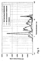
- FIG. 3 shows the impedance spectrum (Nyquist plot) of a pore-forming cathode (black circles) and a reference cathode (gray triangles) in a half-cell measurement in which the electrodes were filled with a standard electrolyte quantity of 0.42 x the nickel deposition amount.
- the impedance spectra were measured by measurements in a cathode half cell test stand (cf.
- FIG. 4 shows the difference in mean cell voltage of these two cell groups at different cell temperatures between 630 ° C and 648 ° C.
- the cells with pore-forming cathodes show a better performance in all cases than the cells with reference cathodes.
- the cell voltage difference varies with a current density of 120mA / cm 2 between 25mV and 30mV. It should be noted that the cell voltage difference increases with decreasing temperature.
- FIG. 5 shows the pore spectra for one reference electrode (black, solid) and two electrodes with pore formers, one with the carbon fiber C10M250UNS (gray) and the other with the carbon fiber C25M350UNS (black, dashed).
- the pore-forming cathodes were prepared by the above-described recipe. All three cathodes were measured in the burned-out state, ie after residue-free combustion of the carbon fibers. It it becomes clear that in the reference cathode, pores with a diameter of 1 ⁇ m to 3 ⁇ m are mainly present.
- FIG. 6 shows the impedance spectrum (Nyquist plot) of a pore-forming cathode (circles or diamond symbols) and a reference cathode (gray triangles) in a half-cell measurement, as for FIG. 3 already described.
- the pore former cathode was filled with different amounts of electrolyte from 0.32 to 0.52 x the nickel coverage.
- the reference cathode was filled with a standard electrolyte amount of 0.42 ⁇ the nickel deposition amount.
- the impedance spectra were obtained in measurements in a cathode half cell test stand (see description of FIG. 3 ). In each case two identical cathodes were used per half-cell test (once as a working cathode and once as a counterelectrode).
Landscapes
- Chemical & Material Sciences (AREA)
- Chemical Kinetics & Catalysis (AREA)
- Electrochemistry (AREA)
- General Chemical & Material Sciences (AREA)
- Engineering & Computer Science (AREA)
- Materials Engineering (AREA)
- Ceramic Engineering (AREA)
- Manufacturing & Machinery (AREA)
- Structural Engineering (AREA)
- Organic Chemistry (AREA)
- Sustainable Development (AREA)
- Sustainable Energy (AREA)
- Life Sciences & Earth Sciences (AREA)
- Inert Electrodes (AREA)
- Fuel Cell (AREA)
Description
- Die vorliegende Erfindung betrifft ein Verfahren zur Herstellung einer Elektrode für eine Schmelzkarbonat-Brennstoffzelle, mit einer elektrochemisch aktiven, mit Hohlräumen versehenen Elektrodenschicht, wobei zur Herstellung einer elektrochemisch aktiven Elektrodenschicht eine Mischung hergestellt wird, die mindestens ein aus ersten Partikeln bestehendes Elektrodenmaterial für das Elektrodengerüst, mindestens ein Porenbildnermaterial und mindestens ein Bindemittel enthält, und wobei der resultierende Grünling erhitzt wird, so dass das mindestens eine Porenbildnermaterial und das mindestens eine Bindemittel ausgebrannt werden.
- Brennstoffzellen sind Primärelemente, in denen eine chemische Reaktion zwischen einem Gas und einem Elektrolyten stattfindet. Im Prinzip wird in Umkehrung der Elektrolyse von Wasser ein wasserstoffhaltiges Brenngas an eine Anode und ein sauerstoffhaltiges Kathodengas an eine Kathode herangeführt und zu Wasser umgesetzt. Die freiwerdende Energie wird als elektrische Energie entnommen.
- Schmelzkarbonat-Brennstoffzellen (Molten Carbonate Fuel Cells, MCFC) sind bspw. in der
DE 43 03 136 C1 und derDE 195 15 457 C1 beschrieben. Sie bestehen in ihrem elektrochemisch aktiven Bereich aus einer Anode, einer Elektrolytmatrix und einer Kathode. Als Elektrolyt dient eine Schmelze aus einem oder mehreren Alkalimetallkarbonaten, die in eine feinporöse Elektrolytmatrix aufgenommen ist. Der Elektrolyt trennt die Anode von der Kathode und dichtet die Gasräume von Anode und Kathode gegeneinander ab. Beim Betrieb einer Schmelzkarbonat-Brennstoffzelle wird der Kathode ein Sauerstoff und Kohlendioxid enthaltendes Gasgemisch, meist Luft und Kohlendioxid, zugeführt. Der Sauerstoff wird reduziert und mit dem Kohlendioxid zu Karbonationen umgesetzt, die in den Elektrolyten wandern. Der Anode wird wasserstoffhaltiges Brenngas zugeführt, wobei der Wasserstoff oxidiert und mit den Karbonationen aus der Schmelze zu Wasser und Kohlendioxid umgesetzt wird. Das Kohlendioxid wird in einem Kreislauf in die Kathode zurückgeführt. Die Oxidation des Brennstoffs und die Reduktion des Sauerstoffs laufen also getrennt voneinander ab. Die Betriebstemperatur liegt in der Regel zwischen 550°C und 750°C. MCFC-Zellen transformieren die im Brennstoff gebundene chemische Energie also direkt und effizient in elektrische Energie. - Eine konventionelle Kathode besteht aus einer elektrochemisch aktiven Elektrodenschicht aus Nickeloxid, die zum Beispiel mittels sog. Coating-Verfahren hergestellt wird. Dabei wird ein Gemisch aus feinen, pulverförmigen Nickelfilamenten und polymeren Bindemitteln auf ein stabilisierendes Elektrodensubstrat, einen Kathodenschaum (bspw. Nickelschaum) aufgebracht. Die Auftragsmenge wird durch das gewünschte Nickelgewicht pro Flächeneinheit der Kathode bestimmt. Wenn die fertige MCFC-Zelle erstmals angefahren und auf Betriebstemperatur gebracht wird, werden die polymeren Bindemittel ausgebrannt und das sowohl im Kathodenschaum als auch in der elektrochemisch aktiven Elektrodenschicht enthaltene metallische Nickel zu Nickeloxid oxidiert.
- Andere Verfahren zur Herstellung von MCFC-Kathoden verarbeiten eine Pulverschüttung trocken nach dem "dry doctoring-Verfahren" und einem Sinterprozess zu einer metallischen, mikroporösen Elektrodenschicht. Auch diese werden im Anfahren der MCFC zu einer porösen Nickeloxidkomponente oxidiert, wobei jedoch kein Bindemittel ausgebrannt wird.
- Die beim Betrieb der MCFC-Zelle ablaufende Kathodenreaktion, bei der Sauerstoff reduziert und mit Kohlendioxid zu Karbonationen umgesetzt wird, die in den Elektrolyten wandern, ist ein sehr komplexer Prozess, da daran die drei Phasen Elektrode, Kathodengas und Elektrolyt beteiligt sind. Daher ist die Morphologie der Kathode ein wesentlicher Faktor für eine optimal ablaufende Kathodenreaktion. Ein Aspekt der Morphologie der Kathode ist die Porosität der elektrochemisch aktiven Kathodenschicht. Diese Porosität ist im Prinzip das Resultat des Ausbrennens der Bindemittel, wobei Hohlräume zurückbleiben, die letztendlich von der Art der für das Ausgangsmaterial verwendeten Partikel abhängt. In dem Fall, dass als Augangsmaterial für die Herstellung pulverförmige Nickelfilamente und ein Bindemittel verwendet wird, gibt es keine Möglichkeit, Größe und Verteilung der entstehenden Poren aktiv zu kontrollieren.
- In der Regel wird eine bimodale Porenverteilung angestrebt, bei welcher Poren mit zwei unterschiedlichen Porengrößen nebeneinander in der elektrochemisch aktiven Kathodenschicht existieren. Im Betrieb dienen die größeren Poren (im Folgenden: Gastransportporen) dem Gastransport innerhalb der Elektrode, während in den kleineren, mit geschmolzenem Elektrolyten gefüllten Poren (im Folgenden: Reaktionsporen) die elektrochemische Reaktion stattfindet.
- Die
US 4 150 076 offenbart eine Brennstoffzellenelektrode und ein Verfahren zu deren Herstellung, bei dem erste Partikel (Katalysator) mit CO-Agglomeraten aus zweiten Partikeln, Bindemittel und Porenbildnermaterial gemischt werden. - Im Stand der Technik sind Verfahren bekannt, mit denen die Größe und Verteilung der entstehenden Poren aktiv kontrolliert werden sollen. Die
DE 1 907 326 A1 beschreibt ein Verfahren, bei dem zur Herstellung eines Elektrodenmaterials ein Porenbildner, der sich beim Sintern verflüchtigt, in einer Kugelmühle auf eine Teilchengröße von ca. 5µm bis 25µm zerkleinert und unmittelbar anschließend Nickelpulver in der Kugelmühle untergemischt wird. Dadurch soll in der fertigen Elektrode eine gleichmäßig feine Porenstruktur erreicht werden. DieUS 4,410,607 offenbart ein Verfahren zur Herstellung einer Elektrode mit einer bimodalen Porenverteilung, d.h. mit einer Verteilung von kleinen und großen Poren, bei dem feines Nickeloxid mit einem Bindemittel vermischt und anschließend zu großen, agglomerierten Partikeln vermahlen wird. - Diese Verfahren haben gemeinsam, dass sowohl die Größe als auch die Verteilung der Poren nicht unmittelbar, sondern nur mittelbar von der Wahl der Ausgangsmaterialien, insbesondere der Wahl der Partikel für das Elektrodenmaterial, beeinflusst werden können, d. h. in Abhängigkeit des gewählten Ausgangsmaterials stellt sich ein zugehöriges Porenspektrum selbsttätig ein. Die Größe der Partikel des Elektrodenausgangsmaterials kann im Hinblick auf die Leistung aber nicht frei gewählt werden. Die Leistung der im Stand der Technik bekannten Elektroden ist begrenzend für die Leistungsdichte des Gesamtsystems einer MCFC-Zelle, und die Leistung der Elektroden hängt wiederum in erster Linie von ihrem Porenspektrum, d. h. der Größe und Verteilung der einzelnen Poren ab. Die Lebensdauer einer MCFC-Zelle wird ferner entscheidend von der eingebrachten Elektrolytmenge beeinflusst, die ebenfalls von Größe und Zahl der Reaktionsporen abhängt.Die Menge des in die mikroporösen Elektroden ohne Leistungsverlust einbringbaren Elektrolyten ist stark von Größe und Verteilung der Poren der MCFC-Elektroden abhängig.
- Die Aufgabe der vorliegenden Erfindung besteht somit darin, ein Verfahren zur Herstellung einer Elektrode der o.g. Art vorzuschlagen, deren Porenspektrum im Hinblick auf Leistungsdichte und Lebensdauer von MCFC-Zellen optimiert ist.
- Die Lösung besteht in einem Verfahren mit den Merkmalen des Anspruchs 1. Das erfindungsgemäße Verfahren zeichnet sich dadurch aus, dass in die Mischung zusätzlich mindestens ein Abbildungsmaterial in Form von zweiten Partikeln oder ein beim Trocknen oder Erwärmen der Mischung zweite Partikel ergebendes Material eingebracht wird, und zwar in einer solchen Menge und Größe, dass das Abbildungsmaterial das Porenbildnermaterial zumindest zu einem großen Teil umkleidet, und dass nach dem Ausbrennen von dem Abbildungsmaterial begrenzte Hohlräume zurückbleiben. Die zweiten Partikel sind dabei kleiner als erste Partikel, aus dem das Elektrodenmaterial besteht und kleiner als die Partikel des Porenbildnermaterials.
- Zusätzlich zum Elektrodenmaterial und zum Porenbildnermaterial wird also ein sog. Abbildungsmaterial in die Mischung zur Herstellung einer Elektrode gegeben. Das Abbildungsmaterial dient dazu, die Partikel des Porenbildnermaterials in der Mischung zumindest zu einem großen Teil zu umkleiden. Nach dem Ausbrennen des Porenbildnermaterials verbleibt gewissermaßen eine "Negativform" des umkleideten Partikels, also ein vom Abbildungsmaterial umschlossener Hohlraum, der als Gastransportpore oder Reaktionspore dient.
- Das erfindungsgemäße Verfahren ermöglicht es, dass das Porenspektrum aktiv und unmittelbar beeinflusst werden kann, so dass das Porenspektrum unabhängig von der Größe der ersten Partikel des Elektrodenausgangsmaterials im Hinblick auf Leistungsdichte und Lebensdauer einer MCFC-Zelle gezielt und kontrollierbar optimiert werden kann. Insbesondere können Reaktionsporen dargestellt werden, die kleiner sind, als es durch die Wahl des Ausgangsmaterials für die ersten Partikel nur möglich wäre. Die Leistung der erfindungsgemäßen Elektrode mit optimiertem Porenspektrum ist gegenüber dem Stand der Technik deutlich erhöht, da der Polarisationswiderstand signifikant abgesenkt ist. Die Toleranz für höhere Elektrolytfüllgrade ist ohne Leistungseinbußen deutlich gesteigert, so dass die Lebensdauer wesentlich erhöht ist. Die Erhöhung der Leistungsdichte und Standzeit einer mit erfindungsgemäßen Elektroden bestückten MCFC-Zelle führt direkt zu einer wesentlichen Kostenersparnis sowohl in Bezug auf den Zellstapel als auch auf das Gesamtsystem der Brennstoffzelle. Vorteilhafte Weiterbildungen ergeben sich aus den Unteransprüchen.
- Die nach dem erfindungsgemäßen Verfahren hergestellte Elektrode besitzt ein Porenspektrum, das eine Häufung des durch die zweiten Partikel abgebildeten Porenbildnermaterials als Poren aufweist.
- Die das Abbildungsmaterial darstellenden zweiten Partikel begrenzen Hohlräume, die als Gastransportporen und/oder Reaktionsporen dienen.
- Als Porenbildnermaterial für die (größeren) Gastransportporen werden vorzugsweise Substanzen gewählt, die spätestens bei Erreichen der Betriebstemperatur der MCFC-Brennstoffzelle (ca. 600°C bis 650°C) rückstandsfrei ausbrennen. Derartige Porenbildner sind dem Fachmann bekannt. Mögliche Porenbildner sind bspw. verschiedene Arten von Fasern, wobei sowohl verzweigte Fasern als auch unverzweigte Fasern zum Einsatz kommen können. Der Durchmesser der Fasern kann bspw. zwischen 5µm und 50µm liegen, wobei ein Bereich von 5µm bis 20µm bevorzugt ist. Die Länge der Fasern kann bspw. 10µm bis 500µm, vorzugsweise 100µm bis 200µm betragen. Geeignete Fasern sind bspw. Polyethylenfasern, Cellulosefasern, Karbonfasern jeglicher Art, Fasern aus karbonisiertem Polyacrylnitrit, Fasern auf Nylonbasis, Seidenfasern und jede vergleichbare Faserart.
- Als Porenbildnermaterial für die (kleineren) Reaktionsporen werden vorzugsweise ebenfalls Substanzen gewählt, die spätestens bei Erreichen der Betriebstemperatur der MCFC-Brennstoffzelle (ca. 600°C bis 650°C) rückstandsfrei ausbrennen. Derartige Porenbildner sind dem Fachmann bekannt. Bevorzugt sind Porenbildner, die eine sphärische oder spratzige Form aufweisen. Der Durchmesser der Porenbildner kann bspw. zwischen 1µm und 5µm liegen, wobei ein Wert von 3µm bevorzugt ist. Unter dem Durchmesser der Porenbilner wird der mittlere Durchmesser eines das Porenbilnerpartikel gedanklich einhüllenden Körpers verstanden. Ohne Anspruch auf Vollständigkeit sind folgende Stoffe als Porenbildner für elektrolytgefüllte Reaktionsporen denkbar: Graphitpulver und -stäube, Rußpulver und -stäube, Kohlenstoffpulver und - stäube, Salze, welche sich im Elektrolyten lösen oder als Elektrolyt dienen, Harzemulsionen, Wachsemulsionen, organische Pigmente sowie jegliche Art von Zuckerverbindungen und Stärken.
- Das sog. Abbildungsmaterial, das sind die zweiten Partikel, dient dazu, die Partikel aus den Porenbildnermaterialien zumindest zu einem großen Teil zu umkleiden. Wenn die Porenbildnermaterialien rückstandsfrei ausgebrannt sind, bleibt das Abbildungsmaterial zurück und umschließt einen Hohlraum, der zuvor von dem jeweiligen Partikel ausgefüllt war. Mit anderen Worten: Die vom Porenbildnermaterial gebildete Pore ist im Ausgangsmaterial durch das Abbildungsmaterial abgebildet. Das bedeutet, dass die Pore, d. h. der vom Abbildungsmaterial umschlossene Hohlraum einen Durchmesser aufweist, der dem Durchmesser des zuvor vorhandenen Partikel aus Porenbildnermaterial entspricht. Damit können Poren definierter Größe und definierter Menge erzeugt werden, die eine optimale Leistung ergeben. Insbesondere Können Poren erzeugt werden, die nicht von der Art der ersten Partikel abhängen, die das Elektrodengrundgerüsts bilden (welche sich aus dem Filamentpulver ergeben).
- Als Abbildungsmaterial eignen sich bspw. Partikel, die von Hause aus oder nach dem Ausbrennen des Porenbildnermaterials eine sphärische, würfelförmige oder spratzige Form und vorteilhafterweise einen Partikeldurchmesser bis zu 3µm, vorzugsweise von weniger als 1µm aufweisen. Unter Partikeldurchmesser wird der mittlere Durchmesser eines das von Natur aus unregelmäßige Partikel gedanklich einhüllenden Körpers verstanden. Geeignet sind insbesondere Metallpulver, Metalloxidpulver, Metalloxidhydrate sowie anorganische oder organische Metallsalze. Beispielhaft dafür stehen pyrolysierbare Nickelverbindungen wie zum Beispiel Nickelsalze, bevorzugt Nickelnitrat oder Nickelacetat, die beim Trocknen oder Erwärmen entsprechende Partikel bilden. Eine in-situ-Erzeugung des Nickelsalzes durch Zugabe von Säure (bevorzugt Essigsäure oder Salpetersäure) zur nickelhaltigen Mischung, bspw. zum nickelhaltigen Schlicker, ist ebenfalls möglich. Als Abbildungsmaterial ist auch feines oder ultrafeines Nickeloxidpulver geeignet. Schließlich eignen sich auch Nickeloxidhydrat-Präparate, welche in an sich bekannter Weise durch Fällung aus nickelhaltigen Lösungen erhalten werden können. Das Abbildungsmaterial kann auch aus dem Material für das Elektrodengerüst (d.h. der aktiven Elektrodenschicht) bestehen, jedoch kleiner, was die Partikelgröße anbetrifft, in Form eines vorzugsweise feinen oder ultrafeinen Pulvers.
- Das Verhältnis von Nickel (Gesamtmenge) zu Porenbildnermaterial bewegt sich vorzugsweise in einem Bereich von 1:1 bis 10:1 Gewichtsteilen. Insbesondere das als Abbildungsmaterial geeignete Nickeloxidpulver weist sphärische oder würfelförmige Partikel mit einer definierten Größe auf, so dass diese Berechnung einfach durchzuführen ist. Der Gewichtsanteil des notwendigen Abbildungsmaterials bewegt sich dabei in der Regel in einem Bereich von 3 bis 15 Gew.-% bezogen auf die Gesamtmenge der herzustellenden Mischung. Die Menge des Abbildungsmaterials kann vorzugsweise derart gewählt werden, dass eine zumindest nahezu vollständige Umkleidung der Partikel des Porenbildnermaterials möglich ist.
- Die Menge des Abbildungsmaterials wird von den Abmessungen der (ersten) Partikel des verwendeten Abbildungsmaterials und den Abmessungen des Porenbildnermaterials bestimmt. Diese Abmessung folgt für jeden Typ von Abbildungsmaterial einer bestimmten statistischen Verteilung, so dass die notwendige Menge an Abbildungsmaterial (abhängig von der Abmessung der Partikel und Größe der zu umkleidenden Oberfläche) erfahrungsgemäß gut bestimmt werden kann. Das heißt, dass auch bei einer homogenen Verteilung ausreichend viele zweite Partikel vorhanden sind, dass eine weitgehend vollständige Umkleidung der Partikel des Porenbildnermaterials möglich ist. Tatsächlich ist aber davon auszugehen, dass die Menge der Anlagerung nicht nur allein von der statistischen Verteilung der Partikel bestimmt ist, vielmehr spielen auch Adhäsionskräfte eine Rolle. In einer Suspension enthaltene Partikel neigen nämlich dazu, Agglomerate zu bilden, einfach , deshalb, weil kleine Teilchen aufgrund von molekularen Anziehungskräften sich an größere Teilchen anlagern. Zur gezielten Steuerung der Anlagerung kann das Porenbildnermaterial und das Abbildungsmaterial, das partikelförmig oder als Lösung vorliegen kann, miteinander vermischt werden, bevor sie mit weiteren Materialien im Elektrodenschlicker verarbeitet werden. Sofern eine Lösung vorliegt, werden geeignete Partikel beim Trocknen oder Erwärmen des Grünlings gebildet.
- Das Elektrodenmaterial, das Porenbildnermaterial und das Abbildungsmaterial können zusammen in dem Fachmann bekannter Weise zu einem Elektrodenschlicker verarbeitet werden. Wie erwähnt, können das Porenbildnermaterial und das Abbildungsmaterial in vorteilhafter Weise aber auch vorab miteinander vermischt werden, da dann die Umkleidung des Porenbildnermaterials mit dem Abbildungsmaterial vereinfacht wird.
- Die vorliegende Erfindung ist nicht auf wässrige Systeme beschränkt, sondern kann bspw. auch auf alkoholische Systeme angewandt werden, wobei hier keine Nickelsalze, sondern bspw. Nickeloxidpartikel als Abbildungsmaterial verwendet werden.
- Die vorliegende Erfindung ist ferner nicht auf Elektroden beschränkt, die aus einem Nickel-Schlickersystem hergestellt werden. Sie eignet sich vielmehr bspw. auch für Elektroden, die durch Pulverpressung hergestellt werden (sog. "Dry-Doctoring"-Systeme). Dabei wird das Porenbildnermaterial vor der Einbringung in die trockene Pulvermischung mit dem Abbildungsmaterial umkleidet, bspw. in einem vorhergehenden Imprägnierungs- oder Mischungsschritt o. dgl..
- Ausführungsbeispiele der vorliegenden Erfindung werden im Folgenden anhand der beigefügten Zeichnungen näher beschrieben. Es zeigen in einer schematischen, nicht maßstabsgetreuen Darstellung:
- Figur 1
- eine Darstellung einer Gastransportpore in einer erfindungsgemäßen Elektrode;
- Figur 2
- eine Darstellung von Reaktionsporen in einer erfindungsgemäßen Elektrode;
- Figur 3
- Impedanzspektren einer ersten Ausführungsform einer erfindungsgemäßen Elektrode sowie einer Referenzelektrode;
- Figur 4
- eine graphische Darstellung der Spannungsunterschiede in Laborstapeln zwischen Zellen mit erfindungsgemäßen Elektroden und Zellen mit Referenzelektroden;
- Figur 5
- ein Porenspektrum einer erfindungsgemäßen Elektrode sowie einer Referenzelektrode;
- Figur 6
- Impedanzspektren einer zweiten erfindungsgemäßen Elektrode mit unterschiedlichen Elektrolytmengen sowie einer Referenzelektrode mit einer Standardelektrolytmenge.
- Ein Ausführungsbeispiel einer erfindungsgemäßen Elektrode auf Nickelbasis kann wie folgt hergestellt werden:
- Als Ausgangsmaterial (erste Partikel) eignen sich prinzipiell alle dem Fachmann bekannten Nickelpulver. Vorzugsweise werden filamentartige Nickelpulver verwendet, wie bspw. die unter der Bezeichnung Ni-210, Ni-240, Ni-255 oder Ni-287 bekannten Nickelpulver.
- Eine beispielhafte Rezeptur für eine Elektrode mit Gastransportporen sieht wie folgt aus:
Nickelpulver (Ni210-Filamentpulver) 30-50 Gew.-% Porenbildnermaterial (Fasermaterial, karbonisiertes Polyacrylnitrit, Durchmesser etwa 5µm, Länge etwa 100µm) 5-10 Gew.-% Abbildungsmaterial Nickelacetat-Tetrahydrat 3-15 Gew.-% Wasser 10-20 Gew.-% Organische Bindemittel (Moviol, Glycerin, Agitan) Rest - Das Fasermaterial und das Nickelacetat-Tetrahydrat werden innig miteinander vermischt und die resultierende Mischung mit den restlichen Komponenten in bekannter Weise zu einem Elektrodenschlicker verarbeitet. Der Elektrodenschlicker wird auf eine Unterlage, z. B. ein Elektrodensubstrat (Nickelschaum) aufgebracht und getrocknet. Die Auftragsmenge wird durch das gewünschte Nickelgewicht pro Flächeneinheit bestimmt. Die resultierenden Grünlinge werden in an sich bekannter Weise zu einer Kathode für eine MCFC-Brennstoffzelle verarbeitet. Beim Anfahren der Brennstoffzelle werden die organischen Bindemittel und das Porenbildnermaterial ausgebrannt, und das Nickel des Nickelschaums und der elektrochemisch aktiven Schicht wird zu Nickeloxid oxidiert. Das Nickelacetattetrahydrat wird zu Nickeloxid umgewandelt.
- Die
Figuren 1 und2 zeigen beispielhaft die Struktur der aus dem beschriebenen Verfahren resultierenden Elektroden.Figur 1 zeigt eine elektrochemisch aktive Schicht 10 mit ersten Partikeln, nämlich Nickeloxidpartikeln 11. Ein länglicher Hohlraum 12 wird ursprünglich durch die als Porenbildner geeigneten Materialien (hier Fasern) gebildet und durch zweite Partikel, nämlich feinste Nickeloxidpartikel 13 begrenzt und dient als Gastransportpore. Die ersten Partikel 11 sind größer als die zweiten Partikel. Eine solche Struktur entsteht bspw. mit der oben angegebenen Rezeptur. -
Figur 2 zeigt in vergleichbarer Weise eine elektrochemisch aktive Schicht 20 mit (ersten) Nickeloxidpartikeln 11. Zahlreiche sphärische Hohlräume 22 werden durch feinste (zweite) Nickeloxidpartikel 23 begrenzt und dienen als Reaktionsporen. Die Herstellung erfolgt entsprechend der oben angegebenen Rezeptur, wobei das oben angegebene Porenbildnermaterial durch ein für die Herstellung von Reaktionsporen geeignetes Porenbildnermaterial ersetzt wird. Es fällt auf, dass der Durchmesser der Hohlräume 22 kleiner ist als die Hohlräume, welche die ersten Nickeloxidpartikel 11 selbst bilden, die das Elektrodengerüst darstellen. Eine solche Struktur kann mit den im Stand der Technik bekannten Verfahren nicht hergestellt werden. - Selbstverständlich kann die oben angegebene Rezeptur zugleich Porenbildnermaterialien sowohl für die Herstellung von Gastransportporen als auch für die Herstellung von Reaktionsporen enthalten. Dann entsteht eine elektrochemisch aktive Schicht mit bimodaler Struktur/Porenverteilung, d.h. Poren verschiedener Größe, deren Größe und Verteilung in der elektrochemisch aktiven Schicht durch die Auswahl der Porenbildnermaterialien und ihre Umkleidung mit dem Abbildungsmaterial aktiv und unmittelbar beeinflusst werden kann. Das Verhältnis der Anzahl von Poren unterschiedlicher Art kann über das Mengenverhältnis der eingesetzten Porenbildnermaterialien gesteuert werden.
- Nach dem obigen Verfahren hergestellte erfindungsgemäße Kathoden (im Folgenden: Porenbildnerkathoden) mit gezielt eingebrachten Gastransportporen (vgl.
Figur 1 ) wurden im Vergleich zu mit herkömmlichen Verfahren hergestellten Standardkathoden (im Folgenden: Referenzkathoden) untersucht.Figur 3 zeigt das Impedanzspektrum (Nyquistplot) einer Porenbildnerkathode (schwarze Kreise) und einer Referenzkathode (graue Dreiecke) in einer Halbzellenmessung, bei der die Elektroden mit einer Standardelektrolytmenge von 0,42 x der Nickelauftragsmenge befüllt wurden. Die Impedanzspektren wurden bei Messungen in einem Kathodenhalbzellenteststand (vgl. "Mechanistische Untersuchung und Modellierung der Kathodenreaktion in Karbonatbrennstoffzellen (MCFC)", M. Bednarz, Dissertation, Universität Hamburg 2002) erhalten. Dabei wurden pro Halbzellentest jeweils zwei identische Kathoden (einmal als Arbeitselektrode und einmal als Gegenelektrode) eingesetzt. Die Kathodenprüflinge hatten dabei jeweils eine Fläche von 9cm2. Es ist deutlich erkennbar, dass bei nahezu identischem ohmschem Widerstand (R-Ohm) von 45-50mΩ für die Porenbildnerkathode und für die Referenzelektrode der Gesamtwiderstand (R-Gesamt) für die Porenbildnerkathode mit ca. 100mΩ deutlich geringer ist als der Gesamtwiderstand für die Referenzelektrode mit ca. 140mΩ. Die Porenbildnerkathode ist also der Referenzelektrode überlegen. - Die Übertragbarkeit der Halbzellentests in die Vollzelle wurde mittels Laborstapelversuchen demonstriert. Zur Darstellung der Leistungsfähigkeit der Porenbildnerkathoden und um einen direkten Vergleich zu ermöglichen, wurde ein Laborstapel sowohl mit Porenbildnerkathoden (Gruppe 1) als auch mit Referenzkathoden (Gruppe 2) ausgerüstet.
Figur 4 zeigt den Unterschied der mittleren Zellspannung dieser beiden Zellgruppen bei verschiedenen Zelltemperaturen zwischen 630°C und 648°C. Die Zellen mit Porenbildnerkathoden zeigen in allen Fällen eine bessere Leistung als die Zellen mit Referenzkathoden. Die Zellspannungsdifferenz variiert mit einer Stromdichte von 120mA/cm2 zwischen 25mV und 30mV. Dabei ist zu bemerken, dass die Zellspannungsdifferenz mit abnehmender Temperatur zunimmt. Das bedeutet, dass die Überlegenheit der Porenbildnerkathode bei einer Absenkung der Zelltemperaturen deutlicher zu Tage tritt. Eine Absenkung der Zelltemperaturen geht mit verlängerten Stapellebenszeiten einher. Die Zellen mit Porenbildnerkathoden zeigten also bei erhöhter Lebensdauer eine bessere Leistung als die Zellen mit Referenzkathoden. -
Figur 5 zeigt die Porenspektren für eine Referenzelektrode (schwarz, durchgezogen) und zwei Elektroden mit Porenbildnern, einmal mit der Karbonfaser C10M250UNS (grau) und einmal mit der Karbonfaser C25M350UNS (schwarz, gestrichelt). Die Porenbildnerkathoden wurden im Übrigen mit der oben beschriebenen Rezeptur hergestellt. Alle drei Kathoden wurden im ausgebrannten Zustand, d. h. nach rückstandsfreier Verbrennung der Karbonfasern vermessen. Es wird deutlich, dass in der Referenzkathode in der Hauptsache Poren mit einem Durchmesser von 1µm bis 3µm vorliegen. In den beiden Porenbildnerkathoden ist ebenfalls ein Anteil kleiner Poren mit einem Durchmesser von etwa 2µm enthalten, jedoch in einem geringeren Anteil als bei der Referenzkathode. Zusätzlich sind aber auch größere Poren mit Durchmessern im Bereich von 5µm bis 10µm vorhanden. -
Figur 6 zeigt das Impedanzspektrum (Nyquistplot) einer Porenbildnerkathode (Kreise bzw. Diamantsymbole) und einer Referenzkathode (graue Dreiecke) in einer Halbzellenmessung, wie sie fürFigur 3 bereits beschrieben wurde. Die Porenbildnerkathode wurde mit unterschiedlichen Elektrolytmengen von 0,32 bis 0,52 × der Nickelauftragsmenge befüllt. Die Referenzkathode wurde mit einer Standardelektrolytmenge von 0,42 × der Nickelauftragsmenge befüllt. Die Impedanzspektren wurden bei Messungen in einem Kathodenhalbzellenteststand erhalten (vgl. Beschreibung zuFigur 3 ). Dabei wurden pro Halbzellentest jeweils zwei identische Kathoden (einmal als Arbeitskathode und einmal als Gegenelektrode) eingesetzt. Alle getesteten Kathoden besitzen sehr ähnliche ohmsche Widerstände im Bereich von 45mΩ bis 50mΩ. Eine leichte Verschiebung des ohmschen Widerstandes zu höheren Werten mit zunehmendem Elektrolytfüllgrad ist dabei üblich. Es wird jedoch deutlich, dass die Porenbildnerkathode selbst bei hohen Elektrolytbefüllungen (Gesamtwiderstand von etwa 115mΩ für die 0,52-Befüllung) noch geringere Gesamtwiderstände zeigt als die Referenzkathode, welche einen R-Gesamt von etwa 140mΩ aufweist. Bezüglich der Füllgradtoleranz bei höheren Elektrolytfüllgraden und infolgedessen auch bezüglich der Lebensdauer zeigt sich die Porenbildnerkathode damit überlegen.
Claims (16)
- Verfahren zur Herstellung einer Elektrode für eine Schmelzkarbonatbrennstoffzelle, wobei zur Herstellung einer elektrochemisch aktiven Elektrodenschicht (10, 20) eine Mischung hergestellt wird, die mindestens ein aus ersten Partikeln (11) bestehendes Elektrodenmaterial, mindestens ein Porenbildnermaterial und mindestens ein Bindemittel enthält, und wobei der resultierende Grünling erhitzt wird, so dass das mindestens eine Porenbildnermaterial und das mindestens ein Bindemittel ausgebrannt werden,
dadurch gekennzeichnet,
dass in die Mischung vor dem Ausbrennen zusätzlich mindestens ein Abbildungsmaterial in Form von zweiten Partikeln (13, 23) oder in Form eines beim Trocknen oder Erwärmen der Mischung zweite Partikel (13, 23) ergebenden Materials eingebracht wird, dass in dem Grünling die zweiten Partikel (13, 23) kleiner als die ersten Partikel (11) und kleiner als die Partikel des Porenbildnermaterials sind, dass die zweiten Partikel (13, 23) in einer solchen Menge und in einer solchen Größe eingebracht werden, dass das Abbildungsmaterial (13, 23) das Porenbildnermaterial zumindest zu einem großen Teil umkleidet, und dass nach dem Ausbrennen von dem Abbildungsmaterial begrenzte Hohlräume (12, 22) zurückbleiben. - Verfahren nach Anspruch 1,
dadurch gekennzeichnet,
dass der Grünling vor dem Erhitzen auf ein Elektrodensubstrat aufgebracht und als Elektrodensubstrat ein Metallschaum, vorzugsweise Nickelschaum, verwendet wird. - Verfahren nach Anspruch 1 oder 2,
dadurch gekennzeichnet,
dass als Porenbildnermaterial Substanzen verwendet werden, die spätestens bei Temperaturen von 600°C bis 650°C rückstandsfrei ausbrennen. - Verfahren nach einem der Ansprüche 1 bis 3,
dadurch gekennzeichnet,
dass als Porenbildnermaterial verzweigte oder unverzweigte Fasern ausgewählt werden, die einen Durchmesser von 5µm bis 50µm, vorzugsweise 5µm bis 20µm, und/oder eine Länge von 10µm bis 500µm, vorzugsweise 100µm bis 200µm, aufweisen. - Verfahren nach einem der Ansprüche 1 bis 3,
dadurch gekennzeichnet,
dass als Porenbildnermaterial Partikel mit einer sphärischen oder spratzigen Form ausgewählt werden, die einen Durchmesser von 1µm bis 5µm, vorzugsweise 3µm, aufweisen. - Verfahren nach einem der Ansprüche 1 bis 5,
dadurch gekennzeichnet,
dass als Abbildungsmaterial Partikel mit einer sphärischen, würfelförmigen oder spratzigen Form ausgewählt werden, die insbesondere einen Durchmesser von bis zu 3µm, vorzugsweise unter 1µm, aufweisen. - Verfahren nach einem der Ansprüche 1 bis 6,
dadurch gekennzeichnet,
dass die ersten Partikel (11) eine Größe von 10µm bis 40µm haben. - Verfahren nach einem der Ansprüche 1 bis 7,
dadurch gekennzeichnet,
dass als Abbildungsmaterial Metallpulver, Metalloxidpulver, Metalloxidhydrate, anorganische oder organische Metallsalze verwendet werden. - Verfahren nach Anspruch 8,
dadurch gekennzeichnet,
dass als Abbildungsmaterial pyrolisierbare Nickelverbindungen verwendet werden. - Verfahren nach Anspruch 9,
dadurch gekennzeichnet,
dass pyrolisierbare Nickelsalze, vorzugsweise Nickelnitrat oder Nickelacetat, verwendet werden. - Verfahren nach Anspruch 10,
dadurch gekennzeichnet,
dass die Nickelsalze in situ durch Zugabe von Säure, vorzugsweise Essigsäure oder Salpetersäure, zur nickelhaltigen Mischung erzeugt werden. - Verfahren nach Anspruch 8,
dadurch gekennzeichnet,
dass feines oder ultrafeines Metalloxidpulver, insbesondere Nickeloxidpulver, verwendet wird. - Verfahren nach einem der Ansprüche 1 bis 12,
dadurch gekennzeichnet,
dass das Abbildungsmaterial in einem Anteil von 3 Gew.-% bis 15 Gew.-% bezogen auf die Gesamtmenge der Mischung zugegeben wird. - Verfahren nach einem der Ansprüche 1 bis 13,
dadurch gekennzeichnet,
dass das Porenbildnermaterial und das Abbildungsmaterial zunächst miteinander vermischt werden und dann mit dem mindestens einen Elektrodenmaterial und dem mindestens einen Bindemittel zu der Mischung verarbeitet werden. - Verfahren nach einem der Ansprüche 1 bis 14,
dadurch gekennzeichnet,
dass die Mischung als Elektrodenschlicker oder aus einer Pulvermischung hergestellt wird. - Verfahren nach einem der Ansprüche 1 bis 15,
dadurch gekennzeichnet,
dass die Mischung als wässriges oder alkoholisches System hergestellt wird.
Applications Claiming Priority (3)
| Application Number | Priority Date | Filing Date | Title |
|---|---|---|---|
| DE102006036849 | 2006-08-07 | ||
| DE102006047823A DE102006047823A1 (de) | 2006-08-07 | 2006-10-10 | Elektrode für eine Schmelzkarbonat-Brennstollzelle und Verfahren zu ihrer Herstellung |
| PCT/EP2007/006804 WO2008017409A1 (de) | 2006-08-07 | 2007-08-01 | Elektrode für eine schmelzkarbonat-brennstoffzelle und verfahren zu ihrer herstellung |
Publications (2)
| Publication Number | Publication Date |
|---|---|
| EP2050155A1 EP2050155A1 (de) | 2009-04-22 |
| EP2050155B1 true EP2050155B1 (de) | 2010-12-22 |
Family
ID=38650003
Family Applications (1)
| Application Number | Title | Priority Date | Filing Date |
|---|---|---|---|
| EP07786491A Not-in-force EP2050155B1 (de) | 2006-08-07 | 2007-08-01 | Elektrode für eine schmelzkarbonat-brennstoffzelle und verfahren zu ihrer herstellung |
Country Status (9)
| Country | Link |
|---|---|
| US (1) | US20110033771A1 (de) |
| EP (1) | EP2050155B1 (de) |
| JP (1) | JP5280358B2 (de) |
| KR (1) | KR101392712B1 (de) |
| CN (1) | CN101501901B (de) |
| AT (1) | ATE492916T1 (de) |
| CA (1) | CA2660214A1 (de) |
| DE (2) | DE102006047823A1 (de) |
| WO (1) | WO2008017409A1 (de) |
Families Citing this family (13)
| Publication number | Priority date | Publication date | Assignee | Title |
|---|---|---|---|---|
| DE102009050435A1 (de) | 2009-08-13 | 2011-02-17 | Mtu Onsite Energy Gmbh | Elektrode für eine Schmelzkarbonat-Brennstoffzelle und Verfahren zu ihrer Herstellung |
| KR101298622B1 (ko) * | 2010-05-06 | 2013-08-26 | 두산중공업 주식회사 | 연료전지용 전극체 |
| DE102017206693A1 (de) * | 2017-04-20 | 2018-10-25 | Robert Bosch Gmbh | Verfahren zur Herstellung einer Funktionsschicht |
| DE102018207773A1 (de) * | 2018-05-17 | 2019-11-21 | Robert Bosch Gmbh | Verfahren zur Herstellung poröser Elektroden für elektrochemische Zellen |
| WO2020112774A1 (en) | 2018-11-30 | 2020-06-04 | Exxonmobil Research And Engineering Company | Elevated pressure operation of molten carbonate fuel cells with enhanced co2 utilization |
| WO2020112806A1 (en) * | 2018-11-30 | 2020-06-04 | Exxonmobil Research And Engineering Company | Layered cathode for molten carbonate fuel cell |
| US11476486B2 (en) | 2018-11-30 | 2022-10-18 | ExxonMobil Technology and Engineering Company | Fuel cell staging for molten carbonate fuel cells |
| WO2020112770A1 (en) | 2018-11-30 | 2020-06-04 | Exxonmobil Research And Engineering Company | Regeneration of molten carbonate fuel cells for deep co 2 capture |
| US11888187B2 (en) | 2018-11-30 | 2024-01-30 | ExxonMobil Technology and Engineering Company | Operation of molten carbonate fuel cells with enhanced CO2 utilization |
| WO2020112895A1 (en) | 2018-11-30 | 2020-06-04 | Exxonmobil Research And Engineering Company | Reforming catalyst pattern for fuel cell operated with enhanced co2 utilization |
| KR20220113681A (ko) | 2019-11-26 | 2022-08-16 | 엑손모빌 테크놀로지 앤드 엔지니어링 컴퍼니 | 연료 전지 모듈 조립체 및 이를 사용하는 시스템 |
| CA3162231A1 (en) | 2019-11-26 | 2021-06-03 | Exxonmobile Research And Engineering Company | Operation of molten carbonate fuel cells with high electrolyte fill level |
| US11978931B2 (en) | 2021-02-11 | 2024-05-07 | ExxonMobil Technology and Engineering Company | Flow baffle for molten carbonate fuel cell |
Family Cites Families (14)
| Publication number | Priority date | Publication date | Assignee | Title |
|---|---|---|---|---|
| GB963767A (en) * | 1961-05-18 | 1964-07-15 | Leesona Corp | Improvements in or relating to fuel cells |
| US4058482A (en) * | 1976-12-20 | 1977-11-15 | United Technologies Corporation | Fuel cell electrode |
| US4708917A (en) * | 1985-12-23 | 1987-11-24 | International Fuel Cells Corporation | Molten carbonate cathodes and method of fabricating |
| JPS62154576A (ja) * | 1985-12-27 | 1987-07-09 | Fuji Electric Corp Res & Dev Ltd | 溶融炭酸塩燃料電池の製造方法 |
| JPS6324558A (ja) * | 1986-07-16 | 1988-02-01 | Hitachi Zosen Corp | 溶融炭酸塩型燃料電池用電極の製造方法 |
| US4780437A (en) * | 1987-02-11 | 1988-10-25 | The United States Of America As Represented By The United States Department Of Energy | Fabrication of catalytic electrodes for molten carbonate fuel cells |
| JPS6452382A (en) * | 1987-08-22 | 1989-02-28 | Fuji Electric Co Ltd | Manufacture of electrode for molten carbonate fuel cell |
| IT1241857B (it) * | 1990-06-01 | 1994-02-01 | Ansaldo Spa | Procedimento per la fabbricazione di catodi per celle a carbonati fusi |
| JPH07118327B2 (ja) * | 1990-07-07 | 1995-12-18 | 日本碍子株式会社 | 固体電解質型燃料電池及びこれに用いる多孔質電極体 |
| DE4303136C1 (de) * | 1993-02-04 | 1994-06-16 | Mtu Friedrichshafen Gmbh | Verfahren zur Herstellung von Schmelzcarbonat-Brennstoffzellen |
| JPH06290787A (ja) * | 1993-03-31 | 1994-10-18 | Youyuu Tansanengata Nenryo Denchi Hatsuden Syst Gijutsu Kenkyu Kumiai | 溶融炭酸塩型燃料電池空気極用前駆グリーンシート |
| KR0123709B1 (ko) * | 1994-08-17 | 1997-12-09 | 김광호 | 용융탄산염 연료전지용 양전극 및 그 제조방법 |
| JP3206904B2 (ja) * | 1999-09-22 | 2001-09-10 | 溶融炭酸塩型燃料電池発電システム技術研究組合 | 燃料電池の電極製造方法 |
| JP4763455B2 (ja) * | 2002-10-18 | 2011-08-31 | モンサント テクノロジー エルエルシー | アルコール改質のための金属支持銅触媒の使用 |
-
2006
- 2006-10-10 DE DE102006047823A patent/DE102006047823A1/de not_active Withdrawn
-
2007
- 2007-08-01 KR KR1020097004757A patent/KR101392712B1/ko not_active IP Right Cessation
- 2007-08-01 EP EP07786491A patent/EP2050155B1/de not_active Not-in-force
- 2007-08-01 CA CA002660214A patent/CA2660214A1/en not_active Abandoned
- 2007-08-01 DE DE502007006043T patent/DE502007006043D1/de active Active
- 2007-08-01 JP JP2009523179A patent/JP5280358B2/ja not_active Expired - Fee Related
- 2007-08-01 CN CN200780029221XA patent/CN101501901B/zh not_active Expired - Fee Related
- 2007-08-01 AT AT07786491T patent/ATE492916T1/de active
- 2007-08-01 WO PCT/EP2007/006804 patent/WO2008017409A1/de active Application Filing
- 2007-08-01 US US12/376,357 patent/US20110033771A1/en not_active Abandoned
Also Published As
| Publication number | Publication date |
|---|---|
| DE102006047823A1 (de) | 2008-02-14 |
| KR20090064373A (ko) | 2009-06-18 |
| JP5280358B2 (ja) | 2013-09-04 |
| CA2660214A1 (en) | 2008-02-14 |
| CN101501901B (zh) | 2011-07-06 |
| US20110033771A1 (en) | 2011-02-10 |
| CN101501901A (zh) | 2009-08-05 |
| EP2050155A1 (de) | 2009-04-22 |
| JP2010500705A (ja) | 2010-01-07 |
| WO2008017409A1 (de) | 2008-02-14 |
| KR101392712B1 (ko) | 2014-05-12 |
| DE502007006043D1 (de) | 2011-02-03 |
| ATE492916T1 (de) | 2011-01-15 |
Similar Documents
| Publication | Publication Date | Title |
|---|---|---|
| EP2050155B1 (de) | Elektrode für eine schmelzkarbonat-brennstoffzelle und verfahren zu ihrer herstellung | |
| EP1343215B1 (de) | Strukturierter Körper für eine in Brennstoffzellen verwendete Anode | |
| EP2759009B1 (de) | Gasdiffusionsschicht mit verbesserter elektrischer leitfähigkeit und gasdurchlässigkeit | |
| DE2720529C2 (de) | Verfahren zur Herstellung einer Brennstoffzellenelektrode | |
| DE112006000220T5 (de) | Zelle für Festoxid-Brennstoffzelle und Verfahren zur Herstellung einer Zelle für Festoxid-Brennstoffzelle | |
| EP1118129B1 (de) | Gasdiffusionselektrode und verfahren zu deren herstellung | |
| DE19963882A1 (de) | Elektrode für Hochtemperatur-Brennstoffzelle und Verfahren zur Herstellung derselben | |
| EP1150369A1 (de) | Gasverteilerstrukturen und Gasdiffusionselektroden für Polymerelektrolyt-Brennstoffzellen | |
| EP1246288B1 (de) | Poröser, gasdurchlässiger Schichtunterbau zu einer dünnen, gasdichten Schicht, zur Verwendung als funktionelle Komponente in Hochtemperatur-Brennstoffzellen | |
| EP1295353B1 (de) | Verfahren zur herstellung einer elektrode mit temperaturbeständiger leitfähigkeit | |
| DE112009002616T5 (de) | Mit Elektrolyten imprägnierte verstärkte Matrix für eine Carbonatschmelzen-Brennstoffzelle und Verfahren zu deren Herstellung | |
| EP0645832B1 (de) | Negative Elektrode für gasdichte alkalische Akkumulatoren, die eine Russ enthaltende Gasverzehrschicht besitzt | |
| DE102007000325A1 (de) | Verfahren für das Herstellen eines Keramik-Stapels | |
| DE69110581T2 (de) | Verfahren zur Herstellung von Kathoden für Zellen mit geschmolzenen Karbonat-Elektrolyten. | |
| WO2010037665A1 (de) | Hochtemperatur-brennstoffzelle und zugehörige brennstoffzellenanlage | |
| DE3238824A1 (de) | Sauerstoffmessfuehlerelement und verfahren zu dessen herstellung | |
| DE19935271C2 (de) | Matrixmaterial für Brennstoffzellen sowie Verfahren zu seiner Herstellung und seine Verwendung | |
| DE102011083538A1 (de) | Speicherelement für eine Festelektrolyt-Batterie sowie Verfahren zu dessen Herstellung | |
| DE102007060272A1 (de) | Bipolarplatte und Verfahren zum Herstellen einer Schutzschicht an einer Bipolarplatte | |
| DE102017206693A1 (de) | Verfahren zur Herstellung einer Funktionsschicht | |
| EP3903373B1 (de) | Verfahren zur herstellung einer keramischen funktionsschicht | |
| DE112020001817T5 (de) | Festoxid-Brennstoffzelle, umfassend eine mit alkalibasiertem Promotor beladene Anode | |
| EP4198175A2 (de) | Trägergestützter elektrolyt, verfahren zu seiner herstellung und seine verwendung | |
| WO2011018202A2 (de) | Elektrode für eine schmelzkarbonat-brennstoffzelle und verfahren zu ihrer herstellung | |
| DE102023108103A1 (de) | Brennstoffzellenkathode, verfahren zu deren herstellung und brennstoffzelle |
Legal Events
| Date | Code | Title | Description |
|---|---|---|---|
| PUAI | Public reference made under article 153(3) epc to a published international application that has entered the european phase |
Free format text: ORIGINAL CODE: 0009012 |
|
| 17P | Request for examination filed |
Effective date: 20090209 |
|
| AK | Designated contracting states |
Kind code of ref document: A1 Designated state(s): AT BE BG CH CY CZ DE DK EE ES FI FR GB GR HU IE IS IT LI LT LU LV MC MT NL PL PT RO SE SI SK TR |
|
| AX | Request for extension of the european patent |
Extension state: AL BA HR MK RS |
|
| 17Q | First examination report despatched |
Effective date: 20090511 |
|
| GRAP | Despatch of communication of intention to grant a patent |
Free format text: ORIGINAL CODE: EPIDOSNIGR1 |
|
| GRAS | Grant fee paid |
Free format text: ORIGINAL CODE: EPIDOSNIGR3 |
|
| GRAA | (expected) grant |
Free format text: ORIGINAL CODE: 0009210 |
|
| AK | Designated contracting states |
Kind code of ref document: B1 Designated state(s): AT BE BG CH CY CZ DE DK EE ES FI FR GB GR HU IE IS IT LI LT LU LV MC MT NL PL PT RO SE SI SK TR |
|
| REG | Reference to a national code |
Ref country code: GB Ref legal event code: FG4D Free format text: NOT ENGLISH |
|
| REG | Reference to a national code |
Ref country code: CH Ref legal event code: EP |
|
| REG | Reference to a national code |
Ref country code: IE Ref legal event code: FG4D |
|
| REF | Corresponds to: |
Ref document number: 502007006043 Country of ref document: DE Date of ref document: 20110203 Kind code of ref document: P |
|
| REG | Reference to a national code |
Ref country code: DE Ref legal event code: R096 Ref document number: 502007006043 Country of ref document: DE Effective date: 20110203 |
|
| REG | Reference to a national code |
Ref country code: NL Ref legal event code: T3 |
|
| REG | Reference to a national code |
Ref country code: ES Ref legal event code: FG2A Ref document number: 2356460 Country of ref document: ES Kind code of ref document: T3 Effective date: 20110408 |
|
| PG25 | Lapsed in a contracting state [announced via postgrant information from national office to epo] |
Ref country code: LT Free format text: LAPSE BECAUSE OF FAILURE TO SUBMIT A TRANSLATION OF THE DESCRIPTION OR TO PAY THE FEE WITHIN THE PRESCRIBED TIME-LIMIT Effective date: 20101222 |
|
| LTIE | Lt: invalidation of european patent or patent extension |
Effective date: 20101222 |
|
| PG25 | Lapsed in a contracting state [announced via postgrant information from national office to epo] |
Ref country code: SI Free format text: LAPSE BECAUSE OF FAILURE TO SUBMIT A TRANSLATION OF THE DESCRIPTION OR TO PAY THE FEE WITHIN THE PRESCRIBED TIME-LIMIT Effective date: 20101222 Ref country code: FI Free format text: LAPSE BECAUSE OF FAILURE TO SUBMIT A TRANSLATION OF THE DESCRIPTION OR TO PAY THE FEE WITHIN THE PRESCRIBED TIME-LIMIT Effective date: 20101222 Ref country code: LV Free format text: LAPSE BECAUSE OF FAILURE TO SUBMIT A TRANSLATION OF THE DESCRIPTION OR TO PAY THE FEE WITHIN THE PRESCRIBED TIME-LIMIT Effective date: 20101222 Ref country code: BG Free format text: LAPSE BECAUSE OF FAILURE TO SUBMIT A TRANSLATION OF THE DESCRIPTION OR TO PAY THE FEE WITHIN THE PRESCRIBED TIME-LIMIT Effective date: 20110322 Ref country code: CY Free format text: LAPSE BECAUSE OF FAILURE TO SUBMIT A TRANSLATION OF THE DESCRIPTION OR TO PAY THE FEE WITHIN THE PRESCRIBED TIME-LIMIT Effective date: 20101222 Ref country code: SE Free format text: LAPSE BECAUSE OF FAILURE TO SUBMIT A TRANSLATION OF THE DESCRIPTION OR TO PAY THE FEE WITHIN THE PRESCRIBED TIME-LIMIT Effective date: 20101222 |
|
| REG | Reference to a national code |
Ref country code: IE Ref legal event code: FD4D |
|
| PG25 | Lapsed in a contracting state [announced via postgrant information from national office to epo] |
Ref country code: PT Free format text: LAPSE BECAUSE OF FAILURE TO SUBMIT A TRANSLATION OF THE DESCRIPTION OR TO PAY THE FEE WITHIN THE PRESCRIBED TIME-LIMIT Effective date: 20110422 Ref country code: CZ Free format text: LAPSE BECAUSE OF FAILURE TO SUBMIT A TRANSLATION OF THE DESCRIPTION OR TO PAY THE FEE WITHIN THE PRESCRIBED TIME-LIMIT Effective date: 20101222 Ref country code: EE Free format text: LAPSE BECAUSE OF FAILURE TO SUBMIT A TRANSLATION OF THE DESCRIPTION OR TO PAY THE FEE WITHIN THE PRESCRIBED TIME-LIMIT Effective date: 20101222 Ref country code: GR Free format text: LAPSE BECAUSE OF FAILURE TO SUBMIT A TRANSLATION OF THE DESCRIPTION OR TO PAY THE FEE WITHIN THE PRESCRIBED TIME-LIMIT Effective date: 20110323 Ref country code: IS Free format text: LAPSE BECAUSE OF FAILURE TO SUBMIT A TRANSLATION OF THE DESCRIPTION OR TO PAY THE FEE WITHIN THE PRESCRIBED TIME-LIMIT Effective date: 20110422 |
|
| PG25 | Lapsed in a contracting state [announced via postgrant information from national office to epo] |
Ref country code: RO Free format text: LAPSE BECAUSE OF FAILURE TO SUBMIT A TRANSLATION OF THE DESCRIPTION OR TO PAY THE FEE WITHIN THE PRESCRIBED TIME-LIMIT Effective date: 20101222 Ref country code: PL Free format text: LAPSE BECAUSE OF FAILURE TO SUBMIT A TRANSLATION OF THE DESCRIPTION OR TO PAY THE FEE WITHIN THE PRESCRIBED TIME-LIMIT Effective date: 20101222 Ref country code: SK Free format text: LAPSE BECAUSE OF FAILURE TO SUBMIT A TRANSLATION OF THE DESCRIPTION OR TO PAY THE FEE WITHIN THE PRESCRIBED TIME-LIMIT Effective date: 20101222 |
|
| PLBE | No opposition filed within time limit |
Free format text: ORIGINAL CODE: 0009261 |
|
| STAA | Information on the status of an ep patent application or granted ep patent |
Free format text: STATUS: NO OPPOSITION FILED WITHIN TIME LIMIT |
|
| PG25 | Lapsed in a contracting state [announced via postgrant information from national office to epo] |
Ref country code: IE Free format text: LAPSE BECAUSE OF FAILURE TO SUBMIT A TRANSLATION OF THE DESCRIPTION OR TO PAY THE FEE WITHIN THE PRESCRIBED TIME-LIMIT Effective date: 20101222 Ref country code: DK Free format text: LAPSE BECAUSE OF FAILURE TO SUBMIT A TRANSLATION OF THE DESCRIPTION OR TO PAY THE FEE WITHIN THE PRESCRIBED TIME-LIMIT Effective date: 20101222 |
|
| PGFP | Annual fee paid to national office [announced via postgrant information from national office to epo] |
Ref country code: CH Payment date: 20110824 Year of fee payment: 5 |
|
| 26N | No opposition filed |
Effective date: 20110923 |
|
| PG25 | Lapsed in a contracting state [announced via postgrant information from national office to epo] |
Ref country code: MT Free format text: LAPSE BECAUSE OF FAILURE TO SUBMIT A TRANSLATION OF THE DESCRIPTION OR TO PAY THE FEE WITHIN THE PRESCRIBED TIME-LIMIT Effective date: 20101222 |
|
| REG | Reference to a national code |
Ref country code: DE Ref legal event code: R097 Ref document number: 502007006043 Country of ref document: DE Effective date: 20110923 |
|
| BERE | Be: lapsed |
Owner name: MTU ONSITE ENERGY G.M.B.H. Effective date: 20110831 |
|
| PG25 | Lapsed in a contracting state [announced via postgrant information from national office to epo] |
Ref country code: MC Free format text: LAPSE BECAUSE OF NON-PAYMENT OF DUE FEES Effective date: 20110831 |
|
| PG25 | Lapsed in a contracting state [announced via postgrant information from national office to epo] |
Ref country code: BE Free format text: LAPSE BECAUSE OF NON-PAYMENT OF DUE FEES Effective date: 20110831 |
|
| PGFP | Annual fee paid to national office [announced via postgrant information from national office to epo] |
Ref country code: GB Payment date: 20120821 Year of fee payment: 6 |
|
| PGFP | Annual fee paid to national office [announced via postgrant information from national office to epo] |
Ref country code: ES Payment date: 20120828 Year of fee payment: 6 Ref country code: IT Payment date: 20120821 Year of fee payment: 6 Ref country code: FR Payment date: 20120906 Year of fee payment: 6 |
|
| PGFP | Annual fee paid to national office [announced via postgrant information from national office to epo] |
Ref country code: NL Payment date: 20120821 Year of fee payment: 6 |
|
| REG | Reference to a national code |
Ref country code: DE Ref legal event code: R081 Ref document number: 502007006043 Country of ref document: DE Owner name: FRAUNHOFER-GESELLSCHAFT ZUR FOERDERUNG DER ANG, DE Free format text: FORMER OWNER: MTU FRIEDRICHSHAFEN GMBH, 88045 FRIEDRICHSHAFEN, DE Effective date: 20130514 Ref country code: DE Ref legal event code: R081 Ref document number: 502007006043 Country of ref document: DE Owner name: FRAUNHOFER-GESELLSCHAFT ZUR FOERDERUNG DER ANG, DE Free format text: FORMER OWNER: MTU ONSITE ENERGY GMBH, 85521 OTTOBRUNN, DE Effective date: 20130408 |
|
| PG25 | Lapsed in a contracting state [announced via postgrant information from national office to epo] |
Ref country code: LU Free format text: LAPSE BECAUSE OF NON-PAYMENT OF DUE FEES Effective date: 20110801 |
|
| PG25 | Lapsed in a contracting state [announced via postgrant information from national office to epo] |
Ref country code: TR Free format text: LAPSE BECAUSE OF FAILURE TO SUBMIT A TRANSLATION OF THE DESCRIPTION OR TO PAY THE FEE WITHIN THE PRESCRIBED TIME-LIMIT Effective date: 20101222 |
|
| REG | Reference to a national code |
Ref country code: AT Ref legal event code: MM01 Ref document number: 492916 Country of ref document: AT Kind code of ref document: T Effective date: 20120831 |
|
| PG25 | Lapsed in a contracting state [announced via postgrant information from national office to epo] |
Ref country code: HU Free format text: LAPSE BECAUSE OF FAILURE TO SUBMIT A TRANSLATION OF THE DESCRIPTION OR TO PAY THE FEE WITHIN THE PRESCRIBED TIME-LIMIT Effective date: 20101222 Ref country code: AT Free format text: LAPSE BECAUSE OF NON-PAYMENT OF DUE FEES Effective date: 20120831 |
|
| REG | Reference to a national code |
Ref country code: NL Ref legal event code: V1 Effective date: 20140301 |
|
| REG | Reference to a national code |
Ref country code: CH Ref legal event code: PL |
|
| GBPC | Gb: european patent ceased through non-payment of renewal fee |
Effective date: 20130801 |
|
| PG25 | Lapsed in a contracting state [announced via postgrant information from national office to epo] |
Ref country code: LI Free format text: LAPSE BECAUSE OF NON-PAYMENT OF DUE FEES Effective date: 20130831 Ref country code: NL Free format text: LAPSE BECAUSE OF NON-PAYMENT OF DUE FEES Effective date: 20140301 Ref country code: CH Free format text: LAPSE BECAUSE OF NON-PAYMENT OF DUE FEES Effective date: 20130831 |
|
| REG | Reference to a national code |
Ref country code: FR Ref legal event code: ST Effective date: 20140430 |
|
| PG25 | Lapsed in a contracting state [announced via postgrant information from national office to epo] |
Ref country code: IT Free format text: LAPSE BECAUSE OF NON-PAYMENT OF DUE FEES Effective date: 20130801 |
|
| PG25 | Lapsed in a contracting state [announced via postgrant information from national office to epo] |
Ref country code: GB Free format text: LAPSE BECAUSE OF NON-PAYMENT OF DUE FEES Effective date: 20130801 |
|
| PG25 | Lapsed in a contracting state [announced via postgrant information from national office to epo] |
Ref country code: FR Free format text: LAPSE BECAUSE OF NON-PAYMENT OF DUE FEES Effective date: 20130902 |
|
| REG | Reference to a national code |
Ref country code: ES Ref legal event code: FD2A Effective date: 20140909 |
|
| PG25 | Lapsed in a contracting state [announced via postgrant information from national office to epo] |
Ref country code: ES Free format text: LAPSE BECAUSE OF NON-PAYMENT OF DUE FEES Effective date: 20130802 |
|
| PGFP | Annual fee paid to national office [announced via postgrant information from national office to epo] |
Ref country code: DE Payment date: 20220822 Year of fee payment: 16 |
|
| P01 | Opt-out of the competence of the unified patent court (upc) registered |
Effective date: 20230524 |
|
| REG | Reference to a national code |
Ref country code: DE Ref legal event code: R119 Ref document number: 502007006043 Country of ref document: DE |
|
| PG25 | Lapsed in a contracting state [announced via postgrant information from national office to epo] |
Ref country code: DE Free format text: LAPSE BECAUSE OF NON-PAYMENT OF DUE FEES Effective date: 20240301 |