EP3347223B1 - Handling strut - Google Patents
Handling strut Download PDFInfo
- Publication number
- EP3347223B1 EP3347223B1 EP16770295.0A EP16770295A EP3347223B1 EP 3347223 B1 EP3347223 B1 EP 3347223B1 EP 16770295 A EP16770295 A EP 16770295A EP 3347223 B1 EP3347223 B1 EP 3347223B1
- Authority
- EP
- European Patent Office
- Prior art keywords
- strut
- shaft
- bushing
- handling
- aperture
- Prior art date
- Legal status (The legal status is an assumption and is not a legal conclusion. Google has not performed a legal analysis and makes no representation as to the accuracy of the status listed.)
- Active
Links
Images


Classifications
-
- B—PERFORMING OPERATIONS; TRANSPORTING
- B60—VEHICLES IN GENERAL
- B60K—ARRANGEMENT OR MOUNTING OF PROPULSION UNITS OR OF TRANSMISSIONS IN VEHICLES; ARRANGEMENT OR MOUNTING OF PLURAL DIVERSE PRIME-MOVERS IN VEHICLES; AUXILIARY DRIVES FOR VEHICLES; INSTRUMENTATION OR DASHBOARDS FOR VEHICLES; ARRANGEMENTS IN CONNECTION WITH COOLING, AIR INTAKE, GAS EXHAUST OR FUEL SUPPLY OF PROPULSION UNITS IN VEHICLES
- B60K5/00—Arrangement or mounting of internal-combustion or jet-propulsion units
- B60K5/12—Arrangement of engine supports
- B60K5/1241—Link-type support
-
- B—PERFORMING OPERATIONS; TRANSPORTING
- B25—HAND TOOLS; PORTABLE POWER-DRIVEN TOOLS; MANIPULATORS
- B25B—TOOLS OR BENCH DEVICES NOT OTHERWISE PROVIDED FOR, FOR FASTENING, CONNECTING, DISENGAGING OR HOLDING
- B25B27/00—Hand tools, specially adapted for fitting together or separating parts or objects whether or not involving some deformation, not otherwise provided for
- B25B27/0035—Hand tools, specially adapted for fitting together or separating parts or objects whether or not involving some deformation, not otherwise provided for for motor-vehicles
-
- B—PERFORMING OPERATIONS; TRANSPORTING
- B60—VEHICLES IN GENERAL
- B60K—ARRANGEMENT OR MOUNTING OF PROPULSION UNITS OR OF TRANSMISSIONS IN VEHICLES; ARRANGEMENT OR MOUNTING OF PLURAL DIVERSE PRIME-MOVERS IN VEHICLES; AUXILIARY DRIVES FOR VEHICLES; INSTRUMENTATION OR DASHBOARDS FOR VEHICLES; ARRANGEMENTS IN CONNECTION WITH COOLING, AIR INTAKE, GAS EXHAUST OR FUEL SUPPLY OF PROPULSION UNITS IN VEHICLES
- B60K5/00—Arrangement or mounting of internal-combustion or jet-propulsion units
- B60K5/12—Arrangement of engine supports
- B60K5/1208—Resilient supports
-
- F—MECHANICAL ENGINEERING; LIGHTING; HEATING; WEAPONS; BLASTING
- F16—ENGINEERING ELEMENTS AND UNITS; GENERAL MEASURES FOR PRODUCING AND MAINTAINING EFFECTIVE FUNCTIONING OF MACHINES OR INSTALLATIONS; THERMAL INSULATION IN GENERAL
- F16F—SPRINGS; SHOCK-ABSORBERS; MEANS FOR DAMPING VIBRATION
- F16F1/00—Springs
- F16F1/36—Springs made of rubber or other material having high internal friction, e.g. thermoplastic elastomers
- F16F1/38—Springs made of rubber or other material having high internal friction, e.g. thermoplastic elastomers with a sleeve of elastic material between a rigid outer sleeve and a rigid inner sleeve or pin, i.e. bushing-type
- F16F1/3807—Springs made of rubber or other material having high internal friction, e.g. thermoplastic elastomers with a sleeve of elastic material between a rigid outer sleeve and a rigid inner sleeve or pin, i.e. bushing-type characterised by adaptations for particular modes of stressing
-
- F—MECHANICAL ENGINEERING; LIGHTING; HEATING; WEAPONS; BLASTING
- F16—ENGINEERING ELEMENTS AND UNITS; GENERAL MEASURES FOR PRODUCING AND MAINTAINING EFFECTIVE FUNCTIONING OF MACHINES OR INSTALLATIONS; THERMAL INSULATION IN GENERAL
- F16F—SPRINGS; SHOCK-ABSORBERS; MEANS FOR DAMPING VIBRATION
- F16F2228/00—Functional characteristics, e.g. variability, frequency-dependence
- F16F2228/10—Functional characteristics, e.g. variability, frequency-dependence with threshold or dead zone
-
- F—MECHANICAL ENGINEERING; LIGHTING; HEATING; WEAPONS; BLASTING
- F16—ENGINEERING ELEMENTS AND UNITS; GENERAL MEASURES FOR PRODUCING AND MAINTAINING EFFECTIVE FUNCTIONING OF MACHINES OR INSTALLATIONS; THERMAL INSULATION IN GENERAL
- F16F—SPRINGS; SHOCK-ABSORBERS; MEANS FOR DAMPING VIBRATION
- F16F2230/00—Purpose; Design features
- F16F2230/16—Purpose; Design features used in a strut, basically rigid
Definitions
- the present invention relates to a handling strut and in particular a handling strut for reduction of engine roll.
- Handling struts for reducing engine roll under conditions of high lateral load are known. They act against movement of the powertrain independent of the body of the vehicle. Especially in vehicles with large engines, such as the W12 engine used by Bentley Motors, movement of the engine independent of the body of the vehicle can lead to poor handling characteristics. This movement is caused primarily by one of two factors: the engine itself, when accelerating may rotate about a torque axis, the other factor is momentum of the engine, which, especially in hard cornering, opposes the direction of the body of the automobile.
- handling struts are often attached to large panels which can act as a drum-skin, amplifying noise, and transmitting vibrations to the cockpit. This invention seeks to provide an improved handling strut.
- a handling strut for a vehicle the handling strut formed of at least two strut members; a first strut member for connection to a powertrain and a second strut member for connection to a structural member of the vehicle; wherein one of said strut members comprises a bushing and the other strut member comprises a shaft arranged to extend through an aperture in the bushing; characterised by the aperture through the bushing being wider than the shaft, and a predetermined air gap being provided between the shaft and the bushing.
- Provision of an aperture that is wider than the shaft, whereby an air gap is provided between the shaft and the bushing, means that the handling strut can be mounted in the vehicle such that in the absence of engine roll, the engine is isolated from the structural member to which the second strut member is connected.
- the handling strut can be mounted in the vehicle such that in the absence of engine roll, the engine is isolated from the structural member to which the second strut member is connected.
- the size and shape of the air gap can be tuned to determine the amount of lateral movement required before the shaft abuts the bushing and the strut becomes effective, providing a reaction force against the lateral roll.
- the shape of the aperture in the bushing may be elongate, e.g. substantially rectangular or ovular.
- the bushing can be arranged such that the elongate axis is substantially vertical.
- the powertrain may be mounted on low stiffness engine mounts, on which the height of the powertrain may vary (settling over time), or on active engine mounts, with adaptable stiffness and damping, which can change the height of the engine. Accordingly, with a rectangular aperture, with the axis in the vertical direction, an air gap may remain between the shaft and the bushing and the lateral gap between the shaft and the bushing may remain substantially constant, even as the height of the engine changes.
- the shaft When the engine rolls, the shaft will move laterally and close the lateral gap on one side or the other, impinging on the inside edge of the aperture of the bushing, thus it is the lateral gap that determines the amount of engine roll allowed before the handling strut becomes effective.
- the lateral air gap may be about 7mm in total, i.e. 3.5mm(+/- 1mm) on each side of the shaft in the rest position, the lateral air gap may be between 5 and 10mm, or even between 3 and 15mm.
- the larger the lateral air gap the more roll is allowed before the handling strut becomes effective. Accordingly, (all else being equal) a bigger gap will result in greater isolation fromNVH, and a smaller gap will result in a more quickly effective handling strut.
- the "vertical" air gap may be about 24mm in total, i.e. 12mm (+/- 1mm) above and below the shaft in the rest position.
- the axial air gap may be between 20 and 30mm, or even between 10 and 50mm, as required.
- a larger vertical air gap allows more scope for movement up and down of the engine, e.g. due to soft engine mounts, settling over time, or adjustment of active engine mounts.
- the lateral air gap may be smaller than the vertical air gap.
- the shape of the shaft was modified, e.g. elongate in the lateral direction.
- the shaft may have a circular cross section.
- the bushing may be resilient.
- the bushing may be formed of an elastomeric material. Forming the bushing from a resilient material, such as an elastomer, allows further tuning of the reaction force once the air gap is closed as the engine rolls. This effectively provides the advantages of the prior art in addition to the improved isolation from NVH under idle/gentle cornering conditions.
- the shaft may comprise a sleeve.
- a fastener such as a bolt, may extend through the sleeve to connect the shaft to the respective strut member.
- the first strut member (for connection to the powertrain) may comprise the sleeve.
- the second strut member (for connection to a structural member of the automobile) may comprise the bushing.
- the first strut member may comprise an engine bracket, having fixtures arranged for fixing to an engine.
- the fixtures may comprise feet provided with apertures corresponding to threaded apertures in the powertrain, to which the feet may be bolted.
- the second strut member may comprise fixtures for connection to the structural member, the fixtures may comprise projections provided with apertures corresponding to threaded apertures in the structural member of the automobile, to which the projections may be bolted.
- the first or second strut member may include a clevis arranged to receive the other strut member, including the bushing and arranged to be connected to the shaft.
- the clevis may be provided with opposing perforations through which a bolt may extend, to hold a sleeve in place.
- a vehicle comprising a powertrain and structural members, the powertrain being connected to at least one structural member by mounts and connected to another structural member by a handling strut formed of at least two strut members; a first strut member connected to the powertrain and a second strut member connected to the structural member of the vehicle; wherein one of said strut members comprises a bushing and the other strut member comprises a shaft arranged to extend through an aperture in the bushing; characterised by the aperture through the bushing being wider than the shaft, and a predetermined air gap being provided between the shaft and the bushing.
- the vehicle may be an automobile.
- the vehicle may be a luxury automobile or a performance automobile and may be a luxury performance automobile.
- luxury performance automobiles tend to have large engines (e.g. 3 litres or more), high levels of quietness and comfort under normal driving conditions, but good handling at speed.
- the vehicle may be rear wheel drive, or four wheel drive. These are also typical characteristics of luxury performance vehicles.
- the invention is particularly suited for luxury performance vehicles, because of the fact that under normal/gentle driving conditions, the isolation of the powertrain from the structural member to which the handling strut is connected leads to reduction ofNVH (i.e. increased quietness/comfort), but under harder conditions, e.g. hard acceleration and/or hard cornering, the strut becomes effective, restraining the powertrain and hence improving performance.
- a third aspect of the invention provides a method of installing a handling strut in an automobile, the method comprising connecting a first strut member to a powertrain and connecting a second strut member to a structural member of the vehicle; wherein one of said strut members comprises a bushing and the other strut member comprises a shaft arranged to extend through an aperture in the bushing; characterised by the aperture through the bushing being wider than the shaft, and a predetermined air gap being provided between the shaft and the bushing.
- the method may comprise clipping the shaft into a shaft location tool and arranging the shaft location tool in the aperture of the bushing, so as to locate the shaft in a predetermined position; rigidly fixing the strut members to the powertrain and the structural member of the vehicle respectively and rigidly fixing the shaft in position, then removing the shaft location tool, so as to provide a predetermined air gap between the shaft and the bushing.
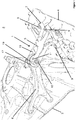
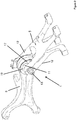
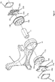
- the handling strut 1 of the invention is installed in an automobile 2 between a structural member 3 of the automobile, in this case a panel of the engine bay and the powertrain 4, in this case the engine.
- the handling strut 1 is formed of two main components, a first strut member 5, which, in use, is connected to the powertrain 4 and a second strut member 6, which is connected to the structural member 3 of the automobile.
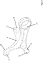
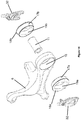
- the first strut member 5 that is connected to the powertrain 4 and shown in isolation in figure 3 is, in the embodiment, formed from a strong and rigid material, e.g. cast from metal, such as aluminium/steel.
- the first strut member 5 includes fixtures 7 in the form of feet provided with apertures 8 for rigid attachment to the powertrain 4 by way of bolts 9.
- the first strut member 5 is generally elongate and at the opposite end to the feet fixtures 7, a clevis 10 is provided.
- a shaft in the form of a sleeve 11 extends between the prolongations 12, which form the clevis 10.
- the sleeve 11 is held in fixed position place between the prolongations 12 of the clevis 10, by a fastener in the form of a nut (not shown) and bolt 13.
- the first strut member 5 is arranged such that the sleeve 11 extends in the longitudinal (fore and aft) direction of the automobile.
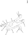
- the second strut member 6, shown in isolation in figure 4 similarly to the first strut member 5, is provided with fixtures, in this case three apertures 14 in fingers 15, which are arranged to be rigidly attached to different parts of the structural member 3 of the automobile so as to provide a firm and stable connection to the structural member 3.
- the second strut member 6 is elongate and at the opposite end to the fingers 15, a mounting point in the form of a cylindrical opening 16 is provided.
- the axis of the cylindrical opening 16 is arranged to extend in the longitudinal (fore and aft) direction of the automobile.
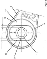
- the second strut member 6 is also formed of a strong and rigid material, e.g. cast from aluminium or steel. Mounted in the cylindrical opening, as shown in figures 1 and 2 , is a resilient, elastomeric bushing 17. The mounting point 16 of the second strut member 6 is slotted into the clevis 10, with the bushing 17 and the sleeve 11 having the same axis.
- the bushing 17 is provided as two halves, 17a 17b, these halves are pushed into the mounting point 16 from opposite sides and each have a flange 18a, 18b which locates in a circumferential recess in the mounting point 16.
- the bushing 17 i.e. each half thereof
- the bushing 17 is provided with an elongate aperture 19 (19a, 19b) which is larger than the outer diameter of the sleeve 11.
- the aperture 19 is generally rectangular (with rounded corners), and is oriented with its long axis substantially vertically.
- the air gap between the sleeve 11 and the top and bottom surfaces of the aperture is larger than that between the lateral surfaces of the aperture.
- a gap of 3.5mm (+/- 1mm) may be provided between each lateral wall and the closest surface of the sleeve 11 and a gap of 12mm (+/- 1mm) may be provided between each of the upper and lower surfaces of the aperture and the respective closest surface of the sleeve 11.
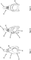
- a shaft location tool 22 is provided.
- the shaft location tool 22 consists of a pair of assembly clips 22a, 22b, each formed with an aperture engagement portion 23a, 23b, which is a protrusion shaped to mate with the sides of the aperture 19, being as wide and long as the aperture 19, arranged to engage with opposite sides of the aperture.
- the assembly clips 22a, 22b are each also provided with a pair of shaft-receiving claws 24a, 24b arranged to receive and clip onto the shaft 11.
- the claws 24 are resilient and may include comprise a pair of notches (one on each claw) arranged to receive the shaft 11.
- a band or strap (which may or may not be resiliently stretchable) such as a cable tie 26 may be provided to hold the sleeve 11 in the U-shaped region between the claws, and grooves 25 provided on each claw 24, into which the cable ties slot.
- the powertrain 4 is first installed in the automobile on mounts (not shown).
- the bushing 17 is inserted into the mounting point 16 of the second structural member, the sleeve 11 is inserted through the aperture 19 in the bushing 17 and the shaft location tool 22 is inserted into the aperture 19 of the bushing 17, such that the aperture engagement portions 23 engage with the aperture to locate the shaft location tool 22 in a fixed position in the aperture.
- the shaft is then pushed into the U-shaped region between the claws 24 of the shaft location tool 22 and cable ties 26 (where employed) are attached to hold the shaft in position in the u-shaped region, whereby it is centralised with respect to the aperture 19 in the bushing 17.
- the mounting point 16 is then slotted into the clevis 10 of the first strut member 5, and the bolt 13 introduced through holes 27 in the clevis, through the sleeve 11 and into a nut (not shown), which is tightened so as to fix the position of the sleeve 11 in the first strut member 5.
- the fixtures 14 in the second strut member and the fixtures 7 in the first strut member are then rigidly fastened in place to the structural member 3 and the powertrain 4 respectively.
- FIGS 7 to 9 show an alternative shaft location tool, and figure 10 shows that tool in use. Similar to the assembly tool shown in figure 5 this tool also comprises a pair of assembly clips 27. As the clips are identical, only one is illustrated in figures 7 to 9 . Similar to the assembly tool shown in figure 5 the clip comprises a body with a pair of shaft receiving claws 28 defining an open ended U-shaped slot. The claws support an aperture engagement portion 29 sized and shaped to mate with the sides of the aperture 19 in the bushing 17.
- the inside edges of the opposed claws 28 comprise opposed concave surfaces 30 which are extended by protrusions 31 which extend from the opposite side of the clip to the engagement portion.
- the opposed concave surfaces are shaped to conform to the outside surface of the sleeve 11.
- the clip is formed from a resiliently flexible material. It may, for example, be moulded from a resiliently flexible plastics material.
- the assembly tool is used in a similar fashion to that shown in figure 5 , as best understood from figure 10 .
- the sleeve 11 is introduced between the claws 28 of the clips it is received between the two opposed concave surfaces of, and gripped by, the claws which holds the sleeve in the necessary central position within the bushing 17. Then, when all the fixtures are tight the two clips are withdrawn by pulling them off the sleeve.
- the rings of each clip project above the part of the second strut member 6 defining the opening 16, enabling a user easily pull the clips from the assembly, for example by inserting a digit through the rings defined by the clips.
- FIGs 11 to 13 show yet another embodiment of a shaft location tool, and figure 14 shows that tool in use.
- this tool comprises a pair of assembly clips 32, only one of which is illustrated in figures 11 to 13 .
- Each clip comprises two pivotally connected parts.
- the first part 33 comprises a pair of shaft receiving claws which define an open ended U-shaped slot.
- the claws support an aperture engagement portion 34 sized and shaped to mate with the sides of the aperture 19 in the bushing 17.
- the inside edges of the opposed claws are substantially flat.
- the first part 33 of the clip is pivotally connected to the second part 35 of the clip.
- the second part comprises an arm 36 with a generally arcuate inside surface, and takes the general form of a hook.
- the first 33 and second 35 parts of the clip may be pivoted relative to one another between an open position, where the second part is away from the open ended slot of the first part and a closed positon, as shown in the drawings, where the arm 36 of the second part extends between the two claws defining the open ended slot.
- the second part 33 extends beyond the pivotal connection with the first part forming a graspable tab 37.
- Both parts of the clip are substantially rigid and may, for example, be moulded from a generally rigid plastic material, or machined from a metal, such as aluminium.
- clips are introduced into the aperture 19 in the bushing 17.
- the sleeve is introduced into the open ended slot defined by the first part 33 of the clip and, if it is not already in the closed state, the second part 35 of the clip is pivoted to bring the clip into the closed state so that the arm 36 of the second part retains the sleeve 11 in the open ended slot of the first part 33.
Landscapes
- Engineering & Computer Science (AREA)
- Mechanical Engineering (AREA)
- General Engineering & Computer Science (AREA)
- Chemical & Material Sciences (AREA)
- Combustion & Propulsion (AREA)
- Transportation (AREA)
- Health & Medical Sciences (AREA)
- Child & Adolescent Psychology (AREA)
- Arrangement Or Mounting Of Propulsion Units For Vehicles (AREA)
- Body Structure For Vehicles (AREA)
- Vibration Prevention Devices (AREA)
- Clamps And Clips (AREA)
Applications Claiming Priority (2)
| Application Number | Priority Date | Filing Date | Title |
|---|---|---|---|
| GB1516078.1A GB2537436B (en) | 2015-09-10 | 2015-09-10 | Handling strut |
| PCT/GB2016/052748 WO2017042552A1 (en) | 2015-09-10 | 2016-09-07 | Handling strut |
Publications (2)
| Publication Number | Publication Date |
|---|---|
| EP3347223A1 EP3347223A1 (en) | 2018-07-18 |
| EP3347223B1 true EP3347223B1 (en) | 2021-08-11 |
Family
ID=54362996
Family Applications (1)
| Application Number | Title | Priority Date | Filing Date |
|---|---|---|---|
| EP16770295.0A Active EP3347223B1 (en) | 2015-09-10 | 2016-09-07 | Handling strut |
Country Status (6)
| Country | Link |
|---|---|
| US (1) | US10363805B2 (enExample) |
| EP (1) | EP3347223B1 (enExample) |
| JP (1) | JP6905514B2 (enExample) |
| CN (1) | CN108473041B (enExample) |
| GB (2) | GB2537436B (enExample) |
| WO (1) | WO2017042552A1 (enExample) |
Families Citing this family (3)
| Publication number | Priority date | Publication date | Assignee | Title |
|---|---|---|---|---|
| FR3068649B1 (fr) * | 2017-07-10 | 2021-11-26 | Renault Sas | Dispositif monobloc de support d'un groupe motopropulseur integrant un palier relais |
| EP3914465A4 (en) * | 2019-01-25 | 2022-12-07 | Piaggio&C. S.p.A. | POWER TRAIN MOUNTING ARRANGEMENT |
| CN111922976B (zh) * | 2020-08-27 | 2022-09-06 | 广东电网有限责任公司 | 将军帽与套管密封面之间的软木橡胶垫分离工具 |
Family Cites Families (26)
| Publication number | Priority date | Publication date | Assignee | Title |
|---|---|---|---|---|
| US2824605A (en) * | 1955-01-12 | 1958-02-25 | Configured Tube Products Compa | Fuel-air mixing tube for gas burners |
| JPS602541B2 (ja) * | 1980-04-21 | 1985-01-22 | 日産自動車株式会社 | 防振装置 |
| US4518058A (en) * | 1981-12-21 | 1985-05-21 | Moog Automotive, Inc. | Engine torgue resisting strut and vibration damper |
| US4706946A (en) * | 1985-11-25 | 1987-11-17 | Thorn Richard P | Motion control strut |
| US4953278A (en) * | 1987-08-07 | 1990-09-04 | Shim-A-Line, Inc. | Method for adjusting alignment of a wheel |
| SE466996B (sv) * | 1987-12-03 | 1992-05-11 | Volvo Ab | Anordning foer upphaengning av en motor i ett fordon |
| DE4118266C2 (de) * | 1990-06-13 | 2000-11-02 | Volkswagen Ag | Allradantrieb |
| DE10018058B4 (de) * | 2000-04-12 | 2017-12-28 | Volkswagen Ag | Montagehilfe für ein Federbein |
| JP2004523707A (ja) * | 2001-03-06 | 2004-08-05 | ザ ティムケン カンパニー | 自動車両用ハブ/軸受アセンブリの取付け方法 |
| DE10117587A1 (de) * | 2001-04-07 | 2002-10-10 | Volkswagen Ag | Pendelstütze für ein Aggregat in einem Kraftfahrzeug |
| FR2824605B1 (fr) * | 2001-05-10 | 2006-02-10 | Peugeot Citroen Automobiles Sa | Attache de pre-maintien d'un premier element sur un second element afin de permettre sa fixation |
| JP2005315315A (ja) * | 2004-04-28 | 2005-11-10 | Tokai Rubber Ind Ltd | トルクロッド |
| KR200368305Y1 (ko) | 2004-06-30 | 2004-11-18 | 임봉규 | 스트럿 바 자동차 엔진 텐션 쇽업 쇼바 |
| JP4827607B2 (ja) * | 2006-05-18 | 2011-11-30 | 倉敷化工株式会社 | 防振リンクの取付構造 |
| GB201004473D0 (en) | 2010-03-17 | 2010-05-05 | Trysome Ltd | Lightweight engine mounting |
| US8342285B2 (en) * | 2010-10-14 | 2013-01-01 | GM Global Technology Operations LLC | Fully decoupled hydraulic torque strut |
| US8955230B2 (en) * | 2012-06-12 | 2015-02-17 | Solar Turbines Inc. | Shaft alignment tools and methods |
| JP6113501B2 (ja) * | 2012-12-28 | 2017-04-12 | 東洋ゴム工業株式会社 | 防振連結ロッド |
| JP6135205B2 (ja) * | 2013-03-11 | 2017-05-31 | 三菱自動車工業株式会社 | ロールロッド |
| JP5815602B2 (ja) * | 2013-06-17 | 2015-11-17 | 住友理工株式会社 | エンジンマウントおよびパワーユニットの防振支持構造 |
| US9242542B2 (en) * | 2013-07-04 | 2016-01-26 | Ford Global Technologies, Llc | System for reducing engine roll |
| DE102013213078A1 (de) * | 2013-07-04 | 2015-01-08 | Ford Global Technologies, Llc | Drehmomentstütze für eine Antriebsmaschine in einer Fahrzeugstruktur sowie Lager für eine Drehmomentstütze |
| DE112014004860T5 (de) * | 2013-10-24 | 2016-07-07 | Toyota Jidosha Kabushiki Kaisha | Fahrzeug mit Kraftmaschinenlagerungseinheiten |
| JP6123942B2 (ja) * | 2014-02-28 | 2017-05-10 | 日産自動車株式会社 | 4輪駆動車のクラッチ制御装置 |
| CN103895489A (zh) | 2014-03-28 | 2014-07-02 | 山东美晨科技股份有限公司 | 一种新型发动机支撑 |
| US10018058B2 (en) * | 2015-07-14 | 2018-07-10 | The Boeing Company | Laterally reinforced variable pitch rotor |
-
2015
- 2015-09-10 GB GB1516078.1A patent/GB2537436B/en active Active
-
2016
- 2016-09-07 US US15/759,068 patent/US10363805B2/en active Active
- 2016-09-07 EP EP16770295.0A patent/EP3347223B1/en active Active
- 2016-09-07 JP JP2018513379A patent/JP6905514B2/ja active Active
- 2016-09-07 WO PCT/GB2016/052748 patent/WO2017042552A1/en not_active Ceased
- 2016-09-07 CN CN201680052599.0A patent/CN108473041B/zh active Active
- 2016-09-07 GB GB1615168.0A patent/GB2543635B/en active Active
Non-Patent Citations (1)
| Title |
|---|
| None * |
Also Published As
| Publication number | Publication date |
|---|---|
| GB2537436A (en) | 2016-10-19 |
| JP2018530466A (ja) | 2018-10-18 |
| CN108473041A (zh) | 2018-08-31 |
| EP3347223A1 (en) | 2018-07-18 |
| WO2017042552A1 (en) | 2017-03-16 |
| US20190047396A1 (en) | 2019-02-14 |
| GB2543635B (en) | 2020-08-26 |
| GB201516078D0 (en) | 2015-10-28 |
| CN108473041B (zh) | 2022-01-28 |
| GB201615168D0 (en) | 2016-10-19 |
| GB2537436B (en) | 2017-04-19 |
| GB2543635A (en) | 2017-04-26 |
| US10363805B2 (en) | 2019-07-30 |
| JP6905514B2 (ja) | 2021-07-21 |
Similar Documents
| Publication | Publication Date | Title |
|---|---|---|
| US6513801B1 (en) | Hinged/split reinforced clam shell bushing | |
| US4623164A (en) | Band clamp for axle assembly and the like | |
| US8800703B2 (en) | Hood mount assembly | |
| EP3347223B1 (en) | Handling strut | |
| US10173560B2 (en) | Isolation system for a seat | |
| KR100405359B1 (ko) | 자동차용 엔진마운트 | |
| US20190389513A1 (en) | Bracket and mounting system for use in supporting a module within a vehicle | |
| CN110356215B (zh) | 驱动源的支承构造 | |
| US11118647B2 (en) | Vibration damper | |
| KR20130100364A (ko) | 소켓 마운트 구조를 갖는 분리체 | |
| WO2017019584A1 (en) | Split bushing torque strut isolator assembly | |
| CN109760503B (zh) | 动力总成抗扭拉杆结构 | |
| CN112659877A (zh) | 用于车辆的动力总成的安装系统 | |
| GB2534240A (en) | Bushing, in particular for a vehicle | |
| KR101596709B1 (ko) | 관성 2점 지지 방식의 엔진마운팅 구조 | |
| JP3767396B2 (ja) | エンジンマウントおよびそれを用いた自動車用パワーユニット支持機構 | |
| KR101705148B1 (ko) | 차량용 서브프레임의 구조 | |
| CN218316120U (zh) | 一种车用悬架控制臂总成结构 | |
| KR102237071B1 (ko) | 서브프레임 부시 | |
| EP4206488A1 (en) | Vibration isolation support device | |
| CA2844358C (en) | Hood mount assembly | |
| CN215720480U (zh) | 衬套及车辆 | |
| JP7460572B2 (ja) | 防振装置 | |
| JP2020159449A (ja) | 筒型防振装置用ブラケット | |
| US9347518B1 (en) | Vibration-isolating bracket assembly |
Legal Events
| Date | Code | Title | Description |
|---|---|---|---|
| STAA | Information on the status of an ep patent application or granted ep patent |
Free format text: STATUS: THE INTERNATIONAL PUBLICATION HAS BEEN MADE |
|
| PUAI | Public reference made under article 153(3) epc to a published international application that has entered the european phase |
Free format text: ORIGINAL CODE: 0009012 |
|
| STAA | Information on the status of an ep patent application or granted ep patent |
Free format text: STATUS: REQUEST FOR EXAMINATION WAS MADE |
|
| 17P | Request for examination filed |
Effective date: 20180220 |
|
| AK | Designated contracting states |
Kind code of ref document: A1 Designated state(s): AL AT BE BG CH CY CZ DE DK EE ES FI FR GB GR HR HU IE IS IT LI LT LU LV MC MK MT NL NO PL PT RO RS SE SI SK SM TR |
|
| AX | Request for extension of the european patent |
Extension state: BA ME |
|
| DAV | Request for validation of the european patent (deleted) | ||
| DAX | Request for extension of the european patent (deleted) | ||
| STAA | Information on the status of an ep patent application or granted ep patent |
Free format text: STATUS: EXAMINATION IS IN PROGRESS |
|
| 17Q | First examination report despatched |
Effective date: 20200703 |
|
| GRAP | Despatch of communication of intention to grant a patent |
Free format text: ORIGINAL CODE: EPIDOSNIGR1 |
|
| STAA | Information on the status of an ep patent application or granted ep patent |
Free format text: STATUS: GRANT OF PATENT IS INTENDED |
|
| INTG | Intention to grant announced |
Effective date: 20210303 |
|
| GRAS | Grant fee paid |
Free format text: ORIGINAL CODE: EPIDOSNIGR3 |
|
| GRAA | (expected) grant |
Free format text: ORIGINAL CODE: 0009210 |
|
| STAA | Information on the status of an ep patent application or granted ep patent |
Free format text: STATUS: THE PATENT HAS BEEN GRANTED |
|
| AK | Designated contracting states |
Kind code of ref document: B1 Designated state(s): AL AT BE BG CH CY CZ DE DK EE ES FI FR GB GR HR HU IE IS IT LI LT LU LV MC MK MT NL NO PL PT RO RS SE SI SK SM TR |
|
| REG | Reference to a national code |
Ref country code: CH Ref legal event code: EP |
|
| REG | Reference to a national code |
Ref country code: DE Ref legal event code: R096 Ref document number: 602016062042 Country of ref document: DE |
|
| REG | Reference to a national code |
Ref country code: IE Ref legal event code: FG4D Ref country code: AT Ref legal event code: REF Ref document number: 1419038 Country of ref document: AT Kind code of ref document: T Effective date: 20210915 |
|
| REG | Reference to a national code |
Ref country code: LT Ref legal event code: MG9D |
|
| REG | Reference to a national code |
Ref country code: NL Ref legal event code: MP Effective date: 20210811 |
|
| REG | Reference to a national code |
Ref country code: AT Ref legal event code: MK05 Ref document number: 1419038 Country of ref document: AT Kind code of ref document: T Effective date: 20210811 |
|
| PG25 | Lapsed in a contracting state [announced via postgrant information from national office to epo] |
Ref country code: RS Free format text: LAPSE BECAUSE OF FAILURE TO SUBMIT A TRANSLATION OF THE DESCRIPTION OR TO PAY THE FEE WITHIN THE PRESCRIBED TIME-LIMIT Effective date: 20210811 Ref country code: SE Free format text: LAPSE BECAUSE OF FAILURE TO SUBMIT A TRANSLATION OF THE DESCRIPTION OR TO PAY THE FEE WITHIN THE PRESCRIBED TIME-LIMIT Effective date: 20210811 Ref country code: FI Free format text: LAPSE BECAUSE OF FAILURE TO SUBMIT A TRANSLATION OF THE DESCRIPTION OR TO PAY THE FEE WITHIN THE PRESCRIBED TIME-LIMIT Effective date: 20210811 Ref country code: ES Free format text: LAPSE BECAUSE OF FAILURE TO SUBMIT A TRANSLATION OF THE DESCRIPTION OR TO PAY THE FEE WITHIN THE PRESCRIBED TIME-LIMIT Effective date: 20210811 Ref country code: HR Free format text: LAPSE BECAUSE OF FAILURE TO SUBMIT A TRANSLATION OF THE DESCRIPTION OR TO PAY THE FEE WITHIN THE PRESCRIBED TIME-LIMIT Effective date: 20210811 Ref country code: NO Free format text: LAPSE BECAUSE OF FAILURE TO SUBMIT A TRANSLATION OF THE DESCRIPTION OR TO PAY THE FEE WITHIN THE PRESCRIBED TIME-LIMIT Effective date: 20211111 Ref country code: PT Free format text: LAPSE BECAUSE OF FAILURE TO SUBMIT A TRANSLATION OF THE DESCRIPTION OR TO PAY THE FEE WITHIN THE PRESCRIBED TIME-LIMIT Effective date: 20211213 Ref country code: LT Free format text: LAPSE BECAUSE OF FAILURE TO SUBMIT A TRANSLATION OF THE DESCRIPTION OR TO PAY THE FEE WITHIN THE PRESCRIBED TIME-LIMIT Effective date: 20210811 Ref country code: BG Free format text: LAPSE BECAUSE OF FAILURE TO SUBMIT A TRANSLATION OF THE DESCRIPTION OR TO PAY THE FEE WITHIN THE PRESCRIBED TIME-LIMIT Effective date: 20211111 Ref country code: AT Free format text: LAPSE BECAUSE OF FAILURE TO SUBMIT A TRANSLATION OF THE DESCRIPTION OR TO PAY THE FEE WITHIN THE PRESCRIBED TIME-LIMIT Effective date: 20210811 |
|
| PG25 | Lapsed in a contracting state [announced via postgrant information from national office to epo] |
Ref country code: PL Free format text: LAPSE BECAUSE OF FAILURE TO SUBMIT A TRANSLATION OF THE DESCRIPTION OR TO PAY THE FEE WITHIN THE PRESCRIBED TIME-LIMIT Effective date: 20210811 Ref country code: LV Free format text: LAPSE BECAUSE OF FAILURE TO SUBMIT A TRANSLATION OF THE DESCRIPTION OR TO PAY THE FEE WITHIN THE PRESCRIBED TIME-LIMIT Effective date: 20210811 Ref country code: GR Free format text: LAPSE BECAUSE OF FAILURE TO SUBMIT A TRANSLATION OF THE DESCRIPTION OR TO PAY THE FEE WITHIN THE PRESCRIBED TIME-LIMIT Effective date: 20211112 |
|
| PG25 | Lapsed in a contracting state [announced via postgrant information from national office to epo] |
Ref country code: NL Free format text: LAPSE BECAUSE OF FAILURE TO SUBMIT A TRANSLATION OF THE DESCRIPTION OR TO PAY THE FEE WITHIN THE PRESCRIBED TIME-LIMIT Effective date: 20210811 |
|
| PG25 | Lapsed in a contracting state [announced via postgrant information from national office to epo] |
Ref country code: DK Free format text: LAPSE BECAUSE OF FAILURE TO SUBMIT A TRANSLATION OF THE DESCRIPTION OR TO PAY THE FEE WITHIN THE PRESCRIBED TIME-LIMIT Effective date: 20210811 |
|
| REG | Reference to a national code |
Ref country code: DE Ref legal event code: R097 Ref document number: 602016062042 Country of ref document: DE |
|
| REG | Reference to a national code |
Ref country code: CH Ref legal event code: PL |
|
| REG | Reference to a national code |
Ref country code: BE Ref legal event code: MM Effective date: 20210930 |
|
| PG25 | Lapsed in a contracting state [announced via postgrant information from national office to epo] |
Ref country code: SM Free format text: LAPSE BECAUSE OF FAILURE TO SUBMIT A TRANSLATION OF THE DESCRIPTION OR TO PAY THE FEE WITHIN THE PRESCRIBED TIME-LIMIT Effective date: 20210811 Ref country code: SK Free format text: LAPSE BECAUSE OF FAILURE TO SUBMIT A TRANSLATION OF THE DESCRIPTION OR TO PAY THE FEE WITHIN THE PRESCRIBED TIME-LIMIT Effective date: 20210811 Ref country code: RO Free format text: LAPSE BECAUSE OF FAILURE TO SUBMIT A TRANSLATION OF THE DESCRIPTION OR TO PAY THE FEE WITHIN THE PRESCRIBED TIME-LIMIT Effective date: 20210811 Ref country code: MC Free format text: LAPSE BECAUSE OF FAILURE TO SUBMIT A TRANSLATION OF THE DESCRIPTION OR TO PAY THE FEE WITHIN THE PRESCRIBED TIME-LIMIT Effective date: 20210811 Ref country code: EE Free format text: LAPSE BECAUSE OF FAILURE TO SUBMIT A TRANSLATION OF THE DESCRIPTION OR TO PAY THE FEE WITHIN THE PRESCRIBED TIME-LIMIT Effective date: 20210811 Ref country code: CZ Free format text: LAPSE BECAUSE OF FAILURE TO SUBMIT A TRANSLATION OF THE DESCRIPTION OR TO PAY THE FEE WITHIN THE PRESCRIBED TIME-LIMIT Effective date: 20210811 Ref country code: AL Free format text: LAPSE BECAUSE OF FAILURE TO SUBMIT A TRANSLATION OF THE DESCRIPTION OR TO PAY THE FEE WITHIN THE PRESCRIBED TIME-LIMIT Effective date: 20210811 |
|
| PLBE | No opposition filed within time limit |
Free format text: ORIGINAL CODE: 0009261 |
|
| STAA | Information on the status of an ep patent application or granted ep patent |
Free format text: STATUS: NO OPPOSITION FILED WITHIN TIME LIMIT |
|
| 26N | No opposition filed |
Effective date: 20220512 |
|
| PG25 | Lapsed in a contracting state [announced via postgrant information from national office to epo] |
Ref country code: LU Free format text: LAPSE BECAUSE OF NON-PAYMENT OF DUE FEES Effective date: 20210907 Ref country code: IT Free format text: LAPSE BECAUSE OF FAILURE TO SUBMIT A TRANSLATION OF THE DESCRIPTION OR TO PAY THE FEE WITHIN THE PRESCRIBED TIME-LIMIT Effective date: 20210811 Ref country code: IE Free format text: LAPSE BECAUSE OF NON-PAYMENT OF DUE FEES Effective date: 20210907 Ref country code: BE Free format text: LAPSE BECAUSE OF NON-PAYMENT OF DUE FEES Effective date: 20210930 |
|
| PG25 | Lapsed in a contracting state [announced via postgrant information from national office to epo] |
Ref country code: SI Free format text: LAPSE BECAUSE OF FAILURE TO SUBMIT A TRANSLATION OF THE DESCRIPTION OR TO PAY THE FEE WITHIN THE PRESCRIBED TIME-LIMIT Effective date: 20210811 Ref country code: LI Free format text: LAPSE BECAUSE OF NON-PAYMENT OF DUE FEES Effective date: 20210930 Ref country code: CH Free format text: LAPSE BECAUSE OF NON-PAYMENT OF DUE FEES Effective date: 20210930 |
|
| PG25 | Lapsed in a contracting state [announced via postgrant information from national office to epo] |
Ref country code: HU Free format text: LAPSE BECAUSE OF FAILURE TO SUBMIT A TRANSLATION OF THE DESCRIPTION OR TO PAY THE FEE WITHIN THE PRESCRIBED TIME-LIMIT; INVALID AB INITIO Effective date: 20160907 |
|
| P01 | Opt-out of the competence of the unified patent court (upc) registered |
Effective date: 20230420 |
|
| PG25 | Lapsed in a contracting state [announced via postgrant information from national office to epo] |
Ref country code: CY Free format text: LAPSE BECAUSE OF FAILURE TO SUBMIT A TRANSLATION OF THE DESCRIPTION OR TO PAY THE FEE WITHIN THE PRESCRIBED TIME-LIMIT Effective date: 20210811 |
|
| PGFP | Annual fee paid to national office [announced via postgrant information from national office to epo] |
Ref country code: FR Payment date: 20230811 Year of fee payment: 8 |
|
| PG25 | Lapsed in a contracting state [announced via postgrant information from national office to epo] |
Ref country code: MK Free format text: LAPSE BECAUSE OF FAILURE TO SUBMIT A TRANSLATION OF THE DESCRIPTION OR TO PAY THE FEE WITHIN THE PRESCRIBED TIME-LIMIT Effective date: 20210811 |
|
| PG25 | Lapsed in a contracting state [announced via postgrant information from national office to epo] |
Ref country code: TR Free format text: LAPSE BECAUSE OF FAILURE TO SUBMIT A TRANSLATION OF THE DESCRIPTION OR TO PAY THE FEE WITHIN THE PRESCRIBED TIME-LIMIT Effective date: 20210811 |
|
| PG25 | Lapsed in a contracting state [announced via postgrant information from national office to epo] |
Ref country code: MT Free format text: LAPSE BECAUSE OF FAILURE TO SUBMIT A TRANSLATION OF THE DESCRIPTION OR TO PAY THE FEE WITHIN THE PRESCRIBED TIME-LIMIT Effective date: 20210811 |
|
| PGFP | Annual fee paid to national office [announced via postgrant information from national office to epo] |
Ref country code: DE Payment date: 20240930 Year of fee payment: 9 |
|
| PG25 | Lapsed in a contracting state [announced via postgrant information from national office to epo] |
Ref country code: FR Free format text: LAPSE BECAUSE OF NON-PAYMENT OF DUE FEES Effective date: 20240930 |
|
| PGFP | Annual fee paid to national office [announced via postgrant information from national office to epo] |
Ref country code: GB Payment date: 20250903 Year of fee payment: 10 |