EP3346239B1 - Positionssensor - Google Patents
Positionssensor Download PDFInfo
- Publication number
- EP3346239B1 EP3346239B1 EP16841350.8A EP16841350A EP3346239B1 EP 3346239 B1 EP3346239 B1 EP 3346239B1 EP 16841350 A EP16841350 A EP 16841350A EP 3346239 B1 EP3346239 B1 EP 3346239B1
- Authority
- EP
- European Patent Office
- Prior art keywords
- movable object
- fixing portion
- magnet
- position sensor
- contact
- Prior art date
- Legal status (The legal status is an assumption and is not a legal conclusion. Google has not performed a legal analysis and makes no representation as to the accuracy of the status listed.)
- Active
Links
Images


















Classifications
-
- G—PHYSICS
- G01—MEASURING; TESTING
- G01D—MEASURING NOT SPECIALLY ADAPTED FOR A SPECIFIC VARIABLE; ARRANGEMENTS FOR MEASURING TWO OR MORE VARIABLES NOT COVERED IN A SINGLE OTHER SUBCLASS; TARIFF METERING APPARATUS; MEASURING OR TESTING NOT OTHERWISE PROVIDED FOR
- G01D5/00—Mechanical means for transferring the output of a sensing member; Means for converting the output of a sensing member to another variable where the form or nature of the sensing member does not constrain the means for converting; Transducers not specially adapted for a specific variable
- G01D5/12—Mechanical means for transferring the output of a sensing member; Means for converting the output of a sensing member to another variable where the form or nature of the sensing member does not constrain the means for converting; Transducers not specially adapted for a specific variable using electric or magnetic means
- G01D5/14—Mechanical means for transferring the output of a sensing member; Means for converting the output of a sensing member to another variable where the form or nature of the sensing member does not constrain the means for converting; Transducers not specially adapted for a specific variable using electric or magnetic means influencing the magnitude of a current or voltage
- G01D5/142—Mechanical means for transferring the output of a sensing member; Means for converting the output of a sensing member to another variable where the form or nature of the sensing member does not constrain the means for converting; Transducers not specially adapted for a specific variable using electric or magnetic means influencing the magnitude of a current or voltage using Hall-effect devices
- G01D5/145—Mechanical means for transferring the output of a sensing member; Means for converting the output of a sensing member to another variable where the form or nature of the sensing member does not constrain the means for converting; Transducers not specially adapted for a specific variable using electric or magnetic means influencing the magnitude of a current or voltage using Hall-effect devices influenced by the relative movement between the Hall device and magnetic fields
-
- F—MECHANICAL ENGINEERING; LIGHTING; HEATING; WEAPONS; BLASTING
- F16—ENGINEERING ELEMENTS AND UNITS; GENERAL MEASURES FOR PRODUCING AND MAINTAINING EFFECTIVE FUNCTIONING OF MACHINES OR INSTALLATIONS; THERMAL INSULATION IN GENERAL
- F16B—DEVICES FOR FASTENING OR SECURING CONSTRUCTIONAL ELEMENTS OR MACHINE PARTS TOGETHER, e.g. NAILS, BOLTS, CIRCLIPS, CLAMPS, CLIPS OR WEDGES; JOINTS OR JOINTING
- F16B2/00—Friction-grip releasable fastenings
- F16B2/20—Clips, i.e. with gripping action effected solely by the inherent resistance to deformation of the material of the fastening
- F16B2/22—Clips, i.e. with gripping action effected solely by the inherent resistance to deformation of the material of the fastening of resilient material, e.g. rubbery material
-
- F—MECHANICAL ENGINEERING; LIGHTING; HEATING; WEAPONS; BLASTING
- F16—ENGINEERING ELEMENTS AND UNITS; GENERAL MEASURES FOR PRODUCING AND MAINTAINING EFFECTIVE FUNCTIONING OF MACHINES OR INSTALLATIONS; THERMAL INSULATION IN GENERAL
- F16B—DEVICES FOR FASTENING OR SECURING CONSTRUCTIONAL ELEMENTS OR MACHINE PARTS TOGETHER, e.g. NAILS, BOLTS, CIRCLIPS, CLAMPS, CLIPS OR WEDGES; JOINTS OR JOINTING
- F16B21/00—Means for preventing relative axial movement of a pin, spigot, shaft or the like and a member surrounding it; Stud-and-socket releasable fastenings
- F16B21/10—Means for preventing relative axial movement of a pin, spigot, shaft or the like and a member surrounding it; Stud-and-socket releasable fastenings by separate parts
- F16B21/16—Means for preventing relative axial movement of a pin, spigot, shaft or the like and a member surrounding it; Stud-and-socket releasable fastenings by separate parts with grooves or notches in the pin or shaft
- F16B21/18—Means for preventing relative axial movement of a pin, spigot, shaft or the like and a member surrounding it; Stud-and-socket releasable fastenings by separate parts with grooves or notches in the pin or shaft with circlips or like resilient retaining devices, i.e. resilient in the plane of the ring or the like; Details
-
- F—MECHANICAL ENGINEERING; LIGHTING; HEATING; WEAPONS; BLASTING
- F16—ENGINEERING ELEMENTS AND UNITS; GENERAL MEASURES FOR PRODUCING AND MAINTAINING EFFECTIVE FUNCTIONING OF MACHINES OR INSTALLATIONS; THERMAL INSULATION IN GENERAL
- F16B—DEVICES FOR FASTENING OR SECURING CONSTRUCTIONAL ELEMENTS OR MACHINE PARTS TOGETHER, e.g. NAILS, BOLTS, CIRCLIPS, CLAMPS, CLIPS OR WEDGES; JOINTS OR JOINTING
- F16B5/00—Joining sheets or plates, e.g. panels, to one another or to strips or bars parallel to them
- F16B5/06—Joining sheets or plates, e.g. panels, to one another or to strips or bars parallel to them by means of clamps or clips
- F16B5/0685—Joining sheets or plates to strips or bars
-
- G—PHYSICS
- G01—MEASURING; TESTING
- G01B—MEASURING LENGTH, THICKNESS OR SIMILAR LINEAR DIMENSIONS; MEASURING ANGLES; MEASURING AREAS; MEASURING IRREGULARITIES OF SURFACES OR CONTOURS
- G01B7/00—Measuring arrangements characterised by the use of electric or magnetic techniques
- G01B7/003—Measuring arrangements characterised by the use of electric or magnetic techniques for measuring position, not involving coordinate determination
-
- G—PHYSICS
- G01—MEASURING; TESTING
- G01D—MEASURING NOT SPECIALLY ADAPTED FOR A SPECIFIC VARIABLE; ARRANGEMENTS FOR MEASURING TWO OR MORE VARIABLES NOT COVERED IN A SINGLE OTHER SUBCLASS; TARIFF METERING APPARATUS; MEASURING OR TESTING NOT OTHERWISE PROVIDED FOR
- G01D11/00—Component parts of measuring arrangements not specially adapted for a specific variable
- G01D11/24—Housings ; Casings for instruments
- G01D11/245—Housings for sensors
-
- G—PHYSICS
- G01—MEASURING; TESTING
- G01D—MEASURING NOT SPECIALLY ADAPTED FOR A SPECIFIC VARIABLE; ARRANGEMENTS FOR MEASURING TWO OR MORE VARIABLES NOT COVERED IN A SINGLE OTHER SUBCLASS; TARIFF METERING APPARATUS; MEASURING OR TESTING NOT OTHERWISE PROVIDED FOR
- G01D5/00—Mechanical means for transferring the output of a sensing member; Means for converting the output of a sensing member to another variable where the form or nature of the sensing member does not constrain the means for converting; Transducers not specially adapted for a specific variable
- G01D5/12—Mechanical means for transferring the output of a sensing member; Means for converting the output of a sensing member to another variable where the form or nature of the sensing member does not constrain the means for converting; Transducers not specially adapted for a specific variable using electric or magnetic means
-
- G—PHYSICS
- G01—MEASURING; TESTING
- G01D—MEASURING NOT SPECIALLY ADAPTED FOR A SPECIFIC VARIABLE; ARRANGEMENTS FOR MEASURING TWO OR MORE VARIABLES NOT COVERED IN A SINGLE OTHER SUBCLASS; TARIFF METERING APPARATUS; MEASURING OR TESTING NOT OTHERWISE PROVIDED FOR
- G01D5/00—Mechanical means for transferring the output of a sensing member; Means for converting the output of a sensing member to another variable where the form or nature of the sensing member does not constrain the means for converting; Transducers not specially adapted for a specific variable
- G01D5/12—Mechanical means for transferring the output of a sensing member; Means for converting the output of a sensing member to another variable where the form or nature of the sensing member does not constrain the means for converting; Transducers not specially adapted for a specific variable using electric or magnetic means
- G01D5/14—Mechanical means for transferring the output of a sensing member; Means for converting the output of a sensing member to another variable where the form or nature of the sensing member does not constrain the means for converting; Transducers not specially adapted for a specific variable using electric or magnetic means influencing the magnitude of a current or voltage
-
- G—PHYSICS
- G01—MEASURING; TESTING
- G01D—MEASURING NOT SPECIALLY ADAPTED FOR A SPECIFIC VARIABLE; ARRANGEMENTS FOR MEASURING TWO OR MORE VARIABLES NOT COVERED IN A SINGLE OTHER SUBCLASS; TARIFF METERING APPARATUS; MEASURING OR TESTING NOT OTHERWISE PROVIDED FOR
- G01D5/00—Mechanical means for transferring the output of a sensing member; Means for converting the output of a sensing member to another variable where the form or nature of the sensing member does not constrain the means for converting; Transducers not specially adapted for a specific variable
- G01D5/12—Mechanical means for transferring the output of a sensing member; Means for converting the output of a sensing member to another variable where the form or nature of the sensing member does not constrain the means for converting; Transducers not specially adapted for a specific variable using electric or magnetic means
- G01D5/14—Mechanical means for transferring the output of a sensing member; Means for converting the output of a sensing member to another variable where the form or nature of the sensing member does not constrain the means for converting; Transducers not specially adapted for a specific variable using electric or magnetic means influencing the magnitude of a current or voltage
- G01D5/16—Mechanical means for transferring the output of a sensing member; Means for converting the output of a sensing member to another variable where the form or nature of the sensing member does not constrain the means for converting; Transducers not specially adapted for a specific variable using electric or magnetic means influencing the magnitude of a current or voltage by varying resistance
-
- F—MECHANICAL ENGINEERING; LIGHTING; HEATING; WEAPONS; BLASTING
- F16—ENGINEERING ELEMENTS AND UNITS; GENERAL MEASURES FOR PRODUCING AND MAINTAINING EFFECTIVE FUNCTIONING OF MACHINES OR INSTALLATIONS; THERMAL INSULATION IN GENERAL
- F16B—DEVICES FOR FASTENING OR SECURING CONSTRUCTIONAL ELEMENTS OR MACHINE PARTS TOGETHER, e.g. NAILS, BOLTS, CIRCLIPS, CLAMPS, CLIPS OR WEDGES; JOINTS OR JOINTING
- F16B2200/00—Constructional details of connections not covered for in other groups of this subclass
- F16B2200/83—Use of a magnetic material
Definitions
- the present invention relates to a position sensor.
- the magnet installation structure of PTL 1 has a magnet, a holder, and a shaft.
- the holder is formed in a partially truncated cylindrical shape.
- the shaft has a hollow, and the magnet is disposed in the hollow of the shaft, so that the magnet is easily fixed in an accurate position by fitting the holder perpendicularly to the axial direction of the shaft.
- the magnet may move perpendicularly to the axial direction of the shaft or in the axial direction of the shaft if a slight gap exists between the magnet and the holder. Therefore, a position between the shaft and the magnet may change disadvantageously.
- an object of the present invention is to provide a position sensor capable of improve installability for installing the magnet in a movable object in the axial direction, such as the shaft.
- a position sensor as defined in claim 1. It includes a magnetic sensor and a target installed in a movable object, wherein the target has a magnet and a magnet base that holds the magnet, and the magnet base has a magnet holding portion and a fixing portion for fixation to the movable object, the magnet holding portion and the fixing portion being formed integrally.
- the present invention it is possible to easily install the magnet in the movable object that moves in the axial direction, such as the shaft.
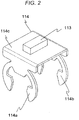
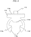
- FIGS. 1 to 4 A first embodiment according to the invention will be described with reference to FIGS. 1 to 4 .
- a position sensor has a target 110 installed on a movable object 112 moving in an axial direction and a magnetic sensor 111 for detecting a movement of the target 110.
- the movable object 112 will be described as a shaft by way of example .
- the magnetic sensor 111 includes, for example, a sensor using a Hall effect element or a sensor using a GMR element.
- the target 110 has a magnet 113 for generating a magnetic flux and a magnet base 114 for holding the magnet.
- the magnet base 114 has a structure in which a first fixing portion 114a, a second fixing portion 114b, and a magnet holding portion 114c are integrally formed.
- the first and second fixing portions 114a and 114b are arranged side by side along an axial direction (in other words, movement direction) of the movable object 112.
- the first and second fixing portions 114a and 114b are provided axially outward of an area where the magnet 113 of the magnet holding portion 114c is mounted.
- the first and second fixing portions 114a and 114b have a partially opened ring shape in order to allow installation perpendicular to the axial direction of the movable object 112.
- the first fixing portion is shaped to have first, second, and third contact portions 114d, 114e, and 114f coming into contact with the movable object 112.
- the first to third contact portions are formed such that centers of each contact portion coming into contact with the movable object 112 form an equilateral triangle.
- the first contact portion 114d is formed apart from the opening and has a flat portion.
- the second and third contact portions 114e and 114f are formed in the opening side of the first fixing portion 114a to match a circumferential shape (side shape) of the movable object 112. If the movable object 112 has a cylindrical shape, the circumferential shape is an arc shape.
- the first fixing portion 114a has a non-contact portion that does not come into contact with the movable object 112 between the first and second contact portions 114d and 114e. Similarly, a non-contact portion that does not come into contact with the movable object 112 is also provided between the first and third fixing portions 114d and 114f. In other words, the first fixing portion 114a has a region having a cross-sectional area smaller than that of each contact portion.
- first fixing portion 114a is tapered such that a shape of its opening 114g is gradually narrowed from the opening end toward the inside.
- the second fixing portion may have the same shape as that of the first fixing portion.
- the target 110 can be installed in the shaft serving as a movable object using the first and second fixing portions 114a and 114b integrated into the magnet holding portion 114c. For this reason, according to this embodiment, the target can be installed in the shaft serving as a sensing target without using a fastening part such as a screw.
- first and second fixing portions 114a and 114b are partially opened ring-shaped fixing portions. Therefore, they can be easily installed from the side direction of the movable object 112.
- the first fixing portion is shaped to fix the movable object in three portions including the first to third contact portions, it is possible to prevent a positional deviation in a rotational direction.
- the center points of each contact portion are formed in an equilateral triangle shape, a stress generated during installation becomes symmetric with respect to a center of the movable object 112 three times, so that a rotational stress is cancelled.
- one of the three contact portions apart from the opening is shaped to have a flat portion, and the opening side matches the circumferential shape of the shaft. For this reason, it is possible to improve insertion easiness (installability) to the shaft and more effectively suppress a positional deviation in the rotational direction using the flat portion.
- a diameter of the shaft may change when the shaft is inserted in the axial direction. In this case, it is difficult to promote insertion of the magnet base and adherence to the shaft.
- the magnet base can be inserted from the direction perpendicular to the shaft. Therefore, it is possible to secure adherence or installability between the shaft and the magnet base. Since the non-contact portion has a cross-sectional area smaller than that of the contact portion, it can be easily deformed. Therefore, it is possible to further improve installability at the time of insertion.
- the second and third installation portions are formed on an arc that matches the circumferential shape of the shaft, this change in the diameter can be absorbed by deformation of the non-contact portion even when the diameter of the shaft changes.
- the second and third fixing portions have an arc shape that matches the circumferential shape of the shaft, it is possible to secure adherence between the shaft and the contact portion even when the diameter changes.
- the opening 114g has a tapered shape, it is possible to prevent a point-to-surface contact in which the tip of the first fixing portion 114a comes into contact with the movable object 112.
- the first fixing portion 114a and the movable object 112 make a surface-to-surface contact, it is possible to disperse a stress applied when the target 110 is inserted into the movable object. Therefore, there is no need to insert the target 110 by applying a force more than necessary.
- first and second fixing portions in the same shape, it is possible to further improve installability.
- the same force is applied to the first and second fixing portions during and after the installation. Therefore, it is possible to prevent a rotational or distortional force from being applied to the target 110 and further improve installability and positional accuracy of the target 110 to the movable object 112.
- the second fixing portion 114b in a shape different from that of the first fixing portion 114a, it is possible to easily recognize the installation direction.
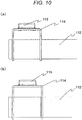
- FIGS. 5 to 10 A second embodiment of the present invention will be described with reference to FIGS. 5 to 10 . Note that like reference numerals denote like elements as in the first embodiment, and they will not be described repeatedly.
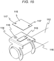
- a position sensor further has a base cover 115 for protecting the magnet 113.
- the base cover 115 is fixed to the magnet base 114 through welding or the like.
- the base cover 115 has a housing hollow for housing the magnet 113.
- a protrusion and a hollow for positioning are formed in the magnet base 114 and the base cover 115 as illustrated in the modification of FIGS. 8 to 10 , positioning is facilitated preferably.
- the positioning protrusion may be provided in the base cover 115, and the positioning hollow may be provided in the magnet base 114.
- the positioning hollow 117 may be provided in the base cover 115, and the positioning protrusion 116 may be provided in the magnet base.
- the magnet 113 is protected by the base cover 115. Therefore, it is possible to further improve reliability.
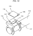
- FIGS. 11 to 16 A third embodiment of the present invention will be described with reference to FIGS. 11 to 16 . Note that like reference numerals denote like elements as in the first and second embodiments, and they will not be described repeatedly.
- the third embodiment of the present invention is different from the second embodiment in that the housing hollow for housing the magnet in the second embodiment is formed in the magnet base side.
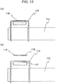
- the magnet 113 Since the magnet 113 is housed in the hollow provided in the magnet base 114, it is possible to hold the magnet 113 without increasing the height of the target 110. Therefore, it is possible to miniaturize the target 110 as a whole.
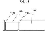
- the shaft 112 is provided with first and second grooves 112a and 112b along a circumferential direction.
- a truncated portion 112c formed by cutting a part of the side surface is provided on the area including the first and second grooves on the side surface of the shaft 112.
- the target 110 is fixed to the shaft 112 by fitting the first fixing portion 114a into the first groove 112a and fitting the second fixing portion 114b into the second groove 112b.
- first contact portion 114d of the first fixing portion 114a comes into contact with the truncated portion 112c provided in the shaft 112 (in other words, the flat portion).
- the first contact portion 114d comes into contact with the truncated portion 112c as in the first fixing portion 114a.
- first and second fixing portions 114a and 114b having a ring shape By fitting the first and second fixing portions 114a and 114b having a ring shape into the first and second grooves 112a and 112b provided in the shaft 112, it is possible to suppress a positional deviation of the target 110 in the axial direction. In addition, since the target 110 can be installed while being guided by this groove, installability is improved.
- the first contact portion 114d having a flat portion and the truncated portion come into contact with each other, it is possible to suppress a positional deviation in the rotational direction.
- the holding portion of the magnet base is fixed to the flattened portion of the shaft 112, it is possible to easily recognize a position where the magnet is to be fixed.
- the first contact portion 114d comes into contact with the truncated portion (flat portion) in two positions . Therefore, it is possible to further suppress a positional deviation in the rotational direction.
- the truncated portion 112c is formed in the shaft 112 by way of example in the aforementioned description, alternatively, the truncated portion 112c may be substituted with a notch.
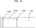
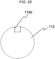
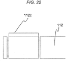
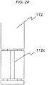
- a hollow 112d may be formed as illustrated in FIGS. 19 and 20 , or a protrusion 112e may be formed as illustrated in FIGS. 21 , 22 , and 23 . In such a configuration, it is possible to obtain the same effects as those of the truncated portion 112c.
- FIGS. 25 to 35 An example useful to understand the present invention will be described with reference to FIGS. 25 to 35 . Note that like reference numerals denote like elements as in the first to third embodiments, and they will not be described repeatedly.
- the first and second fixing portions have shapes different from those of the first to third embodiments.
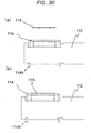
- the first fixing portion 114a has a pair of plates straightly extending in parallel such that they can be inserted into holes of the movable object 112 to allow fixation.
- tip portions 114h have a hook shape.
- the target 110 can be fixed to the shaft 112.
- the first fixing portion 114a has a base portion 114i having an R-shape which is a relief shape. By virtue of this relief shape, the first fixing portion 114a can be easily deformed when installing the target 110 in the shaft 112. Therefore, installability is improved.
- the second fixing portion 114b has the same shape as that of the first fixing portion.
- the shaft 112 where the target 110 is installed is provided with a truncated portion 112c, a first hole 112f, and a second hole 112g.
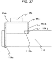
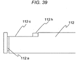
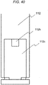
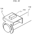
- FIGS. 36 to 45 A fourth embodiment of the present invention will be described with reference to FIGS. 36 to 45 . Note that like reference numerals denote like elements as in the first to third embodiments, and they will not be described repeatedly.
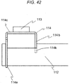
- the second fixing portion 114b has a shape different from those of the first to third embodiments.
- the second fixing portion 114b is provided with a hollow 114j fitted to the protrusion 112h of the movable object 112. As a result, a movement in a twist direction is restricted. According to this embodiment, it is possible to fix the target 110 to the movable object 112 while simplifying the configuration of the second fixing portion 114b.
- the second fixing portion 114b is provided with a protrusion 114k fitted to the hollow 112e of the movable object 112 as illustrated in FIGS. 41 to 45 .
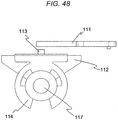
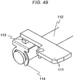
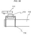
- the target 110 can also be easily installed on a movable object 112 even when the movable object has a cylindrical portion provided with a cavity such as a pulley, and a shaft 1 is inserted into the cylindrical portion so that the cylindrical portion moves along the shaft as illustrated in FIGS. 46 to 48 .
- the target 110 can also be easily installed in a movable object even when the movable object has a cylindrical portion such as a pulley and a shaft is arranged inside the cylindrical portion.
- the target can be easily installed from a direction perpendicular to the axial direction. Therefore, it is possible to improve freedom in installation.
- it is not necessary to form an installation portion for installation on the outside in the axial direction. Therefore, this contributes to miniaturization as a whole.
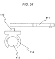
- the magnetic sensor 111 is arranged perpendicularly to the magnet 113 as illustrated in FIG. 1 .
- the magnetic sensor 111 may be arranged in parallel with the magnet 113 as illustrated in FIGS. 45 to 51 .
Landscapes
- Engineering & Computer Science (AREA)
- General Engineering & Computer Science (AREA)
- Physics & Mathematics (AREA)
- General Physics & Mathematics (AREA)
- Mechanical Engineering (AREA)
- Transmission And Conversion Of Sensor Element Output (AREA)
- Measurement Of Length, Angles, Or The Like Using Electric Or Magnetic Means (AREA)
Claims (13)
- Positionssensor mit einem Magnetsensor (111) und einem Zielobjekt (110), das dazu konfiguriert ist, auf einem bewegbaren Objekt (112) installiert zu werden, wobei
das Zielobjekt (110) einen Magnet (113) und eine Magnetbasis (114) aufweist, die den Magnet (113) hält,
die Magnetbasis (114) einen Magnethalteabschnitt (114c) und einen Befestigungsabschnitt (114a, 114b) zur Befestigung des bewegbaren Objekts (112) aufweist, wobei der Magnethalteabschnitt (114c) und der Befestigungsabschnitt (114a, 114b) einstückig ausgebildet sind,
der Befestigungsabschnitt (114a, 114b) einen ersten Befestigungsabschnitt (114a) und einen zweiten Befestigungsabschnitt (114b) aufweist, und
der erste Befestigungsabschnitt (114a) eine teilweise offene Ringform hat,
dadurch gekennzeichnet, dass der erste Befestigungsabschnitt (114a) erste, zweite und dritte Kontaktabschnitte (114d, 114e, 114f) aufweist, die so ausgebildet sind, dass Zentren jedes Kontaktabschnitts, der in Kontakt mit dem bewegbaren Objekt (112) kommt, ein gleichseitiges Dreieck bilden. - Positionssensor, nach Anspruch 1, wobei
der erste Kontaktabschnitt (114d) entfernt von einer Öffnung (114g) des ersten Befestigungsabschnitts (114a) gebildet ist,
der zweite und der dritte Kontaktabschnitt (114e, 114f) angrenzend an die Öffnung (114g) ausgebildet sind,
der erste Kontaktabschnitt (114d) so geformt ist, dass er einen flachen Abschnitt aufweist, und
der zweite und der dritte Kontaktabschnitt (114e, 114f) eine Bogenform aufweisen. - Positionssensor nach Anspruch 2, wobei der erste Befestigungsabschnitt (114a) aufweist:einen, zwischen dem ersten und dem zweiten Kontaktabschnitt (114d, 114e) angeordneten, ersten Nicht-Kontakt-Abschnitt, der nicht in Kontakt mit dem bewegbaren Objekt (112) kommt, undeinen, zwischen dem ersten und dem dritten Kontaktabschnitt (114d, 114f) angeordneten, zweiten Nicht-Kontakt-Abschnitt, der nicht in Kontakt mit dem bewegbaren Objekt (112) kommt.
- Positionssensor nach Anspruch 3, wobei die Öffnung (114g) des ersten Befestigungsabschnitts (114a) eine Keilform aufweist, die sich graduell von einem Öffnungsende zu einer Innenseite verjüngt.
- Positionssensor nach einem der vorstehenden Ansprüche, wobei der zweite Befestigungsabschnitt (114b) eine ähnliche Form aufweist wie der erste Befestigungsabschnitt (114a).
- Positionssensor nach einem der vorstehenden Ansprüche, wobei der zweite Befestigungsabschnitt (114b) so geformt ist, dass er
einen Vorsprung (114k) aufweist, der in einen Hohlraum (112e) passt, der in dem bewegbaren Objekt (112) ausgebildet ist, oder
einen Hohlraum (114j) aufweist, in den ein Vorsprung (112h) passt, der an dem bewegbaren Objekt (112) ausgebildet ist. - Positionsmessanordnung mit dem Positionssensor nach Anspruch 1 und dem bewegbaren Objekt (112), wobei
das bewegbare Objekt (112) eine Nut (112a, 112b) aufweist, die längs einer Umfangsrichtung ausgebildet ist, und
das Zielobjekt (110) an dem bewegbaren Objekt (112) befestigt ist, indem der Befestigungsabschnitt (114a, 114b) in die Nut (112a, 112b) eingepasst ist. - Positionsmessanordnung mit dem Positionssensor nach Anspruch 5 und dem bewegbaren Objekt (112), wobei
das bewegbare Objekt (112) eine erste und eine zweite Nut (112a, 112b) aufweist, die längs einer Umfangsrichtung ausgebildet sind,
die erste Nut (112a) einen teilweise abgeflachten Abschnitt (112c) aufweist,
das Zielobjekt (110) an dem bewegbaren Objekt (112) befestigt ist, indem der erste Befestigungsabschnitt (114a) in die erste Nut (112a) und der zweite Befestigungsabschnitt (114b) in die zweite Nut (112b) eingepasst ist, und
der erste Kontaktabschnitt (114d) in Kontakt mit dem abgeflachten Abschnitt (112c) kommt. - Positionsmessanordnung mit dem Positionssensor nach Anspruch 5 und dem bewegbaren Objekt (112), wobei
das bewegbare Objekt (112) eine erste und eine zweite Nut (112a, 112b) aufweist, die längs einer Umfangsrichtung gebildet sind,
ein abgeflachter Flachabschnitt (112c) zwischen der ersten und der zweiten Nut (112a, 112b) ausgebildet ist,
das Zielobjekt (110) an dem bewegbaren Objekt (112) befestigt ist, indem der erste Befestigungsabschnitt (114a) in die erste Nut (112a) und der zweite Befestigungsabschnitt (114b) in die zweite Nut (112b) eingepasst ist, und
der Magnethalteabschnitt (114c) in einer Position befestigt ist, in der er dem Flachabschnitt (112c) zugewandt ist. - Positionssensor nach einem der Ansprüche 1 bis 6, oder Positionsmessanordnung nach einem der Ansprüche 7 bis 9, ferner mit einer Basisabdeckung (115), die den Magnet (113) abdeckt, wobei die Magnetbasis (114) einen Gehäusehohlraum aufweist, der in dem Magnethalteabschnitt (114c) gebildet ist, und der Magnet (113) in dem Gehäusehohlraum angeordnet ist.
- Positionssensor nach einem der Ansprüche 1 bis 6 oder Positionsmessanordnung nach einem der Ansprüche 7 bis 9, ferner mit einer Basisabdeckung (115), die den Magnet (113) abdeckt, wobei die Basisabdeckung (115) mit einem Gehäusehohlraum versehen ist, in dem der Magnet (113) untergebracht ist.
- Positionssensor oder Positionsmessanordnung nach Anspruch 10 oder 11, wobei die Magnetbasis (114) mit einem Hohlraum (117) oder einem Vorsprung (116) versehen ist, der zu einem in der Basisabdeckung (115) ausgebildeten Positionierungsvorsprung (116) oder Positionierungshohlraum (117) passt.
- Positionssensor nach einem der Ansprüche 1 bis 5, wobei das Zielobjekt (110) dazu konfiguriert ist, an dem bewegbaren Objekt (112) installiert zu werden, das sich in einer Axialrichtung bewegt und mit dem Magnet (113) versehen ist, der eine durch den Magnetsensor (111) erfasste Magnetkraft erzeugt.
Applications Claiming Priority (2)
| Application Number | Priority Date | Filing Date | Title |
|---|---|---|---|
| JP2015169984 | 2015-08-31 | ||
| PCT/JP2016/071955 WO2017038318A1 (ja) | 2015-08-31 | 2016-07-27 | ポジションセンサ |
Publications (3)
| Publication Number | Publication Date |
|---|---|
| EP3346239A1 EP3346239A1 (de) | 2018-07-11 |
| EP3346239A4 EP3346239A4 (de) | 2019-04-03 |
| EP3346239B1 true EP3346239B1 (de) | 2020-04-08 |
Family
ID=58187334
Family Applications (1)
| Application Number | Title | Priority Date | Filing Date |
|---|---|---|---|
| EP16841350.8A Active EP3346239B1 (de) | 2015-08-31 | 2016-07-27 | Positionssensor |
Country Status (5)
| Country | Link |
|---|---|
| US (1) | US20180202836A1 (de) |
| EP (1) | EP3346239B1 (de) |
| JP (1) | JP6473822B2 (de) |
| CN (1) | CN107923763B (de) |
| WO (1) | WO2017038318A1 (de) |
Families Citing this family (4)
| Publication number | Priority date | Publication date | Assignee | Title |
|---|---|---|---|---|
| JP6696811B2 (ja) * | 2016-03-30 | 2020-05-20 | Ntn株式会社 | センサターゲットとこのターゲットを備えた可動部ユニット、並びに電動アクチュエータ |
| JP6669184B2 (ja) * | 2018-03-14 | 2020-03-18 | Tdk株式会社 | シャフトユニットおよびその製造方法、位置検出装置、ならびに磁気部材 |
| CN109115105B (zh) * | 2018-07-27 | 2020-08-14 | 合肥工业大学 | 一种轴用挡圈与轴槽接触状态监测装置 |
| US11555719B2 (en) * | 2018-12-12 | 2023-01-17 | Hl Mando Corporation | Actuator assembly having rotary sensor responsive to rotation of magnet |
Family Cites Families (13)
| Publication number | Priority date | Publication date | Assignee | Title |
|---|---|---|---|---|
| US5789917A (en) * | 1990-12-05 | 1998-08-04 | Moving Magnet Technologie Sa | Magnetic position sensor with hall probe formed in an air gap of a stator |
| US6124710A (en) * | 1998-11-13 | 2000-09-26 | Cts Corporation | Rotary magnetic encoder using hall effect for detecting revolution of a shaft |
| JP3596667B2 (ja) * | 2000-01-26 | 2004-12-02 | 株式会社デンソー | 回転角検出装置 |
| JP4590785B2 (ja) * | 2001-06-19 | 2010-12-01 | パナソニック株式会社 | 非接触型位置センサ |
| JP4007313B2 (ja) * | 2003-01-22 | 2007-11-14 | 株式会社村田製作所 | 角度センサ |
| JP4201654B2 (ja) * | 2003-06-18 | 2008-12-24 | 栄通信工業株式会社 | 磁気式ポテンショメータ |
| JP4578159B2 (ja) * | 2004-06-22 | 2010-11-10 | アルプス電気株式会社 | ポジションセンサ |
| KR101057951B1 (ko) * | 2006-04-27 | 2011-08-18 | 아사히 가세이 일렉트로닉스 가부시끼가이샤 | 위치 검출 장치 및 위치 검출 방법 |
| CN202101680U (zh) * | 2008-11-26 | 2012-01-04 | Cts公司 | 带有抗转器的线性位置传感器 |
| JP2014052281A (ja) * | 2012-09-07 | 2014-03-20 | Tokai Rika Co Ltd | 2軸ポジションセンサ及びそれを用いたシフトポジションセンサ |
| CN104797806B (zh) * | 2012-11-12 | 2017-06-30 | 日产自动车株式会社 | 非磁性体的组装构造 |
| JP2015125103A (ja) * | 2013-12-27 | 2015-07-06 | 日本精機株式会社 | ストロークセンサ |
| JP2016099187A (ja) * | 2014-11-20 | 2016-05-30 | アイシン精機株式会社 | 回転角検出装置 |
-
2016
- 2016-07-27 EP EP16841350.8A patent/EP3346239B1/de active Active
- 2016-07-27 WO PCT/JP2016/071955 patent/WO2017038318A1/ja not_active Ceased
- 2016-07-27 JP JP2017537659A patent/JP6473822B2/ja active Active
- 2016-07-27 CN CN201680047138.4A patent/CN107923763B/zh active Active
- 2016-07-27 US US15/743,957 patent/US20180202836A1/en not_active Abandoned
Non-Patent Citations (1)
| Title |
|---|
| None * |
Also Published As
| Publication number | Publication date |
|---|---|
| EP3346239A1 (de) | 2018-07-11 |
| JPWO2017038318A1 (ja) | 2018-03-01 |
| US20180202836A1 (en) | 2018-07-19 |
| JP6473822B2 (ja) | 2019-02-20 |
| CN107923763B (zh) | 2020-11-06 |
| CN107923763A (zh) | 2018-04-17 |
| WO2017038318A1 (ja) | 2017-03-09 |
| EP3346239A4 (de) | 2019-04-03 |
Similar Documents
| Publication | Publication Date | Title |
|---|---|---|
| EP3346239A1 (de) | Positionssensor | |
| EP3239678B1 (de) | Drehmomentdetektor | |
| US8914952B2 (en) | Clip | |
| EP2657545B1 (de) | Zweiteilige klammer | |
| US20150219187A1 (en) | Reduction motor | |
| US9341210B2 (en) | Fastener | |
| US11273866B2 (en) | Torque sensor and electric power steering system | |
| JP5862615B2 (ja) | レゾルバステータおよびその固定構造 | |
| WO2018147012A1 (ja) | モータ | |
| CN108696087B (zh) | 旋转变压器定子 | |
| EP4394196A1 (de) | Objekthaltestruktur | |
| JP2010286007A (ja) | 変速機 | |
| JP5867865B2 (ja) | シリンダの取付構造 | |
| CN110770474B (zh) | 滚珠丝杠 | |
| US20240191747A1 (en) | Bearing housing assembly and ring configured to provide multiple modes of operation | |
| CN104838153B (zh) | 用于齿轮机构位置传感器布置的磁体保持构件和锁紧套筒 | |
| US11060931B2 (en) | Sensor device | |
| US20140286144A1 (en) | System for attaching a wristlet strand to a case | |
| JP6469415B2 (ja) | モータおよび回転軸への従動部材の固定構造 | |
| JP2006258542A (ja) | 回転センサ付き軸受装置 | |
| KR20110048026A (ko) | 필기구의 클립 부착 구조 | |
| JP2015104236A (ja) | レゾルバ | |
| US9696334B2 (en) | Wheel speed sensor | |
| JP2018036206A (ja) | センサ装置 | |
| KR100985933B1 (ko) | 차량용 후방감지센서 조립체 |
Legal Events
| Date | Code | Title | Description |
|---|---|---|---|
| STAA | Information on the status of an ep patent application or granted ep patent |
Free format text: STATUS: THE INTERNATIONAL PUBLICATION HAS BEEN MADE |
|
| PUAI | Public reference made under article 153(3) epc to a published international application that has entered the european phase |
Free format text: ORIGINAL CODE: 0009012 |
|
| STAA | Information on the status of an ep patent application or granted ep patent |
Free format text: STATUS: REQUEST FOR EXAMINATION WAS MADE |
|
| 17P | Request for examination filed |
Effective date: 20171128 |
|
| AK | Designated contracting states |
Kind code of ref document: A1 Designated state(s): AL AT BE BG CH CY CZ DE DK EE ES FI FR GB GR HR HU IE IS IT LI LT LU LV MC MK MT NL NO PL PT RO RS SE SI SK SM TR |
|
| AX | Request for extension of the european patent |
Extension state: BA ME |
|
| DAV | Request for validation of the european patent (deleted) | ||
| DAX | Request for extension of the european patent (deleted) | ||
| A4 | Supplementary search report drawn up and despatched |
Effective date: 20190306 |
|
| RIC1 | Information provided on ipc code assigned before grant |
Ipc: F16B 21/18 20060101ALI20190228BHEP Ipc: G01D 5/16 20060101ALI20190228BHEP Ipc: G01D 5/12 20060101AFI20190228BHEP Ipc: G01D 5/14 20060101ALI20190228BHEP Ipc: G01D 11/24 20060101ALI20190228BHEP |
|
| GRAP | Despatch of communication of intention to grant a patent |
Free format text: ORIGINAL CODE: EPIDOSNIGR1 |
|
| STAA | Information on the status of an ep patent application or granted ep patent |
Free format text: STATUS: GRANT OF PATENT IS INTENDED |
|
| RIC1 | Information provided on ipc code assigned before grant |
Ipc: G01D 5/16 20060101ALI20191129BHEP Ipc: G01D 11/24 20060101ALI20191129BHEP Ipc: F16B 21/18 20060101ALI20191129BHEP Ipc: G01D 5/12 20060101AFI20191129BHEP Ipc: G01D 5/14 20060101ALI20191129BHEP |
|
| INTG | Intention to grant announced |
Effective date: 20200107 |
|
| GRAS | Grant fee paid |
Free format text: ORIGINAL CODE: EPIDOSNIGR3 |
|
| GRAA | (expected) grant |
Free format text: ORIGINAL CODE: 0009210 |
|
| STAA | Information on the status of an ep patent application or granted ep patent |
Free format text: STATUS: THE PATENT HAS BEEN GRANTED |
|
| AK | Designated contracting states |
Kind code of ref document: B1 Designated state(s): AL AT BE BG CH CY CZ DE DK EE ES FI FR GB GR HR HU IE IS IT LI LT LU LV MC MK MT NL NO PL PT RO RS SE SI SK SM TR |
|
| REG | Reference to a national code |
Ref country code: CH Ref legal event code: EP Ref country code: AT Ref legal event code: REF Ref document number: 1254996 Country of ref document: AT Kind code of ref document: T Effective date: 20200415 |
|
| REG | Reference to a national code |
Ref country code: DE Ref legal event code: R096 Ref document number: 602016033816 Country of ref document: DE |
|
| REG | Reference to a national code |
Ref country code: IE Ref legal event code: FG4D |
|
| REG | Reference to a national code |
Ref country code: NL Ref legal event code: MP Effective date: 20200408 |
|
| REG | Reference to a national code |
Ref country code: LT Ref legal event code: MG4D |
|
| PG25 | Lapsed in a contracting state [announced via postgrant information from national office to epo] |
Ref country code: IS Free format text: LAPSE BECAUSE OF FAILURE TO SUBMIT A TRANSLATION OF THE DESCRIPTION OR TO PAY THE FEE WITHIN THE PRESCRIBED TIME-LIMIT Effective date: 20200808 Ref country code: NO Free format text: LAPSE BECAUSE OF FAILURE TO SUBMIT A TRANSLATION OF THE DESCRIPTION OR TO PAY THE FEE WITHIN THE PRESCRIBED TIME-LIMIT Effective date: 20200708 Ref country code: SE Free format text: LAPSE BECAUSE OF FAILURE TO SUBMIT A TRANSLATION OF THE DESCRIPTION OR TO PAY THE FEE WITHIN THE PRESCRIBED TIME-LIMIT Effective date: 20200408 Ref country code: GR Free format text: LAPSE BECAUSE OF FAILURE TO SUBMIT A TRANSLATION OF THE DESCRIPTION OR TO PAY THE FEE WITHIN THE PRESCRIBED TIME-LIMIT Effective date: 20200709 Ref country code: FI Free format text: LAPSE BECAUSE OF FAILURE TO SUBMIT A TRANSLATION OF THE DESCRIPTION OR TO PAY THE FEE WITHIN THE PRESCRIBED TIME-LIMIT Effective date: 20200408 Ref country code: LT Free format text: LAPSE BECAUSE OF FAILURE TO SUBMIT A TRANSLATION OF THE DESCRIPTION OR TO PAY THE FEE WITHIN THE PRESCRIBED TIME-LIMIT Effective date: 20200408 Ref country code: PT Free format text: LAPSE BECAUSE OF FAILURE TO SUBMIT A TRANSLATION OF THE DESCRIPTION OR TO PAY THE FEE WITHIN THE PRESCRIBED TIME-LIMIT Effective date: 20200817 Ref country code: NL Free format text: LAPSE BECAUSE OF FAILURE TO SUBMIT A TRANSLATION OF THE DESCRIPTION OR TO PAY THE FEE WITHIN THE PRESCRIBED TIME-LIMIT Effective date: 20200408 |
|
| REG | Reference to a national code |
Ref country code: AT Ref legal event code: MK05 Ref document number: 1254996 Country of ref document: AT Kind code of ref document: T Effective date: 20200408 |
|
| PG25 | Lapsed in a contracting state [announced via postgrant information from national office to epo] |
Ref country code: LV Free format text: LAPSE BECAUSE OF FAILURE TO SUBMIT A TRANSLATION OF THE DESCRIPTION OR TO PAY THE FEE WITHIN THE PRESCRIBED TIME-LIMIT Effective date: 20200408 Ref country code: BG Free format text: LAPSE BECAUSE OF FAILURE TO SUBMIT A TRANSLATION OF THE DESCRIPTION OR TO PAY THE FEE WITHIN THE PRESCRIBED TIME-LIMIT Effective date: 20200708 Ref country code: HR Free format text: LAPSE BECAUSE OF FAILURE TO SUBMIT A TRANSLATION OF THE DESCRIPTION OR TO PAY THE FEE WITHIN THE PRESCRIBED TIME-LIMIT Effective date: 20200408 Ref country code: RS Free format text: LAPSE BECAUSE OF FAILURE TO SUBMIT A TRANSLATION OF THE DESCRIPTION OR TO PAY THE FEE WITHIN THE PRESCRIBED TIME-LIMIT Effective date: 20200408 |
|
| PG25 | Lapsed in a contracting state [announced via postgrant information from national office to epo] |
Ref country code: AL Free format text: LAPSE BECAUSE OF FAILURE TO SUBMIT A TRANSLATION OF THE DESCRIPTION OR TO PAY THE FEE WITHIN THE PRESCRIBED TIME-LIMIT Effective date: 20200408 |
|
| REG | Reference to a national code |
Ref country code: DE Ref legal event code: R097 Ref document number: 602016033816 Country of ref document: DE |
|
| PG25 | Lapsed in a contracting state [announced via postgrant information from national office to epo] |
Ref country code: SM Free format text: LAPSE BECAUSE OF FAILURE TO SUBMIT A TRANSLATION OF THE DESCRIPTION OR TO PAY THE FEE WITHIN THE PRESCRIBED TIME-LIMIT Effective date: 20200408 Ref country code: IT Free format text: LAPSE BECAUSE OF FAILURE TO SUBMIT A TRANSLATION OF THE DESCRIPTION OR TO PAY THE FEE WITHIN THE PRESCRIBED TIME-LIMIT Effective date: 20200408 Ref country code: EE Free format text: LAPSE BECAUSE OF FAILURE TO SUBMIT A TRANSLATION OF THE DESCRIPTION OR TO PAY THE FEE WITHIN THE PRESCRIBED TIME-LIMIT Effective date: 20200408 Ref country code: DK Free format text: LAPSE BECAUSE OF FAILURE TO SUBMIT A TRANSLATION OF THE DESCRIPTION OR TO PAY THE FEE WITHIN THE PRESCRIBED TIME-LIMIT Effective date: 20200408 Ref country code: ES Free format text: LAPSE BECAUSE OF FAILURE TO SUBMIT A TRANSLATION OF THE DESCRIPTION OR TO PAY THE FEE WITHIN THE PRESCRIBED TIME-LIMIT Effective date: 20200408 Ref country code: AT Free format text: LAPSE BECAUSE OF FAILURE TO SUBMIT A TRANSLATION OF THE DESCRIPTION OR TO PAY THE FEE WITHIN THE PRESCRIBED TIME-LIMIT Effective date: 20200408 Ref country code: RO Free format text: LAPSE BECAUSE OF FAILURE TO SUBMIT A TRANSLATION OF THE DESCRIPTION OR TO PAY THE FEE WITHIN THE PRESCRIBED TIME-LIMIT Effective date: 20200408 Ref country code: CZ Free format text: LAPSE BECAUSE OF FAILURE TO SUBMIT A TRANSLATION OF THE DESCRIPTION OR TO PAY THE FEE WITHIN THE PRESCRIBED TIME-LIMIT Effective date: 20200408 |
|
| PLBE | No opposition filed within time limit |
Free format text: ORIGINAL CODE: 0009261 |
|
| STAA | Information on the status of an ep patent application or granted ep patent |
Free format text: STATUS: NO OPPOSITION FILED WITHIN TIME LIMIT |
|
| PG25 | Lapsed in a contracting state [announced via postgrant information from national office to epo] |
Ref country code: PL Free format text: LAPSE BECAUSE OF FAILURE TO SUBMIT A TRANSLATION OF THE DESCRIPTION OR TO PAY THE FEE WITHIN THE PRESCRIBED TIME-LIMIT Effective date: 20200408 Ref country code: MC Free format text: LAPSE BECAUSE OF FAILURE TO SUBMIT A TRANSLATION OF THE DESCRIPTION OR TO PAY THE FEE WITHIN THE PRESCRIBED TIME-LIMIT Effective date: 20200408 Ref country code: SK Free format text: LAPSE BECAUSE OF FAILURE TO SUBMIT A TRANSLATION OF THE DESCRIPTION OR TO PAY THE FEE WITHIN THE PRESCRIBED TIME-LIMIT Effective date: 20200408 |
|
| REG | Reference to a national code |
Ref country code: CH Ref legal event code: PL |
|
| 26N | No opposition filed |
Effective date: 20210112 |
|
| REG | Reference to a national code |
Ref country code: DE Ref legal event code: R082 Ref document number: 602016033816 Country of ref document: DE Representative=s name: STREHL SCHUEBEL-HOPF & PARTNER MBB PATENTANWAE, DE Ref country code: DE Ref legal event code: R081 Ref document number: 602016033816 Country of ref document: DE Owner name: HITACHI ASTEMO, LTD., HITACHINAKA-SHI, JP Free format text: FORMER OWNER: HITACHI AUTOMOTIVE SYSTEMS, LTD., HITACHINAKA-SHI, IBARAKI, JP |
|
| GBPC | Gb: european patent ceased through non-payment of renewal fee |
Effective date: 20200727 |
|
| REG | Reference to a national code |
Ref country code: BE Ref legal event code: MM Effective date: 20200731 |
|
| PG25 | Lapsed in a contracting state [announced via postgrant information from national office to epo] |
Ref country code: CH Free format text: LAPSE BECAUSE OF NON-PAYMENT OF DUE FEES Effective date: 20200731 Ref country code: LU Free format text: LAPSE BECAUSE OF NON-PAYMENT OF DUE FEES Effective date: 20200727 Ref country code: LI Free format text: LAPSE BECAUSE OF NON-PAYMENT OF DUE FEES Effective date: 20200731 Ref country code: FR Free format text: LAPSE BECAUSE OF NON-PAYMENT OF DUE FEES Effective date: 20200731 Ref country code: GB Free format text: LAPSE BECAUSE OF NON-PAYMENT OF DUE FEES Effective date: 20200727 |
|
| PG25 | Lapsed in a contracting state [announced via postgrant information from national office to epo] |
Ref country code: BE Free format text: LAPSE BECAUSE OF NON-PAYMENT OF DUE FEES Effective date: 20200731 Ref country code: SI Free format text: LAPSE BECAUSE OF FAILURE TO SUBMIT A TRANSLATION OF THE DESCRIPTION OR TO PAY THE FEE WITHIN THE PRESCRIBED TIME-LIMIT Effective date: 20200408 |
|
| PG25 | Lapsed in a contracting state [announced via postgrant information from national office to epo] |
Ref country code: IE Free format text: LAPSE BECAUSE OF NON-PAYMENT OF DUE FEES Effective date: 20200727 |
|
| PG25 | Lapsed in a contracting state [announced via postgrant information from national office to epo] |
Ref country code: TR Free format text: LAPSE BECAUSE OF FAILURE TO SUBMIT A TRANSLATION OF THE DESCRIPTION OR TO PAY THE FEE WITHIN THE PRESCRIBED TIME-LIMIT Effective date: 20200408 Ref country code: MT Free format text: LAPSE BECAUSE OF FAILURE TO SUBMIT A TRANSLATION OF THE DESCRIPTION OR TO PAY THE FEE WITHIN THE PRESCRIBED TIME-LIMIT Effective date: 20200408 Ref country code: CY Free format text: LAPSE BECAUSE OF FAILURE TO SUBMIT A TRANSLATION OF THE DESCRIPTION OR TO PAY THE FEE WITHIN THE PRESCRIBED TIME-LIMIT Effective date: 20200408 |
|
| PG25 | Lapsed in a contracting state [announced via postgrant information from national office to epo] |
Ref country code: MK Free format text: LAPSE BECAUSE OF FAILURE TO SUBMIT A TRANSLATION OF THE DESCRIPTION OR TO PAY THE FEE WITHIN THE PRESCRIBED TIME-LIMIT Effective date: 20200408 |
|
| PGFP | Annual fee paid to national office [announced via postgrant information from national office to epo] |
Ref country code: DE Payment date: 20250604 Year of fee payment: 10 |