EP3344147B1 - Ultrasound transducer assembly - Google Patents
Ultrasound transducer assembly Download PDFInfo
- Publication number
- EP3344147B1 EP3344147B1 EP16843099.9A EP16843099A EP3344147B1 EP 3344147 B1 EP3344147 B1 EP 3344147B1 EP 16843099 A EP16843099 A EP 16843099A EP 3344147 B1 EP3344147 B1 EP 3344147B1
- Authority
- EP
- European Patent Office
- Prior art keywords
- kerfs
- transducer assembly
- layer
- transducer
- width
- Prior art date
- Legal status (The legal status is an assumption and is not a legal conclusion. Google has not performed a legal analysis and makes no representation as to the accuracy of the status listed.)
- Active
Links
Images


Classifications
-
- A—HUMAN NECESSITIES
- A61—MEDICAL OR VETERINARY SCIENCE; HYGIENE
- A61B—DIAGNOSIS; SURGERY; IDENTIFICATION
- A61B8/00—Diagnosis using ultrasonic, sonic or infrasonic waves
- A61B8/44—Constructional features of the ultrasonic, sonic or infrasonic diagnostic device
- A61B8/4483—Constructional features of the ultrasonic, sonic or infrasonic diagnostic device characterised by features of the ultrasound transducer
- A61B8/4488—Constructional features of the ultrasonic, sonic or infrasonic diagnostic device characterised by features of the ultrasound transducer the transducer being a phased array
-
- A—HUMAN NECESSITIES
- A61—MEDICAL OR VETERINARY SCIENCE; HYGIENE
- A61B—DIAGNOSIS; SURGERY; IDENTIFICATION
- A61B8/00—Diagnosis using ultrasonic, sonic or infrasonic waves
- A61B8/44—Constructional features of the ultrasonic, sonic or infrasonic diagnostic device
- A61B8/4483—Constructional features of the ultrasonic, sonic or infrasonic diagnostic device characterised by features of the ultrasound transducer
- A61B8/4494—Constructional features of the ultrasonic, sonic or infrasonic diagnostic device characterised by features of the ultrasound transducer characterised by the arrangement of the transducer elements
-
- B—PERFORMING OPERATIONS; TRANSPORTING
- B06—GENERATING OR TRANSMITTING MECHANICAL VIBRATIONS IN GENERAL
- B06B—METHODS OR APPARATUS FOR GENERATING OR TRANSMITTING MECHANICAL VIBRATIONS OF INFRASONIC, SONIC, OR ULTRASONIC FREQUENCY, e.g. FOR PERFORMING MECHANICAL WORK IN GENERAL
- B06B1/00—Methods or apparatus for generating mechanical vibrations of infrasonic, sonic, or ultrasonic frequency
- B06B1/02—Methods or apparatus for generating mechanical vibrations of infrasonic, sonic, or ultrasonic frequency making use of electrical energy
- B06B1/06—Methods or apparatus for generating mechanical vibrations of infrasonic, sonic, or ultrasonic frequency making use of electrical energy operating with piezoelectric effect or with electrostriction
- B06B1/0607—Methods or apparatus for generating mechanical vibrations of infrasonic, sonic, or ultrasonic frequency making use of electrical energy operating with piezoelectric effect or with electrostriction using multiple elements
- B06B1/0622—Methods or apparatus for generating mechanical vibrations of infrasonic, sonic, or ultrasonic frequency making use of electrical energy operating with piezoelectric effect or with electrostriction using multiple elements on one surface
-
- B—PERFORMING OPERATIONS; TRANSPORTING
- B06—GENERATING OR TRANSMITTING MECHANICAL VIBRATIONS IN GENERAL
- B06B—METHODS OR APPARATUS FOR GENERATING OR TRANSMITTING MECHANICAL VIBRATIONS OF INFRASONIC, SONIC, OR ULTRASONIC FREQUENCY, e.g. FOR PERFORMING MECHANICAL WORK IN GENERAL
- B06B1/00—Methods or apparatus for generating mechanical vibrations of infrasonic, sonic, or ultrasonic frequency
- B06B1/02—Methods or apparatus for generating mechanical vibrations of infrasonic, sonic, or ultrasonic frequency making use of electrical energy
- B06B1/06—Methods or apparatus for generating mechanical vibrations of infrasonic, sonic, or ultrasonic frequency making use of electrical energy operating with piezoelectric effect or with electrostriction
- B06B1/0644—Methods or apparatus for generating mechanical vibrations of infrasonic, sonic, or ultrasonic frequency making use of electrical energy operating with piezoelectric effect or with electrostriction using a single piezoelectric element
- B06B1/0662—Methods or apparatus for generating mechanical vibrations of infrasonic, sonic, or ultrasonic frequency making use of electrical energy operating with piezoelectric effect or with electrostriction using a single piezoelectric element with an electrode on the sensitive surface
- B06B1/067—Methods or apparatus for generating mechanical vibrations of infrasonic, sonic, or ultrasonic frequency making use of electrical energy operating with piezoelectric effect or with electrostriction using a single piezoelectric element with an electrode on the sensitive surface which is used as, or combined with, an impedance matching layer
-
- G—PHYSICS
- G01—MEASURING; TESTING
- G01N—INVESTIGATING OR ANALYSING MATERIALS BY DETERMINING THEIR CHEMICAL OR PHYSICAL PROPERTIES
- G01N29/00—Investigating or analysing materials by the use of ultrasonic, sonic or infrasonic waves; Visualisation of the interior of objects by transmitting ultrasonic or sonic waves through the object
- G01N29/22—Details, e.g. general constructional or apparatus details
- G01N29/24—Probes
- G01N29/2406—Electrostatic or capacitive probes, e.g. electret or cMUT-probes
-
- G—PHYSICS
- G01—MEASURING; TESTING
- G01N—INVESTIGATING OR ANALYSING MATERIALS BY DETERMINING THEIR CHEMICAL OR PHYSICAL PROPERTIES
- G01N29/00—Investigating or analysing materials by the use of ultrasonic, sonic or infrasonic waves; Visualisation of the interior of objects by transmitting ultrasonic or sonic waves through the object
- G01N29/22—Details, e.g. general constructional or apparatus details
- G01N29/24—Probes
- G01N29/2437—Piezoelectric probes
-
- H—ELECTRICITY
- H10—SEMICONDUCTOR DEVICES; ELECTRIC SOLID-STATE DEVICES NOT OTHERWISE PROVIDED FOR
- H10N—ELECTRIC SOLID-STATE DEVICES NOT OTHERWISE PROVIDED FOR
- H10N30/00—Piezoelectric or electrostrictive devices
- H10N30/01—Manufacture or treatment
- H10N30/07—Forming of piezoelectric or electrostrictive parts or bodies on an electrical element or another base
- H10N30/072—Forming of piezoelectric or electrostrictive parts or bodies on an electrical element or another base by laminating or bonding of piezoelectric or electrostrictive bodies
-
- H—ELECTRICITY
- H10—SEMICONDUCTOR DEVICES; ELECTRIC SOLID-STATE DEVICES NOT OTHERWISE PROVIDED FOR
- H10N—ELECTRIC SOLID-STATE DEVICES NOT OTHERWISE PROVIDED FOR
- H10N30/00—Piezoelectric or electrostrictive devices
- H10N30/01—Manufacture or treatment
- H10N30/08—Shaping or machining of piezoelectric or electrostrictive bodies
- H10N30/085—Shaping or machining of piezoelectric or electrostrictive bodies by machining
- H10N30/088—Shaping or machining of piezoelectric or electrostrictive bodies by machining by cutting or dicing
-
- H—ELECTRICITY
- H10—SEMICONDUCTOR DEVICES; ELECTRIC SOLID-STATE DEVICES NOT OTHERWISE PROVIDED FOR
- H10N—ELECTRIC SOLID-STATE DEVICES NOT OTHERWISE PROVIDED FOR
- H10N30/00—Piezoelectric or electrostrictive devices
- H10N30/20—Piezoelectric or electrostrictive devices with electrical input and mechanical output, e.g. functioning as actuators or vibrators
- H10N30/206—Piezoelectric or electrostrictive devices with electrical input and mechanical output, e.g. functioning as actuators or vibrators using only longitudinal or thickness displacement, e.g. d33 or d31 type devices
-
- A—HUMAN NECESSITIES
- A61—MEDICAL OR VETERINARY SCIENCE; HYGIENE
- A61B—DIAGNOSIS; SURGERY; IDENTIFICATION
- A61B8/00—Diagnosis using ultrasonic, sonic or infrasonic waves
- A61B8/44—Constructional features of the ultrasonic, sonic or infrasonic diagnostic device
- A61B8/4444—Constructional features of the ultrasonic, sonic or infrasonic diagnostic device related to the probe
-
- G—PHYSICS
- G01—MEASURING; TESTING
- G01N—INVESTIGATING OR ANALYSING MATERIALS BY DETERMINING THEIR CHEMICAL OR PHYSICAL PROPERTIES
- G01N2291/00—Indexing codes associated with group G01N29/00
- G01N2291/02—Indexing codes associated with the analysed material
- G01N2291/023—Solids
- G01N2291/0231—Composite or layered materials
Definitions
- the disclosed technology relates generally to ultrasound transducers, and more specifically ultrasound transducer assemblies configured for use with ultrasound imaging systems.
- EP 0707898 A2 discloses a transducer device with integral transducer and impedance matching portions including grooves formed partially through a thickness of a piezoelectric member.
- a groove volume fraction at the impedance matching portion controls the electrical impedance.
- the impedance matching portion is at either or both of the front and rear surfaces of the transducer portion, which generates acoustic wave energy in response to application of a drive signal.
- the drive signal is introduced by electrodes.
- the electrode at the impedance matching portion extends into the grooves, and a filler material is selected and deposited to allow use of a planar electrode.
- the grooves are filled with filler material.
- the grooves contain internal grooves in the filler material in the matching layer adjacent to the lens, the internal grooves having a width in an azimuthal direction that is less than a width of the grooves in which they are contained and are filled with a second filler material, different than the filler material.
- US 2009/093722 A1 discloses an ultrasonic probe and ultrasonic diagnostic apparatus.
- US 6359375 B1 discloses a method to build a high bandwidth, low crosstalk, low EM noise transducer.
- US 2005/042424 A1 discloses electrically conductive matching layers and methods.
- US 2006/028099 A1 discloses a composite acoustic matching layer.
- JP S61 39700 A discloses manufacture of an ultrasonic probe.
- JP S59 25500 A discloses production of an ultrasonic wave probe.
- the present invention provides ultrasound transducer assemblies as recited in the claims.
- FIG. 1A is a side view of an ultrasound transducer probe 100 having an ultrasound transducer assembly 120.
- the ultrasound transducer assembly may be configured in accordance with an example forming part of the invention.
- FIG. 1B is a schematic isometric side view of a portion of the transducer assembly 120 showing the azimuthal (e.g., along an x-axis), elevation (e.g., along a y-axis) and axial (e.g., along a z-axis) dimensions of the transducer assembly 120.
- the probe 100 includes an enclosure 110 extending between a distal end portion 112 and a proximal end portion 114.
- the enclosure 110 is configured to carry or house system electronics 116 (e.g., one or more processors, integrated circuits, ASICs, FPGAs, beamformers, batteries and/or other power sources) disposed in an interior portion or cavity of the enclosure 110.
- the system electronics 116 are electrically coupled to an ultrasound imaging system 117 via a cable 118 that is attached to the proximal end of the probe by a strain relief element 119.
- a transducer assembly 120 having one or more transducer elements is electrically coupled to the system electronics 116. In operation, the transducer assembly 120 transmits ultrasound energy from the one or more transducer elements toward a subject and receives ultrasound echoes from the subject.
- the ultrasound echoes are converted into electrical signals by the one or more transducer elements and electrically transmitted to the system electronics 116 and to electronics (e.g., one or more processors, memory modules, beamformers, FPGAs) in the ultrasound imaging system 117 configured to process the electrical signals and form one or more ultrasound images.
- electronics e.g., one or more processors, memory modules, beamformers, FPGAs
- Capturing ultrasound data from a subject using an exemplary transducer assembly generally includes generating ultrasound, transmitting ultrasound into the subject, and receiving ultrasound reflected by the subject.
- a wide range of frequencies of ultrasound may be used to capture ultrasound data, such as, for example, low frequency ultrasound (e.g., less than 15 MHz) and/or high frequency ultrasound (e.g., greater than or equal to 15 MHz) can be used.
- low frequency ultrasound e.g., less than 15 MHz
- high frequency ultrasound e.g., greater than or equal to 15 MHz
- Those of ordinary skill in the art can readily determine which frequency range to use based on factors such as, for example, but not limited to, depth of imaging and/or desired resolution.
- FIG. 2 is a schematic section view of the transducer assembly 120 of FIGS. 1A and 1B shown along the 2-2' line shown in FIG. 1B .
- a transducer layer 230 includes one or more transducer elements configured to emit ultrasound energy at a center operating frequency (e.g., between 1 MHz and about 10 MHz).
- the transducer layer 230 ie-comprises a piezoelectric material (e.g., lead zirconate titanate, i.e. PZT).
- the transducer layer 230 comprises a piezoelectric micromachined ultrasound transducer (PMUT) or a capacitive micromachined ultrasound transducer (CMUT).
- the transducer layer 230 comprises an electrostrictive ceramic material.
- the transducer layer 230 comprises another suitable transducer material.
- An acoustic lens 222 overlies the transducer layer 230 and comprises an acoustically transparent material such as, for example, room temperature vulcanization silicone (RTV) or another suitable acoustic material.
- a plurality of matching layers 224 is positioned between the lens 222 and the transducer layer 230.
- a backing layer 240 underlies the transducer layer 230 and is configured to absorb and dissipate acoustic and thermal energy produced by transducer elements of the transducer layer 230.
- the backing layer 240 comprises a loaded epoxy (e.g., an epoxy loaded with tungsten particles) and/or another suitable material having one or more plates (not shown) extending therethrough.
- a dematching layer 234 is positioned between the transducer layer 230 and the backing layer 240.
- the dematching layer 234 is configured to reflect rearward propagating ultrasound energy from the transducer layer 230 (i.e., toward the backing layer 240) back toward the front of the transducer assembly 120 (i.e., toward the lens 222) and away from the backing layer 240.
- the dematching layer 234 comprises tungsten carbide (WC), which has an acoustic impedance of approximately 100 MRayls, which is significantly greater than the acoustic impedance of PZT (approximately 34 MRayls).
- WC tungsten carbide
- the dematching layer 234 includes one or more materials having a lower acoustic impedance than the acoustic impedance of WC (e.g., approximately 100 MRayls) and the transducer layer 230.
- the dematching layer 234 comprises aluminum nitride (AIN), which has an acoustical impedance of approximately 33 MRayls.
- the dematching layer 234 comprises polycrystalline silicon, which has an acoustical impedance of approximately 22 MRayls.
- the dematching layer 234 comprises copper loaded graphite having an acoustical impedance between about 8MRayls and about 15MRayls, or about 10.7MRayls. In some examples, another suitable dematching layer can be used.
- a plurality of matching layers 224 are positioned between the transducer layer 230 and the lens 222.
- an acoustical impedance e.g., between about 20 MRayls and about 35 MRayls
- an acoustical impedance e.g., between about 10 MRayls and about 20 MRayls
- the acoustic impedance of the first matching layer 224A is greater than an acoustical impedance (e.g., between about 5 MRayls and about 10 MRayls) of the second matching layer 224B.
- the acoustical impedance of the second matching layer 224B is greater than an acoustical impedance (between about 2 MRayls and about 5 MRayls) of the third matching layer 224C.
- the transducer assembly 120 includes three matching layers 224. In the invention, the transducer assembly 120 includes at least two matching layers 224. In other embodiments, the transducer assembly 120 includes four or more matching layers 224.
- FIG. 3 is a schematic section view of the transducer assembly 120 of FIG. 1B along the 3-3' line shown in FIG. 1B (i.e., parallel to the azimuthal axis), and configured in accordance with various examples not forming part of the invention.
- a plurality of trenches, grooves or first kerfs 342 extend into the transducer assembly 120 a first depth in the axial direction.
- a plurality of trenches, grooves or second kerfs 344 extend a second depth in the axial direction. In the invention, the second depth is greater than the first depth. In other examples not forming part of the invention, however, the first and second depths can be substantially equal.
- first kerfs 342 and the second kerfs 344 can be configured to isolate individual elements of the transducer layer 230 and/or attenuate acoustic crosstalk between the individual elements.
- the first kerfs 342 and the second kerfs 344 are at least partially filled with a filler 348.
- the first kerfs 342 extend through the matching layers 224 while the second kerfs 344 extend through the matching layers 224, the transducer layer 230 and the dematching layer 234, and extend into the backing layer 240.
- the first kerfs 342 and the second kerfs 344 can extend to lesser or greater depths relative to the axial direction than shown in FIG. 3 .
- the first kerfs 342 and the second kerfs 344 have the same depths relative to the axial direction but are filled with different materials.
- the first kerfs 342 and the second kerf 344 have a same or similar width (e.g., between about 0.01mm and about 0.1mm). In other embodiments, however, the first kerfs 342 have a first width that differs from a second width of the second kerfs 344.
- the filler 348 comprises one or more materials that fill at least a portion of the first kerfs 342 and the second kerfs 344.
- the depths of the filler 348 in individual first kerfs 342 is substantially the same.
- the depths of the filler 348 in individual second kerfs 344 is also substantially the same.
- the depths of the filler material 348 in the individual first kerfs 342 and in the individual second kerfs vary in an elevation direction.
- an apodized (stepped or curved) depth profile from the edges towards center of the transducer assembly 120 can be utilized.
- the first kerfs 342 and the second kerfs 344 are filled with different filler materials.
- the filler 348 comprises a composite material that includes microballoons suspended in an epoxy or a polymer.
- the microballoons can include glass or plastic microspheres surrounding or encapsulating a gas (e.g., air, or a hydrocarbon gas) or be solid microspheres.
- the microballoons or microspheres can be mixed with an epoxy or polymer in varying ratios to achieve composite materials having varying consistencies and densities.
- a "slurry" composite material is mixed with microballoons and epoxy or a polymer.
- the filler 348 includes a composite material comprising one or more materials, for example, having a density between about 0.0005 g/cm 3 and about 0.1 g/cm 3 or between about 0.001 g/cm 3 and about 0.01 g/cm 3 or about 0.0012 g/cm 3
- the filler material comprises a composite material having an acoustical impedance within 10% or less of an acoustical impedance of air.
- the filler 348 comprises microballoons, an aerogel or a foam.
- the filler 348 comprises a composite material that has a graduated acoustical impedance such that the material has an acoustical impedance that varies in the axial direction of the transducer assembly 120.
- the graduated acoustical impedance material has an acoustical impedance that decreases with increasing height in the axial direction.
- conventional transducer assemblies may include piezoelectric transducers, two matching layers, no dematching layer and kerfs filled with conventional material (e.g., a lens material such as RTV). Such conventional transducer assemblies can have a typical -6dB bandwidth of 75%.
- Embodiments of the disclosed technology are expected to provide a benefit of a significant performance increase in bandwidth and efficiency compared to conventional piezoelectric transducer assemblies.
- Certain embodiments of the disclosed technology for example, include transducer assemblies that include a -6dB fractional bandwidth of up to 120% and upto a 8dB sensitivity gain relative to conventional piezoelectric transducer designs.
- Embodiments of the disclosed technology are expected to provide an additional benefit of higher mechanical indices (and thus deeper imaging penetration) with lower transmit voltages with similar or identical surface temperatures as conventional piezoelectric transducer assemblies.
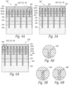
- FIGS 4A, 5A, 6A and 7 are schematic section views along the 3-3' line shown in FIG. 1B (i.e., parallel to the azimuthal direction) of transducer assemblies configured in accordance with examples not forming part of the invention ( FIGS 4A , 7 ) and embodiments ( FIGS 5A, 6A ) of the present invention.
- FIGS. 4B, 5B and 6B are enlarged views of corresponding portions FIGS. 4A, 5A and 6A .
- a transducer assembly 420 includes the first kerfs 342 and the second kerfs 344 having a groove 452 formed in the filler 348.
- the groove 452 has a width in the azimuthal direction substantially similar to widths of the first kerfs 342 and the second kerfs 344.
- the first kerfs 342 and the second kerfs 344 can have different groove depths.
- the groove 452 is filled with the same material (e.g., RTV) as the lens 222. In other examples, however, another material may be used.
- a transducer assembly 520 includes the first kerfs 342 and the second kerfs having a portion or groove 554 formed in the filler 348.
- the groove 554 has a smaller width in the azimuthal direction (e.g., 1/2 as wide, 1/4 as wide, 1/8 as wide) than the widths of the first kerfs 342 and the second kerfs 344.
- the first kerfs 342 and the second kerfs 344 can have differing groove depths.
- the groove 554 is filled with the same material (e.g., RTV) as the lens 222. In other embodiments, however, another material may be used.
- an ultrasound transducer assembly 620 includes the first kerfs 342 and the second kerfs having a portion or groove 656 formed in the filler 348.
- the groove 656 has a smaller width in the azimuthal direction (e.g., 1/2 as wide, 1/4 as wide, 1/8 as wide) than the widths of the first kerfs 342 and the second kerfs 344.
- the first kerfs 342 and the second kerfs 344 can have differing groove depths.
- the groove 656 is filled with the same material (e.g., RTV) as the lens 222. In other embodiments, however, another material may be used.
- an ultrasound transducer assembly 720 includes the first kerfs 342 and the second kerfs having a first filler material 752 (e.g., a polymer) above a second filler material 754 (e.g., a composite material comprising microballoons).
- first filler material 752 e.g., a polymer
- second filler material 754 e.g., a composite material comprising microballoons.
- grooves can be formed in the first filler material 752 as described above in reference to FIGS. 4A-6B .
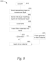
- FIG. 8 is a flow diagram of a process 800 of constructing an ultrasound transducer assembly. Although the process is not directly claimed, the resultant ultrasound transducer assembly may be in accordance with an embodiment of the invention.
- the process 800 begins.
- the process 800 bonds a lower surface of a transducer layer (e.g., the transducer layer 230 of FIG. 2 ) to an upper surface of the dematching layer using an adhesive (e.g., an epoxy, a polymer).
- an adhesive e.g., an epoxy, a polymer
- the process 800 bonds a first matching layer to the transducer layer and bonds one or more additional matching layer to the first matching layer.
- the process 800 can optionally bond a lower surface of a dematching layer (e.g., the dematching layer 234 of FIG. 2 ) to an upper surface of a backing layer (e.g., the backing layer 240 of FIG. 2 ) using an epoxy.
- the process 800 performs one or more cuts to form one or more kerfs (e.g., the first kerfs 342 or the second kerfs 344 of FIG. 3 ) in the transducer assembly.
- the process 800 inserts or otherwise fills at least a portion of the kerfs formed at block 850 with a filler material (e.g., a filler material comprising microballoons).
- a filler material e.g., a filler material comprising microballoons
- the process 800 determines whether one or more grooves is to be formed in the filler material inserted into the kerfs formed at block 860. If so, then the process 800 proceeds to block 875 and one or more kerfs are formed in the filler material inserted into the kerfs at block 860 (e.g., the grooves 452 of FIGS. 4A and 4B , the grooves 554 of FIGS. 5A and 5B and/or the grooves 656 of FIGS. 6A and 6B ).
- a lens material e.g., RTV or another suitable lens material
- the words “comprise,” “comprising,” and the like are to be construed in an inclusive sense, as opposed to an exclusive or exhaustive sense; that is to say, in the sense of "including, but not limited to.”
- the terms “connected,” “coupled,” or any variant thereof means any connection or coupling, either direct or indirect, between two or more elements; the coupling or connection between the elements can be physical, logical, or a combination thereof.
- the words “herein,” “above,” “below,” and words of similar import, when used in this application refer to this application as a whole and not to any particular portions of this application.
- transducer assemblies configured in accordance with the invention can include fewer than three matching layers, namely two matching layers. In other implementations, transducer assemblies can be configured in accordance with the disclosed technology without a dematching layer.
- the scope of the invention is defined by the appended claims.
Landscapes
- Health & Medical Sciences (AREA)
- Engineering & Computer Science (AREA)
- Life Sciences & Earth Sciences (AREA)
- Pathology (AREA)
- General Health & Medical Sciences (AREA)
- Physics & Mathematics (AREA)
- Mechanical Engineering (AREA)
- Manufacturing & Machinery (AREA)
- Heart & Thoracic Surgery (AREA)
- Veterinary Medicine (AREA)
- Radiology & Medical Imaging (AREA)
- Biomedical Technology (AREA)
- Biophysics (AREA)
- Medical Informatics (AREA)
- Molecular Biology (AREA)
- Surgery (AREA)
- Animal Behavior & Ethology (AREA)
- Nuclear Medicine, Radiotherapy & Molecular Imaging (AREA)
- Public Health (AREA)
- Gynecology & Obstetrics (AREA)
- Chemical & Material Sciences (AREA)
- Analytical Chemistry (AREA)
- Biochemistry (AREA)
- General Physics & Mathematics (AREA)
- Immunology (AREA)
- Transducers For Ultrasonic Waves (AREA)
- Ultra Sonic Daignosis Equipment (AREA)
Priority Applications (1)
| Application Number | Priority Date | Filing Date | Title |
|---|---|---|---|
| EP23163129.2A EP4219026A1 (en) | 2015-09-03 | 2016-09-02 | Ultrasound transducer assembly |
Applications Claiming Priority (2)
| Application Number | Priority Date | Filing Date | Title |
|---|---|---|---|
| US201562214185P | 2015-09-03 | 2015-09-03 | |
| PCT/US2016/050171 WO2017040979A1 (en) | 2015-09-03 | 2016-09-02 | Ultrasound transducer assembly |
Related Child Applications (2)
| Application Number | Title | Priority Date | Filing Date |
|---|---|---|---|
| EP23163129.2A Division-Into EP4219026A1 (en) | 2015-09-03 | 2016-09-02 | Ultrasound transducer assembly |
| EP23163129.2A Division EP4219026A1 (en) | 2015-09-03 | 2016-09-02 | Ultrasound transducer assembly |
Publications (3)
| Publication Number | Publication Date |
|---|---|
| EP3344147A1 EP3344147A1 (en) | 2018-07-11 |
| EP3344147A4 EP3344147A4 (en) | 2019-05-22 |
| EP3344147B1 true EP3344147B1 (en) | 2023-11-01 |
Family
ID=58188539
Family Applications (2)
| Application Number | Title | Priority Date | Filing Date |
|---|---|---|---|
| EP16843099.9A Active EP3344147B1 (en) | 2015-09-03 | 2016-09-02 | Ultrasound transducer assembly |
| EP23163129.2A Withdrawn EP4219026A1 (en) | 2015-09-03 | 2016-09-02 | Ultrasound transducer assembly |
Family Applications After (1)
| Application Number | Title | Priority Date | Filing Date |
|---|---|---|---|
| EP23163129.2A Withdrawn EP4219026A1 (en) | 2015-09-03 | 2016-09-02 | Ultrasound transducer assembly |
Country Status (6)
| Country | Link |
|---|---|
| US (3) | US10716542B2 (https=) |
| EP (2) | EP3344147B1 (https=) |
| JP (1) | JP6911013B2 (https=) |
| KR (1) | KR102633430B1 (https=) |
| CN (1) | CN107920797B (https=) |
| WO (1) | WO2017040979A1 (https=) |
Families Citing this family (19)
| Publication number | Priority date | Publication date | Assignee | Title |
|---|---|---|---|---|
| US9808830B2 (en) * | 2013-12-27 | 2017-11-07 | General Electric Company | Ultrasound transducer and ultrasound imaging system with a variable thickness dematching layer |
| KR20170090304A (ko) * | 2016-01-28 | 2017-08-07 | 삼성메디슨 주식회사 | 초음파 트랜스듀서 및 이를 포함하는 초음파 프로브 |
| USD831219S1 (en) * | 2017-07-31 | 2018-10-16 | Edan Instruments, Inc. | Transducer |
| US11678865B2 (en) | 2017-12-29 | 2023-06-20 | Fujifilm Sonosite, Inc. | High frequency ultrasound transducer |
| ES2997785T3 (en) * | 2018-07-31 | 2025-02-18 | Resonant Acoustics Int Inc | Ultrasonic transducer |
| CN112638548B (zh) * | 2018-08-31 | 2023-04-28 | 皇家飞利浦有限公司 | 非矩形换能器阵列以及相关联的设备、系统和方法 |
| CN109530196B (zh) * | 2018-11-28 | 2023-10-27 | 深圳先进技术研究院 | 换能器组件及其制备方法 |
| WO2020107283A1 (zh) * | 2018-11-28 | 2020-06-04 | 深圳先进技术研究院 | 换能器组件及其制备方法 |
| US11583259B2 (en) * | 2018-12-19 | 2023-02-21 | Fujifilm Sonosite, Inc. | Thermal conductive layer for transducer face temperature reduction |
| WO2020190593A1 (en) * | 2019-03-15 | 2020-09-24 | EchoNous, Inc. | Ultrasound transducer assembly having low viscosity kerf fill material |
| AU2020245521B2 (en) | 2019-03-25 | 2022-02-17 | Exo Imaging, Inc. | Handheld ultrasound imager |
| TWI869258B (zh) * | 2019-08-01 | 2025-01-01 | 加拿大商共振聲學國際股份有限公司 | 超音波傳感器 |
| TWI840394B (zh) * | 2019-08-01 | 2024-05-01 | 加拿大商共振聲學國際股份有限公司 | 超音波傳感器 |
| CA3158819A1 (en) * | 2019-11-18 | 2021-05-27 | Nicholas Chris CHAGGARES | Ultrasonic transducers, backing structures and related methods |
| JP2021136675A (ja) * | 2020-02-28 | 2021-09-13 | 学校法人早稲田大学 | 圧電素子 |
| CN113180727B (zh) * | 2021-03-29 | 2023-03-03 | 聚融医疗科技(杭州)有限公司 | 一种填缝材料可自由选择的超声换能器及其制备方法 |
| CN115414068B (zh) * | 2022-09-26 | 2025-07-18 | 武汉联影医疗科技有限公司 | 一种用于超声换能器的匹配层和制备方法 |
| US12558708B2 (en) * | 2021-12-23 | 2026-02-24 | Fujifilm Sonosite, Inc. | Array architecture and interconnection for transducers |
| CN116553469A (zh) * | 2022-03-24 | 2023-08-08 | 台湾积体电路制造股份有限公司 | 混合超声换能器系统 |
Family Cites Families (36)
| Publication number | Priority date | Publication date | Assignee | Title |
|---|---|---|---|---|
| JPS5315486U (https=) | 1976-07-21 | 1978-02-08 | ||
| JPS6029731B2 (ja) * | 1977-04-26 | 1985-07-12 | 旭化成株式会社 | 重縮合方法 |
| JPS5925500A (ja) | 1982-08-02 | 1984-02-09 | Matsushita Electric Ind Co Ltd | 超音波探触子の製造方法 |
| JPS6139700A (ja) * | 1984-07-30 | 1986-02-25 | Shimadzu Corp | 超音波探触子の製造方法 |
| JPS6139700U (ja) | 1984-08-15 | 1986-03-13 | 三菱重工業株式会社 | 機関室給気装置 |
| DE3650004T2 (de) | 1985-05-20 | 1995-02-23 | Matsushita Electric Ind Co Ltd | Ultraschallsonde. |
| JP2794720B2 (ja) | 1988-08-23 | 1998-09-10 | 松下電器産業株式会社 | 複合圧電振動子 |
| US5311095A (en) * | 1992-05-14 | 1994-05-10 | Duke University | Ultrasonic transducer array |
| US5553035A (en) * | 1993-06-15 | 1996-09-03 | Hewlett-Packard Company | Method of forming integral transducer and impedance matching layers |
| US5648942A (en) * | 1995-10-13 | 1997-07-15 | Advanced Technology Laboratories, Inc. | Acoustic backing with integral conductors for an ultrasonic transducer |
| JP3673035B2 (ja) * | 1996-10-25 | 2005-07-20 | 株式会社東芝 | 超音波トランスジューサ |
| US6359375B1 (en) * | 1998-05-06 | 2002-03-19 | Siemens Medical Solutions Usa, Inc. | Method to build a high bandwidth, low crosstalk, low EM noise transducer |
| JP2003175036A (ja) | 2001-12-11 | 2003-06-24 | Aloka Co Ltd | 超音波探触子及び超音波診断装置 |
| JP3908595B2 (ja) | 2002-05-17 | 2007-04-25 | アロカ株式会社 | 超音波探触子 |
| US20040190377A1 (en) * | 2003-03-06 | 2004-09-30 | Lewandowski Robert Stephen | Method and means for isolating elements of a sensor array |
| US7368852B2 (en) | 2003-08-22 | 2008-05-06 | Siemens Medical Solutions Usa, Inc. | Electrically conductive matching layers and methods |
| US7285897B2 (en) * | 2003-12-31 | 2007-10-23 | General Electric Company | Curved micromachined ultrasonic transducer arrays and related methods of manufacture |
| US20070222339A1 (en) * | 2004-04-20 | 2007-09-27 | Mark Lukacs | Arrayed ultrasonic transducer |
| JP2005340903A (ja) * | 2004-05-24 | 2005-12-08 | Olympus Corp | 超音波トランスデューサとその製造方法 |
| US20060028099A1 (en) | 2004-08-05 | 2006-02-09 | Frey Gregg W | Composite acoustic matching layer |
| JP4933392B2 (ja) * | 2007-04-02 | 2012-05-16 | 富士フイルム株式会社 | 超音波探触子及びその製造方法 |
| JP5002402B2 (ja) * | 2007-10-03 | 2012-08-15 | 株式会社東芝 | 超音波探触子及び超音波診断装置 |
| US8378557B2 (en) * | 2010-07-09 | 2013-02-19 | General Electric Company | Thermal transfer and acoustic matching layers for ultrasound transducer |
| JP5643667B2 (ja) | 2011-01-28 | 2014-12-17 | 株式会社東芝 | 超音波トランスデューサ、超音波プローブおよび超音波トランスデューサの製造方法 |
| JP5468564B2 (ja) * | 2011-03-30 | 2014-04-09 | 富士フイルム株式会社 | 超音波探触子および超音波診断装置 |
| JP6548201B2 (ja) * | 2011-09-16 | 2019-07-24 | ゼネラル・エレクトリック・カンパニイ | 超音波変換器のための熱移動および音響整合層 |
| KR101269459B1 (ko) | 2011-12-13 | 2013-05-30 | 삼성전자주식회사 | 초음파 프로브 및 그 제조방법 |
| KR101477544B1 (ko) | 2012-01-02 | 2014-12-31 | 삼성전자주식회사 | 초음파 트랜스듀서, 초음파 프로브, 및 초음파 진단장치 |
| JP5315486B1 (ja) * | 2012-01-30 | 2013-10-16 | オリンパスメディカルシステムズ株式会社 | 超音波振動子アレイ、超音波振動子アレイの製造方法、及び超音波内視鏡 |
| JP6029731B2 (ja) | 2012-02-07 | 2016-11-24 | 富士フイルム株式会社 | 超音波探触子 |
| JP5924298B2 (ja) * | 2013-03-19 | 2016-05-25 | コニカミノルタ株式会社 | 超音波探触子及び超音波画像診断装置 |
| JP2014188009A (ja) | 2013-03-26 | 2014-10-06 | Konica Minolta Inc | 超音波探触子、超音波画像診断装置及び超音波探触子の製造方法 |
| JP6214333B2 (ja) * | 2013-10-23 | 2017-10-18 | 三菱鉛筆株式会社 | 音響整合層とその製造方法 |
| JP5665948B1 (ja) * | 2013-11-14 | 2015-02-04 | 株式会社フジクラ | 携帯型電子機器の冷却構造 |
| JP6139700B2 (ja) | 2013-12-02 | 2017-05-31 | 株式会社東芝 | 漏水抑制装置、漏水抑制システム、および漏水抑制プログラム |
| JP6641723B2 (ja) | 2015-05-08 | 2020-02-05 | コニカミノルタ株式会社 | 超音波振動子およびその製造方法、超音波探触子ならびに超音波撮像装置 |
-
2016
- 2016-09-02 CN CN201680049560.3A patent/CN107920797B/zh active Active
- 2016-09-02 KR KR1020187005215A patent/KR102633430B1/ko active Active
- 2016-09-02 JP JP2018511677A patent/JP6911013B2/ja active Active
- 2016-09-02 WO PCT/US2016/050171 patent/WO2017040979A1/en not_active Ceased
- 2016-09-02 EP EP16843099.9A patent/EP3344147B1/en active Active
- 2016-09-02 US US15/256,029 patent/US10716542B2/en active Active
- 2016-09-02 EP EP23163129.2A patent/EP4219026A1/en not_active Withdrawn
-
2020
- 2020-07-20 US US16/933,822 patent/US11890140B2/en active Active
-
2024
- 2024-01-26 US US18/424,618 patent/US20240164754A1/en active Pending
Also Published As
| Publication number | Publication date |
|---|---|
| JP2018532307A (ja) | 2018-11-01 |
| US20200345328A1 (en) | 2020-11-05 |
| CN107920797B (zh) | 2021-02-12 |
| US20240164754A1 (en) | 2024-05-23 |
| KR20180038467A (ko) | 2018-04-16 |
| KR102633430B1 (ko) | 2024-02-02 |
| US10716542B2 (en) | 2020-07-21 |
| EP3344147A1 (en) | 2018-07-11 |
| WO2017040979A1 (en) | 2017-03-09 |
| US11890140B2 (en) | 2024-02-06 |
| US20170065253A1 (en) | 2017-03-09 |
| CN107920797A (zh) | 2018-04-17 |
| EP3344147A4 (en) | 2019-05-22 |
| JP6911013B2 (ja) | 2021-07-28 |
| EP4219026A1 (en) | 2023-08-02 |
Similar Documents
| Publication | Publication Date | Title |
|---|---|---|
| EP3344147B1 (en) | Ultrasound transducer assembly | |
| US8207652B2 (en) | Ultrasound transducer with improved acoustic performance | |
| US11800806B2 (en) | Method for manufacturing a multi-cell transducer | |
| US8378557B2 (en) | Thermal transfer and acoustic matching layers for ultrasound transducer | |
| US9799818B2 (en) | Ultrasound probe with heat collecting portion | |
| JP2014183589A (ja) | 微細加工超音波トランスデューサのための音響レンズ | |
| US11691177B2 (en) | Ultrasound probe with acoustic amplifier | |
| US11998397B2 (en) | Thermal conductive layer for transducer face temperature reduction | |
| KR20160096935A (ko) | 음향특성 및 열특성을 향상시키는 초음파 트랜스듀서 | |
| HK40074991B (en) | Multi-cell transducer | |
| HK40074991A (en) | Multi-cell transducer | |
| HK1231437B (en) | Multi-cell transducer |
Legal Events
| Date | Code | Title | Description |
|---|---|---|---|
| STAA | Information on the status of an ep patent application or granted ep patent |
Free format text: STATUS: THE INTERNATIONAL PUBLICATION HAS BEEN MADE |
|
| PUAI | Public reference made under article 153(3) epc to a published international application that has entered the european phase |
Free format text: ORIGINAL CODE: 0009012 |
|
| STAA | Information on the status of an ep patent application or granted ep patent |
Free format text: STATUS: REQUEST FOR EXAMINATION WAS MADE |
|
| 17P | Request for examination filed |
Effective date: 20180322 |
|
| AK | Designated contracting states |
Kind code of ref document: A1 Designated state(s): AL AT BE BG CH CY CZ DE DK EE ES FI FR GB GR HR HU IE IS IT LI LT LU LV MC MK MT NL NO PL PT RO RS SE SI SK SM TR |
|
| AX | Request for extension of the european patent |
Extension state: BA ME |
|
| DAV | Request for validation of the european patent (deleted) | ||
| DAX | Request for extension of the european patent (deleted) | ||
| A4 | Supplementary search report drawn up and despatched |
Effective date: 20190424 |
|
| RIC1 | Information provided on ipc code assigned before grant |
Ipc: H01L 41/09 20060101ALI20190416BHEP Ipc: A61B 8/00 20060101ALI20190416BHEP Ipc: H01L 41/312 20130101ALI20190416BHEP Ipc: H01L 41/338 20130101ALI20190416BHEP Ipc: B06B 1/06 20060101AFI20190416BHEP |
|
| STAA | Information on the status of an ep patent application or granted ep patent |
Free format text: STATUS: EXAMINATION IS IN PROGRESS |
|
| 17Q | First examination report despatched |
Effective date: 20210609 |
|
| GRAP | Despatch of communication of intention to grant a patent |
Free format text: ORIGINAL CODE: EPIDOSNIGR1 |
|
| STAA | Information on the status of an ep patent application or granted ep patent |
Free format text: STATUS: GRANT OF PATENT IS INTENDED |
|
| INTG | Intention to grant announced |
Effective date: 20221025 |
|
| GRAJ | Information related to disapproval of communication of intention to grant by the applicant or resumption of examination proceedings by the epo deleted |
Free format text: ORIGINAL CODE: EPIDOSDIGR1 |
|
| STAA | Information on the status of an ep patent application or granted ep patent |
Free format text: STATUS: EXAMINATION IS IN PROGRESS |
|
| REG | Reference to a national code |
Ref country code: DE Free format text: PREVIOUS MAIN CLASS: A61B0008000000 Ref legal event code: R079 Ref document number: 602016083893 Country of ref document: DE Ipc: B06B0001060000 |
|
| GRAP | Despatch of communication of intention to grant a patent |
Free format text: ORIGINAL CODE: EPIDOSNIGR1 |
|
| STAA | Information on the status of an ep patent application or granted ep patent |
Free format text: STATUS: GRANT OF PATENT IS INTENDED |
|
| INTC | Intention to grant announced (deleted) | ||
| RIC1 | Information provided on ipc code assigned before grant |
Ipc: H10N 30/20 20230101ALI20230309BHEP Ipc: H10N 30/072 20230101ALI20230309BHEP Ipc: H10N 30/088 20230101ALI20230309BHEP Ipc: A61B 8/00 20060101ALI20230309BHEP Ipc: B06B 1/06 20060101AFI20230309BHEP |
|
| INTG | Intention to grant announced |
Effective date: 20230321 |
|
| GRAS | Grant fee paid |
Free format text: ORIGINAL CODE: EPIDOSNIGR3 |
|
| GRAA | (expected) grant |
Free format text: ORIGINAL CODE: 0009210 |
|
| STAA | Information on the status of an ep patent application or granted ep patent |
Free format text: STATUS: THE PATENT HAS BEEN GRANTED |
|
| AK | Designated contracting states |
Kind code of ref document: B1 Designated state(s): AL AT BE BG CH CY CZ DE DK EE ES FI FR GB GR HR HU IE IS IT LI LT LU LV MC MK MT NL NO PL PT RO RS SE SI SK SM TR |
|
| REG | Reference to a national code |
Ref country code: GB Ref legal event code: FG4D |
|
| REG | Reference to a national code |
Ref country code: CH Ref legal event code: EP |
|
| REG | Reference to a national code |
Ref country code: DE Ref legal event code: R096 Ref document number: 602016083893 Country of ref document: DE |
|
| REG | Reference to a national code |
Ref country code: IE Ref legal event code: FG4D Ref country code: NL Ref legal event code: FP |
|
| REG | Reference to a national code |
Ref country code: LT Ref legal event code: MG9D |
|
| PG25 | Lapsed in a contracting state [announced via postgrant information from national office to epo] |
Ref country code: GR Free format text: LAPSE BECAUSE OF FAILURE TO SUBMIT A TRANSLATION OF THE DESCRIPTION OR TO PAY THE FEE WITHIN THE PRESCRIBED TIME-LIMIT Effective date: 20240202 |
|
| PG25 | Lapsed in a contracting state [announced via postgrant information from national office to epo] |
Ref country code: IS Free format text: LAPSE BECAUSE OF FAILURE TO SUBMIT A TRANSLATION OF THE DESCRIPTION OR TO PAY THE FEE WITHIN THE PRESCRIBED TIME-LIMIT Effective date: 20240301 |
|
| PG25 | Lapsed in a contracting state [announced via postgrant information from national office to epo] |
Ref country code: LT Free format text: LAPSE BECAUSE OF FAILURE TO SUBMIT A TRANSLATION OF THE DESCRIPTION OR TO PAY THE FEE WITHIN THE PRESCRIBED TIME-LIMIT Effective date: 20231101 |
|
| REG | Reference to a national code |
Ref country code: AT Ref legal event code: MK05 Ref document number: 1626606 Country of ref document: AT Kind code of ref document: T Effective date: 20231101 |
|
| PG25 | Lapsed in a contracting state [announced via postgrant information from national office to epo] |
Ref country code: AT Free format text: LAPSE BECAUSE OF FAILURE TO SUBMIT A TRANSLATION OF THE DESCRIPTION OR TO PAY THE FEE WITHIN THE PRESCRIBED TIME-LIMIT Effective date: 20231101 |
|
| PG25 | Lapsed in a contracting state [announced via postgrant information from national office to epo] |
Ref country code: ES Free format text: LAPSE BECAUSE OF FAILURE TO SUBMIT A TRANSLATION OF THE DESCRIPTION OR TO PAY THE FEE WITHIN THE PRESCRIBED TIME-LIMIT Effective date: 20231101 |
|
| PG25 | Lapsed in a contracting state [announced via postgrant information from national office to epo] |
Ref country code: LT Free format text: LAPSE BECAUSE OF FAILURE TO SUBMIT A TRANSLATION OF THE DESCRIPTION OR TO PAY THE FEE WITHIN THE PRESCRIBED TIME-LIMIT Effective date: 20231101 Ref country code: IS Free format text: LAPSE BECAUSE OF FAILURE TO SUBMIT A TRANSLATION OF THE DESCRIPTION OR TO PAY THE FEE WITHIN THE PRESCRIBED TIME-LIMIT Effective date: 20240301 Ref country code: GR Free format text: LAPSE BECAUSE OF FAILURE TO SUBMIT A TRANSLATION OF THE DESCRIPTION OR TO PAY THE FEE WITHIN THE PRESCRIBED TIME-LIMIT Effective date: 20240202 Ref country code: ES Free format text: LAPSE BECAUSE OF FAILURE TO SUBMIT A TRANSLATION OF THE DESCRIPTION OR TO PAY THE FEE WITHIN THE PRESCRIBED TIME-LIMIT Effective date: 20231101 Ref country code: BG Free format text: LAPSE BECAUSE OF FAILURE TO SUBMIT A TRANSLATION OF THE DESCRIPTION OR TO PAY THE FEE WITHIN THE PRESCRIBED TIME-LIMIT Effective date: 20240201 Ref country code: AT Free format text: LAPSE BECAUSE OF FAILURE TO SUBMIT A TRANSLATION OF THE DESCRIPTION OR TO PAY THE FEE WITHIN THE PRESCRIBED TIME-LIMIT Effective date: 20231101 Ref country code: PT Free format text: LAPSE BECAUSE OF FAILURE TO SUBMIT A TRANSLATION OF THE DESCRIPTION OR TO PAY THE FEE WITHIN THE PRESCRIBED TIME-LIMIT Effective date: 20240301 |
|
| PG25 | Lapsed in a contracting state [announced via postgrant information from national office to epo] |
Ref country code: SE Free format text: LAPSE BECAUSE OF FAILURE TO SUBMIT A TRANSLATION OF THE DESCRIPTION OR TO PAY THE FEE WITHIN THE PRESCRIBED TIME-LIMIT Effective date: 20231101 Ref country code: RS Free format text: LAPSE BECAUSE OF FAILURE TO SUBMIT A TRANSLATION OF THE DESCRIPTION OR TO PAY THE FEE WITHIN THE PRESCRIBED TIME-LIMIT Effective date: 20231101 Ref country code: PL Free format text: LAPSE BECAUSE OF FAILURE TO SUBMIT A TRANSLATION OF THE DESCRIPTION OR TO PAY THE FEE WITHIN THE PRESCRIBED TIME-LIMIT Effective date: 20231101 Ref country code: NO Free format text: LAPSE BECAUSE OF FAILURE TO SUBMIT A TRANSLATION OF THE DESCRIPTION OR TO PAY THE FEE WITHIN THE PRESCRIBED TIME-LIMIT Effective date: 20240201 Ref country code: LV Free format text: LAPSE BECAUSE OF FAILURE TO SUBMIT A TRANSLATION OF THE DESCRIPTION OR TO PAY THE FEE WITHIN THE PRESCRIBED TIME-LIMIT Effective date: 20231101 Ref country code: HR Free format text: LAPSE BECAUSE OF FAILURE TO SUBMIT A TRANSLATION OF THE DESCRIPTION OR TO PAY THE FEE WITHIN THE PRESCRIBED TIME-LIMIT Effective date: 20231101 |
|
| PG25 | Lapsed in a contracting state [announced via postgrant information from national office to epo] |
Ref country code: DK Free format text: LAPSE BECAUSE OF FAILURE TO SUBMIT A TRANSLATION OF THE DESCRIPTION OR TO PAY THE FEE WITHIN THE PRESCRIBED TIME-LIMIT Effective date: 20231101 |
|
| PG25 | Lapsed in a contracting state [announced via postgrant information from national office to epo] |
Ref country code: CZ Free format text: LAPSE BECAUSE OF FAILURE TO SUBMIT A TRANSLATION OF THE DESCRIPTION OR TO PAY THE FEE WITHIN THE PRESCRIBED TIME-LIMIT Effective date: 20231101 |
|
| PG25 | Lapsed in a contracting state [announced via postgrant information from national office to epo] |
Ref country code: SK Free format text: LAPSE BECAUSE OF FAILURE TO SUBMIT A TRANSLATION OF THE DESCRIPTION OR TO PAY THE FEE WITHIN THE PRESCRIBED TIME-LIMIT Effective date: 20231101 |
|
| PG25 | Lapsed in a contracting state [announced via postgrant information from national office to epo] |
Ref country code: SM Free format text: LAPSE BECAUSE OF FAILURE TO SUBMIT A TRANSLATION OF THE DESCRIPTION OR TO PAY THE FEE WITHIN THE PRESCRIBED TIME-LIMIT Effective date: 20231101 Ref country code: SK Free format text: LAPSE BECAUSE OF FAILURE TO SUBMIT A TRANSLATION OF THE DESCRIPTION OR TO PAY THE FEE WITHIN THE PRESCRIBED TIME-LIMIT Effective date: 20231101 Ref country code: RO Free format text: LAPSE BECAUSE OF FAILURE TO SUBMIT A TRANSLATION OF THE DESCRIPTION OR TO PAY THE FEE WITHIN THE PRESCRIBED TIME-LIMIT Effective date: 20231101 Ref country code: IT Free format text: LAPSE BECAUSE OF FAILURE TO SUBMIT A TRANSLATION OF THE DESCRIPTION OR TO PAY THE FEE WITHIN THE PRESCRIBED TIME-LIMIT Effective date: 20231101 Ref country code: EE Free format text: LAPSE BECAUSE OF FAILURE TO SUBMIT A TRANSLATION OF THE DESCRIPTION OR TO PAY THE FEE WITHIN THE PRESCRIBED TIME-LIMIT Effective date: 20231101 Ref country code: DK Free format text: LAPSE BECAUSE OF FAILURE TO SUBMIT A TRANSLATION OF THE DESCRIPTION OR TO PAY THE FEE WITHIN THE PRESCRIBED TIME-LIMIT Effective date: 20231101 Ref country code: CZ Free format text: LAPSE BECAUSE OF FAILURE TO SUBMIT A TRANSLATION OF THE DESCRIPTION OR TO PAY THE FEE WITHIN THE PRESCRIBED TIME-LIMIT Effective date: 20231101 |
|
| REG | Reference to a national code |
Ref country code: DE Ref legal event code: R097 Ref document number: 602016083893 Country of ref document: DE |
|
| PLBE | No opposition filed within time limit |
Free format text: ORIGINAL CODE: 0009261 |
|
| STAA | Information on the status of an ep patent application or granted ep patent |
Free format text: STATUS: NO OPPOSITION FILED WITHIN TIME LIMIT |
|
| 26N | No opposition filed |
Effective date: 20240802 |
|
| PG25 | Lapsed in a contracting state [announced via postgrant information from national office to epo] |
Ref country code: SI Free format text: LAPSE BECAUSE OF FAILURE TO SUBMIT A TRANSLATION OF THE DESCRIPTION OR TO PAY THE FEE WITHIN THE PRESCRIBED TIME-LIMIT Effective date: 20231101 |
|
| PG25 | Lapsed in a contracting state [announced via postgrant information from national office to epo] |
Ref country code: SI Free format text: LAPSE BECAUSE OF FAILURE TO SUBMIT A TRANSLATION OF THE DESCRIPTION OR TO PAY THE FEE WITHIN THE PRESCRIBED TIME-LIMIT Effective date: 20231101 |
|
| PG25 | Lapsed in a contracting state [announced via postgrant information from national office to epo] |
Ref country code: MC Free format text: LAPSE BECAUSE OF FAILURE TO SUBMIT A TRANSLATION OF THE DESCRIPTION OR TO PAY THE FEE WITHIN THE PRESCRIBED TIME-LIMIT Effective date: 20231101 |
|
| REG | Reference to a national code |
Ref country code: CH Ref legal event code: PL |
|
| PG25 | Lapsed in a contracting state [announced via postgrant information from national office to epo] |
Ref country code: LU Free format text: LAPSE BECAUSE OF NON-PAYMENT OF DUE FEES Effective date: 20240902 |
|
| REG | Reference to a national code |
Ref country code: BE Ref legal event code: MM Effective date: 20240930 |
|
| PG25 | Lapsed in a contracting state [announced via postgrant information from national office to epo] |
Ref country code: BE Free format text: LAPSE BECAUSE OF NON-PAYMENT OF DUE FEES Effective date: 20240930 |
|
| PG25 | Lapsed in a contracting state [announced via postgrant information from national office to epo] |
Ref country code: CH Free format text: LAPSE BECAUSE OF NON-PAYMENT OF DUE FEES Effective date: 20240930 |
|
| PG25 | Lapsed in a contracting state [announced via postgrant information from national office to epo] |
Ref country code: IE Free format text: LAPSE BECAUSE OF NON-PAYMENT OF DUE FEES Effective date: 20240902 |
|
| PGFP | Annual fee paid to national office [announced via postgrant information from national office to epo] |
Ref country code: NL Payment date: 20250814 Year of fee payment: 10 |
|
| PG25 | Lapsed in a contracting state [announced via postgrant information from national office to epo] |
Ref country code: FI Free format text: LAPSE BECAUSE OF FAILURE TO SUBMIT A TRANSLATION OF THE DESCRIPTION OR TO PAY THE FEE WITHIN THE PRESCRIBED TIME-LIMIT Effective date: 20231101 |
|
| PGFP | Annual fee paid to national office [announced via postgrant information from national office to epo] |
Ref country code: DE Payment date: 20250730 Year of fee payment: 10 |
|
| PGFP | Annual fee paid to national office [announced via postgrant information from national office to epo] |
Ref country code: GB Payment date: 20250731 Year of fee payment: 10 |
|
| PGFP | Annual fee paid to national office [announced via postgrant information from national office to epo] |
Ref country code: FR Payment date: 20250808 Year of fee payment: 10 |
|
| PG25 | Lapsed in a contracting state [announced via postgrant information from national office to epo] |
Ref country code: CY Free format text: LAPSE BECAUSE OF FAILURE TO SUBMIT A TRANSLATION OF THE DESCRIPTION OR TO PAY THE FEE WITHIN THE PRESCRIBED TIME-LIMIT; INVALID AB INITIO Effective date: 20160902 |
|
| PG25 | Lapsed in a contracting state [announced via postgrant information from national office to epo] |
Ref country code: HU Free format text: LAPSE BECAUSE OF FAILURE TO SUBMIT A TRANSLATION OF THE DESCRIPTION OR TO PAY THE FEE WITHIN THE PRESCRIBED TIME-LIMIT; INVALID AB INITIO Effective date: 20160902 |