EP3344147B1 - Ultrasound transducer assembly - Google Patents
Ultrasound transducer assembly Download PDFInfo
- Publication number
- EP3344147B1 EP3344147B1 EP16843099.9A EP16843099A EP3344147B1 EP 3344147 B1 EP3344147 B1 EP 3344147B1 EP 16843099 A EP16843099 A EP 16843099A EP 3344147 B1 EP3344147 B1 EP 3344147B1
- Authority
- EP
- European Patent Office
- Prior art keywords
- kerfs
- transducer assembly
- layer
- transducer
- width
- Prior art date
- Legal status (The legal status is an assumption and is not a legal conclusion. Google has not performed a legal analysis and makes no representation as to the accuracy of the status listed.)
- Active
Links
- 238000002604 ultrasonography Methods 0.000 title claims description 42
- 239000000463 material Substances 0.000 claims description 45
- 239000000945 filler Substances 0.000 claims description 34
- 239000002131 composite material Substances 0.000 claims description 9
- 230000007423 decrease Effects 0.000 claims description 2
- 238000000034 method Methods 0.000 description 16
- 238000005516 engineering process Methods 0.000 description 15
- 230000008569 process Effects 0.000 description 12
- 230000000712 assembly Effects 0.000 description 10
- 238000000429 assembly Methods 0.000 description 10
- 239000004593 Epoxy Substances 0.000 description 7
- 239000000523 sample Substances 0.000 description 7
- 229920000642 polymer Polymers 0.000 description 5
- 238000012285 ultrasound imaging Methods 0.000 description 4
- 229910052451 lead zirconate titanate Inorganic materials 0.000 description 3
- 239000004005 microsphere Substances 0.000 description 3
- 230000008901 benefit Effects 0.000 description 2
- PMHQVHHXPFUNSP-UHFFFAOYSA-M copper(1+);methylsulfanylmethane;bromide Chemical compound Br[Cu].CSC PMHQVHHXPFUNSP-UHFFFAOYSA-M 0.000 description 2
- 230000008878 coupling Effects 0.000 description 2
- 238000010168 coupling process Methods 0.000 description 2
- 238000005859 coupling reaction Methods 0.000 description 2
- 238000010586 diagram Methods 0.000 description 2
- 238000002592 echocardiography Methods 0.000 description 2
- 238000003384 imaging method Methods 0.000 description 2
- 238000004519 manufacturing process Methods 0.000 description 2
- OKTJSMMVPCPJKN-UHFFFAOYSA-N Carbon Chemical compound [C] OKTJSMMVPCPJKN-UHFFFAOYSA-N 0.000 description 1
- 239000004215 Carbon black (E152) Substances 0.000 description 1
- RYGMFSIKBFXOCR-UHFFFAOYSA-N Copper Chemical compound [Cu] RYGMFSIKBFXOCR-UHFFFAOYSA-N 0.000 description 1
- 239000012814 acoustic material Substances 0.000 description 1
- 239000000853 adhesive Substances 0.000 description 1
- 230000001070 adhesive effect Effects 0.000 description 1
- 239000004964 aerogel Substances 0.000 description 1
- 230000004075 alteration Effects 0.000 description 1
- 229910010293 ceramic material Inorganic materials 0.000 description 1
- 238000006243 chemical reaction Methods 0.000 description 1
- 229910052802 copper Inorganic materials 0.000 description 1
- 239000010949 copper Substances 0.000 description 1
- 239000006260 foam Substances 0.000 description 1
- 239000011521 glass Substances 0.000 description 1
- 229910002804 graphite Inorganic materials 0.000 description 1
- 239000010439 graphite Substances 0.000 description 1
- 229930195733 hydrocarbon Natural products 0.000 description 1
- 150000002430 hydrocarbons Chemical class 0.000 description 1
- 230000008676 import Effects 0.000 description 1
- HFGPZNIAWCZYJU-UHFFFAOYSA-N lead zirconate titanate Chemical compound [O-2].[O-2].[O-2].[O-2].[O-2].[Ti+4].[Zr+4].[Pb+2] HFGPZNIAWCZYJU-UHFFFAOYSA-N 0.000 description 1
- 239000002245 particle Substances 0.000 description 1
- 230000035515 penetration Effects 0.000 description 1
- 229910021420 polycrystalline silicon Inorganic materials 0.000 description 1
- 229920001296 polysiloxane Polymers 0.000 description 1
- 230000001902 propagating effect Effects 0.000 description 1
- 230000004044 response Effects 0.000 description 1
- 230000035945 sensitivity Effects 0.000 description 1
- 239000002002 slurry Substances 0.000 description 1
- 239000007787 solid Substances 0.000 description 1
- 238000006467 substitution reaction Methods 0.000 description 1
- 239000012780 transparent material Substances 0.000 description 1
- WFKWXMTUELFFGS-UHFFFAOYSA-N tungsten Chemical compound [W] WFKWXMTUELFFGS-UHFFFAOYSA-N 0.000 description 1
- 229910052721 tungsten Inorganic materials 0.000 description 1
- 239000010937 tungsten Substances 0.000 description 1
- UONOETXJSWQNOL-UHFFFAOYSA-N tungsten carbide Chemical compound [W+]#[C-] UONOETXJSWQNOL-UHFFFAOYSA-N 0.000 description 1
- 238000004073 vulcanization Methods 0.000 description 1
Images


Classifications
-
- A—HUMAN NECESSITIES
- A61—MEDICAL OR VETERINARY SCIENCE; HYGIENE
- A61B—DIAGNOSIS; SURGERY; IDENTIFICATION
- A61B8/00—Diagnosis using ultrasonic, sonic or infrasonic waves
- A61B8/44—Constructional features of the ultrasonic, sonic or infrasonic diagnostic device
- A61B8/4483—Constructional features of the ultrasonic, sonic or infrasonic diagnostic device characterised by features of the ultrasound transducer
- A61B8/4488—Constructional features of the ultrasonic, sonic or infrasonic diagnostic device characterised by features of the ultrasound transducer the transducer being a phased array
-
- A—HUMAN NECESSITIES
- A61—MEDICAL OR VETERINARY SCIENCE; HYGIENE
- A61B—DIAGNOSIS; SURGERY; IDENTIFICATION
- A61B8/00—Diagnosis using ultrasonic, sonic or infrasonic waves
- A61B8/44—Constructional features of the ultrasonic, sonic or infrasonic diagnostic device
- A61B8/4483—Constructional features of the ultrasonic, sonic or infrasonic diagnostic device characterised by features of the ultrasound transducer
- A61B8/4494—Constructional features of the ultrasonic, sonic or infrasonic diagnostic device characterised by features of the ultrasound transducer characterised by the arrangement of the transducer elements
-
- B—PERFORMING OPERATIONS; TRANSPORTING
- B06—GENERATING OR TRANSMITTING MECHANICAL VIBRATIONS IN GENERAL
- B06B—METHODS OR APPARATUS FOR GENERATING OR TRANSMITTING MECHANICAL VIBRATIONS OF INFRASONIC, SONIC, OR ULTRASONIC FREQUENCY, e.g. FOR PERFORMING MECHANICAL WORK IN GENERAL
- B06B1/00—Methods or apparatus for generating mechanical vibrations of infrasonic, sonic, or ultrasonic frequency
- B06B1/02—Methods or apparatus for generating mechanical vibrations of infrasonic, sonic, or ultrasonic frequency making use of electrical energy
- B06B1/06—Methods or apparatus for generating mechanical vibrations of infrasonic, sonic, or ultrasonic frequency making use of electrical energy operating with piezoelectric effect or with electrostriction
- B06B1/0607—Methods or apparatus for generating mechanical vibrations of infrasonic, sonic, or ultrasonic frequency making use of electrical energy operating with piezoelectric effect or with electrostriction using multiple elements
- B06B1/0622—Methods or apparatus for generating mechanical vibrations of infrasonic, sonic, or ultrasonic frequency making use of electrical energy operating with piezoelectric effect or with electrostriction using multiple elements on one surface
-
- B—PERFORMING OPERATIONS; TRANSPORTING
- B06—GENERATING OR TRANSMITTING MECHANICAL VIBRATIONS IN GENERAL
- B06B—METHODS OR APPARATUS FOR GENERATING OR TRANSMITTING MECHANICAL VIBRATIONS OF INFRASONIC, SONIC, OR ULTRASONIC FREQUENCY, e.g. FOR PERFORMING MECHANICAL WORK IN GENERAL
- B06B1/00—Methods or apparatus for generating mechanical vibrations of infrasonic, sonic, or ultrasonic frequency
- B06B1/02—Methods or apparatus for generating mechanical vibrations of infrasonic, sonic, or ultrasonic frequency making use of electrical energy
- B06B1/06—Methods or apparatus for generating mechanical vibrations of infrasonic, sonic, or ultrasonic frequency making use of electrical energy operating with piezoelectric effect or with electrostriction
- B06B1/0644—Methods or apparatus for generating mechanical vibrations of infrasonic, sonic, or ultrasonic frequency making use of electrical energy operating with piezoelectric effect or with electrostriction using a single piezoelectric element
- B06B1/0662—Methods or apparatus for generating mechanical vibrations of infrasonic, sonic, or ultrasonic frequency making use of electrical energy operating with piezoelectric effect or with electrostriction using a single piezoelectric element with an electrode on the sensitive surface
- B06B1/067—Methods or apparatus for generating mechanical vibrations of infrasonic, sonic, or ultrasonic frequency making use of electrical energy operating with piezoelectric effect or with electrostriction using a single piezoelectric element with an electrode on the sensitive surface which is used as, or combined with, an impedance matching layer
-
- G—PHYSICS
- G01—MEASURING; TESTING
- G01N—INVESTIGATING OR ANALYSING MATERIALS BY DETERMINING THEIR CHEMICAL OR PHYSICAL PROPERTIES
- G01N29/00—Investigating or analysing materials by the use of ultrasonic, sonic or infrasonic waves; Visualisation of the interior of objects by transmitting ultrasonic or sonic waves through the object
- G01N29/22—Details, e.g. general constructional or apparatus details
- G01N29/24—Probes
- G01N29/2406—Electrostatic or capacitive probes, e.g. electret or cMUT-probes
-
- G—PHYSICS
- G01—MEASURING; TESTING
- G01N—INVESTIGATING OR ANALYSING MATERIALS BY DETERMINING THEIR CHEMICAL OR PHYSICAL PROPERTIES
- G01N29/00—Investigating or analysing materials by the use of ultrasonic, sonic or infrasonic waves; Visualisation of the interior of objects by transmitting ultrasonic or sonic waves through the object
- G01N29/22—Details, e.g. general constructional or apparatus details
- G01N29/24—Probes
- G01N29/2437—Piezoelectric probes
-
- H—ELECTRICITY
- H10—SEMICONDUCTOR DEVICES; ELECTRIC SOLID-STATE DEVICES NOT OTHERWISE PROVIDED FOR
- H10N—ELECTRIC SOLID-STATE DEVICES NOT OTHERWISE PROVIDED FOR
- H10N30/00—Piezoelectric or electrostrictive devices
- H10N30/01—Manufacture or treatment
- H10N30/07—Forming of piezoelectric or electrostrictive parts or bodies on an electrical element or another base
- H10N30/072—Forming of piezoelectric or electrostrictive parts or bodies on an electrical element or another base by laminating or bonding of piezoelectric or electrostrictive bodies
-
- H—ELECTRICITY
- H10—SEMICONDUCTOR DEVICES; ELECTRIC SOLID-STATE DEVICES NOT OTHERWISE PROVIDED FOR
- H10N—ELECTRIC SOLID-STATE DEVICES NOT OTHERWISE PROVIDED FOR
- H10N30/00—Piezoelectric or electrostrictive devices
- H10N30/01—Manufacture or treatment
- H10N30/08—Shaping or machining of piezoelectric or electrostrictive bodies
- H10N30/085—Shaping or machining of piezoelectric or electrostrictive bodies by machining
- H10N30/088—Shaping or machining of piezoelectric or electrostrictive bodies by machining by cutting or dicing
-
- H—ELECTRICITY
- H10—SEMICONDUCTOR DEVICES; ELECTRIC SOLID-STATE DEVICES NOT OTHERWISE PROVIDED FOR
- H10N—ELECTRIC SOLID-STATE DEVICES NOT OTHERWISE PROVIDED FOR
- H10N30/00—Piezoelectric or electrostrictive devices
- H10N30/20—Piezoelectric or electrostrictive devices with electrical input and mechanical output, e.g. functioning as actuators or vibrators
- H10N30/206—Piezoelectric or electrostrictive devices with electrical input and mechanical output, e.g. functioning as actuators or vibrators using only longitudinal or thickness displacement, e.g. d33 or d31 type devices
-
- A—HUMAN NECESSITIES
- A61—MEDICAL OR VETERINARY SCIENCE; HYGIENE
- A61B—DIAGNOSIS; SURGERY; IDENTIFICATION
- A61B8/00—Diagnosis using ultrasonic, sonic or infrasonic waves
- A61B8/44—Constructional features of the ultrasonic, sonic or infrasonic diagnostic device
- A61B8/4444—Constructional features of the ultrasonic, sonic or infrasonic diagnostic device related to the probe
-
- G—PHYSICS
- G01—MEASURING; TESTING
- G01N—INVESTIGATING OR ANALYSING MATERIALS BY DETERMINING THEIR CHEMICAL OR PHYSICAL PROPERTIES
- G01N2291/00—Indexing codes associated with group G01N29/00
- G01N2291/02—Indexing codes associated with the analysed material
- G01N2291/023—Solids
- G01N2291/0231—Composite or layered materials
Definitions
- the disclosed technology relates generally to ultrasound transducers, and more specifically ultrasound transducer assemblies configured for use with ultrasound imaging systems.
- EP 0707898 A2 discloses a transducer device with integral transducer and impedance matching portions including grooves formed partially through a thickness of a piezoelectric member.
- a groove volume fraction at the impedance matching portion controls the electrical impedance.
- the impedance matching portion is at either or both of the front and rear surfaces of the transducer portion, which generates acoustic wave energy in response to application of a drive signal.
- the drive signal is introduced by electrodes.
- the electrode at the impedance matching portion extends into the grooves, and a filler material is selected and deposited to allow use of a planar electrode.
- the grooves are filled with filler material.
- the grooves contain internal grooves in the filler material in the matching layer adjacent to the lens, the internal grooves having a width in an azimuthal direction that is less than a width of the grooves in which they are contained and are filled with a second filler material, different than the filler material.
- US 2009/093722 A1 discloses an ultrasonic probe and ultrasonic diagnostic apparatus.
- US 6359375 B1 discloses a method to build a high bandwidth, low crosstalk, low EM noise transducer.
- US 2005/042424 A1 discloses electrically conductive matching layers and methods.
- US 2006/028099 A1 discloses a composite acoustic matching layer.
- JP S61 39700 A discloses manufacture of an ultrasonic probe.
- JP S59 25500 A discloses production of an ultrasonic wave probe.
- the present invention provides ultrasound transducer assemblies as recited in the claims.
- FIG. 1A is a side view of an ultrasound transducer probe 100 having an ultrasound transducer assembly 120.
- the ultrasound transducer assembly may be configured in accordance with an example forming part of the invention.
- FIG. 1B is a schematic isometric side view of a portion of the transducer assembly 120 showing the azimuthal (e.g., along an x-axis), elevation (e.g., along a y-axis) and axial (e.g., along a z-axis) dimensions of the transducer assembly 120.
- the probe 100 includes an enclosure 110 extending between a distal end portion 112 and a proximal end portion 114.
- the enclosure 110 is configured to carry or house system electronics 116 (e.g., one or more processors, integrated circuits, ASICs, FPGAs, beamformers, batteries and/or other power sources) disposed in an interior portion or cavity of the enclosure 110.
- the system electronics 116 are electrically coupled to an ultrasound imaging system 117 via a cable 118 that is attached to the proximal end of the probe by a strain relief element 119.
- a transducer assembly 120 having one or more transducer elements is electrically coupled to the system electronics 116. In operation, the transducer assembly 120 transmits ultrasound energy from the one or more transducer elements toward a subject and receives ultrasound echoes from the subject.
- the ultrasound echoes are converted into electrical signals by the one or more transducer elements and electrically transmitted to the system electronics 116 and to electronics (e.g., one or more processors, memory modules, beamformers, FPGAs) in the ultrasound imaging system 117 configured to process the electrical signals and form one or more ultrasound images.
- electronics e.g., one or more processors, memory modules, beamformers, FPGAs
- Capturing ultrasound data from a subject using an exemplary transducer assembly generally includes generating ultrasound, transmitting ultrasound into the subject, and receiving ultrasound reflected by the subject.
- a wide range of frequencies of ultrasound may be used to capture ultrasound data, such as, for example, low frequency ultrasound (e.g., less than 15 MHz) and/or high frequency ultrasound (e.g., greater than or equal to 15 MHz) can be used.
- low frequency ultrasound e.g., less than 15 MHz
- high frequency ultrasound e.g., greater than or equal to 15 MHz
- Those of ordinary skill in the art can readily determine which frequency range to use based on factors such as, for example, but not limited to, depth of imaging and/or desired resolution.
- FIG. 2 is a schematic section view of the transducer assembly 120 of FIGS. 1A and 1B shown along the 2-2' line shown in FIG. 1B .
- a transducer layer 230 includes one or more transducer elements configured to emit ultrasound energy at a center operating frequency (e.g., between 1 MHz and about 10 MHz).
- the transducer layer 230 ie-comprises a piezoelectric material (e.g., lead zirconate titanate, i.e. PZT).
- the transducer layer 230 comprises a piezoelectric micromachined ultrasound transducer (PMUT) or a capacitive micromachined ultrasound transducer (CMUT).
- the transducer layer 230 comprises an electrostrictive ceramic material.
- the transducer layer 230 comprises another suitable transducer material.
- An acoustic lens 222 overlies the transducer layer 230 and comprises an acoustically transparent material such as, for example, room temperature vulcanization silicone (RTV) or another suitable acoustic material.
- a plurality of matching layers 224 is positioned between the lens 222 and the transducer layer 230.
- a backing layer 240 underlies the transducer layer 230 and is configured to absorb and dissipate acoustic and thermal energy produced by transducer elements of the transducer layer 230.
- the backing layer 240 comprises a loaded epoxy (e.g., an epoxy loaded with tungsten particles) and/or another suitable material having one or more plates (not shown) extending therethrough.
- a dematching layer 234 is positioned between the transducer layer 230 and the backing layer 240.
- the dematching layer 234 is configured to reflect rearward propagating ultrasound energy from the transducer layer 230 (i.e., toward the backing layer 240) back toward the front of the transducer assembly 120 (i.e., toward the lens 222) and away from the backing layer 240.
- the dematching layer 234 comprises tungsten carbide (WC), which has an acoustic impedance of approximately 100 MRayls, which is significantly greater than the acoustic impedance of PZT (approximately 34 MRayls).
- WC tungsten carbide
- the dematching layer 234 includes one or more materials having a lower acoustic impedance than the acoustic impedance of WC (e.g., approximately 100 MRayls) and the transducer layer 230.
- the dematching layer 234 comprises aluminum nitride (AIN), which has an acoustical impedance of approximately 33 MRayls.
- the dematching layer 234 comprises polycrystalline silicon, which has an acoustical impedance of approximately 22 MRayls.
- the dematching layer 234 comprises copper loaded graphite having an acoustical impedance between about 8MRayls and about 15MRayls, or about 10.7MRayls. In some examples, another suitable dematching layer can be used.
- a plurality of matching layers 224 are positioned between the transducer layer 230 and the lens 222.
- an acoustical impedance e.g., between about 20 MRayls and about 35 MRayls
- an acoustical impedance e.g., between about 10 MRayls and about 20 MRayls
- the acoustic impedance of the first matching layer 224A is greater than an acoustical impedance (e.g., between about 5 MRayls and about 10 MRayls) of the second matching layer 224B.
- the acoustical impedance of the second matching layer 224B is greater than an acoustical impedance (between about 2 MRayls and about 5 MRayls) of the third matching layer 224C.
- the transducer assembly 120 includes three matching layers 224. In the invention, the transducer assembly 120 includes at least two matching layers 224. In other embodiments, the transducer assembly 120 includes four or more matching layers 224.
- FIG. 3 is a schematic section view of the transducer assembly 120 of FIG. 1B along the 3-3' line shown in FIG. 1B (i.e., parallel to the azimuthal axis), and configured in accordance with various examples not forming part of the invention.
- a plurality of trenches, grooves or first kerfs 342 extend into the transducer assembly 120 a first depth in the axial direction.
- a plurality of trenches, grooves or second kerfs 344 extend a second depth in the axial direction. In the invention, the second depth is greater than the first depth. In other examples not forming part of the invention, however, the first and second depths can be substantially equal.
- first kerfs 342 and the second kerfs 344 can be configured to isolate individual elements of the transducer layer 230 and/or attenuate acoustic crosstalk between the individual elements.
- the first kerfs 342 and the second kerfs 344 are at least partially filled with a filler 348.
- the first kerfs 342 extend through the matching layers 224 while the second kerfs 344 extend through the matching layers 224, the transducer layer 230 and the dematching layer 234, and extend into the backing layer 240.
- the first kerfs 342 and the second kerfs 344 can extend to lesser or greater depths relative to the axial direction than shown in FIG. 3 .
- the first kerfs 342 and the second kerfs 344 have the same depths relative to the axial direction but are filled with different materials.
- the first kerfs 342 and the second kerf 344 have a same or similar width (e.g., between about 0.01mm and about 0.1mm). In other embodiments, however, the first kerfs 342 have a first width that differs from a second width of the second kerfs 344.
- the filler 348 comprises one or more materials that fill at least a portion of the first kerfs 342 and the second kerfs 344.
- the depths of the filler 348 in individual first kerfs 342 is substantially the same.
- the depths of the filler 348 in individual second kerfs 344 is also substantially the same.
- the depths of the filler material 348 in the individual first kerfs 342 and in the individual second kerfs vary in an elevation direction.
- an apodized (stepped or curved) depth profile from the edges towards center of the transducer assembly 120 can be utilized.
- the first kerfs 342 and the second kerfs 344 are filled with different filler materials.
- the filler 348 comprises a composite material that includes microballoons suspended in an epoxy or a polymer.
- the microballoons can include glass or plastic microspheres surrounding or encapsulating a gas (e.g., air, or a hydrocarbon gas) or be solid microspheres.
- the microballoons or microspheres can be mixed with an epoxy or polymer in varying ratios to achieve composite materials having varying consistencies and densities.
- a "slurry" composite material is mixed with microballoons and epoxy or a polymer.
- the filler 348 includes a composite material comprising one or more materials, for example, having a density between about 0.0005 g/cm 3 and about 0.1 g/cm 3 or between about 0.001 g/cm 3 and about 0.01 g/cm 3 or about 0.0012 g/cm 3
- the filler material comprises a composite material having an acoustical impedance within 10% or less of an acoustical impedance of air.
- the filler 348 comprises microballoons, an aerogel or a foam.
- the filler 348 comprises a composite material that has a graduated acoustical impedance such that the material has an acoustical impedance that varies in the axial direction of the transducer assembly 120.
- the graduated acoustical impedance material has an acoustical impedance that decreases with increasing height in the axial direction.
- conventional transducer assemblies may include piezoelectric transducers, two matching layers, no dematching layer and kerfs filled with conventional material (e.g., a lens material such as RTV). Such conventional transducer assemblies can have a typical -6dB bandwidth of 75%.
- Embodiments of the disclosed technology are expected to provide a benefit of a significant performance increase in bandwidth and efficiency compared to conventional piezoelectric transducer assemblies.
- Certain embodiments of the disclosed technology for example, include transducer assemblies that include a -6dB fractional bandwidth of up to 120% and upto a 8dB sensitivity gain relative to conventional piezoelectric transducer designs.
- Embodiments of the disclosed technology are expected to provide an additional benefit of higher mechanical indices (and thus deeper imaging penetration) with lower transmit voltages with similar or identical surface temperatures as conventional piezoelectric transducer assemblies.
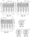
- FIGS 4A, 5A, 6A and 7 are schematic section views along the 3-3' line shown in FIG. 1B (i.e., parallel to the azimuthal direction) of transducer assemblies configured in accordance with examples not forming part of the invention ( FIGS 4A , 7 ) and embodiments ( FIGS 5A, 6A ) of the present invention.
- FIGS. 4B, 5B and 6B are enlarged views of corresponding portions FIGS. 4A, 5A and 6A .
- a transducer assembly 420 includes the first kerfs 342 and the second kerfs 344 having a groove 452 formed in the filler 348.
- the groove 452 has a width in the azimuthal direction substantially similar to widths of the first kerfs 342 and the second kerfs 344.
- the first kerfs 342 and the second kerfs 344 can have different groove depths.
- the groove 452 is filled with the same material (e.g., RTV) as the lens 222. In other examples, however, another material may be used.
- a transducer assembly 520 includes the first kerfs 342 and the second kerfs having a portion or groove 554 formed in the filler 348.
- the groove 554 has a smaller width in the azimuthal direction (e.g., 1/2 as wide, 1/4 as wide, 1/8 as wide) than the widths of the first kerfs 342 and the second kerfs 344.
- the first kerfs 342 and the second kerfs 344 can have differing groove depths.
- the groove 554 is filled with the same material (e.g., RTV) as the lens 222. In other embodiments, however, another material may be used.
- an ultrasound transducer assembly 620 includes the first kerfs 342 and the second kerfs having a portion or groove 656 formed in the filler 348.
- the groove 656 has a smaller width in the azimuthal direction (e.g., 1/2 as wide, 1/4 as wide, 1/8 as wide) than the widths of the first kerfs 342 and the second kerfs 344.
- the first kerfs 342 and the second kerfs 344 can have differing groove depths.
- the groove 656 is filled with the same material (e.g., RTV) as the lens 222. In other embodiments, however, another material may be used.
- an ultrasound transducer assembly 720 includes the first kerfs 342 and the second kerfs having a first filler material 752 (e.g., a polymer) above a second filler material 754 (e.g., a composite material comprising microballoons).
- first filler material 752 e.g., a polymer
- second filler material 754 e.g., a composite material comprising microballoons.
- grooves can be formed in the first filler material 752 as described above in reference to FIGS. 4A-6B .
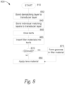
- FIG. 8 is a flow diagram of a process 800 of constructing an ultrasound transducer assembly. Although the process is not directly claimed, the resultant ultrasound transducer assembly may be in accordance with an embodiment of the invention.
- the process 800 begins.
- the process 800 bonds a lower surface of a transducer layer (e.g., the transducer layer 230 of FIG. 2 ) to an upper surface of the dematching layer using an adhesive (e.g., an epoxy, a polymer).
- an adhesive e.g., an epoxy, a polymer
- the process 800 bonds a first matching layer to the transducer layer and bonds one or more additional matching layer to the first matching layer.
- the process 800 can optionally bond a lower surface of a dematching layer (e.g., the dematching layer 234 of FIG. 2 ) to an upper surface of a backing layer (e.g., the backing layer 240 of FIG. 2 ) using an epoxy.
- the process 800 performs one or more cuts to form one or more kerfs (e.g., the first kerfs 342 or the second kerfs 344 of FIG. 3 ) in the transducer assembly.
- the process 800 inserts or otherwise fills at least a portion of the kerfs formed at block 850 with a filler material (e.g., a filler material comprising microballoons).
- a filler material e.g., a filler material comprising microballoons
- the process 800 determines whether one or more grooves is to be formed in the filler material inserted into the kerfs formed at block 860. If so, then the process 800 proceeds to block 875 and one or more kerfs are formed in the filler material inserted into the kerfs at block 860 (e.g., the grooves 452 of FIGS. 4A and 4B , the grooves 554 of FIGS. 5A and 5B and/or the grooves 656 of FIGS. 6A and 6B ).
- a lens material e.g., RTV or another suitable lens material
- the words “comprise,” “comprising,” and the like are to be construed in an inclusive sense, as opposed to an exclusive or exhaustive sense; that is to say, in the sense of "including, but not limited to.”
- the terms “connected,” “coupled,” or any variant thereof means any connection or coupling, either direct or indirect, between two or more elements; the coupling or connection between the elements can be physical, logical, or a combination thereof.
- the words “herein,” “above,” “below,” and words of similar import, when used in this application refer to this application as a whole and not to any particular portions of this application.
- transducer assemblies configured in accordance with the invention can include fewer than three matching layers, namely two matching layers. In other implementations, transducer assemblies can be configured in accordance with the disclosed technology without a dematching layer.
- the scope of the invention is defined by the appended claims.
Description
- The disclosed technology relates generally to ultrasound transducers, and more specifically ultrasound transducer assemblies configured for use with ultrasound imaging systems.
-
EP 0707898 A2 discloses a transducer device with integral transducer and impedance matching portions including grooves formed partially through a thickness of a piezoelectric member. A groove volume fraction at the impedance matching portion controls the electrical impedance. The impedance matching portion is at either or both of the front and rear surfaces of the transducer portion, which generates acoustic wave energy in response to application of a drive signal. The drive signal is introduced by electrodes. The electrode at the impedance matching portion extends into the grooves, and a filler material is selected and deposited to allow use of a planar electrode. The grooves are filled with filler material. This document does not disclose that the grooves contain internal grooves in the filler material in the matching layer adjacent to the lens, the internal grooves having a width in an azimuthal direction that is less than a width of the grooves in which they are contained and are filled with a second filler material, different than the filler material.US 2009/093722 A1 discloses an ultrasonic probe and ultrasonic diagnostic apparatus.US 6359375 B1 discloses a method to build a high bandwidth, low crosstalk, low EM noise transducer.US 2005/042424 A1 discloses electrically conductive matching layers and methods.US 2006/028099 A1 discloses a composite acoustic matching layer.JP S61 39700 A JP S59 25500 A -
-
FIG. 1A is a side view of an ultrasound probe having an ultrasound transducer assembly, the ultrasound transducer assembly may be configured in accordance with an embodiment of the invention. -
FIG. 1B is a schematic isometric view of a portion of the ultrasound transducer assembly ofFIG. 1A . -
FIG. 2 is a schematic section view of the ultrasound transducer assembly ofFIGS. 1A and1B along the 2-2' line shown inFIG. 1B . -
FIG. 3 is a schematic section view of an ultrasound transducer assembly ofFIGS. 1A and1B along the 3-3' line shown inFIG. 1B and configured in accordance with an example not forming part of the invention. -
FIG. 4A is a schematic section view of an ultrasound transducer assembly along the 3-3' line shown inFIG. 1B and configured in accordance with an example not forming part of the invention.FIG. 4B is an enlarged view of a portion ofFIG. 4A . -
FIG. 5A is schematic section view of an ultrasound transducer assembly along the 3-3' line shown inFIG. 1B and configured in accordance with an embodiment of the invention.FIG. 5B is an enlarged view of a portion ofFIG. 5A . -
FIG. 6A is a schematic section view of an ultrasound transducer assembly along the 3-3' line shown inFIG. 1B and configured in accordance with another embodiment of the invention.FIG. 6B is an enlarged view of a portion ofFIG. 6A . -
FIG. 7 is a schematic section view of an ultrasound transducer assembly along the 3-3' line shown inFIG. 1B and configured in accordance with an example not forming part of the invention. -
FIG. 8 is a flow diagram of a method of constructing an ultrasound transducer assembly. Although the process is not directly claimed, the resultant ultrasound transducer assembly may be configured in accordance with an embodiment of the invention. - The present invention provides ultrasound transducer assemblies as recited in the claims.
- It will be appreciated that several of the details set forth below are provided to describe the following embodiments of the disclosed technology in a manner sufficient to enable a person skilled in the relevant art to make and use the disclosed technology. Several of the details described below, however, may not be necessary to practice the invention. Additionally, the invention can include other embodiments that are within the scope of the claims but are not described in detail with reference to the Figures.
- Certain details are set forth in the following description and in
FIGS. 1A-8 to provide a thorough understanding of the technology. Other details describing well-known methods and systems often associated with ultrasound imaging, however, are not set forth below to avoid unnecessarily obscuring the description of the various embodiments of the technology. Many of the details, dimensions, angles and other features shown in the Figures are merely illustrative of particular embodiments of the disclosure. Accordingly, other embodiments can have other details, dimensions, angles and features without departing from the scope of the present invention as defined in the appended claims. - In the Figures, identical reference numbers identify identical, or at least generally similar, elements. To facilitate the discussion of any particular element, the most significant digits or digits of any reference number refer to the Figure in which that element is first introduced. For example,
element 120 is first introduced and discussed with reference toFIG. 1A . -
FIG. 1A is a side view of anultrasound transducer probe 100 having anultrasound transducer assembly 120. The ultrasound transducer assembly may be configured in accordance with an example forming part of the invention.FIG. 1B is a schematic isometric side view of a portion of thetransducer assembly 120 showing the azimuthal (e.g., along an x-axis), elevation (e.g., along a y-axis) and axial (e.g., along a z-axis) dimensions of thetransducer assembly 120. Referring now toFIG. 1A , theprobe 100 includes anenclosure 110 extending between adistal end portion 112 and aproximal end portion 114. Theenclosure 110 is configured to carry or house system electronics 116 (e.g., one or more processors, integrated circuits, ASICs, FPGAs, beamformers, batteries and/or other power sources) disposed in an interior portion or cavity of theenclosure 110. Thesystem electronics 116 are electrically coupled to anultrasound imaging system 117 via acable 118 that is attached to the proximal end of the probe by astrain relief element 119. Atransducer assembly 120 having one or more transducer elements is electrically coupled to thesystem electronics 116. In operation, thetransducer assembly 120 transmits ultrasound energy from the one or more transducer elements toward a subject and receives ultrasound echoes from the subject. The ultrasound echoes are converted into electrical signals by the one or more transducer elements and electrically transmitted to thesystem electronics 116 and to electronics (e.g., one or more processors, memory modules, beamformers, FPGAs) in theultrasound imaging system 117 configured to process the electrical signals and form one or more ultrasound images. - Capturing ultrasound data from a subject using an exemplary transducer assembly (e.g., the transducer assembly 120) generally includes generating ultrasound, transmitting ultrasound into the subject, and receiving ultrasound reflected by the subject. A wide range of frequencies of ultrasound may be used to capture ultrasound data, such as, for example, low frequency ultrasound (e.g., less than 15 MHz) and/or high frequency ultrasound (e.g., greater than or equal to 15 MHz) can be used. Those of ordinary skill in the art can readily determine which frequency range to use based on factors such as, for example, but not limited to, depth of imaging and/or desired resolution.
-
FIG. 2 is a schematic section view of thetransducer assembly 120 ofFIGS. 1A and1B shown along the 2-2' line shown inFIG. 1B . Atransducer layer 230 includes one or more transducer elements configured to emit ultrasound energy at a center operating frequency (e.g., between 1 MHz and about 10 MHz). In some examples, thetransducer layer 230 ie-comprises a piezoelectric material (e.g., lead zirconate titanate, i.e. PZT). In some examples, thetransducer layer 230 comprises a piezoelectric micromachined ultrasound transducer (PMUT) or a capacitive micromachined ultrasound transducer (CMUT). In some examples, thetransducer layer 230 comprises an electrostrictive ceramic material. In some examples, thetransducer layer 230 comprises another suitable transducer material. - An
acoustic lens 222 overlies thetransducer layer 230 and comprises an acoustically transparent material such as, for example, room temperature vulcanization silicone (RTV) or another suitable acoustic material. A plurality of matching layers 224 is positioned between thelens 222 and thetransducer layer 230. Abacking layer 240 underlies thetransducer layer 230 and is configured to absorb and dissipate acoustic and thermal energy produced by transducer elements of thetransducer layer 230. In some examples, thebacking layer 240 comprises a loaded epoxy (e.g., an epoxy loaded with tungsten particles) and/or another suitable material having one or more plates (not shown) extending therethrough. - A
dematching layer 234 is positioned between thetransducer layer 230 and thebacking layer 240. Thedematching layer 234 is configured to reflect rearward propagating ultrasound energy from the transducer layer 230 (i.e., toward the backing layer 240) back toward the front of the transducer assembly 120 (i.e., toward the lens 222) and away from thebacking layer 240. In some examples, thedematching layer 234 comprises a material that has an acoustic impedance significantly different than an acoustic impedance of thetransducer layer 230. In the following, this conversion is considered: 1 Rayl = 1 kg.s-1.m-2. In one example, for example, thedematching layer 234 comprises tungsten carbide (WC), which has an acoustic impedance of approximately 100 MRayls, which is significantly greater than the acoustic impedance of PZT (approximately 34 MRayls). - In other examples, however, the
dematching layer 234 includes one or more materials having a lower acoustic impedance than the acoustic impedance of WC (e.g., approximately 100 MRayls) and thetransducer layer 230. In some examples, thedematching layer 234 comprises aluminum nitride (AIN), which has an acoustical impedance of approximately 33 MRayls. In some examples, thedematching layer 234 comprises polycrystalline silicon, which has an acoustical impedance of approximately 22 MRayls. In some examples, thedematching layer 234 comprises copper loaded graphite having an acoustical impedance between about 8MRayls and about 15MRayls, or about 10.7MRayls. In some examples, another suitable dematching layer can be used. - A plurality of matching layers 224 (identified separately as a
first matching layer 224A, asecond matching layer 224B and athird matching layer 224C) are positioned between thetransducer layer 230 and thelens 222. In some examples, an acoustical impedance (e.g., between about 20 MRayls and about 35 MRayls) of thetransducer layer 230 is greater than an acoustical impedance (e.g., between about 10 MRayls and about 20 MRayls) of thefirst matching layer 224A. In some examples, the acoustic impedance of thefirst matching layer 224A is greater than an acoustical impedance (e.g., between about 5 MRayls and about 10 MRayls) of thesecond matching layer 224B. In some examples, the acoustical impedance of thesecond matching layer 224B is greater than an acoustical impedance (between about 2 MRayls and about 5 MRayls) of thethird matching layer 224C. Moreover, in the illustrated example ofFIG. 2 , thetransducer assembly 120 includes three matching layers 224. In the invention, thetransducer assembly 120 includes at least two matching layers 224. In other embodiments, thetransducer assembly 120 includes four or more matching layers 224. -
FIG. 3 is a schematic section view of thetransducer assembly 120 ofFIG. 1B along the 3-3' line shown inFIG. 1B (i.e., parallel to the azimuthal axis), and configured in accordance with various examples not forming part of the invention. A plurality of trenches, grooves orfirst kerfs 342 extend into the transducer assembly 120 a first depth in the axial direction. A plurality of trenches, grooves orsecond kerfs 344 extend a second depth in the axial direction. In the invention, the second depth is greater than the first depth. In other examples not forming part of the invention, however, the first and second depths can be substantially equal. As those of ordinary skill in the art will appreciate, thefirst kerfs 342 and thesecond kerfs 344 can be configured to isolate individual elements of thetransducer layer 230 and/or attenuate acoustic crosstalk between the individual elements. Thefirst kerfs 342 and thesecond kerfs 344 are at least partially filled with afiller 348. - In the illustrated example, the
first kerfs 342 extend through the matching layers 224 while thesecond kerfs 344 extend through the matching layers 224, thetransducer layer 230 and thedematching layer 234, and extend into thebacking layer 240. In other examples, however, thefirst kerfs 342 and thesecond kerfs 344 can extend to lesser or greater depths relative to the axial direction than shown inFIG. 3 . In some examples not forming part of the invention, thefirst kerfs 342 and thesecond kerfs 344 have the same depths relative to the axial direction but are filled with different materials. Moreover, In some embodiments, thefirst kerfs 342 and thesecond kerf 344 have a same or similar width (e.g., between about 0.01mm and about 0.1mm). In other embodiments, however, thefirst kerfs 342 have a first width that differs from a second width of thesecond kerfs 344. - The
filler 348 comprises one or more materials that fill at least a portion of thefirst kerfs 342 and thesecond kerfs 344. In the illustrated example, the depths of thefiller 348 in individualfirst kerfs 342 is substantially the same. Similarly, the depths of thefiller 348 in individualsecond kerfs 344 is also substantially the same. In some examples, however, the depths of thefiller material 348 in the individualfirst kerfs 342 and in the individual second kerfs vary in an elevation direction. In some examples, an apodized (stepped or curved) depth profile from the edges towards center of thetransducer assembly 120 can be utilized. In some examples not forming part of the invention, thefirst kerfs 342 and thesecond kerfs 344 are filled with different filler materials. - In some examples, the
filler 348 comprises a composite material that includes microballoons suspended in an epoxy or a polymer. The microballoons can include glass or plastic microspheres surrounding or encapsulating a gas (e.g., air, or a hydrocarbon gas) or be solid microspheres. The microballoons or microspheres can be mixed with an epoxy or polymer in varying ratios to achieve composite materials having varying consistencies and densities. In some examples, for example, a "slurry" composite material is mixed with microballoons and epoxy or a polymer. - In some examples, the
filler 348 includes a composite material comprising one or more materials, for example, having a density between about 0.0005 g/cm3 and about 0.1 g/cm3 or between about 0.001 g/cm3 and about 0.01 g/cm3 or about 0.0012 g/cm3 In some examples, the filler material comprises a composite material having an acoustical impedance within 10% or less of an acoustical impedance of air. In some examples, thefiller 348 comprises microballoons, an aerogel or a foam. In some examples, thefiller 348 comprises a composite material that has a graduated acoustical impedance such that the material has an acoustical impedance that varies in the axial direction of thetransducer assembly 120. In one example, the graduated acoustical impedance material has an acoustical impedance that decreases with increasing height in the axial direction. - As those of ordinary skill in the art will appreciate, conventional transducer assemblies may include piezoelectric transducers, two matching layers, no dematching layer and kerfs filled with conventional material (e.g., a lens material such as RTV). Such conventional transducer assemblies can have a typical -6dB bandwidth of 75%. Embodiments of the disclosed technology are expected to provide a benefit of a significant performance increase in bandwidth and efficiency compared to conventional piezoelectric transducer assemblies. Certain embodiments of the disclosed technology, for example, include transducer assemblies that include a -6dB fractional bandwidth of up to 120% and upto a 8dB sensitivity gain relative to conventional piezoelectric transducer designs. Embodiments of the disclosed technology are expected to provide an additional benefit of higher mechanical indices (and thus deeper imaging penetration) with lower transmit voltages with similar or identical surface temperatures as conventional piezoelectric transducer assemblies.
-
FIGS 4A, 5A, 6A and7 are schematic section views along the 3-3' line shown inFIG. 1B (i.e., parallel to the azimuthal direction) of transducer assemblies configured in accordance with examples not forming part of the invention (FIGS 4A ,7 ) and embodiments (FIGS 5A, 6A ) of the present invention.FIGS. 4B, 5B and 6B are enlarged views of corresponding portionsFIGS. 4A, 5A and 6A . - Referring first to
FIG. 4 , atransducer assembly 420 includes thefirst kerfs 342 and thesecond kerfs 344 having agroove 452 formed in thefiller 348. Thegroove 452 has a width in the azimuthal direction substantially similar to widths of thefirst kerfs 342 and thesecond kerfs 344. In some examples, thefirst kerfs 342 and thesecond kerfs 344 can have different groove depths. In the illustrated example ofFIGS. 4A and 4B , thegroove 452 is filled with the same material (e.g., RTV) as thelens 222. In other examples, however, another material may be used. - Referring next to
FIG. 5 , atransducer assembly 520 includes thefirst kerfs 342 and the second kerfs having a portion or groove 554 formed in thefiller 348. Thegroove 554 has a smaller width in the azimuthal direction (e.g., 1/2 as wide, 1/4 as wide, 1/8 as wide) than the widths of thefirst kerfs 342 and thesecond kerfs 344. In some embodiments, thefirst kerfs 342 and thesecond kerfs 344 can have differing groove depths. In the illustrated embodiment ofFIGS. 5A and 5B , thegroove 554 is filled with the same material (e.g., RTV) as thelens 222. In other embodiments, however, another material may be used. - Referring next to
FIG. 6 , anultrasound transducer assembly 620 includes thefirst kerfs 342 and the second kerfs having a portion or groove 656 formed in thefiller 348. Thegroove 656 has a smaller width in the azimuthal direction (e.g., 1/2 as wide, 1/4 as wide, 1/8 as wide) than the widths of thefirst kerfs 342 and thesecond kerfs 344. In some embodiments, thefirst kerfs 342 and thesecond kerfs 344 can have differing groove depths. In the illustrated embodiment ofFIGS. 5A and 5B , thegroove 656 is filled with the same material (e.g., RTV) as thelens 222. In other embodiments, however, another material may be used. - Referring now to
FIG. 7 , anultrasound transducer assembly 720 includes thefirst kerfs 342 and the second kerfs having a first filler material 752 (e.g., a polymer) above a second filler material 754 (e.g., a composite material comprising microballoons). In some examples, grooves can be formed in thefirst filler material 752 as described above in reference toFIGS. 4A-6B . -
FIG. 8 is a flow diagram of aprocess 800 of constructing an ultrasound transducer assembly. Although the process is not directly claimed, the resultant ultrasound transducer assembly may be in accordance with an embodiment of the invention.
Atblock 810, theprocess 800 begins. Atblock 830, theprocess 800 bonds a lower surface of a transducer layer (e.g., thetransducer layer 230 ofFIG. 2 ) to an upper surface of the dematching layer using an adhesive (e.g., an epoxy, a polymer). Atblock 840, theprocess 800 bonds a first matching layer to the transducer layer and bonds one or more additional matching layer to the first matching layer. In some examples, theprocess 800 can optionally bond a lower surface of a dematching layer (e.g., thedematching layer 234 ofFIG. 2 ) to an upper surface of a backing layer (e.g., thebacking layer 240 ofFIG. 2 ) using an epoxy. Atblock 850, theprocess 800 performs one or more cuts to form one or more kerfs (e.g., thefirst kerfs 342 or thesecond kerfs 344 ofFIG. 3 ) in the transducer assembly. Atblock 860, theprocess 800 inserts or otherwise fills at least a portion of the kerfs formed atblock 850 with a filler material (e.g., a filler material comprising microballoons). - At
decision block 870, theprocess 800 determines whether one or more grooves is to be formed in the filler material inserted into the kerfs formed atblock 860. If so, then theprocess 800 proceeds to block 875 and one or more kerfs are formed in the filler material inserted into the kerfs at block 860 (e.g., thegrooves 452 ofFIGS. 4A and 4B , thegrooves 554 ofFIGS. 5A and 5B and/or thegrooves 656 ofFIGS. 6A and 6B ). Atblock 880, a lens material (e.g., RTV or another suitable lens material) is applied onto the front (i.e., on the uppermost matching layer) of the transducer assembly. - Unless the context clearly requires otherwise, throughout the description and the claims, the words "comprise," "comprising," and the like are to be construed in an inclusive sense, as opposed to an exclusive or exhaustive sense; that is to say, in the sense of "including, but not limited to." As used herein, the terms "connected," "coupled," or any variant thereof means any connection or coupling, either direct or indirect, between two or more elements; the coupling or connection between the elements can be physical, logical, or a combination thereof. Additionally, the words "herein," "above," "below," and words of similar import, when used in this application, refer to this application as a whole and not to any particular portions of this application. Where the context permits, words in the above Detailed Description using the singular or plural number may also include the plural or singular number respectively. The word "or," in reference to a list of two or more items, covers all of the following interpretations of the word: any of the items in the list, all of the items in the list, and any combination of the items in the list.
- The above Detailed Description of examples of the disclosed technology is not intended to be exhaustive or to limit the disclosed technology to the precise form disclosed above. While specific examples for the disclosed technology are described above for illustrative purposes, it should be understood that various changes, substitutions, and alterations could be made hereto without departing from the scope of the invention, as defined by the appended claims.
- The teachings of the disclosed technology provided herein can be applied to other systems, not necessarily the system described above. The elements and acts of the various examples described above can be combined to provide further implementations of the disclosed technology. Some alternative implementations of the disclosed technology may include not only additional elements to those implementations noted above, but also may include fewer elements. The transducer assemblies configured in accordance with the invention can include fewer than three matching layers, namely two matching layers. In other implementations, transducer assemblies can be configured in accordance with the disclosed technology without a dematching layer. The scope of the invention is defined by the appended claims.
Claims (12)
- An ultrasound transducer assembly (520), comprising:a transducer layer (230) configured to emit ultrasound energy in an axial direction;a plurality of matching layers comprising a first matching layer (224C) on a second matching layer (224B) overlaying the transducer layer (230) in the axial direction;a lens (222) on the first matching layer (224C); anda plurality of kerfs comprising first kerfs (342) and second kerfs (344) extending from the lens (222) into the plurality of matching layers (224), wherein each of the first kerfs (342) and the second kerfs (344) is filled with a first filler material (348) and contains a groove (554) in the first filler material (348) in said each of the first kerfs (342) and the second kerfs (344) in the first matching layer (224C) adjacent to the lens (222), the groove (554) having a width in an azimuthal direction that is less than a width of said each of the first kerfs (342) and the second kerfs (344) in which the groove (554) is contained and is filled with a second filler material different than the first filler material, wherein the first kerfs (342) have a first depth in the axial direction and the second kerfs (344) have a second depth in the axial direction that is greater than the first depth.
- The transducer assembly (520) of claim 1, further comprising a backing layer (240) behind the transducer layer (230) and a dematching layer (234) between the transducer layer (230) and the backing layer (240), wherein the second kerfs (344) extend into the backing layer (240) through the plurality of matching layers (224), the transducer layer (230) and the dematching layer (234).
- The ultrasound transducer assembly (520) of claim 1, wherein the first kerfs (342) have a first width in the azimuthal direction of the transducer assembly (520) and the second kerfs (344) have a second width in the azimuthal direction of the transducer assembly (520) that is different to the first width.
- The transducer assembly (520) of claim 3, wherein the depths of first filler material (348) in individual first kerfs (342) and in individual second kerfs (344) vary.
- The transducer assembly of claim 1, wherein the first filler material (348) has a stepped or curved depth profile from edges of the transducer assembly (520) towards a center of the transducer assembly (520).
- The transducer assembly (520) of claim 1, wherein the first kerfs (342) and the second kerfs (344) are filled with a composite material that has a graduated acoustic impedance, such that the acoustic impedance varies in the axial direction of the transducer assembly (520).
- The transducer assembly (520) of claim 6, wherein the graduated acoustic impedance decreases with increasing height in the axial direction of the transducer assembly (520).
- The transducer assembly (520) of claim 1, wherein the groove (554) width is one half of the width of the kerf (342, 344) in which the groove (554) is contained.
- The transducer assembly (520) of claim 1, wherein the groove (554) width is one quarter of the width of the kerf (342, 344) in which the groove (554) is contained.
- The transducer assembly (520) of claim 1, wherein two or more kerfs (342, 344) of the transducer assembly (520) have grooves (554) with differing depths in an axial direction of the transducer assembly (520).
- The transducer assembly (520) of claim 1, wherein the second filler material is the same as the material used for the lens (222).
- The transducer assembly (520) of claim 1, wherein the second filler material is different than the material used for the lens (222).
Priority Applications (1)
| Application Number | Priority Date | Filing Date | Title |
|---|---|---|---|
| EP23163129.2A EP4219026A1 (en) | 2015-09-03 | 2016-09-02 | Ultrasound transducer assembly |
Applications Claiming Priority (2)
| Application Number | Priority Date | Filing Date | Title |
|---|---|---|---|
| US201562214185P | 2015-09-03 | 2015-09-03 | |
| PCT/US2016/050171 WO2017040979A1 (en) | 2015-09-03 | 2016-09-02 | Ultrasound transducer assembly |
Related Child Applications (2)
| Application Number | Title | Priority Date | Filing Date |
|---|---|---|---|
| EP23163129.2A Division EP4219026A1 (en) | 2015-09-03 | 2016-09-02 | Ultrasound transducer assembly |
| EP23163129.2A Division-Into EP4219026A1 (en) | 2015-09-03 | 2016-09-02 | Ultrasound transducer assembly |
Publications (3)
| Publication Number | Publication Date |
|---|---|
| EP3344147A1 EP3344147A1 (en) | 2018-07-11 |
| EP3344147A4 EP3344147A4 (en) | 2019-05-22 |
| EP3344147B1 true EP3344147B1 (en) | 2023-11-01 |
Family
ID=58188539
Family Applications (2)
| Application Number | Title | Priority Date | Filing Date |
|---|---|---|---|
| EP23163129.2A Pending EP4219026A1 (en) | 2015-09-03 | 2016-09-02 | Ultrasound transducer assembly |
| EP16843099.9A Active EP3344147B1 (en) | 2015-09-03 | 2016-09-02 | Ultrasound transducer assembly |
Family Applications Before (1)
| Application Number | Title | Priority Date | Filing Date |
|---|---|---|---|
| EP23163129.2A Pending EP4219026A1 (en) | 2015-09-03 | 2016-09-02 | Ultrasound transducer assembly |
Country Status (6)
| Country | Link |
|---|---|
| US (2) | US10716542B2 (en) |
| EP (2) | EP4219026A1 (en) |
| JP (1) | JP6911013B2 (en) |
| KR (1) | KR102633430B1 (en) |
| CN (1) | CN107920797B (en) |
| WO (1) | WO2017040979A1 (en) |
Families Citing this family (13)
| Publication number | Priority date | Publication date | Assignee | Title |
|---|---|---|---|---|
| US9808830B2 (en) * | 2013-12-27 | 2017-11-07 | General Electric Company | Ultrasound transducer and ultrasound imaging system with a variable thickness dematching layer |
| KR20170090304A (en) * | 2016-01-28 | 2017-08-07 | 삼성메디슨 주식회사 | Ultrasonic transducer and ultrasonic probe including the same |
| USD831219S1 (en) * | 2017-07-31 | 2018-10-16 | Edan Instruments, Inc. | Transducer |
| US11678865B2 (en) * | 2017-12-29 | 2023-06-20 | Fujifilm Sonosite, Inc. | High frequency ultrasound transducer |
| CA3107647A1 (en) * | 2018-07-31 | 2020-02-06 | Resonant Acoustics International Inc. | Ultrasonic transducer |
| CN109530196B (en) * | 2018-11-28 | 2023-10-27 | 深圳先进技术研究院 | Transducer assembly and method of making the same |
| WO2020107283A1 (en) * | 2018-11-28 | 2020-06-04 | 深圳先进技术研究院 | Transducer assembly, and manufacturing method for same |
| US11583259B2 (en) * | 2018-12-19 | 2023-02-21 | Fujifilm Sonosite, Inc. | Thermal conductive layer for transducer face temperature reduction |
| WO2020190593A1 (en) * | 2019-03-15 | 2020-09-24 | EchoNous, Inc. | Ultrasound transducer assembly having low viscosity kerf fill material |
| CA3134525A1 (en) * | 2019-03-25 | 2020-10-01 | Exo Imaging, Inc. | Handheld ultrasound imager |
| CA3158819A1 (en) * | 2019-11-18 | 2021-05-27 | Nicholas Chris CHAGGARES | Ultrasonic transducers, backing structures and related methods |
| JP2021136675A (en) * | 2020-02-28 | 2021-09-13 | 学校法人早稲田大学 | Piezoelectric device |
| CN113180727B (en) * | 2021-03-29 | 2023-03-03 | 聚融医疗科技(杭州)有限公司 | Ultrasonic transducer with freely selectable joint filling material and preparation method thereof |
Family Cites Families (36)
| Publication number | Priority date | Publication date | Assignee | Title |
|---|---|---|---|---|
| JPS5315486U (en) | 1976-07-21 | 1978-02-08 | ||
| JPS6029731B2 (en) * | 1977-04-26 | 1985-07-12 | 旭化成株式会社 | Polycondensation method |
| JPS5925500A (en) * | 1982-08-02 | 1984-02-09 | Matsushita Electric Ind Co Ltd | Production of ultrasonic wave probe |
| JPS6139700A (en) * | 1984-07-30 | 1986-02-25 | Shimadzu Corp | Manufacture of ultrasonic probe |
| JPS6139700U (en) | 1984-08-15 | 1986-03-13 | 三菱重工業株式会社 | Engine room air supply system |
| EP0379229B1 (en) * | 1985-05-20 | 1994-07-27 | Matsushita Electric Industrial Co., Ltd. | Ultrasonic probe |
| JP2794720B2 (en) | 1988-08-23 | 1998-09-10 | 松下電器産業株式会社 | Composite piezoelectric vibrator |
| US5311095A (en) * | 1992-05-14 | 1994-05-10 | Duke University | Ultrasonic transducer array |
| US5553035A (en) * | 1993-06-15 | 1996-09-03 | Hewlett-Packard Company | Method of forming integral transducer and impedance matching layers |
| US5648942A (en) * | 1995-10-13 | 1997-07-15 | Advanced Technology Laboratories, Inc. | Acoustic backing with integral conductors for an ultrasonic transducer |
| JP3673035B2 (en) * | 1996-10-25 | 2005-07-20 | 株式会社東芝 | Ultrasonic transducer |
| US6359375B1 (en) * | 1998-05-06 | 2002-03-19 | Siemens Medical Solutions Usa, Inc. | Method to build a high bandwidth, low crosstalk, low EM noise transducer |
| JP2003175036A (en) | 2001-12-11 | 2003-06-24 | Aloka Co Ltd | Ultrasonic probe and ultrasonic diagnostic apparatus |
| JP3908595B2 (en) | 2002-05-17 | 2007-04-25 | アロカ株式会社 | Ultrasonic probe |
| US20040190377A1 (en) * | 2003-03-06 | 2004-09-30 | Lewandowski Robert Stephen | Method and means for isolating elements of a sensor array |
| US7368852B2 (en) * | 2003-08-22 | 2008-05-06 | Siemens Medical Solutions Usa, Inc. | Electrically conductive matching layers and methods |
| US7285897B2 (en) * | 2003-12-31 | 2007-10-23 | General Electric Company | Curved micromachined ultrasonic transducer arrays and related methods of manufacture |
| US20070222339A1 (en) * | 2004-04-20 | 2007-09-27 | Mark Lukacs | Arrayed ultrasonic transducer |
| JP2005340903A (en) * | 2004-05-24 | 2005-12-08 | Olympus Corp | Ultrasonic wave transducer and its manufacturing method |
| US20060028099A1 (en) * | 2004-08-05 | 2006-02-09 | Frey Gregg W | Composite acoustic matching layer |
| JP4933392B2 (en) * | 2007-04-02 | 2012-05-16 | 富士フイルム株式会社 | Ultrasonic probe and manufacturing method thereof |
| JP5002402B2 (en) * | 2007-10-03 | 2012-08-15 | 株式会社東芝 | Ultrasonic probe and ultrasonic diagnostic apparatus |
| US8378557B2 (en) * | 2010-07-09 | 2013-02-19 | General Electric Company | Thermal transfer and acoustic matching layers for ultrasound transducer |
| JP5643667B2 (en) | 2011-01-28 | 2014-12-17 | 株式会社東芝 | Ultrasonic transducer, ultrasonic probe, and method of manufacturing ultrasonic transducer |
| JP5468564B2 (en) * | 2011-03-30 | 2014-04-09 | 富士フイルム株式会社 | Ultrasonic probe and ultrasonic diagnostic apparatus |
| JP6548201B2 (en) * | 2011-09-16 | 2019-07-24 | ゼネラル・エレクトリック・カンパニイ | Heat transfer and acoustic matching layer for ultrasonic transducers |
| KR101269459B1 (en) | 2011-12-13 | 2013-05-30 | 삼성전자주식회사 | Ultrasound probe and manufacturing method thereof |
| KR101477544B1 (en) | 2012-01-02 | 2014-12-31 | 삼성전자주식회사 | Ultrasonic transducer, ultrasonic probe, and ultrasound image diagnosis apparatus |
| CN103429166B (en) * | 2012-01-30 | 2015-06-17 | 奥林巴斯医疗株式会社 | Ultrasonic vibrator array, method for manufacturing ultrasonic vibrator array, and ultrasonic endoscope |
| JP6029731B2 (en) | 2012-02-07 | 2016-11-24 | 富士フイルム株式会社 | Ultrasonic probe |
| JP5924298B2 (en) * | 2013-03-19 | 2016-05-25 | コニカミノルタ株式会社 | Ultrasonic probe and ultrasonic diagnostic imaging apparatus |
| JP2014188009A (en) | 2013-03-26 | 2014-10-06 | Konica Minolta Inc | Ultrasonic probe, ultrasonic image diagnostic apparatus, and method of manufacturing ultrasonic probe |
| JP6214333B2 (en) * | 2013-10-23 | 2017-10-18 | 三菱鉛筆株式会社 | Acoustic matching layer and manufacturing method thereof |
| JP5665948B1 (en) * | 2013-11-14 | 2015-02-04 | 株式会社フジクラ | Cooling structure for portable electronic devices |
| CN105917157B (en) | 2013-12-02 | 2019-08-16 | 株式会社东芝 | Leak inhibits device, leak to inhibit system and computer-readable storage medium |
| JP6641723B2 (en) | 2015-05-08 | 2020-02-05 | コニカミノルタ株式会社 | Ultrasonic transducer and manufacturing method thereof, ultrasonic probe, and ultrasonic imaging apparatus |
-
2016
- 2016-09-02 KR KR1020187005215A patent/KR102633430B1/en active IP Right Grant
- 2016-09-02 CN CN201680049560.3A patent/CN107920797B/en active Active
- 2016-09-02 EP EP23163129.2A patent/EP4219026A1/en active Pending
- 2016-09-02 WO PCT/US2016/050171 patent/WO2017040979A1/en active Application Filing
- 2016-09-02 US US15/256,029 patent/US10716542B2/en active Active
- 2016-09-02 EP EP16843099.9A patent/EP3344147B1/en active Active
- 2016-09-02 JP JP2018511677A patent/JP6911013B2/en active Active
-
2020
- 2020-07-20 US US16/933,822 patent/US11890140B2/en active Active
Also Published As
| Publication number | Publication date |
|---|---|
| CN107920797A (en) | 2018-04-17 |
| CN107920797B (en) | 2021-02-12 |
| EP4219026A1 (en) | 2023-08-02 |
| US10716542B2 (en) | 2020-07-21 |
| US11890140B2 (en) | 2024-02-06 |
| US20200345328A1 (en) | 2020-11-05 |
| JP6911013B2 (en) | 2021-07-28 |
| US20170065253A1 (en) | 2017-03-09 |
| KR20180038467A (en) | 2018-04-16 |
| EP3344147A1 (en) | 2018-07-11 |
| KR102633430B1 (en) | 2024-02-02 |
| EP3344147A4 (en) | 2019-05-22 |
| JP2018532307A (en) | 2018-11-01 |
| WO2017040979A1 (en) | 2017-03-09 |
Similar Documents
| Publication | Publication Date | Title |
|---|---|---|
| EP3344147B1 (en) | Ultrasound transducer assembly | |
| US11800806B2 (en) | Method for manufacturing a multi-cell transducer | |
| US8207652B2 (en) | Ultrasound transducer with improved acoustic performance | |
| JP4945769B2 (en) | Dual frequency ultrasonic transducer array | |
| JP6373024B2 (en) | Acoustic lens for micromachined ultrasonic transducers | |
| KR101354603B1 (en) | Ultrasound Probe and Manufacturing Method thereof | |
| US8378557B2 (en) | Thermal transfer and acoustic matching layers for ultrasound transducer | |
| WO2006062164A1 (en) | Ultrasonic probe and ultrasonic diagnosis device | |
| US9799818B2 (en) | Ultrasound probe with heat collecting portion | |
| KR20130030226A (en) | Thermal transfer and acoustic matching layers for ultrasound transducer | |
| US20230181167A1 (en) | Thermal conductive layer for transducer face temperature reduction | |
| US11691177B2 (en) | Ultrasound probe with acoustic amplifier | |
| KR20160096935A (en) | Ultrasonic Transducer for Improving Accoustic and Heat Characteristic | |
| JP2007124220A (en) | Ultrasonic probe and ultrasonic diagnostic device |
Legal Events
| Date | Code | Title | Description |
|---|---|---|---|
| STAA | Information on the status of an ep patent application or granted ep patent |
Free format text: STATUS: THE INTERNATIONAL PUBLICATION HAS BEEN MADE |
|
| PUAI | Public reference made under article 153(3) epc to a published international application that has entered the european phase |
Free format text: ORIGINAL CODE: 0009012 |
|
| STAA | Information on the status of an ep patent application or granted ep patent |
Free format text: STATUS: REQUEST FOR EXAMINATION WAS MADE |
|
| 17P | Request for examination filed |
Effective date: 20180322 |
|
| AK | Designated contracting states |
Kind code of ref document: A1 Designated state(s): AL AT BE BG CH CY CZ DE DK EE ES FI FR GB GR HR HU IE IS IT LI LT LU LV MC MK MT NL NO PL PT RO RS SE SI SK SM TR |
|
| AX | Request for extension of the european patent |
Extension state: BA ME |
|
| DAV | Request for validation of the european patent (deleted) | ||
| DAX | Request for extension of the european patent (deleted) | ||
| A4 | Supplementary search report drawn up and despatched |
Effective date: 20190424 |
|
| RIC1 | Information provided on ipc code assigned before grant |
Ipc: H01L 41/09 20060101ALI20190416BHEP Ipc: A61B 8/00 20060101ALI20190416BHEP Ipc: H01L 41/312 20130101ALI20190416BHEP Ipc: H01L 41/338 20130101ALI20190416BHEP Ipc: B06B 1/06 20060101AFI20190416BHEP |
|
| STAA | Information on the status of an ep patent application or granted ep patent |
Free format text: STATUS: EXAMINATION IS IN PROGRESS |
|
| 17Q | First examination report despatched |
Effective date: 20210609 |
|
| STAA | Information on the status of an ep patent application or granted ep patent |
Free format text: STATUS: EXAMINATION IS IN PROGRESS |
|
| GRAP | Despatch of communication of intention to grant a patent |
Free format text: ORIGINAL CODE: EPIDOSNIGR1 |
|
| STAA | Information on the status of an ep patent application or granted ep patent |
Free format text: STATUS: GRANT OF PATENT IS INTENDED |
|
| INTG | Intention to grant announced |
Effective date: 20221025 |
|
| GRAJ | Information related to disapproval of communication of intention to grant by the applicant or resumption of examination proceedings by the epo deleted |
Free format text: ORIGINAL CODE: EPIDOSDIGR1 |
|
| STAA | Information on the status of an ep patent application or granted ep patent |
Free format text: STATUS: EXAMINATION IS IN PROGRESS |
|
| REG | Reference to a national code |
Ref document number: 602016083893 Country of ref document: DE Ref country code: DE Ref legal event code: R079 Free format text: PREVIOUS MAIN CLASS: A61B0008000000 Ipc: B06B0001060000 |
|
| GRAP | Despatch of communication of intention to grant a patent |
Free format text: ORIGINAL CODE: EPIDOSNIGR1 |
|
| STAA | Information on the status of an ep patent application or granted ep patent |
Free format text: STATUS: GRANT OF PATENT IS INTENDED |
|
| INTC | Intention to grant announced (deleted) | ||
| RIC1 | Information provided on ipc code assigned before grant |
Ipc: H10N 30/20 20230101ALI20230309BHEP Ipc: H10N 30/072 20230101ALI20230309BHEP Ipc: H10N 30/088 20230101ALI20230309BHEP Ipc: A61B 8/00 20060101ALI20230309BHEP Ipc: B06B 1/06 20060101AFI20230309BHEP |
|
| INTG | Intention to grant announced |
Effective date: 20230321 |
|
| GRAS | Grant fee paid |
Free format text: ORIGINAL CODE: EPIDOSNIGR3 |
|
| GRAA | (expected) grant |
Free format text: ORIGINAL CODE: 0009210 |
|
| STAA | Information on the status of an ep patent application or granted ep patent |
Free format text: STATUS: THE PATENT HAS BEEN GRANTED |
|
| AK | Designated contracting states |
Kind code of ref document: B1 Designated state(s): AL AT BE BG CH CY CZ DE DK EE ES FI FR GB GR HR HU IE IS IT LI LT LU LV MC MK MT NL NO PL PT RO RS SE SI SK SM TR |
|
| REG | Reference to a national code |
Ref country code: GB Ref legal event code: FG4D |
|
| REG | Reference to a national code |
Ref country code: CH Ref legal event code: EP |
|
| REG | Reference to a national code |
Ref country code: DE Ref legal event code: R096 Ref document number: 602016083893 Country of ref document: DE |
|
| REG | Reference to a national code |
Ref country code: IE Ref legal event code: FG4D Ref country code: NL Ref legal event code: FP |
|
| REG | Reference to a national code |
Ref country code: LT Ref legal event code: MG9D |
|
| PG25 | Lapsed in a contracting state [announced via postgrant information from national office to epo] |
Ref country code: GR Free format text: LAPSE BECAUSE OF FAILURE TO SUBMIT A TRANSLATION OF THE DESCRIPTION OR TO PAY THE FEE WITHIN THE PRESCRIBED TIME-LIMIT Effective date: 20240202 |
|
| PG25 | Lapsed in a contracting state [announced via postgrant information from national office to epo] |
Ref country code: IS Free format text: LAPSE BECAUSE OF FAILURE TO SUBMIT A TRANSLATION OF THE DESCRIPTION OR TO PAY THE FEE WITHIN THE PRESCRIBED TIME-LIMIT Effective date: 20240301 |
|
| PG25 | Lapsed in a contracting state [announced via postgrant information from national office to epo] |
Ref country code: LT Free format text: LAPSE BECAUSE OF FAILURE TO SUBMIT A TRANSLATION OF THE DESCRIPTION OR TO PAY THE FEE WITHIN THE PRESCRIBED TIME-LIMIT Effective date: 20231101 |
|
| REG | Reference to a national code |
Ref country code: AT Ref legal event code: MK05 Ref document number: 1626606 Country of ref document: AT Kind code of ref document: T Effective date: 20231101 |
|
| PG25 | Lapsed in a contracting state [announced via postgrant information from national office to epo] |
Ref country code: AT Free format text: LAPSE BECAUSE OF FAILURE TO SUBMIT A TRANSLATION OF THE DESCRIPTION OR TO PAY THE FEE WITHIN THE PRESCRIBED TIME-LIMIT Effective date: 20231101 |