JP6911013B2 - Ultrasonic transducer assembly - Google Patents
Ultrasonic transducer assembly Download PDFInfo
- Publication number
- JP6911013B2 JP6911013B2 JP2018511677A JP2018511677A JP6911013B2 JP 6911013 B2 JP6911013 B2 JP 6911013B2 JP 2018511677 A JP2018511677 A JP 2018511677A JP 2018511677 A JP2018511677 A JP 2018511677A JP 6911013 B2 JP6911013 B2 JP 6911013B2
- Authority
- JP
- Japan
- Prior art keywords
- layer
- groove
- filler
- transducer assembly
- ultrasonic transducer
- Prior art date
- Legal status (The legal status is an assumption and is not a legal conclusion. Google has not performed a legal analysis and makes no representation as to the accuracy of the status listed.)
- Active
Links
- 238000000034 method Methods 0.000 claims description 41
- 239000000945 filler Substances 0.000 claims description 40
- 239000000463 material Substances 0.000 claims description 23
- 238000002604 ultrasonography Methods 0.000 claims description 13
- 239000004593 Epoxy Substances 0.000 claims description 8
- 239000004005 microsphere Substances 0.000 claims description 6
- UONOETXJSWQNOL-UHFFFAOYSA-N tungsten carbide Chemical compound [W+]#[C-] UONOETXJSWQNOL-UHFFFAOYSA-N 0.000 claims description 4
- 238000007789 sealing Methods 0.000 claims 2
- 230000000712 assembly Effects 0.000 description 9
- 238000000429 assembly Methods 0.000 description 9
- 239000002131 composite material Substances 0.000 description 8
- 229920000642 polymer Polymers 0.000 description 5
- 238000003384 imaging method Methods 0.000 description 4
- 239000000523 sample Substances 0.000 description 4
- 229910052451 lead zirconate titanate Inorganic materials 0.000 description 3
- 238000012285 ultrasound imaging Methods 0.000 description 3
- 125000003700 epoxy group Chemical group 0.000 description 2
- 238000012986 modification Methods 0.000 description 2
- 230000004048 modification Effects 0.000 description 2
- 229920000647 polyepoxide Polymers 0.000 description 2
- PIGFYZPCRLYGLF-UHFFFAOYSA-N Aluminum nitride Chemical compound [Al]#N PIGFYZPCRLYGLF-UHFFFAOYSA-N 0.000 description 1
- OKTJSMMVPCPJKN-UHFFFAOYSA-N Carbon Chemical compound [C] OKTJSMMVPCPJKN-UHFFFAOYSA-N 0.000 description 1
- 239000004215 Carbon black (E152) Substances 0.000 description 1
- RYGMFSIKBFXOCR-UHFFFAOYSA-N Copper Chemical compound [Cu] RYGMFSIKBFXOCR-UHFFFAOYSA-N 0.000 description 1
- 239000012814 acoustic material Substances 0.000 description 1
- 239000000853 adhesive Substances 0.000 description 1
- 230000001070 adhesive effect Effects 0.000 description 1
- 230000005540 biological transmission Effects 0.000 description 1
- 229910010293 ceramic material Inorganic materials 0.000 description 1
- 229910052802 copper Inorganic materials 0.000 description 1
- 239000010949 copper Substances 0.000 description 1
- 230000007423 decrease Effects 0.000 description 1
- 238000010586 diagram Methods 0.000 description 1
- 238000002592 echocardiography Methods 0.000 description 1
- 239000006260 foam Substances 0.000 description 1
- 239000011521 glass Substances 0.000 description 1
- 229910002804 graphite Inorganic materials 0.000 description 1
- 239000010439 graphite Substances 0.000 description 1
- 229930195733 hydrocarbon Natural products 0.000 description 1
- 150000002430 hydrocarbons Chemical class 0.000 description 1
- HFGPZNIAWCZYJU-UHFFFAOYSA-N lead zirconate titanate Chemical compound [O-2].[O-2].[O-2].[O-2].[O-2].[Ti+4].[Zr+4].[Pb+2] HFGPZNIAWCZYJU-UHFFFAOYSA-N 0.000 description 1
- 230000000116 mitigating effect Effects 0.000 description 1
- 239000002245 particle Substances 0.000 description 1
- 229910021420 polycrystalline silicon Inorganic materials 0.000 description 1
- 229920001296 polysiloxane Polymers 0.000 description 1
- 230000001902 propagating effect Effects 0.000 description 1
- 230000035945 sensitivity Effects 0.000 description 1
- 239000002002 slurry Substances 0.000 description 1
- 239000007787 solid Substances 0.000 description 1
- 239000012780 transparent material Substances 0.000 description 1
- WFKWXMTUELFFGS-UHFFFAOYSA-N tungsten Chemical compound [W] WFKWXMTUELFFGS-UHFFFAOYSA-N 0.000 description 1
- 229910052721 tungsten Inorganic materials 0.000 description 1
- 239000010937 tungsten Substances 0.000 description 1
Images


Classifications
-
- A—HUMAN NECESSITIES
- A61—MEDICAL OR VETERINARY SCIENCE; HYGIENE
- A61B—DIAGNOSIS; SURGERY; IDENTIFICATION
- A61B8/00—Diagnosis using ultrasonic, sonic or infrasonic waves
- A61B8/44—Constructional features of the ultrasonic, sonic or infrasonic diagnostic device
- A61B8/4483—Constructional features of the ultrasonic, sonic or infrasonic diagnostic device characterised by features of the ultrasound transducer
- A61B8/4488—Constructional features of the ultrasonic, sonic or infrasonic diagnostic device characterised by features of the ultrasound transducer the transducer being a phased array
-
- A—HUMAN NECESSITIES
- A61—MEDICAL OR VETERINARY SCIENCE; HYGIENE
- A61B—DIAGNOSIS; SURGERY; IDENTIFICATION
- A61B8/00—Diagnosis using ultrasonic, sonic or infrasonic waves
- A61B8/44—Constructional features of the ultrasonic, sonic or infrasonic diagnostic device
- A61B8/4483—Constructional features of the ultrasonic, sonic or infrasonic diagnostic device characterised by features of the ultrasound transducer
- A61B8/4494—Constructional features of the ultrasonic, sonic or infrasonic diagnostic device characterised by features of the ultrasound transducer characterised by the arrangement of the transducer elements
-
- B—PERFORMING OPERATIONS; TRANSPORTING
- B06—GENERATING OR TRANSMITTING MECHANICAL VIBRATIONS IN GENERAL
- B06B—METHODS OR APPARATUS FOR GENERATING OR TRANSMITTING MECHANICAL VIBRATIONS OF INFRASONIC, SONIC, OR ULTRASONIC FREQUENCY, e.g. FOR PERFORMING MECHANICAL WORK IN GENERAL
- B06B1/00—Methods or apparatus for generating mechanical vibrations of infrasonic, sonic, or ultrasonic frequency
- B06B1/02—Methods or apparatus for generating mechanical vibrations of infrasonic, sonic, or ultrasonic frequency making use of electrical energy
- B06B1/06—Methods or apparatus for generating mechanical vibrations of infrasonic, sonic, or ultrasonic frequency making use of electrical energy operating with piezoelectric effect or with electrostriction
- B06B1/0607—Methods or apparatus for generating mechanical vibrations of infrasonic, sonic, or ultrasonic frequency making use of electrical energy operating with piezoelectric effect or with electrostriction using multiple elements
- B06B1/0622—Methods or apparatus for generating mechanical vibrations of infrasonic, sonic, or ultrasonic frequency making use of electrical energy operating with piezoelectric effect or with electrostriction using multiple elements on one surface
-
- B—PERFORMING OPERATIONS; TRANSPORTING
- B06—GENERATING OR TRANSMITTING MECHANICAL VIBRATIONS IN GENERAL
- B06B—METHODS OR APPARATUS FOR GENERATING OR TRANSMITTING MECHANICAL VIBRATIONS OF INFRASONIC, SONIC, OR ULTRASONIC FREQUENCY, e.g. FOR PERFORMING MECHANICAL WORK IN GENERAL
- B06B1/00—Methods or apparatus for generating mechanical vibrations of infrasonic, sonic, or ultrasonic frequency
- B06B1/02—Methods or apparatus for generating mechanical vibrations of infrasonic, sonic, or ultrasonic frequency making use of electrical energy
- B06B1/06—Methods or apparatus for generating mechanical vibrations of infrasonic, sonic, or ultrasonic frequency making use of electrical energy operating with piezoelectric effect or with electrostriction
- B06B1/0644—Methods or apparatus for generating mechanical vibrations of infrasonic, sonic, or ultrasonic frequency making use of electrical energy operating with piezoelectric effect or with electrostriction using a single piezoelectric element
- B06B1/0662—Methods or apparatus for generating mechanical vibrations of infrasonic, sonic, or ultrasonic frequency making use of electrical energy operating with piezoelectric effect or with electrostriction using a single piezoelectric element with an electrode on the sensitive surface
- B06B1/067—Methods or apparatus for generating mechanical vibrations of infrasonic, sonic, or ultrasonic frequency making use of electrical energy operating with piezoelectric effect or with electrostriction using a single piezoelectric element with an electrode on the sensitive surface which is used as, or combined with, an impedance matching layer
-
- G—PHYSICS
- G01—MEASURING; TESTING
- G01N—INVESTIGATING OR ANALYSING MATERIALS BY DETERMINING THEIR CHEMICAL OR PHYSICAL PROPERTIES
- G01N29/00—Investigating or analysing materials by the use of ultrasonic, sonic or infrasonic waves; Visualisation of the interior of objects by transmitting ultrasonic or sonic waves through the object
- G01N29/22—Details, e.g. general constructional or apparatus details
- G01N29/24—Probes
- G01N29/2406—Electrostatic or capacitive probes, e.g. electret or cMUT-probes
-
- G—PHYSICS
- G01—MEASURING; TESTING
- G01N—INVESTIGATING OR ANALYSING MATERIALS BY DETERMINING THEIR CHEMICAL OR PHYSICAL PROPERTIES
- G01N29/00—Investigating or analysing materials by the use of ultrasonic, sonic or infrasonic waves; Visualisation of the interior of objects by transmitting ultrasonic or sonic waves through the object
- G01N29/22—Details, e.g. general constructional or apparatus details
- G01N29/24—Probes
- G01N29/2437—Piezoelectric probes
-
- H—ELECTRICITY
- H10—SEMICONDUCTOR DEVICES; ELECTRIC SOLID-STATE DEVICES NOT OTHERWISE PROVIDED FOR
- H10N—ELECTRIC SOLID-STATE DEVICES NOT OTHERWISE PROVIDED FOR
- H10N30/00—Piezoelectric or electrostrictive devices
- H10N30/01—Manufacture or treatment
- H10N30/07—Forming of piezoelectric or electrostrictive parts or bodies on an electrical element or another base
- H10N30/072—Forming of piezoelectric or electrostrictive parts or bodies on an electrical element or another base by laminating or bonding of piezoelectric or electrostrictive bodies
-
- H—ELECTRICITY
- H10—SEMICONDUCTOR DEVICES; ELECTRIC SOLID-STATE DEVICES NOT OTHERWISE PROVIDED FOR
- H10N—ELECTRIC SOLID-STATE DEVICES NOT OTHERWISE PROVIDED FOR
- H10N30/00—Piezoelectric or electrostrictive devices
- H10N30/01—Manufacture or treatment
- H10N30/08—Shaping or machining of piezoelectric or electrostrictive bodies
- H10N30/085—Shaping or machining of piezoelectric or electrostrictive bodies by machining
- H10N30/088—Shaping or machining of piezoelectric or electrostrictive bodies by machining by cutting or dicing
-
- H—ELECTRICITY
- H10—SEMICONDUCTOR DEVICES; ELECTRIC SOLID-STATE DEVICES NOT OTHERWISE PROVIDED FOR
- H10N—ELECTRIC SOLID-STATE DEVICES NOT OTHERWISE PROVIDED FOR
- H10N30/00—Piezoelectric or electrostrictive devices
- H10N30/20—Piezoelectric or electrostrictive devices with electrical input and mechanical output, e.g. functioning as actuators or vibrators
- H10N30/206—Piezoelectric or electrostrictive devices with electrical input and mechanical output, e.g. functioning as actuators or vibrators using only longitudinal or thickness displacement, e.g. d33 or d31 type devices
-
- A—HUMAN NECESSITIES
- A61—MEDICAL OR VETERINARY SCIENCE; HYGIENE
- A61B—DIAGNOSIS; SURGERY; IDENTIFICATION
- A61B8/00—Diagnosis using ultrasonic, sonic or infrasonic waves
- A61B8/44—Constructional features of the ultrasonic, sonic or infrasonic diagnostic device
- A61B8/4444—Constructional features of the ultrasonic, sonic or infrasonic diagnostic device related to the probe
-
- G—PHYSICS
- G01—MEASURING; TESTING
- G01N—INVESTIGATING OR ANALYSING MATERIALS BY DETERMINING THEIR CHEMICAL OR PHYSICAL PROPERTIES
- G01N2291/00—Indexing codes associated with group G01N29/00
- G01N2291/02—Indexing codes associated with the analysed material
- G01N2291/023—Solids
- G01N2291/0231—Composite or layered materials
Description
(関連出願の相互参照)
本願は、2015年9月3日に出願され、ULTRASOUND TRANSDUCER ASSEMBLYと題された米国仮出願第62/214,185号に対する優先権を主張するものであり、該米国仮出願の全体は、参照により本明細書中に援用される。
(Cross-reference of related applications)
This application is filed on September 3, 2015 and claims priority over US Provisional Application Nos. 62 / 214,185 entitled ULTRASOUND TRANSDUCER ASSEMBLY, the entire US Provisional Application by reference. Incorporated herein.
(技術分野)
開示される技術は、概して、超音波変換器に関し、より具体的には、超音波撮像システムと併用するために構成される超音波変換器アセンブリに関する。
(Technical field)
The disclosed techniques generally relate to ultrasound transducers, and more specifically to ultrasound transducer assemblies configured for use with ultrasound imaging systems.
本技術は、概して、超音波撮像システムと併用するために構成される、超音波変換器アセンブリを対象とする。一実施形態では、例えば。 The technology is generally intended for ultrasonic converter assemblies that are configured for use with ultrasonic imaging systems. In one embodiment, for example.
以下に記載される詳細のいくつかは、当業者が開示される実施形態を作製および使用することを可能にするために十分な様式で以下の実施形態を説明するために提供されることを理解されたい。しかしながら、以下に説明される詳細のいくつかは、本技術のある実施形態を実践するために必要ではなくてもよい。加えて、本技術は、請求項の範囲内であるが、図1A−8を参照して詳細に説明されない、他の実施形態も含むことができる。 Understand that some of the details described below will be provided to illustrate the following embodiments in sufficient form to allow one of ordinary skill in the art to make and use the disclosed embodiments. I want to be. However, some of the details described below may not be necessary to practice certain embodiments of the technique. In addition, the present technology may include other embodiments within the scope of the claims, but which are not described in detail with reference to FIGS. 1A-8.
ある詳細は、以下の説明および図1A−8に記載され、本発明の種々の実施形態の完全な理解を提供する。しかしながら、多くの場合、超音波撮像と関連付けられる、周知の方法およびシステムを説明する他の詳細は、本発明の種々の実施形態の説明を不必要に曖昧にすることを回避するために、以下に記載されない。図に示される詳細、寸法、角度、および他の特徴の多くは、単に、本開示の特定の実施形態の例証である。故に、他の実施形態は、本開示の精神または範囲から逸脱することなく、他の詳細、寸法、角度、および特徴を有することができる。加えて、当業者は、本発明のさらなる実施形態が、以下に説明される詳細のいくつかを伴わずに実践されることができることを理解されるであろう。 Certain details are set forth in the following description and in FIGS. 1A-8, providing a complete understanding of the various embodiments of the invention. However, other details that describe well-known methods and systems often associated with ultrasound imaging are described below to avoid unnecessarily obscuring the description of the various embodiments of the invention. Not listed in. Many of the details, dimensions, angles, and other features shown in the figures are merely illustrations of certain embodiments of the present disclosure. Therefore, other embodiments may have other details, dimensions, angles, and features without departing from the spirit or scope of the present disclosure. In addition, one of ordinary skill in the art will appreciate that further embodiments of the invention can be practiced without some of the details described below.
図中、同じ参照番号は、同じまたは少なくとも概して類似する要素を識別する。任意の特定の要素の議論を促進するために、任意の参照番号の最上位桁または数字は、その要素が最初に導入される図を指す。例えば、要素120は、図1Aを参照して最初に導入および議論される。
In the figure, the same reference numbers identify elements that are the same or at least generally similar. To facilitate discussion of any particular element, the most significant digit or number of any reference number refers to the figure in which that element is first introduced. For example,
図1Aは、本開示の技術のある実施形態に従って構成される、超音波変換器アセンブリ120を有する、超音波変換器プローブ100の側面図である。図1Bは、変換器アセンブリ120の方位角(例えば、x−軸に沿った)、仰角(例えば、y−軸に沿った)、および軸方向(例えば、z−軸に沿った)寸法を示す、変換器アセンブリ120の一部の概略等角側面図である。ここで図1Aを参照すると、プローブ100は、遠位端部分112と近位端部分114との間に延在する、エンクロージャ110を含む。エンクロージャ110は、エンクロージャ110の内部部分または空洞内に配置される、システム電子機器116(例えば、1つまたはそれを上回るプロセッサ、集積回路、ASIC、FPGA、ビーム形成器、バッテリ、および/または他の電源)を担持または格納するように構成される。システム電子機器116は、歪み緩和要素119によってプローブの近位端に取り付けられるケーブル118を介して、超音波撮像システム117に電気的に結合される。1つまたはそれを上回る変換器要素を有する、変換器アセンブリ120は、システム電子機器116に電気的に結合される。動作時、変換器アセンブリ120は、1つまたはそれを上回る変換器要素からの超音波エネルギーを対象に向かって伝送し、超音波エコーを対象から受信する。超音波エコーは、1つまたはそれを上回る変換器要素によって電気信号に変換され、電気信号を処理し、1つまたはそれを上回る超音波画像を形成するように構成される、超音波撮像システム117内のシステム電子機器116および電子機器(例えば、1つまたはそれを上回るプロセッサ、メモリモジュール、ビーム形成器、FPGA)に電気的に伝送される。
FIG. 1A is a side view of an
例示的変換器アセンブリ(例えば、変換器アセンブリ120)を使用して対象から超音波データを捕捉するステップは、概して、超音波を発生させるステップと、超音波を対象の中に伝送するステップと、対象によって反射された超音波を受信するステップとを含む。広範囲の周波数の超音波が、超音波データを捕捉するために使用されてもよく、例えば、低周波数超音波(例えば、15MHz未満)および/または高周波数超音波(例えば、15MHzを上回るまたはそれに等しい)が、使用されることができる。当業者は、例えば、限定ではないが、撮像深度および/または所望の分解能等の要因に基づいて、使用すべき周波数範囲を容易に判定することができる。 The steps of capturing ultrasound data from an object using an exemplary converter assembly (eg, converter assembly 120) generally include a step of generating ultrasound and a step of transmitting ultrasound into the subject. Includes a step of receiving the ultrasonic waves reflected by the subject. Ultrasound of a wide range of frequencies may be used to capture ultrasound data, eg, low frequency ultrasound (eg, less than 15 MHz) and / or high frequency ultrasound (eg, above or equal to 15 MHz). ) Can be used. One of ordinary skill in the art can easily determine the frequency range to be used, for example, based on factors such as, but not limited to, imaging depth and / or desired resolution.
図2は、図1Bに示される2−2’線に沿って示される図1Aおよび1Bの変換器アセンブリ120の概略断面図である。変換器層230は、超音波エネルギーを中心動作周波数(例えば、1MHz〜約10MHz)で放出するように構成される、1つまたはそれを上回る変換器要素を含む。いくつかの実施形態では、変換器層230は、圧電材料(例えば、チタン酸ジルコン酸鉛、すなわち、PZT)を備える。いくつかの実施形態では、変換器層230は、圧電型マイクロマシン超音波変換器(PMUT)または容量型マイクロマシン超音波変換器(CMUT)を備える。いくつかの実施形態では、変換器層230は、電歪セラミック材料を備える。いくつかの実施形態では、変換器層230は、別の好適な変換器材料を備える。
FIG. 2 is a schematic cross-sectional view of the
音響レンズ222が、変換器層230の上にあり、例えば、室温加硫シリコーン(RTV)または別の好適な音響材料等の音響的に透明な材料を備える。複数の整合層224が、レンズ222と変換器層230との間に位置付けられる。バッキング層240が、変換器層230の下にあり、変換器層230の変換器要素によって生産された音響および熱エネルギーを吸収および消散させるように構成される。いくつかの実施形態では、バッキング層240は、装填エポキシ(例えば、タングステン粒子が装填されたエポキシ)および/またはそれを通して延在する1つまたはそれを上回るプレート(図示せず)を有する別の好適な材料を備える。
The
不整合層234が、変換器層230とバッキング層240との間に位置付けられる。不整合層234は、変換器層230から(すなわち、バッキング層240に向かって)伝搬する超音波エネルギーを変換器アセンブリ120の正面に向かって戻り(すなわち、レンズ222に向かって)、バッキング層240から離れるように後方に反射させるように構成される。いくつかの実施形態では、不整合層234は、変換器層230の音響インピーダンスと有意に異なる音響インピーダンスを有する、材料を備える。一実施形態では、例えば、不整合層234は、PZTの音響インピーダンス(約34メガレイル)を有意に上回る、約100メガレイルの音響インピーダンスを有する、炭化タングステン(WC)を備える。
The
しかしながら、他の実施形態では、不整合層234は、WC(例えば、約100メガレイル)および変換器層230の音響インピーダンスを下回る音響インピーダンスを有する、1つまたはそれを上回る材料を含む。いくつかの実施形態では、不整合層234は、約33メガレイルの音響インピーダンスを有する、窒化アルミニウム(AlN)を備える。いくつかの実施形態では、不整合層234は、約22メガレイルの音響インピーダンスを有する、多結晶シリコンを備える。いくつかの実施形態では、不整合層234は、約8メガレイル〜約15メガレイルまたは約10.7メガレイルの音響インピーダンスを有する、銅装填黒鉛を備える。いくつかの実施形態では、別の好適な不整合層が、使用されることができる。
However, in other embodiments, the
複数の整合層224(第1の整合層224A、第2の整合層224B、および第3の整合層224Cとして別個に識別される)が、変換器層230とレンズ222との間に位置付けられる。いくつかの実施形態では、変換器層230の音響インピーダンス(例えば、約20メガレイル〜約35メガレイル)は、第1の整合層224Aの音響インピーダンス(例えば、約10メガレイル〜約20メガレイル)を上回る。いくつかの実施形態では、第1の整合層224Aの音響インピーダンスは、第2の整合層224Bの音響インピーダンス(例えば、約5メガレイル〜約10メガレイル)を上回る。いくつかの実施形態では、第2の整合層224Bの音響インピーダンスは、第3の整合層224Cの音響インピーダンス(約2メガレイル〜約5メガレイル)を上回る。さらに、図2の図示される実施形態では、変換器アセンブリ120は、3つの整合層224を含む。しかしながら、いくつかの実施形態では、変換器アセンブリ120は、2つまたはそれを下回る整合層224を含む。他の実施形態では、変換器アセンブリ120は、4つまたはそれを上回る整合層224を含む。
A plurality of matching layers 224 (distinguished as
図3は、図1Bに示される3−3’線(すなわち、方位角軸と平行)に沿っており、本開示の技術の種々の実施形態に従って構成される、図1Bの変換器アセンブリ120の概略断面図である。複数のトレンチ、溝、または第1の切溝342が、軸方向において第1の深度で変換器アセンブリ120の中に延在する。複数のトレンチ、溝、または第2の切溝344は、軸方向において第2の深度で延在する。いくつかの実施形態では、第2の深度は、第1の深度を上回る。しかしながら、他の実施形態では、第1および第2の深度は、実質的に等しくあることができる。当業者が理解するように、第1の切溝342および第2の切溝344は、変換器層230の個々の要素を隔離し、および/または個々の要素間の音響クロストークを減衰させるように構成されることができる。第1の切溝342および第2の切溝344は、少なくとも部分的に、充填材348で充填される。
FIG. 3 is of the
図示される実施形態では、第1の切溝342は、整合層224を通して延在する一方、第2の切溝344は、整合層224、変換器層230、および不整合層234を通して延在し、バッキング層240の中に延在する。しかしながら、他の実施形態では、第1の切溝342および第2の切溝344は、軸方向に対して図3に示されるものより小さいまたはより大きい深度で延在することができる。いくつかの実施形態では、第1の切溝342および第2の切溝344は、軸方向に対して同一深度を有するが、異なる材料で充填される。さらに、いくつかの実施形態では、第1の切溝342および第2の切溝344は、同一または類似幅(例えば、約0.01mm〜約0.1mm)を有する。しかしながら、他の実施形態では、第1の切溝342は、第2の切溝344の第2の幅と異なる第1の幅を有する。
In the illustrated embodiment, the
充填材348は、第1の切溝342および第2の切溝344の少なくとも一部を充填する、1つまたはそれを上回る材料を備える。図示される実施形態では、個々の第1の切溝342内の充填材348の深度は、実質的に同一である。同様に、個々の第2の切溝344内の充填材348の深度もまた、実質的に同一である。しかしながら、いくつかの実施形態では、個々の第1の切溝342および個々の第2の切溝内の充填材の深度348は、仰角方向において変動する。いくつかの実施形態では、例えば、縁から変換器アセンブリ120の中心に向かってアポダイズ(階段化または湾曲化)された深度プロファイルが、利用されることができる。いくつかの実施形態では、第1の切溝342および第2の切溝344は、異なる充填材で充填される。
いくつかの実施形態では、充填材348は、エポキシまたはポリマー中に懸濁されたマイクロバルーンを含む、複合材を備える。マイクロバルーンは、ガス(例えば、空気または炭化水素ガス)を囲繞またはカプセル化する、ガラスまたはプラスチックマイクロスフェアを含む、または中実マイクロスフェアであることができる。マイクロバルーンまたはマイクロスフェアは、変動比率でエポキシまたはポリマーと混合され、変動する粘度および密度を有する複合材を達成することができる。いくつかの実施形態では、例えば、「スラリー」複合材が、マイクロバルーンおよびエポキシまたはポリマーと混合されることができる。
In some embodiments, the
いくつかの実施形態では、充填材348は、例えば、密度約0.0005g/cm3〜約0.1g/cm3または約0.001g/cm3〜約0.01g/cm3または約0.0012g/cm3を有する1つまたはそれを上回る材料を備える、複合材を含む。いくつかの実施形態では、充填材は、空気の音響インピーダンスの10%以内またはそれ未満の音響インピーダンスを有する、複合材を備える。いくつかの実施形態では、充填材348は、マイクロバルーン、エアロゲル、または発泡体を備える。いくつかの実施形態では、充填材348は、材料が変換器アセンブリ120の軸方向において変動する音響インピーダンスを有するような段階化された音響インピーダンスを有する、複合材を備える。一実施形態では、例えば、段階化された音響インピーダンス材料は、軸方向における高さの増加に伴って減少する、音響インピーダンスを有する。
In some embodiments, the
当業者が理解するように、従来の変換器アセンブリは、圧電変換器と、2つの整合層と、無不整合層と、従来の材料(例えば、RTV等のレンズ材料)で充填される切溝とを含み得る。そのような従来の変換器アセンブリは、75%の典型的−6dB帯域幅を有することができる。本開示の技術の実施形態は、従来の圧電変換器アセンブリと比較して、帯域幅および効率における有意な性能増加の利点を提供することが予期される。本開示の技術のある実施形態は、例えば、従来の圧電変換器設計と比較して最大120%の−6dB比帯域および最大8dBの感度利得を含む、変換器アセンブリを含む。本開示の技術の実施形態は、従来の圧電変換器アセンブリと類似または同じ表面温度を伴うより低い伝送電圧を用いて、より高いメカニカルインデックス(したがって、より深い撮像透過度)の付加的利点を提供することが予期される。 As will be appreciated by those skilled in the art, conventional transducer assemblies are grooved filled with a piezoelectric transducer, two matching layers, an unmatched layer, and a conventional material (eg, a lens material such as RTV). And can be included. Such conventional transducer assemblies can have a typical -6 dB bandwidth of 75%. Embodiments of the techniques of the present disclosure are expected to provide significant performance gains in bandwidth and efficiency as compared to conventional piezoelectric transducer assemblies. Certain embodiments of the techniques of the present disclosure include, for example, a transducer assembly that includes a -6 dB ratio band of up to 120% and a sensitivity gain of up to 8 dB as compared to conventional piezoelectric transducer designs. Embodiments of the techniques of the present disclosure provide the added benefit of higher mechanical index (and therefore deeper imaging transparency) with lower transmission voltages with similar or same surface temperatures as conventional piezoelectric transducer assemblies. Expected to do.
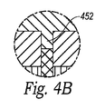
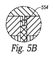
図4A、5A、6A、および7は、本開示の実施形態に従って構成される変換器アセンブリの図1Bに示される3−3’線(すなわち、方位角方向と平行)に沿った概略断面図である。図4B、5B、および6Bは、対応する部分図4A、5A、および6Aの拡大図である。 4A, 5A, 6A, and 7 are schematic cross-sectional views along the 3-3'line (ie, parallel to the azimuth direction) shown in FIG. 1B of the transducer assembly constructed according to embodiments of the present disclosure. be. 4B, 5B, and 6B are enlarged views of the corresponding partial views 4A, 5A, and 6A.
最初に図4を参照すると、変換器アセンブリ420は、第1の切溝342と、充填材348内に形成される溝452を有する、第2の切溝344と含む。溝452は、方位角方向において第1の切溝342および第2の切溝344の幅に実質的に類似する幅を有する。いくつかの実施形態では、第1の切溝342および第2の切溝344は、異なる溝深度を有することができる。図4Aおよび4Bの図示される実施形態では、溝452は、レンズ222と同一材料(例えば、RTV)で充填される。しかしながら、他の実施形態では、別の材料が、使用されてもよい。
First referring to FIG. 4, the
次に、図5を参照すると、変換器アセンブリ520は、第1の切溝342と、充填材348内に形成される部分または溝554を有する、第2の切溝とを含む。溝554は、方位角方向において第1の切溝342および第2の切溝344の幅より小さい幅(例えば、1/2幅、1/4幅、1/8幅)を有する。いくつかの実施形態では、第1の切溝342および第2の切溝344は、異なる溝深度を有することができる。図5Aおよび5Bの図示される実施形態では、溝554は、レンズ222と同一材料(例えば、RTV)で充填される。しかしながら、他の実施形態では、別の材料が、使用されてもよい。
Next, referring to FIG. 5, the
次に、図6を参照すると、超音波変換器アセンブリ620は、第1の切溝342と、充填材348内に形成される部分または溝656を有する、第2の切溝とを含む。溝656は、方位角方向において第1の切溝342および第2の切溝344の幅より小さい幅(例えば、1/2幅、1/4幅、1/8幅)を有する。いくつかの実施形態では、第1の切溝342および第2の切溝344は、異なる溝深度を有することができる。図5Aおよび5Bの図示される実施形態では、溝656は、レンズ222と同一材料(例えば、RTV)で充填される。しかしながら、他の実施形態では、別の材料が、使用されてもよい。
Next, referring to FIG. 6, the
ここで図7を参照すると、超音波変換器アセンブリ720は、第1の切溝342と、第2の充填材754(例えば、マイクロバルーンを備える複合材)の上方に第1の充填材752(例えば、ポリマー)を有する、第2の切溝とを含む。いくつかの実施形態では、溝は、図4A−6Bを参照して前述のように、第1の充填材752内に形成されることができる。
With reference to FIG. 7, the
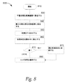
図8は、本開示の技術のある実施形態に従って超音波変換器アセンブリを構築するプロセス800のフロー図である。ブロック810では、プロセス800が開始する。ブロック830では、プロセス800は、接着剤(例えば、エポキシ、ポリマー)を使用して、変換器層(例えば、図2の変換器層230)の下側表面を不整合層の上側表面に接合する。ブロック840では、プロセス800は、第1の整合層を変換器層に接合し、1つまたはそれを上回る付加的整合層を第1の整合層に接合する。いくつかの実施形態では、プロセス800は、随意に、エポキシを使用して、不整合層(例えば、図2の不整合層234)の下側表面をバッキング層(例えば、図2のバッキング層240)の上側表面に接合することができる。ブロック850では、プロセス800は、1回またはそれを上回る切断を行い、1つまたはそれを上回る切溝(例えば、図3の第1の切溝342または第2の切溝344)を変換器アセンブリ内に形成する。ブロック860では、プロセス800は、ブロック850で形成される切溝の少なくとも一部に充填材(例えば、マイクロバルーンを備える充填材)を挿入する、または別様にそれで充填する。
FIG. 8 is a flow chart of
決定ブロック870では、プロセス800は、1つまたはそれを上回る溝がブロック860で形成される切溝の中に挿入される充填材内に形成されるべきかどうかを判定する。該当する場合、プロセス800は、ブロック875に進み、1つまたはそれを上回る切溝が、ブロック860で切溝の中に挿入される充填材内に形成される(例えば、図4Aおよび4Bの溝452、図5Aおよび5Bの溝554、および/または図6Aおよび6Bの溝656)。ブロック880では、レンズ材料(例えば、RTVまたは別の好適なレンズ材料)が、変換器アセンブリの正面(すなわち、最上整合層上)上に適用される。
In the determination block 870, the
本明細書の説明および請求項全体を通して別途文脈により明確に指定されない限り、「備える(comprise)」、「備えている(comprising)」、および同等物の単語は、排他的または網羅的な意味ではなく、包含的な意味(すなわち、例えば、「含むがこれに限定されない(including, but not limited to)」)の意味に解釈するものとする。本明細書で使用されるように、「接続された(connected)」、「結合された(coupled)」という用語またその任意の変形は、2つまたはそれを上回る要素間の直接的または間接的のいずれかの任意の接続または結合を意味する。そのような要素間の接続または結合は、物理的、論理的、またはその組み合わせであることができる。加えて、本願で使用されるとき、「本明細書における(herein)」、「上記(above)」、「下記(below)」という用語および同様の趣旨の用語は、本願全体を指すものであって、本願の任意の特定の部分を指すものではない。文脈が許す場合、単数形または複数形を使用した上の前述の発明を実施するための形態における用語はまた、それぞれ、複数または単数を含んでいてもよい。2つまたはそれを上回る項目のリストを指す「または(or)」という用語は、当該用語の以下の解釈の全てを網羅する。すなわち、当該リストの項目の任意のもの、当該リストの項目の全て、および当該リストの項目の任意の組み合せ。 Unless otherwise expressly specified in the context throughout the description and claims herein, the terms "comprise," "comprising," and equivalents are used in an exclusive or exhaustive sense. It shall be interpreted as an inclusive meaning (ie, for example, "inclusion, but not limited to"). As used herein, the terms "connected", "coupled" and any variations thereof are direct or indirect between two or more elements. Means any connection or join of any of. The connection or connection between such elements can be physical, logical, or a combination thereof. In addition, as used herein, the terms "herein", "above", "below" and similar terms refer to the entire application. It does not refer to any particular part of the present application. Where the context allows, the terms in the form for carrying out the above invention using the singular or plural may also include the plural or singular, respectively. The term "or", which refers to a list of two or more items, covers all of the following interpretations of the term. That is, any of the items in the list, all of the items in the list, and any combination of the items in the list.
本開示の技術の実施例の前述の発明を実施するための形態は、包括的なものではなく、かつ本開示の技術を上で開示した精密な形態に限定することを意図していない。本開示の技術の具体的実施例は、例証目的で前述されており、当業者が認識するであろうように、本開示の技術の範囲内で種々の均等な修正が可能である。 The embodiments of the techniques of the present disclosure for carrying out the aforementioned invention are not comprehensive and are not intended to limit the techniques of the present disclosure to the precise embodiments disclosed above. Specific examples of the techniques of the present disclosure have been described above for illustrative purposes and, as will be appreciated by those skilled in the art, various uniform modifications are possible within the scope of the techniques of the present disclosure.
本明細書に提供される本開示の技術の種々の例証および教示はまた、必ずしも前述のシステムではない他のシステムにも適用されることができる。前述の種々の実施例の要素および作用は、本開示の技術のさらなる実装を提供するように組み合わせられることができる。本開示の技術のいくつかの代替実装は、前述のそれらの実装に対する付加的要素を含んでもよいだけではなく、また、より少ない要素を含んでもよい。例えば、いくつかの実装では、本開示の技術に従って構成される変換器アセンブリは、3つより少ない整合層または4つまたはそれを上回る整合層を含んでもよい。他の実装では、変換器アセンブリは、不整合層を伴わずに本開示の技術に従って構成されることができる。 The various illustrations and teachings of the techniques of the present disclosure provided herein can also be applied to other systems that are not necessarily the systems described above. The elements and actions of the various embodiments described above can be combined to provide further implementation of the techniques of the present disclosure. Some alternative implementations of the techniques of the present disclosure may include not only additional elements to those implementations described above, but also fewer elements. For example, in some implementations, the transducer assembly constructed according to the techniques of the present disclosure may include less than three matching layers or four or more matching layers. In other implementations, the transducer assembly can be constructed according to the techniques of the present disclosure without an inconsistent layer.
本開示の技術に対するこれらのおよび他の変更は、前述の発明を実施するための形態に照らして行われることができる。前述の説明が本開示の技術のある実施例を説明し、想定される最良の形態を説明しているが、前述がいかに詳細に文書化されていようとも、本開示の技術は、多くの方法で実践されることができる。本システムの詳細は、その具体的実装においてかなり異なり得るが、依然として、本明細書に開示される本発明によって包含されている。前述のように、本開示の技術のある特徴または側面を説明する際に使用される特定の専門用語は、当該用語が関連付けられている本開示の技術の任意の具体的特性、特徴、または側面に制限されるように本明細書において再定義されていることを含意すると見なされるべきではない。一般に、以下の請求項で使用する用語は、前述の発明を実施するための形態の項が明示的に当該用語を定義しない限り、本発明を本明細書に開示する具体的実施例を限定するものと解釈すべきではない。 These and other modifications to the techniques of the present disclosure can be made in the light of embodiments for carrying out the invention described above. Although the aforementioned description describes some embodiments of the techniques of the present disclosure and describes the best possible embodiments, the techniques of the present disclosure can be used in many ways, no matter how detailed the statements may be. Can be practiced at. The details of the system may vary considerably in its concrete implementation, but are still incorporated by the invention disclosed herein. As mentioned above, the particular terminology used in describing certain features or aspects of the technology of the present disclosure is any specific property, feature, or aspect of the technology of the present disclosure to which the term is associated. It should not be considered to imply that it has been redefined herein to be limited to. In general, the terms used in the following claims limit specific embodiments that disclose the invention herein, unless the terms of the embodiments for carrying out the invention described above explicitly define the term. It should not be interpreted as a thing.
Claims (28)
超音波エネルギーを軸方向において放出するように構成される、変換器層と、
前記軸方向において前記変換器層の上にある、複数の整合層と、
前記複数の整合層の上にあるレンズと、
前記レンズから少なくとも前記複数の整合層の中に延在する複数の切溝であって、前記複数の切溝の各切溝は、少なくとも部分的に、マイクロバルーンまたはマイクロスフェアを備える第1の充填材で充填されると共に、前記各切溝は、前記レンズに隣接する前記複数の整合層の部分で前記各切溝の中の前記第1の充填材の中の溝を含み、前記溝は前記溝が含まれる前記各切溝の幅より狭い幅を有しかつ前記第1の充填材とは異なる第2の充填材で充填される、切溝と、
を備える、超音波変換器アセンブリ。 Ultrasonic transducer assembly
A transducer layer configured to emit ultrasonic energy in the axial direction, and
With a plurality of matching layers above the transducer layer in the axial direction,
With the lens on the plurality of matching layers,
A plurality of kerfs extending in at least the plurality of matching layers from the lens, the kerfs of said plurality of notch is at least partially, the first filling comprising microballoons or microspheres Each of the notches is filled with a material and includes a groove in the first filler in each of the notches at a portion of the plurality of matching layers adjacent to the lens, and the groove is said. A groove having a width narrower than the width of each of the grooves including the groove and being filled with a second filler different from the first filler.
Ultrasonic transducer assembly.
圧電層の上側表面を複数の整合層を備える整合層の下側表面に接合するステップと、
前記圧電層の下側表面を不整合層に接合するステップと、
前記整合層の中に延在する第1の複数の切溝を形成するステップと、
前記整合層、前記圧電層、および前記不整合層を通して延在する第2の複数の切溝を形成するステップであって、前記第1の複数の切溝の深度は、前記第2の複数の切溝の深度未満である、ステップと、
少なくとも部分的に、マイクロバルーンまたはマイクロスフェアを備える第1の充填材で前記第1の複数の切溝及び前記第2の複数の切溝の各切溝を充填するステップと、
前記各切溝の中の前記第1の充填材に溝を形成するステップと、
を含み、
レンズが、前記複数の整合層の上に形成され、
前記各切溝の中の前記第1の充填材に形成された前記溝は、前記レンズに隣接する前記複数の整合層の部分に位置し、
前記溝は前記溝が含まれる前記各切溝の幅より狭い幅を有しかつ前記第1の充填材とは異なる第2の充填材で充填され、
前記第1の複数の切溝及び前記第2の複数の切溝は、前記レンズから延びる、
を含む、方法。 How to build an ultrasonic transducer assembly
A step of joining the upper surface of the piezoelectric layer to the lower surface of the matching layer having a plurality of matching layers,
The step of joining the lower surface of the piezoelectric layer to the unmatched layer,
A step of forming a first plurality of grooves extending in the matching layer, and
A step of forming a second plurality of grooves extending through the matching layer, the piezoelectric layer, and the unmatched layer, wherein the depth of the first plurality of grooves is the second plurality of grooves. With steps that are less than the depth of the rift,
At least in part, a step of filling each of the first plurality of girders and the second plurality of girders with a first filler comprising microballoons or microspheres.
A step of forming a groove in the first filler in each of the cut grooves,
Including
A lens is formed on the plurality of matching layers and
The groove formed in the first filler in each of the cut grooves is located in a portion of the plurality of matching layers adjacent to the lens.
The groove has a width narrower than the width of each of the cut grooves including the groove and is filled with a second filler different from the first filler.
The first plurality of grooves and the second plurality of grooves extend from the lens.
Including methods.
超音波エネルギーを放出するように構成される複数の圧電変換器要素を備える、圧電層と、
前記圧電層の上にある、複数の整合層であって、Z-軸が、前記複数の整合層および前記圧電層を通して延在する、複数の整合層と、前記複数の整合層の上にあるレンズと、
前記レンズが少なくとも前記複数の整合層の中に延在する、複数の第1の切溝および複数の第2の切溝であって、前記第1の切溝は、前記Z-軸に対して第1の深度を有し、前記第2の切溝は、前記Z-軸に対して第2の深度を有し、前記第2の深度は、前記第1の深度を上回り、前記複数の第1の切溝及び前記複数の第2の切溝の各切溝は、少なくとも部分的に、マイクロバルーンまたはマイクロスフェアを備える第1の充填材で充填され、前記各切溝は、前記レンズに隣接する前記複数の整合層の部分で前記各切溝の中の前記第1の充填材の中の溝を含み、前記溝は、前記溝が含まれる前記各切溝の幅より狭い幅を有しかつ前記第1の充填材とは異なる第2の充填材で充填される、複数の第1の切溝および複数の第2の切溝と、
を備える、超音波変換器アセンブリ。 Ultrasonic transducer assembly
A piezoelectric layer with multiple piezoelectric transducer elements configured to emit ultrasonic energy,
A plurality of matching layers on the piezoelectric layer, the Z-axis extending through the plurality of matching layers and the piezoelectric layer, and on the plurality of matching layers and the plurality of matching layers. With the lens
A plurality of first grooves and a plurality of second grooves in which the lens extends into at least the plurality of matching layers, wherein the first groove is relative to the Z-axis. It has a first depth, the second groove has a second depth with respect to the Z-axis, the second depth exceeds the first depth, and the plurality of first depths. Each of the one gutter and the plurality of second gutters is at least partially filled with a first filler comprising microballoons or microspheres, each of which is adjacent to the lens. The portion of the plurality of matching layers includes a groove in the first filler in each of the cut grooves, and the groove has a width narrower than the width of each of the cut grooves including the groove. A plurality of first cut grooves and a plurality of second cut grooves, which are filled with a second filler different from the first filler.
Ultrasonic transducer assembly.
前記圧電層と前記バッキング層との間の不整合層であって、前記第2の切溝は、前記複数の整合層、前記圧電層、および前記不整合層を通して前記バッキング層の中に延在する、不整合層と、
をさらに備える、請求項18に記載の超音波変換器アセンブリ。 The backing layer under the piezoelectric layer and
An unmatched layer between the piezoelectric layer and the backing layer, the second groove extending into the backing layer through the plurality of matching layers, the piezoelectric layer, and the unmatched layer. With the inconsistent layer,
18. The ultrasonic transducer assembly according to claim 18.
前記各切溝は、前記方位角軸に対して第1の幅を有し、前記溝は、前記方位角軸に対して前記第1の幅未満の第2の幅を有する、請求項18に記載の超音波変換器アセンブリ。 The piezoelectric layer and the plurality of matching layers have a certain length extending along the azimuth axis.
Before SL each kerf has a first width with respect to the azimuth axis, the groove has a second width less than said first width to said azimuth axis, claim 18 The ultrasonic transducer assembly described in.
Applications Claiming Priority (3)
| Application Number | Priority Date | Filing Date | Title |
|---|---|---|---|
| US201562214185P | 2015-09-03 | 2015-09-03 | |
| US62/214,185 | 2015-09-03 | ||
| PCT/US2016/050171 WO2017040979A1 (en) | 2015-09-03 | 2016-09-02 | Ultrasound transducer assembly |
Publications (3)
| Publication Number | Publication Date |
|---|---|
| JP2018532307A JP2018532307A (en) | 2018-11-01 |
| JP2018532307A5 JP2018532307A5 (en) | 2019-10-10 |
| JP6911013B2 true JP6911013B2 (en) | 2021-07-28 |
Family
ID=58188539
Family Applications (1)
| Application Number | Title | Priority Date | Filing Date |
|---|---|---|---|
| JP2018511677A Active JP6911013B2 (en) | 2015-09-03 | 2016-09-02 | Ultrasonic transducer assembly |
Country Status (6)
| Country | Link |
|---|---|
| US (2) | US10716542B2 (en) |
| EP (2) | EP3344147B1 (en) |
| JP (1) | JP6911013B2 (en) |
| KR (1) | KR102633430B1 (en) |
| CN (1) | CN107920797B (en) |
| WO (1) | WO2017040979A1 (en) |
Families Citing this family (13)
| Publication number | Priority date | Publication date | Assignee | Title |
|---|---|---|---|---|
| US9808830B2 (en) * | 2013-12-27 | 2017-11-07 | General Electric Company | Ultrasound transducer and ultrasound imaging system with a variable thickness dematching layer |
| KR20170090304A (en) * | 2016-01-28 | 2017-08-07 | 삼성메디슨 주식회사 | Ultrasonic transducer and ultrasonic probe including the same |
| USD831219S1 (en) * | 2017-07-31 | 2018-10-16 | Edan Instruments, Inc. | Transducer |
| US11678865B2 (en) * | 2017-12-29 | 2023-06-20 | Fujifilm Sonosite, Inc. | High frequency ultrasound transducer |
| JP2021533707A (en) * | 2018-07-31 | 2021-12-02 | レゾナント・アコースティックス・インターナショナル・インコーポレーテッド | Ultrasonic transducer |
| CN109530196B (en) * | 2018-11-28 | 2023-10-27 | 深圳先进技术研究院 | Transducer assembly and method of making the same |
| WO2020107283A1 (en) * | 2018-11-28 | 2020-06-04 | 深圳先进技术研究院 | Transducer assembly, and manufacturing method for same |
| US11583259B2 (en) * | 2018-12-19 | 2023-02-21 | Fujifilm Sonosite, Inc. | Thermal conductive layer for transducer face temperature reduction |
| US20200289093A1 (en) * | 2019-03-15 | 2020-09-17 | EchoNous, Inc. | Ultrasound transducer assembly having low viscosity kerf fill material |
| KR20210136133A (en) | 2019-03-25 | 2021-11-16 | 엑소 이미징, 인크. | handheld ultrasound imaging device |
| EP4062128A4 (en) * | 2019-11-18 | 2023-11-22 | Resonant Acoustics International Inc. | Ultrasonic transducers, backing structures and related methods |
| JP2021136675A (en) * | 2020-02-28 | 2021-09-13 | 学校法人早稲田大学 | Piezoelectric device |
| CN113180727B (en) * | 2021-03-29 | 2023-03-03 | 聚融医疗科技(杭州)有限公司 | Ultrasonic transducer with freely selectable joint filling material and preparation method thereof |
Family Cites Families (36)
| Publication number | Priority date | Publication date | Assignee | Title |
|---|---|---|---|---|
| JPS5315486U (en) | 1976-07-21 | 1978-02-08 | ||
| JPS6029731B2 (en) * | 1977-04-26 | 1985-07-12 | 旭化成株式会社 | Polycondensation method |
| JPS5925500A (en) | 1982-08-02 | 1984-02-09 | Matsushita Electric Ind Co Ltd | Production of ultrasonic wave probe |
| JPS6139700A (en) | 1984-07-30 | 1986-02-25 | Shimadzu Corp | Manufacture of ultrasonic probe |
| JPS6139700U (en) | 1984-08-15 | 1986-03-13 | 三菱重工業株式会社 | Engine room air supply system |
| EP0210723B1 (en) | 1985-05-20 | 1991-04-10 | Matsushita Electric Industrial Co., Ltd. | Ultrasonic probe |
| JP2794720B2 (en) | 1988-08-23 | 1998-09-10 | 松下電器産業株式会社 | Composite piezoelectric vibrator |
| US5311095A (en) * | 1992-05-14 | 1994-05-10 | Duke University | Ultrasonic transducer array |
| US5553035A (en) | 1993-06-15 | 1996-09-03 | Hewlett-Packard Company | Method of forming integral transducer and impedance matching layers |
| US5648942A (en) * | 1995-10-13 | 1997-07-15 | Advanced Technology Laboratories, Inc. | Acoustic backing with integral conductors for an ultrasonic transducer |
| JP3673035B2 (en) * | 1996-10-25 | 2005-07-20 | 株式会社東芝 | Ultrasonic transducer |
| US6359375B1 (en) | 1998-05-06 | 2002-03-19 | Siemens Medical Solutions Usa, Inc. | Method to build a high bandwidth, low crosstalk, low EM noise transducer |
| JP2003175036A (en) * | 2001-12-11 | 2003-06-24 | Aloka Co Ltd | Ultrasonic probe and ultrasonic diagnostic apparatus |
| JP3908595B2 (en) * | 2002-05-17 | 2007-04-25 | アロカ株式会社 | Ultrasonic probe |
| US20040190377A1 (en) * | 2003-03-06 | 2004-09-30 | Lewandowski Robert Stephen | Method and means for isolating elements of a sensor array |
| US7368852B2 (en) | 2003-08-22 | 2008-05-06 | Siemens Medical Solutions Usa, Inc. | Electrically conductive matching layers and methods |
| US7285897B2 (en) * | 2003-12-31 | 2007-10-23 | General Electric Company | Curved micromachined ultrasonic transducer arrays and related methods of manufacture |
| US20070222339A1 (en) * | 2004-04-20 | 2007-09-27 | Mark Lukacs | Arrayed ultrasonic transducer |
| JP2005340903A (en) * | 2004-05-24 | 2005-12-08 | Olympus Corp | Ultrasonic wave transducer and its manufacturing method |
| US20060028099A1 (en) | 2004-08-05 | 2006-02-09 | Frey Gregg W | Composite acoustic matching layer |
| JP4933392B2 (en) * | 2007-04-02 | 2012-05-16 | 富士フイルム株式会社 | Ultrasonic probe and manufacturing method thereof |
| JP5002402B2 (en) | 2007-10-03 | 2012-08-15 | 株式会社東芝 | Ultrasonic probe and ultrasonic diagnostic apparatus |
| US8378557B2 (en) * | 2010-07-09 | 2013-02-19 | General Electric Company | Thermal transfer and acoustic matching layers for ultrasound transducer |
| JP5643667B2 (en) | 2011-01-28 | 2014-12-17 | 株式会社東芝 | Ultrasonic transducer, ultrasonic probe, and method of manufacturing ultrasonic transducer |
| JP5468564B2 (en) * | 2011-03-30 | 2014-04-09 | 富士フイルム株式会社 | Ultrasonic probe and ultrasonic diagnostic apparatus |
| JP6548201B2 (en) * | 2011-09-16 | 2019-07-24 | ゼネラル・エレクトリック・カンパニイ | Heat transfer and acoustic matching layer for ultrasonic transducers |
| KR101269459B1 (en) * | 2011-12-13 | 2013-05-30 | 삼성전자주식회사 | Ultrasound probe and manufacturing method thereof |
| KR101477544B1 (en) * | 2012-01-02 | 2014-12-31 | 삼성전자주식회사 | Ultrasonic transducer, ultrasonic probe, and ultrasound image diagnosis apparatus |
| WO2013114968A1 (en) * | 2012-01-30 | 2013-08-08 | オリンパスメディカルシステムズ株式会社 | Ultrasonic vibrator array, method for manufacturing ultrasonic vibrator array, and ultrasonic endoscope |
| JP6029731B2 (en) | 2012-02-07 | 2016-11-24 | 富士フイルム株式会社 | Ultrasonic probe |
| JP5924298B2 (en) * | 2013-03-19 | 2016-05-25 | コニカミノルタ株式会社 | Ultrasonic probe and ultrasonic diagnostic imaging apparatus |
| JP2014188009A (en) * | 2013-03-26 | 2014-10-06 | Konica Minolta Inc | Ultrasonic probe, ultrasonic image diagnostic apparatus, and method of manufacturing ultrasonic probe |
| JP6214333B2 (en) * | 2013-10-23 | 2017-10-18 | 三菱鉛筆株式会社 | Acoustic matching layer and manufacturing method thereof |
| JP5665948B1 (en) * | 2013-11-14 | 2015-02-04 | 株式会社フジクラ | Cooling structure for portable electronic devices |
| WO2015083551A1 (en) | 2013-12-02 | 2015-06-11 | 株式会社東芝 | Leak suppression device, leak suppression system and leak suppression program |
| JP6641723B2 (en) | 2015-05-08 | 2020-02-05 | コニカミノルタ株式会社 | Ultrasonic transducer and manufacturing method thereof, ultrasonic probe, and ultrasonic imaging apparatus |
-
2016
- 2016-09-02 US US15/256,029 patent/US10716542B2/en active Active
- 2016-09-02 EP EP16843099.9A patent/EP3344147B1/en active Active
- 2016-09-02 CN CN201680049560.3A patent/CN107920797B/en active Active
- 2016-09-02 KR KR1020187005215A patent/KR102633430B1/en active IP Right Grant
- 2016-09-02 WO PCT/US2016/050171 patent/WO2017040979A1/en active Application Filing
- 2016-09-02 EP EP23163129.2A patent/EP4219026A1/en active Pending
- 2016-09-02 JP JP2018511677A patent/JP6911013B2/en active Active
-
2020
- 2020-07-20 US US16/933,822 patent/US11890140B2/en active Active
Also Published As
| Publication number | Publication date |
|---|---|
| US20200345328A1 (en) | 2020-11-05 |
| EP4219026A1 (en) | 2023-08-02 |
| EP3344147A1 (en) | 2018-07-11 |
| EP3344147A4 (en) | 2019-05-22 |
| CN107920797A (en) | 2018-04-17 |
| CN107920797B (en) | 2021-02-12 |
| US10716542B2 (en) | 2020-07-21 |
| US11890140B2 (en) | 2024-02-06 |
| KR20180038467A (en) | 2018-04-16 |
| WO2017040979A1 (en) | 2017-03-09 |
| KR102633430B1 (en) | 2024-02-02 |
| JP2018532307A (en) | 2018-11-01 |
| EP3344147B1 (en) | 2023-11-01 |
| US20170065253A1 (en) | 2017-03-09 |
Similar Documents
| Publication | Publication Date | Title |
|---|---|---|
| JP6911013B2 (en) | Ultrasonic transducer assembly | |
| US20120007471A1 (en) | Thermal Transfer and Acoustic Matching Layers for Ultrasound Transducer | |
| EP2686117B1 (en) | High porosity acoustic backing with high thermal conductivity for ultrasound transducer array | |
| JP6373024B2 (en) | Acoustic lens for micromachined ultrasonic transducers | |
| US8378557B2 (en) | Thermal transfer and acoustic matching layers for ultrasound transducer | |
| JP5865873B2 (en) | Ultrasonic probe | |
| CN111465455B (en) | High frequency ultrasonic transducer | |
| KR102357211B1 (en) | Composite acoustic absorber for ultrasound transducer array | |
| CN102989654A (en) | Thermal transfer and acoustic matching layers for ultrasound transducer | |
| US9799818B2 (en) | Ultrasound probe with heat collecting portion | |
| US11691177B2 (en) | Ultrasound probe with acoustic amplifier | |
| JP5358078B2 (en) | Ultrasonic probe | |
| EP3808277B1 (en) | Ultrasound transducer, ultrasonic probe, and ultrasonic detection apparatus | |
| US20200289093A1 (en) | Ultrasound transducer assembly having low viscosity kerf fill material | |
| US9566612B2 (en) | Ultrasonic probe | |
| CN102594278A (en) | Combined piezoelectric vibrator and preparation method thereof | |
| JP2012249777A5 (en) | ||
| US20050225211A1 (en) | Matching layer systems and methods for ultrasound transducers | |
| US7358645B2 (en) | Backing, transducer array and method for thermal survival | |
| JP3816596B2 (en) | Ultrasonic transducer and method for manufacturing the same | |
| JP5322419B2 (en) | Ultrasonic probe and piezoelectric vibrator | |
| WO2023098736A1 (en) | Ultrasonic transducer and method for preparing matching layer | |
| KR20160096935A (en) | Ultrasonic Transducer for Improving Accoustic and Heat Characteristic | |
| CN111192954A (en) | Piezoelectric ceramic composite material structure applied to energy conversion device | |
| CN115414068A (en) | Matching layer for ultrasonic transducer and preparation method |
Legal Events
| Date | Code | Title | Description |
|---|---|---|---|
| RD03 | Notification of appointment of power of attorney |
Free format text: JAPANESE INTERMEDIATE CODE: A7423 Effective date: 20180522 |
|
| RD04 | Notification of resignation of power of attorney |
Free format text: JAPANESE INTERMEDIATE CODE: A7424 Effective date: 20180530 |
|
| A521 | Request for written amendment filed |
Free format text: JAPANESE INTERMEDIATE CODE: A523 Effective date: 20190827 |
|
| A621 | Written request for application examination |
Free format text: JAPANESE INTERMEDIATE CODE: A621 Effective date: 20190827 |
|
| A131 | Notification of reasons for refusal |
Free format text: JAPANESE INTERMEDIATE CODE: A131 Effective date: 20200929 |
|
| A521 | Request for written amendment filed |
Free format text: JAPANESE INTERMEDIATE CODE: A523 Effective date: 20201228 |
|
| TRDD | Decision of grant or rejection written | ||
| A01 | Written decision to grant a patent or to grant a registration (utility model) |
Free format text: JAPANESE INTERMEDIATE CODE: A01 Effective date: 20210608 |
|
| A61 | First payment of annual fees (during grant procedure) |
Free format text: JAPANESE INTERMEDIATE CODE: A61 Effective date: 20210707 |
|
| R150 | Certificate of patent or registration of utility model |
Ref document number: 6911013 Country of ref document: JP Free format text: JAPANESE INTERMEDIATE CODE: R150 |