EP3343691B1 - Battery module - Google Patents
Battery module Download PDFInfo
- Publication number
- EP3343691B1 EP3343691B1 EP16849021.7A EP16849021A EP3343691B1 EP 3343691 B1 EP3343691 B1 EP 3343691B1 EP 16849021 A EP16849021 A EP 16849021A EP 3343691 B1 EP3343691 B1 EP 3343691B1
- Authority
- EP
- European Patent Office
- Prior art keywords
- cover
- side cover
- battery module
- cooling plate
- welded
- Prior art date
- Legal status (The legal status is an assumption and is not a legal conclusion. Google has not performed a legal analysis and makes no representation as to the accuracy of the status listed.)
- Active
Links
- 238000001816 cooling Methods 0.000 claims description 147
- 238000003466 welding Methods 0.000 claims description 72
- 238000000034 method Methods 0.000 claims description 46
- 238000003756 stirring Methods 0.000 claims description 28
- 239000000463 material Substances 0.000 claims description 22
- 229910000831 Steel Inorganic materials 0.000 claims description 9
- 239000010959 steel Substances 0.000 claims description 9
- 230000033001 locomotion Effects 0.000 claims description 5
- 229910052782 aluminium Inorganic materials 0.000 claims description 4
- XAGFODPZIPBFFR-UHFFFAOYSA-N aluminium Chemical compound [Al] XAGFODPZIPBFFR-UHFFFAOYSA-N 0.000 claims description 4
- 239000011247 coating layer Substances 0.000 claims description 4
- 238000003780 insertion Methods 0.000 claims description 4
- 230000037431 insertion Effects 0.000 claims description 4
- 238000005304 joining Methods 0.000 claims description 3
- 230000008569 process Effects 0.000 description 24
- 238000007789 sealing Methods 0.000 description 21
- 230000008878 coupling Effects 0.000 description 11
- 238000010168 coupling process Methods 0.000 description 11
- 238000005859 coupling reaction Methods 0.000 description 11
- 239000000126 substance Substances 0.000 description 10
- 239000000523 sample Substances 0.000 description 9
- 239000007769 metal material Substances 0.000 description 8
- WHXSMMKQMYFTQS-UHFFFAOYSA-N Lithium Chemical compound [Li] WHXSMMKQMYFTQS-UHFFFAOYSA-N 0.000 description 7
- RKTYLMNFRDHKIL-UHFFFAOYSA-N copper;5,10,15,20-tetraphenylporphyrin-22,24-diide Chemical group [Cu+2].C1=CC(C(=C2C=CC([N-]2)=C(C=2C=CC=CC=2)C=2C=CC(N=2)=C(C=2C=CC=CC=2)C2=CC=C3[N-]2)C=2C=CC=CC=2)=NC1=C3C1=CC=CC=C1 RKTYLMNFRDHKIL-UHFFFAOYSA-N 0.000 description 7
- 229910052744 lithium Inorganic materials 0.000 description 7
- 239000010953 base metal Substances 0.000 description 4
- 239000010410 layer Substances 0.000 description 4
- 238000009751 slip forming Methods 0.000 description 4
- 238000004519 manufacturing process Methods 0.000 description 3
- PXHVJJICTQNCMI-UHFFFAOYSA-N Nickel Chemical compound [Ni] PXHVJJICTQNCMI-UHFFFAOYSA-N 0.000 description 2
- 230000004308 accommodation Effects 0.000 description 2
- 239000012790 adhesive layer Substances 0.000 description 2
- 239000012809 cooling fluid Substances 0.000 description 2
- 230000003247 decreasing effect Effects 0.000 description 2
- 239000003792 electrolyte Substances 0.000 description 2
- 230000004927 fusion Effects 0.000 description 2
- 229910000765 intermetallic Inorganic materials 0.000 description 2
- 229910052751 metal Inorganic materials 0.000 description 2
- 239000002184 metal Substances 0.000 description 2
- 239000007773 negative electrode material Substances 0.000 description 2
- 239000007774 positive electrode material Substances 0.000 description 2
- 239000004642 Polyimide Substances 0.000 description 1
- OJIJEKBXJYRIBZ-UHFFFAOYSA-N cadmium nickel Chemical compound [Ni].[Cd] OJIJEKBXJYRIBZ-UHFFFAOYSA-N 0.000 description 1
- 239000003575 carbonaceous material Substances 0.000 description 1
- 229910010293 ceramic material Inorganic materials 0.000 description 1
- 238000000576 coating method Methods 0.000 description 1
- 150000001875 compounds Chemical class 0.000 description 1
- 239000004020 conductor Substances 0.000 description 1
- 230000001419 dependent effect Effects 0.000 description 1
- 239000000428 dust Substances 0.000 description 1
- 230000000694 effects Effects 0.000 description 1
- 239000008151 electrolyte solution Substances 0.000 description 1
- 239000000835 fiber Substances 0.000 description 1
- 230000006870 function Effects 0.000 description 1
- 239000011491 glass wool Substances 0.000 description 1
- 229920006015 heat resistant resin Polymers 0.000 description 1
- 239000011810 insulating material Substances 0.000 description 1
- 238000009413 insulation Methods 0.000 description 1
- 238000002844 melting Methods 0.000 description 1
- 230000008018 melting Effects 0.000 description 1
- 230000003446 memory effect Effects 0.000 description 1
- 229910052987 metal hydride Inorganic materials 0.000 description 1
- 239000011490 mineral wool Substances 0.000 description 1
- 238000012986 modification Methods 0.000 description 1
- 230000004048 modification Effects 0.000 description 1
- 229910052759 nickel Inorganic materials 0.000 description 1
- QELJHCBNGDEXLD-UHFFFAOYSA-N nickel zinc Chemical compound [Ni].[Zn] QELJHCBNGDEXLD-UHFFFAOYSA-N 0.000 description 1
- 238000007500 overflow downdraw method Methods 0.000 description 1
- 230000002093 peripheral effect Effects 0.000 description 1
- 229920001721 polyimide Polymers 0.000 description 1
- 230000002787 reinforcement Effects 0.000 description 1
- 239000000243 solution Substances 0.000 description 1
- 238000003860 storage Methods 0.000 description 1
- XLYOFNOQVPJJNP-UHFFFAOYSA-N water Substances O XLYOFNOQVPJJNP-UHFFFAOYSA-N 0.000 description 1
Images


Classifications
-
- H—ELECTRICITY
- H01—ELECTRIC ELEMENTS
- H01M—PROCESSES OR MEANS, e.g. BATTERIES, FOR THE DIRECT CONVERSION OF CHEMICAL ENERGY INTO ELECTRICAL ENERGY
- H01M10/00—Secondary cells; Manufacture thereof
- H01M10/60—Heating or cooling; Temperature control
- H01M10/65—Means for temperature control structurally associated with the cells
- H01M10/655—Solid structures for heat exchange or heat conduction
- H01M10/6554—Rods or plates
-
- B—PERFORMING OPERATIONS; TRANSPORTING
- B60—VEHICLES IN GENERAL
- B60L—PROPULSION OF ELECTRICALLY-PROPELLED VEHICLES; SUPPLYING ELECTRIC POWER FOR AUXILIARY EQUIPMENT OF ELECTRICALLY-PROPELLED VEHICLES; ELECTRODYNAMIC BRAKE SYSTEMS FOR VEHICLES IN GENERAL; MAGNETIC SUSPENSION OR LEVITATION FOR VEHICLES; MONITORING OPERATING VARIABLES OF ELECTRICALLY-PROPELLED VEHICLES; ELECTRIC SAFETY DEVICES FOR ELECTRICALLY-PROPELLED VEHICLES
- B60L50/00—Electric propulsion with power supplied within the vehicle
- B60L50/50—Electric propulsion with power supplied within the vehicle using propulsion power supplied by batteries or fuel cells
- B60L50/60—Electric propulsion with power supplied within the vehicle using propulsion power supplied by batteries or fuel cells using power supplied by batteries
- B60L50/64—Constructional details of batteries specially adapted for electric vehicles
-
- B—PERFORMING OPERATIONS; TRANSPORTING
- B60—VEHICLES IN GENERAL
- B60L—PROPULSION OF ELECTRICALLY-PROPELLED VEHICLES; SUPPLYING ELECTRIC POWER FOR AUXILIARY EQUIPMENT OF ELECTRICALLY-PROPELLED VEHICLES; ELECTRODYNAMIC BRAKE SYSTEMS FOR VEHICLES IN GENERAL; MAGNETIC SUSPENSION OR LEVITATION FOR VEHICLES; MONITORING OPERATING VARIABLES OF ELECTRICALLY-PROPELLED VEHICLES; ELECTRIC SAFETY DEVICES FOR ELECTRICALLY-PROPELLED VEHICLES
- B60L58/00—Methods or circuit arrangements for monitoring or controlling batteries or fuel cells, specially adapted for electric vehicles
- B60L58/10—Methods or circuit arrangements for monitoring or controlling batteries or fuel cells, specially adapted for electric vehicles for monitoring or controlling batteries
- B60L58/24—Methods or circuit arrangements for monitoring or controlling batteries or fuel cells, specially adapted for electric vehicles for monitoring or controlling batteries for controlling the temperature of batteries
- B60L58/26—Methods or circuit arrangements for monitoring or controlling batteries or fuel cells, specially adapted for electric vehicles for monitoring or controlling batteries for controlling the temperature of batteries by cooling
-
- H—ELECTRICITY
- H01—ELECTRIC ELEMENTS
- H01M—PROCESSES OR MEANS, e.g. BATTERIES, FOR THE DIRECT CONVERSION OF CHEMICAL ENERGY INTO ELECTRICAL ENERGY
- H01M10/00—Secondary cells; Manufacture thereof
- H01M10/60—Heating or cooling; Temperature control
- H01M10/61—Types of temperature control
- H01M10/613—Cooling or keeping cold
-
- H—ELECTRICITY
- H01—ELECTRIC ELEMENTS
- H01M—PROCESSES OR MEANS, e.g. BATTERIES, FOR THE DIRECT CONVERSION OF CHEMICAL ENERGY INTO ELECTRICAL ENERGY
- H01M10/00—Secondary cells; Manufacture thereof
- H01M10/60—Heating or cooling; Temperature control
- H01M10/65—Means for temperature control structurally associated with the cells
- H01M10/658—Means for temperature control structurally associated with the cells by thermal insulation or shielding
-
- H—ELECTRICITY
- H01—ELECTRIC ELEMENTS
- H01M—PROCESSES OR MEANS, e.g. BATTERIES, FOR THE DIRECT CONVERSION OF CHEMICAL ENERGY INTO ELECTRICAL ENERGY
- H01M50/00—Constructional details or processes of manufacture of the non-active parts of electrochemical cells other than fuel cells, e.g. hybrid cells
- H01M50/20—Mountings; Secondary casings or frames; Racks, modules or packs; Suspension devices; Shock absorbers; Transport or carrying devices; Holders
- H01M50/204—Racks, modules or packs for multiple batteries or multiple cells
- H01M50/207—Racks, modules or packs for multiple batteries or multiple cells characterised by their shape
- H01M50/209—Racks, modules or packs for multiple batteries or multiple cells characterised by their shape adapted for prismatic or rectangular cells
-
- H—ELECTRICITY
- H01—ELECTRIC ELEMENTS
- H01M—PROCESSES OR MEANS, e.g. BATTERIES, FOR THE DIRECT CONVERSION OF CHEMICAL ENERGY INTO ELECTRICAL ENERGY
- H01M50/00—Constructional details or processes of manufacture of the non-active parts of electrochemical cells other than fuel cells, e.g. hybrid cells
- H01M50/20—Mountings; Secondary casings or frames; Racks, modules or packs; Suspension devices; Shock absorbers; Transport or carrying devices; Holders
- H01M50/204—Racks, modules or packs for multiple batteries or multiple cells
- H01M50/207—Racks, modules or packs for multiple batteries or multiple cells characterised by their shape
- H01M50/211—Racks, modules or packs for multiple batteries or multiple cells characterised by their shape adapted for pouch cells
-
- H—ELECTRICITY
- H01—ELECTRIC ELEMENTS
- H01M—PROCESSES OR MEANS, e.g. BATTERIES, FOR THE DIRECT CONVERSION OF CHEMICAL ENERGY INTO ELECTRICAL ENERGY
- H01M50/00—Constructional details or processes of manufacture of the non-active parts of electrochemical cells other than fuel cells, e.g. hybrid cells
- H01M50/20—Mountings; Secondary casings or frames; Racks, modules or packs; Suspension devices; Shock absorbers; Transport or carrying devices; Holders
- H01M50/218—Mountings; Secondary casings or frames; Racks, modules or packs; Suspension devices; Shock absorbers; Transport or carrying devices; Holders characterised by the material
- H01M50/22—Mountings; Secondary casings or frames; Racks, modules or packs; Suspension devices; Shock absorbers; Transport or carrying devices; Holders characterised by the material of the casings or racks
- H01M50/222—Inorganic material
- H01M50/224—Metals
-
- H—ELECTRICITY
- H01—ELECTRIC ELEMENTS
- H01M—PROCESSES OR MEANS, e.g. BATTERIES, FOR THE DIRECT CONVERSION OF CHEMICAL ENERGY INTO ELECTRICAL ENERGY
- H01M50/00—Constructional details or processes of manufacture of the non-active parts of electrochemical cells other than fuel cells, e.g. hybrid cells
- H01M50/20—Mountings; Secondary casings or frames; Racks, modules or packs; Suspension devices; Shock absorbers; Transport or carrying devices; Holders
- H01M50/218—Mountings; Secondary casings or frames; Racks, modules or packs; Suspension devices; Shock absorbers; Transport or carrying devices; Holders characterised by the material
- H01M50/22—Mountings; Secondary casings or frames; Racks, modules or packs; Suspension devices; Shock absorbers; Transport or carrying devices; Holders characterised by the material of the casings or racks
- H01M50/231—Mountings; Secondary casings or frames; Racks, modules or packs; Suspension devices; Shock absorbers; Transport or carrying devices; Holders characterised by the material of the casings or racks having a layered structure
-
- H—ELECTRICITY
- H01—ELECTRIC ELEMENTS
- H01M—PROCESSES OR MEANS, e.g. BATTERIES, FOR THE DIRECT CONVERSION OF CHEMICAL ENERGY INTO ELECTRICAL ENERGY
- H01M50/00—Constructional details or processes of manufacture of the non-active parts of electrochemical cells other than fuel cells, e.g. hybrid cells
- H01M50/20—Mountings; Secondary casings or frames; Racks, modules or packs; Suspension devices; Shock absorbers; Transport or carrying devices; Holders
- H01M50/233—Mountings; Secondary casings or frames; Racks, modules or packs; Suspension devices; Shock absorbers; Transport or carrying devices; Holders characterised by physical properties of casings or racks, e.g. dimensions
-
- H—ELECTRICITY
- H01—ELECTRIC ELEMENTS
- H01M—PROCESSES OR MEANS, e.g. BATTERIES, FOR THE DIRECT CONVERSION OF CHEMICAL ENERGY INTO ELECTRICAL ENERGY
- H01M50/00—Constructional details or processes of manufacture of the non-active parts of electrochemical cells other than fuel cells, e.g. hybrid cells
- H01M50/20—Mountings; Secondary casings or frames; Racks, modules or packs; Suspension devices; Shock absorbers; Transport or carrying devices; Holders
- H01M50/249—Mountings; Secondary casings or frames; Racks, modules or packs; Suspension devices; Shock absorbers; Transport or carrying devices; Holders specially adapted for aircraft or vehicles, e.g. cars or trains
-
- H—ELECTRICITY
- H01—ELECTRIC ELEMENTS
- H01M—PROCESSES OR MEANS, e.g. BATTERIES, FOR THE DIRECT CONVERSION OF CHEMICAL ENERGY INTO ELECTRICAL ENERGY
- H01M50/00—Constructional details or processes of manufacture of the non-active parts of electrochemical cells other than fuel cells, e.g. hybrid cells
- H01M50/20—Mountings; Secondary casings or frames; Racks, modules or packs; Suspension devices; Shock absorbers; Transport or carrying devices; Holders
- H01M50/258—Modular batteries; Casings provided with means for assembling
-
- H—ELECTRICITY
- H01—ELECTRIC ELEMENTS
- H01M—PROCESSES OR MEANS, e.g. BATTERIES, FOR THE DIRECT CONVERSION OF CHEMICAL ENERGY INTO ELECTRICAL ENERGY
- H01M50/00—Constructional details or processes of manufacture of the non-active parts of electrochemical cells other than fuel cells, e.g. hybrid cells
- H01M50/20—Mountings; Secondary casings or frames; Racks, modules or packs; Suspension devices; Shock absorbers; Transport or carrying devices; Holders
- H01M50/262—Mountings; Secondary casings or frames; Racks, modules or packs; Suspension devices; Shock absorbers; Transport or carrying devices; Holders with fastening means, e.g. locks
-
- H—ELECTRICITY
- H01—ELECTRIC ELEMENTS
- H01M—PROCESSES OR MEANS, e.g. BATTERIES, FOR THE DIRECT CONVERSION OF CHEMICAL ENERGY INTO ELECTRICAL ENERGY
- H01M50/00—Constructional details or processes of manufacture of the non-active parts of electrochemical cells other than fuel cells, e.g. hybrid cells
- H01M50/20—Mountings; Secondary casings or frames; Racks, modules or packs; Suspension devices; Shock absorbers; Transport or carrying devices; Holders
- H01M50/271—Lids or covers for the racks or secondary casings
- H01M50/273—Lids or covers for the racks or secondary casings characterised by the material
- H01M50/276—Inorganic material
-
- H—ELECTRICITY
- H01—ELECTRIC ELEMENTS
- H01M—PROCESSES OR MEANS, e.g. BATTERIES, FOR THE DIRECT CONVERSION OF CHEMICAL ENERGY INTO ELECTRICAL ENERGY
- H01M10/00—Secondary cells; Manufacture thereof
- H01M10/60—Heating or cooling; Temperature control
- H01M10/62—Heating or cooling; Temperature control specially adapted for specific applications
- H01M10/625—Vehicles
-
- H—ELECTRICITY
- H01—ELECTRIC ELEMENTS
- H01M—PROCESSES OR MEANS, e.g. BATTERIES, FOR THE DIRECT CONVERSION OF CHEMICAL ENERGY INTO ELECTRICAL ENERGY
- H01M2220/00—Batteries for particular applications
- H01M2220/20—Batteries in motive systems, e.g. vehicle, ship, plane
-
- Y—GENERAL TAGGING OF NEW TECHNOLOGICAL DEVELOPMENTS; GENERAL TAGGING OF CROSS-SECTIONAL TECHNOLOGIES SPANNING OVER SEVERAL SECTIONS OF THE IPC; TECHNICAL SUBJECTS COVERED BY FORMER USPC CROSS-REFERENCE ART COLLECTIONS [XRACs] AND DIGESTS
- Y02—TECHNOLOGIES OR APPLICATIONS FOR MITIGATION OR ADAPTATION AGAINST CLIMATE CHANGE
- Y02E—REDUCTION OF GREENHOUSE GAS [GHG] EMISSIONS, RELATED TO ENERGY GENERATION, TRANSMISSION OR DISTRIBUTION
- Y02E60/00—Enabling technologies; Technologies with a potential or indirect contribution to GHG emissions mitigation
- Y02E60/10—Energy storage using batteries
Definitions
- the present disclosure relates to a battery module having high processability, high sealability, and fewer components, and a battery pack including the battery module, and an automobile including the battery module.
- lithium secondary cells examples include nickel-cadmium cells, nickel-metal hydride cells, nickel-zinc cells, and lithium secondary cells.
- lithium secondary cells are freely rechargeable because of having substantially no memory effect compared with nickel-based secondary cells, and have a very low self-discharge rate and high energy density. Owing to these merits, there has been high interest in lithium secondary cells.
- lithium secondary cells use a lithium-based oxide as a positive electrode active material and a carbonaceous material as a negative electrode active material.
- a lithium secondary cell may include: an electrode assembly in which a positive electrode plate coated with such a positive electrode active material and a negative electrode plate coated with such a negative electrode active material are disposed with a separator therebetween; and a case in which the electrode assembly and an electrolytic solution are sealed.
- lithium secondary cells may be classified into a can type in which an electrode assembly is accommodated in a metal can, and a pouch type in which an electrode assembly is accommodated in a pouch formed of an aluminum laminate sheet.
- the mechanical strength that is, rigidity of a battery module including a plurality of pouch-type secondary cells as described above should be equal to or greater than a certain value so that the battery module may not be broken by external impacts, vibrations, or the like.
- battery modules having high assemblability and fewer components are preferable to increasing productivity.
- the present disclosure is designed to solve the problems of the related art, and therefore the present disclosure is directed to providing a battery module having stable strength and rigidity, high sealability and assemblability, and improved productivity, and an automobile including the battery module.
- the present disclosure provides a battery module according to claim 1. Additional features are disclosed in dependent claims.
- the present disclosure provides a battery pack including the battery module.
- the present disclosure provides an automobile including the battery module.
- the battery module may have high sealability.
- the sealability of the battery module may be stably maintained even at a high pressure.
- the rigidity of the battery module may be stably guaranteed.
- the battery module may be easily assembled and high processability.
- the battery module may not include sealing parts such as O-rings, cooling parts such as cooling fins, and reinforcement or fixing components such as end plates or cartridges. Therefore, the number of components of the battery module may be reduced.
- the manufacturing costs and time and the weight of the battery module may be reduced, and thus the productivity of the battery module may be improved.
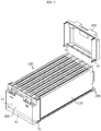
- FIG. 1 is a perspective view schematically illustrating a configuration of a battery module according to an embodiment of the present disclosure
- FIG. 2 is an exploded perspective view illustrating the configuration shown in FIG. 1
- FIG. 3 is a cross-sectional view taken along line A1-A1' of FIG. 1 . That is, FIG. 3 is a vertical cross-sectional view illustrating the battery module according to the embodiment of the present disclosure.
- the battery module of the present disclosure includes a cell assembly 100, a cooling plate 200, a front cover 300, a rear cover 400, a left side cover 500, a right side cover 600, and an upper plate 700.
- the cell assembly 100 includes secondary cells 110.
- the secondary cells 110 are pouch-type secondary cells.
- Each of the pouch-type secondary cells 110 may include an electrode assembly, an electrolyte, and a pouch-type case.
- the electrode assembly is an assembly of electrodes and a separator.
- the electrode assembly may be formed by arranging at least one positive electrode plate and at least one negative electrode plate with a separator therebetween.
- the electrode plates of the electrode assembly may be provided with electrode tabs, respectively, and at least one of the electrode tabs may be connected to an electrode lead.
- the electrode lead may be placed between portions of the pouch-type case, and an end of the electrode lead may be exposed to the outside. The exposed portion of the electrode lead may function as an electrode terminal of the secondary cell 110.
- the pouch-type case may accommodate the electrode assembly together with the electrolyte in an inner space thereof.
- edge portions of the pouch-type case may be sealed by a method such as a thermal fusion method.
- the pouch-type case may include a left pouch and a right pouch.
- Each of the pouches may include an external insulative layer, a metal layer, and an internal adhesive layer, and the internal adhesive layers of the pouches may be fused to each other.
- the battery module of the present disclosure may include various secondary cells known at the time of filing the present disclosure.
- the secondary cells 110 included in the battery module may be stacked in at least one direction.
- a plurality of pouch-type secondary cells 110 may be placed in a standing position in a direction perpendicular to the ground such that two large surfaces of each pouch-type secondary cell 110 may be placed at left and right sides, and sealing portions of each pouch-type secondary cell 110 may be placed at upper, lower, front, and rear sides.
- the secondary cells 110 placed in a standing position as described above may be arranged in parallel to each other in a left-to-right direction such that large surfaces thereof may face each other.
- the cooling plate 200 may be placed below the cell assembly 100. Therefore, the cooling plate 200 may protect the cell assembly 100 from physical or chemical factors such as vibration or moisture applied to the cell assembly 100 from the lower outside of the battery module.
- the cooling plate 200 may include a thermally conductive material. Therefore, when heat is generated from the cell assembly 100, the heat may be transferred to the outside of the battery module through the cooling plate 200.
- the cooling plate 200 may include a metallic material.
- the cell assembly 100 may be horizontally placed on an upper portion of the cooling plate 200.
- each of the secondary cells 110 may stand on the upper portion of the cooling plate 200 such that lower portions of all the secondary cells 110 may adjoin the cooling plate 200. Therefore, heat may be directly transferred from each of secondary cells 110 to the cooling plate 200.
- the cooling plate 200 may have a plate-like shape.
- the cell assembly 100 may be placed on the upper portion of the cooling plate 200. That is, as shown in FIG. 3 , the cell assembly 100 may be in direct contact with the upper portion of the cooling plate 200. In this case, the cooling plate 200 may support the cell assembly 100 in an upward direction.
- the cell assembly 100 does not need cartridges.
- cartridges having a tetragonal ring shape may surround edges of pouch-type secondary cells.
- the pouch-type secondary cells may be accommodated in inner spaces of the cartridges and may be stacked such that the pouch-type secondary cells may be arranged side by side.
- the pouch-type secondary cells 110 may be directly placed on the upper portion of the cooling plate 200 in the battery module. Therefore, the battery module does not need cartridges.
- the battery module since cartridges are not used, the battery module may be easily manufactured, and the volume, weight, and manufacturing costs of the battery module may be reduced.
- heat generated from each of the pouch-type secondary cells 110 is directly conducted to the cooling plate 200, cooling performance may be improved.
- plate-shaped cooling members such as cooling fins may not be provided between the secondary cells 110 and between the cooling plate 200 and the secondary cells 110.
- the volume, weight, and manufacturing costs of the battery module may be further reduced, and the assemblability of the battery module may be further improved.
- the cooling plate 200 may have a concave-convex structure on an upper surface thereof. That is, concave and convex portions may be formed on the upper portion of the cooling plate 200 as shown in FIGS. 2 and 3 .
- each of the pouch-type secondary cells 110 may be easily placed in a standing position and stably maintained in the standing position.
- the secondary cells 110 and the cooling plate 200 may be more closely placed in contact with each other, and owing to an increased contact area, heat exchange efficiency may be increased between the secondary cells 110 and the cooling plate 200.
- the concave and convex portions of the cooling plate 200 may correspond to a lower-side shape of the secondary cells 110.
- concave portions of the cooling plate 200 may have inclined surfaces corresponding to a folded shape of the sealing portions of the secondary cells 110.
- the convex portions of the cooling plate 200 may have inclined surfaces that are not parallel to the ground at top portions thereof and have a slope corresponding to accommodation parts of the secondary cells 110.
- FIG. 4 is a perspective view schematically illustrating a state in which the cell assembly 100 and the cooling plate 200 are separated from the battery module according to an embodiment of the present disclosure.
- a thermal interface material may be placed between the cooling plate 200 and the cell assembly 100.
- the concave and convex portions may be formed on an upper surface of the cooling plate 200, and the thermal interface material may be provided on upper surfaces of the concave and convex portions as indicated by "I" in FIG. 4 .
- the cell assembly 100 may be placed on top of the cooling plate 200, and thus the thermal interface material may be placed between the cooling plate 200 and the cell assembly 100.
- heat transfer between the secondary cells 110 and the cooling plate 200 may be increased owing to the thermal interface material.
- an air layer between the secondary cells 110 and the cooling plate 200 may be removed or reduced owing to the thermal interface material, and thus a larger amount of heat may be more rapidly transferred from the secondary cells 110 to the cooling plate 200.
- the thermal interface material may be prepared in the form of gel and applied to the upper surface of the cooling plate 200 before the cell assembly 100 is placed on the cooling plate 200. In this case, an air layer between the secondary cells 110 and the cooling plate 200 may be more reliably removed.
- the thermal interface material may include a thermal bond.
- heat transfer efficiency may be increased, and the coupling between the cooling plate 200 and the cell assembly 100 may be enhanced.
- the secondary cells 110 may be stably maintained in the standing position owing to the thermal bond, and thus the assemblability of the battery module may be further improved.
- the front cover 300 may be placed in front of the cell assembly 100 to cover a front end portion of the cell assembly 100.
- electrode leads of the secondary cells 110 may protrude from a front side of the cell assembly 100, and thus the front cover 300 may be concave toward the front side of the cell assembly 100 to accommodate the electrode leads.
- the front cover 300 may have a plate-like shape, and both left and right ends of the front cover 300 may be bent at approximately right angles.
- the front cover 300 may protect the front side of the cell assembly 100 from external physical or chemical factors. Furthermore, the front cover 300 may include a metallic material such as steel having high rigidity. Steel is inexpensive and high mechanical strength.
- a lower portion of the front cover 300 may be welded to the cooling plate 200. This will be described in more detail with reference to FIG. 5 .
- FIG. 5 is a view schematically illustrating a welded state of the front cover 300 of the battery module, according to an embodiment of the present disclosure.
- the front cover 300 may be placed on the front side of the cell assembly 100, and a lower end of the front cover 300 may be welded to the cooling plate 200.
- the front cover 300 may include bent portions at both left and right ends thereof, and welding may be performed not only on a center portion but also on both the bent portions of the front cover 300. That is, the lower end of the front cover 300 may be entirely welded to the cooling plate 200 from the left end to the right end thereof as indicated by W3 in FIG. 5 .
- a weld line between the front cover 300 and the cooling plate 200 may have an approximate C-shape extending from the left end to the right end of the front cover 300.
- the front cover 300 may be securely coupled to the cooling plate 200, and sealing between the front cover 300 and the cooling plate 200 may be securely guaranteed.
- the battery module may not need fastening members for coupling the front cover 300 to the cooling plate 200 or sealing members for sealing the interface between the front cover 300 and the cooling plate 200.
- the rear cover 400 may be placed on a rear side of the cell assembly 100 to cover a rear end portion of the cell assembly 100.
- electrode leads of the secondary cells 110 may protrude from the rear side of the cell assembly 100.
- the secondary cells 110 may include electrode leads having different polarities on both the front and rear sides thereof.
- the inner side of the rear cover 400 may be concave toward the rear side of the rear cover 400 to accommodate the electrode leads.
- the rear cover 400 may have a plate-like shape, and both left and right ends of the rear cover 400 may be bent at about right angles.
- the rear cover 400 may protect the rear side of the cell assembly 100 from external physical or chemical factors.
- the rear cover 400 may include a metallic material such as steel having high rigidity.
- a lower portion of the rear cover 400 may be welded to the cooling plate 200.
- the rear cover 400 may be placed on a rear end portion of the cooling plate 200 in a state in which the cell assembly 100 is placed on the cooling plate 200.
- the rear cover 400 may have bent portions at both left and right ends thereof, and welding may be performed on both a central portion and the bent portions of the rear cover 400. That is, a lower end of the rear cover 400 may be entirely welded to the cooling plate 200 from the left end to the right end thereof as indicated by W4 in FIG. 5 .
- a weld line between the rear cover 400 and the cooling plate 200 may have an approximate C-shape extending from the left end to the right end of the rear cover 400.
- the rear cover 400 may be securely coupled to the cooling plate 200, and sealing between the rear cover 400 and the cooling plate 200 may be securely guaranteed.
- the battery module may not need fastening members for coupling the rear cover 400 to the cooling plate 200 or sealing members for sealing the interface between the rear cover 400 and the cooling plate 200.
- the left side cover 500 may be placed on a left side of the cell assembly 100 to cover the left side of the cell assembly 100.
- a flat surface of an outermost secondary cell 110 of the cell assembly 100 may be located on the left side of the cell assembly 100, and thus the left side cover 500 may have a plate-like shape.
- the left side cover 500 may have an approximately rectangular shape as shown in FIG. 2 .
- the left side cover 500 may be welded to the cooling plate 200, the front cover 300, and the rear cover 400. This will be described in more detail with reference to FIG. 6 .
- FIG. 6 is a view schematically illustrating a coupling structure of the side covers 500 and 600 in the battery module according to an embodiment of the present disclosure.
- the left side cover 500 may be placed toward the left side of the cell assembly 100 as indicated by an arrow. Thereafter, a lower end portion of the left side cover 500 may be placed on the upper portion of the cooling plate 200, and front and rear end portions of the left side cover 500 may be respectively brought into contact with the front cover 300 and the rear cover 400. Then, the left side cover 500 may be welded to the cooling plate 200, the front cover 300, and the rear cover 400 along contact portions therebetween. That is, as indicated by W5 in FIG.
- the lower end portion of the left side cover 500 may be welded to a left side portion of the cooling plate 200, the front end portion of the left side cover 500 may be welded to a left side portion of the front cover 300, and the rear end portion of the left side cover 500 may be welded to a left side portion of the rear cover 400.
- the left side cover 500 may be stably fixedly coupled to the cooling plate 200, the front cover 300, and the rear cover 400, and sealing may be guaranteed therebetween. Therefore, the battery module may not need fastening members for fixing the left side cover 500 or fixing a lateral side of the battery module, and sealing members for sealing edge portions of the left side cover 500.
- the right side cover 600 may be placed on a right side of the cell assembly 100 to cover the right side of the cell assembly 100.
- a flat surface of a secondary cell 110 may be located on the right side of the cell assembly 100, and thus the right side cover 600 may also have a plate-like shape.
- the right side cover 600 may have an approximately rectangular plate shape.
- the right side cover 600 may be welded to the cooling plate 200, the front cover 300, and the rear cover 400. That is, a lower end portion of the right side cover 600 may be placed on the upper portion of the cooling plate 200, and front and rear end portions of the right side cover 600 may be respectively brought into contact with the front cover 300 and the rear cover 400. Then, as indicated by W6 in FIG. 6 , the right side cover 600 may be welded along the contact portions.
- the lower end portion of the right side cover 600 may be welded to a right side portion of the cooling plate 200, the front end portion of the right side cover 600 may be welded to a right side portion of the front cover 300, and the rear end portion of the right side cover 600 may be welded to a right side portion of the rear cover 400.
- the right side cover 600 may be stably coupled to the cooling plate 200, the front cover 300, and the rear cover 400 with stably sealing therebetween, and separate fastening members or sealing members may not be used.
- the side covers 500 and 600 may protect lateral sides of the cell assembly 100 from external physical or chemical factors. That is, the left side cover 500 may protect the left side of the cell assembly 100, and the right side cover 600 may protect the right side of the cell assembly 100.
- the left side cover 500 and the right side cover 600 may include a metallic material such as steel having rigidity.
- the upper plate 700 may be placed on an upper portion of the cell assembly 100 to cover the upper portion of the cell assembly 100.
- the upper plate 700 may have a plate-like shape.
- the upper plate 700 may have an approximately rectangular shape.
- the upper plate 700 may protect the upper portion of the cell assembly 100 from external physical or chemical factors.
- the upper plate 700 may include a metallic material such as steel having high rigidity.
- the upper plate 700 may be welded to the left side cover 500 and the right side cover 600. This will be described in more detail with reference to FIG. 7 .
- FIG. 7 is a view schematically illustrating a coupling structure of the upper plate 700 in the battery module according to an embodiment of the present disclosure.
- the upper plate 700 may be moved downward toward the cell assembly 100 and placed on the upper portion of the cell assembly 100.
- left and right sides of the upper plate 700 may be respectively brought into contact with and welded to the left side cover 500 and the right side cover 600. That is, as indicated by W7 in FIG. 7 , a left end portion of the upper plate 700 may be welded to the left side cover 500, and a right end portion of the upper plate 700 may be welded to the right side cover 600.
- the upper plate 700 may be stably fixed to the battery module, and an upper portion of the battery module may be securely sealed.
- the upper plate 700 is welded to only the left side cover 500 and the right side cover 600.
- the upper plate 700 may be welded to the front cover 300 and/or the rear cover 400.
- the upper plate 700 may have a concave-convex structure on a lower surface thereof. That is, like the concave and convex portions formed on the upper portion of the cooling plate 200, concave and convex portions may be formed on a lower portion of the upper plate 700 as shown in FIG. 3 . In this case, the standing position of the pouch-type secondary cells 110 provided in the cell assembly 100 may be more stably maintained, and even when the battery module is impacted or moved, relative movement of the secondary cells 110 may be limited, thereby effectively preventing the secondary cells 110 and connection parts between the secondary cells 110 from being damaged.
- the concave and convex portions of the upper plate 700 may correspond to an upper-side shape of the secondary cells 110. For example, as shown in FIG.
- the concave portions of the upper plate 700 may have inclined surfaces corresponding to the folded shape of the sealing portions of the secondary cells 110.
- the convex portions of the upper plate 700 may have inclined surfaces having a slope corresponding to the accommodation parts of the secondary cells 110.
- each of the cooling plate 200, the front cover 300, the rear cover 400, the left side cover 500, the right side cover 600, and the upper plate 700 are welded to each other by a friction stir welding method.
- weld zones of all the listed parts of the battery module are formed by the friction stir welding method.
- friction stir welding is performed on coupling portions between the front cover 300 and the cooling plate 200 and coupling portions between the rear cover 400 and the cooling plate 200.
- friction stir welding is performed between the left side cover 500 and the cooling plate 200, between the left side cover 500 and the front cover 300, and between the left side cover 500 and the rear cover 400.
- friction stir welding is performed between the right side cover 600 and the cooling plate 200, between the right side cover 600 and the front cover 300, and between the right side cover 600 and the rear cover 400.
- friction stir welding is performed between the upper plate 700 and the left side cover 500 and between the upper plate 700 and the right side cover 600.
- inner components of the battery module may not be damaged or broken by heat or deformation during a welding process. That is, if the amount of heat applied to the pouch-type secondary cells 110 of the cell assembly 100 is equal to or greater than a certain value, parts such as the pouch-type cases, electrode plates, or separators of the pouch-type secondary cells 110 may be damaged. However, since the friction stir welding method uses a relatively small amount of heat compared to other welding methods, the secondary cells 110 may not be damaged.
- the friction stir welding method results in less residual stress and thermal deformation, and thus mechanical characteristics of weld zones may be improved.
- the friction stir welding method guarantees about 90% of the original strength of base metals. Therefore, according to this aspect of the present disclosure, the coupling strength between the cooling plate 200, the front cover 300, the rear cover 400, the left side cover 500, the right side cover 600, and the upper plate 700, which form a case of the battery module, may be stably guaranteed.
- the battery module may be more efficiently sealed. That is, in a friction stir welding process, two base metals may be mixed and welded together, thereby guaranteeing high hermeticity and high sealing performance. Therefore, in this case, sealing performance may be stably guaranteed even though sealing parts such as O-rings or rubber pads are not placed between the components forming the case of the battery module.
- the cooling plate 200 may include an aluminum-containing material having high thermal conductivity
- the left side cover 500, the right side cover 600, the front cover 300, and the rear cover 400 may include a steel-containing material to increase the rigidity of the battery module.
- a dissimilar welding process may be performed between the cooling plate 200 and other components, and the friction stir welding method may guarantee high weldability even in the dissimilar welding process.
- a fusion welding method such as laser welding method is applied to aluminum-steel welding
- compounds such as inter metallic compound (IMC) may be formed, and thus welding strength may be decreased.
- the friction stir welding method is used, since two base metals are bonded together using friction without melting the two base metals, the welding strength between the cooling plate 200 and other components may not be substantially decreased but may be stably maintained.
- this configuration of the present disclosure allows for a butt welding method in which two plates are welded together without having to overlapping the two plates.
- sections of a side cover and the cooling plate 200 or the upper plate 700 may be welded to each other using the friction stir welding method by bringing edges thereof in contact with each other instead of overlapping end portions thereof.
- a side cover and the front cover 300 or the rear cover 400 may also be welded to each other in a state in which edges thereof are in contact with each other instead of end portions thereof overlapping each other.
- the friction stir welding method may also be suitable.
- the volume of the battery module may be reduced, and the energy density of the battery module may be increased.
- the left side cover 500 and/or the right side cover 600 may be welded to at least one of the front cover 300, the rear cover 400, the cooling plate 200, and the upper plate 700 by continuously bringing edges thereof into contact with each other and welding the edges together.
- a front edge of the left side cover 500 may be brought into contact with a left edge of the front cover 300, and the contact edges may be welded to each other.
- the front edge of the left side cover 500 and the left edge of the front cover 300 may be continuously in contact with each other in a form extending from an upper end to a lower end thereof. That is, among weld zones of the left side cover 500 indicated by W5, a front end weld zone of the left side cover 500 may be welded to the front cover 300, and the front end weld zone of the left side cover 500 may have a shape continuously extending from an upper end to a lower end of the left side cover 500.
- a lower edge of the left side cover 500 may be continuously brought into contact with a left edge of the cooling plate 200 and welded thereto.
- a lower end weld zone of the left side cover 500 may be continuously formed in a shape extending from a front end to a rear end of the left side cover 500.
- a rear edge of the left side cover 500 may be continuously brought into contact with a left edge of the rear cover 400 and welded thereto.
- a rear end weld zone of the left side cover 500 may be continuously formed in a shape extending from the upper end to the lower end of the left side cover 500.
- an upper edge of the left side cover 500 may be continuously brought into contact with a left edge of the upper plate 700 and welded thereto.
- an upper end weld zone of the left side cover 500 may be continuously formed in a shape extending from the front end to the rear end of the left side cover 500.
- the right side cover 600 may be welded to at least one of the front cover 300, the rear cover 400, the cooling plate 200, and the upper plate 700 by continuously bringing edges thereof into contact with each other and welding the edges together.
- a front edge, a lower edge and/or a rear edge of the right side cover 600 may be continuously brought into contact with right edges of the front cover 300, the cooling plate 200, and/or the rear cover 400, and may be welded thereto.
- a front end weld zone, a lower end weld zone, and/or a rear end weld zone of the right side cover 600 may be continuously formed in a shape extending from an upper end to a lower end of the right side cover 600 or from a front end to a rear end of the right side cover 600.
- the hermeticity of the battery module may be improved, and the coupling strength between the components of the case of the battery module may be increased. Furthermore, in this case, continuity may be guaranteed in a welding process, and the welding process may be easily performed.
- weld zones of the left side cover 500 and/or the right side cover 600 with at least one of the front cover 300, the rear cover 400, the cooling plate 200, and the upper plate 700 may be formed in a continuous straight line shape from one end to the other end.
- the front end weld zone of the left side cover 500 formed between the left side cover 500 and the front cover 300 may have a straight line shape continuously extending from the upper end to the lower end of the left side cover 500.
- the lower end weld zone of the left side cover 500 formed between the left side cover 500 and the cooling plate 200 may have a straight line shape continuously extending from the front end to the rear end of the left side cover 500.
- the rear end weld zone of the left side cover 500 formed between the left side cover 500 and the rear cover 400 may have a straight line shape continuously extending from the upper end to the lower end of the left side cover 500.
- the upper end weld zone of the left side cover 500 formed between the left side cover 500 and the upper plate 700 may have a straight line shape continuously extending from the front end to the rear end of the left side cover 500.
- the front end weld zone, the lower end weld zone, the upper end weld zone, and/or the rear end weld zone of the right side cover 600 may have a straight line shape continuously extending from the upper end to the lower end of the right side cover 600 or from the front end to the rear end of the right side cover 600.
- each weld zone for welding two components of the case of the battery module to each other may be formed in a straight line shape, and thus a welding process may be smoothly performed.
- a probe of a welding unit may be inserted and moved between bonding surfaces between the components.
- the probe may move linearly, and thus the welding process may be effectively performed.
- each of the weld zones of the left side cover 500 and the right side cover 600 formed with at least one of the front cover 300, the rear cover 400, the cooling plate 200, and the upper plate 700 may be discontinuous from one end to the other end thereof.
- the front end weld zone, the lower end weld zone, and/or the rear end weld zone of the left side cover 500, and/or the front end weld zone, the lower end weld zone, and/or the rear end weld zone of the right side cover 600 that are formed with the front cover 300, the cooling plate 200, and the rear cover 400 may have a discontinuous shape formed by a plurality of weld points.
- weld zones may have small sizes, and thus the process time of welding may be reduced.
- front end weld lines, rear end weld lines, upper end weld lines, and lower end weld lines of the left side cover 500 and the right side cover 600 may be formed in a ring shape. This will be described in more detail with reference to FIG. 8 .
- FIG. 8 is a view schematically illustrating weld zones of the battery module according to an embodiment of the present disclosure.
- visible weld zones are indicated with one-dot chain lines, and invisible weld zones are indicated with broken lines (hidden lines).
- a front end line of the right side cover 600 may be entirely welded to the front cover 300, and a rear end line of the right side cover 600 may be entirely welded to the rear cover 400.
- an upper end line of the right side cover 600 may be entirely welded to the upper plate 700, and a lower end line of the right side cover 600 may be entirely welded to the cooling plate 200.
- the four weld lines may be connected at both ends thereof, and thus a ring shape may be formed. That is, the weld lines of the right side cover 600 may be formed in a substantially tetragonal ring shape along edges of the right side cover 600 as indicated by C1 in FIG. 8 .
- weld lines of the left side cover 500 may be formed in a substantially tetragonal ring shape along edges of the left side cover 500. That is, upper and lower end lines of the left side cover 500 may be entirely welded to the upper plate 700 and the cooling plate 200, and front and rear end lines of the left side cover 500 may be entirely welded to the front cover 300 and the rear cover 400.
- a lower end line of the front cover 300 may be entirely welded to the cooling plate 200.
- a lower end line of the rear cover 400 may also be entirely welded to the cooling plate 200.
- an end of a lower end line of the left side cover 500 may be connected to a line C2
- the other end of the lower end line of the left side cover 500 may be connected to a line C3.
- the lower end line of the right side cover 600 may also be connected to the line C2 and the line C3.
- a lower side of the battery module may be entirely welded along edges of the cooling plate 200. For example, if the cooling plate 200 has an approximately tetragonal plate shape, weld zones of the cooling plate 200 welded to other components may form an approximately tetragonal ring shape.
- bonding and sealing properties of a lower portion of the battery module may be improved.
- the lower portion of the battery module may be exposed to the outside.
- permeation of moisture or foreign substances through the lower side of the battery module may be effectively prevented.
- welding between the cooling plate 200 and the front cover 300 and between the cooling plate 200 and the rear cover 400 may be performed from the lower side of the battery module.
- the present disclosure is not limited to this embodiment.
- all the cooling plate 200, the front cover 300, the rear cover 400, the left side cover 500, the right side cover 600, and the upper plate 700 may include metallic materials.
- the cooling plate 200 may include a material having relatively high thermal conductivity compared to the other components.
- the other components that is, the front cover 300, the rear cover 400, the left side cover 500, the right side cover 600, and the upper plate 700 may include a material having high rigidity.
- the cooling plate 200 may include an aluminum-containing material
- the front cover 300, the rear cover 400, the left side cover 500, the right side cover 600, and the upper plate 700 may include a steel-containing material.
- the rigidity of the battery module may be equal to or higher than a certain degree, and the cooling efficiency of the battery module may also be high.
- the battery module of the present disclosure may be mounted on a lower portion of a vehicle with the upper plate 700 facing the inside of the vehicle and the cooling plate 200 facing the outside of the vehicle.
- the cooling plate 200 includes a material having higher thermal conductivity than the other components of the case, heat may be effectively dissipated through the cooling plate 200.
- a cooling fluid such as air or water flows along the lower portion of the battery module, heat may be discharged from the inside of the battery module to the cooling fluid through the cooling plate 200 located on the lower portion of the battery module.
- an insulative coating layer including an electrically insulative material may be formed on at least a portion of an inner surface of at least one of the front cover 300, the rear cover 400, the left side cover 500, the right side cover 600, and the upper plate 700.
- an insulative sheet including an electrically insulative material may be provided on at least a portion of the inner surface of at least one of the front cover 300, the rear cover 400, the left side cover 500, the right side cover 600, and the upper plate 700.
- the cell assembly 100 may be stably insulated.
- the front cover 300, the rear cover 400, the left side cover 500, the right side cover 600, and the upper plate 700 are welded by the above-described friction stir welding method.
- the friction stir welding method a large amount of heat is not generated, and thus the insulative coating layer or the insulative sheet may not be broken. Therefore, in this case, the insulation of the battery module may be stably maintained.
- At least one of the front cover 300 and the rear cover 400 may include a stepped portion. This will be described in more detail with reference to FIG. 9 .
- FIG. 9 is a partial cross-sectional view taken along line A2-A2' of FIG. 1 . That is, FIG. 9 illustrates a portion of a horizontal cross-section of the battery module viewed from above, particularly, a left corner portion of the front cover 300 on an enlarged scale, according to an embodiment of the present disclosure.
- a stepped portion having an inwardly recessed shape may be formed on a left end portion, particularly, a left bent portion of the front cover 300 as indicated by D1.
- the front end portion of the left side cover 500 may be placed on a recessed portion formed by the stepped portion. That is, the front end portion of the left side cover 500 having a plate shape may be placed on the recessed portion by inwardly inserting the front end portion of the left side cover 500 from the outside of the battery module.
- the step portion of the front cover 300 may have a size equal to or similar to the thickness of the left side cover 500.
- an outer surface of the front cover 300 and an outer surface of the left side cover 500 may form a single flat surface.
- a stepped portion having an inwardly recessed shape may be formed on a right end portion of the front cover 300, and the front end portion of the right side cover 600 may be inserted into the stepped portion in an outside-to-inside direction.
- the side covers 500 and 600 may be easily assembled to the front cover 300.
- assembling positions of the side covers 500 and 600 may be guided by the stepped portions of the front cover 300, and thus the front cover 300 and the side covers 500 and 600 may be more easily assembled.
- the rigidity of the battery module may be enhanced. That is, since the front cover 300 is placed on inner sides of the front end portions of the side covers 500 and 600, although force is applied to the side covers 500 and 600 from the outside, the front cover 300 may support the side covers 500 and 600 in an outward direction.
- friction stir welding may be more easily performed.
- a probe of a welding unit may be brought into contact with and inserted between bonding surfaces of the front cover 300 and the left side cover 500 while the probe is rotated, and during this process, force may be applied to the vicinity of the bonding surfaces of the front cover 300 and the left side cover 500 in an inward direction as indicated by the arrow T1.
- a portion D1 formed by the stepped portion of the front cover 300 may support pressure applied in the direction indicated by the arrow T1. Therefore, the configuration of the present disclosure in which stepped portions are formed may be more preferably applied to the case in which a friction stir welding process is performed between the front cover 300 and the left side cover 500.
- FIG. 9 illustrates only the front cover 300
- stepped portions may also be formed on the rear cover 400 in a similar manner such that the rear end portion of the left side cover 500 and the rear end portion of the right side cover 600 may be placed on the stepped portions of the rear cover 400 by outside-to-inside insertion motions.
- a stepped portion may be formed on a left end portion of the rear cover 400 in a shape symmetrical to the stepped portion of the front cover 300 shown in FIG. 9 in a front-to-rear direction (in FIG. 9 , in a left-to-right direction).
- a stepped portion may be formed on a right end portion of the rear cover 400 such that the rear end portion of the right side cover 600 may be inserted into and placed on the stepped portion.
- At least one of the cooling plate 200 and the upper plate 700 may include a stepped portion. This will be described in more detail with reference to FIGS. 10 and 11 .
- FIGS. 10 and 11 are enlarged views illustrating portions B1 and B2 of FIG. 3 , respectively.
- a stepped portion having an inwardly recessed shape may be formed on a right end portion of the cooling plate 200 as indicated by D2.
- the lower end portion of the right side cover 600 may be placed on a recessed portion formed by the stepped portion by inwardly inserting the lower end portion of the right side cover 600 from the outside.
- the stepped portion formed on the cooling plate 200 may have a size corresponding to the thickness of the right side cover 600.
- a stepped portion having an inwardly recessed shape may be formed on a left end portion of the cooling plate 200 so as to receive the lower end portion of the left side cover 500.
- the cooling plate 200 and the side covers 500 and 600 may be easily assembled. That is, since assembling positions of the side covers 500 and 600 are guided by the stepped portions of the cooling plate 200, the cooling plate 200 and the side covers 500 and 600 may be more easily assembled.
- the rigidity of the battery module may be enhanced. That is, since the cooling plate 200 is placed between the lower end portions of the side covers 500 and 600, although horizontal force is applied from the outside of the side covers 500 and 600, the cooling plate 200 may support the side covers 500 and 600 in outward directions. In addition, the stepped portions of the cooling plate 200 may also support the side covers 500 and 600 in an upward direction.
- a friction stir welding process may be more easily performed.
- a probe of a welding unit may be brought into contact with and inserted between bonding surfaces of the cooling plate 200 and the right side cover 600, and during this process, force may be applied in an inward direction as indicated by the arrow T2.
- a portion D2 formed by the stepped portion of the cooling plate 200 may support pressure applied in the direction indicated by the arrow T2.
- a stepped portion having an inwardly recessed shape may be formed on the right end portion of the upper plate 700.
- an upper end portion of the right side cover 600 may be brought into contact with the stepped portion of the upper plate 700 by inwardly inserting the upper end portion of the right side cover 600 from the outside.
- a stepped portion having an inwardly recessed shape may be formed on the left end portion of the upper plate 700, and an upper end portion of the left side cover 500 may be inserted into the stepped portion of the upper plate 700.
- This configuration of the present disclosure may be advantageous like the configuration in which stepped portions are formed on the cooling plate 200. That is, according to this configuration, the upper plate 700 and the side covers 500 and 600 may be easily assembled, and the rigidity of the battery module may be enhanced. In addition, according to this configuration, a friction stir welding process may be easily performed between the upper plate 700 and the side covers 500 and 600.
- all joining portions (bonding surfaces) of the left side cover 500 and/or the right side cover 600 to be jointed to (bonded to) the front cover 300, the rear cover 400, the cooling plate 200, and the upper plate 700 may be exposed at lateral sides of the battery module.
- bonding surfaces of the left side cover 500 and the front cover 300 may be approximately perpendicular to the outer surfaces of the left side cover 500 and the front cover 300.
- open sides (indicated by T1) of the bonding surfaces of the left side cover 500 and the front cover 300 may face a right side of the battery module (on an upper side in FIG. 9 ).
- bonding surfaces of the right side cover 600 and the cooling plate 200 may be approximately perpendicular to an outer surface of the right side cover 600, that is, the outer surface of the battery module.
- open sides (indicated by T2) of the bonding surfaces of the right side cover 600 and the cooling plate 200 may face a right side of the battery module (on a right side in FIG. 9 ).
- bonding surfaces of the right side cover 600 and the upper plate 700 may be approximately perpendicular to the outer surface of the right side cover 600.
- open sides (indicated by T3) of the bonding surfaces of the right side cover 600 and the upper plate 700 may face the right side of the battery module.
- all open sides of joining portions (bonding surfaces) of the left side cover 500 and the right side cover 600 to be jointed to (bonded to) other components are exposed at lateral sides of the battery module, and thus a welding process, particularly, a friction stir welding process may be smoothly performed .
- a welding process particularly, a friction stir welding process may be smoothly performed .
- the probe may be inserted into the open sides of the joint portions as indicated by arrows T1 to T3 in FIGS. 9 to 11 .
- the probe of the welding unit may be moved away from the battery module in a horizontal direction. Therefore, there is no structure that interferes with the process of inserting and moving the probe of the welding unit between the bonding surfaces, and thus the welding process may be efficiently performed.
- Electrode leads may be located on the front end or rear end of the battery module, and according to this configuration, such electrode leads may not be damages or may not interfere with other structures or parts.
- each of the side covers 500 and 600 may have a tetragonal plate shape having four sides, and all four corners of the tetragonal plate shape at which two sides meet each other may be rounded.
- corners of the side covers 500 and 600 may be curved with a radius equal to or greater than 10 mm.
- a friction stir welding process may be performed with improved processability. That is, if corners are rounded with a radius equal to or greater than a certain value, edges of the side covers 500 and 600 may be continuously welded, and thus weld lines may be formed in a ring shape.
- the case (module case) of the battery module may include the cooling plate 200, the front cover 300, the rear cover 400, the left side cover 500, the right side cover 600, and the upper plate 700.
- the components of the module case may be coupled to each other by welding as described above. In this case, the sequence of welding may be variously implemented.
- the front cover 300 and the rear cover 400 may be brought into contact with the cooling plate 200 respectively from the front end portion and the rear end portion of the cell assembly 100 as shown in FIG. 5 and may then be welded to the cooling plate 200.
- the left side cover 500 and the right side cover 600 may be placed on the lateral sides of the cell assembly 100 and may then be welded to the cooling plate 200, the front cover 300, and the rear cover 400.
- the upper plate 700 may be placed on the upper portion of the cell assembly 100 and may then be welded to the left side cover 500 and the right side cover 600.
- FIG. 12 is an exploded perspective view schematically illustrating a welding configuration of the battery module according to another embodiment of the present disclosure.
- the cell assembly 100 may be placed on the upper portion of the cooling plate 200 as indicated by an arrow S1.
- an assembly of the upper plate 700, the left side cover 500, and the rear cover 400 may be coupled to the cell assembly 100 in a downward direction as indicated by an arrow S2.
- the assembly of the upper plate 700, the left side cover 500, and the rear cover 400 may be previously prepared by welding the upper plate 700, the left side cover 500, and the rear cover 400 to each other.
- the assembly may be prepared by the friction stir welding method.
- the front cover 300 may be placed on the front end portion of the cell assembly 100 as indicated by an arrow S3 and may then be welded to the cooling plate 200 and the left side cover 500.
- the right side cover 600 may be placed on the right side of the cell assembly 100 as indicated by an arrow S4 and may then be welded to the cooling plate 200, the front cover 300, the rear cover 400, and the upper plate 700.
- the battery module may further include a heat shield between the cell assembly 100 and a weld zone of at least one of the cooling plate 200, the front cover 300, the rear cover 400, the left side cover 500, the right side cover 600, and the upper plate 700. This will be described in more detail with reference to FIG. 13 .
- FIG. 13 is a cross-sectional view illustrating a portion of the battery module according to another embodiment of the present disclosure.
- FIG. 13 may illustrate another embodiment of the configuration shown in FIG. 9 .
- inner components of the battery module such as pouch-type cases, electrode leads, or bus bars of the secondary cells may not be deformed or damaged.
- the friction stir welding method generate a small amount of heat compared to other welding methods, the above-described configuration may fundamentally prevent even such a small amount of heat from flowing into the battery module.
- the heat shielding part F may include a material having a heat transfer coefficient lower than that of components of the case of the battery module such as the front cover 300.
- the heat shield F may include a heat insulating material containing a heat-resistant resin such as polyimide, a fiber such as glass wool or rock wool, and/or a ceramic material.
- the heat shield F may be provided on the inner surface of the front cover 300.
- electrode leads may be placed at a side of the front cover 300, and according to the configuration, the heat shield F may reduce or prevent transfer of welding heat to the electrode leads.
- the heat shield F may be provided on an inner surface of a component of the case of the battery module such as the front cover 300, the side covers 500 and 600, or the rear cover 400 by a coating method, or may be provided on an inner surface of a component such as the front cover 300 in the form of a separate sheet. Alternatively, the heat shield F may protrude in a convex shape from an inner surface of a component of the case of the battery module such as the front cover 300, the side covers 500 and 600, or the rear cover 400.
- the heat shield F is provided on the front cover 300.
- the heat shield F may be provided on inner surfaces of other components of the case of the battery module, that is, on inner surfaces of the left side cover 500, the right side cover 600, the rear cover 400, the cooling plate 200, and/or the upper plate 700.
- a battery pack may include the battery module.
- the battery pack of the present disclosure may further include a pack case for accommodating the battery module and devices for controlling charge and discharge operations of the battery module such as a battery management system (BMS), a current sensor, or a fuse.
- BMS battery management system
- a current sensor current sensor
- a fuse fuse
- the battery module of the present disclosure may be applied automobiles such as electric vehicles or hybrid vehicles. That is, according to the present disclosure, an automobile may include the battery module. Particular, automobiles may be exposed to various vibrations and large impact and are thus required to have high rigidity. In addition, since automobiles are usually placed outdoor, it is necessary to seal automobiles so as to prevent permeation of moisture or foreign substances. When the battery module of the present disclosure is applied to such automobiles, the battery module may be configured to have high strength, rigidity, and sealing performance, and improve productivity.
Applications Claiming Priority (2)
| Application Number | Priority Date | Filing Date | Title |
|---|---|---|---|
| KR20150135686 | 2015-09-24 | ||
| PCT/KR2016/010702 WO2017052296A1 (ko) | 2015-09-24 | 2016-09-23 | 배터리 모듈 |
Publications (3)
| Publication Number | Publication Date |
|---|---|
| EP3343691A1 EP3343691A1 (en) | 2018-07-04 |
| EP3343691A4 EP3343691A4 (en) | 2018-08-15 |
| EP3343691B1 true EP3343691B1 (en) | 2020-04-01 |
Family
ID=58386551
Family Applications (1)
| Application Number | Title | Priority Date | Filing Date |
|---|---|---|---|
| EP16849021.7A Active EP3343691B1 (en) | 2015-09-24 | 2016-09-23 | Battery module |
Country Status (6)
| Country | Link |
|---|---|
| US (1) | US10658716B2 (zh) |
| EP (1) | EP3343691B1 (zh) |
| JP (1) | JP6599483B2 (zh) |
| KR (1) | KR102050530B1 (zh) |
| CN (1) | CN107534196B (zh) |
| WO (1) | WO2017052296A1 (zh) |
Families Citing this family (56)
| Publication number | Priority date | Publication date | Assignee | Title |
|---|---|---|---|---|
| KR102258827B1 (ko) * | 2017-06-02 | 2021-05-31 | 주식회사 엘지에너지솔루션 | 배터리 팩과 이를 포함하는 자동차 |
| KR102148993B1 (ko) * | 2017-06-13 | 2020-08-27 | 주식회사 엘지화학 | 배터리 모듈 |
| CN107706325B (zh) * | 2017-06-30 | 2020-12-01 | 多氟多新能源科技有限公司 | 电源模块及车辆 |
| KR102248228B1 (ko) | 2017-09-26 | 2021-05-03 | 주식회사 엘지화학 | 전자기 펄스 접합 기술을 적용한 배터리 모듈 하우징 및 배터리 모듈 하우징 제조 방법 |
| KR102203250B1 (ko) * | 2017-11-29 | 2021-01-13 | 주식회사 엘지화학 | 엔드 프레임을 구비한 배터리 모듈 |
| KR102050139B1 (ko) * | 2017-12-12 | 2019-11-28 | 주식회사 이노윌 | 내압성능이 향상된 주전열면 열교환유닛과 그 제조방법 및 이 주전열면 열교환유닛을 이용한 열교환시스템 |
| KR102527004B1 (ko) * | 2017-12-20 | 2023-04-27 | 에스케이온 주식회사 | 배터리 모듈 |
| JP7031284B2 (ja) * | 2017-12-20 | 2022-03-08 | 株式会社Gsユアサ | 蓄電装置 |
| KR102128588B1 (ko) * | 2017-12-26 | 2020-07-08 | 에스케이이노베이션 주식회사 | 배터리 모듈 및 이의 제조 방법 |
| US20190198952A1 (en) * | 2017-12-26 | 2019-06-27 | Sk Innovation Co., Ltd. | Battery module and manufacturing method thereof |
| KR102270269B1 (ko) | 2018-01-17 | 2021-06-28 | 주식회사 엘지에너지솔루션 | 리유즈, 리사이클 내지 리웍이 용이한 접착 구조를 갖는 배터리 모듈 하우징 및 이를 포함하는 배터리 모듈 |
| KR102388127B1 (ko) | 2018-01-31 | 2022-04-19 | 주식회사 엘지에너지솔루션 | 탑 커버, 이를 구비한 배터리 모듈, 그리고 이를 포함하는 배터리 팩 및 자동차 |
| KR102277035B1 (ko) * | 2018-03-21 | 2021-07-13 | 주식회사 엘지에너지솔루션 | 배터리 모듈, 이러한 배터리 모듈을 포함하는 배터리 팩 및 이러한 배터리 팩을 포함하는 자동차 |
| DE102018205765A1 (de) * | 2018-04-17 | 2019-10-17 | Volkswagen Aktiengesellschaft | Montageanordnung eines elektrisch antreibbaren Kraftfahrzeugs |
| JP7348174B2 (ja) | 2018-06-05 | 2023-09-20 | 三洋電機株式会社 | 電池モジュール及びこれを備える車両 |
| KR102372348B1 (ko) * | 2018-06-08 | 2022-03-07 | 주식회사 엘지에너지솔루션 | 개선된 냉각 구조를 갖는 배터리 모듈 |
| KR20200003600A (ko) | 2018-07-02 | 2020-01-10 | 에스케이이노베이션 주식회사 | 배터리 모듈 |
| CN109103372B (zh) * | 2018-07-16 | 2021-06-11 | 合肥国轩高科动力能源有限公司 | 一种电动汽车用电池模组 |
| KR102424400B1 (ko) * | 2018-09-13 | 2022-07-22 | 주식회사 엘지에너지솔루션 | 열수축성 튜브를 포함하는 배터리 모듈 |
| KR102315847B1 (ko) | 2018-10-05 | 2021-10-21 | 주식회사 엘지에너지솔루션 | 용접 불량을 방지할 수 있는 전지팩 프레임을 포함하는 전지팩 및 이를 제조하기 위한 가압 지그 |
| KR20200055215A (ko) * | 2018-11-12 | 2020-05-21 | 현대자동차주식회사 | 배터리 모듈 |
| KR102317638B1 (ko) | 2018-12-05 | 2021-10-25 | 주식회사 엘지에너지솔루션 | 셀 적층체의 보호 구조를 갖는 배터리 모듈 |
| KR102392767B1 (ko) * | 2018-12-26 | 2022-04-28 | 주식회사 엘지에너지솔루션 | 내측 커버를 포함하는 배터리 모듈 |
| CN209401683U (zh) * | 2018-12-29 | 2019-09-17 | 宁德时代新能源科技股份有限公司 | 二次电池和电池模组 |
| KR102380443B1 (ko) * | 2019-01-04 | 2022-03-29 | 주식회사 엘지에너지솔루션 | 인접 배터리 모듈들로 열을 분산할 수 있는 구조를 갖는 에너지 저장 시스템 |
| KR102640879B1 (ko) * | 2019-02-08 | 2024-02-23 | 에스케이온 주식회사 | 배터리 모듈 및 이의 제조방법 |
| KR102416919B1 (ko) * | 2019-02-26 | 2022-07-04 | 주식회사 엘지에너지솔루션 | 전지 모듈 |
| KR20200109147A (ko) * | 2019-03-12 | 2020-09-22 | 에스케이이노베이션 주식회사 | 파우치형 이차전지 및 이를 포함하는 배터리 모듈 |
| KR20200111525A (ko) * | 2019-03-19 | 2020-09-29 | 주식회사 엘지화학 | 연장된 길이를 갖는 절연 패드를 구비하는 배터리 모듈, 이를 포함하는 배터리 팩 및 자동차 |
| CN113767512B (zh) * | 2019-03-29 | 2023-12-29 | 三洋电机株式会社 | 电源装置和具有该电源装置的电动车辆以及蓄电装置、电源装置的制造方法 |
| WO2020202669A1 (ja) * | 2019-03-29 | 2020-10-08 | 三洋電機株式会社 | 電源装置及びこれを用いた電動車両並びに蓄電装置、電源装置用締結部材、電源装置の製造方法、電源装置用締結部材の製造方法 |
| KR20200125184A (ko) * | 2019-04-26 | 2020-11-04 | 에스케이이노베이션 주식회사 | 배터리 모듈 |
| CN110010999B (zh) * | 2019-05-06 | 2024-03-15 | 西南交通大学 | 一种电池散热装置 |
| KR20200136229A (ko) * | 2019-05-27 | 2020-12-07 | 에스케이이노베이션 주식회사 | 배터리 모듈 |
| CN209747611U (zh) * | 2019-06-28 | 2019-12-06 | 江苏时代新能源科技有限公司 | 电池模组 |
| KR102472690B1 (ko) * | 2019-07-19 | 2022-11-29 | 주식회사 엘지에너지솔루션 | 전지 모듈 및 이를 포함하는 전지팩 |
| WO2021024776A1 (ja) * | 2019-08-03 | 2021-02-11 | 三洋電機株式会社 | 電源装置とこの電源装置を備える電動車両及び蓄電装置 |
| KR102473336B1 (ko) * | 2019-10-07 | 2022-12-01 | 주식회사 엘지에너지솔루션 | 전지 모듈 및 이를 포함하는 전지팩 |
| KR102398574B1 (ko) * | 2019-10-10 | 2022-05-13 | 주식회사 엘지에너지솔루션 | 전지 모듈 및 이를 포함하는 전지 팩 |
| KR102464825B1 (ko) * | 2019-10-10 | 2022-11-07 | 주식회사 엘지에너지솔루션 | 전지 모듈 및 이를 포함하는 전지팩 |
| KR20210064935A (ko) * | 2019-11-26 | 2021-06-03 | 주식회사 엘지에너지솔루션 | 배터리 모듈 |
| KR20210099424A (ko) * | 2020-02-04 | 2021-08-12 | 주식회사 엘지에너지솔루션 | 전지 모듈 및 이를 포함하는 전지팩 |
| KR20210125674A (ko) * | 2020-04-09 | 2021-10-19 | 에스케이이노베이션 주식회사 | 배터리 모듈 제조방법 및 이를 통해 제조된 배터리 모듈 |
| KR20210129489A (ko) * | 2020-04-20 | 2021-10-28 | 에스케이이노베이션 주식회사 | 배터리 모듈 |
| KR20210133528A (ko) * | 2020-04-29 | 2021-11-08 | 주식회사 엘지에너지솔루션 | 전지 모듈 및 이를 포함하는 전지 팩 |
| WO2021232338A1 (zh) * | 2020-05-21 | 2021-11-25 | 宁德时代新能源科技股份有限公司 | 电池模块、电池模块组件及其生产方法以及装置 |
| KR20220021611A (ko) * | 2020-08-14 | 2022-02-22 | 주식회사 엘지에너지솔루션 | 전지 모듈 및 이를 포함하는 전지팩 |
| KR20220025413A (ko) * | 2020-08-24 | 2022-03-03 | 주식회사 엘지에너지솔루션 | 전지 모듈 및 이를 포함하는 전지 팩 |
| KR20220047050A (ko) * | 2020-10-08 | 2022-04-15 | 주식회사 엘지에너지솔루션 | 배터리 모듈, 배터리 랙, 및 전력 저장 장치 |
| CN114846682A (zh) * | 2020-10-19 | 2022-08-02 | 株式会社Lg新能源 | 电池模块及包括该电池模块的电池组 |
| DE102020127794B8 (de) * | 2020-10-22 | 2022-03-17 | Bayerische Motoren Werke Aktiengesellschaft | Gehäuseteil, insbesondere Gehäuseunterteil, eines Energiespeichergehäuses, Energiespeichergehäuse sowie Verfahren zum Herstellen eines Gehäuseteils |
| DE102020213561B3 (de) * | 2020-10-28 | 2022-04-21 | Audi Aktiengesellschaft | Zellmodul sowie Verfahren zur Herstellung eines solchen |
| KR20220081540A (ko) * | 2020-12-09 | 2022-06-16 | 에스케이온 주식회사 | 배터리 모듈의 하부케이스 제조방법 및 배터리 모듈의 하부케이스 |
| KR102357486B1 (ko) * | 2021-04-07 | 2022-02-08 | 광성기업 주식회사 | 배터리 팩 케이스 |
| KR20230134660A (ko) * | 2022-03-14 | 2023-09-22 | 에스케이온 주식회사 | 배터리 모듈 및 이를 포함하는 배터리 팩 |
| CN114792864A (zh) * | 2022-05-31 | 2022-07-26 | 东风汽车集团股份有限公司 | 电池包下箱体结构 |
Citations (2)
| Publication number | Priority date | Publication date | Assignee | Title |
|---|---|---|---|---|
| WO1989000344A2 (en) * | 1987-07-03 | 1989-01-12 | Chloride Silent Power Limited | Batteries |
| WO2012002907A1 (en) * | 2011-01-24 | 2012-01-05 | Guoan Feng | Power battery pack cooling apparatus |
Family Cites Families (20)
| Publication number | Priority date | Publication date | Assignee | Title |
|---|---|---|---|---|
| JP2001135282A (ja) * | 1999-11-04 | 2001-05-18 | Nec Mobile Energy Kk | 密閉型電池 |
| JP2012069408A (ja) * | 2010-09-24 | 2012-04-05 | Hitachi Maxell Energy Ltd | 電気化学素子モジュール |
| KR101481198B1 (ko) * | 2010-11-08 | 2015-01-13 | 주식회사 엘지화학 | 전지모듈 및 이를 포함하는 리튬이차 전지팩 |
| KR20120048802A (ko) | 2010-11-08 | 2012-05-16 | 현 규 곽 | 전지케이스 |
| KR101271858B1 (ko) | 2011-03-08 | 2013-06-07 | 로베르트 보쉬 게엠베하 | 방열 특성이 향상된 배터리 팩 |
| JP5537497B2 (ja) * | 2011-05-26 | 2014-07-02 | 株式会社日立製作所 | 電池モジュール |
| KR101271883B1 (ko) * | 2011-07-22 | 2013-06-05 | 로베르트 보쉬 게엠베하 | 배터리 모듈 |
| US20130171487A1 (en) * | 2011-12-30 | 2013-07-04 | Roger Bull | Rechargeable battery and method |
| KR101447062B1 (ko) | 2012-01-26 | 2014-11-03 | 주식회사 엘지화학 | 전지모듈 및 이를 포함하는 전지팩 |
| US20130243079A1 (en) * | 2012-03-19 | 2013-09-19 | Nokia Siemens Networks Oy | Storage and processing savings when adapting video bit rate to link speed |
| JP2015111493A (ja) * | 2012-03-28 | 2015-06-18 | 三洋電機株式会社 | 電源装置及びこれを備える車両並びに蓄電装置 |
| JP5993615B2 (ja) | 2012-05-22 | 2016-09-14 | 日立オートモティブシステムズ株式会社 | 蓄電モジュール |
| JP5475206B1 (ja) * | 2012-08-31 | 2014-04-16 | 日立ビークルエナジー株式会社 | 角形二次電池 |
| KR20140085890A (ko) * | 2012-12-28 | 2014-07-08 | 현대자동차주식회사 | 고전압 배터리팩용 배터리모듈 조립체 |
| US20140272508A1 (en) * | 2013-03-15 | 2014-09-18 | Vecture Inc. | Battery pack system |
| JP6174381B2 (ja) | 2013-06-06 | 2017-08-02 | 日立オートモティブシステムズ株式会社 | 蓄電ブロックおよび蓄電モジュール |
| KR20140145250A (ko) | 2013-06-12 | 2014-12-23 | 엘지전자 주식회사 | 전기 자동차의 배터리 냉각 시스템 |
| US9525195B2 (en) * | 2013-07-30 | 2016-12-20 | Johnson Controls Technology Corporation | Remanufacturing methods for battery module |
| US9887439B2 (en) * | 2014-05-13 | 2018-02-06 | Ford Global Technologies, Llc | Method of biasing a battery cell to enhance thermal energy transfer |
| CA2953412A1 (en) * | 2014-06-27 | 2015-12-30 | Dana Canada Corporation | Multi-sided heat exchangers with compliant heat transfer surfaces |
-
2016
- 2016-09-23 JP JP2017565912A patent/JP6599483B2/ja active Active
- 2016-09-23 US US15/567,184 patent/US10658716B2/en active Active
- 2016-09-23 KR KR1020160122320A patent/KR102050530B1/ko active IP Right Grant
- 2016-09-23 CN CN201680027427.8A patent/CN107534196B/zh active Active
- 2016-09-23 EP EP16849021.7A patent/EP3343691B1/en active Active
- 2016-09-23 WO PCT/KR2016/010702 patent/WO2017052296A1/ko active Application Filing
Patent Citations (2)
| Publication number | Priority date | Publication date | Assignee | Title |
|---|---|---|---|---|
| WO1989000344A2 (en) * | 1987-07-03 | 1989-01-12 | Chloride Silent Power Limited | Batteries |
| WO2012002907A1 (en) * | 2011-01-24 | 2012-01-05 | Guoan Feng | Power battery pack cooling apparatus |
Also Published As
| Publication number | Publication date |
|---|---|
| EP3343691A4 (en) | 2018-08-15 |
| JP6599483B2 (ja) | 2019-10-30 |
| EP3343691A1 (en) | 2018-07-04 |
| KR102050530B1 (ko) | 2019-12-02 |
| US20180138565A1 (en) | 2018-05-17 |
| JP2018518032A (ja) | 2018-07-05 |
| CN107534196B (zh) | 2020-03-17 |
| KR20170036639A (ko) | 2017-04-03 |
| US10658716B2 (en) | 2020-05-19 |
| WO2017052296A1 (ko) | 2017-03-30 |
| CN107534196A (zh) | 2018-01-02 |
Similar Documents
| Publication | Publication Date | Title |
|---|---|---|
| EP3343691B1 (en) | Battery module | |
| EP3340338B1 (en) | Battery module | |
| KR101821378B1 (ko) | 전극 리드와 버스바 사이의 결합력 및 공정성이 향상된 배터리 모듈 및 이를 포함하는 배터리 팩 | |
| JP7047220B2 (ja) | 二次電池及びバスバーを含むバッテリーモジュール | |
| KR20100067464A (ko) | 전지 모듈 | |
| JP2006040901A (ja) | 二次電池 | |
| US11342632B2 (en) | Battery module | |
| KR102258827B1 (ko) | 배터리 팩과 이를 포함하는 자동차 | |
| KR20150068759A (ko) | 이차전지 | |
| KR101658587B1 (ko) | 리튬 이차전지 및 이를 포함하는 전지팩 | |
| EP3926734A1 (en) | Battery module and battery pack including same | |
| CN113939946A (zh) | 电池模块和包括该电池模块的电池组 | |
| CN112042004A (zh) | 包括模块壳体的电池模块 | |
| KR101627629B1 (ko) | 이차전지 | |
| KR20180103414A (ko) | 연장된 보호 필름을 포함하는 파우치형 전지셀 | |
| CN216872164U (zh) | 电池单元、电池模块和车辆 | |
| KR101996421B1 (ko) | 배터리 모듈 | |
| TW202213855A (zh) | 包括冷卻件之電池模組、包括該電池模組之電池組以及電子元件 | |
| CN115458848A (zh) | 具备固定构件的电池 |
Legal Events
| Date | Code | Title | Description |
|---|---|---|---|
| STAA | Information on the status of an ep patent application or granted ep patent |
Free format text: STATUS: THE INTERNATIONAL PUBLICATION HAS BEEN MADE |
|
| PUAI | Public reference made under article 153(3) epc to a published international application that has entered the european phase |
Free format text: ORIGINAL CODE: 0009012 |
|
| STAA | Information on the status of an ep patent application or granted ep patent |
Free format text: STATUS: REQUEST FOR EXAMINATION WAS MADE |
|
| 17P | Request for examination filed |
Effective date: 20171027 |
|
| AK | Designated contracting states |
Kind code of ref document: A1 Designated state(s): AL AT BE BG CH CY CZ DE DK EE ES FI FR GB GR HR HU IE IS IT LI LT LU LV MC MK MT NL NO PL PT RO RS SE SI SK SM TR |
|
| AX | Request for extension of the european patent |
Extension state: BA ME |
|
| A4 | Supplementary search report drawn up and despatched |
Effective date: 20180716 |
|
| RIC1 | Information provided on ipc code assigned before grant |
Ipc: H01M 2/10 20060101ALI20180706BHEP Ipc: H01M 10/625 20140101ALN20180706BHEP Ipc: H01M 10/6554 20140101AFI20180706BHEP Ipc: H01M 10/613 20140101ALI20180706BHEP |
|
| DAV | Request for validation of the european patent (deleted) | ||
| DAX | Request for extension of the european patent (deleted) | ||
| STAA | Information on the status of an ep patent application or granted ep patent |
Free format text: STATUS: EXAMINATION IS IN PROGRESS |
|
| 17Q | First examination report despatched |
Effective date: 20190322 |
|
| GRAP | Despatch of communication of intention to grant a patent |
Free format text: ORIGINAL CODE: EPIDOSNIGR1 |
|
| STAA | Information on the status of an ep patent application or granted ep patent |
Free format text: STATUS: GRANT OF PATENT IS INTENDED |
|
| RIC1 | Information provided on ipc code assigned before grant |
Ipc: H01M 2/10 20060101ALI20191009BHEP Ipc: H01M 10/613 20140101ALI20191009BHEP Ipc: H01M 10/625 20140101ALN20191009BHEP Ipc: H01M 10/6554 20140101AFI20191009BHEP |
|
| INTG | Intention to grant announced |
Effective date: 20191031 |
|
| GRAS | Grant fee paid |
Free format text: ORIGINAL CODE: EPIDOSNIGR3 |
|
| GRAA | (expected) grant |
Free format text: ORIGINAL CODE: 0009210 |
|
| STAA | Information on the status of an ep patent application or granted ep patent |
Free format text: STATUS: THE PATENT HAS BEEN GRANTED |
|
| AK | Designated contracting states |
Kind code of ref document: B1 Designated state(s): AL AT BE BG CH CY CZ DE DK EE ES FI FR GB GR HR HU IE IS IT LI LT LU LV MC MK MT NL NO PL PT RO RS SE SI SK SM TR |
|
| REG | Reference to a national code |
Ref country code: GB Ref legal event code: FG4D |
|
| REG | Reference to a national code |
Ref country code: CH Ref legal event code: EP Ref country code: AT Ref legal event code: REF Ref document number: 1252564 Country of ref document: AT Kind code of ref document: T Effective date: 20200415 |
|
| REG | Reference to a national code |
Ref country code: DE Ref legal event code: R096 Ref document number: 602016033274 Country of ref document: DE |
|
| REG | Reference to a national code |
Ref country code: IE Ref legal event code: FG4D |
|
| PG25 | Lapsed in a contracting state [announced via postgrant information from national office to epo] |
Ref country code: BG Free format text: LAPSE BECAUSE OF FAILURE TO SUBMIT A TRANSLATION OF THE DESCRIPTION OR TO PAY THE FEE WITHIN THE PRESCRIBED TIME-LIMIT Effective date: 20200701 |
|
| REG | Reference to a national code |
Ref country code: NL Ref legal event code: MP Effective date: 20200401 |
|
| REG | Reference to a national code |
Ref country code: LT Ref legal event code: MG4D |
|
| PG25 | Lapsed in a contracting state [announced via postgrant information from national office to epo] |
Ref country code: NO Free format text: LAPSE BECAUSE OF FAILURE TO SUBMIT A TRANSLATION OF THE DESCRIPTION OR TO PAY THE FEE WITHIN THE PRESCRIBED TIME-LIMIT Effective date: 20200701 Ref country code: GR Free format text: LAPSE BECAUSE OF FAILURE TO SUBMIT A TRANSLATION OF THE DESCRIPTION OR TO PAY THE FEE WITHIN THE PRESCRIBED TIME-LIMIT Effective date: 20200702 Ref country code: FI Free format text: LAPSE BECAUSE OF FAILURE TO SUBMIT A TRANSLATION OF THE DESCRIPTION OR TO PAY THE FEE WITHIN THE PRESCRIBED TIME-LIMIT Effective date: 20200401 Ref country code: CZ Free format text: LAPSE BECAUSE OF FAILURE TO SUBMIT A TRANSLATION OF THE DESCRIPTION OR TO PAY THE FEE WITHIN THE PRESCRIBED TIME-LIMIT Effective date: 20200401 Ref country code: NL Free format text: LAPSE BECAUSE OF FAILURE TO SUBMIT A TRANSLATION OF THE DESCRIPTION OR TO PAY THE FEE WITHIN THE PRESCRIBED TIME-LIMIT Effective date: 20200401 Ref country code: PT Free format text: LAPSE BECAUSE OF FAILURE TO SUBMIT A TRANSLATION OF THE DESCRIPTION OR TO PAY THE FEE WITHIN THE PRESCRIBED TIME-LIMIT Effective date: 20200817 Ref country code: LT Free format text: LAPSE BECAUSE OF FAILURE TO SUBMIT A TRANSLATION OF THE DESCRIPTION OR TO PAY THE FEE WITHIN THE PRESCRIBED TIME-LIMIT Effective date: 20200401 Ref country code: SE Free format text: LAPSE BECAUSE OF FAILURE TO SUBMIT A TRANSLATION OF THE DESCRIPTION OR TO PAY THE FEE WITHIN THE PRESCRIBED TIME-LIMIT Effective date: 20200401 Ref country code: IS Free format text: LAPSE BECAUSE OF FAILURE TO SUBMIT A TRANSLATION OF THE DESCRIPTION OR TO PAY THE FEE WITHIN THE PRESCRIBED TIME-LIMIT Effective date: 20200801 |
|
| REG | Reference to a national code |
Ref country code: AT Ref legal event code: MK05 Ref document number: 1252564 Country of ref document: AT Kind code of ref document: T Effective date: 20200401 |
|
| PG25 | Lapsed in a contracting state [announced via postgrant information from national office to epo] |
Ref country code: HR Free format text: LAPSE BECAUSE OF FAILURE TO SUBMIT A TRANSLATION OF THE DESCRIPTION OR TO PAY THE FEE WITHIN THE PRESCRIBED TIME-LIMIT Effective date: 20200401 Ref country code: LV Free format text: LAPSE BECAUSE OF FAILURE TO SUBMIT A TRANSLATION OF THE DESCRIPTION OR TO PAY THE FEE WITHIN THE PRESCRIBED TIME-LIMIT Effective date: 20200401 Ref country code: RS Free format text: LAPSE BECAUSE OF FAILURE TO SUBMIT A TRANSLATION OF THE DESCRIPTION OR TO PAY THE FEE WITHIN THE PRESCRIBED TIME-LIMIT Effective date: 20200401 |
|
| PG25 | Lapsed in a contracting state [announced via postgrant information from national office to epo] |
Ref country code: AL Free format text: LAPSE BECAUSE OF FAILURE TO SUBMIT A TRANSLATION OF THE DESCRIPTION OR TO PAY THE FEE WITHIN THE PRESCRIBED TIME-LIMIT Effective date: 20200401 |
|
| REG | Reference to a national code |
Ref country code: DE Ref legal event code: R097 Ref document number: 602016033274 Country of ref document: DE |
|
| PG25 | Lapsed in a contracting state [announced via postgrant information from national office to epo] |
Ref country code: ES Free format text: LAPSE BECAUSE OF FAILURE TO SUBMIT A TRANSLATION OF THE DESCRIPTION OR TO PAY THE FEE WITHIN THE PRESCRIBED TIME-LIMIT Effective date: 20200401 Ref country code: RO Free format text: LAPSE BECAUSE OF FAILURE TO SUBMIT A TRANSLATION OF THE DESCRIPTION OR TO PAY THE FEE WITHIN THE PRESCRIBED TIME-LIMIT Effective date: 20200401 Ref country code: AT Free format text: LAPSE BECAUSE OF FAILURE TO SUBMIT A TRANSLATION OF THE DESCRIPTION OR TO PAY THE FEE WITHIN THE PRESCRIBED TIME-LIMIT Effective date: 20200401 Ref country code: EE Free format text: LAPSE BECAUSE OF FAILURE TO SUBMIT A TRANSLATION OF THE DESCRIPTION OR TO PAY THE FEE WITHIN THE PRESCRIBED TIME-LIMIT Effective date: 20200401 Ref country code: IT Free format text: LAPSE BECAUSE OF FAILURE TO SUBMIT A TRANSLATION OF THE DESCRIPTION OR TO PAY THE FEE WITHIN THE PRESCRIBED TIME-LIMIT Effective date: 20200401 Ref country code: SM Free format text: LAPSE BECAUSE OF FAILURE TO SUBMIT A TRANSLATION OF THE DESCRIPTION OR TO PAY THE FEE WITHIN THE PRESCRIBED TIME-LIMIT Effective date: 20200401 Ref country code: DK Free format text: LAPSE BECAUSE OF FAILURE TO SUBMIT A TRANSLATION OF THE DESCRIPTION OR TO PAY THE FEE WITHIN THE PRESCRIBED TIME-LIMIT Effective date: 20200401 |
|
| PLBE | No opposition filed within time limit |
Free format text: ORIGINAL CODE: 0009261 |
|
| STAA | Information on the status of an ep patent application or granted ep patent |
Free format text: STATUS: NO OPPOSITION FILED WITHIN TIME LIMIT |
|
| PG25 | Lapsed in a contracting state [announced via postgrant information from national office to epo] |
Ref country code: SK Free format text: LAPSE BECAUSE OF FAILURE TO SUBMIT A TRANSLATION OF THE DESCRIPTION OR TO PAY THE FEE WITHIN THE PRESCRIBED TIME-LIMIT Effective date: 20200401 Ref country code: PL Free format text: LAPSE BECAUSE OF FAILURE TO SUBMIT A TRANSLATION OF THE DESCRIPTION OR TO PAY THE FEE WITHIN THE PRESCRIBED TIME-LIMIT Effective date: 20200401 |
|
| 26N | No opposition filed |
Effective date: 20210112 |
|
| REG | Reference to a national code |
Ref country code: CH Ref legal event code: PL |
|
| PG25 | Lapsed in a contracting state [announced via postgrant information from national office to epo] |
Ref country code: SI Free format text: LAPSE BECAUSE OF FAILURE TO SUBMIT A TRANSLATION OF THE DESCRIPTION OR TO PAY THE FEE WITHIN THE PRESCRIBED TIME-LIMIT Effective date: 20200401 |
|
| REG | Reference to a national code |
Ref country code: BE Ref legal event code: MM Effective date: 20200930 |
|
| PG25 | Lapsed in a contracting state [announced via postgrant information from national office to epo] |
Ref country code: LU Free format text: LAPSE BECAUSE OF NON-PAYMENT OF DUE FEES Effective date: 20200923 |
|
| PG25 | Lapsed in a contracting state [announced via postgrant information from national office to epo] |
Ref country code: LI Free format text: LAPSE BECAUSE OF NON-PAYMENT OF DUE FEES Effective date: 20200930 Ref country code: IE Free format text: LAPSE BECAUSE OF NON-PAYMENT OF DUE FEES Effective date: 20200923 Ref country code: BE Free format text: LAPSE BECAUSE OF NON-PAYMENT OF DUE FEES Effective date: 20200930 Ref country code: CH Free format text: LAPSE BECAUSE OF NON-PAYMENT OF DUE FEES Effective date: 20200930 |
|
| PG25 | Lapsed in a contracting state [announced via postgrant information from national office to epo] |
Ref country code: TR Free format text: LAPSE BECAUSE OF FAILURE TO SUBMIT A TRANSLATION OF THE DESCRIPTION OR TO PAY THE FEE WITHIN THE PRESCRIBED TIME-LIMIT Effective date: 20200401 Ref country code: MT Free format text: LAPSE BECAUSE OF FAILURE TO SUBMIT A TRANSLATION OF THE DESCRIPTION OR TO PAY THE FEE WITHIN THE PRESCRIBED TIME-LIMIT Effective date: 20200401 Ref country code: CY Free format text: LAPSE BECAUSE OF FAILURE TO SUBMIT A TRANSLATION OF THE DESCRIPTION OR TO PAY THE FEE WITHIN THE PRESCRIBED TIME-LIMIT Effective date: 20200401 |
|
| PG25 | Lapsed in a contracting state [announced via postgrant information from national office to epo] |
Ref country code: MK Free format text: LAPSE BECAUSE OF FAILURE TO SUBMIT A TRANSLATION OF THE DESCRIPTION OR TO PAY THE FEE WITHIN THE PRESCRIBED TIME-LIMIT Effective date: 20200401 Ref country code: MC Free format text: LAPSE BECAUSE OF FAILURE TO SUBMIT A TRANSLATION OF THE DESCRIPTION OR TO PAY THE FEE WITHIN THE PRESCRIBED TIME-LIMIT Effective date: 20200401 |
|
| REG | Reference to a national code |
Ref country code: DE Ref legal event code: R081 Ref document number: 602016033274 Country of ref document: DE Owner name: LG ENERGY SOLUTION, LTD., KR Free format text: FORMER OWNER: LG CHEM, LTD., SEOUL, KR |
|
| P01 | Opt-out of the competence of the unified patent court (upc) registered |
Effective date: 20230512 |
|
| REG | Reference to a national code |
Ref country code: GB Ref legal event code: 732E Free format text: REGISTERED BETWEEN 20230824 AND 20230831 |
|
| PGFP | Annual fee paid to national office [announced via postgrant information from national office to epo] |
Ref country code: GB Payment date: 20230821 Year of fee payment: 8 |
|
| PGFP | Annual fee paid to national office [announced via postgrant information from national office to epo] |
Ref country code: FR Payment date: 20230821 Year of fee payment: 8 Ref country code: DE Payment date: 20230822 Year of fee payment: 8 |