EP3341922B1 - Vorrichtung und verfahren zum schutz vor badeunfällen, insbesondere zum frühzeitigen erkennen von ertrinkenden, und dergleichen - Google Patents
Vorrichtung und verfahren zum schutz vor badeunfällen, insbesondere zum frühzeitigen erkennen von ertrinkenden, und dergleichen Download PDFInfo
- Publication number
- EP3341922B1 EP3341922B1 EP16758129.7A EP16758129A EP3341922B1 EP 3341922 B1 EP3341922 B1 EP 3341922B1 EP 16758129 A EP16758129 A EP 16758129A EP 3341922 B1 EP3341922 B1 EP 3341922B1
- Authority
- EP
- European Patent Office
- Prior art keywords
- signal
- water
- monitoring
- person
- gas
- Prior art date
- Legal status (The legal status is an assumption and is not a legal conclusion. Google has not performed a legal analysis and makes no representation as to the accuracy of the status listed.)
- Active
Links
Images


Classifications
-
- G—PHYSICS
- G08—SIGNALLING
- G08B—SIGNALLING OR CALLING SYSTEMS; ORDER TELEGRAPHS; ALARM SYSTEMS
- G08B21/00—Alarms responsive to a single specified undesired or abnormal condition and not otherwise provided for
- G08B21/02—Alarms for ensuring the safety of persons
- G08B21/08—Alarms for ensuring the safety of persons responsive to the presence of persons in a body of water, e.g. a swimming pool; responsive to an abnormal condition of a body of water
- G08B21/088—Alarms for ensuring the safety of persons responsive to the presence of persons in a body of water, e.g. a swimming pool; responsive to an abnormal condition of a body of water by monitoring a device worn by the person, e.g. a bracelet attached to the swimmer
-
- G—PHYSICS
- G08—SIGNALLING
- G08B—SIGNALLING OR CALLING SYSTEMS; ORDER TELEGRAPHS; ALARM SYSTEMS
- G08B21/00—Alarms responsive to a single specified undesired or abnormal condition and not otherwise provided for
- G08B21/02—Alarms for ensuring the safety of persons
- G08B21/0202—Child monitoring systems using a transmitter-receiver system carried by the parent and the child
- G08B21/0225—Monitoring making use of different thresholds, e.g. for different alarm levels
-
- G—PHYSICS
- G08—SIGNALLING
- G08B—SIGNALLING OR CALLING SYSTEMS; ORDER TELEGRAPHS; ALARM SYSTEMS
- G08B21/00—Alarms responsive to a single specified undesired or abnormal condition and not otherwise provided for
- G08B21/02—Alarms for ensuring the safety of persons
- G08B21/0202—Child monitoring systems using a transmitter-receiver system carried by the parent and the child
- G08B21/0291—Housing and user interface of child unit
-
- G—PHYSICS
- G08—SIGNALLING
- G08B—SIGNALLING OR CALLING SYSTEMS; ORDER TELEGRAPHS; ALARM SYSTEMS
- G08B7/00—Signalling systems according to more than one of groups G08B3/00 - G08B6/00; Personal calling systems according to more than one of groups G08B3/00 - G08B6/00
- G08B7/06—Signalling systems according to more than one of groups G08B3/00 - G08B6/00; Personal calling systems according to more than one of groups G08B3/00 - G08B6/00 using electric transmission, e.g. involving audible and visible signalling through the use of sound and light sources
Definitions
- the present invention relates to a device and a method for protecting against swimming accidents, in particular for early detection of drowning people, and the like.
- WO2007/077558 A2 and US 2008/0150733 A1 each disclose a device for detecting a situation in which a person is at risk of drowning and for automatically triggering an alarm.
- a monitoring system is known in which a transmitter, which is also arranged on the swimmer's wrist, constantly emits sound waves that are outside the human hearing range. These sound waves are recorded by receivers arranged above the water surface. Due to the density of water, the emitted sound waves are absorbed in the water as the depth of the transmitter increases. If a sound signal from a specific transmitter is no longer received, an alarm is triggered. In addition to the high energy requirements of the transmitter, such systems require careful arrangement of the receivers, since the signals from a transmitter that is only at a shallow water depth are absorbed as the horizontal distance of the transmitter increases from the receiver.
- the DE 10 2008 050 558 A1 relates to a device and a method for monitoring waters.
- the device consists of at least one control unit, which is assigned to a person, with at least one sensor device, an evaluation device and a transmitting device as well as at least one receiving device which is arranged within the body of water and at least one transmission device which is signal-connected to the receiving device, the The transmitting device of the control unit is designed so that it sends out signals with a predetermined pattern in the event of an alarm, and the receiving device is designed so that it detects an alarm based on this predetermined pattern of the signal and sends out an alarm signal.
- the receiving device is either permanently installed in a swimming pool, which limits the usability of this system to swimming pools that have this receiving device installed.
- a mobile reception unit can be taken by parents, for example, for the duration of the visit to the pool and placed in the water while the people to be monitored, for example children who are equipped with the control unit, bathe.
- a device for monitoring people in water has: a carrier device which is intended to be attached to a person, a monitoring device which is received by the carrier device, comprising a sensor device and a processor device, wherein the sensor device is connected to the processor device, and a reporting device which is received by the carrier device and which is connected to the monitoring device.
- the device for monitoring people in the water also has an actuator.
- the sensor device is set up to record how long the person stays in the water below a predetermined depth, the processor device being set up to do so based on this detection and if the person is in the water below the previously set length of time for longer than a predetermined period of time fixed depth to generate a signal and wherein the reporting device has a floating body and wherein the reporting device is set up to detach itself from the carrier device at least partially, in particular completely, in response to the signal from the processor device and rise to the water surface.
- the actuator is connected to the floating body and is intended, in response to the signal from the processor device, to transfer the floating body from a first state in which the floating body is not buoyant to a second state in which the floating body is buoyant.
- a “device for monitoring people in water”, hereinafter referred to as “device”, in the sense of the present invention is understood to mean a system which is attached to a person to be monitored and which is intended to monitor one or more parameters, from which or which the device can draw conclusions as to whether there is a danger for the person to whom the device is attached and, in the event of danger, emits a signal which is suitable for alerting other people, especially in the immediate vicinity the To alert people to danger so that they are able to help the person at risk.
- a “carrier device” in the sense of the present invention is understood to mean any form of device which is suitable for being attached to a person to be monitored, in particular to a child, in particular to an arm and/or a leg and/or the neck and/or to be attached to a part of the swimwear, and which is set up to accommodate the devices described below as essential for the device, such as the monitoring device and the reporting device, in itself, in particular releasably, and / or per se, in particular releasably , to fix.
- a “monitoring device” in the context of the present invention is to be understood as meaning a device which is intended to monitor, via one or more sensors, a condition of the person to be monitored, in particular their stay in the water itself and/or their depth in the water and/or a period of time, to compare this state with previously set limit values and, if the limit value or values are exceeded or fallen below, to trigger an alarm, which is not issued by the monitoring device itself but by the reporting device.
- a “sensor device” in the sense of the present invention is to be understood as meaning a device which consists of at least one (measured variable) sensor, in particular defined in accordance with DIN 1319-1, which responds directly to a measured variable.
- the “sensor device” in the sense of the present invention can include, among other things, other elements of the measurement chain, such as amplifiers, analog/digital converters, encoders and the like.
- a “processor device” in the context of the present invention is to be understood as a device which is intended to receive and process signals, in particular electrical signals, and to output signals, in particular electrical signals.
- a processor device is preferably an electronic circuit with a central processing unit (CPU); more preferably, the processor device is, at least partially, implemented in an integrated circuit (IC).
- CPU central processing unit
- IC integrated circuit
- a “reporting device” in the sense of the present invention is to be understood as a device which is intended to alert the person to be monitored in the event of danger to point out. This can be done, for example, solely via the floating body floating on the water surface, in particular designed in signal colors. Furthermore, this notice can, in particular additionally, be provided by acoustic and/or optical signals, for example flash lights.
- the device according to the invention is particularly advantageous because, for the first time, a device is provided which can be used in any type of body of water, e.g. pool, outdoor swimming pool, lake, river or sea, regardless of the local conditions. Additional infrastructure, such as a power supply and/or a base station, is not required at the seaside resort. However, this does not explicitly rule out that the device according to the invention is integrated into a corresponding system with a base station in order to receive a, in particular additional, signal emitted by the reporting device and to send out this and/or another signal which alerts an expanded group of people to the dangerous situation can draw attention, especially to supervisors who carry an appropriate reception device with them.
- the device according to the invention is furthermore particularly advantageous since not the entire device has to rise to the water surface in the event of danger, but only those components which are required to indicate the danger, in particular the signaling unit.
- the device can be easily, in particular releasably, attached to the person to be monitored, in particular by means of a safety lock that cannot be detached by (small) children.
- the device not only alerts selected people, such as lifeguards or parents, to the danger, but also all people within sight and/or hearing distance, which can significantly shorten the reaction time.
- the monitoring device records the pressure prevailing at the sensor device, in particular water pressure, as a relevant parameter, depending on its course over time.
- the sensor device also detects parameters related to the wearer, such as movements of the device.
- the device further has additional devices, such as a display of the current battery status and/or the operational readiness of the device or those that are at least not primarily used for security purposes.
- additional devices such as a display of the current battery status and/or the operational readiness of the device or those that are at least not primarily used for security purposes.
- These can be, for example, electronic key systems or cashless payment systems, for which an RFID transponder or the like can preferably be integrated into the device.
- a display is preferably integrated into the device.
- the device is intended to determine the existence of an alarm situation depending on the individual characteristics of the wearer under different external conditions.
- These can, for example, be devices that are configured for small children, non-swimmers, swimmers or competitive swimmers.
- the monitoring device of the device infers the existence of an emergency depending on a specific dwell time of the device below a predetermined water depth. If the sensor device of the device also detects its movement, a prolonged period of immobility can also, according to an unclaimed exemplary embodiment, be a criterion for the existence of a hazard. For example, for a swimmer who wears the device on his wrist, an excess pressure of at least 0.1 bar for a period longer than 45 seconds can define a hazard.
- the device is designed in such a way that the values of the parameters defining a hazard can, for example, also and/or only be set by supervisors, in particular parents of (small) children.
- a corresponding configuration can be carried out either on the device itself using operating elements or by means of a configuration unit to be connected, such as a computer.
- the floating body is a balloon which is intended to be filled with a gas.
- the balloon preferably has one or more elastomers, in particular a polymer dispersion and particularly preferably a latex material.
- the material or materials used for the balloon preferably have resistance, in particular insensitivity to chlorine water and/or salt water.
- all elements of the device for monitoring people have resistance, in particular insensitivity to chlorine water and/or salt water.
- Suitable gases are all gases which are suitable for allowing the floating body and any devices attached to it, in particular non-removably attached, to rise to the water surface.
- the balloon when filled, has a very good ratio of its own weight to displacement in the water, which increases the buoyancy force.
- this good ratio of dead weight to Displacement in the water can be used to reduce the size of the balloon, which in turn can promote a smaller design of the device.
- the device has an actuator which is connected to the floating body and which is intended to move the floating body from a first state, in which the floating body is not buoyant, into a second state, in response to the signal from the processor device which the floating body is buoyant.
- an “actuator” in the sense of the present invention is to be understood as a device which is intended to transfer the floating body from the first state to the second state through an active process, in particular by releasing a gas-carrying connection to the floating body, e.g In the form of a controlled or regulated valve or in the form of a device for breaking a seal.
- a gas-carrying connection to the floating body, e.g In the form of a controlled or regulated valve or in the form of a device for breaking a seal.
- This is particularly advantageous because the floating body does not have to be able to rise to the surface of the water all the time, but only in the event of danger. If the floating body is in the form of a balloon, for example, it is originally in the non-inflated state and is only filled with gas in the event of danger.
- a “pyrotechnic device” in the sense of the present invention is to be understood as meaning a device which is set up to be ignited electrically and/or optically and/or chemically in response to a signal from the monitoring device become. After ignition, the pyrotechnic substance burns at least partially, releasing a gas.
- the pyrotechnic device is a container with a pyrotechnic substance, which is intended to use the resulting gas after the pyrotechnic substance has been ignited to release a gas-carrying connection, in particular from the pressure tank, to the floating body, so that a gas, which is at least not exclusively the gas generated by the pyrotechnic device, is at least partially, in particular completely, guided into the floating body.
- the pyrotechnic component preferably has a mini detonator and/or a pyrotechnic mini capsule. According to one embodiment, the pyrotechnic component is ignited electrically, in particular at a voltage of more than 5 V, preferably, in particular at least approximately, 12 V.
- Embodiment (a) is particularly advantageous because a comparatively simple structure of the actuator is achieved, which has a very fast response time.
- the pyrotechnic device is ignited electrically, in particular at a voltage of 12 V.
- the battery of the device for monitoring people has a battery, in particular a button cell, with an operating voltage of 3 V. The applicants have discovered that power at a higher voltage, in particular 12 V, can also be drawn from such a battery for a short time in order to ignite the pyrotechnic device.
- Embodiment (b) is particularly advantageous since only a single energy source is required here, in particular in the form of a battery, in particular a button cell, which can particularly preferably be replaced without special aids and without special knowledge and in particular without endangering the functional reliability of the device . Furthermore, this embodiment is particularly advantageous because the motor in particular is essentially resistant to aging and therefore a revision of the same, preferably for the entire service life of the device, is not necessary.
- a “gas supply device” in the sense of the present invention is to be understood as meaning a device which has at least one element for gas provision and/or for gas storage and/or for gas transport.
- the embodiment (a) is particularly advantageous since no further device is required to deliver the gas to the floating body, since the pressurized gas expands of its own accord into the floating body due to Le Chatelier's principle until a uniform pressure present in the overall system.
- (ambient) air is particularly suitable as a gas, since this is actually available in unlimited quantities and during the manufacture of the device just needs to be compressed.
- noble gases in particular helium, neon, argon, krypton, xenon and/or mixtures thereof, can also be used.
- the pressure tank receives the gas at a pressure of at least 10 bar, in particular at least 50 bar, in particular at least 100 bar, in particular at least 200 bar, in particular at least 400 bar.
- the pressure tank is intended to record the pressure in the pressure tank at predefined time intervals or continuously and to pass it on to the monitoring device.
- a revision cycle i.e. an inspection of the device, especially by trained personnel, can thus be significantly extended.
- an overhaul can be completely dispensed with during the service life of the device.
- liquid gas is to be understood as meaning a gas which remains liquid at room temperature under a comparatively low pressure of up to a maximum of 100 bar.
- a liquid gas in the context of the present invention is in particular a gas which contains ethane and/or propane and/or butane or any mixture of at least two of them, in particular of ethane and/or propane and/or butane or a mixture of at least two of them consists.
- the embodiment (b) is particularly advantageous since an even higher density of the filling medium can be achieved before the floating body is filled.
- an amount of 1 cm 3 of liquid gas can be suitable for filling a volume of 250 cm 3 of the floating body in the gaseous state.
- the container only needs to be set up for comparatively low pressures of up to 200 bar (including safety reserve).
- a “pyrotechnic component” in the sense of the present invention is to be understood as meaning a pyrotechnic substance which is set up to be ignited electrically and/or optically and/or chemically in response to a signal from the monitoring device. After ignition, the pyrotechnic substance burns at least partially, releasing a gas.
- the pyrotechnic substance is arranged in a container which is connected in a gas-tight manner to the floating body, in particular via the gas outlet, in such a way that the gas produced during or after the ignition of the substance is at least partially, in particular completely, guided into the floating body .
- the pyrotechnic component preferably has a mini detonator and/or a pyrotechnic mini capsule. According to one embodiment, the pyrotechnic component is ignited electrically, in particular at a voltage of more than 5 V, preferably, in particular at least approximately, 12 V.
- the embodiment (c) is particularly advantageous since the risk of a pressure loss in the pressure vessel can be excluded, which can significantly extend a revision cycle, i.e. an inspection of the device, in particular by trained personnel. Preferably, an overhaul can be completely dispensed with during the service life of the device.
- the pyrotechnic component is ignited electrically, in particular at a voltage of 12 V.
- the battery of the device for monitoring people is a battery, in particular a button cell, with an operating voltage of 3 V. The applicants have found that Power with a higher voltage, in particular 12 V, can also be drawn from such a battery for a short time in order to ignite the pyrotechnic component.
- a small button cell can be used for normal operation, but is capable of igniting the pyrotechnic component in the event of an alarm.
- the powder and/or solid first substance preferably has sodium tartrate, a sodium salt of tartaric acid with the molecular formula C 4 H 4 O 6 Na 2 , as it occurs, among other things, in bound form in many fruits.
- the second substance is preferably a liquid substance, in particular a water-containing substance, in particular at least essentially water, especially water. Water in this context includes both fresh and salt water, as found in natural areas suitable for swimming or in man-made facilities.
- Expression (d) is particularly advantageous because its structure is very simple and the powder and/or solid-form first substance contained in the device is not flammable and/or is harmless to health, especially for children.
- the reporting device is intended to send out an audio signal and/or a visual signal and/or a radio signal as soon as the reporting device is at least partially, in particular completely, detached from the carrier device on the water surface.
- a visual signal is a light signal, in particular a flashing signal, in particular a flash-light-like signal generated at intervals.
- the reporting device is intended to emit an audio signal that is audible to the human ear, in particular with a volume of at least 80 decibels, preferably at least 90 decibels and more preferably at least 100 decibels.
- the audio signal has a frequency in the range from 50 Hz to 10 kHz.
- a frequency range from 2 kHz to 10 kHz and in particular from 3 kHz to 5 kHz has proven to be particularly suitable in terms of range and energy consumption.
- the signaling device has an oscillating body, in particular a ferroelectric oscillating body, in particular in the form of a piezo element, which generates a noise that is perceptible to humans.
- a vibrating body is able to generate a corresponding sound pressure, which can be perceived as a tone or noise by people in the area around the person at risk.
- the oscillating body is attached to the floating body in such a way that the floating body functions as a sound body, which modifies, in particular amplifies, the effect of the oscillating body.
- the device further has a protective cover which is arranged on the carrier device and which covers at least the reporting device, in particular at least the reporting device and the monitoring device, in particular water-permeable, the protective cover being intended to respond to a signal from the monitoring device to be detached from the carrier device at least partially, in particular completely, so that at least the reporting device is exposed after the at least partial detachment.
- a protective cover which is arranged on the carrier device and which covers at least the reporting device, in particular at least the reporting device and the monitoring device, in particular water-permeable, the protective cover being intended to respond to a signal from the monitoring device to be detached from the carrier device at least partially, in particular completely, so that at least the reporting device is exposed after the at least partial detachment.
- the protective cover at least exposes the signaling device so that it can then detach from the carrier device and rise to the surface of the water.
- the water permeability makes it possible to arrange the sensor device, in particular a pressure sensor device, which is intended to determine the surrounding water pressure as a measure of the depth of the person to be monitored in the water, below the protective cover in such a way that the sensor device is also protected from is protected by the protective cover and is still able to determine a meaningful measured value.
- the device has a further actuator, which is intended to at least partially, in particular completely, expose the protective cover and/or at least partially, in particular completely, release it from the carrier device in response to a signal from the monitoring device.
- the protective cover can thus be designed in such a way that it is firmly connected to the carrier device in the event of no danger and the risk of accidental detachment is at least reduced, in particular eliminated.
- the protective cover is at least partially, in particular completely, detached from the carrier device by the floating body, in particular in the course of inflating the balloon.
- the actuator and the further actuator are formed by a common actuator device.
- the actuator has a movable component, which on the one hand locks the protective cover in the event of no danger and, on the other hand, closes the pressure vessel and is moved in the event of danger, whereby the protective cover is at least partially released and the pressure vessel is opened towards the floating body.
- the sensor device is a sensor device, in particular a pressure sensor device, which is intended to provide a signal from which the monitoring device can directly determine or indirectly calculate whether, and how deep, the person is in the water.
- the depth at which the sensor device is located in the water can be used to determine whether the head of the person to be monitored is still above the water surface or not.
- a preferred measure for determining depth is the water pressure, as this increases by 1 bar for every 10 meters of water depth compared to the air pressure immediately above the water surface.
- the sensor device of the device additionally detects the air pressure directly, i.e. in the range of up to 2 meters, above the water surface and the monitoring device determines the difference between the air pressure immediately above the water surface and the ambient pressure of the device in the water in order to provide a more precise estimate of the depth , in which the sensor device is located in the water.
- the monitoring device has a time measuring device, the monitoring device being intended to start a time recording in response to a, in particular predefined, signal from the sensor device.
- the predefined signal from the sensor device is a measured value which is above or below a predefined threshold value, i.e. in the danger zone.
- depth alone is not an exclusive indicator of danger, at least for experienced swimmers. However, if the person being monitored stays below the specified maximum depth for too long, it can be concluded that there is a danger.
- the monitoring device transmits the signal to the reporting device, which causes the reporting device to detach from the carrier device at least partially, in particular completely, and rise to the water surface when a period of time recorded in the course of time recording has exceeded a predetermined period of time.
- the time recording is canceled without triggering an alarm.
- the reporting device further has a cord-like element which connects the reporting device and the carrier device to one another, even if the reporting device is located on the water surface, essentially detached from the carrier device.
- the person to be monitored can be found more quickly in the event of danger, even if direct recognition of the person to be monitored from the water surface is not possible or not sufficiently possible due to the turbidity of the water and/or the depth of the person to be monitored in the water.
- the carrier device and/or the base device has a localization device.
- a localization device This is intended, in particular, designed to locate the person to be monitored more quickly in the event of danger, especially if, due to the turbidity of the water and/or the depth of the person to be monitored in the water, direct recognition of the person to be monitored from the water surface is not possible or not sufficiently possible is.
- the localization device has a noise and/or light source. Examples of light sources are LEDs, in particular high-performance LEDs, which are particularly designed to emit a flashing light signal.
- the alarm body and/or the signaling device is intended, in particular designed, to separate from the base device and/or the monitoring device, in particular by increasing the volume during the transfer of the floating body into the buoyant state, in particular during inflation of the floating body is used to build up a force against a part of the base device and / or the monitoring device, which is used to cause a separation of the alarm body and / or reporting device from the base device and / or the monitoring device.
- This is particularly advantageous since in this way additional components for solution and/or separation can be dispensed with, which simplifies the structure of the device.
- the ferroelectric oscillating body is connected to an interior of the floating body in a gas-carrying manner. This is particularly advantageous because in this way the sound generated by the ferromagnetic oscillating body is emitted via the floating body at least partially above the water surface as soon as the alarm body has risen to the water surface in the event of danger. In particular, a lossy sound transfer from water to air on the water surface is avoided.
- the carrier device has a bracelet which has a locking device, the actuation of which requires, for example, an additional aid such as a positive locking tool (key) or information such as a number combination.
- an additional aid such as a positive locking tool (key) or information such as a number combination.
- Such a device can, for example, prevent small children from putting the device down.
- a system for monitoring people in water has: a device according to one of the embodiments described above and a base station, which is intended to detect the reporting device on the water surface by means of a receiving device and which is intended for this purpose to send out a further audio signal and/or a further visual signal and/or a further radio signal by means of a transmitting device.
- a “system for monitoring people in water” in the context of the present invention is understood to mean a system consisting of at least one device for monitoring people in water and at least one base station, which are set up to communicate with one another at least unidirectionally .
- a “base station” in the sense of the present invention is understood to mean any device which is intended to detect a signaling device itself and/or a signal, in particular an audio signal, of the signaling device and in the event of danger in addition to the signaling device in the form an audio signal and/or a visual signal and/or a radio signal and/or an electrical signal.
- the base station is still able to make an emergency call even to more distant locations, such as rescue stations and/or water stations and/or fire departments and/or police stations and/or medical emergency services.
- the base station is intended to receive an audio signal and/or a visual signal and/or a radio signal from the reporting device by means of the receiving device, in particular wherein the signal, in particular the audio signal, is a signal with a predetermined frequency and the base station is intended in particular to respond essentially only to a signal of this predetermined frequency or in a predetermined frequency range.
- the system has one or more such base stations, which are preferably arranged at the swimming pool or at the bathing area of a larger body of water in such a way that signals emitted by a device are received without interference regardless of the location of the person to be monitored.
- Several base stations are preferably arranged, particularly in larger swimming pools or in beach resorts.
- a method for monitoring people in water has the steps, in particular in the following order: S1 Attaching to a person a device for monitoring people in water of the type described above in various embodiments; S2 Detecting via the sensor device whether, in particular how deep, the person is in the water; S3 Detecting, via a time measuring device of the monitoring device, how long the person stays in the water, in particular below a predetermined depth; S4 Detecting a hazard as soon as the person stays in the water for longer than a predetermined period of time, in particular below a predetermined depth, in particular continuously; S5 at least partially, in particular completely, releasing the reporting device from the carrier device in response to a signal from the monitoring device; S6 The reporting device rises to the surface of the water; and particularly S7 Emitting an audio signal and/or a visual signal and/or a radio signal through the reporting device.
- the device After one execution, the device only becomes active when the device is in the water. This can be solved, for example, by having a contact switch on the device that activates the monitoring function as soon as the device is in the water.
- a further aspect of the present invention relates to the use of a device for monitoring people in the water of the type described above in various versions and/or a system of the type described above in various versions for protecting people, in particular children, from dangers caused by a lack of oxygen, in particular before drowning.
- the Figures 1, 2 , 4, 5 and 6 show schematic three-dimensional views of a device for monitoring people in the water 1 (hereinafter: device 1) or of components thereof according to an embodiment of the invention.
- the device 1 has a carrier device 100, a monitoring device 200 and a reporting device 300.
- the device 1 according to the in Fig. 1
- the embodiment shown is designed to be worn on the arm, in particular on the wrist, of a person 10 to be monitored.
- the carrier device 100 has a bracelet 110, which is only partially shown.
- the monitoring device 200 has a display 210, a battery 220, a motor 240, a pressure tank 250 and a circuit board 260.
- the reporting device 300 has a floating body 310 and a ferroelectric oscillating body 320.
- the monitoring device 200 and the signaling device 300 are designed as a common unit, ie in particular with a common circuit board 260 as a base and cast together in a watertight manner by means of a casting compound 202, at least in parts.
- This has the advantage that in the event of danger, no connections between the monitoring device 200 and the signaling device 300 have to be broken and the two devices 200, 300 can share a common energy supply in the form of the battery 220.
- the floating body 310 and the ferroelectric oscillating body 320 as well as a locking device 252b2 and at least part of a pressure sensor device 264 are not enclosed by the casting compound 202.
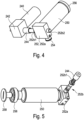
- the motor 240 has a gear 242 and an internally threaded interface 244.
- the pressure tank 250 has a valve 252, which has a valve housing 252a and a valve pin 252b. Furthermore, the pressure tank 250 has a gas outlet 254, an end piece 256, in particular a welded-on end piece, and a self-sealing filling screw 258.
- the pressure tank 250 is filled with air, which is pressurized to 200 bar.
- the pressure tank 250 is approved for a maximum pressure of at least twice the pressure actually used. In this way, the safety of the device 1, in particular against undesired gas escape, can be further improved.
- the valve housing 252 is connected to the pressure tank 250 in a gas-conducting manner at one end and is connected to the floating body 310 in a gas-conducting manner at the other end via the gas outlet 254.
- the valve pin 252b has an external thread interface 252b1 and the lock 252b2.
- the motor 240 is connected to the transmission 242 in a force-transmitting or torque-transmitting manner.
- the transmission 242 is intended to redirect the direction of the torque generated by the motor 240 at an angle of substantially 90 °, and in particular to reduce the speed provided by the motor 240.
- the rotational movement modified in direction and/or speed is transmitted to the internal thread interface 244.
- the internal thread interface 244 is connected to the external thread interface of the valve pin 252b engaged.
- the valve pin 252b is mounted in the valve housing in such a way that only a translational movement of the valve pin 252b is permitted. In particular, the valve pin 252b is prevented from rotating about its longitudinal axis by a tongue and groove connection.
- the rotational movement of the motor 240 produces a rotational movement of the internally threaded interface 244, which is intended to translate the valve pin 252b along its longitudinal axis.
- valve pin 252b moves over the threaded teeth in the valve housing 252a that are in engagement with each other, similar to a commercial vice, where a rotation of a nut with its degrees of freedom restricted also induces a movement of the movable holding jaw.
- the valve pin 252b fulfills two tasks: on the one hand, its original task, namely closing or opening the valve 252 and, on the other hand, locking or releasing the common unit detachably connected to the carrier device 100.
- the locking device 252b of the valve pin 252 engages in a recess in the carrier device 100 and thus fixes the common unit, in particular in a form-fitting manner, on the carrier device 100.
- valve pin 252b closes the pressure container 250 and one end of the valve pin, which serves as a lock 252b2, is inserted into the recess in the carrier device 100, whereby the common unit 200, 300 is on the carrier device 100 is fixed.
- the motor 240 moves the valve pin 252b in the manner described above, as a result of which one end of the valve pin, which serves as a lock 252b2, is pulled out of the recess in the carrier device 100, whereby the common unit detaches from the carrier device 100.
- the valve pin 252b releases the gas-conducting connection between the pressure tank 250 and the floating body 310.
- the air in the pressure tank 250 expands into the floating body 310, in particular a balloon made of latex, which has a diameter of 5 to 15 cm and a signal color.
- the floating body fills and pulls the common unit, which is non-detachably connected to the floating body via the gas outlet, upwards to the water surface.
- the common unit in particular the ferroelectric oscillating body 320, begins to emit an audio signal with a frequency in the range from 2 kHz to 10 kHz and a volume of approximately 100 decibels .
- the display 210 shows information about the set limit values regarding maximum depth and maximum duration, as well as information about the state of charge of the battery 220 and the operational readiness of the device 1, in particular about direct or indirect information about the internal pressure in the pressure tank 250.
- the display 210 also serves to display further information, such as the account balance of a cashless payment system or the locker number or remaining bathing time.
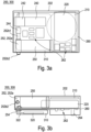
- FIG. 3a and 3b is a partially transparent schematic top view or a side view of the common unit consisting of monitoring device and reporting device Fig. 2 shown.
- circuit board 260 On the circuit board 260 are the display 210, the battery 220, the motor 240 with gear 242 internal thread interface 244, the pressure tank 250 with valve 252, having the valve housing 252a and the valve pin 252b, the gas outlet 254, various electrical and / or electronic components 262 , in particular a central processing unit (CPU), the pressure sensor device 264, the floating body 310, the ferroelectric oscillating body 320 and connecting lines 322 of the ferroelectric oscillating body 320 are arranged.
- CPU central processing unit
- a commercially available button cell is used as battery 220.
- the ferroelectric oscillating body 320 is electrically conductively connected to the signaling device 300 and/or the monitoring device 200 via the connecting lines 322.
- the ferroelectric oscillating body 320 is arranged within the floating body 310 in order to be able to use it as a sound body in the event of danger.
- the casting compound 202 extends around the common unit.
- the floating body 310 and the ferroelectric oscillating body 320 as well as the locking device 252b2 and at least part of a pressure sensor device 264, in particular the measuring sensor, are not enclosed by the casting compound 202.
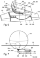
- Fig. 7 shows a partially transparent schematic three-dimensional view of the common unit 200, 300 consisting of monitoring device 200 and reporting device 300 of device 1 Fig. 1 , whereby the common unit 200, 300 with inflated floating body 310 is located on the water surface 20.
- the floating body 310 is dimensioned in such a way that it is able to transport the reporting device 300 and the monitoring device 200 to the water surface 20 and hold them there, in particular in such a way that a part of the floating body 310, in particular more than 50% of the Floating body 310, which is kept in a signal color, in particular red.
- the signaling device 300 begins via the ferroelectric oscillating body 320, which uses the floating body 310 as a resonance body and is supplied with energy by the battery 220, an acoustic signal with a frequency of 4 kHz and a volume of 100 decibels is emitted.
- This acoustic signal is supported by the floating body 310 on the water surface 20, which is kept in one or more signal colors, with regard to the location of the injured bather.
- Fig. 8 shows a modification of the first embodiment of the common unit described above, which is related to the embodiment of Figures 1, 2 , 4, 5 and 6 was explained. All of the above statements also apply in the same way to this modification of the first embodiment, unless otherwise follows from the following statements.
- the common unity of the Fig. 8 differs from the common unit described above Figures 1, 2 , 4, 5 and 6 that the pressure tank 250, the valve housing 252a and parts of the valve pin 252b are not enclosed by the casting compound 202.
- This has the advantage that in the event of an undesirable gas escape from the pressure tank 250, in particular in the form of a leak, the escaping gas does not flow into the casting compound 202 and damage it, but is released into the environment without further damage to the device 1.
- this design is advantageous because the pressure tank 250 is more easily accessible in the event of a scheduled or unscheduled overhaul.
- the common unit is preferably covered by a protective cover (not shown) in the event of no danger.
- the motor 240 can also be aligned with the valve pin 252b, so that a gear 242 can be dispensed with.
- a linear drive in particular a stepper motor, can also be provided, which is connected directly to the valve pin 252b in a force-transmitting manner in order to move it.
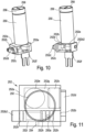
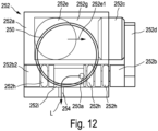
- Fig. 9 , 10 , 11 and 12 show partially transparent schematic three-dimensional views of a pressure tank 250 with a valve 252 according to a second embodiment of the present invention in a state before ( Fig. 9 and 11 ) or after ( Fig. 10 and 12 ) a triggering of a pyrotechnic device 252e from different perspectives. All of the above statements regarding the first embodiment also apply to the second embodiment in the same way, unless the following statements indicate otherwise.
- the second embodiment of the present invention differs from the first embodiment essentially in that the movement of the valve pin 252b is not caused by a motor 240, but by a pyrotechnic device 252e.
- the components motor 240, gearbox 242, internal thread interface 244 and the external thread interface 252b1 of the valve pin 252b are omitted.
- the pyrotechnic device 252e is arranged within the valve housing 252a in a first pressure channel 252g, wherein the valve housing 252a is preferably essentially gas-tight, in particular gas-tight, with respect to air with a pressure of up to 1,000 bar.
- the pyrotechnic device 252e is electrically conductively connected to the monitoring device 200, in particular to the battery 220, via a contacting device 252f.
- the pyrotechnic device 252e is further connected via the first pressure channel 252g in a gas-carrying manner to an actuator device 252c, in particular in the form of a Teflon-containing piston, such that the gas produced when the pyrotechnic device 252e is ignited exerts a force on the actuator device 252c in the direction of propagation 252e1 exercises, which is sufficient Actuator device 252c in at least one predetermined direction of movement, in particular a longitudinal axis of the actuator device 252c.
- the actuator device 252c is further connected to the valve pin 252b via a power transmission device 252d.
- the longitudinal axis of the valve pin 252b and the Teflon-containing piston 252c are aligned at least substantially parallel, in particular parallel, to one another.
- the force transmission device 252d is arranged outside the valve housing 252a and connects the valve pin 252b to the actuator device 252c in such a way that a movement of the actuator device 252c in the axial direction, in particular in the direction out of the valve housing 252a, is transmitted to the valve pin 252a, so that this moves at least substantially identically, in particular identically, with the actuator device 252c.
- the actuator device 252c is at least substantially completely, in particular completely, sunk into the valve housing 252a.
- the valve pin 252b closes the pressure vessel 250 in the initial situation (ie no danger is detected) and one end of the valve pin 252b, which serves as a lock 252b2, is inserted into the recess in the carrier device 100 (in Fig. 9 to 12 not shown), whereby the common unit 200, 300 is fixed to the carrier device 100.
- the valve pin 252b is displaced as described below, whereby one end of the valve pin 252b, which serves as a lock 252b2, is pulled out of the recess in the carrier device 100, whereby the common unit detaches from the carrier device 100.
- the valve pin 252b releases the gas-conducting connection between the pressure tank 250 and the floating body 310.
- energy is transferred from the battery 220 to the pyrotechnic device 252e by the monitoring device 200.
- This is preferably an energy pulse at a voltage of 12 volts.
- the pyrotechnic device 252e is ignited by the energy pulse, ie a component of the pyrotechnic device 252e and/or a substance of the pyrotechnic device 252e or within the pyrotechnic device 252e burns off. This creates a gas which collects in the valve housing 252a and thus builds up a pressure which acts against the actuator device 252c.
- the actuator device 252c is due to the Pressure building up within the valve housing 252a is at least partially pressed out of the valve housing 252a.
- the actuator device 252c is connected to the valve pin 252b via the force transmission device 252d in such a way that the movement of the actuator device 252c is transmitted to the valve pin 252a, whereby it is also displaced in the lateral direction along its longitudinal axis.
- one end of the valve pin 252b which serves as a lock 252b2 is pulled out of the recess in the carrier device 100, whereby the common unit detaches from the carrier device 100.
- the valve pin 252b releases the gas-conducting connection L between the pressure tank 250 via the outlet of the pressure tank 250a and the gas outlet 254 to the floating body 310.
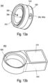
- FIG. 13a, 13b , 14, 15 and 16 a further embodiment of the device according to the invention is shown.
- This further embodiment differs from at least some of the previous ones in particular in that in the event of danger, not a common unit consisting of monitoring device 200 and reporting device 300 detaches from a carrier device 100, but rather that in case of danger, individual components of the monitoring device 200 remain in the carrier device 100, while others Components of the monitoring device 200 rise to the water surface 20 together with the reporting device 300. All of the above statements, in particular regarding the design and operation of the individual components, also apply to this further embodiment in the same way, unless otherwise emerges from the following statements and/or the relevant figures.
- the reporting device 300 together with the components of the monitoring device 200 described below, which rise to the water surface 20 together with the reporting device 300 in the event of danger, forms an alarm body 500.
- the carrier device 100 together with the components of the monitoring device 200 described below, which remain in the carrier device 100 in the event of danger, forms a basic device 600.
- Fig. 13a shows a schematic view of the alarm body 500, but without the floating body 310 (not shown).
- the alarm body 500 has: the pressure tank 250, the valve 252, in particular having the pyrotechnic device 252e, the floating body 310, a floating body holder 312 for attaching the Floating body 310, the ferroelectric oscillating body 320 and alarm body electronics 510.
- the alarm body electronics 510 has: a part of a plug-socket system (not shown) for electrically connecting the alarm body 500 to the base device 600, which is the complementary part of the plug-socket system. System (not shown).
- the alarm body electronics 510 has an independent energy supply in the form of the battery 220, in particular in the form of a button cell.
- the alarm body 500 can, according to a preferred embodiment, further have optoelectric components (not shown), in particular light-emitting diodes, in order to visually detect the effect of the audio signal generated by the ferroelectric oscillating body in the event of danger, in particular in the form of a light signal, in particular a flashing signal, preferably in the form of a flash-light-like signal generated at intervals.
- optoelectric components not shown, in particular light-emitting diodes, in order to visually detect the effect of the audio signal generated by the ferroelectric oscillating body in the event of danger, in particular in the form of a light signal, in particular a flashing signal, preferably in the form of a flash-light-like signal generated at intervals.
- the valve 252 is in the design of Fig. 13a integrated into the pressure tank 250 for the purpose of optimized space utilization.
- the operation of the valve 252 corresponds to the above statements regarding the other embodiments. Even if in the Fig. 13a the preferred variant of the pyrotechnic valve actuation is shown, it is of course possible to also implement the motor-driven valve actuation explained above in the alarm body 500.
- the gas released in the event of danger by the valve 252 flows through the gas outlet 254 (not shown), which is arranged, for example, near the inner edge of the floating body holder 312, into the floating body 310 and inflates it.
- the ferroelectric oscillating body 320 is in the design of Fig. 13a arranged behind the opening designated by the arrow 320, in particular on a circuit board of the alarm body electronics 510.
- the alarm body electronics 510 is intended, in particular designed, to open the valve 252 in response to a signal from the base device 600, so that the floating body 310 unfolds and the alarm body 500 detaches from the base device 600, as described in detail below, and rises to the water surface 20 and there by means of an audio signal, in particular the effect of which is supported by an optical signal, to draw attention to the dangerous situation.
- the energy for actuating the valve 252, in particular for igniting the pyrotechnic device 252e, can come from the battery 220 of the alarm body, or be provided by an energy storage device (not shown) of the base device 600, as described in detail below.
- the alarm body 500 is in the manner described above for the other embodiments via the lock 252b2 (in Fig. 13a not shown) fixed to the base device 600 by means of a recess (not shown) (see Fig. Fig. 14 ).
- the valve pin 252b is displaced in the manner described above, whereby one end of the valve pin, which serves as a lock 252b2, is pulled out of the recess in the base device 600, whereby the alarm body 500 detaches from the base device 600.
- the basic device 600 is in Fig. 13b shown.
- the base device 600 is intended to be worn, comparable to a watch, via a bracelet (not shown) on the arm, in particular on the wrist, of a person to be monitored.
- a bracelet not shown
- the base device 600 has a power supply that is independent of the alarm body 500, in particular a battery, preferably a rechargeable accumulator (not shown). Furthermore, the base device 600 has a wired, in particular wired, and/or wireless, in particular radio-based, such as WLAN, Bluetooth, etc., and/or light-based, in particular an infrared-based, interface for communication with an external data processing device, such as For example, a PC, a smartphone or the like. Data can be read out of the device via this interface and/or it can be configured in the manner described above, in particular using a device-specific program installed on the data processing device.
- the base device 600 also has the display 210 and base device electronics 610.
- the basic device electronics 610 has at least the following components described above, which are designed and act in a comparable manner here: the processor device, which is intended to fulfill at least part of the tasks of the processor device described above in the context of the other embodiments, if these cannot be taken over by the alarm body electronics 510; and the sensor device 264, in particular the pressure sensor device.
- the evaluation of the at least one sensor device 264 is carried out by the processor device of the base device 600. If this comes to the conclusion that there is a danger, it sends a signal to the alarm body 500, whereupon it detaches from the base device 600 in the manner described above.
- the base device 600 also has an alarm body receptacle 620, which is intended to accommodate the alarm body 500 at least partially in itself or according to an embodiment not shown in the event of no danger.
- the base device 600 is connected to the alarm body 500 in an electrically conductive manner.
- the alarm body electronics 510 can be supplied via the energy supply of the base device 600 in the event of no danger in order to protect the battery 220, which in this embodiment is at least essentially non-rechargeable.
- the charge level of the battery 220 of the alarm body 500 can also be monitored and communicated, for example, via the display 210.
- the energy supply of the base device 600 can be used to maintain the voltage of the battery 220, in particular to charge it when necessary.
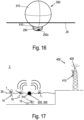
- the Figures 15 and 16 show the alarm body 500 in the event of danger, with the alarm body 500 in the Fig. 15 is still in the ascent phase to the water surface 20, while he is in the Fig. 16 has already arrived at the water surface 20.
- Fig. 17 shows a schematic representation of a system according to an embodiment of the present invention and an exemplary application in a swimming pool.
- Each person 10 to be monitored wears a device 1 on his wrist.
- At least one base station 400 which has a receiving device 410 and a transmitting device 420, is arranged in relation to the swimming pool in such a way that the Receiving device 410 is able to receive a signal from the device 1, in particular the reporting device 300.
- the reporting device 300 of the device 1 of the person 10 located on the pool floor sends out an audio signal so that the other bathing people 10 or people in the pool area (not shown) are made aware of the danger.
- the base station 400 detects the audio signal using its receiving device 410 and, using its transmitting device 420, also sends an emergency call to more distant locations, such as rescue stations and/or water stations and/or fire departments and/or police stations and/or medical emergency services.
- the transmitting device 420 can generate a further audio signal and/or visual signal, which also alerts people who are further away, for example at the edge of the pool, to the danger.
- Fig. 18 shows a schematic representation of a method for monitoring people in water according to an embodiment of the present invention, comprising the steps, in particular in the following order: S1 Attaching to a person a device for monitoring people in water of the type described above in various embodiments; S2 Detecting via the sensor device whether, in particular how deep, the person is in the water; S3 Detecting, via a time measuring device of the monitoring device, how long the person stays in the water, in particular below a predetermined depth; S4 Detecting a hazard as soon as the person stays in the water for longer than a predetermined period of time, in particular below a predetermined depth, in particular continuously; S5 at least partially, in particular completely, releasing the reporting device from the carrier device in response to a signal from the monitoring device; S6 The signaling device rises to the surface of the water.
- the method further comprises the step: S7 Emitting an audio signal and/or a visual signal and/or a radio signal through the reporting device.
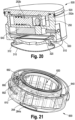
- FIG. 19 to 23 A further embodiment of a device according to the invention for monitoring people in the water 1 is shown, which has the alarm body 500 and the base device 600.
- the alarm body 500 is connected to the base device 600, in particular inserted into the alarm body receptacle 620 of the base device 600, with the floating body 310 not being shown.
- the alarm body 500 the Figures 19 and 20 has the pressure tank 250, which is formed by a recess within the alarm body 500 and in particular is further limited by a cover of the alarm body 500.
- the valve pin 252b in Fig. 19 has released a gas passage between pressure tank 250 and floating body 310, while this gas passage is in Fig. 20 is blocked by the valve pin 252b.
- the movement of the valve pin from the closed position ( Fig. 20 ) to the open position ( Fig. 19 ) is preferably designed to be reversible in a non-destructive manner.
- the movement of the valve pin 252b is caused by a pyrotechnic device 252e, which is ignited in the event of danger in response to a signal from the alarm body electronics 510.
- the gas released by ignition creates a force on the valve pin 252b, moving it from the closed position to the open position.
- Ignition is carried out by a signal from the alarm body electronics 510, which in the inserted state are connected to each other in a signal and/or energy-conducting manner with the basic device electronics 610 via electrical contacts 550, 650.
- the electrical contacts 550, 650 are preferably designed so that they are separated from one another in the event of danger, in particular if the alarm body 500 detaches from the base device 600.
- the sensor device 264 in particular in the form of a pressure sensor device, is arranged in the base device 600. Either the measurement data is transmitted to the alarm body 500 and the depth and time are monitored via the alarm body electronics 510 and in the event of danger, a control signal is transmitted to the alarm body electronics 510, which in turn causes the pyrotechnic device 252e to be ignited.
- the alarm body 500 is supplied with energy, particularly in the event of danger after separation from the base device 600, via its own battery 540.
- the base device 600 is supplied with energy, particularly in the event of danger after the alarm body 500 has been separated, via its own battery 640.
- the alarm body 500 is designed to separate from the base device 600 in the event of danger by using an increasing volume of the floating body 310 during the transfer of the floating body 310 into the buoyant state during inflation, a force against a part of the base device 600, in particular a base plate, the force causing a separation of the alarm body 500 from the base device 600.
- the floating body 310 is held on the alarm body 500 by a floating body holder 312.
- the ferroelectric oscillating body 320 is connected to an interior of the floating body 310 in a gas-carrying manner. In this way, the sound generated by the ferromagnetic oscillating body 320 is emitted via the floating body 310 at least partially above the water surface.
- the alarm body 500 When inserted, the alarm body 500 is sealed from the base device 600 by means of a sealing device 520, in particular a sealing ring.
- a sealing device 520 in particular a sealing ring.
- individual components or assemblies of the base device 600 can be sealed against one another via a sealing device 630, in particular a sealing ring.
- the base device 600 has a, in particular slot-like, passage which fluidly connects the sensor device 264 with the environment, in particular the water surrounding the device 1.
- the sensor device 264 is at least essentially protected from unwanted physical influences, such as dirt and/or shocks, while the detection of the parameter to be detected, in particular the ambient pressure as a measure of the water depth, is made possible.
- the device 1 can be connected, at least temporarily, to an external control device (not shown), such as a personal computer, via a multi-pole, in particular 4-pole, contact.
- an external control device such as a personal computer
- limit values for depth and/or maximum time duration below the depth limit can be adjusted according to the level of the person to be monitored and/or data, in particular depth/time profiles, can be read out or the like.
- a connecting line 700 with a connecting device 710 is held on the base device 600 by means of a, in particular magnetic, locking device 662 during the connection to the external control device.
- the base device 600 also has a localization device 330 in the form of an LED, in particular a high-performance LED, which preferably emits a flashing light signal in the event of danger.
- a localization device 330 in the form of an LED, in particular a high-performance LED, which preferably emits a flashing light signal in the event of danger.
Landscapes
- Physics & Mathematics (AREA)
- General Physics & Mathematics (AREA)
- Business, Economics & Management (AREA)
- Emergency Management (AREA)
- Health & Medical Sciences (AREA)
- Child & Adolescent Psychology (AREA)
- General Health & Medical Sciences (AREA)
- Engineering & Computer Science (AREA)
- Human Computer Interaction (AREA)
- Emergency Alarm Devices (AREA)
- Alarm Systems (AREA)
Applications Claiming Priority (2)
| Application Number | Priority Date | Filing Date | Title |
|---|---|---|---|
| DE102015011085.3A DE102015011085A1 (de) | 2015-08-24 | 2015-08-24 | Vorrichtung und Verfahren zum Schutz vor Badeunfällen, insbesondere zum frühzeitigen Erkennen von Ertrinkenden, und dergleichen |
| PCT/EP2016/069845 WO2017032757A1 (de) | 2015-08-24 | 2016-08-23 | Vorrichtung und verfahren zum schutz vor badeunfällen, insbesondere zum frühzeitigen erkennen von ertrinkenden, und dergleichen |
Publications (3)
| Publication Number | Publication Date |
|---|---|
| EP3341922A1 EP3341922A1 (de) | 2018-07-04 |
| EP3341922B1 true EP3341922B1 (de) | 2023-11-22 |
| EP3341922C0 EP3341922C0 (de) | 2023-11-22 |
Family
ID=56851566
Family Applications (1)
| Application Number | Title | Priority Date | Filing Date |
|---|---|---|---|
| EP16758129.7A Active EP3341922B1 (de) | 2015-08-24 | 2016-08-23 | Vorrichtung und verfahren zum schutz vor badeunfällen, insbesondere zum frühzeitigen erkennen von ertrinkenden, und dergleichen |
Country Status (7)
| Country | Link |
|---|---|
| US (1) | US10692348B2 (enExample) |
| EP (1) | EP3341922B1 (enExample) |
| JP (1) | JP7195926B2 (enExample) |
| CN (1) | CN108352104A (enExample) |
| AU (1) | AU2016313075B2 (enExample) |
| DE (1) | DE102015011085A1 (enExample) |
| WO (1) | WO2017032757A1 (enExample) |
Families Citing this family (13)
| Publication number | Priority date | Publication date | Assignee | Title |
|---|---|---|---|---|
| DE102017110944A1 (de) * | 2017-05-19 | 2018-11-22 | Bernd Drexler | Sicherheits-Vorrichtung für Schwimmarealnutzer |
| CN107590957A (zh) * | 2017-08-23 | 2018-01-16 | 广东小天才科技有限公司 | 一种报警方法、装置和可穿戴设备 |
| CN107331124B (zh) * | 2017-08-23 | 2021-04-13 | 芜湖博格信息科技有限公司 | 智能穿戴防溺水传感设备 |
| JP2020019424A (ja) * | 2018-08-02 | 2020-02-06 | スズキ株式会社 | 救難信号発信システム |
| CN109341669A (zh) * | 2018-10-31 | 2019-02-15 | 广东小天才科技有限公司 | 水深测量方法及装置 |
| KR102295301B1 (ko) * | 2019-08-13 | 2021-08-30 | 비앤피이노베이션 주식회사 | 익사 방지 웨어러블 디바이스 및 이의 제어방법 |
| KR102214950B1 (ko) * | 2020-08-21 | 2021-02-10 | (주)유니락서비스 | 분리 구조의 위험 신호 발생기 |
| CN112309077A (zh) * | 2020-09-23 | 2021-02-02 | 苏宁云计算有限公司 | 一种泳池溺水警报方法及装置 |
| US12288457B2 (en) | 2020-12-04 | 2025-04-29 | Wearable Technologies Inc. | Smart wearable personal safety devices and related systems and methods |
| PL438432A1 (pl) * | 2021-07-09 | 2022-01-17 | Berserg Spółka Z Ograniczoną Odpowiedzialnością | Układ opaski/bransolety użytkownika obiektów z basenami wodnymi generujący sygnał alarmu zagrożenia stanu użytkownika i sposób jego wytworzenia. |
| US11756405B2 (en) | 2021-07-26 | 2023-09-12 | Matthew ZELLMAN | Submersion sensor |
| DE102021122544B3 (de) | 2021-08-31 | 2023-02-09 | Hahn-Schickard-Gesellschaft für angewandte Forschung e.V. | Miniaturisierte pyrotechnisch induzierte schallerzeugung |
| KR102868606B1 (ko) * | 2025-04-09 | 2025-10-14 | 주식회사 4더피플 | 블루투스 통신 기반의 수중 저산소성 블랙아웃 모니터링 시스템 |
Citations (1)
| Publication number | Priority date | Publication date | Assignee | Title |
|---|---|---|---|---|
| ES1068634U (es) * | 2008-09-02 | 2008-11-01 | Scio Soft, S.L. | Dispositivo de emergencia perfeccionado, aplicable en embarcaciones de pequeña eslora, para aviso y localizacion de personas. |
Family Cites Families (24)
| Publication number | Priority date | Publication date | Assignee | Title |
|---|---|---|---|---|
| JPS61229692A (ja) | 1985-04-04 | 1986-10-13 | Mitsubishi Heavy Ind Ltd | 潜水物体用浮上装置 |
| US4929214A (en) * | 1987-11-02 | 1990-05-29 | Liebermann Ron B | Inflatable enclosure and means to inflate same |
| FR2638366A1 (fr) | 1988-10-28 | 1990-05-04 | Thomson Csf | Systeme de prevention des noyades accidentelles |
| JPH02214888A (ja) | 1989-02-16 | 1990-08-27 | Seikosha Co Ltd | 可変色発音装置 |
| JPH03213494A (ja) | 1990-01-12 | 1991-09-18 | Liebermann Ronald | 膨張式密閉体製品 |
| US5520486A (en) * | 1994-09-09 | 1996-05-28 | Van Wyck; William | Diver safety apparatus and method |
| DE10116000A1 (de) | 2000-03-28 | 2002-10-02 | Hans-Peter Klein | Überwachungssytem zur Vermeidung von Unfällen durch Ertrinken |
| AUPS058202A0 (en) | 2002-02-15 | 2002-03-14 | Tsitas, Steven | Marine security device |
| JP4129380B2 (ja) * | 2002-09-11 | 2008-08-06 | 日本救命器具株式会社 | 救命具 |
| EP1492069A1 (fr) | 2003-06-26 | 2004-12-29 | Jean-Pierre Borer | Dispositif d'assistance à la surveillance d'une piscine |
| IL172979A0 (en) * | 2006-01-04 | 2006-06-11 | Weintraub Eitan | Apparatus and method for the early detection of a person in drowning or near-drowning situation |
| US7267509B1 (en) * | 2006-05-01 | 2007-09-11 | Jackson Iii William H | Floatation device |
| SE532177C2 (sv) | 2006-07-24 | 2009-11-10 | P & P Ab | En punkteringsanordning för en uppblåsbar enhet |
| PT1918191E (pt) * | 2006-11-06 | 2009-04-03 | Juergen Puls | Processo e equipamento para reconhecer o perigo de afogamento de uma pessoa dentro de água |
| US7554453B2 (en) * | 2006-12-22 | 2009-06-30 | Thermocline Ventures Llc | Water alarm devices, systems and related methods |
| US8205101B2 (en) * | 2008-04-18 | 2012-06-19 | Rockwell Automation Technologies, Inc. | On-machine power supply with integral coupling features |
| DE102008050558A1 (de) | 2008-10-06 | 2010-04-08 | Bluearc Finance Ag | Vorrichtung und Verfahren zur Überwachung von Gewässern |
| US20130171894A1 (en) | 2010-09-16 | 2013-07-04 | Zactill Intellectual Property Pty Ltd | Safety Device and Inflating Apparatus Therefor |
| CN103440735B (zh) * | 2013-09-17 | 2016-03-02 | 北京海豚光波科技开发有限公司 | 一种游泳池溺水救生智能系统 |
| CN203503115U (zh) * | 2013-09-25 | 2014-03-26 | 成都环益卓越泳池设备有限公司 | 游泳安全防护系统 |
| US9868495B2 (en) * | 2013-12-11 | 2018-01-16 | Safe Swim Ltd. | Controllable water floatation garment |
| CN103818532B (zh) * | 2014-03-03 | 2016-08-17 | 何光 | 游泳或水中遇险时所用的救生安全带 |
| CN104590509A (zh) * | 2014-12-10 | 2015-05-06 | 宁波一舟精密机械制造有限公司 | 水中救生器 |
| CN104824926A (zh) | 2015-04-29 | 2015-08-12 | 苏州骄子信息科技有限公司 | 一种防溺水通信手环 |
-
2015
- 2015-08-24 DE DE102015011085.3A patent/DE102015011085A1/de not_active Withdrawn
-
2016
- 2016-08-23 AU AU2016313075A patent/AU2016313075B2/en active Active
- 2016-08-23 US US15/754,655 patent/US10692348B2/en active Active
- 2016-08-23 EP EP16758129.7A patent/EP3341922B1/de active Active
- 2016-08-23 WO PCT/EP2016/069845 patent/WO2017032757A1/de not_active Ceased
- 2016-08-23 CN CN201680062262.8A patent/CN108352104A/zh active Pending
- 2016-08-23 JP JP2018529724A patent/JP7195926B2/ja active Active
Patent Citations (1)
| Publication number | Priority date | Publication date | Assignee | Title |
|---|---|---|---|---|
| ES1068634U (es) * | 2008-09-02 | 2008-11-01 | Scio Soft, S.L. | Dispositivo de emergencia perfeccionado, aplicable en embarcaciones de pequeña eslora, para aviso y localizacion de personas. |
Also Published As
| Publication number | Publication date |
|---|---|
| WO2017032757A1 (de) | 2017-03-02 |
| US20180240320A1 (en) | 2018-08-23 |
| JP7195926B2 (ja) | 2022-12-26 |
| AU2016313075B2 (en) | 2022-03-03 |
| JP2018530088A (ja) | 2018-10-11 |
| DE102015011085A1 (de) | 2017-03-02 |
| US10692348B2 (en) | 2020-06-23 |
| AU2016313075A1 (en) | 2018-03-22 |
| EP3341922C0 (de) | 2023-11-22 |
| EP3341922A1 (de) | 2018-07-04 |
| CN108352104A (zh) | 2018-07-31 |
Similar Documents
| Publication | Publication Date | Title |
|---|---|---|
| EP3341922B1 (de) | Vorrichtung und verfahren zum schutz vor badeunfällen, insbesondere zum frühzeitigen erkennen von ertrinkenden, und dergleichen | |
| EP1918191B1 (de) | Verfahren und Einrichtung zum Erkennen der Ertrinkungsgefahr für eine Person im Wasser | |
| DE102008050558A1 (de) | Vorrichtung und Verfahren zur Überwachung von Gewässern | |
| EP3038897B1 (de) | Aktivierungsvorrichtung zur auslösung von automatischem rettungsmittel | |
| AU2011262227B2 (en) | Methods and devices for rescuing a distressed diver | |
| EP2839594B1 (de) | Signaleinrichtung für taucher | |
| DE202007006819U1 (de) | System zur Rettung von Personen vor dem Ertrinken | |
| US10773779B2 (en) | Control device | |
| DE102017115297B4 (de) | Aufblasvorrichtung und Wasserrettungseinrichtung | |
| DE3016383C2 (de) | Sicherheitsvorrichtung für einen Aufenthalt einer Person bei einem nichtatmosphärischen Druck, insbesondere für Taucher | |
| CN205751155U (zh) | 水中报警手环内的气体生成装置 | |
| CN203720993U (zh) | 溺水报警装置 | |
| CN105015734A (zh) | 水下急救压缩空气释放装置 | |
| DE202013001652U1 (de) | Seenotsignaleinrichtung | |
| AT8650U1 (de) | Vorrichtung zum aussenden von alarmsignalen bei ertrinkungsgefahr | |
| JPS6165395A (ja) | 水難時救急警報器具 |
Legal Events
| Date | Code | Title | Description |
|---|---|---|---|
| STAA | Information on the status of an ep patent application or granted ep patent |
Free format text: STATUS: THE INTERNATIONAL PUBLICATION HAS BEEN MADE |
|
| PUAI | Public reference made under article 153(3) epc to a published international application that has entered the european phase |
Free format text: ORIGINAL CODE: 0009012 |
|
| STAA | Information on the status of an ep patent application or granted ep patent |
Free format text: STATUS: REQUEST FOR EXAMINATION WAS MADE |
|
| 17P | Request for examination filed |
Effective date: 20180323 |
|
| AK | Designated contracting states |
Kind code of ref document: A1 Designated state(s): AL AT BE BG CH CY CZ DE DK EE ES FI FR GB GR HR HU IE IS IT LI LT LU LV MC MK MT NL NO PL PT RO RS SE SI SK SM TR |
|
| AX | Request for extension of the european patent |
Extension state: BA ME |
|
| DAV | Request for validation of the european patent (deleted) | ||
| DAX | Request for extension of the european patent (deleted) | ||
| STAA | Information on the status of an ep patent application or granted ep patent |
Free format text: STATUS: EXAMINATION IS IN PROGRESS |
|
| 17Q | First examination report despatched |
Effective date: 20200508 |
|
| GRAP | Despatch of communication of intention to grant a patent |
Free format text: ORIGINAL CODE: EPIDOSNIGR1 |
|
| STAA | Information on the status of an ep patent application or granted ep patent |
Free format text: STATUS: GRANT OF PATENT IS INTENDED |
|
| INTG | Intention to grant announced |
Effective date: 20230621 |
|
| GRAS | Grant fee paid |
Free format text: ORIGINAL CODE: EPIDOSNIGR3 |
|
| GRAA | (expected) grant |
Free format text: ORIGINAL CODE: 0009210 |
|
| STAA | Information on the status of an ep patent application or granted ep patent |
Free format text: STATUS: THE PATENT HAS BEEN GRANTED |
|
| AK | Designated contracting states |
Kind code of ref document: B1 Designated state(s): AL AT BE BG CH CY CZ DE DK EE ES FI FR GB GR HR HU IE IS IT LI LT LU LV MC MK MT NL NO PL PT RO RS SE SI SK SM TR |
|
| REG | Reference to a national code |
Ref country code: GB Ref legal event code: FG4D Free format text: NOT ENGLISH |
|
| REG | Reference to a national code |
Ref country code: CH Ref legal event code: EP Ref country code: DE Ref legal event code: R096 Ref document number: 502016016233 Country of ref document: DE |
|
| REG | Reference to a national code |
Ref country code: IE Ref legal event code: FG4D Free format text: LANGUAGE OF EP DOCUMENT: GERMAN |
|
| U01 | Request for unitary effect filed |
Effective date: 20231206 |
|
| U07 | Unitary effect registered |
Designated state(s): AT BE BG DE DK EE FI FR IT LT LU LV MT NL PT SE SI Effective date: 20231212 |
|
| PG25 | Lapsed in a contracting state [announced via postgrant information from national office to epo] |
Ref country code: GR Free format text: LAPSE BECAUSE OF FAILURE TO SUBMIT A TRANSLATION OF THE DESCRIPTION OR TO PAY THE FEE WITHIN THE PRESCRIBED TIME-LIMIT Effective date: 20240223 |
|
| PG25 | Lapsed in a contracting state [announced via postgrant information from national office to epo] |
Ref country code: IS Free format text: LAPSE BECAUSE OF FAILURE TO SUBMIT A TRANSLATION OF THE DESCRIPTION OR TO PAY THE FEE WITHIN THE PRESCRIBED TIME-LIMIT Effective date: 20240322 |
|
| PG25 | Lapsed in a contracting state [announced via postgrant information from national office to epo] |
Ref country code: ES Free format text: LAPSE BECAUSE OF FAILURE TO SUBMIT A TRANSLATION OF THE DESCRIPTION OR TO PAY THE FEE WITHIN THE PRESCRIBED TIME-LIMIT Effective date: 20231122 |
|
| PG25 | Lapsed in a contracting state [announced via postgrant information from national office to epo] |
Ref country code: IS Free format text: LAPSE BECAUSE OF FAILURE TO SUBMIT A TRANSLATION OF THE DESCRIPTION OR TO PAY THE FEE WITHIN THE PRESCRIBED TIME-LIMIT Effective date: 20240322 Ref country code: GR Free format text: LAPSE BECAUSE OF FAILURE TO SUBMIT A TRANSLATION OF THE DESCRIPTION OR TO PAY THE FEE WITHIN THE PRESCRIBED TIME-LIMIT Effective date: 20240223 Ref country code: ES Free format text: LAPSE BECAUSE OF FAILURE TO SUBMIT A TRANSLATION OF THE DESCRIPTION OR TO PAY THE FEE WITHIN THE PRESCRIBED TIME-LIMIT Effective date: 20231122 |
|
| PG25 | Lapsed in a contracting state [announced via postgrant information from national office to epo] |
Ref country code: RS Free format text: LAPSE BECAUSE OF FAILURE TO SUBMIT A TRANSLATION OF THE DESCRIPTION OR TO PAY THE FEE WITHIN THE PRESCRIBED TIME-LIMIT Effective date: 20231122 Ref country code: PL Free format text: LAPSE BECAUSE OF FAILURE TO SUBMIT A TRANSLATION OF THE DESCRIPTION OR TO PAY THE FEE WITHIN THE PRESCRIBED TIME-LIMIT Effective date: 20231122 Ref country code: NO Free format text: LAPSE BECAUSE OF FAILURE TO SUBMIT A TRANSLATION OF THE DESCRIPTION OR TO PAY THE FEE WITHIN THE PRESCRIBED TIME-LIMIT Effective date: 20240222 Ref country code: HR Free format text: LAPSE BECAUSE OF FAILURE TO SUBMIT A TRANSLATION OF THE DESCRIPTION OR TO PAY THE FEE WITHIN THE PRESCRIBED TIME-LIMIT Effective date: 20231122 |
|
| PG25 | Lapsed in a contracting state [announced via postgrant information from national office to epo] |
Ref country code: CZ Free format text: LAPSE BECAUSE OF FAILURE TO SUBMIT A TRANSLATION OF THE DESCRIPTION OR TO PAY THE FEE WITHIN THE PRESCRIBED TIME-LIMIT Effective date: 20231122 |
|
| PG25 | Lapsed in a contracting state [announced via postgrant information from national office to epo] |
Ref country code: SK Free format text: LAPSE BECAUSE OF FAILURE TO SUBMIT A TRANSLATION OF THE DESCRIPTION OR TO PAY THE FEE WITHIN THE PRESCRIBED TIME-LIMIT Effective date: 20231122 |
|
| PG25 | Lapsed in a contracting state [announced via postgrant information from national office to epo] |
Ref country code: SM Free format text: LAPSE BECAUSE OF FAILURE TO SUBMIT A TRANSLATION OF THE DESCRIPTION OR TO PAY THE FEE WITHIN THE PRESCRIBED TIME-LIMIT Effective date: 20231122 Ref country code: SK Free format text: LAPSE BECAUSE OF FAILURE TO SUBMIT A TRANSLATION OF THE DESCRIPTION OR TO PAY THE FEE WITHIN THE PRESCRIBED TIME-LIMIT Effective date: 20231122 Ref country code: RO Free format text: LAPSE BECAUSE OF FAILURE TO SUBMIT A TRANSLATION OF THE DESCRIPTION OR TO PAY THE FEE WITHIN THE PRESCRIBED TIME-LIMIT Effective date: 20231122 Ref country code: CZ Free format text: LAPSE BECAUSE OF FAILURE TO SUBMIT A TRANSLATION OF THE DESCRIPTION OR TO PAY THE FEE WITHIN THE PRESCRIBED TIME-LIMIT Effective date: 20231122 |
|
| REG | Reference to a national code |
Ref country code: DE Ref legal event code: R097 Ref document number: 502016016233 Country of ref document: DE |
|
| U20 | Renewal fee for the european patent with unitary effect paid |
Year of fee payment: 9 Effective date: 20240814 |
|
| PLBE | No opposition filed within time limit |
Free format text: ORIGINAL CODE: 0009261 |
|
| STAA | Information on the status of an ep patent application or granted ep patent |
Free format text: STATUS: NO OPPOSITION FILED WITHIN TIME LIMIT |
|
| PGFP | Annual fee paid to national office [announced via postgrant information from national office to epo] |
Ref country code: GB Payment date: 20240822 Year of fee payment: 9 |
|
| PGFP | Annual fee paid to national office [announced via postgrant information from national office to epo] |
Ref country code: CH Payment date: 20240901 Year of fee payment: 9 |
|
| 26N | No opposition filed |
Effective date: 20240823 |
|
| PG25 | Lapsed in a contracting state [announced via postgrant information from national office to epo] |
Ref country code: MC Free format text: LAPSE BECAUSE OF FAILURE TO SUBMIT A TRANSLATION OF THE DESCRIPTION OR TO PAY THE FEE WITHIN THE PRESCRIBED TIME-LIMIT Effective date: 20231122 |
|
| PG25 | Lapsed in a contracting state [announced via postgrant information from national office to epo] |
Ref country code: IE Free format text: LAPSE BECAUSE OF NON-PAYMENT OF DUE FEES Effective date: 20240823 |