EP3341922B1 - Device and method for protecting against swimming accidents, in particularl for the early detection of drowning persons, and the like - Google Patents
Device and method for protecting against swimming accidents, in particularl for the early detection of drowning persons, and the like Download PDFInfo
- Publication number
- EP3341922B1 EP3341922B1 EP16758129.7A EP16758129A EP3341922B1 EP 3341922 B1 EP3341922 B1 EP 3341922B1 EP 16758129 A EP16758129 A EP 16758129A EP 3341922 B1 EP3341922 B1 EP 3341922B1
- Authority
- EP
- European Patent Office
- Prior art keywords
- signal
- water
- monitoring
- person
- gas
- Prior art date
- Legal status (The legal status is an assumption and is not a legal conclusion. Google has not performed a legal analysis and makes no representation as to the accuracy of the status listed.)
- Active
Links
- 238000000034 method Methods 0.000 title claims description 13
- 206010013647 Drowning Diseases 0.000 title claims description 7
- 238000001514 detection method Methods 0.000 title claims description 6
- 230000009182 swimming Effects 0.000 title description 16
- XLYOFNOQVPJJNP-UHFFFAOYSA-N water Substances O XLYOFNOQVPJJNP-UHFFFAOYSA-N 0.000 claims description 143
- 239000007789 gas Substances 0.000 claims description 58
- 238000012806 monitoring device Methods 0.000 claims description 55
- 238000012544 monitoring process Methods 0.000 claims description 33
- 230000004044 response Effects 0.000 claims description 31
- 230000011664 signaling Effects 0.000 claims description 30
- 230000005236 sound signal Effects 0.000 claims description 25
- 239000000126 substance Substances 0.000 claims description 18
- 230000001681 protective effect Effects 0.000 claims description 14
- 230000000007 visual effect Effects 0.000 claims description 12
- 239000007788 liquid Substances 0.000 claims description 8
- 238000012546 transfer Methods 0.000 claims description 6
- 239000000843 powder Substances 0.000 claims description 4
- QVGXLLKOCUKJST-UHFFFAOYSA-N atomic oxygen Chemical compound [O] QVGXLLKOCUKJST-UHFFFAOYSA-N 0.000 claims description 2
- 239000001301 oxygen Substances 0.000 claims description 2
- 229910052760 oxygen Inorganic materials 0.000 claims description 2
- 239000007787 solid Substances 0.000 claims description 2
- 238000005188 flotation Methods 0.000 claims 12
- 230000000630 rising effect Effects 0.000 claims 1
- 238000007667 floating Methods 0.000 description 77
- 230000033001 locomotion Effects 0.000 description 14
- 238000007789 sealing Methods 0.000 description 10
- 210000000707 wrist Anatomy 0.000 description 9
- 230000005540 biological transmission Effects 0.000 description 8
- 150000001875 compounds Chemical class 0.000 description 7
- 238000005266 casting Methods 0.000 description 6
- 238000013461 design Methods 0.000 description 6
- 230000000694 effects Effects 0.000 description 5
- ATUOYWHBWRKTHZ-UHFFFAOYSA-N Propane Chemical compound CCC ATUOYWHBWRKTHZ-UHFFFAOYSA-N 0.000 description 4
- 238000003287 bathing Methods 0.000 description 4
- 230000006378 damage Effects 0.000 description 4
- 230000006870 function Effects 0.000 description 4
- 230000004807 localization Effects 0.000 description 4
- 238000012986 modification Methods 0.000 description 4
- 230000004048 modification Effects 0.000 description 4
- 238000012545 processing Methods 0.000 description 4
- 238000000926 separation method Methods 0.000 description 4
- 230000008901 benefit Effects 0.000 description 3
- 238000011161 development Methods 0.000 description 3
- 230000018109 developmental process Effects 0.000 description 3
- 239000000463 material Substances 0.000 description 3
- 238000005259 measurement Methods 0.000 description 3
- 239000000203 mixture Substances 0.000 description 3
- 230000002829 reductive effect Effects 0.000 description 3
- 150000003839 salts Chemical class 0.000 description 3
- XKRFYHLGVUSROY-UHFFFAOYSA-N Argon Chemical compound [Ar] XKRFYHLGVUSROY-UHFFFAOYSA-N 0.000 description 2
- ZAMOUSCENKQFHK-UHFFFAOYSA-N Chlorine atom Chemical compound [Cl] ZAMOUSCENKQFHK-UHFFFAOYSA-N 0.000 description 2
- OTMSDBZUPAUEDD-UHFFFAOYSA-N Ethane Chemical compound CC OTMSDBZUPAUEDD-UHFFFAOYSA-N 0.000 description 2
- 208000006079 Near drowning Diseases 0.000 description 2
- 239000004809 Teflon Substances 0.000 description 2
- 229920006362 Teflon® Polymers 0.000 description 2
- 239000001273 butane Substances 0.000 description 2
- 239000002775 capsule Substances 0.000 description 2
- 239000000460 chlorine Substances 0.000 description 2
- 229910052801 chlorine Inorganic materials 0.000 description 2
- 239000003086 colorant Substances 0.000 description 2
- 238000006073 displacement reaction Methods 0.000 description 2
- 238000011156 evaluation Methods 0.000 description 2
- 230000005294 ferromagnetic effect Effects 0.000 description 2
- 230000036541 health Effects 0.000 description 2
- 238000007689 inspection Methods 0.000 description 2
- 239000004816 latex Substances 0.000 description 2
- 229920000126 latex Polymers 0.000 description 2
- IJDNQMDRQITEOD-UHFFFAOYSA-N n-butane Chemical compound CCCC IJDNQMDRQITEOD-UHFFFAOYSA-N 0.000 description 2
- OFBQJSOFQDEBGM-UHFFFAOYSA-N n-pentane Natural products CCCCC OFBQJSOFQDEBGM-UHFFFAOYSA-N 0.000 description 2
- 230000003287 optical effect Effects 0.000 description 2
- 230000036961 partial effect Effects 0.000 description 2
- 230000008569 process Effects 0.000 description 2
- 239000001294 propane Substances 0.000 description 2
- 230000001960 triggered effect Effects 0.000 description 2
- 239000003643 water by type Substances 0.000 description 2
- 241000282412 Homo Species 0.000 description 1
- FEWJPZIEWOKRBE-UHFFFAOYSA-N Tartaric acid Natural products [H+].[H+].[O-]C(=O)C(O)C(O)C([O-])=O FEWJPZIEWOKRBE-UHFFFAOYSA-N 0.000 description 1
- 208000003443 Unconsciousness Diseases 0.000 description 1
- 230000032683 aging Effects 0.000 description 1
- 229910052786 argon Inorganic materials 0.000 description 1
- 230000000712 assembly Effects 0.000 description 1
- 238000000429 assembly Methods 0.000 description 1
- 238000006243 chemical reaction Methods 0.000 description 1
- 238000004891 communication Methods 0.000 description 1
- 230000002860 competitive effect Effects 0.000 description 1
- 230000000295 complement effect Effects 0.000 description 1
- 238000013480 data collection Methods 0.000 description 1
- 230000001066 destructive effect Effects 0.000 description 1
- 238000007598 dipping method Methods 0.000 description 1
- 239000004815 dispersion polymer Substances 0.000 description 1
- 235000013399 edible fruits Nutrition 0.000 description 1
- 229920001971 elastomer Polymers 0.000 description 1
- 239000000806 elastomer Substances 0.000 description 1
- 238000005265 energy consumption Methods 0.000 description 1
- 238000004146 energy storage Methods 0.000 description 1
- 239000000945 filler Substances 0.000 description 1
- 239000001307 helium Substances 0.000 description 1
- 229910052734 helium Inorganic materials 0.000 description 1
- SWQJXJOGLNCZEY-UHFFFAOYSA-N helium atom Chemical compound [He] SWQJXJOGLNCZEY-UHFFFAOYSA-N 0.000 description 1
- 238000009434 installation Methods 0.000 description 1
- 229910052743 krypton Inorganic materials 0.000 description 1
- DNNSSWSSYDEUBZ-UHFFFAOYSA-N krypton atom Chemical compound [Kr] DNNSSWSSYDEUBZ-UHFFFAOYSA-N 0.000 description 1
- 230000005291 magnetic effect Effects 0.000 description 1
- 238000004519 manufacturing process Methods 0.000 description 1
- 230000005405 multipole Effects 0.000 description 1
- 229910052754 neon Inorganic materials 0.000 description 1
- GKAOGPIIYCISHV-UHFFFAOYSA-N neon atom Chemical compound [Ne] GKAOGPIIYCISHV-UHFFFAOYSA-N 0.000 description 1
- 229910052756 noble gas Inorganic materials 0.000 description 1
- 150000002835 noble gases Chemical class 0.000 description 1
- 230000008520 organization Effects 0.000 description 1
- 230000035699 permeability Effects 0.000 description 1
- 230000002085 persistent effect Effects 0.000 description 1
- 238000004382 potting Methods 0.000 description 1
- 230000002035 prolonged effect Effects 0.000 description 1
- 230000035484 reaction time Effects 0.000 description 1
- 230000001105 regulatory effect Effects 0.000 description 1
- 230000002441 reversible effect Effects 0.000 description 1
- 230000035939 shock Effects 0.000 description 1
- 239000011734 sodium Substances 0.000 description 1
- HELHAJAZNSDZJO-OLXYHTOASA-L sodium L-tartrate Chemical compound [Na+].[Na+].[O-]C(=O)[C@H](O)[C@@H](O)C([O-])=O HELHAJAZNSDZJO-OLXYHTOASA-L 0.000 description 1
- 159000000000 sodium salts Chemical class 0.000 description 1
- 229960002167 sodium tartrate Drugs 0.000 description 1
- 239000001433 sodium tartrate Substances 0.000 description 1
- 235000011004 sodium tartrates Nutrition 0.000 description 1
- 238000003860 storage Methods 0.000 description 1
- 230000004083 survival effect Effects 0.000 description 1
- 235000002906 tartaric acid Nutrition 0.000 description 1
- 239000011975 tartaric acid Substances 0.000 description 1
- 229910052724 xenon Inorganic materials 0.000 description 1
- FHNFHKCVQCLJFQ-UHFFFAOYSA-N xenon atom Chemical compound [Xe] FHNFHKCVQCLJFQ-UHFFFAOYSA-N 0.000 description 1
Images


Classifications
-
- G—PHYSICS
- G08—SIGNALLING
- G08B—SIGNALLING OR CALLING SYSTEMS; ORDER TELEGRAPHS; ALARM SYSTEMS
- G08B21/00—Alarms responsive to a single specified undesired or abnormal condition and not otherwise provided for
- G08B21/02—Alarms for ensuring the safety of persons
- G08B21/08—Alarms for ensuring the safety of persons responsive to the presence of persons in a body of water, e.g. a swimming pool; responsive to an abnormal condition of a body of water
- G08B21/088—Alarms for ensuring the safety of persons responsive to the presence of persons in a body of water, e.g. a swimming pool; responsive to an abnormal condition of a body of water by monitoring a device worn by the person, e.g. a bracelet attached to the swimmer
-
- G—PHYSICS
- G08—SIGNALLING
- G08B—SIGNALLING OR CALLING SYSTEMS; ORDER TELEGRAPHS; ALARM SYSTEMS
- G08B21/00—Alarms responsive to a single specified undesired or abnormal condition and not otherwise provided for
- G08B21/02—Alarms for ensuring the safety of persons
- G08B21/0202—Child monitoring systems using a transmitter-receiver system carried by the parent and the child
- G08B21/0225—Monitoring making use of different thresholds, e.g. for different alarm levels
-
- G—PHYSICS
- G08—SIGNALLING
- G08B—SIGNALLING OR CALLING SYSTEMS; ORDER TELEGRAPHS; ALARM SYSTEMS
- G08B21/00—Alarms responsive to a single specified undesired or abnormal condition and not otherwise provided for
- G08B21/02—Alarms for ensuring the safety of persons
- G08B21/0202—Child monitoring systems using a transmitter-receiver system carried by the parent and the child
- G08B21/0291—Housing and user interface of child unit
-
- G—PHYSICS
- G08—SIGNALLING
- G08B—SIGNALLING OR CALLING SYSTEMS; ORDER TELEGRAPHS; ALARM SYSTEMS
- G08B7/00—Signalling systems according to more than one of groups G08B3/00 - G08B6/00; Personal calling systems according to more than one of groups G08B3/00 - G08B6/00
- G08B7/06—Signalling systems according to more than one of groups G08B3/00 - G08B6/00; Personal calling systems according to more than one of groups G08B3/00 - G08B6/00 using electric transmission, e.g. involving audible and visible signalling through the use of sound and light sources
Definitions
- the present invention relates to a device and a method for protecting against swimming accidents, in particular for early detection of drowning people, and the like.
- WO2007/077558 A2 and US 2008/0150733 A1 each disclose a device for detecting a situation in which a person is at risk of drowning and for automatically triggering an alarm.
- a monitoring system is known in which a transmitter, which is also arranged on the swimmer's wrist, constantly emits sound waves that are outside the human hearing range. These sound waves are recorded by receivers arranged above the water surface. Due to the density of water, the emitted sound waves are absorbed in the water as the depth of the transmitter increases. If a sound signal from a specific transmitter is no longer received, an alarm is triggered. In addition to the high energy requirements of the transmitter, such systems require careful arrangement of the receivers, since the signals from a transmitter that is only at a shallow water depth are absorbed as the horizontal distance of the transmitter increases from the receiver.
- the DE 10 2008 050 558 A1 relates to a device and a method for monitoring waters.
- the device consists of at least one control unit, which is assigned to a person, with at least one sensor device, an evaluation device and a transmitting device as well as at least one receiving device which is arranged within the body of water and at least one transmission device which is signal-connected to the receiving device, the The transmitting device of the control unit is designed so that it sends out signals with a predetermined pattern in the event of an alarm, and the receiving device is designed so that it detects an alarm based on this predetermined pattern of the signal and sends out an alarm signal.
- the receiving device is either permanently installed in a swimming pool, which limits the usability of this system to swimming pools that have this receiving device installed.
- a mobile reception unit can be taken by parents, for example, for the duration of the visit to the pool and placed in the water while the people to be monitored, for example children who are equipped with the control unit, bathe.
- a device for monitoring people in water has: a carrier device which is intended to be attached to a person, a monitoring device which is received by the carrier device, comprising a sensor device and a processor device, wherein the sensor device is connected to the processor device, and a reporting device which is received by the carrier device and which is connected to the monitoring device.
- the device for monitoring people in the water also has an actuator.
- the sensor device is set up to record how long the person stays in the water below a predetermined depth, the processor device being set up to do so based on this detection and if the person is in the water below the previously set length of time for longer than a predetermined period of time fixed depth to generate a signal and wherein the reporting device has a floating body and wherein the reporting device is set up to detach itself from the carrier device at least partially, in particular completely, in response to the signal from the processor device and rise to the water surface.
- the actuator is connected to the floating body and is intended, in response to the signal from the processor device, to transfer the floating body from a first state in which the floating body is not buoyant to a second state in which the floating body is buoyant.
- a “device for monitoring people in water”, hereinafter referred to as “device”, in the sense of the present invention is understood to mean a system which is attached to a person to be monitored and which is intended to monitor one or more parameters, from which or which the device can draw conclusions as to whether there is a danger for the person to whom the device is attached and, in the event of danger, emits a signal which is suitable for alerting other people, especially in the immediate vicinity the To alert people to danger so that they are able to help the person at risk.
- a “carrier device” in the sense of the present invention is understood to mean any form of device which is suitable for being attached to a person to be monitored, in particular to a child, in particular to an arm and/or a leg and/or the neck and/or to be attached to a part of the swimwear, and which is set up to accommodate the devices described below as essential for the device, such as the monitoring device and the reporting device, in itself, in particular releasably, and / or per se, in particular releasably , to fix.
- a “monitoring device” in the context of the present invention is to be understood as meaning a device which is intended to monitor, via one or more sensors, a condition of the person to be monitored, in particular their stay in the water itself and/or their depth in the water and/or a period of time, to compare this state with previously set limit values and, if the limit value or values are exceeded or fallen below, to trigger an alarm, which is not issued by the monitoring device itself but by the reporting device.
- a “sensor device” in the sense of the present invention is to be understood as meaning a device which consists of at least one (measured variable) sensor, in particular defined in accordance with DIN 1319-1, which responds directly to a measured variable.
- the “sensor device” in the sense of the present invention can include, among other things, other elements of the measurement chain, such as amplifiers, analog/digital converters, encoders and the like.
- a “processor device” in the context of the present invention is to be understood as a device which is intended to receive and process signals, in particular electrical signals, and to output signals, in particular electrical signals.
- a processor device is preferably an electronic circuit with a central processing unit (CPU); more preferably, the processor device is, at least partially, implemented in an integrated circuit (IC).
- CPU central processing unit
- IC integrated circuit
- a “reporting device” in the sense of the present invention is to be understood as a device which is intended to alert the person to be monitored in the event of danger to point out. This can be done, for example, solely via the floating body floating on the water surface, in particular designed in signal colors. Furthermore, this notice can, in particular additionally, be provided by acoustic and/or optical signals, for example flash lights.
- the device according to the invention is particularly advantageous because, for the first time, a device is provided which can be used in any type of body of water, e.g. pool, outdoor swimming pool, lake, river or sea, regardless of the local conditions. Additional infrastructure, such as a power supply and/or a base station, is not required at the seaside resort. However, this does not explicitly rule out that the device according to the invention is integrated into a corresponding system with a base station in order to receive a, in particular additional, signal emitted by the reporting device and to send out this and/or another signal which alerts an expanded group of people to the dangerous situation can draw attention, especially to supervisors who carry an appropriate reception device with them.
- the device according to the invention is furthermore particularly advantageous since not the entire device has to rise to the water surface in the event of danger, but only those components which are required to indicate the danger, in particular the signaling unit.
- the device can be easily, in particular releasably, attached to the person to be monitored, in particular by means of a safety lock that cannot be detached by (small) children.
- the device not only alerts selected people, such as lifeguards or parents, to the danger, but also all people within sight and/or hearing distance, which can significantly shorten the reaction time.
- the monitoring device records the pressure prevailing at the sensor device, in particular water pressure, as a relevant parameter, depending on its course over time.
- the sensor device also detects parameters related to the wearer, such as movements of the device.
- the device further has additional devices, such as a display of the current battery status and/or the operational readiness of the device or those that are at least not primarily used for security purposes.
- additional devices such as a display of the current battery status and/or the operational readiness of the device or those that are at least not primarily used for security purposes.
- These can be, for example, electronic key systems or cashless payment systems, for which an RFID transponder or the like can preferably be integrated into the device.
- a display is preferably integrated into the device.
- the device is intended to determine the existence of an alarm situation depending on the individual characteristics of the wearer under different external conditions.
- These can, for example, be devices that are configured for small children, non-swimmers, swimmers or competitive swimmers.
- the monitoring device of the device infers the existence of an emergency depending on a specific dwell time of the device below a predetermined water depth. If the sensor device of the device also detects its movement, a prolonged period of immobility can also, according to an unclaimed exemplary embodiment, be a criterion for the existence of a hazard. For example, for a swimmer who wears the device on his wrist, an excess pressure of at least 0.1 bar for a period longer than 45 seconds can define a hazard.
- the device is designed in such a way that the values of the parameters defining a hazard can, for example, also and/or only be set by supervisors, in particular parents of (small) children.
- a corresponding configuration can be carried out either on the device itself using operating elements or by means of a configuration unit to be connected, such as a computer.
- the floating body is a balloon which is intended to be filled with a gas.
- the balloon preferably has one or more elastomers, in particular a polymer dispersion and particularly preferably a latex material.
- the material or materials used for the balloon preferably have resistance, in particular insensitivity to chlorine water and/or salt water.
- all elements of the device for monitoring people have resistance, in particular insensitivity to chlorine water and/or salt water.
- Suitable gases are all gases which are suitable for allowing the floating body and any devices attached to it, in particular non-removably attached, to rise to the water surface.
- the balloon when filled, has a very good ratio of its own weight to displacement in the water, which increases the buoyancy force.
- this good ratio of dead weight to Displacement in the water can be used to reduce the size of the balloon, which in turn can promote a smaller design of the device.
- the device has an actuator which is connected to the floating body and which is intended to move the floating body from a first state, in which the floating body is not buoyant, into a second state, in response to the signal from the processor device which the floating body is buoyant.
- an “actuator” in the sense of the present invention is to be understood as a device which is intended to transfer the floating body from the first state to the second state through an active process, in particular by releasing a gas-carrying connection to the floating body, e.g In the form of a controlled or regulated valve or in the form of a device for breaking a seal.
- a gas-carrying connection to the floating body, e.g In the form of a controlled or regulated valve or in the form of a device for breaking a seal.
- This is particularly advantageous because the floating body does not have to be able to rise to the surface of the water all the time, but only in the event of danger. If the floating body is in the form of a balloon, for example, it is originally in the non-inflated state and is only filled with gas in the event of danger.
- a “pyrotechnic device” in the sense of the present invention is to be understood as meaning a device which is set up to be ignited electrically and/or optically and/or chemically in response to a signal from the monitoring device become. After ignition, the pyrotechnic substance burns at least partially, releasing a gas.
- the pyrotechnic device is a container with a pyrotechnic substance, which is intended to use the resulting gas after the pyrotechnic substance has been ignited to release a gas-carrying connection, in particular from the pressure tank, to the floating body, so that a gas, which is at least not exclusively the gas generated by the pyrotechnic device, is at least partially, in particular completely, guided into the floating body.
- the pyrotechnic component preferably has a mini detonator and/or a pyrotechnic mini capsule. According to one embodiment, the pyrotechnic component is ignited electrically, in particular at a voltage of more than 5 V, preferably, in particular at least approximately, 12 V.
- Embodiment (a) is particularly advantageous because a comparatively simple structure of the actuator is achieved, which has a very fast response time.
- the pyrotechnic device is ignited electrically, in particular at a voltage of 12 V.
- the battery of the device for monitoring people has a battery, in particular a button cell, with an operating voltage of 3 V. The applicants have discovered that power at a higher voltage, in particular 12 V, can also be drawn from such a battery for a short time in order to ignite the pyrotechnic device.
- Embodiment (b) is particularly advantageous since only a single energy source is required here, in particular in the form of a battery, in particular a button cell, which can particularly preferably be replaced without special aids and without special knowledge and in particular without endangering the functional reliability of the device . Furthermore, this embodiment is particularly advantageous because the motor in particular is essentially resistant to aging and therefore a revision of the same, preferably for the entire service life of the device, is not necessary.
- a “gas supply device” in the sense of the present invention is to be understood as meaning a device which has at least one element for gas provision and/or for gas storage and/or for gas transport.
- the embodiment (a) is particularly advantageous since no further device is required to deliver the gas to the floating body, since the pressurized gas expands of its own accord into the floating body due to Le Chatelier's principle until a uniform pressure present in the overall system.
- (ambient) air is particularly suitable as a gas, since this is actually available in unlimited quantities and during the manufacture of the device just needs to be compressed.
- noble gases in particular helium, neon, argon, krypton, xenon and/or mixtures thereof, can also be used.
- the pressure tank receives the gas at a pressure of at least 10 bar, in particular at least 50 bar, in particular at least 100 bar, in particular at least 200 bar, in particular at least 400 bar.
- the pressure tank is intended to record the pressure in the pressure tank at predefined time intervals or continuously and to pass it on to the monitoring device.
- a revision cycle i.e. an inspection of the device, especially by trained personnel, can thus be significantly extended.
- an overhaul can be completely dispensed with during the service life of the device.
- liquid gas is to be understood as meaning a gas which remains liquid at room temperature under a comparatively low pressure of up to a maximum of 100 bar.
- a liquid gas in the context of the present invention is in particular a gas which contains ethane and/or propane and/or butane or any mixture of at least two of them, in particular of ethane and/or propane and/or butane or a mixture of at least two of them consists.
- the embodiment (b) is particularly advantageous since an even higher density of the filling medium can be achieved before the floating body is filled.
- an amount of 1 cm 3 of liquid gas can be suitable for filling a volume of 250 cm 3 of the floating body in the gaseous state.
- the container only needs to be set up for comparatively low pressures of up to 200 bar (including safety reserve).
- a “pyrotechnic component” in the sense of the present invention is to be understood as meaning a pyrotechnic substance which is set up to be ignited electrically and/or optically and/or chemically in response to a signal from the monitoring device. After ignition, the pyrotechnic substance burns at least partially, releasing a gas.
- the pyrotechnic substance is arranged in a container which is connected in a gas-tight manner to the floating body, in particular via the gas outlet, in such a way that the gas produced during or after the ignition of the substance is at least partially, in particular completely, guided into the floating body .
- the pyrotechnic component preferably has a mini detonator and/or a pyrotechnic mini capsule. According to one embodiment, the pyrotechnic component is ignited electrically, in particular at a voltage of more than 5 V, preferably, in particular at least approximately, 12 V.
- the embodiment (c) is particularly advantageous since the risk of a pressure loss in the pressure vessel can be excluded, which can significantly extend a revision cycle, i.e. an inspection of the device, in particular by trained personnel. Preferably, an overhaul can be completely dispensed with during the service life of the device.
- the pyrotechnic component is ignited electrically, in particular at a voltage of 12 V.
- the battery of the device for monitoring people is a battery, in particular a button cell, with an operating voltage of 3 V. The applicants have found that Power with a higher voltage, in particular 12 V, can also be drawn from such a battery for a short time in order to ignite the pyrotechnic component.
- a small button cell can be used for normal operation, but is capable of igniting the pyrotechnic component in the event of an alarm.
- the powder and/or solid first substance preferably has sodium tartrate, a sodium salt of tartaric acid with the molecular formula C 4 H 4 O 6 Na 2 , as it occurs, among other things, in bound form in many fruits.
- the second substance is preferably a liquid substance, in particular a water-containing substance, in particular at least essentially water, especially water. Water in this context includes both fresh and salt water, as found in natural areas suitable for swimming or in man-made facilities.
- Expression (d) is particularly advantageous because its structure is very simple and the powder and/or solid-form first substance contained in the device is not flammable and/or is harmless to health, especially for children.
- the reporting device is intended to send out an audio signal and/or a visual signal and/or a radio signal as soon as the reporting device is at least partially, in particular completely, detached from the carrier device on the water surface.
- a visual signal is a light signal, in particular a flashing signal, in particular a flash-light-like signal generated at intervals.
- the reporting device is intended to emit an audio signal that is audible to the human ear, in particular with a volume of at least 80 decibels, preferably at least 90 decibels and more preferably at least 100 decibels.
- the audio signal has a frequency in the range from 50 Hz to 10 kHz.
- a frequency range from 2 kHz to 10 kHz and in particular from 3 kHz to 5 kHz has proven to be particularly suitable in terms of range and energy consumption.
- the signaling device has an oscillating body, in particular a ferroelectric oscillating body, in particular in the form of a piezo element, which generates a noise that is perceptible to humans.
- a vibrating body is able to generate a corresponding sound pressure, which can be perceived as a tone or noise by people in the area around the person at risk.
- the oscillating body is attached to the floating body in such a way that the floating body functions as a sound body, which modifies, in particular amplifies, the effect of the oscillating body.
- the device further has a protective cover which is arranged on the carrier device and which covers at least the reporting device, in particular at least the reporting device and the monitoring device, in particular water-permeable, the protective cover being intended to respond to a signal from the monitoring device to be detached from the carrier device at least partially, in particular completely, so that at least the reporting device is exposed after the at least partial detachment.
- a protective cover which is arranged on the carrier device and which covers at least the reporting device, in particular at least the reporting device and the monitoring device, in particular water-permeable, the protective cover being intended to respond to a signal from the monitoring device to be detached from the carrier device at least partially, in particular completely, so that at least the reporting device is exposed after the at least partial detachment.
- the protective cover at least exposes the signaling device so that it can then detach from the carrier device and rise to the surface of the water.
- the water permeability makes it possible to arrange the sensor device, in particular a pressure sensor device, which is intended to determine the surrounding water pressure as a measure of the depth of the person to be monitored in the water, below the protective cover in such a way that the sensor device is also protected from is protected by the protective cover and is still able to determine a meaningful measured value.
- the device has a further actuator, which is intended to at least partially, in particular completely, expose the protective cover and/or at least partially, in particular completely, release it from the carrier device in response to a signal from the monitoring device.
- the protective cover can thus be designed in such a way that it is firmly connected to the carrier device in the event of no danger and the risk of accidental detachment is at least reduced, in particular eliminated.
- the protective cover is at least partially, in particular completely, detached from the carrier device by the floating body, in particular in the course of inflating the balloon.
- the actuator and the further actuator are formed by a common actuator device.
- the actuator has a movable component, which on the one hand locks the protective cover in the event of no danger and, on the other hand, closes the pressure vessel and is moved in the event of danger, whereby the protective cover is at least partially released and the pressure vessel is opened towards the floating body.
- the sensor device is a sensor device, in particular a pressure sensor device, which is intended to provide a signal from which the monitoring device can directly determine or indirectly calculate whether, and how deep, the person is in the water.
- the depth at which the sensor device is located in the water can be used to determine whether the head of the person to be monitored is still above the water surface or not.
- a preferred measure for determining depth is the water pressure, as this increases by 1 bar for every 10 meters of water depth compared to the air pressure immediately above the water surface.
- the sensor device of the device additionally detects the air pressure directly, i.e. in the range of up to 2 meters, above the water surface and the monitoring device determines the difference between the air pressure immediately above the water surface and the ambient pressure of the device in the water in order to provide a more precise estimate of the depth , in which the sensor device is located in the water.
- the monitoring device has a time measuring device, the monitoring device being intended to start a time recording in response to a, in particular predefined, signal from the sensor device.
- the predefined signal from the sensor device is a measured value which is above or below a predefined threshold value, i.e. in the danger zone.
- depth alone is not an exclusive indicator of danger, at least for experienced swimmers. However, if the person being monitored stays below the specified maximum depth for too long, it can be concluded that there is a danger.
- the monitoring device transmits the signal to the reporting device, which causes the reporting device to detach from the carrier device at least partially, in particular completely, and rise to the water surface when a period of time recorded in the course of time recording has exceeded a predetermined period of time.
- the time recording is canceled without triggering an alarm.
- the reporting device further has a cord-like element which connects the reporting device and the carrier device to one another, even if the reporting device is located on the water surface, essentially detached from the carrier device.
- the person to be monitored can be found more quickly in the event of danger, even if direct recognition of the person to be monitored from the water surface is not possible or not sufficiently possible due to the turbidity of the water and/or the depth of the person to be monitored in the water.
- the carrier device and/or the base device has a localization device.
- a localization device This is intended, in particular, designed to locate the person to be monitored more quickly in the event of danger, especially if, due to the turbidity of the water and/or the depth of the person to be monitored in the water, direct recognition of the person to be monitored from the water surface is not possible or not sufficiently possible is.
- the localization device has a noise and/or light source. Examples of light sources are LEDs, in particular high-performance LEDs, which are particularly designed to emit a flashing light signal.
- the alarm body and/or the signaling device is intended, in particular designed, to separate from the base device and/or the monitoring device, in particular by increasing the volume during the transfer of the floating body into the buoyant state, in particular during inflation of the floating body is used to build up a force against a part of the base device and / or the monitoring device, which is used to cause a separation of the alarm body and / or reporting device from the base device and / or the monitoring device.
- This is particularly advantageous since in this way additional components for solution and/or separation can be dispensed with, which simplifies the structure of the device.
- the ferroelectric oscillating body is connected to an interior of the floating body in a gas-carrying manner. This is particularly advantageous because in this way the sound generated by the ferromagnetic oscillating body is emitted via the floating body at least partially above the water surface as soon as the alarm body has risen to the water surface in the event of danger. In particular, a lossy sound transfer from water to air on the water surface is avoided.
- the carrier device has a bracelet which has a locking device, the actuation of which requires, for example, an additional aid such as a positive locking tool (key) or information such as a number combination.
- an additional aid such as a positive locking tool (key) or information such as a number combination.
- Such a device can, for example, prevent small children from putting the device down.
- a system for monitoring people in water has: a device according to one of the embodiments described above and a base station, which is intended to detect the reporting device on the water surface by means of a receiving device and which is intended for this purpose to send out a further audio signal and/or a further visual signal and/or a further radio signal by means of a transmitting device.
- a “system for monitoring people in water” in the context of the present invention is understood to mean a system consisting of at least one device for monitoring people in water and at least one base station, which are set up to communicate with one another at least unidirectionally .
- a “base station” in the sense of the present invention is understood to mean any device which is intended to detect a signaling device itself and/or a signal, in particular an audio signal, of the signaling device and in the event of danger in addition to the signaling device in the form an audio signal and/or a visual signal and/or a radio signal and/or an electrical signal.
- the base station is still able to make an emergency call even to more distant locations, such as rescue stations and/or water stations and/or fire departments and/or police stations and/or medical emergency services.
- the base station is intended to receive an audio signal and/or a visual signal and/or a radio signal from the reporting device by means of the receiving device, in particular wherein the signal, in particular the audio signal, is a signal with a predetermined frequency and the base station is intended in particular to respond essentially only to a signal of this predetermined frequency or in a predetermined frequency range.
- the system has one or more such base stations, which are preferably arranged at the swimming pool or at the bathing area of a larger body of water in such a way that signals emitted by a device are received without interference regardless of the location of the person to be monitored.
- Several base stations are preferably arranged, particularly in larger swimming pools or in beach resorts.
- a method for monitoring people in water has the steps, in particular in the following order: S1 Attaching to a person a device for monitoring people in water of the type described above in various embodiments; S2 Detecting via the sensor device whether, in particular how deep, the person is in the water; S3 Detecting, via a time measuring device of the monitoring device, how long the person stays in the water, in particular below a predetermined depth; S4 Detecting a hazard as soon as the person stays in the water for longer than a predetermined period of time, in particular below a predetermined depth, in particular continuously; S5 at least partially, in particular completely, releasing the reporting device from the carrier device in response to a signal from the monitoring device; S6 The reporting device rises to the surface of the water; and particularly S7 Emitting an audio signal and/or a visual signal and/or a radio signal through the reporting device.
- the device After one execution, the device only becomes active when the device is in the water. This can be solved, for example, by having a contact switch on the device that activates the monitoring function as soon as the device is in the water.
- a further aspect of the present invention relates to the use of a device for monitoring people in the water of the type described above in various versions and/or a system of the type described above in various versions for protecting people, in particular children, from dangers caused by a lack of oxygen, in particular before drowning.
- the Figures 1, 2 , 4, 5 and 6 show schematic three-dimensional views of a device for monitoring people in the water 1 (hereinafter: device 1) or of components thereof according to an embodiment of the invention.
- the device 1 has a carrier device 100, a monitoring device 200 and a reporting device 300.
- the device 1 according to the in Fig. 1
- the embodiment shown is designed to be worn on the arm, in particular on the wrist, of a person 10 to be monitored.
- the carrier device 100 has a bracelet 110, which is only partially shown.
- the monitoring device 200 has a display 210, a battery 220, a motor 240, a pressure tank 250 and a circuit board 260.
- the reporting device 300 has a floating body 310 and a ferroelectric oscillating body 320.
- the monitoring device 200 and the signaling device 300 are designed as a common unit, ie in particular with a common circuit board 260 as a base and cast together in a watertight manner by means of a casting compound 202, at least in parts.
- This has the advantage that in the event of danger, no connections between the monitoring device 200 and the signaling device 300 have to be broken and the two devices 200, 300 can share a common energy supply in the form of the battery 220.
- the floating body 310 and the ferroelectric oscillating body 320 as well as a locking device 252b2 and at least part of a pressure sensor device 264 are not enclosed by the casting compound 202.
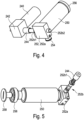
- the motor 240 has a gear 242 and an internally threaded interface 244.
- the pressure tank 250 has a valve 252, which has a valve housing 252a and a valve pin 252b. Furthermore, the pressure tank 250 has a gas outlet 254, an end piece 256, in particular a welded-on end piece, and a self-sealing filling screw 258.
- the pressure tank 250 is filled with air, which is pressurized to 200 bar.
- the pressure tank 250 is approved for a maximum pressure of at least twice the pressure actually used. In this way, the safety of the device 1, in particular against undesired gas escape, can be further improved.
- the valve housing 252 is connected to the pressure tank 250 in a gas-conducting manner at one end and is connected to the floating body 310 in a gas-conducting manner at the other end via the gas outlet 254.
- the valve pin 252b has an external thread interface 252b1 and the lock 252b2.
- the motor 240 is connected to the transmission 242 in a force-transmitting or torque-transmitting manner.
- the transmission 242 is intended to redirect the direction of the torque generated by the motor 240 at an angle of substantially 90 °, and in particular to reduce the speed provided by the motor 240.
- the rotational movement modified in direction and/or speed is transmitted to the internal thread interface 244.
- the internal thread interface 244 is connected to the external thread interface of the valve pin 252b engaged.
- the valve pin 252b is mounted in the valve housing in such a way that only a translational movement of the valve pin 252b is permitted. In particular, the valve pin 252b is prevented from rotating about its longitudinal axis by a tongue and groove connection.
- the rotational movement of the motor 240 produces a rotational movement of the internally threaded interface 244, which is intended to translate the valve pin 252b along its longitudinal axis.
- valve pin 252b moves over the threaded teeth in the valve housing 252a that are in engagement with each other, similar to a commercial vice, where a rotation of a nut with its degrees of freedom restricted also induces a movement of the movable holding jaw.
- the valve pin 252b fulfills two tasks: on the one hand, its original task, namely closing or opening the valve 252 and, on the other hand, locking or releasing the common unit detachably connected to the carrier device 100.
- the locking device 252b of the valve pin 252 engages in a recess in the carrier device 100 and thus fixes the common unit, in particular in a form-fitting manner, on the carrier device 100.
- valve pin 252b closes the pressure container 250 and one end of the valve pin, which serves as a lock 252b2, is inserted into the recess in the carrier device 100, whereby the common unit 200, 300 is on the carrier device 100 is fixed.
- the motor 240 moves the valve pin 252b in the manner described above, as a result of which one end of the valve pin, which serves as a lock 252b2, is pulled out of the recess in the carrier device 100, whereby the common unit detaches from the carrier device 100.
- the valve pin 252b releases the gas-conducting connection between the pressure tank 250 and the floating body 310.
- the air in the pressure tank 250 expands into the floating body 310, in particular a balloon made of latex, which has a diameter of 5 to 15 cm and a signal color.
- the floating body fills and pulls the common unit, which is non-detachably connected to the floating body via the gas outlet, upwards to the water surface.
- the common unit in particular the ferroelectric oscillating body 320, begins to emit an audio signal with a frequency in the range from 2 kHz to 10 kHz and a volume of approximately 100 decibels .
- the display 210 shows information about the set limit values regarding maximum depth and maximum duration, as well as information about the state of charge of the battery 220 and the operational readiness of the device 1, in particular about direct or indirect information about the internal pressure in the pressure tank 250.
- the display 210 also serves to display further information, such as the account balance of a cashless payment system or the locker number or remaining bathing time.
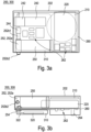
- FIG. 3a and 3b is a partially transparent schematic top view or a side view of the common unit consisting of monitoring device and reporting device Fig. 2 shown.
- circuit board 260 On the circuit board 260 are the display 210, the battery 220, the motor 240 with gear 242 internal thread interface 244, the pressure tank 250 with valve 252, having the valve housing 252a and the valve pin 252b, the gas outlet 254, various electrical and / or electronic components 262 , in particular a central processing unit (CPU), the pressure sensor device 264, the floating body 310, the ferroelectric oscillating body 320 and connecting lines 322 of the ferroelectric oscillating body 320 are arranged.
- CPU central processing unit
- a commercially available button cell is used as battery 220.
- the ferroelectric oscillating body 320 is electrically conductively connected to the signaling device 300 and/or the monitoring device 200 via the connecting lines 322.
- the ferroelectric oscillating body 320 is arranged within the floating body 310 in order to be able to use it as a sound body in the event of danger.
- the casting compound 202 extends around the common unit.
- the floating body 310 and the ferroelectric oscillating body 320 as well as the locking device 252b2 and at least part of a pressure sensor device 264, in particular the measuring sensor, are not enclosed by the casting compound 202.
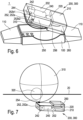
- Fig. 7 shows a partially transparent schematic three-dimensional view of the common unit 200, 300 consisting of monitoring device 200 and reporting device 300 of device 1 Fig. 1 , whereby the common unit 200, 300 with inflated floating body 310 is located on the water surface 20.
- the floating body 310 is dimensioned in such a way that it is able to transport the reporting device 300 and the monitoring device 200 to the water surface 20 and hold them there, in particular in such a way that a part of the floating body 310, in particular more than 50% of the Floating body 310, which is kept in a signal color, in particular red.
- the signaling device 300 begins via the ferroelectric oscillating body 320, which uses the floating body 310 as a resonance body and is supplied with energy by the battery 220, an acoustic signal with a frequency of 4 kHz and a volume of 100 decibels is emitted.
- This acoustic signal is supported by the floating body 310 on the water surface 20, which is kept in one or more signal colors, with regard to the location of the injured bather.
- Fig. 8 shows a modification of the first embodiment of the common unit described above, which is related to the embodiment of Figures 1, 2 , 4, 5 and 6 was explained. All of the above statements also apply in the same way to this modification of the first embodiment, unless otherwise follows from the following statements.
- the common unity of the Fig. 8 differs from the common unit described above Figures 1, 2 , 4, 5 and 6 that the pressure tank 250, the valve housing 252a and parts of the valve pin 252b are not enclosed by the casting compound 202.
- This has the advantage that in the event of an undesirable gas escape from the pressure tank 250, in particular in the form of a leak, the escaping gas does not flow into the casting compound 202 and damage it, but is released into the environment without further damage to the device 1.
- this design is advantageous because the pressure tank 250 is more easily accessible in the event of a scheduled or unscheduled overhaul.
- the common unit is preferably covered by a protective cover (not shown) in the event of no danger.
- the motor 240 can also be aligned with the valve pin 252b, so that a gear 242 can be dispensed with.
- a linear drive in particular a stepper motor, can also be provided, which is connected directly to the valve pin 252b in a force-transmitting manner in order to move it.
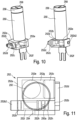
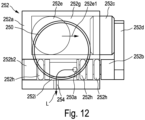
- Fig. 9 , 10 , 11 and 12 show partially transparent schematic three-dimensional views of a pressure tank 250 with a valve 252 according to a second embodiment of the present invention in a state before ( Fig. 9 and 11 ) or after ( Fig. 10 and 12 ) a triggering of a pyrotechnic device 252e from different perspectives. All of the above statements regarding the first embodiment also apply to the second embodiment in the same way, unless the following statements indicate otherwise.
- the second embodiment of the present invention differs from the first embodiment essentially in that the movement of the valve pin 252b is not caused by a motor 240, but by a pyrotechnic device 252e.
- the components motor 240, gearbox 242, internal thread interface 244 and the external thread interface 252b1 of the valve pin 252b are omitted.
- the pyrotechnic device 252e is arranged within the valve housing 252a in a first pressure channel 252g, wherein the valve housing 252a is preferably essentially gas-tight, in particular gas-tight, with respect to air with a pressure of up to 1,000 bar.
- the pyrotechnic device 252e is electrically conductively connected to the monitoring device 200, in particular to the battery 220, via a contacting device 252f.
- the pyrotechnic device 252e is further connected via the first pressure channel 252g in a gas-carrying manner to an actuator device 252c, in particular in the form of a Teflon-containing piston, such that the gas produced when the pyrotechnic device 252e is ignited exerts a force on the actuator device 252c in the direction of propagation 252e1 exercises, which is sufficient Actuator device 252c in at least one predetermined direction of movement, in particular a longitudinal axis of the actuator device 252c.
- the actuator device 252c is further connected to the valve pin 252b via a power transmission device 252d.
- the longitudinal axis of the valve pin 252b and the Teflon-containing piston 252c are aligned at least substantially parallel, in particular parallel, to one another.
- the force transmission device 252d is arranged outside the valve housing 252a and connects the valve pin 252b to the actuator device 252c in such a way that a movement of the actuator device 252c in the axial direction, in particular in the direction out of the valve housing 252a, is transmitted to the valve pin 252a, so that this moves at least substantially identically, in particular identically, with the actuator device 252c.
- the actuator device 252c is at least substantially completely, in particular completely, sunk into the valve housing 252a.
- the valve pin 252b closes the pressure vessel 250 in the initial situation (ie no danger is detected) and one end of the valve pin 252b, which serves as a lock 252b2, is inserted into the recess in the carrier device 100 (in Fig. 9 to 12 not shown), whereby the common unit 200, 300 is fixed to the carrier device 100.
- the valve pin 252b is displaced as described below, whereby one end of the valve pin 252b, which serves as a lock 252b2, is pulled out of the recess in the carrier device 100, whereby the common unit detaches from the carrier device 100.
- the valve pin 252b releases the gas-conducting connection between the pressure tank 250 and the floating body 310.
- energy is transferred from the battery 220 to the pyrotechnic device 252e by the monitoring device 200.
- This is preferably an energy pulse at a voltage of 12 volts.
- the pyrotechnic device 252e is ignited by the energy pulse, ie a component of the pyrotechnic device 252e and/or a substance of the pyrotechnic device 252e or within the pyrotechnic device 252e burns off. This creates a gas which collects in the valve housing 252a and thus builds up a pressure which acts against the actuator device 252c.
- the actuator device 252c is due to the Pressure building up within the valve housing 252a is at least partially pressed out of the valve housing 252a.
- the actuator device 252c is connected to the valve pin 252b via the force transmission device 252d in such a way that the movement of the actuator device 252c is transmitted to the valve pin 252a, whereby it is also displaced in the lateral direction along its longitudinal axis.
- one end of the valve pin 252b which serves as a lock 252b2 is pulled out of the recess in the carrier device 100, whereby the common unit detaches from the carrier device 100.
- the valve pin 252b releases the gas-conducting connection L between the pressure tank 250 via the outlet of the pressure tank 250a and the gas outlet 254 to the floating body 310.
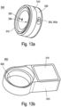
- FIG. 13a, 13b , 14, 15 and 16 a further embodiment of the device according to the invention is shown.
- This further embodiment differs from at least some of the previous ones in particular in that in the event of danger, not a common unit consisting of monitoring device 200 and reporting device 300 detaches from a carrier device 100, but rather that in case of danger, individual components of the monitoring device 200 remain in the carrier device 100, while others Components of the monitoring device 200 rise to the water surface 20 together with the reporting device 300. All of the above statements, in particular regarding the design and operation of the individual components, also apply to this further embodiment in the same way, unless otherwise emerges from the following statements and/or the relevant figures.
- the reporting device 300 together with the components of the monitoring device 200 described below, which rise to the water surface 20 together with the reporting device 300 in the event of danger, forms an alarm body 500.
- the carrier device 100 together with the components of the monitoring device 200 described below, which remain in the carrier device 100 in the event of danger, forms a basic device 600.
- Fig. 13a shows a schematic view of the alarm body 500, but without the floating body 310 (not shown).
- the alarm body 500 has: the pressure tank 250, the valve 252, in particular having the pyrotechnic device 252e, the floating body 310, a floating body holder 312 for attaching the Floating body 310, the ferroelectric oscillating body 320 and alarm body electronics 510.
- the alarm body electronics 510 has: a part of a plug-socket system (not shown) for electrically connecting the alarm body 500 to the base device 600, which is the complementary part of the plug-socket system. System (not shown).
- the alarm body electronics 510 has an independent energy supply in the form of the battery 220, in particular in the form of a button cell.
- the alarm body 500 can, according to a preferred embodiment, further have optoelectric components (not shown), in particular light-emitting diodes, in order to visually detect the effect of the audio signal generated by the ferroelectric oscillating body in the event of danger, in particular in the form of a light signal, in particular a flashing signal, preferably in the form of a flash-light-like signal generated at intervals.
- optoelectric components not shown, in particular light-emitting diodes, in order to visually detect the effect of the audio signal generated by the ferroelectric oscillating body in the event of danger, in particular in the form of a light signal, in particular a flashing signal, preferably in the form of a flash-light-like signal generated at intervals.
- the valve 252 is in the design of Fig. 13a integrated into the pressure tank 250 for the purpose of optimized space utilization.
- the operation of the valve 252 corresponds to the above statements regarding the other embodiments. Even if in the Fig. 13a the preferred variant of the pyrotechnic valve actuation is shown, it is of course possible to also implement the motor-driven valve actuation explained above in the alarm body 500.
- the gas released in the event of danger by the valve 252 flows through the gas outlet 254 (not shown), which is arranged, for example, near the inner edge of the floating body holder 312, into the floating body 310 and inflates it.
- the ferroelectric oscillating body 320 is in the design of Fig. 13a arranged behind the opening designated by the arrow 320, in particular on a circuit board of the alarm body electronics 510.
- the alarm body electronics 510 is intended, in particular designed, to open the valve 252 in response to a signal from the base device 600, so that the floating body 310 unfolds and the alarm body 500 detaches from the base device 600, as described in detail below, and rises to the water surface 20 and there by means of an audio signal, in particular the effect of which is supported by an optical signal, to draw attention to the dangerous situation.
- the energy for actuating the valve 252, in particular for igniting the pyrotechnic device 252e, can come from the battery 220 of the alarm body, or be provided by an energy storage device (not shown) of the base device 600, as described in detail below.
- the alarm body 500 is in the manner described above for the other embodiments via the lock 252b2 (in Fig. 13a not shown) fixed to the base device 600 by means of a recess (not shown) (see Fig. Fig. 14 ).
- the valve pin 252b is displaced in the manner described above, whereby one end of the valve pin, which serves as a lock 252b2, is pulled out of the recess in the base device 600, whereby the alarm body 500 detaches from the base device 600.
- the basic device 600 is in Fig. 13b shown.
- the base device 600 is intended to be worn, comparable to a watch, via a bracelet (not shown) on the arm, in particular on the wrist, of a person to be monitored.
- a bracelet not shown
- the base device 600 has a power supply that is independent of the alarm body 500, in particular a battery, preferably a rechargeable accumulator (not shown). Furthermore, the base device 600 has a wired, in particular wired, and/or wireless, in particular radio-based, such as WLAN, Bluetooth, etc., and/or light-based, in particular an infrared-based, interface for communication with an external data processing device, such as For example, a PC, a smartphone or the like. Data can be read out of the device via this interface and/or it can be configured in the manner described above, in particular using a device-specific program installed on the data processing device.
- the base device 600 also has the display 210 and base device electronics 610.
- the basic device electronics 610 has at least the following components described above, which are designed and act in a comparable manner here: the processor device, which is intended to fulfill at least part of the tasks of the processor device described above in the context of the other embodiments, if these cannot be taken over by the alarm body electronics 510; and the sensor device 264, in particular the pressure sensor device.
- the evaluation of the at least one sensor device 264 is carried out by the processor device of the base device 600. If this comes to the conclusion that there is a danger, it sends a signal to the alarm body 500, whereupon it detaches from the base device 600 in the manner described above.
- the base device 600 also has an alarm body receptacle 620, which is intended to accommodate the alarm body 500 at least partially in itself or according to an embodiment not shown in the event of no danger.
- the base device 600 is connected to the alarm body 500 in an electrically conductive manner.
- the alarm body electronics 510 can be supplied via the energy supply of the base device 600 in the event of no danger in order to protect the battery 220, which in this embodiment is at least essentially non-rechargeable.
- the charge level of the battery 220 of the alarm body 500 can also be monitored and communicated, for example, via the display 210.
- the energy supply of the base device 600 can be used to maintain the voltage of the battery 220, in particular to charge it when necessary.
- the Figures 15 and 16 show the alarm body 500 in the event of danger, with the alarm body 500 in the Fig. 15 is still in the ascent phase to the water surface 20, while he is in the Fig. 16 has already arrived at the water surface 20.
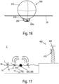
- Fig. 17 shows a schematic representation of a system according to an embodiment of the present invention and an exemplary application in a swimming pool.
- Each person 10 to be monitored wears a device 1 on his wrist.
- At least one base station 400 which has a receiving device 410 and a transmitting device 420, is arranged in relation to the swimming pool in such a way that the Receiving device 410 is able to receive a signal from the device 1, in particular the reporting device 300.
- the reporting device 300 of the device 1 of the person 10 located on the pool floor sends out an audio signal so that the other bathing people 10 or people in the pool area (not shown) are made aware of the danger.
- the base station 400 detects the audio signal using its receiving device 410 and, using its transmitting device 420, also sends an emergency call to more distant locations, such as rescue stations and/or water stations and/or fire departments and/or police stations and/or medical emergency services.
- the transmitting device 420 can generate a further audio signal and/or visual signal, which also alerts people who are further away, for example at the edge of the pool, to the danger.
- Fig. 18 shows a schematic representation of a method for monitoring people in water according to an embodiment of the present invention, comprising the steps, in particular in the following order: S1 Attaching to a person a device for monitoring people in water of the type described above in various embodiments; S2 Detecting via the sensor device whether, in particular how deep, the person is in the water; S3 Detecting, via a time measuring device of the monitoring device, how long the person stays in the water, in particular below a predetermined depth; S4 Detecting a hazard as soon as the person stays in the water for longer than a predetermined period of time, in particular below a predetermined depth, in particular continuously; S5 at least partially, in particular completely, releasing the reporting device from the carrier device in response to a signal from the monitoring device; S6 The signaling device rises to the surface of the water.
- the method further comprises the step: S7 Emitting an audio signal and/or a visual signal and/or a radio signal through the reporting device.
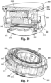
- FIG. 19 to 23 A further embodiment of a device according to the invention for monitoring people in the water 1 is shown, which has the alarm body 500 and the base device 600.
- the alarm body 500 is connected to the base device 600, in particular inserted into the alarm body receptacle 620 of the base device 600, with the floating body 310 not being shown.
- the alarm body 500 the Figures 19 and 20 has the pressure tank 250, which is formed by a recess within the alarm body 500 and in particular is further limited by a cover of the alarm body 500.
- the valve pin 252b in Fig. 19 has released a gas passage between pressure tank 250 and floating body 310, while this gas passage is in Fig. 20 is blocked by the valve pin 252b.
- the movement of the valve pin from the closed position ( Fig. 20 ) to the open position ( Fig. 19 ) is preferably designed to be reversible in a non-destructive manner.
- the movement of the valve pin 252b is caused by a pyrotechnic device 252e, which is ignited in the event of danger in response to a signal from the alarm body electronics 510.
- the gas released by ignition creates a force on the valve pin 252b, moving it from the closed position to the open position.
- Ignition is carried out by a signal from the alarm body electronics 510, which in the inserted state are connected to each other in a signal and/or energy-conducting manner with the basic device electronics 610 via electrical contacts 550, 650.
- the electrical contacts 550, 650 are preferably designed so that they are separated from one another in the event of danger, in particular if the alarm body 500 detaches from the base device 600.
- the sensor device 264 in particular in the form of a pressure sensor device, is arranged in the base device 600. Either the measurement data is transmitted to the alarm body 500 and the depth and time are monitored via the alarm body electronics 510 and in the event of danger, a control signal is transmitted to the alarm body electronics 510, which in turn causes the pyrotechnic device 252e to be ignited.
- the alarm body 500 is supplied with energy, particularly in the event of danger after separation from the base device 600, via its own battery 540.
- the base device 600 is supplied with energy, particularly in the event of danger after the alarm body 500 has been separated, via its own battery 640.
- the alarm body 500 is designed to separate from the base device 600 in the event of danger by using an increasing volume of the floating body 310 during the transfer of the floating body 310 into the buoyant state during inflation, a force against a part of the base device 600, in particular a base plate, the force causing a separation of the alarm body 500 from the base device 600.
- the floating body 310 is held on the alarm body 500 by a floating body holder 312.
- the ferroelectric oscillating body 320 is connected to an interior of the floating body 310 in a gas-carrying manner. In this way, the sound generated by the ferromagnetic oscillating body 320 is emitted via the floating body 310 at least partially above the water surface.
- the alarm body 500 When inserted, the alarm body 500 is sealed from the base device 600 by means of a sealing device 520, in particular a sealing ring.
- a sealing device 520 in particular a sealing ring.
- individual components or assemblies of the base device 600 can be sealed against one another via a sealing device 630, in particular a sealing ring.
- the base device 600 has a, in particular slot-like, passage which fluidly connects the sensor device 264 with the environment, in particular the water surrounding the device 1.
- the sensor device 264 is at least essentially protected from unwanted physical influences, such as dirt and/or shocks, while the detection of the parameter to be detected, in particular the ambient pressure as a measure of the water depth, is made possible.
- the device 1 can be connected, at least temporarily, to an external control device (not shown), such as a personal computer, via a multi-pole, in particular 4-pole, contact.
- an external control device such as a personal computer
- limit values for depth and/or maximum time duration below the depth limit can be adjusted according to the level of the person to be monitored and/or data, in particular depth/time profiles, can be read out or the like.
- a connecting line 700 with a connecting device 710 is held on the base device 600 by means of a, in particular magnetic, locking device 662 during the connection to the external control device.
- the base device 600 also has a localization device 330 in the form of an LED, in particular a high-performance LED, which preferably emits a flashing light signal in the event of danger.
- a localization device 330 in the form of an LED, in particular a high-performance LED, which preferably emits a flashing light signal in the event of danger.
Description
Die vorliegende Erfindung betrifft eine Vorrichtung und ein Verfahren zum Schutz vor Badeunfällen, insbesondere zum frühzeitigen Erkennen von Ertrinkenden, und dergleichen.The present invention relates to a device and a method for protecting against swimming accidents, in particular for early detection of drowning people, and the like.
Nach Schätzungen der Organisation blausand.de (siehe dazu auch wikipedia.org) kommen in Europa jährlich über 20.000 Menschen bei Badeunfällen ums Leben. Jedoch liegt die Anzahl der Beinahe-Ertrinkungsunfälle im Schnitt fünfmal höher als die Anzahl der tödlichen Ertrinkungsunfälle, wobei viele dieser Beinahe-Ertrinkungsunfälle schwerwiegende und teils irreparable gesundheitliche Schäden zur Folge haben.According to estimates by the organization blausand.de (see also wikipedia.org), over 20,000 people die in swimming accidents in Europe every year. However, the number of near-drowning accidents is on average five times higher than the number of fatal drowning accidents, with many of these near-drowning accidents resulting in serious and sometimes irreparable health damage.
Schwere Badeunfälle werden häufig dadurch eingeleitet, dass ein Badender bzw. Schwimmer im Wasser das Bewusstsein verliert - wofür viele Gründe in Frage kommen können - und dies von Dritten nicht bemerkt wird. Denn entgegen einer verbreiteten Annahme hat nämlich z.B. ein Schwimmer, dessen Kräfte erschöpft sind und der deshalb zu ertrinken droht, meist nicht mehr die Kraft, durch Zeichen oder Rufen auf sich aufmerksam zu machen. Dies führt dazu, dass er unbeobachtet unter die Wasseroberfläche sinkt. Gelingt es in einer solchen Situation, den Betroffenen in den nächsten zwei bis drei Minuten nach dem Bewusstseinsverlust zu retten, bleiben zumeist keine Unfallfolgen zurück. Erfolgt die Rettung zwischen drei und fünf Minuten nach dem Bewusstseinsverlust, besteht noch eine hohe Chance das Leben des Betroffenen zu retten. Dauert die Rettung länger, sinken die Chancen des Betroffenen zu überleben zunehmend.Serious swimming accidents are often caused by a bather or swimmer losing consciousness in the water - for which there can be many reasons - and this is not noticed by third parties. Contrary to popular belief, a swimmer, for example, whose strength has been exhausted and who is therefore in danger of drowning, usually no longer has the strength to draw attention to himself by signaling or shouting. This causes it to sink below the surface of the water unobserved. In such a situation, if the person affected can be saved within the next two to three minutes after losing consciousness, there are usually no consequences of the accident. If rescue occurs between three and five minutes after loss of consciousness, there is still a high chance of saving the life of the person affected. If the rescue takes longer, the affected person's chances of survival decrease increasingly.
Aus der
In stark frequentierten Bereichen, wie z.B. in Schwimmbädern, wird das sichere Erkennen von Gefahrensignalen mittels Empfängern ferner aufgrund von Störsignalen aus unterschiedlichsten Quellen erschwert.In heavily frequented areas, such as swimming pools, the reliable detection of danger signals using receivers is also made more difficult due to interference signals from a wide variety of sources.
Aus der
Die
Die Empfangseinrichtung ist hierbei entweder fest in einem Schwimmbad installiert, was die Nutzbarkeit dieses Systems auf Schwimmbäder beschränkt, welche diese Empfangseinrichtung installiert haben. Alternativ kann auch eine mobile Empfangseinheit, z.B. von Eltern, für die Zeit des Besuchs im Bad mitgenommen und im Gewässer platziert werden, während die zu überwachenden Personen, z.B. Kinder, die mit der Kontrolleinheit ausgestattet sind, baden.The receiving device is either permanently installed in a swimming pool, which limits the usability of this system to swimming pools that have this receiving device installed. Alternatively, a mobile reception unit can be taken by parents, for example, for the duration of the visit to the pool and placed in the water while the people to be monitored, for example children who are equipped with the control unit, bathe.
Es ist eine Aufgabe der vorliegenden Erfindung, eine leistungsfähige Vorrichtung zur Überwachung von Personen im Wasser bereitzustellen, welche insbesondere flexibel und/oder zuverlässig einsetzbar ist, um Badende, insbesondere Kinder, vor Schäden zu bewahren.It is an object of the present invention to provide a powerful device for monitoring people in the water, which can be used in particular flexibly and/or reliably in order to protect bathers, especially children, from harm.
Diese Aufgabe wird erfindungsgemäß durch die in Anspruch 1 beschriebene Vorrichtung gelöst. Eine erfindungsgemäße Anlage ist Gegenstand des Anspruchs 10. Ein erfindungsgemäßes Verfahren zur Überwachung von Personen im Wasser ist Gegenstand des Anspruchs 12. Vorteilhafte Weiterbildungen sind Gegenstand der Unteransprüche. Nach einem Aspekt der vorliegenden Erfindung weist eine Vorrichtung zur Überwachung von Personen im Wasser, auf: eine Trägereinrichtung, welche dafür vorgesehen ist an einer Person befestigt zu werden, eine Überwachungseinrichtung, welche von der Trägereinrichtung aufgenommen ist, aufweisend eine Sensoreinrichtung und eine Prozessoreinrichtung, wobei die Sensoreinrichtung mit der Prozessoreinrichtung verbunden ist, und eine Meldeeinrichtung, welche von der Trägereinrichtung aufgenommen ist und welche mit der Überwachungseinrichtung verbunden ist. Die Vorrichtung zur Überwachung von Personen im Wasser weist ferner einen Aktuator auf. Die Sensoreinrichtung ist dazu eingerichtet, zu erfassen, wie lange sich die Person im Wasser unterhalb einer vorher festgelegten Tiefe aufhält, wobei die Prozessoreinrichtung dazu eingerichtet ist, basierend auf dieser Erfassung und wenn die Person sich länger als eine vorher festgelegte Zeitspanne im Wasser unterhalb der vorher festgelegten Tiefe aufhält ein Signal zu erzeugen und wobei die Meldeeinrichtung einen Schwimmkörper aufweist und wobei die Meldeeinrichtung dazu eingerichtet ist, sich auf das Signal der Prozessoreinrichtung hin von der Trägereinrichtung zumindest teilweise, insbesondere vollständig, zu lösen und an die Wasseroberfläche aufzusteigen. Der Aktuator ist mit dem Schwimmkörper verbunden und dafür vorgesehen, auf das Signal der Prozessoreinrichtung hin den Schwimmkörper von einem ersten Zustand, in welchem der Schwimmkörper nicht schwimmfähig ist, in einen zweiten Zustand, in welchem der Schwimmkörper schwimmfähig ist, zu überführen.This object is achieved according to the invention by the device described in
Unter einer "Vorrichtung zur Überwachung von Personen im Wasser", im Folgenden kurz "Vorrichtung", im Sinne der vorliegenden Erfindung wird ein System verstanden, welches an einer zu überwachenden Person befestigt ist und welches dafür vorgesehen ist, einen oder mehrere Parameter zu überwachen, aus welchem bzw. welchen die Vorrichtung Rückschlüsse daraus ziehen kann, ob ein Gefahrensfall für die Person, an welcher die Vorrichtung befestigt ist, vorliegt, und im Gefahrensfall ein Signal abgibt, welches dafür geeignet ist, andere Personen, insbesondere in der direkten Umgebung, auf den Gefahrensfall aufmerksam zu machen, sodass diese in der Lage sind der gefährdeten Person zu helfen.A “device for monitoring people in water”, hereinafter referred to as “device”, in the sense of the present invention is understood to mean a system which is attached to a person to be monitored and which is intended to monitor one or more parameters, from which or which the device can draw conclusions as to whether there is a danger for the person to whom the device is attached and, in the event of danger, emits a signal which is suitable for alerting other people, especially in the immediate vicinity the To alert people to danger so that they are able to help the person at risk.
Unter einer "Trägereinrichtung" im Sinne der vorliegenden Erfindung wird jede Form von Einrichtung verstanden, welche geeignet ist, an einer zu überwachenden Person, insbesondere an einem Kind, insbesondere an einem Arm und/oder einem Bein und/oder dem Hals und/oder an einem Teil der Badebekleidung befestigt zu werden, und welche eingerichtet ist, die für die Vorrichtung im Folgenden darüber hinaus als wesentlich beschriebenen Einrichtungen, wie zum Beispiel die Überwachungseinrichtung und die Meldeeinrichtung, in sich, insbesondere lösbar, aufzunehmen und/oder an sich, insbesondere lösbar, zu befestigen.A “carrier device” in the sense of the present invention is understood to mean any form of device which is suitable for being attached to a person to be monitored, in particular to a child, in particular to an arm and/or a leg and/or the neck and/or to be attached to a part of the swimwear, and which is set up to accommodate the devices described below as essential for the device, such as the monitoring device and the reporting device, in itself, in particular releasably, and / or per se, in particular releasably , to fix.
Unter einer "Überwachungseinrichtung" im Sinne der vorliegenden Erfindung ist eine Einrichtung zu verstehen, welche dafür vorgesehen ist, über einen oder mehrere Sensoren einen Zustand der zu überwachenden Person, insbesondere deren Aufenthalt im Wasser an sich und/oder deren Tiefe im Wasser und/oder einer Zeitdauer, zu bestimmen, diesen Zustand mit vorher festgelegten Grenzwerten abzugleichen und im Falle des Überschreitens bzw. Unterschreitens des Grenzwertes bzw. der Grenzwerte einen Alarm zu veranlassen, welcher aber nicht von der Überwachungseinrichtung selbst sondern von der Meldeeinrichtung abgegeben wird.A “monitoring device” in the context of the present invention is to be understood as meaning a device which is intended to monitor, via one or more sensors, a condition of the person to be monitored, in particular their stay in the water itself and/or their depth in the water and/or a period of time, to compare this state with previously set limit values and, if the limit value or values are exceeded or fallen below, to trigger an alarm, which is not issued by the monitoring device itself but by the reporting device.
Unter einer "Sensoreinrichtung" im Sinne der vorliegenden Erfindung ist eine Einrichtung zu verstehen, welche zumindest aus einem, insbesondere gemäß der DIN 1319-1 definierten, (Messgrößen-)Aufnehmer besteht, der auf eine Messgröße unmittelbar anspricht. Des Weiteren kann die "Sensoreinrichtung" im Sinne der vorliegenden Erfindung u.a. weitere Elemente der Messkette umfassen, wie zum Beispiel Verstärker, Analog/Digital-Wandler, Codierer und dergleichen.A “sensor device” in the sense of the present invention is to be understood as meaning a device which consists of at least one (measured variable) sensor, in particular defined in accordance with DIN 1319-1, which responds directly to a measured variable. Furthermore, the “sensor device” in the sense of the present invention can include, among other things, other elements of the measurement chain, such as amplifiers, analog/digital converters, encoders and the like.
Unter einer "Prozessoreinrichtung" im Sinne der vorliegenden Erfindung ist eine Einrichtung zu verstehen, welche dafür vorgesehen ist Signale, insbesondere elektrische Signale, aufzunehmen, zu verarbeiten und Signale, insbesondere elektrische Signale, abzugeben. Bevorzugt ist eine Prozessoreinrichtung im Sinne der vorliegenden Erfindung ein elektronischer Schaltkreis mit einer zentralen Recheneinheit (CPU), weiter bevorzugt ist die Prozessoreinrichtung, zumindest teilweise, in einem integrierten Schaltkreis (IC) realisiert.A “processor device” in the context of the present invention is to be understood as a device which is intended to receive and process signals, in particular electrical signals, and to output signals, in particular electrical signals. For the purposes of the present invention, a processor device is preferably an electronic circuit with a central processing unit (CPU); more preferably, the processor device is, at least partially, implemented in an integrated circuit (IC).
Unter einer "Meldeeinrichtung" im Sinne der vorliegenden Erfindung ist eine Einrichtung zu verstehen, welche dafür vorgesehen ist, im Gefahrensfall auf die zu überwachende Person hinzuweisen. Dies kann beispielsweise allein über den an der Wasseroberfläche schwimmenden, insbesondere in Signalfarben gestalteten, Schwimmkörper erfolgen. Des Weiteren kann dieser Hinweis, insbesondere zusätzlich, durch akustische und/oder optische, z.B. Blitzlicht, Signale erfolgen.A “reporting device” in the sense of the present invention is to be understood as a device which is intended to alert the person to be monitored in the event of danger to point out. This can be done, for example, solely via the floating body floating on the water surface, in particular designed in signal colors. Furthermore, this notice can, in particular additionally, be provided by acoustic and/or optical signals, for example flash lights.
Alle möglichen Formen des Verbs "aufweisen" sind im Sinne der vorliegenden Erfindung so zu verstehen, dass es sich hierbei jeweils um nicht-abschließende Aufzählungen handelt.For the purposes of the present invention, all possible forms of the verb “have” are to be understood as meaning that they are non-exhaustive lists.
Die im Rahmen der vorliegenden Erfindung beschriebenen Einrichtungen wie Trägereinrichtung, Sensoreinrichtung, Überwachungseinrichtung etc. sind nicht zwingend als bauliche Einheiten sondern lediglich als Funktionseinheiten zu verstehen.The devices described in the context of the present invention, such as carrier devices, sensor devices, monitoring devices, etc., are not necessarily to be understood as structural units but merely as functional units.
Die erfindungsgemäße Vorrichtung ist insbesondere vorteilhaft, da somit erstmals eine Vorrichtung bereitgestellt wird, welche unabhängig von den örtlichen Gegebenheiten in jeder Art von Gewässer, z.B. Pool, Freibad, Schwimmbad, See, Fluss oder Meer, eingesetzt werden kann. Eine zusätzliche Infrastruktur, wie zum Beispiel eine Energieversorgung und/oder eine Basisstation, ist am Badeort nicht erforderlich. Dies schließt jedoch explizit nicht aus, dass die erfindungsgemäße Vorrichtung in eine entsprechende Anlage mit Basisstation integriert ist, um ein, insbesondere zusätzlich, von der Meldeeinrichtung abgegebenes Signal zu empfangen und dieses und/oder ein anderes Signal auszusenden, welches einen erweiterten Personenkreis auf die Gefahrensituation aufmerksam machen kann, insbesondere Aufsichtspersonen, welche eine entsprechende Empfangseinrichtung bei sich bzw. an sich tragen.The device according to the invention is particularly advantageous because, for the first time, a device is provided which can be used in any type of body of water, e.g. pool, outdoor swimming pool, lake, river or sea, regardless of the local conditions. Additional infrastructure, such as a power supply and/or a base station, is not required at the seaside resort. However, this does not explicitly rule out that the device according to the invention is integrated into a corresponding system with a base station in order to receive a, in particular additional, signal emitted by the reporting device and to send out this and/or another signal which alerts an expanded group of people to the dangerous situation can draw attention, especially to supervisors who carry an appropriate reception device with them.
Die erfindungsgemäße Vorrichtung ist weiterhin insbesondere vorteilhaft, da nicht die gesamte Vorrichtung im Gefahrensfall an die Wasseroberfläche aufsteigen muss, sondern lediglich diejenigen Komponenten, welche für das Anzeigen des Gefahrensfalls erforderlich sind, insbesondere die Meldeeinheit.The device according to the invention is furthermore particularly advantageous since not the entire device has to rise to the water surface in the event of danger, but only those components which are required to indicate the danger, in particular the signaling unit.
Die Vorrichtung kann einfach, insbesondere lösbar, insbesondere mittels eines für (Klein-)Kinder nicht lösbaren Sicherheitsverschlusses, an der zu überwachenden Person befestigt werden.The device can be easily, in particular releasably, attached to the person to be monitored, in particular by means of a safety lock that cannot be detached by (small) children.
Des Weiteren weist die Vorrichtung auch nicht nur ausgewählte Personen, wie zum Beispiel Bademeister oder Eltern, auf den Gefahrensfall hin, sondern alle in Sicht- und/oder Hörweite befindlichen Personen, was die Reaktionszeit deutlich verkürzen kann.Furthermore, the device not only alerts selected people, such as lifeguards or parents, to the danger, but also all people within sight and/or hearing distance, which can significantly shorten the reaction time.
Beim Einsatz der erfindungsgemäßen Vorrichtung tragen zu überwachende Personen, wie beispielsweise Kleinkinder, ein Exemplar der Vorrichtung am Handgelenk, welches insbesondere nicht größer ist als eine Armbanduhr. Bei der Verwendung der Vorrichtung in öffentlichen Bädern ist dieses bevorzugt in dem dort üblicherweise verwendeten Schlüsselarmband für einen Bekleidungsschrank integriert.When using the device according to the invention, people to be monitored, such as small children, wear a copy of the device on their wrist, which is in particular no larger than a wristwatch. When using the device in public bathrooms, it is preferably integrated into the key bracelet for a clothing cabinet that is usually used there.
Nach einer Ausführung der Vorrichtung erfasst die Überwachungseinrichtung als relevanten Parameter den an der Sensoreinrichtung herrschenden Druck, insbesondere Wasserdruck, in Abhängigkeit von dessen zeitlichem Verlauf. Vorzugsweise erfasst die Sensoreinrichtung auch auf den Träger bezogene Parameter wie zum Beispiel Bewegungen der Vorrichtung.According to one embodiment of the device, the monitoring device records the pressure prevailing at the sensor device, in particular water pressure, as a relevant parameter, depending on its course over time. Preferably, the sensor device also detects parameters related to the wearer, such as movements of the device.
Nach einer Ausführung weist die Vorrichtung ferner Zusatzeinrichtungen auf, wie eine Anzeige des aktuellen Batteriezustands und/oder der Einsatzbereitschaft der Vorrichtung oder solche, die zumindest nicht vorwiegend für Sicherheitszwecke dienen. Dies können beispielsweise elektronische Schlüsselsysteme oder bargeldlose Bezahlsysteme sein, wofür bevorzugt ein RFID-Transponder oder dergleichen in die Vorrichtung integriert sein kann. Zur Anzeige von gespeicherten Informationen welche beispielsweise das Überwachungssystem oder die Bezahlfunktion betreffen, oder des Batteriestands ist vorzugsweise ein Anzeige-Display in die Vorrichtung integriert.According to one embodiment, the device further has additional devices, such as a display of the current battery status and/or the operational readiness of the device or those that are at least not primarily used for security purposes. These can be, for example, electronic key systems or cashless payment systems, for which an RFID transponder or the like can preferably be integrated into the device. To display stored information relating, for example, to the monitoring system or the payment function, or the battery level, a display is preferably integrated into the device.
Nach einer Ausführung ist die Vorrichtung dafür vorgesehen, das Vorliegen einer Alarmsituation abhängig von den individuellen Eigenschaften des Trägers bei jeweils unterschiedlichen äußeren Bedingungen festzustellen. Hierbei kann es sich beispielsweise um Vorrichtungen handeln, welche für Kleinkinder, Nichtschwimmer, Schwimmer oder Sportschwimmer konfiguriert sind. Die Überwachungseinrichtung der Vorrichtung schließt dabei abhängig von einer bestimmten Verweildauer der Vorrichtung unterhalb einer vorbestimmten Wassertiefe auf das Vorliegen eines Gefahrensfalls. Erfasst die Sensoreinrichtung der Vorrichtung auch deren Bewegung, so kann eine längere Bewegungslosigkeit ebenfalls, nach einem nicht beanspruchten Ausführungsbeispiel, ein Kriterium für das Vorliegen eines Gefahrensfalls sein. Beispielsweise kann bei einem Schwimmer, welcher die Vorrichtung am Handgelenk trägt, ein Überdruck von mindestens 0,1 bar über eine Dauer länger als 45 Sekunden einen Gefahrensfall definieren. Ein Überdruck von 0,1 bar herrscht in einem Meter Wassertiefe. Das Erreichen einer Wassertiefe von einem oder mehr als einem Meter mit der Vorrichtung am Handgelenk ist im Normalfall nur möglich, wenn sich der Kopf eines Schwimmers weitgehend unter der Wasseroberfläche befindet. Daher ist es im Rahmen üblicher Badesituationen so gut wie ausgeschlossen, dass die Vorrichtung über einen längeren Zeitraum einem Überdruck von 0,1 bar ausgesetzt ist. Da ein solcher Überdruck auch kurzzeitig durch die Schwimmbewegung des Badenden verursacht werden kann oder auch bei einem beabsichtigten Untertauchen erreicht wird, wird erst dann ein Gefahrensfall angenommen, wenn dieser Überdruck über einen vorbestimmten längeren Zeitraum besteht, welcher aber noch keine Gefährdung des Badenden birgt, um das Zeitfenster für eine Rettung nicht unnötig zu verkleinern. Dieser Zeitraum sowie der relevante Überdruck werden bevorzugt entsprechend individueller Eigenschaften der zu überwachenden Person festgelegt.According to one embodiment, the device is intended to determine the existence of an alarm situation depending on the individual characteristics of the wearer under different external conditions. These can, for example, be devices that are configured for small children, non-swimmers, swimmers or competitive swimmers. The monitoring device of the device infers the existence of an emergency depending on a specific dwell time of the device below a predetermined water depth. If the sensor device of the device also detects its movement, a prolonged period of immobility can also, according to an unclaimed exemplary embodiment, be a criterion for the existence of a hazard. For example, for a swimmer who wears the device on his wrist, an excess pressure of at least 0.1 bar for a period longer than 45 seconds can define a hazard. There is an excess pressure of 0.1 bar at a depth of one meter. Reaching a water depth of one or more than one meter with the device on the wrist is normally only possible if a swimmer's head is largely below the surface of the water. Therefore, it is more common in the framework In bathing situations it is virtually impossible for the device to be exposed to an overpressure of 0.1 bar over a longer period of time. Since such an overpressure can also be caused for a short time by the bather's swimming movement or can also be achieved when the bather intends to submerge, a danger case is only assumed if this overpressure exists for a predetermined longer period of time, but which does not pose any danger to the bather not to unnecessarily reduce the time window for a rescue. This period and the relevant overpressure are preferably determined according to the individual characteristics of the person to be monitored.
Vorzugsweise ist es möglich, die einen Gefahrensfall definierenden Parameter und deren Werte abhängig von den körperlichen Eigenschaften oder Fähigkeiten einer Person für die Vorrichtung festzulegen. Vorzugsweise ist die Vorrichtung so gestaltet, dass die Werte der einen Gefahrensfall definierenden Parameter zum Beispiel auch und/oder nur von Aufsichtspersonen, insbesondere Eltern von (kleinen) Kindern, festgelegt werden können. Eine entsprechende Konfiguration kann entweder an der Vorrichtung selbst über Bedienelemente vorgenommen werden oder mittels einer zu verbindenden Konfigurationseinheit, wie zum Beispiel einem Computer.Preferably, it is possible to determine the parameters defining a hazard and their values for the device depending on the physical characteristics or abilities of a person. Preferably, the device is designed in such a way that the values of the parameters defining a hazard can, for example, also and/or only be set by supervisors, in particular parents of (small) children. A corresponding configuration can be carried out either on the device itself using operating elements or by means of a configuration unit to be connected, such as a computer.
Nach einer Ausführung ist der Schwimmkörper ein Ballon, welcher dafür vorgesehen ist mit einem Gas gefüllt zu werden. Bevorzugt weist der Ballon ein Elastomer oder mehrere Elastomere, insbesondere eine Polymerdispersion und besonders bevorzugt ein Latex-Material auf. Bevorzugt weist das für den Ballon verwendete Material bzw. weisen die für den Ballon verwendeten Materialien eine Beständigkeit, insbesondere eine Unempfindlichkeit gegenüber Chlorwasser und/oder Salzwasser auf. Nach einer Ausführung weisen alle Elemente der Vorrichtung zur Überwachung von Personen eine Beständigkeit, insbesondere eine Unempfindlichkeit gegenüber Chlorwasser und/oder Salzwasser auf.According to one embodiment, the floating body is a balloon which is intended to be filled with a gas. The balloon preferably has one or more elastomers, in particular a polymer dispersion and particularly preferably a latex material. The material or materials used for the balloon preferably have resistance, in particular insensitivity to chlorine water and/or salt water. According to one embodiment, all elements of the device for monitoring people have resistance, in particular insensitivity to chlorine water and/or salt water.
Als Gase kommen alle Gase infrage, welche geeignet sind, den Schwimmkörper und gegebenenfalls daran befestigte, insbesondere nicht-lösbar befestigte, Einrichtungen an die Wasseroberfläche aufsteigen zu lassen.Suitable gases are all gases which are suitable for allowing the floating body and any devices attached to it, in particular non-removably attached, to rise to the water surface.
Dies ist insbesondere vorteilhaft, da der Ballon im gefüllten Zustand ein sehr gutes Verhältnis von Eigengewicht zu Verdrängung im Wasser aufweist, wodurch die Auftriebskraft erhöht wird. Alternativ kann dieses gute Verhältnis von Eigengewicht zu Verdrängung im Wasser dazu genutzt werden, die Baugröße des Ballons zu reduzieren, was wiederum eine verkleinerte Bauform der Vorrichtung begünstigen kann.This is particularly advantageous because the balloon, when filled, has a very good ratio of its own weight to displacement in the water, which increases the buoyancy force. Alternatively, this good ratio of dead weight to Displacement in the water can be used to reduce the size of the balloon, which in turn can promote a smaller design of the device.
Wie bereits erwähnt, weist die Vorrichtung einen Aktuator auf, welcher mit dem Schwimmkörper verbunden ist und welcher dafür vorgesehen ist, auf das Signal der Prozessoreinrichtung hin den Schwimmkörper von einem ersten Zustand, in welchem der Schwimmkörper nicht schwimmfähig ist, in einen zweiten Zustand, in welchem der Schwimmkörper schwimmfähig ist, zu überführen.As already mentioned, the device has an actuator which is connected to the floating body and which is intended to move the floating body from a first state, in which the floating body is not buoyant, into a second state, in response to the signal from the processor device which the floating body is buoyant.
Unter einem "Aktuator" im Sinne der vorliegenden Erfindung ist eine Einrichtung zu verstehen, welche dafür vorgesehen ist, durch einen aktiven Vorgang den Schwimmkörper von dem ersten Zustand in den zweiten Zustand zu überführen, insbesondere durch Freigabe einer gasführenden Verbindung zum Schwimmkörper hin, z.B. in Form eines gesteuerten oder geregelten Ventils oder in Form einer Vorrichtung zur Durchbrechung einer Versiegelung. Dies ist insbesondere vorteilhaft, da somit der Schwimmkörper nicht die ganze Zeit in der Lage sein muss, an die Wasseroberfläche aufzusteigen, sondern erst im Gefahrensfall. Liegt der Schwimmkörper beispielsweise in Form eines Ballons vor, so liegt dieser ursprünglich im nicht-aufgeblasenen Zustand vor und wird erst im Gefahrensfall mit Gas gefüllt.An “actuator” in the sense of the present invention is to be understood as a device which is intended to transfer the floating body from the first state to the second state through an active process, in particular by releasing a gas-carrying connection to the floating body, e.g In the form of a controlled or regulated valve or in the form of a device for breaking a seal. This is particularly advantageous because the floating body does not have to be able to rise to the surface of the water all the time, but only in the event of danger. If the floating body is in the form of a balloon, for example, it is originally in the non-inflated state and is only filled with gas in the event of danger.
Dies gestattet eine reduzierte Bauform, welche es erstmals ermöglicht, eine Vorrichtung der oben beschriebenen Art, insbesondere zur Befestigung am Arm, insbesondere in einer Größe etwa vergleichbar mit einer Armbanduhr, bereitzustellen.This allows a reduced design, which makes it possible for the first time to provide a device of the type described above, in particular for attachment to the arm, in particular in a size approximately comparable to a wristwatch.
Nach einer Ausführung weist die Vorrichtung weiterhin einen Drucktank auf und der Aktuator
- (a) eine pyrotechnische Einrichtung auf, welche dafür vorgesehen ist, auf ein Signal der Prozessoreinrichtung hin eine gasleitende Verbindung zwischen dem Drucktank und dem Schwimmkörper freizugeben; und/oder
- (b) eine Antriebseinrichtung, insbesondere einen Motor, auf, welche dafür vorgesehen ist, auf ein Signal der Prozessoreinrichtung hin eine gasleitende Verbindung zwischen dem Drucktank und dem Schwimmkörper freizugeben.
- (a) a pyrotechnic device which is intended to release a gas-conducting connection between the pressure tank and the floating body in response to a signal from the processor device; and or
- (b) a drive device, in particular a motor, which is intended to release a gas-conducting connection between the pressure tank and the floating body in response to a signal from the processor device.
Unter einer "pyrotechnischen Einrichtung" im Sinne der vorliegenden Erfindung ist eine Einrichtung zu verstehen, welche eingerichtet ist, auf ein Signal der Überwachungseinrichtung hin elektrisch und/oder optisch und/oder chemisch gezündet zu werden. Nach dem Zünden verbrennt die pyrotechnische Substanz zumindest teilweise unter Freisetzung eines Gases.A “pyrotechnic device” in the sense of the present invention is to be understood as meaning a device which is set up to be ignited electrically and/or optically and/or chemically in response to a signal from the monitoring device become. After ignition, the pyrotechnic substance burns at least partially, releasing a gas.
Die pyrotechnische Einrichtung ist nach einer Ausführung ein Behälter mit einer pyrotechnischen Substanz, welcher dafür vorgesehen ist, nach dem Zünden der pyrotechnischen Substanz das entstehende Gas dazu zu verwenden, eine gasführende Verbindung, insbesondere von dem Drucktank, zu dem Schwimmkörper freizugeben, sodass ein Gas, welches zumindest nicht ausschließlich das mittels der pyrotechnischen Einrichtung erzeugte Gas ist, wenigstens teilweise, insbesondere vollständig, in den Schwimmkörper geleitet wird.According to one embodiment, the pyrotechnic device is a container with a pyrotechnic substance, which is intended to use the resulting gas after the pyrotechnic substance has been ignited to release a gas-carrying connection, in particular from the pressure tank, to the floating body, so that a gas, which is at least not exclusively the gas generated by the pyrotechnic device, is at least partially, in particular completely, guided into the floating body.
Bevorzugt weist die pyrotechnische Komponente eine Mini-Sprengkapsel und/oder eine pyrotechnische Mini-Kapsel auf. Nach einer Ausführung wird die pyrotechnische Komponente elektrisch gezündet, insbesondere bei einer Spannung von mehr als 5 V, bevorzugt, insbesondere wenigstens ungefähr, 12 V.The pyrotechnic component preferably has a mini detonator and/or a pyrotechnic mini capsule. According to one embodiment, the pyrotechnic component is ignited electrically, in particular at a voltage of more than 5 V, preferably, in particular at least approximately, 12 V.
Die Ausprägungsform (a) ist insbesondere vorteilhaft, da somit ein vergleichsweise einfacher Aufbau des Aktuators erreicht wird, welcher eine sehr schnelle Reaktionszeit aufweist.Embodiment (a) is particularly advantageous because a comparatively simple structure of the actuator is achieved, which has a very fast response time.
Nach einer Ausführung wird die pyrotechnische Einrichtung elektrisch gezündet, insbesondere bei einer Spannung von 12 V. Nach einer Ausführung weist die Batterie der Vorrichtung zur Überwachung von Personen eine Batterie, insbesondere eine Knopfzelle, mit einer Betriebsspannung von 3 V auf. Die Anmelder haben herausgefunden, dass einer solchen Batterie auch kurzfristig Leistung mit einer höheren Spannung, insbesondere 12 V, entnommen werden kann, um die pyrotechnische Einrichtung zu zünden.According to one embodiment, the pyrotechnic device is ignited electrically, in particular at a voltage of 12 V. According to one embodiment, the battery of the device for monitoring people has a battery, in particular a button cell, with an operating voltage of 3 V. The applicants have discovered that power at a higher voltage, in particular 12 V, can also be drawn from such a battery for a short time in order to ignite the pyrotechnic device.
Dies ist insbesondere vorteilhaft, da somit für den normalen Betrieb eine kleinbauende Knopfzelle verwendet werden kann, welche jedoch im Alarmfall in der Lage ist, die pyrotechnische Einrichtung zu zünden.This is particularly advantageous since a small button cell can be used for normal operation, but is able to ignite the pyrotechnic device in the event of an alarm.
Die Ausprägungsform (b) ist insbesondere vorteilhaft, da hier nur eine einzige Energiequelle, insbesondere im Form einer Batterie, insbesondere einer Knopfzelle, benötigt wird, welche besonders bevorzugt ohne besondere Hilfsmittel und ohne besondere Kenntnisse und insbesondere ohne Gefährdung der Funktionssicherheit der Vorrichtung getauscht werden kann. Des Weiteren ist diese Ausprägungsform insbesondere vorteilhaft, da insbesondere der Motor im Wesentlichen alterungsbeständig ist und somit eine Revision desselben, bevorzugt für die gesamte Lebensdauer der Vorrichtung, nicht erforderlich ist.Embodiment (b) is particularly advantageous since only a single energy source is required here, in particular in the form of a battery, in particular a button cell, which can particularly preferably be replaced without special aids and without special knowledge and in particular without endangering the functional reliability of the device . Furthermore, this embodiment is particularly advantageous because the motor in particular is essentially resistant to aging and therefore a revision of the same, preferably for the entire service life of the device, is not necessary.
Nach einer Ausführung weist die Vorrichtung weiterhin eine Gaszuführeinrichtung auf, aufweisend:
- (a) einen Drucktank, welcher dafür vorgesehen ist, ein mit Druck beaufschlagtes Gas in sich aufzunehmen und auf ein Signal der Prozessoreinrichtung hin an den Schwimmkörper abzugeben; und/oder
- (b) einen Behälter, welcher dafür vorgesehen ist, ein Flüssiggas in sich aufzunehmen, welches auf ein Signal der Prozessoreinrichtung hin zumindest teilweise, insbesondere vollständig, in den gasförmigen Zustand übergeht und an den Schwimmkörper abgegeben wird; und/oder
- (c) eine pyrotechnische Komponente, welche dafür vorgesehen ist, auf ein Signal der Prozessoreinrichtung hin abzubrennen und das dabei entstehende Gas an den Schwimmkörper abzugeben; und/oder
- (d) eine pulver- und/oder festkörperförmige erste Substanz aufweist, welche dafür vorgesehen ist, auf ein Signal der Prozessoreinrichtung hin mit einer zweiten Substanz in Kontakt zu kommen, wobei ein Gas entsteht, welches an den Schwimmkörper abgegeben wird.
- (a) a pressure tank, which is intended to contain a pressurized gas and to release it to the floating body in response to a signal from the processor device; and or
- (b) a container which is intended to contain a liquid gas which, in response to a signal from the processor device, changes at least partially, in particular completely, into the gaseous state and is released to the floating body; and or
- (c) a pyrotechnic component which is intended to burn in response to a signal from the processor device and to release the resulting gas to the floating body; and or
- (d) has a powder and/or solid-form first substance which is intended to come into contact with a second substance in response to a signal from the processor device, thereby producing a gas which is released to the floating body.
Unter einer "Gaszuführeinrichtung" im Sinne der vorliegenden Erfindung ist eine Einrichtung zu verstehen, welche wenigstens ein Element zur Gasbereitstellung und/oder zur Gasbevorratung und/oder zum Gastransport aufweist.A “gas supply device” in the sense of the present invention is to be understood as meaning a device which has at least one element for gas provision and/or for gas storage and/or for gas transport.
Die Ausprägungsform (a) ist insbesondere vorteilhaft, da zur Abgabe des Gases an den Schwimmkörper keine weitere Vorrichtung erforderlich ist, da sich das mit Druck beaufschlagte Gas aufgrund des Prinzips von Le Chatelier aus eigenem Antrieb heraus in den Schwimmkörper hinein ausdehnt, bis ein gleichmäßiger Druck im Gesamtsystem vorliegt.The embodiment (a) is particularly advantageous since no further device is required to deliver the gas to the floating body, since the pressurized gas expands of its own accord into the floating body due to Le Chatelier's principle until a uniform pressure present in the overall system.
Als Gas kommt nach dieser Ausprägungsform insbesondere (Umgebungs-)Luft infrage, da diese faktisch unbegrenzt zur Verfügung steht und bei der Fertigung der Vorrichtung lediglich komprimiert werden muss. Des Weiteren können auch Edelgase, insbesondere Helium, Neon, Argon, Krypton, Xenon und/oder Mischungen derselben verwendet werden.According to this embodiment, (ambient) air is particularly suitable as a gas, since this is actually available in unlimited quantities and during the manufacture of the device just needs to be compressed. Furthermore, noble gases, in particular helium, neon, argon, krypton, xenon and/or mixtures thereof, can also be used.
Nach einer Ausführung nimmt der Drucktank das Gas mit einem Druck von wenigstens 10 bar, insbesondere wenigstens 50 bar, insbesondere wenigstens 100 bar, insbesondere wenigstens 200 bar, insbesondere wenigstens 400 bar auf.According to one embodiment, the pressure tank receives the gas at a pressure of at least 10 bar, in particular at least 50 bar, in particular at least 100 bar, in particular at least 200 bar, in particular at least 400 bar.
Dies ist insbesondere vorteilhaft, da je höher der Druck des Gases innerhalb der Druckeinrichtung ist, desto kleiner kann die Druckeinrichtung aufgrund des Boyle-Mariotte'schen Gesetzes bauen, um dasselbe Volumen des Schwimmkörpers zu füllen.This is particularly advantageous since the higher the pressure of the gas within the pressure device, the smaller the pressure device can be built due to Boyle-Mariotte's law in order to fill the same volume of the floating body.
Nach einer Ausführung ist der Drucktank dafür vorgesehen, in vordefinierten zeitlichen Abständen oder kontinuierlich den Druck in dem Drucktank zu erfassen und an die Überwachungseinrichtung weiterzugeben.According to one embodiment, the pressure tank is intended to record the pressure in the pressure tank at predefined time intervals or continuously and to pass it on to the monitoring device.
Dies ist insbesondere vorteilhaft, da somit die Einsatzbereitschaft der Vorrichtung regelmäßig automatisch von der Vorrichtung selbst überwacht wird. Ein Revisionszyklus, d.h. eine Inspektion der Vorrichtung, insbesondere von geschultem Personal, kann somit deutlich verlängert werden. Bevorzugt kann auf eine Revision während der Lebensdauer der Vorrichtung vollständig verzichtet werden.This is particularly advantageous since the operational readiness of the device is regularly and automatically monitored by the device itself. A revision cycle, i.e. an inspection of the device, especially by trained personnel, can thus be significantly extended. Preferably, an overhaul can be completely dispensed with during the service life of the device.
Unter einem "Flüssiggas" im Sinne der vorliegenden Erfindung ist ein Gas zu verstehen, welches bei Raumtemperatur unter vergleichsweise geringem Druck, von bis zu maximal 100 bar flüssig bleibt. Ein Flüssiggas im Sinne der vorliegenden Erfindung ist insbesondere ein Gas, welches Ethan und/oder Propan und/oder Butan oder eine beliebige Mischung von wenigstens zwei derselben aufweist, insbesondere aus Ethan und/oder Propan und/oder Butan oder einer Mischung von wenigstens zwei derselben besteht.For the purposes of the present invention, a “liquid gas” is to be understood as meaning a gas which remains liquid at room temperature under a comparatively low pressure of up to a maximum of 100 bar. A liquid gas in the context of the present invention is in particular a gas which contains ethane and/or propane and/or butane or any mixture of at least two of them, in particular of ethane and/or propane and/or butane or a mixture of at least two of them consists.
Die Ausprägungsform (b) ist insbesondere vorteilhaft, da somit eine noch höhere Dichte des Füllmediums vor der Füllung des Schwimmkörpers erreicht werden kann. So kann beispielsweise eine Menge von 1 cm3 an Flüssiggas geeignet sein, im gasförmigen Zustand ein Volumen von 250 cm3 des Schwimmkörpers auszufüllen. Des Weiteren muss der Behälter nur für vergleichsweise geringe Drücke von bis zu 200 bar (inkl. Sicherheitsreserve) eingerichtet sein.The embodiment (b) is particularly advantageous since an even higher density of the filling medium can be achieved before the floating body is filled. For example, an amount of 1 cm 3 of liquid gas can be suitable for filling a volume of 250 cm 3 of the floating body in the gaseous state. Furthermore, the container only needs to be set up for comparatively low pressures of up to 200 bar (including safety reserve).
Unter einer "pyrotechnischen Komponente" im Sinne der vorliegenden Erfindung ist eine pyrotechnische Substanz zu verstehen, welche eingerichtet ist auf ein Signal der Überwachungseinrichtung hin elektrisch und/oder optisch und/oder chemisch gezündet zu werden. Nach dem Zünden verbrennt die pyrotechnische Substanz zumindest teilweise unter Freisetzung eines Gases.A “pyrotechnic component” in the sense of the present invention is to be understood as meaning a pyrotechnic substance which is set up to be ignited electrically and/or optically and/or chemically in response to a signal from the monitoring device. After ignition, the pyrotechnic substance burns at least partially, releasing a gas.
Die pyrotechnische Substanz ist nach einer Ausführung in einem Behälter angeordnet, welcher dergestalt gasdicht mit dem Schwimmkörper, insbesondere über den Gasauslass, verbunden ist, dass das während bzw. nach der Zündung der Substanz entstehende Gas wenigstens teilweise, insbesondere vollständig, in den Schwimmkörper geleitet wird.According to one embodiment, the pyrotechnic substance is arranged in a container which is connected in a gas-tight manner to the floating body, in particular via the gas outlet, in such a way that the gas produced during or after the ignition of the substance is at least partially, in particular completely, guided into the floating body .
Bevorzugt weist die pyrotechnische Komponente eine Mini-Sprengkapsel und/oder eine pyrotechnische Mini-Kapsel auf. Nach einer Ausführung wird die pyrotechnische Komponente elektrisch gezündet, insbesondere bei einer Spannung von mehr als 5 V, bevorzugt, insbesondere wenigstens ungefähr, 12 V.The pyrotechnic component preferably has a mini detonator and/or a pyrotechnic mini capsule. According to one embodiment, the pyrotechnic component is ignited electrically, in particular at a voltage of more than 5 V, preferably, in particular at least approximately, 12 V.
Die Ausprägungsform (c) ist insbesondere vorteilhaft, da somit die Gefahr eines Druckverlustes des Druckbehälters ausgeschlossen werden kann, was einen Revisionszyklus, d.h. eine Inspektion der Vorrichtung, insbesondere von geschultem Personal, deutlich verlängern kann. Bevorzugt kann auf eine Revision während der Lebensdauer der Vorrichtung vollständig verzichtet werden.The embodiment (c) is particularly advantageous since the risk of a pressure loss in the pressure vessel can be excluded, which can significantly extend a revision cycle, i.e. an inspection of the device, in particular by trained personnel. Preferably, an overhaul can be completely dispensed with during the service life of the device.
Nach einer Ausführung wird die pyrotechnische Komponente elektrisch gezündet, insbesondere bei einer Spannung von 12 V. Nach einer Ausführung ist die Batterie der Vorrichtung zur Überwachung von Personen eine Batterie, insbesondere eine Knopfzelle, mit einer Betriebsspannung von 3 V. Die Anmelder haben herausgefunden, dass einer solchen Batterie auch kurzfristig Leistung mit einer höheren Spannung, insbesondere 12 V, entnommen werden kann, um die pyrotechnische Komponente zu zünden.According to one embodiment, the pyrotechnic component is ignited electrically, in particular at a voltage of 12 V. According to one embodiment, the battery of the device for monitoring people is a battery, in particular a button cell, with an operating voltage of 3 V. The applicants have found that Power with a higher voltage, in particular 12 V, can also be drawn from such a battery for a short time in order to ignite the pyrotechnic component.
Dies ist insbesondere vorteilhaft, da somit für den normalen Betrieb eine kleinbauende Knopfzelle verwendet werden kann, welche jedoch im Alarmfall in der Lage ist, die pyrotechnische Komponente zu zünden.This is particularly advantageous because a small button cell can be used for normal operation, but is capable of igniting the pyrotechnic component in the event of an alarm.
Die pulver- und/oder festkörperförmige erste Substanz weist bevorzugt Natriumtartrat, ein Natriumsalz der Weinsäure mit der Summenformel C4H4O6Na2, wie es unter anderem in gebundener Form in vielen Früchten vorkommt, auf. Die zweite Substanz ist bevorzugt eine flüssige Substanz, insbesondere eine Wasser-aufweisende Substanz, insbesondere wenigstens im Wesentlichen Wasser, insbesondere Wasser. Wasser umfasst in diesem Kontext sowohl Süß- als auch Salzwasser, wie es in zum Baden geeigneten natürlichen Landstrichen oder vom Menschen geschaffenen Einrichtungen vorkommt.The powder and/or solid first substance preferably has sodium tartrate, a sodium salt of tartaric acid with the molecular formula C 4 H 4 O 6 Na 2 , as it occurs, among other things, in bound form in many fruits. The second substance is preferably a liquid substance, in particular a water-containing substance, in particular at least essentially water, especially water. Water in this context includes both fresh and salt water, as found in natural areas suitable for swimming or in man-made facilities.
Beim Kontakt der beiden Substanzen beginnt eine chemische Reaktion, bei welcher mindestens eine gasförmige Komponente entsteht.When the two substances come into contact, a chemical reaction begins, in which at least one gaseous component is formed.
Die Ausprägung (d) ist insbesondere vorteilhaft, da ihr Aufbau sehr einfach ist und die in der Vorrichtung enthaltene pulver- und/oder festkörperförmige erste Substanz nicht brennbar ist und/oder, insbesondere für Kinder, gesundheitlich unbedenklich ist.Expression (d) is particularly advantageous because its structure is very simple and the powder and/or solid-form first substance contained in the device is not flammable and/or is harmless to health, especially for children.
Nach einer Ausführung ist die Meldeeinrichtung dafür vorgesehen, ein Audio-Signal und/oder ein visuelles Signal und/oder ein Funksignal auszusenden, sobald sich die Meldeeinrichtung von der Trägereinrichtung zumindest teilweise, insbesondere vollständig, losgelöst an der Wasseroberfläche befindet.According to one embodiment, the reporting device is intended to send out an audio signal and/or a visual signal and/or a radio signal as soon as the reporting device is at least partially, in particular completely, detached from the carrier device on the water surface.
Dies ist insbesondere vorteilhaft, da somit der Effekt des im Gefahrensfall an der Wasseroberfläche schwimmenden Schwimmkörpers weiter verstärkt wird und die Aufmerksamkeit anderer Personen in der Umgebung der gefährdeten Person aktiv auf die Gefahrensituation gelenkt wird.This is particularly advantageous because the effect of the floating body floating on the surface of the water in the event of danger is further increased and the attention of other people in the area around the person at risk is actively drawn to the dangerous situation.
Nach einer Ausführung ist ein visuelles Signal ein Leuchtsignal, insbesondere ein blinkendes Signal, insbesondere ein intervallweise erzeugtes Blitzlicht-artiges Signal.According to one embodiment, a visual signal is a light signal, in particular a flashing signal, in particular a flash-light-like signal generated at intervals.
Nach einer Ausführung ist die Meldeeinrichtung dafür vorgesehen, ein für das menschliche Ohr hörbares Audio-Signal, insbesondere mit einer Lautstärke von wenigstens 80 Dezibel, bevorzugt von wenigstens 90 Dezibel und weiter bevorzugt von wenigstens 100 Dezibel, abzugeben.According to one embodiment, the reporting device is intended to emit an audio signal that is audible to the human ear, in particular with a volume of at least 80 decibels, preferably at least 90 decibels and more preferably at least 100 decibels.
In einer bevorzugten Ausführungsform weist das Audio-Signal eine Frequenz im Bereich von 50 Hz bis 10 kHz auf. Als besonders geeignet hat sich dabei hinsichtlich der Reichweite und des Energieverbrauchs ein Frequenzbereich von 2 kHz bis 10 kHz und insbesondere von 3 kHz bis 5 kHz gezeigt.In a preferred embodiment, the audio signal has a frequency in the range from 50 Hz to 10 kHz. A frequency range from 2 kHz to 10 kHz and in particular from 3 kHz to 5 kHz has proven to be particularly suitable in terms of range and energy consumption.
Dies ist insbesondere vorteilhaft, da ein Audio-Signal unabhängig von der Blickrichtung von Personen in der Umgebung der gefährdeten Person wahrgenommen wird. Somit ist eine unmittelbare Aufmerksamkeitsfokussierung der Personen in der Umgebung der gefährdeten Person wenigstens begünstigt, insbesondere gewährleistet.This is particularly advantageous because an audio signal is perceived regardless of the direction of view of people in the area around the person at risk. So there is one Immediate focus of attention of those around the person at risk is at least favored, and in particular guaranteed.
Nach einer Ausführung weist die Meldeeinrichtung einen Schwingkörper, insbesondere einen ferroelektrischen Schwingkörper, insbesondere in Form eines Piezo-Elements, auf, welcher ein für den Menschen wahrnehmbares Geräusch erzeugt.According to one embodiment, the signaling device has an oscillating body, in particular a ferroelectric oscillating body, in particular in the form of a piezo element, which generates a noise that is perceptible to humans.
Dies ist insbesondere vorteilhaft, da ein Schwingkörper in der Lage ist, einen entsprechenden Schalldruck zu erzeugen, welcher von Personen in der Umgebung der gefährdeten Person als Ton bzw. Geräusch wahrgenommen werden kann.This is particularly advantageous because a vibrating body is able to generate a corresponding sound pressure, which can be perceived as a tone or noise by people in the area around the person at risk.
Nach einer bevorzugten Ausführung ist der Schwingkörper am Schwimmkörper in einer Weise angebracht, dass der Schwimmkörper als Klangkörper fungiert, welcher den Effekt des Schwingkörpers modifiziert, insbesondere verstärkt.According to a preferred embodiment, the oscillating body is attached to the floating body in such a way that the floating body functions as a sound body, which modifies, in particular amplifies, the effect of the oscillating body.
Nach einer Ausführung weist die Vorrichtung weiterhin eine Schutzabdeckung auf, welche an der Trägereinrichtung angeordnet ist und welche wenigstens die Meldeeinrichtung, insbesondere wenigstens die Meldeeinrichtung und die Überwachungseinrichtung, insbesondere wasserdurchlässig, bedeckt, wobei die Schutzabdeckung dafür vorgesehen ist, sich auf ein Signal der Überwachungseinrichtung hin von der Trägereinrichtung wenigstens teilweise, insbesondere vollständig, zu lösen, sodass wenigstens die Meldeeinrichtung nach dem wenigstens teilweisen Lösen offenliegt.According to one embodiment, the device further has a protective cover which is arranged on the carrier device and which covers at least the reporting device, in particular at least the reporting device and the monitoring device, in particular water-permeable, the protective cover being intended to respond to a signal from the monitoring device to be detached from the carrier device at least partially, in particular completely, so that at least the reporting device is exposed after the at least partial detachment.
Dies ist insbesondere vorteilhaft, da somit die empfindlichen Komponenten der Vorrichtung, insbesondere die Überwachungseinrichtung und die Meldeeinrichtung, und ganz besonders der mitunter empfindliche Schwimmkörper während des Einsatzes - abgesehen vom Gefahrensfall - stets vor Krafteinwirkungen und/oder Sonneneinstrahlung geschützt ist.This is particularly advantageous because the sensitive components of the device, in particular the monitoring device and the signaling device, and especially the sometimes sensitive floating body, are always protected from forces and/or sunlight during use - apart from in the event of danger.
Im Gefahrensfall legt die Schutzabdeckung wenigstens die Meldeeinrichtung frei, sodass diese sich im Anschluss von der Trägereinrichtung lösen und an die Wasseroberfläche aufsteigen kann.In the event of danger, the protective cover at least exposes the signaling device so that it can then detach from the carrier device and rise to the surface of the water.
Die Wasserdurchlässigkeit ermöglicht es, die Sensoreinrichtung, insbesondere eine Drucksensoreinrichtung, welche dafür vorgesehen ist, den umgebenden Wasserdruck als ein Maß für die Tiefe der zu überwachenden Person im Wasser zu bestimmen, in einer Weise unterhalb der Schutzabdeckung anzuordnen, dass auch die Sensoreinrichtung von der Schutzabdeckung mit geschützt wird und trotzdem weiterhin in der Lage ist, einen aussagekräftigen Messwert zu bestimmen.The water permeability makes it possible to arrange the sensor device, in particular a pressure sensor device, which is intended to determine the surrounding water pressure as a measure of the depth of the person to be monitored in the water, below the protective cover in such a way that the sensor device is also protected from is protected by the protective cover and is still able to determine a meaningful measured value.
Nach einer Ausführung weist die Vorrichtung einen weiteren Aktuator auf, welcher dafür vorgesehen ist, auf ein Signal der Überwachungseinrichtung hin die Schutzabdeckung wenigstens teilweise, insbesondere vollständig, freizulegen und/oder wenigstens teilweise, insbesondere vollständig, von der Trägereinrichtung zu lösen.According to one embodiment, the device has a further actuator, which is intended to at least partially, in particular completely, expose the protective cover and/or at least partially, in particular completely, release it from the carrier device in response to a signal from the monitoring device.
Dies ist insbesondere vorteilhaft, da somit die Schutzabdeckung in einer Weise gestaltet werden kann, dass sie im Nicht-Gefahrensfall fest mit der Trägereinrichtung verbunden ist und die Gefahr eines versehentlichen Ablösens wenigstens verringert, insbesondere ausgeschlossen, ist.This is particularly advantageous since the protective cover can thus be designed in such a way that it is firmly connected to the carrier device in the event of no danger and the risk of accidental detachment is at least reduced, in particular eliminated.
Nach einer Ausführung wird die Schutzabdeckung durch den Schwimmkörper von der Trägereinrichtung wenigstens teilweise, insbesondere vollständig, gelöst, insbesondere im Zuge des Aufblasens des Ballons.According to one embodiment, the protective cover is at least partially, in particular completely, detached from the carrier device by the floating body, in particular in the course of inflating the balloon.
Nach einer Ausführung werden der Aktuator und der weitere Aktuator von einer gemeinsamen Aktuatoreinrichtung gebildet.According to one embodiment, the actuator and the further actuator are formed by a common actuator device.
Dies ist insbesondere vorteilhaft, da somit auf zusätzliche Komponenten, welche Bauraum benötigen und Kosten verursachen sowie zusätzliches Fehlerpotential einbringen, verzichtet werden kann. Insbesondere weist der Aktuator eine bewegliche Komponente auf, welche im Nicht-Gefahrensfall zum einen die Schutzabdeckung arretiert und zum anderen den Druckbehälter verschließt und im Gefahrensfall verschoben wird, wodurch die Schutzabdeckung wenigstens teilweise gelöst wird und der Druckbehälter zum Schwimmkörper hin geöffnet wird.This is particularly advantageous because it means that additional components, which require installation space and cause costs and introduce additional error potential, can be dispensed with. In particular, the actuator has a movable component, which on the one hand locks the protective cover in the event of no danger and, on the other hand, closes the pressure vessel and is moved in the event of danger, whereby the protective cover is at least partially released and the pressure vessel is opened towards the floating body.
Nach der Erfindung ist die Sensoreinrichtung eine Sensoreinrichtung, insbesondere eine Drucksensoreinrichtung, welche dafür vorgesehen ist, ein Signal bereitzustellen, aus welchem die Überwachungseinrichtung direkt erschließen oder indirekt berechnen kann, ob, und wie tief, sich die Person im Wasser befindet.According to the invention, the sensor device is a sensor device, in particular a pressure sensor device, which is intended to provide a signal from which the monitoring device can directly determine or indirectly calculate whether, and how deep, the person is in the water.
Dies ist vorteilhaft, da über die Tiefe, in welcher sich die Sensoreinrichtung im Wasser befindet, darauf geschlossen werden kann, ob sich der Kopf der zu überwachenden Person noch oberhalb der Wasseroberfläche befindet oder nicht.This is advantageous because the depth at which the sensor device is located in the water can be used to determine whether the head of the person to be monitored is still above the water surface or not.
Ein bevorzugtes Maß zur Bestimmung der Tiefe ist der Wasserdruck, da dieser um je 1 bar je 10 Meter Wassertiefe gegenüber dem sich unmittelbar oberhalb der Wasseroberfläche befindlichen Luftdrucks zunimmt.A preferred measure for determining depth is the water pressure, as this increases by 1 bar for every 10 meters of water depth compared to the air pressure immediately above the water surface.
Nach einer Ausführung erfasst die Sensoreinrichtung der Vorrichtung zusätzlich den Luftdruck unmittelbar, d.h. im Bereich von bis zu 2 Meter, oberhalb der Wasseroberfläche und die Überwachungseinrichtung bestimmt die Differenz vom Luftdruck unmittelbar oberhalb der Wasseroberfläche zum Umgebungsdruck der Vorrichtung im Wasser, um eine genauere Abschätzung der Tiefe, in welcher sich die Sensoreinrichtung im Wasser befindet, zu ermöglichen.According to one embodiment, the sensor device of the device additionally detects the air pressure directly, i.e. in the range of up to 2 meters, above the water surface and the monitoring device determines the difference between the air pressure immediately above the water surface and the ambient pressure of the device in the water in order to provide a more precise estimate of the depth , in which the sensor device is located in the water.
Nach einer Ausführung weist die Überwachungseinrichtung eine Zeitmesseinrichtung auf, wobei die Überwachungseinrichtung dafür vorgesehen ist, auf ein, insbesondere vordefiniertes, Signal der Sensoreinrichtung hin eine Zeiterfassung zu starten.According to one embodiment, the monitoring device has a time measuring device, the monitoring device being intended to start a time recording in response to a, in particular predefined, signal from the sensor device.
Das vordefinierte Signal der Sensoreinrichtung ist ein Messwert, welcher sich über- bzw. unterhalb eines vordefinierten Schwellwertes, d.h. im Gefahrenbereich, befindet.The predefined signal from the sensor device is a measured value which is above or below a predefined threshold value, i.e. in the danger zone.
Dies ist vorteilhaft, da somit lediglich die spezifische Zeitspanne erfasst wird, in welcher sich die Sensoreinrichtung und damit verbunden die Vorrichtung und damit verbunden die zu überwachende Person in einem Gefahrenbereich, nämlich unterhalb einer vorgegebenen Maximaltiefe im Wasser, befindet. In anderen Betriebszuständen der Vorrichtung wird die Zeitmessung deaktiviert, was zu einer Energieeinsparung und damit verbunden zu einer Verlängerung der Lebensdauer, insbesondere der Batterielebensdauer, führt.This is advantageous because only the specific period of time is recorded in which the sensor device and, associated with it, the device and, associated with it, the person to be monitored are in a danger area, namely below a predetermined maximum depth in the water. In other operating states of the device, the time measurement is deactivated, which leads to energy savings and, associated with this, to an extension of the service life, in particular the battery life.
Die Tiefe allein ist, zumindest bei erfahrenen Schwimmern, bis zu einem gewissen Grad kein ausschließlicher Indikator für einen Gefahrensfall. Hält sich die zu überwachende Person allerdings zu lange unterhalb der vorgegebenen Maximaltiefe auf, so kann auf einen Gefahrensfall geschlossen werden.To a certain extent, depth alone is not an exclusive indicator of danger, at least for experienced swimmers. However, if the person being monitored stays below the specified maximum depth for too long, it can be concluded that there is a danger.
Die Übewachungseinrichtung überträgt das Signal an die Meldeeinrichtung, welches veranlasst, dass sich die Meldeeinrichtung von der Trägereinrichtung wenigstens teilweise, insbesondere vollständig löst, und an die Wasseroberfläche aufsteigt, wenn eine im Zuge der Zeiterfassung erfasste Zeitdauer eine vorgegebene Zeitdauer überschritten hat.The monitoring device transmits the signal to the reporting device, which causes the reporting device to detach from the carrier device at least partially, in particular completely, and rise to the water surface when a period of time recorded in the course of time recording has exceeded a predetermined period of time.
Dies ist vorteilhaft, da somit ein Alarm nur im Gefahrensfall, d.h. wenn sich die zu überwachende Person länger als eine vorgegebene Maximaldauer kontinuierlich unterhalb einer vorgegebenen Maximaltiefe unter Wasser befindet, ausgelöst wird.This is advantageous because an alarm is only triggered in the event of danger, i.e. if the person to be monitored is continuously under water below a predetermined maximum depth for longer than a predetermined maximum duration.
Wird die vorgegebene Maximaltiefe wieder unterschritten, d.h. befindet sich die zu überwachende Person wieder in einer zulässigen Tiefe bevor die Maximaldauer überschritten wurde, so wird die Zeiterfassung ohne Auslösen eines Alarms abgebrochen.If the specified maximum depth is not reached again, i.e. the person to be monitored is again at a permissible depth before the maximum duration has been exceeded, the time recording is canceled without triggering an alarm.
Nach einer Ausführung weist die Meldeeinrichtung weiterhin ein schnurartiges Element auf, welches die Meldeeinrichtung und die Trägereinrichtung miteinander verbindet, auch wenn sich die Meldeeinrichtung im Wesentlichen losgelöst von der Trägereinrichtung an der Wasseroberfläche befindet.According to one embodiment, the reporting device further has a cord-like element which connects the reporting device and the carrier device to one another, even if the reporting device is located on the water surface, essentially detached from the carrier device.
Dies ist insbesondere vorteilhaft, da somit, insbesondere in trüben Gewässern wie z.B.This is particularly advantageous because, especially in cloudy waters such as e.g.
Flüssen oder Seen, die zu überwachende Person im Gefahrensfall schneller aufgefunden werden kann, auch wenn aufgrund der Wassertrübung und/oder der Tiefe der zu überwachenden Person im Wasser ein direktes Erkennen der zu überwachenden Person von der Wasseroberfläche her nicht oder nicht ausreichend möglich ist.Rivers or lakes, the person to be monitored can be found more quickly in the event of danger, even if direct recognition of the person to be monitored from the water surface is not possible or not sufficiently possible due to the turbidity of the water and/or the depth of the person to be monitored in the water.
Nach einer Ausführung weist die Trägereinrichtung und/oder die Basiseinrichtung eine Lokalisierungseinrichtung auf. Diese ist insbesondere dafür vorgesehen, insbesondere eingerichtet, die zu überwachende Person im Gefahrensfall schneller aufzufinden, insbesondere wenn aufgrund der Wassertrübung und/oder der Tiefe der zu überwachenden Person im Wasser ein direktes Erkennen der zu überwachenden Person von der Wasseroberfläche her nicht oder nicht ausreichend möglich ist. Nach einer Weiterbildung weist die Lokalisierungseinrichtung eine Geräusch- und/oder Lichtquelle auf. Beispiele für Lichtquellen sind LEDs, insbesondere Hochleistungs-LEDs, welche insbesondere dafür eingerichtet sind, ein blinkendes Lichtsignal auszusenden.According to one embodiment, the carrier device and/or the base device has a localization device. This is intended, in particular, designed to locate the person to be monitored more quickly in the event of danger, especially if, due to the turbidity of the water and/or the depth of the person to be monitored in the water, direct recognition of the person to be monitored from the water surface is not possible or not sufficiently possible is. According to a further development, the localization device has a noise and/or light source. Examples of light sources are LEDs, in particular high-performance LEDs, which are particularly designed to emit a flashing light signal.
Nach einer Ausführung ist der Alarmkörper und/oder die Meldeeinrichtung dafür vorgesehen, insbesondere eingerichtet, sich von der Basiseinrichtung und/oder der Überwachungseinrichtung zu trennen, insbesondere indem während des Überführens des Schwimmkörpers in den schwimmfähigen Zustand, insbesondere während des Aufblasens, ein sich vergrößerndes Volumen des Schwimmkörpers genutzt wird, eine Kraft gegenüber einem Teil der Basiseinrichtung und/oder der Überwachungseinrichtung aufzubauen, welche dazu genutzt wird, eine Trennung von Alarmkörper und/oder Meldeeinrichtung von der Basiseinrichtung und/oder der Überwachungseinrichtung zu bewirken. Dies ist insbesondere vorteilhaft, da auf diese Weise auf zusätzliche Komponenten zur Lösung und/oder Trennung verzichtet werden kann, was den Aufbau der Vorrichtung vereinfacht.According to one embodiment, the alarm body and/or the signaling device is intended, in particular designed, to separate from the base device and/or the monitoring device, in particular by increasing the volume during the transfer of the floating body into the buoyant state, in particular during inflation of the floating body is used to build up a force against a part of the base device and / or the monitoring device, which is used to cause a separation of the alarm body and / or reporting device from the base device and / or the monitoring device. This is particularly advantageous since in this way additional components for solution and/or separation can be dispensed with, which simplifies the structure of the device.
Nach einer Ausführung ist der ferroelektrische Schwingkörper gasführend mit einem Innenraum des Schwimmkörpers verbunden. Dies ist insbesondere vorteilhaft, da auf diese Weise der durch den ferromagnetischen Schwingkörper erzeugte Schall über den Schwimmkörper zumindest teilweise oberhalb der Wasseroberfläche ausgesandt wird, sobald der Alarmkörper im Gefahrensfall an die Wasseroberfläche aufgestiegen ist. Insbesondere wird ein verlustbehafteter Schallübergang von Wasser zu Luft an der Wasseroberfläche vermieden.According to one embodiment, the ferroelectric oscillating body is connected to an interior of the floating body in a gas-carrying manner. This is particularly advantageous because in this way the sound generated by the ferromagnetic oscillating body is emitted via the floating body at least partially above the water surface as soon as the alarm body has risen to the water surface in the event of danger. In particular, a lossy sound transfer from water to air on the water surface is avoided.
Nach einer Ausführung weist die Trägereinrichtung ein Armband auf, welches eine Verschließeinrichtung aufweist, für deren Betätigung zum Beispiel ein zusätzliches Hilfsmittel wie ein Formschluss-Werkzeug (Schlüssel) oder eine Information wie zum Beispiel eine Zahlenkombination erforderlich ist.According to one embodiment, the carrier device has a bracelet which has a locking device, the actuation of which requires, for example, an additional aid such as a positive locking tool (key) or information such as a number combination.
Dies ist insbesondere vorteilhaft, da eine solche Einrichtung beispielsweise verhindern kann, dass Kleinkinder die Vorrichtung ablegen.This is particularly advantageous since such a device can, for example, prevent small children from putting the device down.
Nach einem weiteren Aspekt der vorliegenden Erfindung weist eine Anlage zur Überwachung von Personen im Wasser, auf: eine Vorrichtung nach einer der oben beschriebenen Ausführungen und eine Basisstation, welche dafür vorgesehen ist die Meldeeinrichtung an der Wasseroberfläche mittels einer Empfangseinrichtung zu detektieren und welche dafür vorgesehen ist ein weiteres Audio-Signal und/oder ein weiteres visuelles Signal und/oder ein weiteres Funksignal mittels einer Sendeeinrichtung auszusenden.According to a further aspect of the present invention, a system for monitoring people in water has: a device according to one of the embodiments described above and a base station, which is intended to detect the reporting device on the water surface by means of a receiving device and which is intended for this purpose to send out a further audio signal and/or a further visual signal and/or a further radio signal by means of a transmitting device.
Unter einer "Anlage zur Überwachung von Personen im Wasser" im Sinne der vorliegenden Erfindung wird ein System, bestehend aus wenigstens einer Vorrichtung zur Überwachung von Personen im Wasser und wenigstens einer Basisstation verstanden, welche in einer Weise dazu eingerichtet sind, zumindest unidirektional miteinander zu kommunizieren.A “system for monitoring people in water” in the context of the present invention is understood to mean a system consisting of at least one device for monitoring people in water and at least one base station, which are set up to communicate with one another at least unidirectionally .
Unter einer "Basisstation" im Sinne der vorliegenden Erfindung wird jede Einrichtung verstanden, welche dazu vorgesehen ist, eine Meldeeinrichtung an sich und/oder ein Signal, insbesondere ein Audio-Signal, der Meldeeinrichtung zu detektieren und auf den Gefahrensfall zusätzlich zu der Meldeeinrichtung in Form eines Audio-Signals und/oder eines visuellen Signals und/oder eines Funksignals und/oder eines elektrischen Signals hinzuweisen.A “base station” in the sense of the present invention is understood to mean any device which is intended to detect a signaling device itself and/or a signal, in particular an audio signal, of the signaling device and in the event of danger in addition to the signaling device in the form an audio signal and/or a visual signal and/or a radio signal and/or an electrical signal.
Dies ist insbesondere vorteilhaft, da somit der Effekt der Vorrichtung, Personen in der Umgebung der zu überwachenden Person, auf den Gefahrensfall der zu überwachenden Person hinzuweisen, verstärkt wird.This is particularly advantageous because the effect of the device in alerting people in the vicinity of the person to be monitored to the danger of the person to be monitored is increased.
Die Basisstation ist nach einer Ausführung weiterhin in der Lage einen Notruf auch an weiter entfernte Stellen, wie z.B. Rettungswachten und/oder Wasserwachten und/oder Feuerwehren und/oder Polizeistationen und/oder medizinische Notdienste abzugeben.Once implemented, the base station is still able to make an emergency call even to more distant locations, such as rescue stations and/or water stations and/or fire departments and/or police stations and/or medical emergency services.
Nach einer Ausführung ist die Basisstation dafür vorgesehen, von der Meldeeinrichtung mittels der Empfangseinrichtung ein Audio-Signal und/oder ein visuelles Signal und/oder ein Funksignal zu empfangen, insbesondere wobei das Signal, insbesondere das Audio-Signal, ein Signal mit einer vorgegebenen Frequenz ist und die Basisstation insbesondere dafür vorgesehen ist im Wesentlichen nur auf ein Signal dieser vorgegebenen Frequenz bzw. in einem vorgegebenen Frequenzbereich zu reagieren.According to one embodiment, the base station is intended to receive an audio signal and/or a visual signal and/or a radio signal from the reporting device by means of the receiving device, in particular wherein the signal, in particular the audio signal, is a signal with a predetermined frequency and the base station is intended in particular to respond essentially only to a signal of this predetermined frequency or in a predetermined frequency range.
Dies ist insbesondere vorteilhaft, da somit zum einen das Risiko von Fehlalarmen durch die Basisstation reduziert wird und gleichzeitig die Erkennungswahrscheinlichkeit eines tatsächlichen Gefahrensfalls erhöht wird.This is particularly advantageous because, on the one hand, the risk of false alarms from the base station is reduced and at the same time the probability of detecting an actual danger is increased.
Nach einer Ausführung weist die Anlage eine oder mehrere solcher Basisstationen auf, welche vorzugsweise so am Schwimmbecken bzw. am Badebereich eines größeren Gewässers angeordnet sind, dass von einer Vorrichtung ausgesendete Signale unabhängig vom Aufenthaltsort der zu überwachenden Person störungsfrei empfangen werden. Dabei sind besonders in größeren Schwimmbecken oder in Strandbädern vorzugsweise mehrere Basisstationen angeordnet.According to one embodiment, the system has one or more such base stations, which are preferably arranged at the swimming pool or at the bathing area of a larger body of water in such a way that signals emitted by a device are received without interference regardless of the location of the person to be monitored. Several base stations are preferably arranged, particularly in larger swimming pools or in beach resorts.
Nach einem weiteren Aspekt der vorliegenden Erfindung weist ein Verfahren zur Überwachung von Personen im Wasser, die Schritte auf, insbesondere in der nachfolgenden Reihenfolge:
Bezüglich der Vorteile und weiterer Ausgestaltungen des Verfahrens wird auf die obigen Erläuterungen bezüglich der Vorrichtung verwiesen, welche für das Verfahren in gleicher Weise gelten.With regard to the advantages and further refinements of the method, reference is made to the above explanations regarding the device, which apply to the method in the same way.
Nach einer Ausführung wird die Vorrichtung erst dann aktiv, wenn sich die Vorrichtung im Wasser befindet. Dies kann beispielsweise so gelöst sein, dass sich an der Vorrichtung ein Kontaktschalter befindet, der die Überwachungsfunktion aktiv schaltet, sobald sich die Vorrichtung im Wasser befindet.After one execution, the device only becomes active when the device is in the water. This can be solved, for example, by having a contact switch on the device that activates the monitoring function as soon as the device is in the water.
Ein weiterer Aspekt der vorliegenden Erfindung betrifft die Verwendung einer Vorrichtung zur Überwachung von Personen im Wasser der oben in verschiedenen Ausführungen beschriebenen Art und/oder einer Anlage der oben in verschiedenen Ausführungen beschriebenen Art zum Schutz von Personen, insbesondere Kindern, vor Gefahren durch Sauerstoffmangel, insbesondere vor dem Ertrinken.A further aspect of the present invention relates to the use of a device for monitoring people in the water of the type described above in various versions and/or a system of the type described above in various versions for protecting people, in particular children, from dangers caused by a lack of oxygen, in particular before drowning.
Weitere vorteilhafte Weiterbildungen der vorliegenden Erfindung ergeben sich aus den Unteransprüchen und der nachfolgenden Beschreibung bevorzugter Ausführungen. Hierzu zeigt:
- Fig. 1
- eine teiltransparente schematische dreidimensionale Ansicht einer Vorrichtung zur Überwachung von Personen im Wasser nach einer Ausführungsform der Erfindung;
- Fig. 2
- eine teiltransparente schematische dreidimensionale Ansicht einer gemeinsamen Einheit aus Überwachungseinrichtung und Meldeeinrichtung der Vorrichtung nach
Fig. 1 ; - Fig. 3a
- eine teiltransparente schematische Draufsicht der gemeinsamen Einheit aus Überwachungseinrichtung und Meldeeinrichtung nach
Fig. 2 der Vorrichtung nachFig. 1 ; - Fig. 3b
- eine teiltransparente schematische Seitenansicht der gemeinsamen Einheit aus Überwachungseinrichtung und Meldeeinrichtung nach
Fig. 2 der Vorrichtung nachFig. 1 ; - Fig. 4
- eine schematische dreidimensionale Ansicht eines Motors und einer Druckkammer mit den diese verbindenden Elementen der Vorrichtung nach
Fig. 1 ; - Fig. 5
- eine schematische dreidimensionale Explosionsdarstellung der Druckkammer und eines Ventils der Vorrichtung nach
Fig. 1 ; - Fig. 6
- eine teiltransparente schematische dreidimensionale Ansicht einer Vorrichtung nach
Fig. 1 , wobei sich die gemeinsame Einheit aus Überwachungseinrichtung und Meldeeinrichtung von der Trägereinrichtung (wie im Gefahrensfall) gelöst hat; - Fig. 7
- eine teiltransparente schematische dreidimensionale Ansicht der gemeinsamen Einheit aus Überwachungseinrichtung und Meldeeinrichtung der Vorrichtung nach
Fig. 1 , wobei sich die gemeinsame Einheit mit aufgeblasenem Schwimmkörper an der Wasseroberfläche befindet; - Fig. 8
- eine teiltransparente schematische dreidimensionale Ansicht einer gemeinsamen Einheit aus Überwachungseinrichtung und Meldeeinrichtung nach einer Abwandlung der ersten Ausführungsform;
- Fig. 9
- eine teiltransparente schematische dreidimensionale Ansicht eines Drucktanks mit einem Ventil nach einer zweiten Ausführungsform der vorliegenden Erfindung in einem Zustand vor einem Zünden einer pyrotechnischen Einrichtung aus zwei verschiedenen Perspektiven;
- Fig. 10
- eine teiltransparente schematische dreidimensionale Ansicht eines Drucktanks mit einem Ventil nach
Fig. 9 in einem Zustand nach dem Zünden der pyrotechnischen Einrichtung aus zwei verschiedenen Perspektiven; - Fig. 11
- eine teiltransparente schematische Ansicht eines Ventils der zweiten Ausführungsform nach
Fig. 9 in einem Zustand vor dem Zünden der pyrotechnischen Einrichtung; - Fig. 12
- eine teiltransparente schematische Ansicht eines Ventils der zweiten Ausführungsform nach
Fig. 9 in einem Zustand nach dem Zünden der pyrotechnischen Einrichtung; - Fig. 13a
- eine schematische Ansicht eines Alarmkörpers als eine erste Komponente einer erfindungsgemäßen Vorrichtung nach einer weiteren Ausführung;
- Fig. 13b
- eine schematische Ansicht einer Basiseinrichtung als eine zweite Komponente der erfindungsgemäßen Vorrichtung der Ausführung von
Fig. 13a ; - Fig. 14
- eine schematische Ansicht einer erfindungsgemäßen Vorrichtung nach der weiteren Ausführung mit dem Alarmkörper nach
Fig. 13a und Basiseinrichtung nachFig. 13b im fixierten Zustand; - Fig. 15
- eine schematische Ansicht der erfindungsgemäßen Vorrichtung nach
Fig. 14 im gelösten Zustand, wobei sich der Alarmkörper auf dem Weg zur Wasseroberfläche befindet; - Fig. 16
- eine schematische Ansicht des Alarmkörpers nach
Fig. 13a , welcher sich mit aufgeblasenem Schwimmkörper an der Wasseroberfläche befindet; - Fig. 17
- eine schematische Darstellung einer Anlage nach einer Ausführung der vorliegenden Erfindung sowie einer beispielhaften Anwendung in einem Schwimmbecken;
- Fig. 18
- eine schematische Darstellung eines Verfahrens zur Überwachung von Personen im Wasser nach einer Ausführung der vorliegenden Erfindung;
- Fig. 19
- eine schematische Querschnittsansicht einer erfindungsgemäßen Vorrichtung nach der weiteren Ausführung;
- Fig. 20
- eine schematische 3D-Teil-Querschnittsansicht eines Alarmkörpers der Vorrichtung der
Fig. 19 ; - Fig. 21
- eine schematische teiltransparente 3D-Ansicht einer Basiseinrichtung der Vorrichtung nach
Fig. 19 ; - Fig. 22
- eine schematische 3D-Ansicht der Vorrichtung nah
Fig. 19 mit angeschlossener Anschlussleitung; und - Fig. 23
- eine schematische 3D-Ansicht einer Basiseinrichtung der Vorrichtung nach
Fig. 19 .
- Fig. 1
- a partially transparent schematic three-dimensional view of a device for monitoring people in water according to an embodiment of the invention;
- Fig. 2
- a partially transparent schematic three-dimensional view of a common unit consisting of a monitoring device and a reporting device of the device
Fig. 1 ; - Fig. 3a
- a partially transparent schematic top view of the common unit consisting of monitoring device and reporting device
Fig. 2 according to the deviceFig. 1 ; - Fig. 3b
- a partially transparent schematic side view of the common unit consisting of monitoring device and reporting device
Fig. 2 according to the deviceFig. 1 ; - Fig. 4
- a schematic three-dimensional view of a motor and a pressure chamber with the elements of the device connecting them
Fig. 1 ; - Fig. 5
- a schematic three-dimensional exploded view of the pressure chamber and a valve of the device
Fig. 1 ; - Fig. 6
- a partially transparent schematic three-dimensional view of a device
Fig. 1 , whereby the common unit consisting of monitoring device and reporting device has detached from the carrier device (as in the event of danger); - Fig. 7
- a partially transparent schematic three-dimensional view of the common unit consisting of monitoring device and reporting device of the device
Fig. 1 , whereby the common unit is on the surface of the water with an inflated float located; - Fig. 8
- a partially transparent schematic three-dimensional view of a common unit consisting of monitoring device and reporting device according to a modification of the first embodiment;
- Fig. 9
- a partially transparent schematic three-dimensional view of a pressure tank with a valve according to a second embodiment of the present invention in a state before ignition of a pyrotechnic device from two different perspectives;
- Fig. 10
- a partially transparent schematic three-dimensional view of a pressure tank with a valve
Fig. 9 in a state after the pyrotechnic device has been ignited from two different perspectives; - Fig. 11
- a partially transparent schematic view of a valve of the second embodiment
Fig. 9 in a state before the pyrotechnic device is ignited; - Fig. 12
- a partially transparent schematic view of a valve of the second embodiment
Fig. 9 in a state after the pyrotechnic device has been ignited; - Fig. 13a
- a schematic view of an alarm body as a first component of a device according to the invention according to a further embodiment;
- Fig. 13b
- a schematic view of a basic device as a second component of the device according to the invention of the embodiment
Fig. 13a ; - Fig. 14
- a schematic view of a device according to the invention after the further embodiment with the alarm body
Fig. 13a and basic setupFig. 13b in the fixed state; - Fig. 15
- a schematic view of the device according to the invention
Fig. 14 in the released state, with the alarm body on the way to the surface of the water; - Fig. 16
- a schematic view of the alarm body
Fig. 13a , which is on the surface of the water with an inflated float; - Fig. 17
- a schematic representation of a system according to an embodiment of the present invention and an exemplary application in a swimming pool;
- Fig. 18
- a schematic representation of a method for monitoring people in water according to an embodiment of the present invention;
- Fig. 19
- a schematic cross-sectional view of a device according to the invention according to the further embodiment;
- Fig. 20
- a schematic 3D partial cross-sectional view of an alarm body of the device
Fig. 19 ; - Fig. 21
- a schematic, partially transparent 3D view of a basic device of the device
Fig. 19 ; - Fig. 22
- a schematic 3D view of the device close up
Fig. 19 with connecting cable connected; and - Fig. 23
- a schematic 3D view of a basic device of the device
Fig. 19 .
Die
Die Vorrichtung 1 nach der in
Die Überwachungseinrichtung 200 weist eine Anzeige 210, eine Batterie 220, einen Motor 240, einen Drucktank 250 und eine Platine 260 auf. Die Meldeeinrichtung 300 weist einen Schwimmkörper 310 und einen ferroelektrischen Schwingkörper 320 auf.The monitoring device 200 has a
Bei der Vorrichtung 1 nach der Ausführung der
Der Motor 240 weist ein Getriebe 242 und eine Innengewindeschnittstelle 244 auf.The
Der Drucktank 250 weist ein Ventil 252 auf, welches ein Ventilgehäuse 252a und einen Ventilstift 252b aufweist. Des Weiteren weist der Drucktank 250 einen Gasauslass 254, ein, insbesondere aufgeschweißtes, Endstück 256 und eine selbstdichtende Füllschraube 258 auf. Der Drucktank 250 ist mit Luft gefüllt, welcher mit 200 bar Druck beaufschlagt ist. Der Drucktank 250 ist bis zu einem Maximaldruck von mindestens dem zweifachen des tatsächlich verwendeten Drucks zugelassen. Hierdurch kann die Sicherheit der Vorrichtung 1, insbesondere vor unerwünschtem Gasaustritt, weiter verbessert werden. Das Ventilgehäuse 252 ist an seinem einen Ende mit dem Drucktank 250 gasleitend verbunden und an seinem anderen Ende über den Gasauslass 254 gasleitend mit dem Schwimmkörper 310 verbunden. Der Ventilstift 252b weist eine Außengewindeschnittstelle 252b1 und die Arretierung 252b2 auf.The
Der Motor 240 ist kraftübertragend oder momentübertragend mit dem Getriebe 242 verbunden. Das Getriebe 242 ist dafür vorgesehen, die Richtung des von dem Motor 240 erzeugten Drehmoments im Winkel von im Wesentlichen 90° umzulenken, und insbesondere um die von dem Motor 240 bereitgestellte Drehzahl zu reduzieren.The
Am ausgangsseitigen Ende des Getriebes 242 wird die in Richtung und/oder Drehzahl modifizierte Rotationsbewegung auf die Innengewindeschnittstelle 244 übertragen. Die Innengewindeschnittstelle 244 steht mit der Außengewindeschnittstelle des Ventilstifts 252b in Eingriff. Der Ventilstift 252b ist in dem Ventilgehäuse derart gelagert, dass lediglich eine translatorische Bewegung des Ventilstifts 252b zugelassen wird. Insbesondere durch eine Nut-/Feder-Verbindung wird der Ventilstift 252b an einer Rotationsbewegung um seine Längsachse herum gehindert. Die Rotationsbewegung des Motors 240 erzeugt eine Rotationsbewegung der Innengewindeschnittstelle 244, welche dafür vorgesehen ist, dass der Ventilstift 252b entlang seiner Längsachse translatorisch bewegt wird. Dies geschieht dadurch, dass der Ventilstift 252b über die miteinander in Eingriff stehenden Gewindeverzahnungen in dem Ventilgehäuse 252a bewegt, ähnlich wie bei einem handelsüblichen Schraubstock, wo ebenfalls eine Drehung an einer in seinen Freiheitsgraden eingeschränkten Mutter ein Verfahren der beweglichen Haltebacke induziert.At the output end of the
Der Ventilstift 252b erfüllt in der beschriebenen Ausführung zwei Aufgaben: zum einen seine originäre Aufgabe, nämlich das Verschließen bzw. Öffnen des Ventils 252 und zum anderen ein Arretieren bzw. Freigeben der lösbar mit der Trägereinrichtung 100 verbundenen gemeinsamen Einheit. Hierzu greift die Arretierung 252b des Ventilstifts 252 in eine Ausnehmung der Trägereinrichtung 100 ein und fixiert somit die gemeinsame Einheit, insbesondere formschlüssig, an der Trägereinrichtung 100.In the embodiment described, the
In der Ausgangssituation (d.h. keine Gefahr detektiert) verschließt der Ventilstift 252b den Druckbehälter 250 und das eine Ende des Ventilstifts, welches als Arretierung 252b2 dient, steckt in der Ausnehmung in der Trägereinrichtung 100, wodurch sich die gemeinsame Einheit 200, 300 an der Trägereinrichtung 100 fixiert wird. Im Gefahrensfall verschiebt der Motor 240 in der oben beschriebenen Weise den Ventilstift 252b, wodurch das eine Ende des Ventilstifts, welches als Arretierung 252b2 dient, aus der Ausnehmung in der Trägereinrichtung 100 herausgezogen wird, wodurch sich die gemeinsame Einheit von der Trägereinrichtung 100 löst. Gleichzeitig oder zeitlich versetzt zu diesem Lösen gibt der Ventilstift 252b die gasleitende Verbindung zwischen dem Drucktank 250 und dem Schwimmkörper 310 frei.In the initial situation (i.e. no danger detected), the
Aufgrund des Prinzips von Le Chatelier dehnt sich die im Drucktank 250 befindliche Luft in den Schwimmkörper 310, insbesondere einen Ballon aus Latex, aus, welcher einen Durchmesser von 5 bis 15 cm und eine Signalfarbe aufweist. Der Schwimmkörper füllt sich und zieht die über den Gasauslass nicht-lösbar mit dem Schwimmkörper verbundene gemeinsame Einheit mit nach oben an die Wasseroberfläche.Based on Le Chatelier's principle, the air in the
Nach der Detektion des Gefahrensfalles, spätestens jedoch im Anschluss an das Erreichen der Wasseroberfläche, beginnt die gemeinsame Einheit, insbesondere der ferroelektrische Schwingkörper 320 ein Audio-Signal mit einer Frequenz im Bereich von 2 kHz bis 10 kHz und einer Lautstärke von ca. 100 Dezibel auszusenden.After the danger has been detected, but at the latest after reaching the water surface, the common unit, in particular the ferroelectric
Auf der Anzeige 210 werden Angaben über die eingestellten Grenzwerte bezüglich Maximaltiefe und Maximaldauer angezeigt, sowie Angaben zum Ladezustand der Batterie 220 und der Einsatzbereitschaft der Vorrichtung 1, insbesondere über eine direkte oder indirekte Angabe bezüglich des Innendrucks in dem Drucktank 250. Die Anzeige 210 dient außerdem zur Anzeige weiterer Informationen, wie beispielsweise des Kontostands eines bargeldlosen Bezahlsystems oder der Schließfachnummer oder einer verbleibenden Badezeit.The
In den
Auf der Platine 260 sind die Anzeige 210, die Batterie 220, der Motor 240 mit Getriebe 242 Innengewindeschnittstelle 244, der Drucktank 250 mit Ventil 252, aufweisend das Ventilgehäuse 252a und den Ventilstift 252b, der Gasauslass 254, diverse elektrische und/oder elektronische Bauteile 262, insbesondere eine zentrale Recheneinheit (CPU), die Drucksensoreinrichtung 264, der Schwimmkörper 310, der ferroelektrische Schwingkörper 320 und Anschlussleitungen 322 des ferroelektrischen Schwingkörpers 320 angeordnet.On the
Als Batterie 220 wird eine handelsübliche Knopfzelle eingesetzt. Der ferroelektrische Schwingkörper 320 ist über die Anschlussleitungen 322 mit der Meldeeinrichtung 300 und/oder der Überwachungseinrichtung 200 elektrisch leitend verbunden.A commercially available button cell is used as
Der ferroelektrische Schwingkörper 320 ist dabei innerhalb des Schwimmkörpers 310 angeordnet um diesen im Gefahrensfall als Klangkörper nutzen zu können.The ferroelectric
Aus den
Die gemeinsame Einheit der
Die gemeinsame Einheit ist im Nicht-Gefahrensfall bevorzugt von einer Schutzabdeckung (nicht gezeigt) bedeckt.The common unit is preferably covered by a protective cover (not shown) in the event of no danger.
Der Motor 240 kann alternativ auch fluchtend zu dem Ventilstift 252b ausgerichtet sein, sodass auf ein Getriebe 242 verzichtet werden kann.Alternatively, the
Anstelle des Motors 240 mit dem Getriebe 242 und der Innengewindeschnittstelle 244 und der Außengewindeschnittstelle 252b1 kann auch ein Linearantrieb, insbesondere ein Schrittmotor vorgesehen sein, welcher direkt mit dem Ventilstift 252b kraftübertragend verbunden ist, um diesen zu bewegen.Instead of the
Die zweite Ausführungsform der vorliegenden Erfindung unterscheidet sich von der ersten Ausführungsform im Wesentlichen dadurch, dass die Bewegung des Ventilstifts 252b nicht durch einen Motor 240 veranlasst wird, sondern durch eine pyrotechnische Einrichtung 252e. In der zweiten Ausführungsform entfallen somit die Komponenten Motor 240, Getriebe 242, Innengewindeschnittstelle 244 sowie die Außengewindeschnittstelle 252b1 des Ventilstifts 252b.The second embodiment of the present invention differs from the first embodiment essentially in that the movement of the
Die pyrotechnische Einrichtung 252e ist innerhalb des Ventilgehäuses 252a in einem ersten Druckkanal 252g angeordnet, wobei das Ventilgehäuse 252a bevorzugt im Wesentlichen gasdicht, insbesondere gasdicht, in Bezug auf Luft mit einem Druck von bis zu 1.000 bar ist.The
Die pyrotechnische Einrichtung 252e ist über eine Kontaktierungseinrichtung 252f mit der Überwachungseinrichtung 200, insbesondere mit der Batterie 220, elektrisch leitend verbunden.The
Die pyrotechnische Einrichtung 252e ist weiterhin über den ersten Druckkanal 252g in einer Weise gasführend mit einer Aktuatoreinrichtung 252c, insbesondere in Form eines Teflon-aufweisenden Kolbens, verbunden, dass das bei einer Zündung der pyrotechnischen Einrichtung 252e entstehende Gas eine Kraft auf die Aktuatoreinrichtung 252c in Ausbreitungsrichtung 252e1 ausübt, welche ausreichend ist, die Aktuatoreinrichtung 252c in wenigstens einer vorgegebenen Bewegungsrichtung, insbesondere einer Längsachse der Aktuatoreinrichtung 252c, zu verschieben.The
Die Aktuatoreinrichtung 252c ist weiterhin mit dem Ventilstift 252b über eine Kraftübertragungseinrichtung 252d verbunden. Die Längsachse des Ventilstifts 252b und des Teflon-aufweisenden Kolbens 252c sind dabei wenigstens im Wesentlichen parallel, insbesondere parallel, zu einander ausgerichtet. Die Kraftübertragungseinrichtung 252d ist außerhalb des Ventilgehäuses 252a angeordnet und verbindet den Ventilstift 252b mit der Aktuatoreinrichtung 252c in einer Weise, dass eine Bewegung der Aktuatoreinrichtung 252c in axialer Richtung, insbesondere in Richtung aus dem Ventilgehäuse 252a heraus, auf den Ventilstift 252a übertragen wird, sodass dieser sich wenigstens im Wesentlichen identisch, insbesondere identisch, mit der Aktuatoreinrichtung 252c bewegt.The
Im Zustand vor der Zündung der pyrotechnischen Einrichtung 252e (
Analog zur ersten Ausführungsform verschließt der Ventilstift 252b in der Ausgangssituation (d.h. keine Gefahr detektiert) den Druckbehälter 250 und das eine Ende des Ventilstifts 252b, welches als Arretierung 252b2 dient, steckt in der Ausnehmung in der Trägereinrichtung 100 (in
Im Gefahrensfall wird durch die Überwachungseinrichtung 200 Energie von der Batterie 220 an die pyrotechnische Einrichtung 252e übertragen. Hierbei handelt es sich bevorzugt um einen Energieimpuls bei einer Spannung von 12 Volt. Durch den Energieimpuls wird die pyrotechnische Einrichtung 252e gezündet, d.h. eine Komponente der pyrotechnischen Einrichtung 252e und/oder ein Stoff der pyrotechnischen Einrichtung 252e oder innerhalb der pyrotechnischen Einrichtung 252e brennt ab. Hierbei entsteht ein Gas, welches sich in dem Ventilgehäuse 252a sammelt und somit einen Druck aufbaut, welche gegen die Aktuatoreinrichtung 252c wirkt. Die Aktuatoreinrichtung 252c wird aufgrund des sich innerhalb des Ventilgehäuses 252a aufbauenden Drucks aus dem Ventilgehäuse 252a zumindest teilweise herausgedrückt. Die Aktuatoreinrichtung 252c ist wie oben bereits beschrieben über die Kraftübertragungseinrichtung 252d mit dem Ventilstift 252b in einer Weise verbunden, dass die Bewegung der Aktuatoreinrichtung 252c auf den Ventilstift 252a übertragen wird, wodurch dieser ebenfalls in lateraler Richtung entlang seiner Längsachse verschoben wird. Hierdurch wird das eine Ende des Ventilstifts 252b, welches als Arretierung 252b2 dient, aus der Ausnehmung in der Trägereinrichtung 100 herausgezogen, wodurch sich die gemeinsame Einheit von der Trägereinrichtung 100 löst. Gleichzeitig oder zeitlich versetzt zu diesem Lösen gibt der Ventilstift 252b die gasleitende Verbindung L zwischen dem Drucktank 250 über den Ausgang des Drucktanks 250a und den Gasauslass 254 zu dem Schwimmkörper 310 frei.In the event of danger, energy is transferred from the
In den
Die Meldeeinrichtung 300 bildet zusammen mit den unten beschriebenen Komponenten der Überwachungseinrichtung 200, welche im Gefahrensfall zusammen mit der Meldeeinrichtung 300 an die Wasseroberfläche 20 aufsteigen, einen Alarmkörper 500.The reporting device 300, together with the components of the monitoring device 200 described below, which rise to the
Die Trägereinrichtung 100 bildet zusammen mit den unten beschriebenen Komponenten der Überwachungseinrichtung 200, welche im Gefahrensfall in der Trägereinrichtung 100 verbleiben, eine Basiseinrichtung 600.The
Das Ventil 252 ist in der Ausführung der
Der ferroelektrische Schwingkörper 320 ist in der Ausführung der
Die Alarmkörperelektronik 510 ist dafür vorgesehen, insbesondere eingerichtet, auf ein Signal der Basiseinrichtung 600 hin, das Ventil 252 zu öffnen, sodass sich der Schwimmkörper 310 entfaltet und sich der Alarmkörper 500 wie unten im Detail beschreiben von der Basiseinrichtung 600 löst, zur Wasseroberfläche 20 aufsteigt und dort mittels eine Audiosignals, insbesondere in dessen Wirkung durch ein optisches Signal unterstützt, auf die Gefahrensituation aufmerksam zu machen.The
Die Energie zur Aktuierung des Ventils 252, insbesondere zur Zündung der pyrotechnischen Einrichtung 252e, kann dabei von der Batterie 220 des Alarmkörpers, oder von einem Energiespeicher (nicht gezeigt) der Basiseinrichtung 600, wie er unten im Detail beschrieben wird, bereitgestellt werden.The energy for actuating the
Der Alarmkörper 500 ist im Nicht-Gefahrensfall in der oben für die anderen Ausführungsformen beschriebenen Weise über die Arretierung 252b2 (in
Die Basiseinrichtung 600 ist in
Die Basiseinrichtung 600 verfügt über eine vom Alarmkörper 500 unabhängige Energieversorgung, insbesondere über eine Batterie, bevorzugt einen wiederaufladbaren Akkumulator (nicht gezeigt). Des Weiteren weist die Basiseinrichtung 600 eine drahtgebundene, insbesondere kabelgebundene, und/oder drahtlose, insbesondere funkbasierte, wie zum Beispiel WLAN, Bluetooth etc., und/oder licht-basierte, insbesondere eine infrarotbasierte, Schnittstelle zur Kommunikation mit einer externen Datenverarbeitungseinrichtung, wie zum Beispiel einem PC, einem Smartphone oder dergleichen, auf. Über diese Schnittstelle können Daten aus der Vorrichtung ausgelesen werden und/oder kann diese in der oben beschriebenen Weise, insbesondere unter Verwendung einer auf der Datenverarbeitungseinrichtung installierten vorrichtungsspezifischen Programms, konfiguriert werden.The
Die Basiseinrichtung 600 weist weiterhin die Anzeige 210 und eine Basiseinrichtungselektronik 610 auf. Die Basiseinrichtungselektronik 610 weist zumindest die folgenden der oben beschriebenen Komponenten auf, welche hier in vergleichbarer Weise ausgestaltet sind und wirken: die Prozessoreinrichtung, welche dafür vorgesehen ist, zumindest einen Teil der oben im Rahmen der anderen Ausführungsformen beschriebenen Aufgaben der Prozessoreinrichtung zu erfüllen, sofern diese nicht von der Alarmkörperelektronik 510 übernommen werden; und die Sensoreinrichtung 264, insbesondere die Drucksensoreinrichtung.The
Die Auswertung der wenigstens einen Sensoreinrichtung 264 erfolgt durch die Prozessoreinrichtung der Basiseinrichtung 600. Kommt diese zu dem Schluss, dass ein Gefahrensfall vorliegt, gibt sie ein Signal an den Alarmkörper 500 ab, woraufhin dieser sich in der oben beschriebenen Weise von der Basiseinrichtung 600 löst.The evaluation of the at least one
Die Basiseinrichtung 600 weist weiterhin eine Alarmkörperaufnahme 620 auf, welche dafür vorgesehen ist, den Alarmkörper 500 im Nicht-Gefahrensfall zumindest teilweise in sich bzw. nach einer nicht dargestellten Ausführungsform an sich aufzunehmen.The
Im Nicht-Gefahrensfall ist die Basiseinrichtung 600 mit dem Alarmkörper 500 elektrisch leitend verbunden. Insbesondere kann auf diese Weise die Alarmkörperelektronik 510 im Nicht-Gefahrensfall über die Energieversorgung der Basiseinrichtung 600 versorgt werden, um die, in dieser Ausführung insbesondere wenigstens im Wesentlichen nicht-wiederaufladbare, Batterie 220 zu schonen. Auch kann auf diese Weise der Ladestand der Batterie 220 des Alarmkörpers 500 überwacht und beispielsweise über die Anzeige 210 kommuniziert werden. Gegebenenfalls kann die Energieversorgung der Basiseinrichtung 600 dazu verwendet werden, die Spannung der Batterie 220 aufrecht zu erhalten, insbesondere diese im Bedarfsfall zu laden.In the event of no danger, the
Die
Die obigen Ausführungen zum Lösen, den Aufstieg an die Wasseroberfläche und dem Verhalten der gemeinsamen Einheit an der Wasseroberfläche lassen sich in wenigstens im Wesentlichen identischer Weise auf die Ausführungsform mit Alarmkörper und Basiseinrichtung übertragen, sofern sich nicht aus den obigen Ausführungen oder den Figuren ein anderes ergibt.The above statements regarding release, the ascent to the water surface and the behavior of the common unit on the water surface can be transferred in at least a substantially identical manner to the embodiment with alarm body and base device, unless otherwise follows from the above statements or the figures .
Die Meldeeinrichtung 300 der Vorrichtung 1 der am Beckenboden befindlichen Person 10 sendet ein Audio-Signal aus, sodass die anderen badenden Personen 10 oder in der Beckenumgebung befindliche Personen (nicht gezeigt) auf den Gefahrensfall aufmerksam gemacht werden. Die Basisstation 400 detektiert das Audio-Signal mittels ihrer Empfangseinrichtung 410 und gibt mittels ihrer Sendeeinrichtung 420 einen Notruf auch an weiter entfernte Stellen, wie z.B. Rettungswachten und/oder Wasserwachten und/oder Feuerwehren und/oder Polizeistationen und/oder medizinische Notdienste ab. Zusätzlich kann die Sendeeinrichtung 420 ein weiteres Audio-Signal und/oder visuelles Signal erzeugen, welches auch weiter entfernte, z.B. am Beckenrand befindliche, Personen auf den Gefahrensfall aufmerksam macht.The reporting device 300 of the
Als optionalen Schritt, was durch die gestrichelten Linien in
In den
In
Der Alarmkörper 500 der
Nach der Ausführung der
Die Energieversorgung des Alarmkörpers 500 erfolgt, insbesondere im Gefahrensfall nach der Abtrennung von der Basiseinrichtung 600, über eine eigene Batterie 540.The
Die Energieversorgung der Basiseinrichtung 600 erfolgt, insbesondere im Gefahrensfall nach der Abtrennung des Alarmkörpers 500, über eine eigene Batterie 640.The
Der Alarmkörper 500 ist dafür eingerichtet, sich von der Basiseinrichtung 600 im Gefahrensfall zu trennen, indem während des Überführens des Schwimmkörpers 310 in den schwimmfähigen Zustand während des Aufblasens ein sich vergrößerndes Volumen des Schwimmkörpers 310 genutzt wird, eine Kraft gegenüber einem Teil der Basiseinrichtung 600, insbesondere einer Bodenplatte, aufzubauen, wobei die Kraft eine Trennung des Alarmkörpers 500 von der Basiseinrichtung 600 bewirkt.The
Der Schwimmkörper 310 wird an dem Alarmkörper 500 durch eine Schwimmkörperhalterung 312 gehalten. Der ferroelektrische Schwingkörper 320 ist gasführend mit einem Innenraum des Schwimmkörpers 310 verbunden. Auf diese Weise wird der durch den ferromagnetischen Schwingkörper 320 erzeugte Schall über den Schwimmkörper 310 zumindest teilweise oberhalb der Wasseroberfläche ausgesandt.The floating
Im eingesetzten Zustand ist der Alarmkörper 500 gegenüber der Basiseinrichtung 600 mittels einer Dichteinrichtung 520, insbesondere einem Dichtring, abgedichtet. Ebenso können einzelne Bauteile oder Baugruppen der Basiseinrichtung 600 über eine Dichteinrichtung 630, insbesondere einen Dichtring gegeneinander abgedichtet sein.When inserted, the
Wir in
Über eine mehrpolige, insbesondere 4-polige, Kontaktierung kann die Vorrichtung 1, zumindest zeitweise, mit einer externen Steuereinrichtung (nicht dargestellt), wie beispielsweise einem Personal Computer, verbunden werden. Auf diese Weise können Grenzwerte für Tiefe und/oder maximale Zeitdauer unterhalb des Tiefengrenzwertes entsprechend dem Niveau der zu überwachenden Person angepasst werden und/oder Daten, insbesondere Tiefen-/Zeit-Profile, ausgelesen werden oder dergleichen.The
Nach der in den
Um im Gefahrensfall das Auffinden der zu überwachenden Person, insbesondere in trübem Wasser, zu erleichtern, weist die Basiseinrichtung 600 weiterhin eine Lokalisierungseinrichtung 330 in Form einer LED, insbesondere einer Hochleistungs-LED, auf, welche im Gefahrensfall bevorzugt ein blinkendes Lichtsignal aussendet.In order to make it easier to find the person to be monitored in the event of danger, especially in cloudy water, the
Obwohl in der vorhergehenden Beschreibung exemplarische Ausführungen erläutert wurden, sei darauf hingewiesen, dass eine Vielzahl von Abwandlungen möglich ist. Außerdem sei darauf hingewiesen, dass es sich bei den exemplarischen Ausführungen lediglich um Beispiele handelt, die den Schutzbereich, die Anwendungen und den Aufbau in keiner Weise einschränken sollen. Vielmehr wird dem Fachmann durch die vorausgehende Beschreibung ein Leitfaden für die Umsetzung von mindestens einer exemplarischen Ausführung gegeben, wobei diverse Änderungen, insbesondere in Hinblick auf die Funktion und Anordnung der beschriebenen Bestandteile, vorgenommen werden können, ohne den Schutzbereich zu verlassen, wie er sich aus den Ansprüchen und deren Merkmalskombinationen ergibt.Although exemplary embodiments have been explained in the preceding description, it should be noted that a variety of modifications are possible. It should also be noted that the exemplary statements are merely examples and are not intended to limit the scope of protection, applications and structure in any way. Rather, the preceding description provides the person skilled in the art with a guideline for the implementation of at least one exemplary embodiment, whereby various changes, in particular with regard to the function and arrangement of the components described, can be made without leaving the scope of protection, as it appears the claims and their combinations of features.
- 11
- Vorrichtung zur Überwachung von Personen im Wasser, kurz: VorrichtungDevice for monitoring people in water, in short: device
- 22
- AnlageAttachment
- 1010
- Personperson
- 2020
- Wasseroberflächewater surface
- 100100
- TrägereinrichtungCarrier facility
- 110110
- Armbandbracelet
- 200200
- ÜberwachungseinrichtungMonitoring facility
- 202202
- VergussmassePotting compound
- 210210
- AnzeigeAdvertisement
- 220220
- Batteriebattery
- 240240
- Motorengine
- 242242
- Getriebetransmission
- 244244
- InnengewindeschnittstelleInternal thread interface
- 250250
- DrucktankPressure tank
- 250a250a
-
Ausgang des Drucktanks 250
Pressure tank 250 outlet - 252252
- VentilValve
- 252a252a
-
Ventilgehäuse des Ventils 252Valve body of
valve 252 - 252b252b
-
Ventilstift des Ventils 252Valve pin of
valve 252 - 252b1252b1
-
Außengewindeschnittstelle des Ventilstifts 252bMale thread interface of
valve pin 252b - 252b2252b2
- ArretierungLocking
- 252c252c
- AktuatoreinrichtungActuator device
- 252d252d
- KraftübertragungseinrichtungPower transmission device
- 252e252e
- pyrotechnische Einrichtungpyrotechnic device
- 252e1252e1
- AusbreitungsrichtungDirection of propagation
- 252f252f
- KontaktierungseinrichtungContacting device
- 252g252g
- erster Druckkanalfirst pressure channel
- 252h252h
- Dichtringsealing ring
- 252i252i
- VentilstiftführungskanalValve pin guide channel
- 254254
- GasauslassGas outlet
- 256256
- EndstückEnd piece
- 258258
- Füllschraubefiller screw
- 260260
- Platinecircuit board
- 262262
- elektrische, insbesondere elektronische Bauteileelectrical, especially electronic components
- 264264
- Sensoreinrichtung, insbesondere DrucksensoreinrichtungSensor device, in particular pressure sensor device
- 264a264a
- Einlassinlet
- 300300
- Meldeeinrichtungreporting facility
- 310310
- SchwimmkörperFloating body
- 312312
- SchwimmkörperhalterungFloat holder
- 320320
- ferroelektrischer Schwingkörperferroelectric oscillating body
- 322322
- Anschlussleitungen des ferroelektrischen SchwingkörpersConnecting cables of the ferroelectric oscillating body
- 330330
- LokalisierungseinrichtungLocalization facility
- 400400
- BasisstationBase station
- 410410
- EmpfangseinrichtungReception facility
- 420420
- SendeeinrichtungTransmitting device
- 500500
- AlarmkörperAlarm body
- 510510
- AlarmkörperelektronikAlarm body electronics
- 520520
- Dichteinrichtung, insbesondere DichtringSealing device, in particular sealing ring
- 530 540530 540
- Batterie des AlarmkörpersAlarm body battery
- 550550
- elektrische Kontaktierungelectrical contacting
- 600600
- BasiseinrichtungBasic facility
- 610610
- BasiseinrichtungselektronikBasic setup electronics
- 620620
- AlarmkörperaufnahmeAlarm body recording
- 630630
- Dichteinrichtung, insbesondere DichtringSealing device, in particular sealing ring
- 640640
- Batterie der BasiseinrichtungBase device battery
- 650650
- elektrische Kontaktierungelectrical contacting
- 660660
- DatenschnittstelleData interface
- 662662
- ArretierungLocking
- 700700
- AnschlussleitungConnection cable
- 710710
- VerbindungseinrichtungConnection facility
- LL
- GasflussrichtungGas flow direction
- S1S1
- Befestigen der VorrichtungAttaching the device
- S2S2
- SensordatenerfassungSensor data collection
- S3S3
- ZeiterfassungTime tracking
- S4S4
- Auslösen des AlarmzustandsTriggering the alarm condition
- S5S5
- Lösen der MeldeeinrichtungDissolving the signaling device
- S6S6
- Aufsteigen der MeldeeinrichtungUpgrading the reporting facility
- S7S7
- Aussenden eines Audio-SignalsSending out an audio signal
Claims (13)
- A device (1) for monitoring persons (10) in water, comprising:(a) a carrier device (100) which is provided so as to be fastened onto a person (10);(b) a monitoring device (200) which is accommodated by the carrier device (100) and which comprises a sensor device (264) and a processor device, wherein the sensor device (264) is connected to the processor device;(c) a signalling device (300) which is accommodated by the carrier device (100) and which is connected to the monitoring device (200), and(d) an actuator,wherein the sensor device is arranged to detect how long the person (10) has been in the water below a predefined depth,wherein the processor device is arranged to generate a signal on the basis of said detection and when the person has been in the water below the predefined depth for more than a predefined period of time,wherein the signalling device (300) comprises a flotation body (310),wherein the signalling device (300) is arranged, in response to the signal from the processor device, to detach itself from the carrier device (100), at least partly, in particular completely, and to rise to the water surface (20), andwherein the actuator is connected to the flotation body (310) and is provided so as to transfer the flotation body (310), in response to the signal from the processor device, from a first state, in which the flotation body (310) is not buoyant, to a second state, in which the flotation body (310) is buoyant.
- The device according to claim 1, wherein the flotation body (310) is a substantially gas-tight body that increases in volume when it is being supplied with gas.
- The device according to claim 1 or 2, wherein the device (1) further comprises a pressure tank (250), and the actuator(a) comprises a pyrotechnic device (252e) which is provided so as to enable a gas conductive connection between the pressure tank (250) and the flotation body (310) in response to a signal from the processor device; and / or(b) comprises a drive device, in particular a motor (240), which is provided so as to enable a gas conductive connection between the pressure tank (250) and the flotation body (310) in response to a signal from the processor device.
- The device according to any one of the preceding claims, wherein the device (1) further comprises a gas feed device:(a) which comprises a pressure tank (250) which is provided so as to contain a pressurised gas therein, and to supply it to the flotation body (310) in response to a signal from the processor device; and / or(b) which comprises a container which is provided so as to contain a liquid gas therein, which liquid gas, in response to a signal from the processor device, changes at least partly, in particular completely, into the gaseous state and which is supplied to the flotation body (310); and / or(c) which comprises a pyrotechnic component which is provided so as to burn in response to a signal from the processor device and to supply the gas resulting therefrom to the flotation body (310); and / or(d) which comprises a first substance in the form of a powder and / or a solid and which is provided so as to contact a second substance in response to a signal from the processor device, as a result of which a gas is being produced, which is supplied to the flotation body (310).
- The device according to any one of the preceding claims, wherein the signalling device (300):is provided so as to emit an audio signal and / or a visual signal and / or a radio signal as soon as the signalling device (300) is at least partly, in particular completely, detached from the carrier device (100) and is on the water surface (20), and / oris provided so as to emit an audio signal which is audible to the human ear, in particular at a volume of at least 80 decibels, preferably of at least 90 decibels and further preferably of at least 100 decibels, and / orhas a vibrating body, in particular a ferroelectric vibrating body (320), which generates a sound which is able to be perceived by the human ear.
- The device according to any one of the preceding claims, which further comprises a protective cover which is arranged on the carrier device (100) and which covers at least the signalling device (300), in particular at least the signalling device (300) and the monitoring device (200), in particular in such a way that it is permeable to water, wherein the protective cover is provided so as to detach at least partly, in particular completely, from the carrier device (100) in response to a signal from the processor device, so that the signalling device (300) is exposed subsequent the disengaging, and
wherein the device (1) preferably has a further actuator which is provided so as to at least partly, in particular completely, expose the protective cover and / or so as to at least partly, in particular completely, detach it from the carrier device (100) in response to a signal from the processor device. - The device according to any one of the preceding claims, wherein the sensor device (264) is a sensor device (264), in particular a pressure sensor device (264), which is provided so as to provide a signal from which the processor device can directly deduce or indirectly calculate whether, and in particular how deep, the person (10) is located in the water.
- The device according to any one of the preceding claims, wherein the monitoring device (200) comprises a time measuring device, wherein the monitoring device (200) is provided so as to start tracking time in response to a signal from the sensor device (264), in particular in response to a predefined signal from the sensor device (264).
- The device according to claim 8, wherein the monitoring device (200) transmits the signal to the signalling device (300), which signal causes the signalling device (300) to detach itself from the carrier device (100) at least partly, in particular completely, and to rise to the water surface (20) when a period of time which has been detected in the course of the tracking of time has exceeded a predetermined time duration.
- A system (2) for monitoring persons (10) in water, comprising:at least one device (1) for monitoring persons (10) in the water in accordance with any one of claims 1 to 9; andat least one base station (400) which is provided so as to detect the signalling device (300) at the water surface (20) by means of a receiver device (410) and which is provided so as to emit a further audio signal and / or a further visual signal and / or a further radio signal and / or an electrical signal by means of a transmitter device (420).
- The system for monitoring persons in water according to claim 10, wherein the base station (400) is provided so as to receive an audio signal and / or a visual signal and / or a radio signal from the signalling device (300) by means of the receiver device (410), in particular wherein the signal, in particular the audio signal, is a signal with a predetermined frequency and the base station (400) is in particular provided so as to react substantially only to a signal of this predetermined frequency.
- A method of monitoring persons (10) in water, comprising the following steps, in particular in the following order:
S1 fastening a device (1) for the monitoring of persons (10) in water in accordance with any one of claims 1 to 9 onto a person (10); S2 detecting, by means of the sensor device (264), whether the person (10) is located in the water, and in particular how deep the person (10) is in the water; S3 detecting, by means of a time measuring device of the monitoring device (200), how long the person (10) has been in the water, and in particular how long the person (10) has been in the water below a predefined depth; S4 determining that there is an emergency situation as soon as the person (10) has been in the water for longer than a predefined length of time, in particular below a predefined depth; S5 the signalling device (300) detaching itself at least partly, in particular completely, from the carrier device (100) in response to a signal from the processor device; S6 the signalling device (300) rising to the water surface (20); and in particular S7 emitting an audio signal and / or a visual signal and / or a radio signal by means of the signalling device (300). - Use of a device (1) for monitoring persons (10) in water in accordance with any one of claims 1 to 9 and / or of a system (2) in accordance with any one of claims 10 to 11 for protecting persons (10), in particular children, from dangers due to a lack of oxygen, in particular from drowning.
Applications Claiming Priority (2)
| Application Number | Priority Date | Filing Date | Title |
|---|---|---|---|
| DE102015011085.3A DE102015011085A1 (en) | 2015-08-24 | 2015-08-24 | Device and method for protection against bathing accidents, in particular for the early detection of drownings, and the like |
| PCT/EP2016/069845 WO2017032757A1 (en) | 2015-08-24 | 2016-08-23 | Device and method for protecting against swimming accidents, in particularl for the early detection of drowning persons, and the like |
Publications (3)
| Publication Number | Publication Date |
|---|---|
| EP3341922A1 EP3341922A1 (en) | 2018-07-04 |
| EP3341922B1 true EP3341922B1 (en) | 2023-11-22 |
| EP3341922C0 EP3341922C0 (en) | 2023-11-22 |
Family
ID=56851566
Family Applications (1)
| Application Number | Title | Priority Date | Filing Date |
|---|---|---|---|
| EP16758129.7A Active EP3341922B1 (en) | 2015-08-24 | 2016-08-23 | Device and method for protecting against swimming accidents, in particularl for the early detection of drowning persons, and the like |
Country Status (7)
| Country | Link |
|---|---|
| US (1) | US10692348B2 (en) |
| EP (1) | EP3341922B1 (en) |
| JP (1) | JP7195926B2 (en) |
| CN (1) | CN108352104A (en) |
| AU (1) | AU2016313075B2 (en) |
| DE (1) | DE102015011085A1 (en) |
| WO (1) | WO2017032757A1 (en) |
Families Citing this family (11)
| Publication number | Priority date | Publication date | Assignee | Title |
|---|---|---|---|---|
| DE102017110944A1 (en) * | 2017-05-19 | 2018-11-22 | Bernd Drexler | Safety device for swimming area users |
| CN107331124B (en) * | 2017-08-23 | 2021-04-13 | 芜湖博格信息科技有限公司 | Intelligent wearable drowning-prevention sensing equipment |
| CN107590957A (en) * | 2017-08-23 | 2018-01-16 | 广东小天才科技有限公司 | A kind of alarm method, device and wearable device |
| JP2020019424A (en) * | 2018-08-02 | 2020-02-06 | スズキ株式会社 | Rescue signal dispatching system |
| CN109341669A (en) * | 2018-10-31 | 2019-02-15 | 广东小天才科技有限公司 | Water-depth measurement method and device |
| KR102295301B1 (en) * | 2019-08-13 | 2021-08-30 | 비앤피이노베이션 주식회사 | Wearable device for drowning prevention and control method for the same |
| KR102214950B1 (en) * | 2020-08-21 | 2021-02-10 | (주)유니락서비스 | A Risk Signal Generator Having a Detachable Transmitter |
| CN112309077A (en) * | 2020-09-23 | 2021-02-02 | 苏宁云计算有限公司 | Drowning alarm method and drowning alarm device for swimming pool |
| PL438432A1 (en) * | 2021-07-09 | 2022-01-17 | Berserg Spółka Z Ograniczoną Odpowiedzialnością | System of wristbands / bracelets of the user of facilities with water pools generating a threat alarm signal for the user's condition and method of its production |
| US11756405B2 (en) | 2021-07-26 | 2023-09-12 | Matthew ZELLMAN | Submersion sensor |
| DE102021122544B3 (en) | 2021-08-31 | 2023-02-09 | Hahn-Schickard-Gesellschaft für angewandte Forschung e.V. | MINIATURIZED PYROTECHNIC INDUCED SOUND GENERATION |
Citations (1)
| Publication number | Priority date | Publication date | Assignee | Title |
|---|---|---|---|---|
| ES1068634U (en) * | 2008-09-02 | 2008-11-01 | Scio Soft, S.L. | Improved emergency device, applicable in small boats length, for warning and location of people. (Machine-translation by Google Translate, not legally binding) |
Family Cites Families (26)
| Publication number | Priority date | Publication date | Assignee | Title |
|---|---|---|---|---|
| JPS61229692A (en) | 1985-04-04 | 1986-10-13 | Mitsubishi Heavy Ind Ltd | Surfacing device for submerged body |
| US4929214A (en) * | 1987-11-02 | 1990-05-29 | Liebermann Ron B | Inflatable enclosure and means to inflate same |
| FR2638366A1 (en) | 1988-10-28 | 1990-05-04 | Thomson Csf | SYSTEM FOR PREVENTING ACCIDENTAL NOYADS |
| JPH02214888A (en) | 1989-02-16 | 1990-08-27 | Seikosha Co Ltd | Variable color sounding device |
| JPH03213494A (en) | 1990-01-12 | 1991-09-18 | Liebermann Ronald | Expansion type sealed body product |
| US5520486A (en) | 1994-09-09 | 1996-05-28 | Van Wyck; William | Diver safety apparatus and method |
| JP3213494B2 (en) | 1994-11-30 | 2001-10-02 | 三洋電機株式会社 | Electrical wiring connection device for air conditioner |
| DE10116000A1 (en) | 2000-03-28 | 2002-10-02 | Hans-Peter Klein | Monitoring system for swimming pool safety analyzes reception level of signals provided by transmitters worn by swimmers for providing alarm signal when swimmer drops to bottom of pool |
| AUPS058202A0 (en) | 2002-02-15 | 2002-03-14 | Tsitas, Steven | Marine security device |
| JP4129380B2 (en) | 2002-09-11 | 2008-08-06 | 日本救命器具株式会社 | Life preserver |
| EP1492069A1 (en) | 2003-06-26 | 2004-12-29 | Jean-Pierre Borer | Device for swimming pool surveillance assistance |
| IL172979A0 (en) | 2006-01-04 | 2006-06-11 | Weintraub Eitan | Apparatus and method for the early detection of a person in drowning or near-drowning situation |
| US7267509B1 (en) * | 2006-05-01 | 2007-09-11 | Jackson Iii William H | Floatation device |
| SE532177C2 (en) * | 2006-07-24 | 2009-11-10 | P & P Ab | A puncture device for an inflatable unit |
| DE502006002838D1 (en) * | 2006-11-06 | 2009-03-26 | Juergen Puls | Method and device for detecting the danger of drowning for a person in the water |
| US7554453B2 (en) * | 2006-12-22 | 2009-06-30 | Thermocline Ventures Llc | Water alarm devices, systems and related methods |
| US8205101B2 (en) * | 2008-04-18 | 2012-06-19 | Rockwell Automation Technologies, Inc. | On-machine power supply with integral coupling features |
| DE102008050558A1 (en) | 2008-10-06 | 2010-04-08 | Bluearc Finance Ag | Apparatus and method for monitoring waters |
| CA2811146A1 (en) | 2010-09-16 | 2012-03-22 | Zactill Intellectual Property Pty Ltd | Safety device and inflating apparatus therefor |
| JP5918089B2 (en) | 2012-09-12 | 2016-05-18 | 株式会社Uacj | Aluminum alloy heat exchanger and method of manufacturing the same |
| CN103440735B (en) * | 2013-09-17 | 2016-03-02 | 北京海豚光波科技开发有限公司 | A kind of swimming pool drowning lifesaving intelligent system |
| CN203503115U (en) * | 2013-09-25 | 2014-03-26 | 成都环益卓越泳池设备有限公司 | Swimming safety protection system |
| EP3079981A4 (en) * | 2013-12-11 | 2017-03-22 | Safe Swim Ltd. | Controllable water floatation garment |
| CN103818532B (en) * | 2014-03-03 | 2016-08-17 | 何光 | Lifesaving seat belt used when swimming or be in danger in water |
| CN104590509A (en) * | 2014-12-10 | 2015-05-06 | 宁波一舟精密机械制造有限公司 | Underwater life-saving device |
| CN104824926A (en) | 2015-04-29 | 2015-08-12 | 苏州骄子信息科技有限公司 | Anti-drowning communication bracelet |
-
2015
- 2015-08-24 DE DE102015011085.3A patent/DE102015011085A1/en active Pending
-
2016
- 2016-08-23 JP JP2018529724A patent/JP7195926B2/en active Active
- 2016-08-23 WO PCT/EP2016/069845 patent/WO2017032757A1/en active Application Filing
- 2016-08-23 US US15/754,655 patent/US10692348B2/en active Active
- 2016-08-23 CN CN201680062262.8A patent/CN108352104A/en active Pending
- 2016-08-23 AU AU2016313075A patent/AU2016313075B2/en active Active
- 2016-08-23 EP EP16758129.7A patent/EP3341922B1/en active Active
Patent Citations (1)
| Publication number | Priority date | Publication date | Assignee | Title |
|---|---|---|---|---|
| ES1068634U (en) * | 2008-09-02 | 2008-11-01 | Scio Soft, S.L. | Improved emergency device, applicable in small boats length, for warning and location of people. (Machine-translation by Google Translate, not legally binding) |
Also Published As
| Publication number | Publication date |
|---|---|
| CN108352104A (en) | 2018-07-31 |
| JP2018530088A (en) | 2018-10-11 |
| WO2017032757A1 (en) | 2017-03-02 |
| US10692348B2 (en) | 2020-06-23 |
| AU2016313075B2 (en) | 2022-03-03 |
| DE102015011085A1 (en) | 2017-03-02 |
| JP7195926B2 (en) | 2022-12-26 |
| EP3341922A1 (en) | 2018-07-04 |
| EP3341922C0 (en) | 2023-11-22 |
| US20180240320A1 (en) | 2018-08-23 |
| AU2016313075A1 (en) | 2018-03-22 |
Similar Documents
| Publication | Publication Date | Title |
|---|---|---|
| EP3341922B1 (en) | Device and method for protecting against swimming accidents, in particularl for the early detection of drowning persons, and the like | |
| EP1918191B1 (en) | Method and device to recognize the danger of drowning for a person in water | |
| DE102008050558A1 (en) | Apparatus and method for monitoring waters | |
| EP3038897B1 (en) | Activation device for triggering an automatic rescue means | |
| AU2011262227B2 (en) | Methods and devices for rescuing a distressed diver | |
| CH698011B1 (en) | System for rescuing people from drowning. | |
| AT512177B1 (en) | Signaling device for divers | |
| Monish et al. | Drowning alert system using rf communication and gprs/gsm | |
| EP3481712B1 (en) | Control device | |
| DE102017115297B4 (en) | Inflator and water rescue device | |
| DE3016383C2 (en) | Safety device for a stay of a person at a non-atmospheric pressure, in particular for divers | |
| CN105015734A (en) | Compressed air releasing device for underwater rescue | |
| CN203720993U (en) | Drowning alarm device | |
| DE202006010120U1 (en) | Alarm signal transmitting device for use during danger of drowning of e.g. babies, has evaluation unit evaluating signals provided by humidity sensor, where sensor and evaluation unit are arranged at object that is wearable on human body | |
| DE202013001652U1 (en) | Distress signal device | |
| DE202010010943U1 (en) | Monitoring device for swimming pools |
Legal Events
| Date | Code | Title | Description |
|---|---|---|---|
| STAA | Information on the status of an ep patent application or granted ep patent |
Free format text: STATUS: THE INTERNATIONAL PUBLICATION HAS BEEN MADE |
|
| PUAI | Public reference made under article 153(3) epc to a published international application that has entered the european phase |
Free format text: ORIGINAL CODE: 0009012 |
|
| STAA | Information on the status of an ep patent application or granted ep patent |
Free format text: STATUS: REQUEST FOR EXAMINATION WAS MADE |
|
| 17P | Request for examination filed |
Effective date: 20180323 |
|
| AK | Designated contracting states |
Kind code of ref document: A1 Designated state(s): AL AT BE BG CH CY CZ DE DK EE ES FI FR GB GR HR HU IE IS IT LI LT LU LV MC MK MT NL NO PL PT RO RS SE SI SK SM TR |
|
| AX | Request for extension of the european patent |
Extension state: BA ME |
|
| DAV | Request for validation of the european patent (deleted) | ||
| DAX | Request for extension of the european patent (deleted) | ||
| STAA | Information on the status of an ep patent application or granted ep patent |
Free format text: STATUS: EXAMINATION IS IN PROGRESS |
|
| 17Q | First examination report despatched |
Effective date: 20200508 |
|
| STAA | Information on the status of an ep patent application or granted ep patent |
Free format text: STATUS: EXAMINATION IS IN PROGRESS |
|
| GRAP | Despatch of communication of intention to grant a patent |
Free format text: ORIGINAL CODE: EPIDOSNIGR1 |
|
| STAA | Information on the status of an ep patent application or granted ep patent |
Free format text: STATUS: GRANT OF PATENT IS INTENDED |
|
| INTG | Intention to grant announced |
Effective date: 20230621 |
|
| GRAS | Grant fee paid |
Free format text: ORIGINAL CODE: EPIDOSNIGR3 |
|
| GRAA | (expected) grant |
Free format text: ORIGINAL CODE: 0009210 |
|
| STAA | Information on the status of an ep patent application or granted ep patent |
Free format text: STATUS: THE PATENT HAS BEEN GRANTED |
|
| AK | Designated contracting states |
Kind code of ref document: B1 Designated state(s): AL AT BE BG CH CY CZ DE DK EE ES FI FR GB GR HR HU IE IS IT LI LT LU LV MC MK MT NL NO PL PT RO RS SE SI SK SM TR |
|
| REG | Reference to a national code |
Ref country code: GB Ref legal event code: FG4D Free format text: NOT ENGLISH |
|
| REG | Reference to a national code |
Ref country code: CH Ref legal event code: EP Ref country code: DE Ref legal event code: R096 Ref document number: 502016016233 Country of ref document: DE |
|
| REG | Reference to a national code |
Ref country code: IE Ref legal event code: FG4D Free format text: LANGUAGE OF EP DOCUMENT: GERMAN |
|
| U01 | Request for unitary effect filed |
Effective date: 20231206 |
|
| U07 | Unitary effect registered |
Designated state(s): AT BE BG DE DK EE FI FR IT LT LU LV MT NL PT SE SI Effective date: 20231212 |
|
| PG25 | Lapsed in a contracting state [announced via postgrant information from national office to epo] |
Ref country code: GR Free format text: LAPSE BECAUSE OF FAILURE TO SUBMIT A TRANSLATION OF THE DESCRIPTION OR TO PAY THE FEE WITHIN THE PRESCRIBED TIME-LIMIT Effective date: 20240223 |
|
| PG25 | Lapsed in a contracting state [announced via postgrant information from national office to epo] |
Ref country code: IS Free format text: LAPSE BECAUSE OF FAILURE TO SUBMIT A TRANSLATION OF THE DESCRIPTION OR TO PAY THE FEE WITHIN THE PRESCRIBED TIME-LIMIT Effective date: 20240322 |