EP3341660B1 - Vorderlastiges staubreinigungsfahrzeug - Google Patents
Vorderlastiges staubreinigungsfahrzeug Download PDFInfo
- Publication number
- EP3341660B1 EP3341660B1 EP16766112.3A EP16766112A EP3341660B1 EP 3341660 B1 EP3341660 B1 EP 3341660B1 EP 16766112 A EP16766112 A EP 16766112A EP 3341660 B1 EP3341660 B1 EP 3341660B1
- Authority
- EP
- European Patent Office
- Prior art keywords
- vehicle
- wheels
- cleaning element
- cleaning
- wheel
- Prior art date
- Legal status (The legal status is an assumption and is not a legal conclusion. Google has not performed a legal analysis and makes no representation as to the accuracy of the status listed.)
- Not-in-force
Links
- 238000004140 cleaning Methods 0.000 title claims description 132
- 239000000428 dust Substances 0.000 title description 3
- 230000005540 biological transmission Effects 0.000 claims description 9
- 230000002441 reversible effect Effects 0.000 claims description 3
- 230000008878 coupling Effects 0.000 claims description 2
- 238000010168 coupling process Methods 0.000 claims description 2
- 238000005859 coupling reaction Methods 0.000 claims description 2
- 238000013461 design Methods 0.000 description 6
- 230000000694 effects Effects 0.000 description 5
- 239000000463 material Substances 0.000 description 5
- 238000006243 chemical reaction Methods 0.000 description 3
- 239000004744 fabric Substances 0.000 description 3
- 230000006870 function Effects 0.000 description 3
- 230000002829 reductive effect Effects 0.000 description 3
- 229910052782 aluminium Inorganic materials 0.000 description 2
- XAGFODPZIPBFFR-UHFFFAOYSA-N aluminium Chemical compound [Al] XAGFODPZIPBFFR-UHFFFAOYSA-N 0.000 description 2
- 238000003491 array Methods 0.000 description 2
- 230000008901 benefit Effects 0.000 description 2
- 238000010276 construction Methods 0.000 description 2
- 239000011521 glass Substances 0.000 description 2
- 238000012423 maintenance Methods 0.000 description 2
- 229910052751 metal Inorganic materials 0.000 description 2
- 239000002184 metal Substances 0.000 description 2
- 230000004048 modification Effects 0.000 description 2
- 238000012986 modification Methods 0.000 description 2
- 229920003023 plastic Polymers 0.000 description 2
- 239000004033 plastic Substances 0.000 description 2
- 239000004576 sand Substances 0.000 description 2
- 230000003068 static effect Effects 0.000 description 2
- 239000000725 suspension Substances 0.000 description 2
- 230000009471 action Effects 0.000 description 1
- 230000008859 change Effects 0.000 description 1
- 238000004891 communication Methods 0.000 description 1
- 230000003247 decreasing effect Effects 0.000 description 1
- 230000008021 deposition Effects 0.000 description 1
- 230000009189 diving Effects 0.000 description 1
- 230000005611 electricity Effects 0.000 description 1
- 238000001125 extrusion Methods 0.000 description 1
- 210000003608 fece Anatomy 0.000 description 1
- 230000005484 gravity Effects 0.000 description 1
- 238000009434 installation Methods 0.000 description 1
- 230000003993 interaction Effects 0.000 description 1
- 230000000670 limiting effect Effects 0.000 description 1
- 230000007246 mechanism Effects 0.000 description 1
- 150000002739 metals Chemical class 0.000 description 1
- 238000000034 method Methods 0.000 description 1
- 229920002635 polyurethane Polymers 0.000 description 1
- 239000004814 polyurethane Substances 0.000 description 1
- 238000010248 power generation Methods 0.000 description 1
- 230000008569 process Effects 0.000 description 1
- 230000005855 radiation Effects 0.000 description 1
- 230000009467 reduction Effects 0.000 description 1
- 230000000284 resting effect Effects 0.000 description 1
- 238000009987 spinning Methods 0.000 description 1
- 238000012546 transfer Methods 0.000 description 1
Images


Classifications
-
- F—MECHANICAL ENGINEERING; LIGHTING; HEATING; WEAPONS; BLASTING
- F24—HEATING; RANGES; VENTILATING
- F24S—SOLAR HEAT COLLECTORS; SOLAR HEAT SYSTEMS
- F24S40/00—Safety or protection arrangements of solar heat collectors; Preventing malfunction of solar heat collectors
- F24S40/20—Cleaning; Removing snow
-
- A—HUMAN NECESSITIES
- A46—BRUSHWARE
- A46B—BRUSHES
- A46B13/00—Brushes with driven brush bodies or carriers
- A46B13/001—Cylindrical or annular brush bodies
-
- A—HUMAN NECESSITIES
- A46—BRUSHWARE
- A46B—BRUSHES
- A46B13/00—Brushes with driven brush bodies or carriers
- A46B13/02—Brushes with driven brush bodies or carriers power-driven carriers
-
- B08B1/12—
-
- B08B1/32—
-
- H—ELECTRICITY
- H02—GENERATION; CONVERSION OR DISTRIBUTION OF ELECTRIC POWER
- H02S—GENERATION OF ELECTRIC POWER BY CONVERSION OF INFRARED RADIATION, VISIBLE LIGHT OR ULTRAVIOLET LIGHT, e.g. USING PHOTOVOLTAIC [PV] MODULES
- H02S40/00—Components or accessories in combination with PV modules, not provided for in groups H02S10/00 - H02S30/00
- H02S40/10—Cleaning arrangements
-
- H—ELECTRICITY
- H02—GENERATION; CONVERSION OR DISTRIBUTION OF ELECTRIC POWER
- H02S—GENERATION OF ELECTRIC POWER BY CONVERSION OF INFRARED RADIATION, VISIBLE LIGHT OR ULTRAVIOLET LIGHT, e.g. USING PHOTOVOLTAIC [PV] MODULES
- H02S40/00—Components or accessories in combination with PV modules, not provided for in groups H02S10/00 - H02S30/00
- H02S40/40—Thermal components
- H02S40/44—Means to utilise heat energy, e.g. hybrid systems producing warm water and electricity at the same time
-
- Y—GENERAL TAGGING OF NEW TECHNOLOGICAL DEVELOPMENTS; GENERAL TAGGING OF CROSS-SECTIONAL TECHNOLOGIES SPANNING OVER SEVERAL SECTIONS OF THE IPC; TECHNICAL SUBJECTS COVERED BY FORMER USPC CROSS-REFERENCE ART COLLECTIONS [XRACs] AND DIGESTS
- Y02—TECHNOLOGIES OR APPLICATIONS FOR MITIGATION OR ADAPTATION AGAINST CLIMATE CHANGE
- Y02E—REDUCTION OF GREENHOUSE GAS [GHG] EMISSIONS, RELATED TO ENERGY GENERATION, TRANSMISSION OR DISTRIBUTION
- Y02E10/00—Energy generation through renewable energy sources
- Y02E10/40—Solar thermal energy, e.g. solar towers
-
- Y—GENERAL TAGGING OF NEW TECHNOLOGICAL DEVELOPMENTS; GENERAL TAGGING OF CROSS-SECTIONAL TECHNOLOGIES SPANNING OVER SEVERAL SECTIONS OF THE IPC; TECHNICAL SUBJECTS COVERED BY FORMER USPC CROSS-REFERENCE ART COLLECTIONS [XRACs] AND DIGESTS
- Y02—TECHNOLOGIES OR APPLICATIONS FOR MITIGATION OR ADAPTATION AGAINST CLIMATE CHANGE
- Y02E—REDUCTION OF GREENHOUSE GAS [GHG] EMISSIONS, RELATED TO ENERGY GENERATION, TRANSMISSION OR DISTRIBUTION
- Y02E10/00—Energy generation through renewable energy sources
- Y02E10/50—Photovoltaic [PV] energy
-
- Y—GENERAL TAGGING OF NEW TECHNOLOGICAL DEVELOPMENTS; GENERAL TAGGING OF CROSS-SECTIONAL TECHNOLOGIES SPANNING OVER SEVERAL SECTIONS OF THE IPC; TECHNICAL SUBJECTS COVERED BY FORMER USPC CROSS-REFERENCE ART COLLECTIONS [XRACs] AND DIGESTS
- Y02—TECHNOLOGIES OR APPLICATIONS FOR MITIGATION OR ADAPTATION AGAINST CLIMATE CHANGE
- Y02E—REDUCTION OF GREENHOUSE GAS [GHG] EMISSIONS, RELATED TO ENERGY GENERATION, TRANSMISSION OR DISTRIBUTION
- Y02E10/00—Energy generation through renewable energy sources
- Y02E10/60—Thermal-PV hybrids
Definitions
- the present invention generally relates cleaning vehicles and, more particularly, vehicles that have a cantilevered cleaning element.
- Solar panels are a green alternative to generating electric power.
- Large scale power generation can include arrays of solar panels located in outdoor environments for conversion of solar energy into electrical energy.
- solar panels located in outdoor environments are exposed to sand, dust, dirt and other debris that can collect on the surfaces of the solar panels and reduce the ability of the panels to absorb light and convert it into electricity. This problem is magnified when panels are located in arid environments, such as deserts, which receive high levels of solar radiation and few overcast days because these environments tend to have high levels of dust and wind leading to high deposition rates on the surface of the panels.
- the solar panels can be manually swept or otherwise cleaned; however, this process can be slow, labor intensive, costly, or have all of these characteristics.
- the present invention is directed to these and other problems.
- Document DE 10 2013 219 460 A1 discloses a device for cleaning a surface of an object.
- the device is provided as a vehicle comprising first and second carriages, and first and second wheels coupled to the carriages. Additional wheels are provided.
- Document DE 20 2013 008 573 U1 discloses a device for guiding a cleaning tool for cleaning of a surface, specifically a surface of a solar device or panel. Further cleaning devices are known from the following documents FR 2 997 875 and KR 10 2010 0138698 A .
- a cleaning vehicle of claim 1 is provided.
- a cleaning vehicle for cleaning a surface of an object includes first and second carriages (that define a frame) and an axle extends between the first and second carriages.
- the vehicle also includes first and second drive wheels coupled to the axle to form a drive assembly and at least one motor is operatively coupled to the drive assembly.
- a cleaning element extends between and is supported by the first and second carriages at a location forward of the first and second drive wheels.
- the vehicle also includes first and second traveler wheels.
- the first traveler wheel is adjustably mounted relative to the first drive wheel and the second traveler wheel is adjustably mounted relative to the second drive wheel.
- the first and second traveler wheels are configured such that the object is received between the first and second traveler wheels and the respective first and second carriages.
- the vehicle is designed such that the cleaning element is disposed one side of the axle (and the first and second drive wheels) and spaced therefrom by a first distance, while the first and second traveler wheels are disposed on an opposite side of the axle and spaced therefrom by a second distance.
- a surface cleaning vehicle 100 is disposed on a solar panel array 10.
- the surface cleaning vehicle includes first and second carriages 102, 104 disposed on opposite ends of an axle 106.
- a first set of wheels comprised of first and second wheels 108, 110 are coupled to the axle 106 and are disposed at opposite ends thereof, proximate to respective carriages 102, 104.
- a control housing 112 is supported by one of the carriages 102, 104.
- the control housing 112 can include motors, control electronics, communication modules, a power source, etc., as discussed in more detail below.
- a cleaning element 114 extends between the carriages 102, 104 and is supported thereby.
- a second set of wheels comprised of third and fourth wheels 116, 118 are connected to respective carriages 102, 104 by adjustable couples 120, 122. As discussed in more detail below, the first and second wheels 108, 110 and the third and fourth wheels 116, 118 cooperate to couple the vehicle to the solar panel array 10 so that the vehicle can traverse the surface of the array and maintain the cleaning element 114 in contact with the surface of the array for cleaning.
- At least one of the first and second wheels 108, 110 can be a driven wheel, while the third and fourth wheels 116, 118 can be traveler wheels.
- the third and fourth wheels 116, 118 can be traveler wheels.
- an opposite arrangement is possible in that at least one of the third and fourth wheels 116, 118 is a driven wheel and the first and second wheels 108, 110 can be traveler wheels.
- the carriages 102, 104 provide the supporting structural framework of the vehicle 100.
- the axle 106 extends between the two carriages 102, 104.
- Carriage 102 supports one end of the axle 106 and carriage 104 supports the other end thereof.
- the axle 106 is coupled to the carriages 102, 104 so that the axle 106 is free to rotate.
- First and second wheels 108, 110 are coupled to the axle 106 at opposite ends thereof.
- the first and second wheels 108, 110 are disposed proximate a respective carriage 102, 104.
- the first and second wheels 108, 110 contact a top surface 12 of the solar panel array 10. Accordingly, rotation of the axle 106 causes a rotation of the first and second wheels 108, 110 such that the vehicle can traverse the solar panel array 10.
- axle 106 can be eliminated and instead a different type of structural support can be provided and disposed between the two carriages 102, 104 to provide a coupling of sufficient strength between the two carriages 102, 104.
- a different type of structural support can be provided and disposed between the two carriages 102, 104 to provide a coupling of sufficient strength between the two carriages 102, 104.
- an aluminum extrusion can extend between the two carriages 102, 104.
- a sheet metal body/covering or any structural elements can be provided to couple the two carriages to one another.
- the brush core described herein, can also provide structural rigidity between the two carriages.
- first and second wheels 108, 110 are otherwise coupled to the two carriages 102, 104 to permit free rotation of the first and second wheels 108, 110.
- a single axle or drive shaft connected between the one driven wheel 108, 110 and a drive motor (described herein) can be provided.
- a single axle connected to both wheels 108, 110 is not required since an arrangement can be provided in which only one of the wheels 108, 110 is actively driven, while the other wheel 108, 110 is passive (slave wheel).
- the cleaning element 114 can be a brush that includes bristles. However, other types of cleaning devices such as pads or fabrics can be used.
- the cleaning element 114 extends between the carriages 102, 104.
- the cleaning element 114 is coupled to the carriages 102, 104 so that the cleaning element 114 is free to rotate.
- the cleaning element 114 in the illustrated embodiment is generally cylindrical in shape so that effective removal of the debris can be accomplished by rotation of the cleaning element.
- the cleaning element 114 is sized so that it extends across the length of the solar panel array 10.
- the cleaning element 114 is coupled to a motor that causes the cleaning element to rotate, which can be the same motor that rotates axle 106 or a different motor that rotates the cleaning element in a different embodiment than illustrated. As the first and second wheels 108, 110 rotate such that the vehicle 100 traverses the solar panels, the cleaning element rotates to mechanically remove debris from the surface of the solar panel array 10.
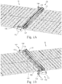
- FIGs. 2A, 2B , and 3 one side of the vehicle 100 is shown on the solar panel array 10 (the control housing 112 is removed for ease of viewing).
- Figs. 2A, 2B , and 3 illustrate only one side of the vehicle, the opposite side is arranged in a generally the same manner.
- the carriage 102 supports axle 106.
- First wheel 108 contacts an upper surface of the solar panel array 10 and is axially aligned with and coupled to axle 106.
- the cleaning element 114 is supported by the carriage 102 and disposed on a first side of axle 106.
- the adjustable couple 120 and third wheel 116 are disposed on an opposite side of the axle 106.
- the adjustable couple 120 and traveler wheel 116 are spaced a distance D1 from the axle 106 and the cleaning element 114 is spaced a distance D2 from the axle 106 (i.e., the third wheel 116 is located further away from the cleaning element than the first wheel 108).
- the weight (W) of the cleaning element 114 results in a rotational force R1 about the axle 106 in a first direction.
- the third wheel 116 is in contact with an underside of the solar panel 10. Accordingly, the force between the third wheel 116 and the underside of the solar panel result in a rotational force R2 about the axle 106 that is in an opposite direction of the rotation force R1 caused by the cleaning element 114.
- F1 and F2 are the reaction forces experienced by the traveler wheel and drive wheels, respectively.
- the cleaning element 114 is cantilevered to the front side of the vehicle with respect to axle 106 and first wheel 108 so that the vehicle is "front heavy.” Since the third wheel 116 counteracts the force generated by the cantilevered mounting of the cleaning element 114, the adjustment of the third wheel 116 can affect the positioning of the cleaning element 114, as discussed in more detail below.
- the third wheel 116 extends below the carriage 102 so that the third wheel 116 can contact an underside of the solar panel array 10 while the first wheel 108 contacts the upper side of the array.
- the third wheel 116 is coupled to the carriage 102 via an adjustable couple 120.
- the adjustable couple includes a first frame member 124 attached to the carriage 102 and a second frame member 126 to which the third wheel 116 is connected.
- Supports 128 and 130 extend between the first and second frame members 124, 126. The two supports 128 and 130 prevent undesired rotation between the frame 126 and the rest of the vehicle in order to maintain alignment of the third wheel 116.
- One of the supports 130 can be threaded and connected to the frame 124 such that rotation of handle 132 causes rotation of the threaded support 130 and results in a change in the distance A between the two frame members 124 and 126. Adjusting the distance between the two frame members 124, 126 causes the third wheel 116 to move with respect to the drive wheel 10 (i.e., in the frame of reference of the vehicle, the total vertical distance between the traveler wheel and drive wheel is changed because the attachment point for the traveler wheel is moved with respect to the vehicle).
- the vehicle can then rotate about the first wheel 108 in the direction M such that the cleaning element 114 is lowered with respect to the top surface of the solar panel array, as show in Fig. 2B . If the support 130 is adjusted such that the distance between the two frame members 124, 126 is decreased (i.e., A2 is less than A1), the vehicle can rotate about the first wheel 108 in the opposite direction such that the cleaning element 114 is raised with respect to the top surface of the solar panel array.
- the ability to lower or raise the cleaning element 114 relative to the solar panel surface allows for adjustment of the amount of contact between the cleaning element 114 (e.g., filaments of a rotating brush) and the panel surface in the field.
- This structure which allows for this kind of adjustment is useful both during initial setup as well as during maintenance as the cleaning element 114 (e.g., brush filaments) can wear down over time.
- the solar panel 10 is disposed between the first wheel 108 and the third wheel 116.
- the third wheel 116 can have a concave surface profile 134 such that profile complements the bottom edge 14 of the solar panel.
- the third wheel 116 can contact both a bottom surface 16 of the solar panel in addition to a side surface 18 of the solar panel.
- the traveler wheel can provide force in both the vertical and horizontal directions. This structural arrangement permits the traveler wheel to act as a guide which provides a normal force outwards on each side of the solar panel.
- the adjustable support 120 allows for the adjustment of the traveler wheel, which provides for the raising and lowering of the cleaning element through a rotation action of the vehicle.
- the adjustment provided by the adjustable support 120 also enables the vehicle to couple to solar panel arrays and/or guide tracks of differing thickness and geometries. Accordingly, the vehicle can be adjusted to couple to thicker solar panels by adjusting the adjustable support 120 which permits increasing the spacing between the frame members 124, 126. Conversely, the spacing can be reduced to accommodate thinner solar panels.
- the vehicle 100 includes a control housing 112 that includes at least one motor for providing drive power to the vehicle.
- the motor can be coupled to the axle 106 in order to transmit power from the motor to the first wheel 108.
- the cleaning element 114 can be coupled to the axle 106 so that the power from the motor can also be transmitted to the cleaning element to rotate the cleaning element.
- a power transmission system 136 can couple the axle 106 and the cleaning element 114 so that power from the motor can be used to both rotate the first wheel 108 (causing the vehicle to translate across the surface of the solar panel) and also rotate the cleaning element (causing the cleaning element to remove debris from the surface of the solar panel).
- the power transmission system 136 can include a gear 138 connected to the axle 106 and a belt drive system 140 that couples the cleaning element 114 to the gear 138. Accordingly, as the axle 106 rotates, the gear 138 rotates which causes the belt drive system 140 to rotate, resulting in rotation of the cleaning element 114.
- the power transmission system 136 is structured and arranged such that the drive wheel 108 and the cleaning element 114 rotate in opposite directions. As such, the cleaning element rotates opposite to the direction in which the linear motion of the vehicle occurs. As the wheels drive forward, the reverse direction of rotation of the cleaning element results in more effective cleaning.
- the opposite rotation of the cleaning element counteracts the torque generated by driving the drive wheels.
- the motor applies a torque to drive the vehicle forward
- the vehicle's body will react tending to do a 'wheelie,' i.e., the brush tends to lift from the surface.
- the drive wheels and the cleaning element are coupled to the motor, a counteracting effect results in the same manner, but with an opposite direction. This effect is due to the torque required to drive the brush, and in particular to the torque required to start driving it, and the fact that the brush is moving opposite to the wheels. As a result, depending on which torque requirement is higher (i.e.
- the vehicle will experience either one of a 'wheelie' or a 'diving' effect.
- the torque required to drive the cleaning element is typically higher than the torque needed to drive the wheels and, therefore, the vehicle tends to dive forward as it accelerates forward (i.e., the cleaning element is urged toward the surface of the solar panel as a result of the torque).
- While a single motor may be used to rotate the drive wheels and the cleaning element, as discussed above, other motor arrangements are possible. As it typically requires more power to drive the cleaning element than it does to drive the wheels, arranging the motor to drive the cleaning element directly and the drive wheel indirectly using a power transmission system can lower the cost of the power transmission elements as they'd need to transfer less power and could therefore be smaller. On the other hand, shifting the motor to the front of the vehicle (i.e., proximate the cleaning element) will also shift the weight distribution of the vehicle and, in some cases, this may not be desired. It is also possible to drive the drive wheels and the cleaning element separately, either using separate motors for each and a clutching mechanism.
- one possible benefit is that the cleaning element is not rotated after the vehicle completes its cleaning pass and is returning to its starting position as this will reduce power consumption and reduce wear on the cleaning element and panels.
- one motor can drive the brush and a second motor can drive only one of the drive wheels (i.e., the other drive wheel is coupled to the axle for free rotation and not driven rotation).
- Three motors can also be used in which each drive wheel is driven by its own motor and the brush is driven by the third motor. It is also possible to use motors to drive the traveler wheels in addition to or instead of the drive wheels (in this case, the brush is driven by another motor).
- the third and fourth wheels 116, 118 can have a concave surface 134 that contacts both a horizontal and vertical surface (e.g., a bottom and a side) of the solar panel.
- a guide assembly can be provided on each side of the vehicle that includes two rollers. In a two roller (per side) arrangement, one roller contacts the side of the solar panel and the other roller contacts the underside of the solar panel.
- the two guide roller arrangement functions similar to the traveler wheel having a convex surface in that two guide rollers provide vertical and horizontal forces to counteract the weight (W) of the cleaning element 114 and maintain the vehicle coupled to and aligned with the solar panel while minimizing friction as the vehicle travels along the surface.
- a second set of side rollers can be included on the vehicle located closer to the side of the vehicle having the cleaning element (e.g. in the vicinity of the F2 Arrowhead in Fig. 2A ). This additional set of side rollers further assists in maintaining the vehicle in alignment with the solar panel array, especially in cases in which the vehicle spans wide or multiple solar panels.
- the vehicle 100 can be widened to span multiple solar panels.
- Each of the carriages 102, 104 of the vehicle can couple to the outermost side of the outermost solar panel in the array.
- the vehicle can clean multiple solar panels in a single pass.
- the axle and cleaning element can be elongated to accommodate the width of the solar panel(s).
- a frame member 142 can extend between the two carriages to provide additional structural support so that the carriages move together and maintain alignment.
- the vehicle has a certain degree of "bounciness" as it traverses the panels.
- This bounciness comes from a combination of the materials used in the drive and traveler wheels and of any bumps or protrusions that the wheels might encounter. For example, harder materials will result in a stiffer vehicle structure while softer, rubber-like materials will act as a spring-suspension and provide some bounciness (polyurethane coated wheels with a Shore A hardness of 60A for the drive wheels and 40A for the traveler wheels can be used).
- the height of the cleaning element relative to the surface will vary slightly as the wheels of the vehicle overcome obstacles or protrusions such as the edges of the panel frames, the gaps between panels, misalignment between one panel and the next or even some debris on the panels such as hardened bird feces or accumulated sand. Since the traveler wheels can be flexible and perform like a spring-suspension, the reduction in force required to hold the cleaning element up (due to the normal force created by the interaction of the cleaning element and the surface) causes the system to dynamically balance in a position that is higher than if there was no normal force between the cleaning element and the panels (i.e., if the cleaning element were not touching the panel). Therefore, the vehicle allows for a small degree of automatic adjustment.
- the cleaning element 114 can be a brush with bristles or a cloth brush instead of using plastic filaments. If a cloth cleaning element is used, the normal force on the cleaning element might be much less significant (negligible if the cleaning element were not spinning).
- the distance D1 between the drive wheels and the traveler wheels can be reduced to zero (i.e., the first wheel 108 can be vertically aligned with the third wheel 116).
- the present design is unique in that it puts the cleaning element in front of the wheels of the vehicle, solving a problem of reaching the end of the surface to be cleaned. Additionally, this arrangement reduces the number of moving parts on the cleaning vehicle, thus allowing for improved mechanical reliability and reduced cost. Additionally, this design allows us to adjust the cleaning vehicle to fit onto solar panels of various depths, making it easier to use on different systems with very little modification.
- the vehicle is designed to ride directly on the edges of standard PV (photovoltaic) solar panel modules and that no additional tracks are required.
- the present design is suitable for use on both framed as well as frameless PV modules.
- the wheels of the vehicle simply ride directly on the Aluminum frame on the PV modules.
- the wheels of the vehicle will ride directly on the module's main glass panel.
- the designer should consider the strength of the panel and strike a balance in the design parameters to ensure that the moment exerted by the vehicles wheels (on account of it being front heavy) will not break the glass.
- the roller can be rotated outwards on the remaining support bar, for easier mounting in the case that the robot cleaning device cannot be rolled onto the end of the panels.
- the vehicle can include an adjustment screw for adjusting the height of the bottom wheel (traveler wheels). This in turn results is: a) the ability to adjust the vehicle to work on different types of solar panels (with different frame heights) while on the field; and b) the ability to lower or raise the brush relative to the panel surface to control the amount of contact between the brush filaments and the panel surface on the field (this is useful both during initial setup as well as during maintenance as the brush filaments wear down over time). As described herein, there is a moment created by the reaction forces F1 and F2 as it can be controlled by a user changing D1, D2 and other vehicle design parameters.
- the user will look at the statics and dynamics of the vehicle and make sure that there is enough traction out of both wheels and also the wheel material is selected in order to obtain the desired springy nature thereof. It will also be appreciated that the "lower" of the bottom wheel using the adjustment screw does not result in the bottom wheel moving its position but instead, the attachment point between the bottom roller and the rest of vehicle rises away from the roller, thus allowing the brush to lower as the vehicle tilts forward.
- the "traveler wheels" can take any number of different configurations and arrangements.
- Fig. 3 shows a single traveler wheel (i.e., the third wheel 116)
- Fig. 4 more than one traveler wheel can be associated with and coupled to each carriage as discussed below.
- the wheels are not limited to having a concave or V-shaped construction and other constructions can equally be used.
- the wheels have smooth circular shaped outer surfaces.
- Fig. 4 shows a vehicle 200 with a first carriage 210 (similar to carriage 104) and a second carriage 212 (similar to carriage 102) being spaced therefrom and coupled thereto by a cross support member 219.
- the cross support member 219 can be in the form of an elongated support structure that is attached (fastened) at its ends to the first and second carriages 210, 212.
- the cross support member 219 has a forward face 222 and a rear face 224.
- each of the first and second carriages 210, 212 has a forward facing end and a rearward facing end.
- the cross support member 219 can be formed of any number of different materials, including but not limited to metals, rigid plastics, etc.
- each of the carriages 210, 212 has a downwardly extending arm 211.
- one or more holes 213 are formed.
- the illustrated embodiment has three spaced holes 213 along the arm 211.
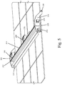
- each of the first and second carriages 210, 212 includes a side roller 220 and a bottom (up-stop) roller 230. While Figs. 4 and 5 show a single side roller 220 and a single bottom roller 230 being used, it will be understood that more than one side roller 220 and more than one bottom roller 230 can be used (See, Fig. 6 which eliminates a bracket to show the wheel 110). In this example, not part of the present invention, the roller 220 and roller 230 are not adjustable unlike the previous embodiment. More specifically, the side roller 220 is mounted on an axle (that is oriented perpendicular to the longitudinal axis of the carriage) and is positioned such that the contacting surface of the side roller contacts a side wall of the panel 10. The bottom roller 230 is mounted on an axle (that is oriented parallel to the longitudinal axis of the carriage) and is positioned such that the contacting surface of the bottom roller contacts a bottom wall of the panel 10.
- the holes 213 allow for different positioning of the bottom roller 230 relative one of the respective first and second wheels 108, 110, thereby accommodating panels 10 having different thicknesses.
- Figs. 4 and 5 also show an arrangement in which only one of the first and second wheels 108, 110 is driven and in particular, in the illustrated embodiment, the second roller 110 is the one which is driven.
- the second wheel 110 is mounted to a first wheel support 240 (similarly, the first wheel is mounted to an identical or similar second wheel support (not shown) that is mounted to the carriage 210).
- Each of the first and second wheel supports 240 can be in the form of a bracket which attaches at its ends to an inner face of the corresponding carriage 210, 212.
- the first wheel 108 is rotatably positioned between the first wheel support 240 and the first carriage 210 and the second wheel 110 is rotatably positioned between the second wheel support 242 and the second carriage 212.
- a first motor 250 is operably coupled to the first wheel 108 to control rotation thereof.
- the first motor 250 is mounted along an outer face of the first carriage 210.
- a second motor 252 is also mounted to the outer face of the first carriage 210 and is operably coupled to the cleaning element 114 to controllably rotate the cleaning element 114.
- the other wheels along the top of the panel 10 are passive (slave) wheels.
- the second wheel 110 is thus not directly driven by the motor 250 (i.e., no power transmission to the second wheel 110).
- the cleaning element 114 and first wheel 108 are independently driven by motors 252, 250, respectively, there is not power transmission between the cleaning element 114 and the drive wheel (i.e., wheel 108).
- Figs. 4 and 5 also show that the vehicle 200 includes an additional optional top wheel, namely, a fifth wheel 260.
- the fifth wheel 260 is a passive wheel and is not actively driven by a motor.
- the fifth wheel 260 can be mounted to the cross support member 219 and more particularly, the fifth wheel 260 is mounted to a wheel bracket 270 (e.g., U-shaped bracket) that is attached to the rear face 224.
- the fifth wheel 260 in the illustrated embodiment is centrally located along the cross support member 220.
- the first, second and fifth wheels 108, 110, 260 are all oriented such that a single axis passes through the axles about which the wheels rotate. This arrangement ensures that when the vehicle 200 is placed on the top of the panel 10, each of the wheels 108, 110, 260 seats against the top of the panel 10.
- the fifth wheel 260 is thus positioned to provide support for weight if needed.
- Fig. 6 shows another vehicle 300 that is constructed to include two side rollers 220 and one bottom (up-stop) roller 230 per each carriage.
- the two side rollers 220 are spaced apart with one top wheel being at least partially disposed between the two side rollers 220.
- the one bottom roller 230 is located at the rear end of the carriage.
Claims (14)
- Reinigungsfahrzeug (100) zur Reinigung einer Fläche eines Objekts, umfassend:- einen ersten und zweiten Wagen (102, 104);- ein erstes und zweites Rad (108, 110), die jeweils mit dem ersten beziehungsweise zweiten Wagen (102, 104) gekoppelt sind, zur Platzierung entlang einer oberen Fläche des Objekts;- mindestens einen Motor, der operativ mit mindestens einem von dem ersten und zweiten Rad (108, 110) gekoppelt ist, um eine Antriebseinheit zu definieren;- ein Reinigungselement (114), das sich zwischen dem ersten und zweiten Wagen (102, 104) erstreckt und von diesen gestützt wird;- ein drittes und viertes Rad (116, 118), die sich jeweils unter dem ersten beziehungsweise zweiten Wagen (102, 104) erstrecken; und- eine erste einstellbare Kupplung (120), die mit dem ersten Wagen (102) gekoppelt ist, und eine zweite einstellbare Kupplung (122), die mit dem zweiten Wagen (104) gekoppelt ist, wobei die erste einstellbare Kupplung (120) einen ersten Abstand zwischen dem ersten Wagen (102) und dem dritten Rad (116) definiert, und die zweite einstellbare Kupplung (122) einen zweiten Abstand zwischen dem zweiten Wagen (104) und dem vierten Rad (118) definiert, wobei der erste und zweite Abstand bemessen sind, um mindestens einen Abschnitt des Objekts aufzunehmen, um das Fahrzeug (100) auf der zu reinigenden Fläche zu positionieren;wobei- das Reinigungselement (114) auf einer Seite einer Achse angeordnet ist, die zentral durch das erste und zweite Rad (108, 110) hindurchgeht und davon um eine erste Distanz beabstandet ist;- das dritte und vierte Rad (116, 118) auf einer gegenüberliegenden Seite der Achse angeordnet sind und davon um eine zweite Distanz beabstandet sind;dadurch gekennzeichnet, dass:- die erste und zweite einstellbare Kupplung (120, 122) jeweils ein erstes Rahmenelement (124), das an dem jeweiligen Wagen (102, 104) angebracht ist, und ein zweites Rahmenelement (126), mit dem das jeweilige dritte Rad (116) oder vierte Rad (118) verbunden ist, umfassen, wobei sich Stützen (128, 130) zwischen dem ersten und zweiten Rahmenelement (124, 126) erstrecken und eingestellt werden können, wodurch eine Distanz zwischen dem ersten und zweiten Rahmenelement (124, 126) eingestellt wird, was bewirkt, dass sich das dritte und vierte Rad (116, 118) jeweils in Bezug auf das erste beziehungsweise zweite Rad (108, 110) bewegen, sodass die Bewegung des dritten und vierten Rads (116, 118) zum Abheben oder Absenken des Reinigungselements (114) in Bezug auf die Fläche des Objekts führt.
- Reinigungsfahrzeug nach Anspruch 1, wobei das Objekt ein Solarpaneel umfasst, und die Fläche eine obere Fläche (12) davon umfasst, und das erste und zweite Rad (108, 110) und das Reinigungselement (114) mit der zu reinigenden Fläche in Kontakt gelangen.
- Reinigungsfahrzeug nach Anspruch 2, wobei das Solarpaneel ferner eine Bodenfläche (16) und ein Paar gegenüberliegender Seitenflächen (18) aufweist, die sich zwischen der oberen und der Bodenfläche (12, 16) erstrecken.
- Reinigungsfahrzeug nach Anspruch 3, wobei das dritte Rad (116) sowohl gegen eine Seitenfläche (18) als auch die Bodenfläche (16) sitzt, und das vierte Rad (118) sowohl gegen die andere Seitenfläche (18) als auch die Bodenfläche (16) sitzt.
- Reinigungsfahrzeug nach Anspruch 1, wobei jedes von dem dritten und vierten Rad (116, 118) eine von einer konkaven Form und einer V-Form aufweist.
- Reinigungsfahrzeug nach Anspruch 1, ferner umfassend eine Achse (106), die sich zwischen dem ersten und zweiten Wagen (102, 104) erstreckt und mit dem ersten und zweiten Rad (108, 110) gekoppelt ist, wobei der Motor ausgelegt ist, die Achse (106) zu drehen, um so zu bewirken, dass sich das erste und zweite Rad (108, 110) in einer ersten Richtung drehen.
- Reinigungsfahrzeug nach Anspruch 6, wobei der Motor an einem von dem ersten und zweiten Wagen (102, 104) montiert ist.
- Reinigungsfahrzeug nach Anspruch 6, wobei das Reinigungselement (114) relativ zu einer Vorderseite des Fahrzeugs (100) in Bezug auf die Achse (106) und das erste und zweite Rad (108, 110) auskragt, wodurch bewirkt wird, dass das Fahrzeug (100) vorderlastig ist, und wobei die erste und zweite einstellbare Kupplung (120, 122) derart ausgelegt sind, dass eine Änderung des ersten und zweiten Abstands zwischen jeweils dem ersten und zweiten Wagen (102, 104) und dem dritten und vierten Rad (116, 118) bewirkt, dass sich das Reinigungselement (114) um die Achse (106) dreht.
- Reinigungsfahrzeug nach Anspruch 1, wobei das Reinigungselement (114) eine Bürste mit Borsten umfasst.
- Reinigungsfahrzeug nach Anspruch 6, wobei das Reinigungselement (114) operativ mit der Achse (106) gekoppelt ist, sodass eine Drehung der Achse (106) in eine Drehung des Reinigungselements (114) übersetzt wird.
- Reinigungsfahrzeug nach Anspruch 10, wobei die operative Kupplung zwischen dem Reinigungselement (114) und der Achse (106) mit einem Getriebesystem (136) erzielt wird, das die Achse (106) mit dem Reinigungselement (114) derart koppelt, dass Leistung von dem mindestens einen Motor (250) sowohl das erste und zweite Rad (108, 110) als auch das Reinigungselement (114) dreht.
- Reinigungsfahrzeug nach Anspruch 6, wobei das Getriebesystem (136) ein Zahnrad (138), das mit der Achse (106) verbunden ist, und ein Riemenantriebssystem (140) aufweist, welches das Reinigungselement (114) mit dem Zahnrad (138) derart koppelt, dass die Drehung der Achse (106) in eine Drehung des Zahnrads (138) übersetzt wird, die ihrerseits bewirkt, dass sich das Riemenantriebssystem (140) dreht, was zur Drehung des Reinigungselements (114) führt.
- Reinigungsfahrzeug nach Anspruch 1, wobei sich das erste und zweite Rad (108, 110) in einer ersten Richtung drehen, während sich das Reinigungselement (114) in einer entgegengesetzten zweiten Richtung dreht.
- Reinigungsfahrzeug nach Anspruch 1, wobei, wenn das Fahrzeug (100) in einer Vorwärtsrichtung angetrieben wird, das erforderliche Drehmoment zur Beschleunigung des Fahrzeugs (100) geringer ist als das erforderliche Drehmoment zur Drehung des Reinigungselements (114), und daher, wenn das Fahrzeug (100) vorwärts fährt, das Fahrzeug vorwärts abtaucht, wodurch bewirkt wird, dass das Reinigungselement (114) gegen die zu reinigende Fläche gedrückt wird, und umgekehrt, wenn das Fahrzeug (100) in einer Rückwärtsrichtung angetrieben wird, umgekehrte Drehmomentrichtungen bewirken, dass das Reinigungselement (114) von der zu reinigenden Fläche weg abgehoben wird.
Priority Applications (1)
| Application Number | Priority Date | Filing Date | Title |
|---|---|---|---|
| EP19176064.4A EP3550220B1 (de) | 2015-08-24 | 2016-08-18 | Vorderlastiges staubreinigungsfahrzeug |
Applications Claiming Priority (2)
| Application Number | Priority Date | Filing Date | Title |
|---|---|---|---|
| US201562209047P | 2015-08-24 | 2015-08-24 | |
| PCT/US2016/047561 WO2017034921A2 (en) | 2015-08-24 | 2016-08-18 | Front-heavy dust cleaning vehicle |
Related Child Applications (2)
| Application Number | Title | Priority Date | Filing Date |
|---|---|---|---|
| EP19176064.4A Division EP3550220B1 (de) | 2015-08-24 | 2016-08-18 | Vorderlastiges staubreinigungsfahrzeug |
| EP19176064.4A Division-Into EP3550220B1 (de) | 2015-08-24 | 2016-08-18 | Vorderlastiges staubreinigungsfahrzeug |
Publications (2)
| Publication Number | Publication Date |
|---|---|
| EP3341660A2 EP3341660A2 (de) | 2018-07-04 |
| EP3341660B1 true EP3341660B1 (de) | 2019-07-24 |
Family
ID=56926261
Family Applications (2)
| Application Number | Title | Priority Date | Filing Date |
|---|---|---|---|
| EP19176064.4A Active EP3550220B1 (de) | 2015-08-24 | 2016-08-18 | Vorderlastiges staubreinigungsfahrzeug |
| EP16766112.3A Not-in-force EP3341660B1 (de) | 2015-08-24 | 2016-08-18 | Vorderlastiges staubreinigungsfahrzeug |
Family Applications Before (1)
| Application Number | Title | Priority Date | Filing Date |
|---|---|---|---|
| EP19176064.4A Active EP3550220B1 (de) | 2015-08-24 | 2016-08-18 | Vorderlastiges staubreinigungsfahrzeug |
Country Status (8)
| Country | Link |
|---|---|
| US (2) | US10305420B2 (de) |
| EP (2) | EP3550220B1 (de) |
| JP (2) | JP6896706B2 (de) |
| KR (2) | KR102188786B1 (de) |
| CN (2) | CN108139117B (de) |
| ES (1) | ES2747397T3 (de) |
| SA (1) | SA521421707B1 (de) |
| WO (1) | WO2017034921A2 (de) |
Families Citing this family (26)
| Publication number | Priority date | Publication date | Assignee | Title |
|---|---|---|---|---|
| CN105834188B (zh) * | 2016-05-13 | 2017-03-22 | 北京中电博顺智能设备技术有限公司 | 一种光伏板清洗设备 |
| US9923513B2 (en) * | 2016-05-13 | 2018-03-20 | Boson Robotics Ltd. | Cleaning mechanism having water spray function and photovoltaic panel cleaning equipment having same |
| CN211678936U (zh) | 2016-07-08 | 2020-10-16 | 欧烁灵公司 | 表面清洁设备 |
| EP3676955A1 (de) * | 2017-08-30 | 2020-07-08 | SunPower Corporation | Automatische reinigungsvorrichtung für sonnenkollektoren |
| CN107626631A (zh) * | 2017-10-24 | 2018-01-26 | 维科诚(苏州)光伏科技有限公司 | 一种光伏组件清洗设备 |
| KR102063561B1 (ko) * | 2017-12-21 | 2020-02-11 | (주)디엠비에이치 | 집진 청소용 로봇 |
| ES2965511T3 (es) * | 2017-12-28 | 2024-04-15 | Weismacher Eco Private Ltd | Sistema de limpieza de panel solar autoalimentable y basado en temporizador |
| WO2019167079A1 (en) * | 2018-03-01 | 2019-09-06 | Mohan Suraj | Automatic cleaning vehicle for photovoltaic panels |
| CN108609541A (zh) * | 2018-07-06 | 2018-10-02 | 湖州吉弘机械有限公司 | 一种便于清理的叉车用货叉 |
| US11638939B2 (en) * | 2018-11-27 | 2023-05-02 | Steam Tech, Llc | Mobile panel cleaner |
| US11020772B2 (en) * | 2019-02-05 | 2021-06-01 | William F. Crunk | System and method for cleaning wind turbine blades and solar panels |
| DE202019101423U1 (de) * | 2019-03-13 | 2020-06-16 | Franz Ehleuter | Vorrichtung zur Behandlung glatter Flächen, insbesondere der Oberfläche von Photovoltaik- und Solaranlagen |
| USD938114S1 (en) * | 2019-03-22 | 2021-12-07 | Sungrow Power Supply Co., Ltd. | Intelligent cleaning robot |
| KR102327890B1 (ko) * | 2019-05-08 | 2021-11-17 | 호산이엔씨 주식회사 | 다기능 태양광 패널 청소 장치 |
| CN110332721B (zh) * | 2019-06-21 | 2021-01-12 | 浙江中控太阳能技术有限公司 | 一种定日镜的自清洁装置 |
| CN110560404B (zh) * | 2019-09-30 | 2020-12-22 | 北京中电博顺智能设备技术有限公司 | 一种光伏板清洁机器人及其控制方法 |
| CN110548706A (zh) * | 2019-09-30 | 2019-12-10 | 国网河南省电力公司洛宁县供电公司 | 一种太阳能电池板的清扫装置 |
| CN110953646A (zh) * | 2019-11-26 | 2020-04-03 | 广州市婵昕生物科技有限责任公司 | 一种具有过滤功能的高效型太阳能地暖 |
| CN111299195A (zh) * | 2019-11-29 | 2020-06-19 | 吉林大学 | 一种清洁装置、太阳能电池板系统及其控制方法 |
| WO2021183699A1 (en) * | 2020-03-10 | 2021-09-16 | Escobedo Christopher | Systems for cleaning and analysis of nonporous surfaces |
| US20220000255A1 (en) * | 2020-07-02 | 2022-01-06 | Eugene Saint-Jean, JR. | Mobile Trailer-Cleaning System |
| CN113726284A (zh) * | 2020-11-23 | 2021-11-30 | 吴碧玉 | 多功能太阳能光伏组件 |
| CN112910404B (zh) * | 2021-01-19 | 2022-04-15 | 黄山富乐新能源科技有限公司 | 一种戈壁用光伏发电板 |
| CN113134481B (zh) * | 2021-03-30 | 2022-07-01 | 湖南腾发新能源有限公司 | 一种光伏太阳能板清理装置 |
| KR102357644B1 (ko) * | 2021-08-02 | 2022-02-09 | 조득제 | 태양광 집광판 청소장치 |
| CN115005715A (zh) * | 2022-07-15 | 2022-09-06 | 北京顺造科技有限公司 | 一种地刷的助力装置、地刷组件及湿式表面清洁设备 |
Family Cites Families (30)
| Publication number | Priority date | Publication date | Assignee | Title |
|---|---|---|---|---|
| US3194178A (en) | 1963-09-13 | 1965-07-13 | Martin E Weston | Wheel assembly for a monorail |
| JPH0929195A (ja) | 1995-07-21 | 1997-02-04 | Ke Corp:Kk | マット洗浄機 |
| JPH10324077A (ja) | 1997-03-25 | 1998-12-08 | Toshiyuki Niimura | 物品表面清掃装置 |
| US6047645A (en) | 1998-06-26 | 2000-04-11 | Setpoint Engineered Systems, Inc. | Truss track assembly and side mount roller coaster vehicle |
| US6883201B2 (en) | 2002-01-03 | 2005-04-26 | Irobot Corporation | Autonomous floor-cleaning robot |
| JP4843167B2 (ja) * | 2001-09-20 | 2011-12-21 | 株式会社東芝 | ローラ清掃装置 |
| US7082639B2 (en) | 2001-10-19 | 2006-08-01 | Tennant Company | Brush optimizer |
| CA2609141C (en) * | 2005-05-20 | 2013-11-26 | William J. Kitchen | Wheel hub rider conveyance |
| KR101275303B1 (ko) * | 2009-06-23 | 2013-06-14 | 이상현 | 집광판의 세정장치 |
| DE102010008131B4 (de) | 2009-07-24 | 2011-09-15 | Scansonic Mi Gmbh | Reinigungsvorrichtung |
| WO2011161696A2 (en) * | 2010-06-21 | 2011-12-29 | Indian Instutute Of Technology, Bombay | Sun tracking mechanism with automated cleaning arrangement for solar panel |
| ES2435445T3 (es) | 2010-10-01 | 2013-12-19 | Manu Systems Ag | Dispositivo de servicio para la limpieza y el mantenimiento de una disposición de paneles solares |
| CN102124921B (zh) * | 2011-01-30 | 2013-11-27 | 河南方孔实业有限公司 | 透镜大棚光靶联动太阳能收集装置 |
| WO2012123979A2 (en) | 2011-03-14 | 2012-09-20 | Preziuso Benvenuto Mchele | Solar panel cleaning apparatus |
| ITTV20110163A1 (it) | 2011-12-01 | 2013-06-02 | Tendital Di Zanatta F & C Snc | Dispositivo automatico per il lavaggio di superfici continue quali pannelli solari/fotovoltaici e vetri in facciate continue, dotato di spazzola rotante, motore, telaio e dispositivo di avanzamento caratterizzato dalla presenza di un albero di torsio |
| DE102012002900A1 (de) * | 2012-02-14 | 2013-08-14 | Anton Jäger | Reinigungsvorrichtung |
| US8500918B1 (en) * | 2012-05-15 | 2013-08-06 | Ecoppia Scientific, Ltd. | Solar panel cleaning system and method |
| US8771432B2 (en) * | 2012-05-15 | 2014-07-08 | Ecoppia Scientific, Ltd. | Solar panel cleaning system and method |
| EP2695683A1 (de) * | 2012-08-06 | 2014-02-12 | Chemik Innovacion y Desarrollos S.L. | Vorrichtung zur Wartung flacher Elemente, insbesondere Sonnenkollektoren |
| FR2997875B1 (fr) * | 2012-11-09 | 2016-02-05 | Constructions Ind De La Mediterranee Cnim | Dispositif permettant de nettoyer les surfaces reflechissantes de miroirs d'une installation solaire |
| JP6168679B2 (ja) | 2013-03-29 | 2017-07-26 | 株式会社コーワ | 着脱式ソーラーパネル清掃装置 |
| AU2014288933B2 (en) * | 2013-07-05 | 2018-03-08 | King Abdullah University Of Science And Technology | System and method for conveying an assembly |
| US8813303B1 (en) * | 2013-08-28 | 2014-08-26 | Ecoppia Scientific, Ltd. | Descent control and energy recovery system for solar panel cleaning system |
| DE202013008573U1 (de) * | 2013-09-26 | 2013-10-25 | Anton Jäger | Führungsvorrichtung |
| DE102013219460A1 (de) | 2013-09-26 | 2015-03-26 | Anton Jäger | Reinigungsvorrichtung |
| WO2015083149A1 (en) * | 2013-12-04 | 2015-06-11 | Ram Ido | Pressure driven automated solar panel cleaning system |
| US20150349706A1 (en) * | 2014-06-03 | 2015-12-03 | Sunpower Corporation | Solar module cleaner |
| US9130502B1 (en) * | 2014-12-15 | 2015-09-08 | King Fahd University Of Petroleum And Minerals | Photovoltaic panel cleaning machine |
| US20160178241A1 (en) * | 2014-12-22 | 2016-06-23 | Sunpower Corporation | Solar module cleaner |
| US9455665B1 (en) * | 2015-11-08 | 2016-09-27 | Ecoppia Scientific Ltd. | Solar tracker cleaning system and method |
-
2016
- 2016-08-18 US US15/240,601 patent/US10305420B2/en active Active
- 2016-08-18 JP JP2018510436A patent/JP6896706B2/ja active Active
- 2016-08-18 KR KR1020187007807A patent/KR102188786B1/ko active IP Right Grant
- 2016-08-18 EP EP19176064.4A patent/EP3550220B1/de active Active
- 2016-08-18 CN CN201680056661.3A patent/CN108139117B/zh not_active Expired - Fee Related
- 2016-08-18 CN CN201911111069.0A patent/CN110822739A/zh active Pending
- 2016-08-18 KR KR1020207034815A patent/KR20200138452A/ko active IP Right Grant
- 2016-08-18 WO PCT/US2016/047561 patent/WO2017034921A2/en active Application Filing
- 2016-08-18 ES ES16766112T patent/ES2747397T3/es active Active
- 2016-08-18 EP EP16766112.3A patent/EP3341660B1/de not_active Not-in-force
-
2018
- 2018-01-31 SA SA521421707A patent/SA521421707B1/ar unknown
-
2019
- 2019-04-17 US US16/386,881 patent/US11183966B2/en active Active
-
2021
- 2021-06-09 JP JP2021096592A patent/JP2021175571A/ja not_active Withdrawn
Non-Patent Citations (1)
| Title |
|---|
| None * |
Also Published As
| Publication number | Publication date |
|---|---|
| EP3550220A1 (de) | 2019-10-09 |
| EP3341660A2 (de) | 2018-07-04 |
| KR20200138452A (ko) | 2020-12-09 |
| CN108139117A (zh) | 2018-06-08 |
| CN110822739A (zh) | 2020-02-21 |
| ES2747397T3 (es) | 2020-03-10 |
| US11183966B2 (en) | 2021-11-23 |
| JP2018528071A (ja) | 2018-09-27 |
| JP2021175571A (ja) | 2021-11-04 |
| WO2017034921A2 (en) | 2017-03-02 |
| JP6896706B2 (ja) | 2021-06-30 |
| KR20180044326A (ko) | 2018-05-02 |
| CN108139117B (zh) | 2019-12-10 |
| EP3550220B1 (de) | 2020-12-02 |
| KR102188786B1 (ko) | 2020-12-08 |
| SA521421707B1 (ar) | 2022-02-07 |
| WO2017034921A3 (en) | 2017-04-20 |
| US20190245481A1 (en) | 2019-08-08 |
| US20170063293A1 (en) | 2017-03-02 |
| US10305420B2 (en) | 2019-05-28 |
Similar Documents
| Publication | Publication Date | Title |
|---|---|---|
| EP3341660B1 (de) | Vorderlastiges staubreinigungsfahrzeug | |
| KR101276069B1 (ko) | 솔라 패널 설비의 유지관리를 위한 서비스 장치 | |
| JP2018528071A5 (de) | ||
| EP3208021A1 (de) | Vorrichtung zum drahttrennläppen von blöcken, walzenmodul dafür und verfahren zum trennläppen von blöcken | |
| CN211579918U (zh) | 一种带有清洁功能的太阳能光伏支架 | |
| CN103930983A (zh) | 用于清洁光电器件的装置和方法 | |
| WO2018195291A1 (en) | Systems and methods for cleaning arrays of solar panels | |
| WO2014185082A1 (ja) | 洗浄装置 | |
| KR102057819B1 (ko) | 태양광패널 자동 세척장치 | |
| JP6166597B2 (ja) | 洗浄装置 | |
| CN214591264U (zh) | 一种具有除尘功能的分布式太阳能光伏装置 | |
| CN211707477U (zh) | 一种导光板自动清洁装置 | |
| CN113247584A (zh) | 一种用于光电显示自动化设备的翻转机系统 | |
| CN218663726U (zh) | 一种可调节高度具有防护功能的自动化流水线设备 | |
| CN216302883U (zh) | 一种电缆自动输送装置 | |
| CN215967832U (zh) | 一种用于汽车驱动轴的打磨加工装置 | |
| CN218771969U (zh) | 一种太阳能板清洁小车 | |
| CN102285388A (zh) | 行走机器人 | |
| CN216095090U (zh) | 一种电站式光伏板用链轮机器人 | |
| CN218230460U (zh) | 一种玻璃瓶加工用全自动排列装置 | |
| CN213342101U (zh) | 一种高透光率单晶硅太阳能电池板 | |
| CN110841991A (zh) | 一种标准圆形幅流式二沉池全自动清洗机器人 | |
| CN117411418A (zh) | 清扫机器人及其运动控制方法 | |
| CN117051757A (zh) | 一种起重机械轨道清扫装置 | |
| CN117719823A (zh) | 一种单排式物料振动输送机 |
Legal Events
| Date | Code | Title | Description |
|---|---|---|---|
| STAA | Information on the status of an ep patent application or granted ep patent |
Free format text: STATUS: THE INTERNATIONAL PUBLICATION HAS BEEN MADE |
|
| PUAI | Public reference made under article 153(3) epc to a published international application that has entered the european phase |
Free format text: ORIGINAL CODE: 0009012 |
|
| STAA | Information on the status of an ep patent application or granted ep patent |
Free format text: STATUS: REQUEST FOR EXAMINATION WAS MADE |
|
| 17P | Request for examination filed |
Effective date: 20180320 |
|
| AK | Designated contracting states |
Kind code of ref document: A2 Designated state(s): AL AT BE BG CH CY CZ DE DK EE ES FI FR GB GR HR HU IE IS IT LI LT LU LV MC MK MT NL NO PL PT RO RS SE SI SK SM TR |
|
| AX | Request for extension of the european patent |
Extension state: BA ME |
|
| DAV | Request for validation of the european patent (deleted) | ||
| DAX | Request for extension of the european patent (deleted) | ||
| REG | Reference to a national code |
Ref country code: DE Ref legal event code: R079 Ref document number: 602016017439 Country of ref document: DE Free format text: PREVIOUS MAIN CLASS: F24J0002460000 Ipc: F24S0040200000 |
|
| RIC1 | Information provided on ipc code assigned before grant |
Ipc: H02S 40/10 20140101ALI20181220BHEP Ipc: F24S 40/20 20180101AFI20181220BHEP |
|
| GRAP | Despatch of communication of intention to grant a patent |
Free format text: ORIGINAL CODE: EPIDOSNIGR1 |
|
| STAA | Information on the status of an ep patent application or granted ep patent |
Free format text: STATUS: GRANT OF PATENT IS INTENDED |
|
| RIC1 | Information provided on ipc code assigned before grant |
Ipc: F24S 40/20 20180101AFI20181220BHEP Ipc: H02S 40/10 20140101ALI20181220BHEP |
|
| INTG | Intention to grant announced |
Effective date: 20190130 |
|
| RIN1 | Information on inventor provided before grant (corrected) |
Inventor name: PARROTT, BRIAN Inventor name: AISHEHRI, ALI Inventor name: CARRASCO ZANINI, PABLO |
|
| GRAS | Grant fee paid |
Free format text: ORIGINAL CODE: EPIDOSNIGR3 |
|
| GRAJ | Information related to disapproval of communication of intention to grant by the applicant or resumption of examination proceedings by the epo deleted |
Free format text: ORIGINAL CODE: EPIDOSDIGR1 |
|
| GRAL | Information related to payment of fee for publishing/printing deleted |
Free format text: ORIGINAL CODE: EPIDOSDIGR3 |
|
| STAA | Information on the status of an ep patent application or granted ep patent |
Free format text: STATUS: REQUEST FOR EXAMINATION WAS MADE |
|
| GRAR | Information related to intention to grant a patent recorded |
Free format text: ORIGINAL CODE: EPIDOSNIGR71 |
|
| STAA | Information on the status of an ep patent application or granted ep patent |
Free format text: STATUS: GRANT OF PATENT IS INTENDED |
|
| GRAA | (expected) grant |
Free format text: ORIGINAL CODE: 0009210 |
|
| STAA | Information on the status of an ep patent application or granted ep patent |
Free format text: STATUS: THE PATENT HAS BEEN GRANTED |
|
| INTG | Intention to grant announced |
Effective date: 20190605 |
|
| AK | Designated contracting states |
Kind code of ref document: B1 Designated state(s): AL AT BE BG CH CY CZ DE DK EE ES FI FR GB GR HR HU IE IS IT LI LT LU LV MC MK MT NL NO PL PT RO RS SE SI SK SM TR |
|
| REG | Reference to a national code |
Ref country code: GB Ref legal event code: FG4D |
|
| REG | Reference to a national code |
Ref country code: CH Ref legal event code: EP |
|
| REG | Reference to a national code |
Ref country code: DE Ref legal event code: R082 Ref document number: 602016017439 Country of ref document: DE Representative=s name: WALLINGER RICKER SCHLOTTER TOSTMANN PATENT- UN, DE |
|
| REG | Reference to a national code |
Ref country code: AT Ref legal event code: REF Ref document number: 1158663 Country of ref document: AT Kind code of ref document: T Effective date: 20190815 Ref country code: CH Ref legal event code: NV Representative=s name: RENTSCH PARTNER AG, CH |
|
| REG | Reference to a national code |
Ref country code: IE Ref legal event code: FG4D |
|
| REG | Reference to a national code |
Ref country code: DE Ref legal event code: R096 Ref document number: 602016017439 Country of ref document: DE |
|
| REG | Reference to a national code |
Ref country code: NL Ref legal event code: FP |
|
| REG | Reference to a national code |
Ref country code: NO Ref legal event code: T2 Effective date: 20190724 |
|
| REG | Reference to a national code |
Ref country code: LT Ref legal event code: MG4D |
|
| REG | Reference to a national code |
Ref country code: AT Ref legal event code: MK05 Ref document number: 1158663 Country of ref document: AT Kind code of ref document: T Effective date: 20190724 |
|
| PG25 | Lapsed in a contracting state [announced via postgrant information from national office to epo] |
Ref country code: FI Free format text: LAPSE BECAUSE OF FAILURE TO SUBMIT A TRANSLATION OF THE DESCRIPTION OR TO PAY THE FEE WITHIN THE PRESCRIBED TIME-LIMIT Effective date: 20190724 Ref country code: AT Free format text: LAPSE BECAUSE OF FAILURE TO SUBMIT A TRANSLATION OF THE DESCRIPTION OR TO PAY THE FEE WITHIN THE PRESCRIBED TIME-LIMIT Effective date: 20190724 Ref country code: SE Free format text: LAPSE BECAUSE OF FAILURE TO SUBMIT A TRANSLATION OF THE DESCRIPTION OR TO PAY THE FEE WITHIN THE PRESCRIBED TIME-LIMIT Effective date: 20190724 Ref country code: HR Free format text: LAPSE BECAUSE OF FAILURE TO SUBMIT A TRANSLATION OF THE DESCRIPTION OR TO PAY THE FEE WITHIN THE PRESCRIBED TIME-LIMIT Effective date: 20190724 Ref country code: LT Free format text: LAPSE BECAUSE OF FAILURE TO SUBMIT A TRANSLATION OF THE DESCRIPTION OR TO PAY THE FEE WITHIN THE PRESCRIBED TIME-LIMIT Effective date: 20190724 Ref country code: PT Free format text: LAPSE BECAUSE OF FAILURE TO SUBMIT A TRANSLATION OF THE DESCRIPTION OR TO PAY THE FEE WITHIN THE PRESCRIBED TIME-LIMIT Effective date: 20191125 Ref country code: BG Free format text: LAPSE BECAUSE OF FAILURE TO SUBMIT A TRANSLATION OF THE DESCRIPTION OR TO PAY THE FEE WITHIN THE PRESCRIBED TIME-LIMIT Effective date: 20191024 |
|
| PG25 | Lapsed in a contracting state [announced via postgrant information from national office to epo] |
Ref country code: LV Free format text: LAPSE BECAUSE OF FAILURE TO SUBMIT A TRANSLATION OF THE DESCRIPTION OR TO PAY THE FEE WITHIN THE PRESCRIBED TIME-LIMIT Effective date: 20190724 Ref country code: AL Free format text: LAPSE BECAUSE OF FAILURE TO SUBMIT A TRANSLATION OF THE DESCRIPTION OR TO PAY THE FEE WITHIN THE PRESCRIBED TIME-LIMIT Effective date: 20190724 Ref country code: RS Free format text: LAPSE BECAUSE OF FAILURE TO SUBMIT A TRANSLATION OF THE DESCRIPTION OR TO PAY THE FEE WITHIN THE PRESCRIBED TIME-LIMIT Effective date: 20190724 Ref country code: IS Free format text: LAPSE BECAUSE OF FAILURE TO SUBMIT A TRANSLATION OF THE DESCRIPTION OR TO PAY THE FEE WITHIN THE PRESCRIBED TIME-LIMIT Effective date: 20191124 Ref country code: GR Free format text: LAPSE BECAUSE OF FAILURE TO SUBMIT A TRANSLATION OF THE DESCRIPTION OR TO PAY THE FEE WITHIN THE PRESCRIBED TIME-LIMIT Effective date: 20191025 |
|
| REG | Reference to a national code |
Ref country code: ES Ref legal event code: FG2A Ref document number: 2747397 Country of ref document: ES Kind code of ref document: T3 Effective date: 20200310 |
|
| PG25 | Lapsed in a contracting state [announced via postgrant information from national office to epo] |
Ref country code: TR Free format text: LAPSE BECAUSE OF FAILURE TO SUBMIT A TRANSLATION OF THE DESCRIPTION OR TO PAY THE FEE WITHIN THE PRESCRIBED TIME-LIMIT Effective date: 20190724 |
|
| PG25 | Lapsed in a contracting state [announced via postgrant information from national office to epo] |
Ref country code: PL Free format text: LAPSE BECAUSE OF FAILURE TO SUBMIT A TRANSLATION OF THE DESCRIPTION OR TO PAY THE FEE WITHIN THE PRESCRIBED TIME-LIMIT Effective date: 20190724 Ref country code: DK Free format text: LAPSE BECAUSE OF FAILURE TO SUBMIT A TRANSLATION OF THE DESCRIPTION OR TO PAY THE FEE WITHIN THE PRESCRIBED TIME-LIMIT Effective date: 20190724 Ref country code: EE Free format text: LAPSE BECAUSE OF FAILURE TO SUBMIT A TRANSLATION OF THE DESCRIPTION OR TO PAY THE FEE WITHIN THE PRESCRIBED TIME-LIMIT Effective date: 20190724 Ref country code: RO Free format text: LAPSE BECAUSE OF FAILURE TO SUBMIT A TRANSLATION OF THE DESCRIPTION OR TO PAY THE FEE WITHIN THE PRESCRIBED TIME-LIMIT Effective date: 20190724 |
|
| PG25 | Lapsed in a contracting state [announced via postgrant information from national office to epo] |
Ref country code: CZ Free format text: LAPSE BECAUSE OF FAILURE TO SUBMIT A TRANSLATION OF THE DESCRIPTION OR TO PAY THE FEE WITHIN THE PRESCRIBED TIME-LIMIT Effective date: 20190724 Ref country code: IS Free format text: LAPSE BECAUSE OF FAILURE TO SUBMIT A TRANSLATION OF THE DESCRIPTION OR TO PAY THE FEE WITHIN THE PRESCRIBED TIME-LIMIT Effective date: 20200224 Ref country code: SM Free format text: LAPSE BECAUSE OF FAILURE TO SUBMIT A TRANSLATION OF THE DESCRIPTION OR TO PAY THE FEE WITHIN THE PRESCRIBED TIME-LIMIT Effective date: 20190724 Ref country code: MC Free format text: LAPSE BECAUSE OF FAILURE TO SUBMIT A TRANSLATION OF THE DESCRIPTION OR TO PAY THE FEE WITHIN THE PRESCRIBED TIME-LIMIT Effective date: 20190724 Ref country code: SK Free format text: LAPSE BECAUSE OF FAILURE TO SUBMIT A TRANSLATION OF THE DESCRIPTION OR TO PAY THE FEE WITHIN THE PRESCRIBED TIME-LIMIT Effective date: 20190724 Ref country code: LU Free format text: LAPSE BECAUSE OF NON-PAYMENT OF DUE FEES Effective date: 20190818 |
|
| REG | Reference to a national code |
Ref country code: BE Ref legal event code: MM Effective date: 20190831 |
|
| REG | Reference to a national code |
Ref country code: DE Ref legal event code: R097 Ref document number: 602016017439 Country of ref document: DE |
|
| PLBE | No opposition filed within time limit |
Free format text: ORIGINAL CODE: 0009261 |
|
| STAA | Information on the status of an ep patent application or granted ep patent |
Free format text: STATUS: NO OPPOSITION FILED WITHIN TIME LIMIT |
|
| PG2D | Information on lapse in contracting state deleted |
Ref country code: IS |
|
| PG25 | Lapsed in a contracting state [announced via postgrant information from national office to epo] |
Ref country code: IE Free format text: LAPSE BECAUSE OF NON-PAYMENT OF DUE FEES Effective date: 20190818 |
|
| 26N | No opposition filed |
Effective date: 20200603 |
|
| PG25 | Lapsed in a contracting state [announced via postgrant information from national office to epo] |
Ref country code: SI Free format text: LAPSE BECAUSE OF FAILURE TO SUBMIT A TRANSLATION OF THE DESCRIPTION OR TO PAY THE FEE WITHIN THE PRESCRIBED TIME-LIMIT Effective date: 20190724 Ref country code: BE Free format text: LAPSE BECAUSE OF NON-PAYMENT OF DUE FEES Effective date: 20190831 |
|
| PG25 | Lapsed in a contracting state [announced via postgrant information from national office to epo] |
Ref country code: CY Free format text: LAPSE BECAUSE OF FAILURE TO SUBMIT A TRANSLATION OF THE DESCRIPTION OR TO PAY THE FEE WITHIN THE PRESCRIBED TIME-LIMIT Effective date: 20190724 |
|
| PG25 | Lapsed in a contracting state [announced via postgrant information from national office to epo] |
Ref country code: HU Free format text: LAPSE BECAUSE OF FAILURE TO SUBMIT A TRANSLATION OF THE DESCRIPTION OR TO PAY THE FEE WITHIN THE PRESCRIBED TIME-LIMIT; INVALID AB INITIO Effective date: 20160818 Ref country code: MT Free format text: LAPSE BECAUSE OF FAILURE TO SUBMIT A TRANSLATION OF THE DESCRIPTION OR TO PAY THE FEE WITHIN THE PRESCRIBED TIME-LIMIT Effective date: 20190724 |
|
| PGFP | Annual fee paid to national office [announced via postgrant information from national office to epo] |
Ref country code: NL Payment date: 20210812 Year of fee payment: 6 |
|
| PGFP | Annual fee paid to national office [announced via postgrant information from national office to epo] |
Ref country code: IT Payment date: 20210806 Year of fee payment: 6 Ref country code: FR Payment date: 20210818 Year of fee payment: 6 |
|
| PGFP | Annual fee paid to national office [announced via postgrant information from national office to epo] |
Ref country code: NO Payment date: 20210810 Year of fee payment: 6 Ref country code: GB Payment date: 20210811 Year of fee payment: 6 Ref country code: CH Payment date: 20210813 Year of fee payment: 6 Ref country code: ES Payment date: 20210916 Year of fee payment: 6 Ref country code: DE Payment date: 20210810 Year of fee payment: 6 |
|
| PG25 | Lapsed in a contracting state [announced via postgrant information from national office to epo] |
Ref country code: MK Free format text: LAPSE BECAUSE OF FAILURE TO SUBMIT A TRANSLATION OF THE DESCRIPTION OR TO PAY THE FEE WITHIN THE PRESCRIBED TIME-LIMIT Effective date: 20190724 |
|
| REG | Reference to a national code |
Ref country code: DE Ref legal event code: R119 Ref document number: 602016017439 Country of ref document: DE |
|
| REG | Reference to a national code |
Ref country code: NO Ref legal event code: MMEP |
|
| REG | Reference to a national code |
Ref country code: CH Ref legal event code: PL |
|
| REG | Reference to a national code |
Ref country code: NL Ref legal event code: MM Effective date: 20220901 |
|
| GBPC | Gb: european patent ceased through non-payment of renewal fee |
Effective date: 20220818 |
|
| PG25 | Lapsed in a contracting state [announced via postgrant information from national office to epo] |
Ref country code: NO Free format text: LAPSE BECAUSE OF NON-PAYMENT OF DUE FEES Effective date: 20220831 Ref country code: LI Free format text: LAPSE BECAUSE OF NON-PAYMENT OF DUE FEES Effective date: 20220831 Ref country code: CH Free format text: LAPSE BECAUSE OF NON-PAYMENT OF DUE FEES Effective date: 20220831 |
|
| PG25 | Lapsed in a contracting state [announced via postgrant information from national office to epo] |
Ref country code: NL Free format text: LAPSE BECAUSE OF NON-PAYMENT OF DUE FEES Effective date: 20220901 |
|
| PG25 | Lapsed in a contracting state [announced via postgrant information from national office to epo] |
Ref country code: IT Free format text: LAPSE BECAUSE OF NON-PAYMENT OF DUE FEES Effective date: 20220818 Ref country code: FR Free format text: LAPSE BECAUSE OF NON-PAYMENT OF DUE FEES Effective date: 20220831 Ref country code: DE Free format text: LAPSE BECAUSE OF NON-PAYMENT OF DUE FEES Effective date: 20230301 |
|
| REG | Reference to a national code |
Ref country code: ES Ref legal event code: FD2A Effective date: 20230928 |
|
| PG25 | Lapsed in a contracting state [announced via postgrant information from national office to epo] |
Ref country code: GB Free format text: LAPSE BECAUSE OF NON-PAYMENT OF DUE FEES Effective date: 20220818 Ref country code: ES Free format text: LAPSE BECAUSE OF NON-PAYMENT OF DUE FEES Effective date: 20220819 |