EP3340935B2 - Valves cardiaques de remplacement - Google Patents
Valves cardiaques de remplacement Download PDFInfo
- Publication number
- EP3340935B2 EP3340935B2 EP16840220.4A EP16840220A EP3340935B2 EP 3340935 B2 EP3340935 B2 EP 3340935B2 EP 16840220 A EP16840220 A EP 16840220A EP 3340935 B2 EP3340935 B2 EP 3340935B2
- Authority
- EP
- European Patent Office
- Prior art keywords
- frame
- anchors
- flap assembly
- prosthesis
- valve
- Prior art date
- Legal status (The legal status is an assumption and is not a legal conclusion. Google has not performed a legal analysis and makes no representation as to the accuracy of the status listed.)
- Active
Links
Images


Classifications
-
- A—HUMAN NECESSITIES
- A61—MEDICAL OR VETERINARY SCIENCE; HYGIENE
- A61F—FILTERS IMPLANTABLE INTO BLOOD VESSELS; PROSTHESES; DEVICES PROVIDING PATENCY TO, OR PREVENTING COLLAPSING OF, TUBULAR STRUCTURES OF THE BODY, e.g. STENTS; ORTHOPAEDIC, NURSING OR CONTRACEPTIVE DEVICES; FOMENTATION; TREATMENT OR PROTECTION OF EYES OR EARS; BANDAGES, DRESSINGS OR ABSORBENT PADS; FIRST-AID KITS
- A61F2/00—Filters implantable into blood vessels; Prostheses, i.e. artificial substitutes or replacements for parts of the body; Appliances for connecting them with the body; Devices providing patency to, or preventing collapsing of, tubular structures of the body, e.g. stents
- A61F2/02—Prostheses implantable into the body
- A61F2/24—Heart valves ; Vascular valves, e.g. venous valves; Heart implants, e.g. passive devices for improving the function of the native valve or the heart muscle; Transmyocardial revascularisation [TMR] devices; Valves implantable in the body
- A61F2/2412—Heart valves ; Vascular valves, e.g. venous valves; Heart implants, e.g. passive devices for improving the function of the native valve or the heart muscle; Transmyocardial revascularisation [TMR] devices; Valves implantable in the body with soft flexible valve members, e.g. tissue valves shaped like natural valves
- A61F2/2418—Scaffolds therefor, e.g. support stents
-
- A—HUMAN NECESSITIES
- A61—MEDICAL OR VETERINARY SCIENCE; HYGIENE
- A61F—FILTERS IMPLANTABLE INTO BLOOD VESSELS; PROSTHESES; DEVICES PROVIDING PATENCY TO, OR PREVENTING COLLAPSING OF, TUBULAR STRUCTURES OF THE BODY, e.g. STENTS; ORTHOPAEDIC, NURSING OR CONTRACEPTIVE DEVICES; FOMENTATION; TREATMENT OR PROTECTION OF EYES OR EARS; BANDAGES, DRESSINGS OR ABSORBENT PADS; FIRST-AID KITS
- A61F2220/00—Fixations or connections for prostheses classified in groups A61F2/00 - A61F2/26 or A61F2/82 or A61F9/00 or A61F11/00 or subgroups thereof
- A61F2220/0008—Fixation appliances for connecting prostheses to the body
-
- A—HUMAN NECESSITIES
- A61—MEDICAL OR VETERINARY SCIENCE; HYGIENE
- A61F—FILTERS IMPLANTABLE INTO BLOOD VESSELS; PROSTHESES; DEVICES PROVIDING PATENCY TO, OR PREVENTING COLLAPSING OF, TUBULAR STRUCTURES OF THE BODY, e.g. STENTS; ORTHOPAEDIC, NURSING OR CONTRACEPTIVE DEVICES; FOMENTATION; TREATMENT OR PROTECTION OF EYES OR EARS; BANDAGES, DRESSINGS OR ABSORBENT PADS; FIRST-AID KITS
- A61F2230/00—Geometry of prostheses classified in groups A61F2/00 - A61F2/26 or A61F2/82 or A61F9/00 or A61F11/00 or subgroups thereof
- A61F2230/0002—Two-dimensional shapes, e.g. cross-sections
- A61F2230/0004—Rounded shapes, e.g. with rounded corners
- A61F2230/0013—Horseshoe-shaped, e.g. crescent-shaped, C-shaped, U-shaped
-
- A—HUMAN NECESSITIES
- A61—MEDICAL OR VETERINARY SCIENCE; HYGIENE
- A61F—FILTERS IMPLANTABLE INTO BLOOD VESSELS; PROSTHESES; DEVICES PROVIDING PATENCY TO, OR PREVENTING COLLAPSING OF, TUBULAR STRUCTURES OF THE BODY, e.g. STENTS; ORTHOPAEDIC, NURSING OR CONTRACEPTIVE DEVICES; FOMENTATION; TREATMENT OR PROTECTION OF EYES OR EARS; BANDAGES, DRESSINGS OR ABSORBENT PADS; FIRST-AID KITS
- A61F2250/00—Special features of prostheses classified in groups A61F2/00 - A61F2/26 or A61F2/82 or A61F9/00 or A61F11/00 or subgroups thereof
- A61F2250/0003—Special features of prostheses classified in groups A61F2/00 - A61F2/26 or A61F2/82 or A61F9/00 or A61F11/00 or subgroups thereof having an inflatable pocket filled with fluid, e.g. liquid or gas
-
- A—HUMAN NECESSITIES
- A61—MEDICAL OR VETERINARY SCIENCE; HYGIENE
- A61F—FILTERS IMPLANTABLE INTO BLOOD VESSELS; PROSTHESES; DEVICES PROVIDING PATENCY TO, OR PREVENTING COLLAPSING OF, TUBULAR STRUCTURES OF THE BODY, e.g. STENTS; ORTHOPAEDIC, NURSING OR CONTRACEPTIVE DEVICES; FOMENTATION; TREATMENT OR PROTECTION OF EYES OR EARS; BANDAGES, DRESSINGS OR ABSORBENT PADS; FIRST-AID KITS
- A61F2250/00—Special features of prostheses classified in groups A61F2/00 - A61F2/26 or A61F2/82 or A61F9/00 or A61F11/00 or subgroups thereof
- A61F2250/0058—Additional features; Implant or prostheses properties not otherwise provided for
- A61F2250/0069—Sealing means
Definitions
- Certain embodiments disclosed herein relate generally to prostheses for implantation within a lumen or body cavity.
- certain embodiments relate to expandable prostheses such as replacement heart valves, such as for the mitral valve.
- Human heart valves which include the aortic, pulmonary, mitral and tricuspid valves, function essentially as one-way valves operating in synchronization with the pumping heart.
- the valves allow blood to flow downstream, but block blood from flowing upstream.
- Diseased heart valves exhibit impairments such as narrowing of the valve or regurgitation, which inhibit the valves' ability to control blood flow.
- Such impairments reduce the heart's blood-pumping efficiency and can be a debilitating and life threatening condition.
- valve insufficiency can lead to conditions such as heart hypertrophy and dilation of the ventricle.
- extensive efforts have been made to develop methods and apparatuses to repair or replace impaired heart valves.
- Prostheses exist to correct problems associated with impaired heart valves.
- mechanical and tissue-based heart valve prostheses can be used to replace impaired native heart valves.
- substantial effort has been dedicated to developing replacement heart valves, particularly tissue-based replacement heart valves that can be delivered with less trauma to the patient than through open heart surgery.
- Replacement valves are being designed to be delivered through minimally invasive procedures and even percutaneous procedures.
- Such replacement valves often include a tissue-based valve that is connected to an expandable frame that is then delivered to the native valve's annulus.
- prostheses including but not limited to replacement heart valves that can be compacted for delivery and then controllably expanded for controlled placement has proven to be particularly challenging.
- An additional challenge relates to the ability of such prostheses to be secured relative to intralumenal tissue, e.g., tissue within any body lumen or cavity, in an atraumatic manner.
- These replacement valves are often intended to at least partially block blood flow.
- a problem occurs when blood flows around the valve on the outside of the prosthesis.
- paravalvular leakage has proven particularly challenging.
- WO 2014/022124 A1 relates to the design and function of a device which allows for retrieval of a previously implanted valve prosthesis from a beating heart without extracorporeal circulation using a transcatheter retrieval system, including a guide component to facilitate the compression of the valve and retraction into a retrieval catheter, as well as an improved prosthetic transcatheter heart valve having one or more of: a series of radially extending tines having a loop terminus to improve sealing a deployed prosthetic mitral valve against hemodynamic leaking, a pre-compressible stent-in-stent design, or an articulating cuff attached to a covered stent-valve and a commissural sealing skirt structure attached to the underside of the articulating cuff.
- Embodiments of the present disclosure are directed to a prosthesis, such as but not limited to a replacement heart valve.
- the valve prosthesis can be deployed within a native heart valve.
- the prosthesis includes an expandable frame having a proximal end, a distal end and a longitudinal axis extending therethrough.
- the frame is configured to collapse radially for delivery and to expand radially upon deployment.
- the prosthesis includes a distal anchoring feature extending from the frame.
- the distal anchoring feature is expandable from a collapsed configuration to an expanded configuration.
- the prosthesis includes a valve body positioned within an interior of the expandable frame.
- the valve body includes a plurality of leaflets. The leaflets are configured to allow flow in a first direction and prevent flow in a second opposite direction.
- the prosthesis includes a flap assembly. The flap assembly is positioned around and secured to an exterior of the expandable frame.
- the prosthesis includes at least one biasing arm extending radially outward from the frame when the frame is in an expanded configuration.
- the at least one biasing arm is configured to bias the flap assembly radially outward from the longitudinal axis of the frame to provide a space between the flap assembly and the valve body. Fluid flow into the space causes the flap assembly to move from a first configuration to a second configuration which creates a barrier to fluid flow exterior to the frame when the valve prosthesis is deployed within the native heart valve.
- the valve prosthesis further includes a proximal anchoring feature having a plurality of elongate tips extending radially inwardly and having enlarged ends for engagement with a delivery device.
- the at least one biasing arm can include a plurality of biasing arms. In some embodiments, the biasing arm can extend from a middle portion of the frame. In some embodiments, the at least one biasing arm can extend from a distal end of a cell of the frame. In some embodiments, the valve prosthesis can include a strut having a plurality of eyelets, wherein the strut can extend from a distal end of the of the cell from which the at least one biasing arm extends. In some embodiments, the at least one biasing arm can extend proximally and the strut extends distally. In some embodiments, the at least one biasing arm can extend from a proximal end of a cell of the frame.
- the at least one biasing arm can extend towards a proximal end of the frame. In some embodiments, the at least one biasing arm can extend towards a distal end of the frame. In some embodiments, the biasing arm can bias the flap assembly radially outwards from an exterior of the frame. In some embodiments, the biasing arm can be positioned within an interior of the flap assembly. In some embodiments, the biasing arm can be positioned along an exterior of the flap assembly.
- an internal volume of the flap assembly in the second configuration can be greater than the volume of the flap assembly in the first configuration.
- a distal end of the flap assembly can extend to the distal end of the frame.
- a distal end of the flap assembly can include a plurality of tabs, wherein each of the tabs can be attached to a portion of the distal anchoring feature.
- a distal end of the flap assembly can be attached to the frame.
- a proximal end of the flap assembly can be attached to the proximal end of the frame.
- a proximal end of the flap assembly can follow a curvature of the proximal end of the frame.
- a proximal end of the flap assembly can extend along an exterior of the proximal end of the frame. In some embodiments, a proximal end of the flap assembly can extend along an interior of the proximal end of the frame.
- the prosthesis can also include a proximal anchoring feature extending from the frame. In some embodiments, the proximal anchoring feature can be expandable from a collapsed configuration to an expanded configuration.
- the prostheses can also include a liner extending along an interior of the frame.
- the liner can be attached to the leaflets of the valve.
- the flap assembly can be attached to the liner.
- the prosthesis can include one or more bio-resorbable components.
- one or more bio-resorbable components are configured to engage a delivery system.
- one or more bio-resorbable components are configured to be positioned at or proximate tips of the distal anchoring feature.
- the frame can include a plurality of foreshortening cells and a plurality of struts having one or more eyelet.
- the struts can extend distally from the frame and can extend further distally than the foreshortening cells.
- the distal anchoring feature can include a plurality of anchors, wherein at least some of the plurality of anchors extend from distal ends of the struts.
- ends of one or more anchors are not generally aligned axially with ends of other anchors when the frame is in an expanded configuration. In some embodiments, one or more anchors extend further distally than other anchors when the frame is in an expanded configuration.
- the prosthesis can include a proximal anchoring feature extending from the frame.
- the proximal anchoring feature can be expandable from a collapsed configuration to an expanded configuration.
- the proximal anchoring feature can include a shoulder.
- the shoulder can include an end which extends radially inwardly towards the longitudinal axis.
- the prosthesis can include one or more bio-resorbable components.
- one or more bio-resorbable components are configured to engage a delivery system.
- one or more bio-resorbable components are configured to be positioned at or proximate tips of the distal anchoring feature.
- the shoulder can include a first bend in which the shoulder extends radially outwardly from a longitudinal axis of the expandable frame. In some embodiments, the shoulder can include a second bend in which the shoulder extends radially inwardly towards the longitudinal axis.
- the frame can include a plurality of foreshortening cells sized to be positioned within a patient's native mitral valve annulus when the frame is in an expanded configuration.
- the proximal anchoring feature can be expandable from a collapsed configuration to an expanded configuration.
- the proximal anchoring feature in an expanded configuration can include a shoulder.
- the shoulder can be formed at least partially from the plurality of foreshortening cells.
- the cells at least partially forming the shoulder can first bend radially outward relative to the longitudinal axis. In some embodiments, the cells at least partially forming the shoulder can then bend radially inward toward the longitudinal axis.
- the shoulder can be positionable within the left atrium and have an outer dimension larger than an inner edge of the native mitral valve annulus.
- the plurality of elongate tips can be located proximal to the shoulder and extend generally proximally.
- the distal anchoring feature in an expanded configuration can include a plurality of anchors having tips.
- the tips can be positioned radially outward from an outer surface the frame.
- the tips can extend generally proximally to engage tissue on a ventricular side of the native mitral valve annulus.
- the plurality of leaflets can allow flow in a proximal-to-distal direction and to prevent flow in a distal-to-proximal direction.
- the plurality of elongate tips can extend parallel to the longitudinal axis.
- each of the plurality of anchors can first extend distally away from the plurality of foreshortening cells and can include one or more bends that cause the tips of the plurality of anchors to extend generally proximally.
- some of the plurality of anchors can extend further distally compared to others of the plurality of anchors before bending in a generally proximal direction.
- each of the plurality of anchors can have a tip that is located at the same axial location relative to the outer surface of the frame when the distal anchoring feature is in an expanded configuration.
- some of the plurality of anchors can extend from struts having a plurality of eyelets.
- the struts having a plurality of eyelets can extend distally from corresponding foreshortening cells.
- the frame can include two rows of foreshortening cells.
- the prosthesis can include a flap assembly positioned around a portion of the frame. In some embodiments, the flap can have an expanded configuration to create a barrier to fluid flow exterior to the frame when deployed.
- the prosthesis can include a plurality of arms extending from the frame. In some embodiments, the plurality of arms can be sized to bias the flap assembly to its expanded configuration.
- the prosthesis can further include one or more bio-resorbable components. In some embodiments, one or more bio-resorbable components are configured to be positioned a or proximate tips of the distal anchoring feature.
- the present specification and drawings provide aspects and features of the disclosure in the context of several embodiments and examples of prostheses, replacement heart valves, delivery devices and methods that are configured for use in the vasculature of a patient, such as for replacement of natural heart valves in a patient. These embodiments may be discussed in connection with replacing specific valves such as the patient's mitral valve. However, it is to be understood that the features and concepts discussed herein can be applied to replacing other types of valves including, but not limited to, the aortic valve, the pulmonary valve, and the triscupid valve. Moreover, it is to be understood that the features and concepts discussed herein can be applied to products other than heart valve implants.
- controlled positioning, deployment, and securing features described herein can be applied to medical implants, for example other types of expandable prostheses, for use elsewhere in the body, such as within a vein, or the like.
- particular features of a prosthesis should not be taken as limiting, and features of any one embodiment and example discussed herein can be combined with features of other embodiments and examples as desired and when appropriate.
- proximal may refer to the parts of the device and system which are located closer to the operator of the device and system (e.g., the clinician implanting the prosthesis).
- distal may refer to the parts of the device and system which are located further from the operator of the device and system (e.g., the clinician implanting the prosthesis).
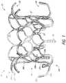
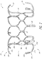
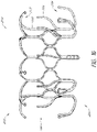
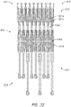
- FIG. 1-5 illustrate a prosthesis 10 in an expanded configuration which can be configured as replacement heart valve.
- the prosthesis 10 can be a replacement heart valve having features similar to those disclosed in U.S. Publication Nos. 2014/0277422 , 2014/0277427 , 2014/0277390 , 2015/0328000 . This is inclusive of the entire disclosure and is not in any way limited to the disclosure of the replacement heart valve.
- the prosthesis 10 can include a frame 20 that can be self-expanding or balloon expandable.
- the frame 20 can have a first end 22 , a second end 24 , a middle or intermediate portion 26 , a first anchoring feature 32 and a second anchoring feature 34 .
- the frame 20 may be oriented such that the first end 22 is a proximal end, the second end 24 is a distal end, the first anchoring feature 32 is a proximal anchoring feature and the second anchoring portion 34 is a distal anchoring feature.
- anchoring features 32 , 34 can contact or engage a native valve annulus, such as the native mitral valve annulus, tissue beyond the native valve annulus, native leaflets, and/or other tissue at or around the implantation location. While the anchoring features 32 , 34 have been illustrated as extending from the first and second ends 22 , 24 of the frame 20 respectively, it should be understood that the anchoring features 32 , 34 can be positioned along any other portion of the frame 20 as desired. Moreover, while two anchoring features 32 , 34 have been included in the illustrated embodiment, it is contemplated that fewer or greater sets of anchoring features can be utilized.
- the frame 20 can include a number of struts with at least some of the struts forming cells 36a and 36b.
- the struts may be arranged so that they are parallel or generally or substantially parallel to a longitudinal axis of the frame 20 .
- the longitudinal axis of the frame 20 may be defined as the central axis that extends through the center of the frame 20 between the first and second ends 22 , 24 of the frame 20 .
- One or more struts 38 can include eyelets. As illustrated, a plurality of eyelets are located along the strut 38 and extend along a single row. As will be described below, the eyelets may be used to attach features such as the valve 40 , liner 50 , and/or flap or sail assembly 60 to the frame 20 .
- the struts 38 having eyelets can extend from a distal-most end of the cells 36b in a direction parallel with the longitudinal axis of the frame, although it is also contemplated that the struts 38 can extend from other portions of the frame 20 such as the interconnecting regions 37 between the cells 36a , 36b , the proximal-most end of the cells 36a , 36b , or any other portion as desired such as apices, junctions, other parts of struts, etc.
- FIG. 1 and 2 includes two rows of cells 36a , 36b.
- the two rows of cells 36a , 36b can include an interconnecting region 37 between each cell 36a , 36b .
- the interconnecting region 37 can include a laterally extending structure between two adjacent cells 36a, 36b to increase separation distance. This can allow the cells 36a, 36b to more easily deform thereby facilitating the transition from the collapsed configuration to the expanded configuration.
- cells 36a, 36b there can be two rows of nine cells 36a, 36b with the first row of cells 36a positioned closer to the first end 22 of the frame 20 and the second row positioned closer to the second end 24 of the frame 20 .
- the cells 36b in the second row can share struts from the cells 36a of the first row.
- the cells 36b in the second row can have a different shape from the cells 36a of the first row.
- cells 36a When in the expanded configuration, cells 36a can have two longitudinally extending sides with the lower end having a pointed onion-shape.
- the upper end, which can form part of the first anchoring feature 32 can have a pointed onion-shape similar to the lower end.
- cells 36b When in the expanded configuration, cells 36b can have a generally elliptical shape with pointed, outwardly extending ends along the upper and lower sections such that cells 36b resemble an onion.
- the cells 36c can be formed between two struts having a compressed "bell curve" shape.
- Cells 36a can be larger than cells 36b .
- the cells 36b of the second row can have the same shape as the cells 36a of the first row. While each of the cells 36a, 36b are shown having the same shape as other cells 36a, 36b, of the same row, it is contemplated that the shapes of cells 36a, 36b, within a row can differ.
- a portion of the frame 20 can extend radially outward from the longitudinal axis of the frame 20 .
- the cells 36a can create a flared or shoulder portion 28 of the frame 20 .
- This flared or shoulder portion 28 can form part of the first anchoring feature 32 of the prosthesis 10 .
- a portion of the frame 20 such as the cells 36a , can extend radially outward via a bend beginning at or proximate the ends the struts forming the longitudinally extending sides of cells 36a .
- the radius of curvature of this bend can be relatively constant throughout the length of the bend or can differ along the length of the bend.
- the radius of curvature may increase from the beginning of the bend towards the end of the bend, such as ends 39a of cells 36a , or may decrease from the beginning of the bend towards the ends of the bend, such as ends 39a of cells 36a .
- the ends 39a of cells 36a can extend radially outward from the longitudinal axis of the frame 20 in a direction generally perpendicular to the longitudinal axis.
- the frame 20 can include a second bend, after the first bend, which extends the frame in an different direction from the first bend.
- the second bend can cause a portion of the frame 20 , such as cells 36a , to curve radially inward towards the longitudinal axis of the frame 20 .
- the ends 39a of cells 36a can extend in a direction generally parallel to the longitudinal axis or further radially inward. A greater number of bends may also be incorporated.
- the ends 39a of cells 36a extend in a direction which forms an acute angle relative to a perpendicular line passing through the longitudinal axis of the frame 20 .
- the angle can be between about 0 degrees and about 30 degrees, between about 5 degrees and about 25 degrees, between about 10 degrees and about 20 degrees, any sub-range within these ranges, or any other angle as desired.
- the ends 39a of cells 36a can be at or proximate the upper-most portion of the frame 20 .
- the ends 39a of the cells 36a can also extend towards the second end 24 of the frame 20 .
- the second row of cells 36b can extend in a direction generally parallel to the longitudinal axis of the frame 20 .
- the ends 39b of the cells 36b can extend in a direction generally parallel to the longitudinal axis of the frame 20 .
- the bend formed along a portion of the frame 20 can generally form an arc with an angle between about 90 degrees to about 180 degrees such that, at the end of the bend, the frame 20 extends in a direction radially outward from a longitudinal axis of the frame 20 and towards the second end 24 of the frame 20 .
- the arc can have an angle of about 110 degrees.
- the bend of cells 36a can form an arc with an angle between about 0 degrees to about 90 degrees such that, at the end of the bend, the frame 20 extends in a direction radially outward from a longitudinal axis of the frame 20 and upwards.
- the bend of cells 36a can form an arc with an angle between about 180 degrees to about 270 degrees such that, at the end of the bend, the frame 20 extends in a direction radially inward towards a longitudinal axis of the frame 20 and towards a second end 24 of the frame 20 .
- the bend of cells 36a can form an arc with an angle between about 270 degrees to about 360 degrees such that, at the end of the bend, the frame 20 extends in a direction radially inward towards a longitudinal axis of the frame 20 and upwards.
- the radius of curvature of the arc may be constant such that the bend forms a circular arc or may differ along the length of the bend.
- the frame 20 can incorporate additional bends after the initial bend. Such bends can incorporate the structural features described above.
- the frame 20 can include a first bend forming an arc with an angle between about 60 degrees to about 100 degrees and a second bend, in an opposite direction, which forms an arc with an angle between about 90 degrees to about 180 degrees.
- the cells 36b can be generally parallel with the longitudinal axis of the frame 20 . In this manner, the cells 36b can create a cylindrical portion of the frame 20 . In some embodiments, the valve 40 (as shown in Figure 3 ) can be positioned within the cylindrical portion. Although the frame 20 has been described as having two rows of nine cells 36a, 36b each, any number of rows can be used and any number of cells may be contained in the rows. In some embodiments, the number of cells can correspond to the number of anchors forming the first anchoring feature 32 , the number of anchors forming the second anchoring feature 34 and/or struts having eyelets 38 .
- Cells 36a, 36b can allow the frame 20 to foreshorten.
- Foreshortening of the frame 20 can be used to secure the prosthesis to intralumenal tissue in a body cavity, for example tissue at or adjacent a native valve, such as a native valve annulus and/or leaflets.
- Opposing anchoring features 32 , 34 can be constructed on the frame 20 so that portions of the anchoring features 32 , 34 , such as the flared or shoulder portion 28 , tips 33 extending from ends 39a , and/or tips 35b extending from anchors 35a , move closer together as the frame 20 foreshortens.
- this can allow the anchoring features 32 , 34 to close in on opposite sides of the native mitral annulus to thereby secure the prosthesis at the mitral valve.
- the anchoring features 32 , 34 can be positioned such that the anchoring features 32 , 34 do not contact the native mitral annulus at the same time.
- the anchoring feature 34 may contact the native mitral annulus while the anchoring feature 32 does not contact the native mitral annulus.
- the anchoring features 32 , 34 can be positioned such that the anchoring features 32 , 34 grasp opposite side of the native mitral annulus.
- the frame 20 can have a cylindrical or slightly cylindrical shape when in the expanded configuration.
- the cylindrical shape can correspond to the cells 36b .
- the middle portion 26 of the frame 20 can be substantially similar in shape and size as the second end 24 of the frame 20 .
- the first end 22 can have a diameter which is greater than the diameter of the middle portion 26 of the frame 20 and/or the second end 24 of the frame 20 .
- the frame 20 can include an outwardly flared portion or shoulder portion 28 at or adjacent the first end 22 of the frame corresponding to the cells 36a .
- the flared or shoulder portion 28 can facilitate blood flow through the prosthesis 10 from the first end 22 of the frame 20 to the second end 24 of the frame 20 .
- the second end 22 of the frame 20 can have a diameter which is the same as or similar to that of the middle portion 26 of the frame 20 although it is contemplated that the second end 24 can have a diameter which is greater than that of the middle portion 26 .
- the second end 24 may include a flared or shoulder portion similar to that of the first end 22 .
- the middle portion 26 can have a diameter which is greater than the diameter of one or both of the first and second ends 22 , 24 of the frame 20 .
- the diameter of the middle portion 26 of the frame 20 can be in the range of about 20mm to about 40mm when expanded, in the range of about 25mm to about 35mm when expanded, in the range of about 28mm to about 32mm when expanded, any other sub-range within these ranges when expanded, or any other diameter when expanded as desired. As shown in the illustrated example, the diameter of the middle portion 26 of the frame 20 can be about 30mm when expanded.
- the diameter of the middle portion 26 of the frame 20 may be chosen such that the middle portion 26 of the frame 20 is adequately spaced from the body cavity when the frame 20 is positioned within the body cavity.
- the middle portion 26 may have a diameter which is less than the diameter of the native mitral valve annulus.
- the diameter of the middle portion 26 can be about 30mm. Accordingly, the diameter of the middle portion 26 may be about 75% of the diameter of the native mitral valve annulus.
- the diameter of the middle portion 26 may be between about 40% to about 90% of the diameter of the native valve annulus, between about 60% to about 85%, of the diameter of the native valve annulus, between about 70% to about 80% of the diameter of the native valve annulus, any other sub-range between these ranges, or any other percentage as desired.
- the diameter of the middle portion 26 of the frame 20 may be chosen such that the middle portion 26 of the frame 20 contacts the body cavity.
- the middle portion 26 may have a diameter which is about equal to the diameter of the native mitral valve annulus.
- the frame 20 can be made of many different materials, but is preferably made from metal.
- the frame 20 can be made from a shape memory material, such as nitinol.
- a wire frame or a metal tube can be used to make the frame.
- the wire frame of a metal tube can be cut or etched to remove all but the desired metal skeleton.
- a metal tube is laser cut in a repeating pattern to form the frame 20 .
- the flat pattern can be cut from a metal tube and then the tube can be bent and expanded to the shape shown in Figures 1 and 2 .
- the frame 20 can further be expanded and/or compressed and/or otherwise worked to have the desired shape or shapes, such as for introduction and implantation.
- the frame 20 has been described and illustrated as having a circular cross-section, it is contemplated to form all or a portion of the frame 20 into a non-circular cross-section such as, but not limited to, a D-shape, an oval or an otherwise ovoid cross-sectional shape.
- first anchoring feature 32 can include a flared or shoulder portion 28 of the frame and can include ends 39a of cells 36a . Ends 39a of cells 36a can form a plurality of anchors in the form of free apices which can be used to facilitate anchoring or stabilization of the frame 20 within the body cavity.
- the first anchoring feature 32 can also include one or more elongate tips 33 .
- the elongate tips 33 can extend from ends 39a of one or more cells 36a forming part of the anchoring feature 32 .
- the second anchoring feature 34 can include one or more individual anchors 35a having tips or ends 35b .
- Each of the anchoring features 32 , 34 can be positioned or extend generally radially outwardly from the frame 20 , such as the middle portion 26 so that the ends 39a of cells 36a , elongate tips 33 , and tips or ends 35b of anchors 35a are generally spaced away or radially outward from the rest of the frame 20 .
- the anchors 35a can include a base 35c located on a side opposite the tips or ends 35b .
- the base 35c can be for example where the anchors 35a begins to extend from or away from the cells 36b .
- the anchoring features can extend to a radial distance from an exterior surface of the middle portion 26 of the frame 20 that is about 130% or more of the expanded diameter of the frame 20 .
- the middle portion 26 of the frame 20 can have a radius of approximately 15mm from a longitudinal axis of the frame 20 and one or both anchoring features 32 , 34 can extend to a radial distance of approximately 20mm from the longitudinal axis of the frame 20 . This can be particularly advantageous when placed in an annulus of a native valve, such as the annulus of a native mitral valve, which has an effective radius of approximately 20mm.
- all of the anchors of the first anchoring feature 32 such as ends 39a and/or elongate tips 33
- all of the anchors of the second anchoring feature 34 such as anchors 35a
- all of the anchors of the first anchoring feature 32 and/or all of the anchors of the second anchoring feature 34 extend at least to this radial distance.
- fewer than all of the anchors of the first anchoring feature 32 and/or all of the anchors of the second anchoring feature 34 extend to this radial distance. Other radial distances are also contemplated.
- the radial distance of ends, such as tips or ends 33 , 35b , 39a of the anchors from a central longitudinal axis passing through the middle of the frame 20 may be about 150% or more, about 180% or more, about 200% or more, about 220% or more, or about 250% or more of the radius of the middle portion 26 of the frame 20 when the frame 20 and the anchors are in expanded configurations.
- the radius of the middle portion 26 of the frame 20 is 15 mm and an anchor end is spaced 5 mm from the exterior of the middle portion 26 of the frame 20
- the anchor extends 20mm from the central longitudinal axis of the frame 20 , and is 133.33% of the radius of the frame 20 .
- the outermost tip diameter may be greater than the frame diameter as described above and may be in the range of about 35mm to about 55mm when expanded, in the range of about 40mm to about 50mm when expanded, in the range of about 40mm to about 45mm when expanded, any sub-range within these ranges when expanded, or any other diameter as desired.
- the cylindrical shape of the frame 20 in combination with the anchoring features 32 , 34 , can advantageously allow the frame 20 to float within a native valve while the anchors engage a native valve annulus or other body cavity and spacing the inlet and outlet of the frame 20 away from the heart or vessel wall. This can help reduce undesired contact between the frame 20 of the prosthesis 10 and the heart or vessel, such as the ventricular wall of the heart or the native valve annulus as described above.
- the first anchoring feature 32 and the second anchoring feature 34 can extend radially outward from the longitudinal axis of the frame 20 to about the same radial dimension.
- the second anchoring feature 34 can be positioned to be not as far radially outward as the first anchoring feature 32 , and the tips 35b of the anchors 35a may be positioned radially inward of the tips 33 or ends 39a of the first anchoring feature 32 .
- Such a configuration may be advantageous in positioning and securing the prosthesis in a mitral valve or other body location.
- the tips 33 or ends 39a of the first anchoring feature 32 can be positioned further radially outward from the frame 20 than the ends of tips 35b of the anchors 35a when the frame 20 and the anchoring features 32 , 34 are in an expanded configuration.
- some of the anchors of the first anchoring feature 32 (and/or second anchoring feature 34 ) may extend to a first radial distance, and other anchors of the first anchoring feature 32 (and/or second anchoring feature 34 ) may extend to a second radial distance, where the first radial distance is greater than the second radial distance.
- the anchors of the second anchoring feature 34 can be circumferentially aligned with respect to the anchors of the first anchoring feature 32 .
- the anchors of the second anchoring feature 34 can be circumferentially staggered meaning that the tips or ends 33 , 39a of the first anchoring feature 32 are not aligned, and are circumferentially in between the tips or ends 35b of the anchors 35a of the second anchoring feature 34 .
- anchoring features 32 , 34 can have various other configurations.
- individual anchors can extend radially outwardly from the frame at an anchor base and terminate at an anchor tip.
- the individual anchors can be connected to the frame at one of many different locations including apices, junctions, other parts of struts, etc.
- the anchors 35a can extend from an end of the cells 36b although it is also contemplated that the anchors 35a can extend from other portions of the frame 20 , such as the interconnecting regions 37 between cells 36a , 36b , the proximal-most end of the cells 36a , 36b, or any other portion as desired.
- the anchors forming the anchoring features 32 , 34 can comprise first, second, third, or more spaced apart bending stages along the length of each anchor.
- the anchors 35a can extend downwardly from the frame 20 in a direction generally parallel to a longitudinal axis of the frame 20 .
- the anchors 35a include a first bending stage 35d in which the anchors 35a extend radially outward from a longitudinal axis of the frame 20 and towards a first end 22 of the frame 20 and a second bending stage 35e in which the anchors 35a further extend towards the first end 22 of the frame 20 in a direction generally parallel with the longitudinal axis of the frame 20 .
- the anchors 35a include a straight segment between the first bending stage 35d and the second bending stage 35e .
- the straight segment is at roughly a 45 degree angle relative to the longitudinal axis of the frame 20. It is contemplated that the straight segment can be at an acute angle relative to the longitudinal axis of the frame 20 . It is also contemplated that the straight segment can be at an angle greater than 45 degrees. In some embodiments, the angle can be between about 10 degrees to about 70 degrees, between about 20 degrees to about 60 degrees, between about 30 degrees to about 50 degrees, any sub-range within these ranges, or any other angle as desired. In some embodiments, the anchors 35a may extend generally perpendicular to the longitudinal axis of the frame 20 .
- the anchors can also extend either distally or proximally before and/or after one or more of the bending stages. A portion of the anchor may extend with the frame before or after any bending stages. As shown, the anchors 35a can include loops as described above, having a curved or arcuate atraumatic tip to minimize damage to body tissue. Ends of the first anchoring feature 32 can also comprise loops. Further details that may be incorporated and/or interchanged with the features described herein are disclosed in U.S. Publication Nos. 2014/0277422 , 2014/0277427 , 2014/0277390 , 2015/0328000 .
- the elongate tips 33 can extend from an end 39a of the cells 36a .
- the elongate tips 33 can be curved and follow the general curvature of the cell 36a .
- the elongate tips 33 continue the curve of the cells 36a .
- the radius of curvature of the elongate tips 33 can be relatively constant throughout the length of the tip 33 or can differ along the length of the tip 33 .
- the radius may increase from the beginning of the tip 33 towards the end of the tip 33 or may decrease from the beginning of the tip 33 towards the end of the tip 33.
- the elongate tips 33 can be relatively straight.
- the elongate tips 33 can be curved in a different direction from the ends 39a of cells 36a .
- the elongate tips 33 can extend in a direction which forms an acute angle relative to a perpendicular line passing through the longitudinal axis of the frame 20 .
- the angle can be between about 0 degrees and about 60 degrees, between about 15 degrees and about 50 degrees, between about 30 degrees and about 45 degrees, any sub-range within these ranges, or any other angle as desired.
- the prosthesis 10 can have a first anchoring feature 32 with nine anchors, a second anchoring feature 34 with six anchors 35a , and struts 38 having eyelets positioned between every two anchors 35a .
- the struts 38 having eyelets can be circumferentially aligned with ends 39a and/or elongate tips 33 .
- the number of struts 38 having eyelets can correspond to the total number of commissures of the valve 40 .
- the struts 38 of the illustrated example extend below a bottom-most portion of the second anchoring feature 34
- the struts 38 can extend such that they are generally aligned or proximate a bottom-most portion of the second anchoring feature 34 or above a bottom-most portion of the second anchoring feature 34 .
- the struts 38 may extend even further below a bottom-most portion of the second anchoring feature 34 .
- the additional spacing between the anchors 35a can facilitate compression of the frame 20 into a smaller form factor thereby allowing the frame 20 to fit within a smaller delivery device.
- Any number of anchors can be included in first and second anchoring features 32 , 34 .
- the struts 38 having eyelets can be positioned between every other anchor 35a . Moreover, such struts 38 can be positioned between anchors of the first anchoring feature 32 .
- the tips or ends 33 , 35b , 39a as described above can advantageously provide atraumatic surfaces that may be used to grasp intralumenal tissue without causing unnecessary or undesired trauma to tissue.
- the tips or ends 33 , 35b , 39a can form flat, substantially flat, curved or other non-sharp surfaces to allow the tips to engage and/or grasp tissue, without necessarily piercing or puncturing through tissue.
- a looped end or looped anchor may assist the frame in not getting caught up on structures at or near the treatment location.
- each loop can be configured so that when the frame 20 is deployed in-situ and the anchoring features 32 , 34 expand away from the frame 20 , the movement of each loop from a delivered position to a deployed position avoids getting caught on the papillary muscles.
- second anchoring feature 34 include anchors 35a having looped ends with a flattened or rounded top surface.
- the ends of tips 33 can be enlarged relative to other portions of the tips 33 .
- the ends of tips 33 can have a generally "mushroom" shape. Tips 33 can be used to engage a locking mechanism of a delivery system for the prosthesis.
- some of anchors of the first and/or second anchoring features 32 , 34 may have different lengths.
- one or more of the anchors of the second anchoring feature 34 may be a first length and one or more anchors of the second anchoring feature 34 may be a second length.
- the second length may be longer than the first length.
- the anchors having a first length can be deployed or flipped first with the anchors having a second length being deployed or flipped second. This can allow some of the anchors to be deployed to confirm positioning of the prosthesis 10 relative to the body cavity prior to deploying additional anchors. This can also apply to anchors of the first anchoring feature 32 .
- elongate tips 33 can have different lengths.
- the frame 20 itself may be made relatively smaller, which also helps facilitate a lower profile for the prosthesis helpful for delivery and implantation.
- having a prosthesis 10 that can "float" within a native annulus may be usable for a wider variety of patient anatomies, as one or a fewer number of radial sizes of the frames can be used to fit a greater number of patients.
- the anchoring features 32 , 34 are configured to extend further from the frame 20 , these prostheses 10 are still able to securely grasp native tissue as the anchors can expand to different diameters depending on how they are constrained with a body cavity.
- the frame (and the associated valve) may have the same size across multiple patient sizes, and the anchors can either be configured to expand to different diameters, or different anchor arrangements may be used for different frames.
- the prosthesis 10 can include a valve 40 .
- the valve 40 can be positioned within the frame 20 and can be a replacement heart valve which includes a plurality of valve leaflets 42 .
- the valve leaflets 42 can include a first edge 44 , second edge 46 , and tabs 48 for attaching the valve leaflets 42 to struts 38 of the frame 20 such as the struts having eyelets 38 (as shown in Figure 1 ).
- the second edge 46 can be a freely moving edge which can allow the valve 40 to open and close.
- the second edge 46 can extend below a bottom-most portion of the second anchoring feature 34 although it is contemplated that the second edge 46 can be positioned at or proximate the bottom-most portion of the second anchoring feature 34 and/or may be positioned above the bottom-most portion of the second anchoring feature 34 .
- the plurality of valve leaflets 42 can function in a manner similar to the native mitral valve, or to any other valves in the vascular system as desired.
- the plurality of valve leaflets 42 can open in a first position and then engage one another to close the valve in a second position.
- the plurality of valve leaflets 42 can be made to function as a one way valve such that flow in one direction opens the valve and flow in a second direction opposite the first direction closes the valve.
- the valve 40 can open allow blood to flow through the valve 40 in a direction from the first end 22 to the second end 24 (e.g., from a proximal end to a distal end).
- the valve 40 can close to inhibit blood flow through the valve 40 in a direction from the second end 24 to the first end 22 (e.g., from a distal end to a proximal end).
- the valve 40 can be constructed so as to open naturally with the beating of the heart.
- the plurality of valve leaflets 42 can open during diastole and close during systole.
- the valve 40 can replace a damaged or diseased native heart valve such as a diseased native mitral valve.
- the valve 40 can include a liner 50 .
- the liner 50 can be used to assist with fluid flowthrough and/or around the valve prosthesis 10 , such as through and around the frame 20 and the valve leaflets 42 .
- the liner 50 can surround at least a portion of the valve leaflets 42 and be connected to one or more of the valve leaflets 42 .
- the one or more valve leaflets 42 can be attached to the liner 50 along the first edge 44 of the valve leaflets 42 .
- the liner 50 can be positioned within the interior of the frame 20 and can form an inner wall of the prosthesis 10 .
- the liner 50 can be positioned such that the liner 50 is radially inward, relative to the longitudinal axis of the frame 20 , from the struts of the frame 20 .
- the fluid pathway towards the valve leaflets 42 can be relatively smooth.
- the liner 50 can at least be partially positioned along an exterior of the frame 20 such that at least a portion of the liner 50 is radially outward, relative to the longitudinal axis of the frame 20 , from struts of the frame 20 .
- the liner 50 can be positioned along an inlet side of the prosthesis 10 .
- the liner 50 can extend from the first edge 44 of the valve leaflets 42 towards the first end 22 of the frame 20 .
- the liner 50 can also extend below the first edge 44 of the valve leaflet 42 towards the second end 24 of the frame 20.
- the liner 50 can also be made to move with foreshortening portions of the frame 20.
- the liner 50 can extend the entire length of the frame 20 or it can extend along only part of the length of the frame 20 as shown.
- the ends of the valve leaflets 42 can coincide with ends of the liner 50 .
- one or more of the ends of the frame 20 can coincide with the ends of the liner 50 .
- an end 52 of the liner 50 can be positioned between the first end 22 of the frame 20 and the valve leaflets 42 .
- the end 52 of the liner 50 can extend to the first end 22 of the frame 20 and can also extend over the first end 22 .
- the liner 50 can extend at least partially over the first anchoring feature 32 .
- the liner 50 may extend along the length of the leaflets, but is not connected to them.
- the liner 50 is attached to the frame 20 and the leaflets 42 are attached to the liner 50 .
- the valve leaflets 42 can also be attached to the frame 20 .
- the liner 50 and/or the valve leaflets 42 can be attached to the frame 20 or to each other using any mechanism or technique as desired such as, but not limited to, mechanical fasteners, such as sutures, staples, screws, rivets, and any other type of mechanical fastener as desired, chemical fasteners such as adhesives and any other type of chemical fastener as desired, fastening techniques such as welding, sintering, and any other type of fastening technique as desired, and/or a combination of such fasteners and techniques.
- mechanical fasteners such as sutures, staples, screws, rivets, and any other type of mechanical fastener as desired
- chemical fasteners such as adhesives and any other type of chemical fastener as desired
- fastening techniques such as welding, sintering, and any other type of fastening technique as desired, and/or a combination of such fasteners and techniques.
- the liner 50 can be constructed in multiple different ways.
- the liner 50 can be made a layer of resilient material, such as such as knit polyester (e.g., polyethylene terephthalate (PET)) or any other biocompatible material such as those which are wholly or substantially fluid impermeable, flexible, stretchable, deformable, and/or resilient.
- the liner 50 can be made from a material that is more flexible than the valve leaflet material.
- the distal and/or proximal end, such as end 52 , of the liner 50 can be straight, curved, or have any other desired configuration.
- the liner 50 can have a straight edge forming the end 52 .
- the end 52 can be patterned to generally correspond to the undulations at one end of the frame 20 .
- the liner 50 can be formed of one piece or multiple pieces.
- the liner 50 attached to the valve leaflets 42 can be one piece and one or more anchors, such as first anchoring feature 32 , can be covered by a separate piece of material of the liner 50 .
- anchors of the first anchoring feature 32 may be covered as noted above, or only a portion may be covered.
- the end can extend past the frame 20 and can be wrapped around it.
- the liner 50 can extend from the inside of the frame 20 to the outside of the frame 20 .
- the liner 50 can extend completely around the frame 20 for 1/4, 1/3, 1/2, or more of the length of frame 20.
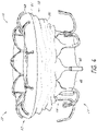
- the prosthesis 10 can include a flap or sail assembly 60 which can be positioned around and secured to an exterior of the frame 20 .
- the flap assembly 60 can be annular and can extend entirely circumferentially around the frame 20 .
- the flap assembly 60 can prevent or inhibit backflow of fluids around the prosthesis 10 .
- the flap assembly 60 can create an axial barrier to fluid flow exterior to the frame 20 when deployed within a body cavity.
- the flap assembly 60 can form a flange 66 when the flap assembly 60 is positioned within a body cavity, such as a native valve, with the flange 66 sealing against at least a portion of tissue surrounding the body cavity.
- the flap assembly 60 can encourage tissue in-growth between the flap assembly 60 and the natural tissue. This may further help to prevent leakage of blood flow around the prosthesis 10 .
- the flap assembly 60 can have a first end 62 positioned at or proximate a first end 22 of the frame 20 and extend to a second end 64 positioned at or proximate a second end 24 of the frame 20 .
- the second end 64 of the flap assembly 60 can be provided with a generally straight edge with extends circumferentially around the frame 20 . It is also contemplated that other configurations, such as a curved edge, can also be used as desired.
- the second end 64 can follow the shape of the struts along the second end 24 of the frame 20 .
- the flap assembly 60 can form a flange 66 .
- the flange 66 can extend generally radially outward in a direction generally orthogonal to the longitudinal axis of the frame 20 .
- the flange 66 can also project towards the first end 22 and/or second end 24 of the frame 20 .
- the flange 66 can be used to further prevent or inhibit backflow of fluids around the prosthesis 10 .
- the flange 66 can be formed when the flap assembly 60 is positioned within the body cavity, such as a native valve 80 .
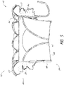
- the flap assembly 60 can include a first portion 68 which extends radially outward from the frame 20 and a second portion 70 which extends from the first portion 68 in a direction generally towards an opposing end of the frame 20 .
- the first portion 68 can extend along an exterior portion of the frame 20 as shown.
- the first portion 68 can extend along the flared or shoulder portion 28 of the frame 20 .
- the first portion 68 can follow a curvature of the frame 20 and can form a funnel which assists in directing fluid flow through an interior of the frame 20 where fluid can pass through the valve 40 .
- the first portion 68 can be attached to the end 52 of the liner 50 at a first end of the first portion 68 using any mechanism or technique as described above, such as via sutures and/or adhesives.
- the first portion 68 can extend up to or proximate the elongate tips 33 although it is contemplated that the first portion 68 can extend only partially towards the elongate tips 33 or can extend beyond the elongate tips 33 .
- the second portion 70 can extend from the first portion 68 towards an opposing end of the frame 20 .
- the second portion 70 can extend from the first portion 68 at or proximate the first end 22 of the frame 20 and extend towards the second end 24 of the frame 20 .
- the second portion 70 extends up to or proximate the second end 24 of the frame 24 although it is also contemplated that the second portion 70 can extend only partially towards the second end 24 or can extend beyond the second end 24 .
- the second portion 70 can extend up to an intermediate portion of the frame 20 between the first end 22 and the second end 24 of the frame 20 .
- the second portion 70 can extend beyond or over the second end 24 of the frame 20 .
- the second portion 70 can extend along and/or over a portion of the second anchoring feature 34 . As shown in the illustrated example, fluid can flow around the flap 60 and into the space 74 formed between the liner 50 , first portion 68 , and the second portion 70 .
- the first portion 68 and/or the second portion 70 can be formed from a material such as such as knit polyester (e.g., polyethylene terephthalate (PET)) or any other biocompatible material such as those which are wholly or substantially fluid impermeable, flexible, stretchable, deformable, and/or resilient.
- the first portion 68 , second portion 70 , and/or the liner 50 may be made from the same or similar materials.
- the first portion 68 and the second portion 70 can be formed as separate components and can be attached together using any mechanism or technique as described above, such as via sutures and/or adhesives. In other embodiments, the first portion 68 and second portion 70 can be a single component.
- the flap assembly 60 may be attached to the frame 20 using similar mechanisms and/or techniques.
- the first end 62 and the second end 64 of the flap assembly 60 can be attached to struts and/or anchoring features 32 , 34 of the frame 20 via sutures.
- the flap assembly 60 can also include other structures, such as wires formed from resilient materials such as nitinol, to allow at least portions of the flap assembly 60 to retain a particular shape. These structures may be positioned on an inner surface of the flap assembly 60 .
- the flap assembly 60 can be attached to the frame 20 , the first anchoring feature 32 , and/or the second anchoring feature 34 in many different ways.
- the flap assembly 60 can be sewn to the frame 20 , the valve 40 , and/or the liner 50 .
- the first portion 68 is attached to the first anchoring feature 32 and the second portion 70 is attached to the struts of frame 20 using sutures.
- the flap assembly 60 is only attached to the frame 20 along the second end 64 of the flap assembly 60 , and the first portion 68 remains unattached to any portion of the frame 20 or any anchoring features 32 , 34 .
- a plurality of circumferentially spaced tabs 76 can be used to attach the flap assembly 60 to portions of the anchors of the second anchoring feature 34 .
- the tabs can be wrapped around the anchors.
- the tabs 76 themselves may also form sleeves that are configured to surround at least a portion of the anchors.
- the anchors such as anchor of anchoring features 32 , 34 , can include eyelets that may be used to secure the flap assembly 60 to the anchor.
- the tab 76 can be attached to the eyelet using any mechanism or technique described above, for example by stitching.
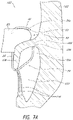
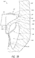
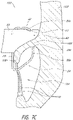
- FIGS 7A-9 illustrate schematic representations of an example of the prosthesis 10 positioned within a native mitral valve of a heart 100 .
- a portion of the native mitral valve is shown schematically and represents typical anatomy, including a left atrium 102 positioned above an annulus 106 and a left ventricle 104 positioned below the annulus 106 .
- the left atrium 102 and left ventricle 104 communicate with one another through a mitral annulus 106 .
- Also shown schematically in Figures 7A-9 is a native mitral leaflet 108 having chordae tendineae 110 that connect a downstream end of the mitral leaflet 108 to the papillary muscle of the left ventricle 104 .
- the portion of the prosthesis 10 disposed upstream of the annulus 106 can be referred to as being positioned supra-annularly.
- the portion generally within the annulus 106 is referred to as positioned intra-annularly.
- the portion downstream of the annulus 106 is referred to as being positioned sub-annularly (toward the left ventricle). While the mitral leaflet 108 is illustrated in a relatively unwrinkled state, it should be understood that the mitral leaflet 108 may be in a relatively wrinkled state such as is shown in Figures 11 , 12 and 14 .
- the replacement heart valve 10 can be disposed so that the mitral annulus 106 is between the first anchoring feature 32 and the second anchoring feature 34 .
- the prosthesis 10 can be positioned such that ends or tips 35b of the anchors 35a contact the annulus 106 as shown, for example, in Figures 7A-7C .
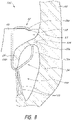
- the prosthesis 10 can be positioned such that ends or tips 35b of the anchors 35a do not contact the annulus 106 as shown, for example, in Figure 8A .
- the prosthesis 10 can be positioned such that the portions of the second anchoring feature 34a , such as one or more anchors 35b , do not extend around the leaflet 108 as shown in Figure 9 . While Figures 7A-9 are described separately below, it should be understood that one or more of the situations illustrated in 7A-9 may be present when the prosthesis 10 is positioned at the implantation location, such as a native mitral valve. For example, in some situations the prosthesis 10 may be positioned such that some portions of the first anchoring feature 32 may contact the annulus 106 while other portions of the first anchoring feature 32 may not and/or such that some portions of the second anchoring feature 34 may contact the annulus 106 while other portions of the second anchoring feature 34 may not.
- the prosthesis 10 can be positioned so that the ends or tips 35b of the anchors 35a of the second anchoring feature 34 are on a ventricular side of the mitral annulus 106 and the ends or tips 33 , 39a of the first anchoring feature 32 are on an atrial side of the mitral annulus 106 .
- the distal anchors 30 can be positioned such that the ends or tips 32 of the distal anchors 30 are on a ventricular side of the native leaflets beyond a location where chordae tendineae 110 connect to free ends of the native leaflets.
- the anchors 35a may extend between at least some of the chordae tendineae 110 and, in some situations such as those shown in Figures 7A-7C , can contact or engage a ventricular side of the annulus 106. It is also contemplated that in some situations, such as those shown in Figure 8 , the anchor 35a may not contact the annulus 106 , though the anchors 35b may still contact the native leaflet 108 . In some situations, the anchors 35a can contact tissue of the left ventricle 104 beyond the annulus 106 and/or a ventricular side of the leaflets.
- the anchors 35a (along with the frame 20 ) can be moved toward the ventricular side of the annulus 106 with the anchors 35a extending between at least some of the chordae tendineae 110 to provide tension on the chordae tendineae 110 .
- the degree of tension provided on the chordae tendineae 110 can differ. For example, little to no tension may be present in the chordae tendineae 110 as shown in Figure 7C where the leaflet 108 is shorter than or similar in size to the anchors 35a .
- a greater degree of tension may be present in the chordae tendineae 110 as shown in Figures 7A and 7B where the leaflet 108 is longer than the anchors 35a and, as such, takes on a compacted form and is pulled proximally.
- An even greater degree of tension may be present in the chordae tendineae 110 as shown in Figure 8 where the leaflets 108 are even longer relative to the anchors 35a .
- the leaflet 108 is sufficiently long such that the anchors 35a do not contact the annulus 106 .
- the first anchoring feature 32 can be positioned such that the ends or tips 33, 39a of the first anchoring feature 32 are adjacent the atrial side of the annulus 106 and/or tissue of the left atrium 102 beyond the annulus 106 . In some situations, some or all anchors of the first anchoring feature 32 may only occasionally contact or engage the atrial side of the annulus 106 and/or tissue of the left atrium 102 beyond the annulus 106 . For example, as shown in Figures 7A and 7B , the first anchoring feature 32 may be spaced from the atrial side of the annulus 106 and/or tissue of the left atrium 102 beyond the annulus 106 . The first anchoring feature 32 could provide axial stability for the prosthesis 10 .
- first anchors of the first anchoring feature 32 may contact the flap assembly 60 . In some situations, it is contemplated that some or all of first anchoring feature 32 may not contact the flap assembly 60 . This may occur when the flap assembly 60 is in a collapsed configuration although it may also occur when the flap assembly 60 is in an expanded configuration. It is also contemplated that some or all of the first anchoring feature 32 may contact the atrial side of the annulus 106 and/or tissue of the left atrium 102 beyond the annulus 106
- the flap assembly 60 can be positioned such that the first end 62 of the flap assembly 60 is positioned along or adjacent an atrial side of the annulus 106.
- the first end 62 can be positioned between the atrial side of the annulus 106 and the first anchoring feature 32 .
- the first end 62 can extend radially outward such that the flap assembly 60 is positioned along or adjacent tissue of the left atrium 102 beyond the annulus 106 .
- the flap assembly 60 can create a seal over the atrial side of the annulus 106 when the flap assembly 60 is in an expanded state.
- the flap assembly 60 may also create a seal over the atrial side of the annulus 106 when the flap assembly is in a collapsed state.
- the flap assembly 60 can transition from the collapsed state to the expanded state during systole when pressure in the left ventricle 104 increases. This increased pressure within the left ventricle 104 can cause blood within the left ventricle 104 to be directed to areas of lower pressure, such as the aorta (not shown) and the left atrium 102 . As noted above, during systole the valve 40 may be closed to prevent blood from flowing back into the left atrium 102 . A substantial portion of blood can forced around the frame 20 and valve 40 and into the flap assembly 60 such that the flap assembly 60 can expand. Sealing along an atrial side of the annulus 106 can be particularly effective.
- the left atrium 102 can be at a lower pressure in comparison to the pressure of the space 74 between the flap assembly 60 and the valve 40 , which is closer to the pressure of the left ventricle 104 .
- the existence of such a pressure differential between the left atrium 102 and the space 74 during systole can allow the flap assembly 60 to apply a greater force to surrounding tissue within the left atrium 102 .
- the flap assembly 60 can transition from the expanded state back to the collapsed state.
- the flap assembly 60 may not contact the wall of the heart 100 . This may occur when the flap assembly 60 is in a collapsed configuration although it may also occur when the flap assembly 60 is in an expanded configuration. In some situations such as those shown in Figures 7B and 7C , the flap assembly 60 may contact the wall of the heart 100 . This may occur when the flap assembly 60 is in an expanded configuration although it may also occur when the flap 60 is in a collapsed configuration. As shown in Figures 7A-8 , the flap assembly 60 can also assist in filling gaps which exist between the leaflet 108 and the frame 20 (portions of which are illustrated in dashed lines).
- the leaflet 108 may not be captured between the frame 20 (portions of which are shown in dashed lines) and the one or more anchors of the second anchoring feature 34 .
- the anchor 35a may be positioned along an atrial surface of the leaflet 108 .
- the anchor 35a may also be positioned along an inner surface of the annulus 106 . It is also contemplated that the anchor 35a may exert a force against the leaflet 108 such that the leaflet 108 is pushed radially outward, relative to the longitudinal axis of the frame 20 , towards a wall of the heart 100.
- the flap assembly 60 can create a seal intra-annularly and/or along an atrial side of the leaflet 108 .
- the flap assembly 60 can create a seal along a ventricular side of the annulus 106 .
- the prosthesis 10 may be disposed in the mitral annulus such that a portion of the flap assembly 60 is positioned on the ventricular side of the native annulus 106.
- the in vivo situations of Figure 7A-9 have been described separately, it should be understood that one or more of these situations may be present when a prosthesis is positioned at the implantation location, such as a native mitral valve.
- a prosthesis is positioned at the implantation location, such as a native mitral valve.
- the anchors of the second anchoring feature 34 may not capture the leaflet 108 whereas the remaining anchors 30 of the second anchoring feature 34 may capture the leaflet 108 .
- the flap assembly 60 can contact the wall of the heart 100 along one or more portions of an outermost circumference of the first end 62 and may not contact the wall of the heart 100 along other portions of the outermost circumference of the first end 62 .
- the flap assembly 60 may contact the wall of the heart 100 along an approximately 180 degree portion of the outermost circumference of the first end 62 and may not contact the wall of the heart 100 along the remaining, approximately 180 degree portion of the outermost circumference of the first end 62 .
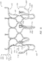
- Prosthesis 210 can have a similar construction to prosthesis 10 .
- Prosthesis 210 can include arms 221 positioned along the frame 220 between the first end 222 and the second end 224 .
- the arms 221 can extend radially outward from the longitudinal axis of the frame 220 when the frame 220 is in an expanded configuration.
- the arms 221 can extend from the frame 220 in a direction towards the first end 222 of the frame 220 .
- the arms 221 can contact a flap assembly, such as flap assembly 260 , to bias the flap assembly towards an inflated or expanded configuration even in the absence of fluid within the flap assembly.
- the arms 221 can support the flap assembly 260 and reduce the likelihood of deflation or collapse during the diastolic cycle.
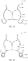
- FIG. 11 illustrates a schematic representation of an embodiment of the prosthesis 210 having an flap assembly 260 positioned within a native mitral valve of a heart 100 .
- arms 221 can contact the flap assembly 260 along the second portion 270 of the flap assembly 260 .
- the flap assembly 260 can be biased towards the inflated configuration via both the arms 221 and the first anchoring feature 232 to which the flap assembly 260 can be attached.
- the radial distance of arms 221 from the longitudinal axis of the frame 220 can be chosen such that the flap assembly 260 is placed at or proximate tissue of the body cavity.
- the radius of the arms 221 can be chosen such that the flap assembly 260 contacts or is proximate the leaflets 108 of the mitral valve. While the mitral leaflet 108 is illustrated in a relatively wrinkled state, it should be understood that the mitral leaflet 108 may be in a relatively unwrinkled state such as is shown in Figures 7A-9 .
- the radial distance of arms 221 from the longitudinal axis passing through the middle of the frame 220 may be about 110% or more, about 120% or more, about 130% or more, about 140% or more, or about 150% or more of the radius of the middle portion 226 of the frame 220 when the frame 220 and the anchoring features 232 , 234 are in expanded configurations.
- the radius of the middle portion 226 of the frame 220 is 15 mm and an arm 221 is spaced 5 mm from the exterior of the middle portion 226 of the frame 220
- the arm 221 extends 20mm from the longitudinal axis of the frame 220 , and is 133.33% of the radius of the frame 220 .
- the arms 221 can be bent inwardly towards the frame 220 when the frame 220 is in a collapsed configuration.
- Figures 10 and 11 include an arm 221 positioned within the interior of the flap assembly 260 , it is also contemplated that the arm 221 can be positioned outside of or exterior to the flap assembly 260 .
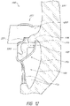
- the arm 221 can be positioned along an exterior surface of the flap assembly 260 as shown in Figure 12 .
- the flap assembly 260 may be attached to the arm 221 using any suitable mechanism or technique described above, such as via sutures. While the mitral leaflet 108 is illustrated in a relatively wrinkled state in Figure 12 , it should be understood that the mitral leaflet 108 may be in a relatively unwrinkled state such as is shown in Figures 7A-9 .
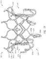
- the prosthesis 310 can have a similar construction to prostheses 10 , 210 .
- Prosthesis 310 can include arms 321 positioned along the frame 320 between the first end 322 and the second end 324 .
- the arms 321 can extend radially outward from the longitudinal axis of the frame 320 when the frame 320 is in an expanded configuration.
- the arms 321 can extend from the frame 320 in a direction towards the second end 324 of the frame 320 .
- the arms 321 can contact a flap assembly, such as flap assembly 360 , to bias the flap assembly towards an inflated or expanded configuration even in the absence of fluid within the flap assembly.
- the arms 321 can support the flap assembly 360 and reduce the likelihood of deflation or collapse during the diastolic cycle.
- FIG 14 illustrates a schematic representation of an embodiment of the prosthesis 310 having an flap assembly 360 positioned within a native mitral valve of a heart 100 .
- arms 321 can contact the flap assembly 360 along the second portion 370 of the flap assembly 360 .
- the flap assembly 360 can be biased towards the inflated configuration via both the arms 321 and the first anchoring feature 332 to which the flap assembly 360 can be attached.
- the radial distance of arms 321 from the longitudinal axis of the frame 320 can be chosen such that the flap assembly 360 is placed at or proximate tissue of the body cavity.
- the radius of the arms 321 can be chosen such that the flap assembly 360 contacts or is proximate the leaflets 108 of the mitral valve. While the mitral leaflet 108 is illustrated in a relatively wrinkled state, it should be understood that the mitral leaflet 108 may be in a relatively unwrinkled state such as is shown in Figures 7A-9 .
- the prosthesis 410 can have a similar construction to prostheses 10 , 210 , 310 .
- Prosthesis 410 can include a frame 420 , the frame 420 having a first end 422 , a second end 424 , a middle or intermediate portion 426 , a first anchoring feature 432 and a second anchoring feature 434 .
- one or both anchoring features 432 , 434 can contact or engage a native valve annulus, such as the native mitral valve annulus, tissue beyond the native valve annulus, native leaflets, and/or other tissue at or around the implantation location.
- the first anchoring feature 432 can be positioned on an atrial side of the native mitral valve annulus and the second anchoring feature 434 can be positioned on a ventricular side of the native mitral valve annulus. While the anchoring features 432 , 434 have been illustrated as extending from the first and second ends 422 , 424 of the frame 420 respectively, it should be understood that the anchoring features 432 , 434 can be positioned along any other portion of the frame 420 as desired. Moreover, while two anchoring features 432 , 434 have been included in the illustrated example, it is contemplated that fewer or greater sets of anchoring features can be utilized.
- One or more struts 438 of the frame 420 can include eyelets. As illustrated, a plurality of eyelets are located along the strut 438 and extend along a single row. Similar to struts 38 , the eyelets may be used to attach features such as a valve 40 , a liner 50 , and/or a flap or sail assembly 60 to the frame 420 . As also shown in the illustrated example, the struts 438 having eyelets can extend from a distal-most end of cells in a direction parallel with the longitudinal axis of the frame 420 , although it is also contemplated that the struts 438 similar to that described above in connection with struts 38 .
- a portion of the frame 420 can extend radially outward from the longitudinal axis of the frame 420 .
- the cells 436a can create a flared or shoulder portion 428 of the frame 420 .
- This flared or shoulder portion 428 can form part of the first anchoring feature 432 of the prosthesis 410 .
- a portion of the frame 420 such as the cells 436a , can extend radially outward via a bend beginning at or proximate the ends the struts forming the longitudinally extending sides of the cells 436a .
- the cells 436a include a first bend 441a in which the cells 436a extend generally perpendicular to the longitudinal axis of the frame 420 and a second bend 441b in which the cells 436a extend upwardly.
- the second bend 441b can be positioned closer to the first end 422 of the frame 420 than the first bend 441a is positioned.
- the radius of curvature of one or both bends 441a , 441b can be relatively constant throughout the length of the bend or can differ along the length of one or both bends.
- the radius of curvature may increase from the beginning of one or both bends 441a , 441b towards the end of one or both bends 441a , 441b or may decrease from the beginning of one or both bends 441a , 441b towards the ends of one or both bends 441a , 441b .
- two bends 441a , 441b are shown in the illustrated example, a greater number of bends may also be incorporated.
- the ends 439a of cells 436a extend in a direction which forms an acute angle relative to a perpendicular line passing through the longitudinal axis of the frame 420 .
- the angle can be between about 0 degrees and about 75 degrees, between about 10 degrees and about 60 degrees, between about 20 degrees and about 45 degrees, any sub-range within these ranges, or any other angle as desired.
- the ends 439a of cells 436a can extend in a direction which forms an obtuse angle relative to a perpendicular line passing through the longitudinal axis of the frame 420 .
- the ends 439a of cells 436a can be at or proximate the upper-most portion of the frame 420 .
- the first bend 441a formed along a portion of the frame 420 can generally form an arc with an angle between about 45 degrees to about 135 degrees such that, at the end of the first bend 441a , the frame 420 extends in a direction radially outward from a longitudinal axis of the frame 420 and can extend in a direction towards the first end 422 of the frame 420 , a direction perpendicular to a longitudinal axis of the frame, or a direction towards the second end 424 of the frame 420 .
- the arc can have an angle of about 90 degrees.
- the first bend 441a of cells 436a can form an arc with an angle between about 0 degrees to about 90 degrees such that, at the end of the first bend 441a , the frame 420 extends in a direction radially outward from a longitudinal axis of the frame 420 and upwards.
- the radius of curvature of the arc may be constant such that the first bend 441a and/or second bend 441b forms a circular arc or may differ along the length of the first bend 441a and/or second bend 441b .
- the frame 420 can include a first bend 441a forming an arc with an angle between about 60 degrees to about 100 degrees and a second bend 441b , in an opposite direction, which forms an arc with an angle between about 30 degrees to about 60 degrees.
- first anchoring feature 432 can include a flared or shoulder portion 428 of the frame 420 and can include ends 439a of cells 436a . Ends 439a of cells 436a can form a plurality of anchors in the form of free apices which can be used to facilitate anchoring or stabilization of the frame 420 within the body cavity.
- the first anchoring feature 432 can also include one or more elongate tips 433 .
- the elongate tips 433 can extend from ends 439a of one or more cells 436a forming part of the anchoring feature 432 .
- the second anchoring feature 434 can include one or more individual anchors, such as anchors 435a , 490a , having tips or ends, such as tips or ends 435b , 490b .
- each of the anchoring features 432 , 434 can be positioned or extend generally radially outwardly from an outer surface of the frame 420 , such as the middle portion 426 so that the ends 439a of cells 436a , elongate tips 433, tips or ends 435b of anchors 435a , and tips or ends 490b of anchors 490a are generally spaced away or radially outward from the rest of the frame 420 .
- the anchors 435a can include a base 435c located on a side opposite the tips or ends 435b .
- the base 435c can be for example where the anchors 435a begins to extend from or away from a second or bottom row of cells 436b .
- the anchors 435a can extend distally away from the frame at base 435c .
- the anchors 490a can include a base 490c located on a side opposite the tips or ends 4 90b .
- the base 490c can be for example where the anchors 490a begin to extend from or away struts 438 .
- the dimensions of some or all of the anchors of the first anchoring feature 432 , such as ends 439a and/or elongate tips 433 , and/or all of the anchors of the second anchoring feature 434 , such as anchors 435a, 490a can be similar to that described above in connection with first anchoring feature 32 and second anchoring feature 34 .
- the anchors forming the anchoring features 432 , 434 can comprise first, second, third, or more spaced apart bending stages along the length of each anchor.
- the first anchoring feature 432 can include a flared or shoulder portion 428 which has a first bend 441a and a second bend 441b .
- the anchors 435a can extend downwardly from the frame 420 in a direction generally parallel to a longitudinal axis of the frame 420 .
- the anchors 435a can include a first bending stage 435d in which the anchors 435a extend radially outward from the longitudinal axis of the frame 420 such that the anchors 435a extend perpendicular to a longitudinal axis of the frame 420 . During the first bending stage 435d , the anchors 435a can continue to bend such that the anchors are oriented towards the first end 422 of the frame 420.
- the anchors 435a can include a second bending stage 435e in which the anchors 435a in which the anchors 435a bend in an opposite direction radially outward from a longitudinal axis of the frame 420 .
- the anchors 435a can include a third bending stage 435f in which the anchors 435a bend in an opposite direction from the second bending stage 435e .
- the anchors 435a can extend generally proximally towards the first end 422 of the frame 420 in a direction generally parallel with the longitudinal axis of the frame 420 .
- the anchors 435a may extend generally perpendicular to the longitudinal axis of the frame 420.
- the anchors can also extend either distally or proximally before and/or after one or more of the bending stages. A portion of the anchor may extend with the frame before or after any bending stages.
- the anchors 435a can include loops as described above, having a curved or arcuate atraumatic tip to minimize damage to body tissue. Ends of the first anchoring feature 432 can also comprise loops.
- Anchors 490a can include similar structural features to those of anchors 435a such as the three bending stages.
- the anchors 490a can include a straight segment between the first bending stage in which the anchors 490a extend radially outward from a longitudinal axis of the frame 420 and the second bending stage in which the anchor 490a bends in an opposite direction from the first bending stage.
- the straight segment can be generally parallel with the longitudinal axis of the frame 420 . It is contemplated that the straight segment can be at an acute angle relative to the longitudinal axis of the frame 420 and may extend radially outward from the frame between the first and second bending stages.
- anchors 435a , 490a can be used for one or both anchors 435a , 490a .
- the ends 435b, 490b of anchors 435a, 490a are generally aligned in the axial direction such that ends 435b, 490b of anchors 435a, 490a are at the same axial location relative to the outer surface of the frame 420 .
- This can be beneficial as it can allow both anchors 435a, 490a to more easily contact the tissue, such as the native mitral valve annulus.
- some anchors, such as anchors 490a can extend further distally than other anchors, such as anchors 435a.
- the anchors 435a (along with the frame 420 ) can be moved toward the ventricular side of an annulus with the anchors 435a extending between at least some of the chordae tendineae to provide tension on the chordae tendineae.
- a proximal portion of the anchors 435a can apply tension to the chordae tendineae.
- the degree of tension provided on the chordae tendineae can differ. In some situations, little to no tension may be present in the chordae tendineae similar to the situation illustrated in Figure 7C .
- a greater degree of tension may be present in the chordae tendineae similar to the situation illustrated in Figures 7A , 7B and 8 .
- the further distal positioning of certain of the anchors, such as anchors 490a can impart a lower degree of tension to the chordae tendineae. This can be particularly beneficial in situations where a patient's chordae tendineae are already subject to a greater degree of tension prior to deployment of the prosthesis 410 within the mitral annulus. Such tension can be due to factors such as an enlarged annulus.
- the prosthesis 410 can be positioned such that ends or tips 435b of the anchors 435a contact the annulus similar to the situation shown in Figures 7A-7C . In some situations, the prosthesis 410 can be positioned such that ends or tips 435b of the anchors 435a do not contact the annulus similar to the situation shown in Figure 8A . In some situations, similar to those illustrated in Figures 7A-7C and 8 , a leaflet of the native valve can be positioned between one or more of the anchors 435a and a portion of the frame 420 and/or the anchors 435a . In some situations, the prosthesis 410 can be positioned such that the portions of the second anchoring feature 434 , such as one or more anchors 435b , do not extend around a leaflet similar to the situation shown in Figure 9 .
- the elongate tips 433 can extend from an end 439a of the cells 436a .
- the elongate tips 433 can be curved and follow the general curvature of the cell 436a .
- the elongate tips 433 continue the curve of the cells 436a and extend generally upwardly.
- the elongate tips 433 can follow the general shape of the wall of the left atrium.
- the radius of curvature of the elongate tips 433 can be relatively constant throughout the length of the tip 433 or can differ along the length of the tip 433 .
- the radius increases towards the end of the tip 433 such that the end of tip 433 includes a generally straight segment extending upwardly.
- the elongate tips 433 can extend generally parallel to the longitudinal axis of the frame 420 .
- the elongate tips 433 can extend in a direction which forms an acute angle relative to the longitudinal axis of the frame 420 .
- the angle can be between about 0 degrees and about 60 degrees, between about 15 degrees and about 50 degrees, between about 30 degrees and about 45 degrees, any sub-range within these ranges, or any other angle as desired.
- the prosthesis 410 can have a first anchoring feature 432 with nine anchors, a second anchoring feature 434 with six anchors 435a extending from bottom apices of a bottom row of cells 436b , and three struts 438 having eyelets positioned between every two anchors 435a and three anchors 490a each extending from a bottom end of the struts 438 .
- Any number of anchors can be included in first and second anchoring features 432 , 434 .
- other ratios such as a 1:1 or a 3:1 correspondence between the anchors, are possible.
- the struts 438 having eyelets can be positioned between every other anchor 435a .
- an anchor 490a can extend from each strut 438 . It is contemplated that anchors 490a can extend from fewer than all struts 438 such that there are fewer anchors 490a than struts 438 . Moreover, such struts 438 can be positioned between anchors of the first anchoring feature 432 .
- the prosthesis 510 can have a similar construction to prostheses 10 , 210 , 310 , 410 .
- Prosthesis 510 can include a frame 520 , the frame 520 having a first end 522 , a second end 524 , a middle or intermediate portion 526 , a first anchoring feature 532 and a second anchoring feature 534 .
- one or both anchoring features 532 , 534 can contact or engage a native valve annulus, such as the native mitral valve annulus, tissue beyond the native valve annulus, native leaflets, and/or other tissue at or around the implantation location.
- anchoring features 532 , 534 have been illustrated as extending from the first and second ends 522 , 524 of the frame 520 respectively, it should be understood that the anchoring features 532 , 534 can be positioned along any other portion of the frame 520 as desired. Moreover, while two anchoring features 532 , 534 have been included in the illustrated example, it is contemplated that fewer or greater sets of anchoring features can be utilized.
- a portion of the frame 520 can extend radially outward via a bend beginning at or proximate the ends the struts forming the longitudinally extending sides of the cells 536a .
- the cells 536a include a first bend 541a in which the cells 536a extend generally perpendicular to the longitudinal axis of the frame 520 and a second bend 541b in which the cells 536a extend upwardly away from a second end 524 of the frame 520 .
- the cells 536a may bend such that they extend radially inward towards the longitudinal axis.
- the radius of curvature of one or both bends 541a , 541b can be relatively constant throughout the length of one or both bends 541a , 541b or can differ along the length of one or both bends 541a , 541b .
- the radius of curvature may increase from the beginning of one or both bends 541a , 541b towards the end of one or both bends 541a , 541b or may decrease from the beginning of one or both bends 541a , 541b towards the ends of one or both bends 541a , 541b.
- two bends 541a , 541b are shown in the illustrated example, a greater number of bends may also be incorporated.
- the ends 539a of cells 536a extend in a direction which forms an obtuse angle relative to a perpendicular line passing through the longitudinal axis of the frame 520 .
- the angle can be between about 90 degrees and about 180 degrees, between about 95 degrees and about 160 degrees, between about 100 degrees and about 140degrees, any sub-range within these ranges, or any other angle as desired.
- the ends 539a of cells 536a can be at or proximate the upper-most portion of the frame 520 .
- the first bend 541a formed along a portion of the frame 520 can generally form an arc with an angle between about 45 degrees to about 135 degrees such that, at the end of the first bend 541a , the frame 520 extends in a direction radially outward from a longitudinal axis of the frame 520 and towards the second end 524 of the frame 520 .
- the arc can have an angle of about 90 degrees.
- the first bend of cells 536a can form an arc with an angle between about 0 degrees to about 90 degrees such that, at the end of the bend, the frame 520 extends in a direction radially outward from a longitudinal axis of the frame 520 and upwards.
- the radius of curvature of the arc may be constant such that the first bend 541a and/or second bend 541b forms a circular arc or may differ along the length of the first bend and/or second bend 541b .
- the frame 520 can include a first bend 541a forming an arc with an angle between about 60 degrees to about 100 degrees and a second bend 541b , in an opposite direction, which forms an arc with an angle between about 90 degrees to about 135 degrees.
- the radially inward bend of the frame 520 can be beneficial in orienting the ends 539a of the cells 536a and the elongate tips 533 away from walls of the heart in which the prosthesis 510 may be positioned. As shown in the illustrated example, the elongate tips 533 can extend radially inwardly towards the longitudinal axis of the frame 520 .
- the elongate tips 533 can extend from an end 539a of the cells 536a .
- the elongate tips 533 can be curved and follow the general curvature of the cell 536a .
- the elongate tips 533 continue the curve of the cells 536a and extend generally radially inwardly towards the longitudinal axis of the frame 520 .
- the radius of curvature of the elongate tips 533 can be relatively constant throughout the length of the tip 533 or can differ along the length of the tip 533 .
- the elongate tips 533 can be generally straight.
- the elongate tips 533 can extend generally radially inward towards the longitudinal axis of the frame 520 .
- the elongate tips 533 can extend in a direction which forms an angle relative to the longitudinal axis of the frame 420 .
- the angle can be between about 0 degrees and about 70 degrees, between about 10 degrees and about 65 degrees, between about 20 degrees and about 60 degrees, any sub-range within these ranges, or any other angle as desired.
- Second anchoring feature 534 can include anchors 535a which can share similar features to the anchors described above, such as anchors 435a .
- Second anchoring feature 534 can include anchors 590a which can extend from a bottom end of the struts 538 having eyelets.
- anchors 590a can extend distally from the frame 520 and include a single bending stage in which the anchor 590a extends radially outward from the longitudinal axis of the frame. During this bending stage, the anchors 590a can continue to bend such that the anchors are oriented towards the first end 522 of the frame 520 .
- the anchors 490a can include a straight segment after the bending stage.
- the straight segment can be generally parallel with the longitudinal axis of the frame 420 . It is contemplated that the straight segment can be at an acute angle relative to the longitudinal axis of the frame 420 and may extend radially outward from the frame between after the bending stage.
- the ends 590b of anchors 590a may not be aligned with ends 535b of anchors 535a .
- the ends 590b may be positioned distal relative to ends 535b .
- the prosthesis 610 can have a similar construction to prostheses 10 , 210 , 310 , 410 , 510 .
- Prosthesis 610 can include a frame 620 , the frame 620 having a first end 622 , a second end 624 , a middle or intermediate portion 626 , a first anchoring feature 632 and a second anchoring feature 634 .
- one or both anchoring features 632 , 634 can contact or engage a native valve annulus, such as the native mitral valve annulus, tissue beyond the native valve annulus, native leaflets, and/or other tissue at or around the implantation location.
- anchoring features 632 , 634 have been illustrated as extending from the first and second ends 622 , 624 of the frame 620 respectively, it should be understood that the anchoring features 632 , 634 can be positioned along any other portion of the frame 620 as desired. Moreover, while two anchoring features 632 , 634 have been included in the illustrated example, it is contemplated that fewer or greater sets of anchoring features can be utilized.
- the first anchoring feature 632 can be similar to the first anchoring feature 532 of prosthesis 510 .
- a portion of the frame 620 can extend radially outward via a first bend and a second bend in which a portion of the frame 620 extends upwardly away from a second end 624 of the frame 620 towards the longitudinal axis.
- Elongate tips 633 can extend from an end 639a of the portion of the frame 620 .
- the cells 536a may bend such that they extend radially inward towards the longitudinal axis.
- the second anchoring feature 634 can be similar to the second anchoring feature 434 of prosthesis 410 .
- anchors 635a can be similar to anchors 435a and/or anchors 690a can be similar to anchors 490a .
- the ends 635b , 690b of anchors 635a , 690a are generally aligned in the axial direction such that ends 635b , 690b of anchors 635a , 690a are at the same axial location relative to the outer surface of the frame 620 . This can be beneficial as it can allow both anchors 635a , 690a to more easily contact the tissue, such as the native mitral valve annulus.
- the prosthesis 610 can include a valve 640 , liner 650 , and/or flap or sail assembly 660 .
- Valve 640 , liner 650 , and/or flap or sail assembly 660 can include similar components, features, and/or functionality to valve 40 , liner 50 , and/or flap or sail assembly 60 discussed above in connection with prosthesis 10 .
- the flap assembly 660 can include a first portion 668 which can extend radially outward from the frame 620 and can extend along an exterior portion of the frame 620 .
- the flap assembly 660 can include a second portion 70 which can extend from the first portion 668 and can extend towards an opposing end of the frame 620 .
- the flap or sail assembly 660 can include a third portion 671 which extends distally along a lower portion of the frame 620 .
- the third portion 671 can extend from an end of the second portion 670 and can extend distally along the frame 620 .
- the third portion 671 can extend along an interior of the frame 620 , an exterior of the frame 620 , or both.
- the third portion 671 can beneficially gather and direct blood towards the interior of the flap assembly 660 to expand the flap assembly 660 during systole.
- the prosthesis 610 can include one or more coverings or cushions 691 on the second anchoring feature 634 such as the ends 635b , 690b of anchors 635a , 690a .
- Coverings or cushions 691 can be positioned on one or more anchors of the first anchoring feature 632 .
- the prosthesis 710 can have a similar construction to prostheses 10 , 210 , 310 , 410 , 510 , 610 .
- Prosthesis 710 can include a frame having a first end 722 , a second end 724 , a middle or intermediate portion 726 , a first anchoring feature 732 and a second anchoring feature 734 .
- portions of the frame, such as a cylindrical portion and portions of the first anchoring portion 732 are represented schematically as structure 723 .
- anchoring features 732 , 734 can contact or engage a native valve annulus, such as the native mitral valve annulus, tissue beyond the native valve annulus, native leaflets, and/or other tissue at or around the implantation location. While the anchoring features 732 , 734 have been illustrated as extending from the first and second ends 722 , 724 of the frame respectively, it should be understood that the anchoring features 732 , 734 can be positioned along any other portion of the frame as desired. Moreover, while two anchoring features 732 , 734 have been included in the illustrated embodiment, it is contemplated that fewer or greater sets of anchoring features can be utilized.
- the prosthesis 710 can include a flap assembly 760 which can include a portion 770 similar to second portion 70 which can extend radially outward from the frame.
- the prosthesis 710 can include arms 721a and/or 721b which extend from portions of the frame. Arms 721a can extend distally from a portion of the frame and can extend generally parallel to a longitudinal axis of the frame when the frame is in an expanded configuration. It is contemplated that the arms 721a can extend in a direction which is not parallel to a longitudinal axis of the frame.
- the arms 721a can extend in a direction radially inward towards a longitudinal axis of the frame or in a direction radially outward from the longitudinal axis.
- Arms 721b can extend radially outward from the longitudinal axis of the frame when the frame is in an expanded configuration. As shown in the illustrated embodiment, the arms 721b can extend from the frame in a direction towards the first end 722 of the frame.
- the arms 721a , 721b can contact a flap assembly, such as flap assembly 760 , to bias the flap assembly towards an inflated or expanded configuration even in the absence of fluid within the flap assembly.
- the arms 721a , 721b can support the flap assembly 760 and reduce the likelihood of deflation or collapse during the diastolic cycle.
- the prosthesis 810 can have a similar construction to prostheses 10 , 210 , 310 , 410 , 510 , 610 , 710 .
- Prosthesis 810 can include a frame 820 having a first end 822 , a second end 824 , a middle or intermediate portion 826 , a first anchoring feature 832 and a second anchoring feature 834.
- anchoring features 832 , 834 can contact or engage a native valve annulus, such as the native mitral valve annulus, tissue beyond the native valve annulus, native leaflets, and/or other tissue at or around the implantation location. While the anchoring features 832 , 834 have been illustrated as extending from the first and second ends 822 , 824 of the frame respectively, it should be understood that the anchoring features 832 , 834 can be positioned along any other portion of the frame as desired. Moreover, while two anchoring features 832 , 834 have been included in the illustrated embodiment, it is contemplated that fewer or greater sets of anchoring features can be utilized.
- the first anchoring feature 832 can be similar to the first anchoring features described herein.
- one or more arms 821a can extend from interior portions of cells 836a .
- the arms 821a can extend from an upper or proximal apex of the cells 836a and extend towards the second end 824 of the frame 820 .
- the arms 821a can be similar to arms 721a .
- One or more arms 821b can extend from interior portions of cells 836b .
- the arms 821b can extend from a lower or distal apex of cells 836b and extend towards the first end 822 of the frame 820 .
- the arms 821b can be similar to arms 721b .
- the arms 821a , 821b can contact a flap assembly, such as flap assembly 760 , to bias the flap assembly towards an inflated or expanded configuration even in the absence of fluid within the flap assembly.
- the arm 821a can include an enlarged head 821c .
- the enlarged head 821c and can be configured to reduce the likelihood of puncturing the flap assembly.
- the prosthesis 910 can be formed from a metal structure 912 , such as Nitinol, and include one or more bioresorbable components.
- the prosthesis can include a valve 914 .
- the prosthesis 910 can include one or more bio-resorbable components 930 at or proximate a first end 922 of the prosthesis 910 .
- the bio-resorbable components 930 can be used, for example, with a delivery system.
- the bio-resorbable components 930 can include tips, similar to tips 33 , and/or eyelets which can engage a locking mechanism of a delivery system.
- bio-resorbable components 930 to form portions of the prosthesis 910 intended to engage a delivery system can be particularly beneficial as such portions may serve little to no function after the prosthesis 910 is implanted within the patient. As such, removal of such features advantageously reduce the overall size of the prosthesis 910 after implantation.
- the bio-resorbable components 930 can be chosen such that they are absorbed within the body shortly after implantation. For example, the bio-resorbable components 930 can be chosen such that they are absorbed within a couple of hours to a week after implantation.
- the prosthesis 910 can include one or more bio-resorbable components 932 at or proximate tips or ends of an anchoring feature 940 of the prosthesis 910 . This can beneficially be used to enhance leaflet capture during initial implantation of the prosthesis 910 . Moreover, this can beneficially enhance securement of the prosthesis 910 to the native valve prior to sufficient or full tissue ingrowth.
- the bio-resorbable components 932 can be chosen such that they are absorbed within the body after sufficient or full tissue ingrowth has occurred. For example, the bio-resorbable components 932 can be chosen such that they are absorbed within a couple of days or a couple of months.
- the bio-resorbable portions 930 , 932 can be formed from bio-resorbable materials such as, but not limited to, polylactic acid (PLA), polylactic-co-glycolic acid (PLGA), and/or a combination thereof.
- the composition can be chosen to alter the amount of time prior to full absorption.
- the bio-resorbable portion 930 can be formed from a composition allowing for faster aborption than the bio-resorbable portion 932 .
- the bio-resorbable portions can be locked onto the metal frame portions of the prosthesis 910 and/or can be overmolded onto the metal frame portions of the prosthesis 910 .
- the prosthesis 1010 can be formed from a metal structure 1012 , such as Nitinol, and include one or more bioresorbable components.
- the prosthesis can include a valve 1014 .
- the prosthesis 1010 can include one or more bio-resorbable components 1030 at or proximate an end 1024 of the prosthesis 1010 .
- the bio-resorbable component 1030 can form an aperture or hole 1032 between the bio-resorbable component 1030 and the metal structure of the prosthesis 1010 .
- the bio-resorbable components 1030 can be used, for example, with a delivery system to enable recapture of the prosthesis 1010 . It is to be understood that other shapes can be used.
- the bio-resorbable components 1030 can have a hook-shape.
- the terms “generally parallel” and “substantially parallel” refer to a value, amount, or characteristic that departs from exactly parallel by less than or equal to 15 degrees, 10 degrees, 5 degrees, 3 degrees, 1 degree, or 0.1 degree.
Landscapes
- Health & Medical Sciences (AREA)
- Engineering & Computer Science (AREA)
- Biomedical Technology (AREA)
- Cardiology (AREA)
- Oral & Maxillofacial Surgery (AREA)
- Transplantation (AREA)
- Heart & Thoracic Surgery (AREA)
- Vascular Medicine (AREA)
- Life Sciences & Earth Sciences (AREA)
- Animal Behavior & Ethology (AREA)
- General Health & Medical Sciences (AREA)
- Public Health (AREA)
- Veterinary Medicine (AREA)
- Prostheses (AREA)
Claims (15)
- Prothèse valvulaire (510; 610) conçue pour être positionnée à l'intérieur d'une valve cardiaque native, ladite prothèse valvulaire (510; 610) comprenant :un cadre expansible (520; 620) avec une extrémité proximale (522; 622), une extrémité distale (524; 624) et un axe longitudinal s'étendant entre celles-ci, le cadre (520; 620) étant conçu pour se contracter radialement en vue de son insertion et pour se déployer radialement une fois le positionnement réalisé ;une caractéristique d'ancrage distale qui s'étend à partir du cadre (520; 620) et peut se déployer pour passer d'une configuration contractée à une configuration déployée ;un corps de valve qui est positionné dans un espace intérieur du cadre expansible (520; 620), le corps de valve comprenant une pluralité de feuillets conçus pour permettre à un flux de passer dans une première direction et pour empêcher un flux de passer dans une deuxième direction opposée ;une disposition de bande à bourrelet (660) qui est positionnée autour d'une face extérieure du cadre expansible (520; 620) et qui est fixée à celuici ; etcaractérisée en ce que ladite prothèse valvulaire (510; 610) comprend :
au moins un bras de précontrainte qui s'étend à partir du cadre (520; 620) radialement vers l'extérieur lorsque ledit cadre (520; 620) se trouve dans une configuration déployée, ledit au moins un bras de précontrainte étant conçu pour précontraindre la disposition de bande à bourrelet (660) radialement vers l'extérieur par rapport à l'axe longitudinal du cadre (520; 620) afin de fournir un espace entre la disposition de bande à bourrelet (660) et le corps de valve ;un flux de fluide qui pénètre dans ledit espace faisant passer la disposition de bande à bourrelet (660) d'une première configuration à une deuxième configuration, créant ainsi un barrage pour empêcher un flux de fluide de passer à l'extérieur du cadre (520; 620) dès que la prothèse valvulaire (510; 610) est mise en place dans la valve cardiaque native (100),dans laquelle la prothèse valvulaire (510; 610) comporte également une caractéristique d'ancrage proximale (532; 632) ayant une pluralité de pointes allongées (553; 663) s'étendant radialement vers l'intérieur et ayant des extrémités élargies pour la mise en prise avec un dispositif d'administration. - Prothèse valvulaire (510; 610) selon la revendication 1, dans laquelle ledit au moins un bras de précontrainte s'étend à partir d'une partie centrale (526 ; 626) du cadre (520; 620).
- Prothèse valvulaire (510; 610) selon l'une quelconque des revendications précédentes, dans laquelle ledit au moins un bras de précontrainte s'étend à partir d'une extrémité distale d'une cellule du cadre (620).
- Prothèse valvulaire (510; 610) selon la revendication 3, laquelle comprend en outre une entretoise pourvue d'une pluralité d'oeillets, l'entretoise s'étendant à partir d'une extrémité distale de la cellule à partir de laquelle s'étend ledit au moins un bras de précontrainte.
- Prothèse valvulaire (510; 610) selon la revendication 4, dans laquelle ledit au moins un bras de précontrainte s'étend de manière proximale et l'entretoise s'étend de manière distale.
- Prothèse valvulaire (510; 610) selon la revendication 1 ou 2, dans laquelle ledit au moins un bras de précontrainte s'étend à partir d'une extrémité proximale d'une cellule du cadre.
- Prothèse valvulaire (510; 610) selon l'une quelconque des revendications précédentes, dans laquelle ledit au moins un bras de précontrainte s'étend vers une extrémité proximale du cadre (520; 620).
- Prothèse valvulaire (510; 610) selon l'une quelconque des revendications 1 à 6, dans laquelle ledit au moins un bras de précontrainte s'étend vers une extrémité distale du cadre (520; 620).
- Prothèse valvulaire (510; 610) selon l'une quelconque des revendications précédentes, dans laquelle ledit au moins un bras de précontrainte est conçu pour précontraindre la disposition de bande à bourrelet radialement vers l'extérieur par rapport à un espace intérieur du cadre (520 ; 620).
- Prothèse valvulaire (510; 610) selon l'une quelconque des revendications précédentes, dans laquelle ledit au moins un bras de précontrainte est positionné dans un intérieur de la disposition de bande à bourrelet (660).
- Prothèse valvulaire (510; 610) selon l'une quelconque des revendications 1 à 9, dans laquelle le bras de précontrainte est positionné le long d'un extérieur de la disposition de bande à bourrelet (660).
- Prothèse valvulaire (510; 610) selon l'une quelconque des revendications précédentes, dans laquelle un volume intérieur de la disposition de bande à bourrelet (660) se trouvant dans la deuxième configuration est supérieur au volume intérieur de la disposition de bande à bourrelet (660) se trouvant dans la première configuration.
- Prothèse valvulaire (510; 610) selon l'une quelconque des revendications précédentes, dans laquelle une extrémité distale de la disposition de bande à bourrelet comprend une pluralité de pattes, les pattes étant respectivement conçues pour pouvoir être fixées sur au moins une partie de la caractéristique d'ancrage distale (534; 634).
- Prothèse valvulaire (510; 610) selon l'une quelconque des revendications précédentes, dans laquelle une extrémité distale de la disposition de bande à bourrelet (660) est fixée sur le cadre (520; 620).
- Prothèse valvulaire (510; 610) selon l'une quelconque des revendications précédentes, dans laquelle une extrémité proximale de la disposition de bande à bourrelet (660) est fixée sur l'extrémité proximale (522; 622) du cadre (520; 620).
Priority Applications (4)
| Application Number | Priority Date | Filing Date | Title |
|---|---|---|---|
| EP22161294.8A EP4074286B1 (fr) | 2015-08-26 | 2016-08-26 | Valvules cardiaques de remplacement |
| EP22161647.7A EP4032504B1 (fr) | 2015-08-26 | 2016-08-26 | Valvules cardiaques de remplacement |
| EP25216671.5A EP4670680A2 (fr) | 2015-08-26 | 2016-08-26 | Valvules cardiaques de remplacement |
| EP20154005.1A EP3692950B1 (fr) | 2015-08-26 | 2016-08-26 | Valvules cardiaques de remplacement |
Applications Claiming Priority (4)
| Application Number | Priority Date | Filing Date | Title |
|---|---|---|---|
| US201562210274P | 2015-08-26 | 2015-08-26 | |
| US201562266394P | 2015-12-11 | 2015-12-11 | |
| US15/247,461 US10117744B2 (en) | 2015-08-26 | 2016-08-25 | Replacement heart valves and methods of delivery |
| PCT/US2016/049045 WO2017035487A1 (fr) | 2015-08-26 | 2016-08-26 | Valves cardiaques de remplacement et procédés d'administration |
Related Child Applications (7)
| Application Number | Title | Priority Date | Filing Date |
|---|---|---|---|
| EP22161647.7A Division-Into EP4032504B1 (fr) | 2015-08-26 | 2016-08-26 | Valvules cardiaques de remplacement |
| EP22161647.7A Division EP4032504B1 (fr) | 2015-08-26 | 2016-08-26 | Valvules cardiaques de remplacement |
| EP20154005.1A Division-Into EP3692950B1 (fr) | 2015-08-26 | 2016-08-26 | Valvules cardiaques de remplacement |
| EP20154005.1A Division EP3692950B1 (fr) | 2015-08-26 | 2016-08-26 | Valvules cardiaques de remplacement |
| EP22161294.8A Division-Into EP4074286B1 (fr) | 2015-08-26 | 2016-08-26 | Valvules cardiaques de remplacement |
| EP22161294.8A Division EP4074286B1 (fr) | 2015-08-26 | 2016-08-26 | Valvules cardiaques de remplacement |
| EP25216671.5A Division EP4670680A2 (fr) | 2015-08-26 | 2016-08-26 | Valvules cardiaques de remplacement |
Publications (4)
| Publication Number | Publication Date |
|---|---|
| EP3340935A1 EP3340935A1 (fr) | 2018-07-04 |
| EP3340935A4 EP3340935A4 (fr) | 2018-07-18 |
| EP3340935B1 EP3340935B1 (fr) | 2020-01-29 |
| EP3340935B2 true EP3340935B2 (fr) | 2023-01-25 |
Family
ID=58097388
Family Applications (5)
| Application Number | Title | Priority Date | Filing Date |
|---|---|---|---|
| EP25216671.5A Pending EP4670680A2 (fr) | 2015-08-26 | 2016-08-26 | Valvules cardiaques de remplacement |
| EP20154005.1A Active EP3692950B1 (fr) | 2015-08-26 | 2016-08-26 | Valvules cardiaques de remplacement |
| EP22161647.7A Active EP4032504B1 (fr) | 2015-08-26 | 2016-08-26 | Valvules cardiaques de remplacement |
| EP22161294.8A Active EP4074286B1 (fr) | 2015-08-26 | 2016-08-26 | Valvules cardiaques de remplacement |
| EP16840220.4A Active EP3340935B2 (fr) | 2015-08-26 | 2016-08-26 | Valves cardiaques de remplacement |
Family Applications Before (4)
| Application Number | Title | Priority Date | Filing Date |
|---|---|---|---|
| EP25216671.5A Pending EP4670680A2 (fr) | 2015-08-26 | 2016-08-26 | Valvules cardiaques de remplacement |
| EP20154005.1A Active EP3692950B1 (fr) | 2015-08-26 | 2016-08-26 | Valvules cardiaques de remplacement |
| EP22161647.7A Active EP4032504B1 (fr) | 2015-08-26 | 2016-08-26 | Valvules cardiaques de remplacement |
| EP22161294.8A Active EP4074286B1 (fr) | 2015-08-26 | 2016-08-26 | Valvules cardiaques de remplacement |
Country Status (4)
| Country | Link |
|---|---|
| US (4) | US10117744B2 (fr) |
| EP (5) | EP4670680A2 (fr) |
| ES (3) | ES2977863T3 (fr) |
| WO (1) | WO2017035487A1 (fr) |
Families Citing this family (136)
| Publication number | Priority date | Publication date | Assignee | Title |
|---|---|---|---|---|
| US20120041550A1 (en) * | 2003-12-23 | 2012-02-16 | Sadra Medical, Inc. | Methods and Apparatus for Endovascular Heart Valve Replacement Comprising Tissue Grasping Elements |
| CA2848445C (fr) | 2004-09-14 | 2016-10-25 | Edwards Lifesciences Ag | Dispositif et procede de traitement de la regurgitation valvulaire |
| US20090276040A1 (en) * | 2008-05-01 | 2009-11-05 | Edwards Lifesciences Corporation | Device and method for replacing mitral valve |
| EP4321134A3 (fr) * | 2008-11-21 | 2024-05-01 | Percutaneous Cardiovascular Solutions Pty Limited | Prothèse de valvule cardiaque et procédé |
| AU2010236288A1 (en) | 2009-04-15 | 2011-10-20 | Cardiaq Valve Technologies, Inc. | Vascular implant and delivery system |
| NZ624106A (en) | 2009-04-29 | 2015-12-24 | Cleveland Clinic Foundation | Apparatus and method for replacing a diseased cardiac valve |
| US8652203B2 (en) | 2010-09-23 | 2014-02-18 | Cardiaq Valve Technologies, Inc. | Replacement heart valves, delivery devices and methods |
| US8449599B2 (en) | 2009-12-04 | 2013-05-28 | Edwards Lifesciences Corporation | Prosthetic valve for replacing mitral valve |
| US8870950B2 (en) | 2009-12-08 | 2014-10-28 | Mitral Tech Ltd. | Rotation-based anchoring of an implant |
| US20110224785A1 (en) | 2010-03-10 | 2011-09-15 | Hacohen Gil | Prosthetic mitral valve with tissue anchors |
| US9763657B2 (en) | 2010-07-21 | 2017-09-19 | Mitraltech Ltd. | Techniques for percutaneous mitral valve replacement and sealing |
| US11653910B2 (en) | 2010-07-21 | 2023-05-23 | Cardiovalve Ltd. | Helical anchor implantation |
| EP4613242A3 (fr) * | 2010-07-23 | 2025-11-05 | Edwards Lifesciences Corporation | Mécanismes de retenue pour valvules prothétiques |
| WO2012127309A1 (fr) * | 2011-03-21 | 2012-09-27 | Ontorfano Matteo | Appareil pour valvule à disques et procédé de traitement du dysfonctionnement de la valvule |
| US12502276B2 (en) | 2011-05-16 | 2025-12-23 | Edwards Lifesciences Corporation | Inversion delivery device and method for a prosthesis |
| EP2739214B1 (fr) | 2011-08-05 | 2018-10-10 | Cardiovalve Ltd | Remplacement et fixation percutanés d'une valvule mitrale |
| US8852272B2 (en) | 2011-08-05 | 2014-10-07 | Mitraltech Ltd. | Techniques for percutaneous mitral valve replacement and sealing |
| WO2013021374A2 (fr) | 2011-08-05 | 2013-02-14 | Mitraltech Ltd. | Techniques pour le remplacement et la fixation percutanés d'une valvule mitrale |
| CA3091387C (fr) | 2011-08-11 | 2023-01-03 | Tendyne Holdings, Inc. | Ameliorations apportees a des valves prothetiques et inventions associees |
| US9387075B2 (en) | 2011-09-12 | 2016-07-12 | Highlife Sas | Transcatheter valve prosthesis |
| US9011515B2 (en) | 2012-04-19 | 2015-04-21 | Caisson Interventional, LLC | Heart valve assembly systems and methods |
| US9427315B2 (en) | 2012-04-19 | 2016-08-30 | Caisson Interventional, LLC | Valve replacement systems and methods |
| US8628571B1 (en) | 2012-11-13 | 2014-01-14 | Mitraltech Ltd. | Percutaneously-deliverable mechanical valve |
| US20150351906A1 (en) | 2013-01-24 | 2015-12-10 | Mitraltech Ltd. | Ventricularly-anchored prosthetic valves |
| US9439763B2 (en) | 2013-02-04 | 2016-09-13 | Edwards Lifesciences Corporation | Prosthetic valve for replacing mitral valve |
| US20140277427A1 (en) * | 2013-03-14 | 2014-09-18 | Cardiaq Valve Technologies, Inc. | Prosthesis for atraumatically grasping intralumenal tissue and methods of delivery |
| WO2014141239A1 (fr) * | 2013-03-14 | 2014-09-18 | 4Tech Inc. | Endoprothèse ayant une interface de câble d'attache |
| US9050188B2 (en) | 2013-10-23 | 2015-06-09 | Caisson Interventional, LLC | Methods and systems for heart valve therapy |
| EP3107497B1 (fr) | 2014-02-21 | 2020-07-22 | Edwards Lifesciences CardiAQ LLC | Dispositif d'acheminement pour le déploiement maîtrisé d'une de valvule de substitution |
| US9763778B2 (en) * | 2014-03-18 | 2017-09-19 | St. Jude Medical, Cardiology Division, Inc. | Aortic insufficiency valve percutaneous valve anchoring |
| US9532870B2 (en) | 2014-06-06 | 2017-01-03 | Edwards Lifesciences Corporation | Prosthetic valve for replacing a mitral valve |
| US9974647B2 (en) | 2014-06-12 | 2018-05-22 | Caisson Interventional, LLC | Two stage anchor and mitral valve assembly |
| EP4066786B1 (fr) | 2014-07-30 | 2025-05-14 | Cardiovalve Ltd. | Prothèse valvulaire articulable |
| CA2962747C (fr) | 2014-09-28 | 2023-02-28 | Cardiokinetix, Inc. | Appareils permettant de traiter un dysfonctionnement cardiaque |
| US9750607B2 (en) | 2014-10-23 | 2017-09-05 | Caisson Interventional, LLC | Systems and methods for heart valve therapy |
| US9750605B2 (en) | 2014-10-23 | 2017-09-05 | Caisson Interventional, LLC | Systems and methods for heart valve therapy |
| US10531951B2 (en) | 2014-11-26 | 2020-01-14 | Edwards Lifesciences Corporation | Transcatheter prosthetic heart valve and delivery system |
| CA2971281C (fr) * | 2014-12-19 | 2023-02-21 | Venus Medtech (Hangzhou), Inc. | Remplacement a effraction minimale de valvule mitrale comprenant un rebord |
| US9974651B2 (en) | 2015-02-05 | 2018-05-22 | Mitral Tech Ltd. | Prosthetic valve with axially-sliding frames |
| ES2978714T3 (es) | 2015-02-05 | 2024-09-18 | Cardiovalve Ltd | Válvula protésica con marcos de deslizamiento axial |
| US10751064B2 (en) | 2015-03-20 | 2020-08-25 | Edwards Lifescience Corporation | Systems and methods for delivering an implantable device |
| EP3273911A1 (fr) * | 2015-03-24 | 2018-01-31 | St. Jude Medical, Cardiology Division, Inc. | Valvule mitrale prothétique |
| EP3307207A1 (fr) * | 2015-06-12 | 2018-04-18 | St. Jude Medical, Cardiology Division, Inc. | Réparation et remplacement de valvule cardiaque |
| US10117744B2 (en) | 2015-08-26 | 2018-11-06 | Edwards Lifesciences Cardiaq Llc | Replacement heart valves and methods of delivery |
| US10350066B2 (en) | 2015-08-28 | 2019-07-16 | Edwards Lifesciences Cardiaq Llc | Steerable delivery system for replacement mitral valve and methods of use |
| US10456243B2 (en) * | 2015-10-09 | 2019-10-29 | Medtronic Vascular, Inc. | Heart valves prostheses and methods for percutaneous heart valve replacement |
| CA3006010C (fr) * | 2015-12-28 | 2023-09-26 | Tendyne Holdings, Inc. | Fermetures de poche auriculaire pour valvules cardiaques prothetiques |
| AU2016380345B2 (en) | 2015-12-30 | 2021-10-28 | Caisson Interventional, LLC | Systems and methods for heart valve therapy |
| US10299916B2 (en) * | 2016-01-07 | 2019-05-28 | Medtronic Vascular, Inc. | Bioprosthetic tissue repair and reinforcement |
| US10531866B2 (en) | 2016-02-16 | 2020-01-14 | Cardiovalve Ltd. | Techniques for providing a replacement valve and transseptal communication |
| US10350062B2 (en) * | 2016-07-21 | 2019-07-16 | Edwards Lifesciences Corporation | Replacement heart valve prosthesis |
| US11096781B2 (en) | 2016-08-01 | 2021-08-24 | Edwards Lifesciences Corporation | Prosthetic heart valve |
| US20190231525A1 (en) | 2016-08-01 | 2019-08-01 | Mitraltech Ltd. | Minimally-invasive delivery systems |
| CN114587712B (zh) | 2016-08-10 | 2025-08-29 | 卡迪尔维尔福股份有限公司 | 具有同轴框架的人工瓣膜 |
| EP3503846B1 (fr) | 2016-08-26 | 2021-12-01 | St. Jude Medical, Cardiology Division, Inc. | Valve cardiaque prothétique à caractéristiques de limitation des fuites para-valvulaires |
| CN106618798B (zh) * | 2016-10-24 | 2019-10-11 | 宁波健世生物科技有限公司 | 一种通过室间隔固定的心脏瓣膜假体及其输送和释放方法 |
| FR3058631B1 (fr) * | 2016-11-14 | 2019-01-25 | Laboratoires Invalv | Implant de traitement d'une valve biologique |
| CN115137529B (zh) | 2016-12-21 | 2025-12-02 | 特里弗洛心血管公司 | 心脏瓣膜支撑装置及用于制造和使用该装置的方法 |
| WO2019010321A1 (fr) | 2017-07-06 | 2019-01-10 | Edwards Lifesciences Corporation | Système de pose de rail maniable |
| US10888421B2 (en) | 2017-09-19 | 2021-01-12 | Cardiovalve Ltd. | Prosthetic heart valve with pouch |
| US12064347B2 (en) | 2017-08-03 | 2024-08-20 | Cardiovalve Ltd. | Prosthetic heart valve |
| US11246704B2 (en) | 2017-08-03 | 2022-02-15 | Cardiovalve Ltd. | Prosthetic heart valve |
| US11793633B2 (en) | 2017-08-03 | 2023-10-24 | Cardiovalve Ltd. | Prosthetic heart valve |
| CN116636958A (zh) * | 2017-08-03 | 2023-08-25 | 卡迪尔维尔福股份有限公司 | 人工心脏瓣膜 |
| US10537426B2 (en) | 2017-08-03 | 2020-01-21 | Cardiovalve Ltd. | Prosthetic heart valve |
| US10575948B2 (en) | 2017-08-03 | 2020-03-03 | Cardiovalve Ltd. | Prosthetic heart valve |
| US11065117B2 (en) * | 2017-09-08 | 2021-07-20 | Edwards Lifesciences Corporation | Axisymmetric adjustable device for treating mitral regurgitation |
| US11318014B2 (en) | 2017-09-19 | 2022-05-03 | Cardiovalve Ltd. | Prosthetic valve delivery system with multi-planar steering |
| US12458493B2 (en) | 2017-09-19 | 2025-11-04 | Cardiovalve Ltd. | Prosthetic heart valve and delivery systems and methods |
| CN109806028B (zh) * | 2017-11-21 | 2021-02-26 | 先健科技(深圳)有限公司 | 心脏瓣膜 |
| CN109843221B (zh) | 2017-09-25 | 2021-10-22 | 先健科技(深圳)有限公司 | 心脏瓣膜 |
| US9895226B1 (en) | 2017-10-19 | 2018-02-20 | Mitral Tech Ltd. | Techniques for use with prosthetic valve leaflets |
| GB201720803D0 (en) | 2017-12-13 | 2018-01-24 | Mitraltech Ltd | Prosthetic Valve and delivery tool therefor |
| GB201800399D0 (en) | 2018-01-10 | 2018-02-21 | Mitraltech Ltd | Temperature-control during crimping of an implant |
| CN117481869A (zh) | 2018-01-25 | 2024-02-02 | 爱德华兹生命科学公司 | 在部署后用于辅助置换瓣膜重新捕获和重新定位的递送系统 |
| WO2019195860A2 (fr) | 2018-04-04 | 2019-10-10 | Vdyne, Llc | Dispositifs et procédés d'ancrage d'une valvule cardiaque transcathéter |
| EP3781085B1 (fr) * | 2018-04-19 | 2025-01-01 | Cardiovalve Ltd. | Valvule cardiaque prothétique avec poche |
| CN108578016B (zh) * | 2018-04-26 | 2020-09-08 | 赛诺医疗科学技术股份有限公司 | 一种经心尖植入式二尖瓣瓣膜装置 |
| EP3840670B1 (fr) | 2018-08-21 | 2023-11-15 | Boston Scientific Scimed, Inc. | Élément saillant avec ardillon pour dispositifs cardiovasculaires |
| US10779946B2 (en) | 2018-09-17 | 2020-09-22 | Cardiovalve Ltd. | Leaflet-testing apparatus |
| US11344413B2 (en) | 2018-09-20 | 2022-05-31 | Vdyne, Inc. | Transcatheter deliverable prosthetic heart valves and methods of delivery |
| US12186187B2 (en) | 2018-09-20 | 2025-01-07 | Vdyne, Inc. | Transcatheter deliverable prosthetic heart valves and methods of delivery |
| US12310850B2 (en) | 2018-09-20 | 2025-05-27 | Vdyne, Inc. | Transcatheter deliverable prosthetic heart valves and methods of delivery |
| US10321995B1 (en) | 2018-09-20 | 2019-06-18 | Vdyne, Llc | Orthogonally delivered transcatheter heart valve replacement |
| US11278437B2 (en) | 2018-12-08 | 2022-03-22 | Vdyne, Inc. | Compression capable annular frames for side delivery of transcatheter heart valve replacement |
| US11071627B2 (en) | 2018-10-18 | 2021-07-27 | Vdyne, Inc. | Orthogonally delivered transcatheter heart valve frame for valve in valve prosthesis |
| JP7528068B2 (ja) | 2018-10-05 | 2024-08-05 | シファメド・ホールディングス・エルエルシー | 人工心弁デバイス、システム、および方法 |
| EP3866900B1 (fr) | 2018-10-19 | 2026-01-28 | Shifamed Holdings, LLC | Dispositif médical réglable |
| US11109969B2 (en) | 2018-10-22 | 2021-09-07 | Vdyne, Inc. | Guidewire delivery of transcatheter heart valve |
| WO2020114619A1 (fr) * | 2018-12-04 | 2020-06-11 | Medtronic Bakken Research Center B.V. | Prothèse valvulaire cardiaque |
| US11253359B2 (en) | 2018-12-20 | 2022-02-22 | Vdyne, Inc. | Proximal tab for side-delivered transcatheter heart valves and methods of delivery |
| WO2020146842A1 (fr) | 2019-01-10 | 2020-07-16 | Vdyne, Llc | Crochet d'ancrage pour prothèse de valvule cardiaque transcathéter à distribution latérale |
| US11273032B2 (en) | 2019-01-26 | 2022-03-15 | Vdyne, Inc. | Collapsible inner flow control component for side-deliverable transcatheter heart valve prosthesis |
| US11185409B2 (en) | 2019-01-26 | 2021-11-30 | Vdyne, Inc. | Collapsible inner flow control component for side-delivered transcatheter heart valve prosthesis |
| WO2020163031A1 (fr) | 2019-02-04 | 2020-08-13 | Edwards Lifesciences Corporation | Appareil à fil de guidage et méthodes |
| GB201901887D0 (en) | 2019-02-11 | 2019-04-03 | Cardiovalve Ltd | Device for conditioning ex vivo pericardial tissue |
| WO2020181154A2 (fr) | 2019-03-05 | 2020-09-10 | Vdyne, Inc. | Dispositifs de régulation de régurgitation tricuspide pour prothèse de valvule cardiaque transcathéter orthogonale |
| US11076956B2 (en) | 2019-03-14 | 2021-08-03 | Vdyne, Inc. | Proximal, distal, and anterior anchoring tabs for side-delivered transcatheter mitral valve prosthesis |
| US11173027B2 (en) | 2019-03-14 | 2021-11-16 | Vdyne, Inc. | Side-deliverable transcatheter prosthetic valves and methods for delivering and anchoring the same |
| KR20210144800A (ko) | 2019-03-25 | 2021-11-30 | 아이엔큐비8 메디컬 테크놀로지스 엘엘씨 | 인공 심장 판막 |
| CN121606417A (zh) | 2019-04-12 | 2026-03-06 | 爱德华兹生命科学公司 | 具有多部分式框架和相关联的弹性桥接特征的瓣膜 |
| ES2982566T3 (es) | 2019-04-23 | 2024-10-16 | Edwards Lifesciences Corp | Sistema de suministro de implantes motorizado |
| AU2020267390B2 (en) | 2019-05-04 | 2025-12-04 | Vdyne, Inc. | Cinch device and method for deployment of a side-delivered prosthetic heart valve in a native annulus |
| EP3965695A4 (fr) * | 2019-05-09 | 2023-06-07 | Caisson Interventional, LLC | Configurations d'ancrages de prothèses de valvule cardiaque |
| EP3972534A4 (fr) | 2019-05-22 | 2023-08-02 | Triflo Cardiovascular Inc. | Dispositif de support de valvule cardiaque |
| EP3998962B1 (fr) | 2019-07-17 | 2024-05-08 | Boston Scientific Scimed, Inc. | Implant d'appendice auriculaire gauche à revêtement continu |
| EP4017442B1 (fr) | 2019-08-20 | 2024-10-09 | Vdyne, Inc. | Dispositifs d'administration pour valvules prothétiques transcathéter à pose latérale |
| CA3152632A1 (fr) | 2019-08-26 | 2021-03-04 | Vdyne, Inc. | Valvules prothetiques transcatheter a pose laterale et procedes pour leurs pose et ancrage |
| EP4563099A3 (fr) | 2019-08-30 | 2025-08-06 | Boston Scientific Scimed, Inc. | Implant d'appendice auriculaire gauche avec disque d'étanchéité |
| US11234813B2 (en) | 2020-01-17 | 2022-02-01 | Vdyne, Inc. | Ventricular stability elements for side-deliverable prosthetic heart valves and methods of delivery |
| IL319705B1 (en) | 2020-02-06 | 2025-11-01 | Laplace Interventional Inc | A transcatheter heart valve prosthesis is implanted within the heart chambers or blood vessels. |
| US20230105492A1 (en) * | 2020-03-03 | 2023-04-06 | Shifamed Holdings, Llc | Prosthetic cardiac valve devices, systems, and methods |
| EP3881801B1 (fr) * | 2020-03-18 | 2025-04-23 | Medtronic Inc. | Améliorations apportées ou se rapportant à la pose et le dégainage de valvules cardiaques prothétiques |
| US11903589B2 (en) | 2020-03-24 | 2024-02-20 | Boston Scientific Scimed, Inc. | Medical system for treating a left atrial appendage |
| CN116456938A (zh) * | 2020-08-28 | 2023-07-18 | Inqb8医疗技术有限责任公司 | 人工心脏瓣膜 |
| AU2021333796A1 (en) * | 2020-08-28 | 2023-03-23 | inQB8 Medical Technologies, LLC | Prosthetic heart valve |
| EP3964170A1 (fr) | 2020-09-03 | 2022-03-09 | Symetis SA | Valvule cardiaque de remplacement ayant un joint d'étanchéité pliable amélioré |
| JP2023543757A (ja) | 2020-09-23 | 2023-10-18 | リバルブ ソリューションズ インコーポレイテッド | 植え込み式心臓弁アダプタのための装置、システム、及び方法 |
| WO2022115690A1 (fr) | 2020-11-30 | 2022-06-02 | Boston Scientific Scimed, Inc. | Capteur de pression moyenne passif implantable |
| US12357459B2 (en) | 2020-12-03 | 2025-07-15 | Cardiovalve Ltd. | Transluminal delivery system |
| US12329635B2 (en) * | 2020-12-04 | 2025-06-17 | Shifamed Holdings, Llc | Flared prosthetic cardiac valve delivery devices and systems |
| EP4247297A1 (fr) | 2020-12-18 | 2023-09-27 | Edwards Lifesciences Corporation | Ensemble bocal de stockage pour valvule cardiaque prothétique |
| WO2022155344A1 (fr) | 2021-01-14 | 2022-07-21 | Boston Scientific Scimed, Inc. | Système médical destiné au traitement d'un appendice auriculaire gauche |
| US12383201B2 (en) | 2021-02-03 | 2025-08-12 | Boston Scientific Scimed, Inc. | Medical system for treating a left atrial appendage |
| US12318092B2 (en) | 2021-06-22 | 2025-06-03 | Boston Scientific Scimed, Inc. | Left atrial appendage implant |
| CN117615720A (zh) | 2021-07-08 | 2024-02-27 | 波士顿科学医学有限公司 | 左心耳闭合装置 |
| WO2023038929A1 (fr) | 2021-09-08 | 2023-03-16 | Boston Scientific Scimed, Inc. | Implant occlusif ayant des ancrages de tissu mou à pointe fendue multi-tranchant |
| AU2022377336A1 (en) | 2021-10-27 | 2024-04-11 | Edwards Lifesciences Corporation | System and method for crimping and loading a prosthetic heart valve |
| US11510777B1 (en) | 2022-02-10 | 2022-11-29 | Laplace Interventional Inc. | Prosthetic heart valves |
| CN119486689A (zh) * | 2022-05-05 | 2025-02-18 | 玉兰医疗股份有限公司 | 人工心脏瓣膜、系统和方法 |
| US11638643B1 (en) | 2022-07-20 | 2023-05-02 | Laplace Interventional Inc. | Prosthetic heart valves |
| EP4572684A1 (fr) | 2022-08-16 | 2025-06-25 | Boston Scientific Scimed, Inc. | Dispositif médical pour occlusion d'un appendice auriculaire gauche |
| IL304130B2 (en) * | 2023-06-28 | 2025-04-01 | Symbiosis C M Ltd | Cardiac stent, cardiac valve system and method for its application |
| CN116869708B (zh) * | 2023-08-17 | 2024-08-09 | 上海傲流医疗科技有限公司 | 一种瓣膜置换装置 |
| CN118356276A (zh) * | 2024-04-10 | 2024-07-19 | 上海纽脉医疗科技股份有限公司 | 一种人工瓣膜锚定装置、组件及经导管心脏瓣膜置换系统 |
| US12440336B1 (en) | 2025-02-11 | 2025-10-14 | Laplace Interventional Inc. | Prosthetic heart valves |
Family Cites Families (429)
| Publication number | Priority date | Publication date | Assignee | Title |
|---|---|---|---|---|
| GB1264471A (fr) | 1968-01-12 | 1972-02-23 | ||
| US3671979A (en) | 1969-09-23 | 1972-06-27 | Univ Utah | Catheter mounted artificial heart valve for implanting in close proximity to a defective natural heart valve |
| US3657744A (en) | 1970-05-08 | 1972-04-25 | Univ Minnesota | Method for fixing prosthetic implants in a living body |
| GB1315844A (en) | 1970-05-12 | 1973-05-02 | Nat Res Dev | Prosthetic cardiac valve |
| US3739402A (en) | 1970-10-15 | 1973-06-19 | Cutter Lab | Bicuspid fascia lata valve |
| AR206762A1 (es) | 1976-01-01 | 1976-08-13 | Pisanu A | Bioprotesis de bajo perfil derivada de la valvula aortica heterologa de porcino |
| US4056854A (en) | 1976-09-28 | 1977-11-08 | The United States Of America As Represented By The Department Of Health, Education And Welfare | Aortic heart valve catheter |
| GB1603634A (en) | 1977-05-05 | 1981-11-25 | Nat Res Dev | Prosthetic valves |
| US4265694A (en) | 1978-12-14 | 1981-05-05 | The United States Of America As Represented By The Department Of Health, Education And Welfare | Method of making unitized three leaflet heart valve |
| US4222126A (en) | 1978-12-14 | 1980-09-16 | The United States Of America As Represented By The Secretary Of The Department Of Health, Education & Welfare | Unitized three leaflet heart valve |
| US4340977A (en) | 1980-09-19 | 1982-07-27 | Brownlee Richard T | Catenary mitral valve replacement |
| US4339831A (en) | 1981-03-27 | 1982-07-20 | Medtronic, Inc. | Dynamic annulus heart valve and reconstruction ring |
| US4470157A (en) | 1981-04-27 | 1984-09-11 | Love Jack W | Tricuspid prosthetic tissue heart valve |
| US4865600A (en) | 1981-08-25 | 1989-09-12 | Baxter International Inc. | Mitral valve holder |
| NL8220336A (nl) | 1981-09-16 | 1984-01-02 | Wallsten Hans Ivar | Inrichting voor toepassing in bloedvaten of andere moeilijk toegankelijke plaatsen, en haar gebruik. |
| EP0084395B1 (fr) | 1982-01-20 | 1986-08-13 | Martin Morris Black | Valvules cardiaques artificielles |
| US4477930A (en) | 1982-09-28 | 1984-10-23 | Mitral Medical International, Inc. | Natural tissue heat valve and method of making same |
| US4777951A (en) | 1986-09-19 | 1988-10-18 | Mansfield Scientific, Inc. | Procedure and catheter instrument for treating patients for aortic stenosis |
| US4994077A (en) | 1989-04-21 | 1991-02-19 | Dobben Richard L | Artificial heart valve for implantation in a blood vessel |
| DK124690D0 (da) | 1990-05-18 | 1990-05-18 | Henning Rud Andersen | Klapprotes til implantering i kroppen for erstatning af naturlig klap samt kateter til brug ved implantering af en saadan klapprotese |
| GB9012716D0 (en) | 1990-06-07 | 1990-08-01 | Frater Robert W M | Mitral heart valve replacements |
| US5163955A (en) | 1991-01-24 | 1992-11-17 | Autogenics | Rapid assembly, concentric mating stent, tissue heart valve with enhanced clamping and tissue alignment |
| US5370685A (en) | 1991-07-16 | 1994-12-06 | Stanford Surgical Technologies, Inc. | Endovascular aortic valve replacement |
| US5795325A (en) | 1991-07-16 | 1998-08-18 | Heartport, Inc. | Methods and apparatus for anchoring an occluding member |
| US5332402A (en) | 1992-05-12 | 1994-07-26 | Teitelbaum George P | Percutaneously-inserted cardiac valve |
| US5522885A (en) | 1994-05-05 | 1996-06-04 | Autogenics | Assembly tooling for an autologous tissue heart valve |
| US5554185A (en) | 1994-07-18 | 1996-09-10 | Block; Peter C. | Inflatable prosthetic cardiovascular valve for percutaneous transluminal implantation of same |
| US6428489B1 (en) | 1995-12-07 | 2002-08-06 | Precision Vascular Systems, Inc. | Guidewire system |
| EP1066804B1 (fr) | 1996-03-05 | 2004-07-14 | Evysio Medical Devices Ulc | Stent extensible |
| US5855601A (en) | 1996-06-21 | 1999-01-05 | The Trustees Of Columbia University In The City Of New York | Artificial heart valve and method and device for implanting the same |
| DE19625202A1 (de) | 1996-06-24 | 1998-01-02 | Adiam Medizintechnik Gmbh & Co | Prothetische Mitral-Herzklappe |
| DE19624948A1 (de) | 1996-06-24 | 1998-01-02 | Adiam Medizintechnik Gmbh & Co | Prothetische Herzklappe |
| EP0850607A1 (fr) | 1996-12-31 | 1998-07-01 | Cordis Corporation | Prothèse de valve pour implantation dans des canaux corporels |
| US5957949A (en) | 1997-05-01 | 1999-09-28 | World Medical Manufacturing Corp. | Percutaneous placement valve stent |
| US6746422B1 (en) | 2000-08-23 | 2004-06-08 | Norborn Medical, Inc. | Steerable support system with external ribs/slots that taper |
| US20040254635A1 (en) | 1998-03-30 | 2004-12-16 | Shanley John F. | Expandable medical device for delivery of beneficial agent |
| US6322585B1 (en) | 1998-11-16 | 2001-11-27 | Endotex Interventional Systems, Inc. | Coiled-sheet stent-graft with slidable exo-skeleton |
| US6733523B2 (en) | 1998-12-11 | 2004-05-11 | Endologix, Inc. | Implantable vascular graft |
| US6896690B1 (en) | 2000-01-27 | 2005-05-24 | Viacor, Inc. | Cardiac valve procedure methods and devices |
| US6325825B1 (en) | 1999-04-08 | 2001-12-04 | Cordis Corporation | Stent with variable wall thickness |
| DE60045429D1 (de) | 1999-04-09 | 2011-02-03 | Evalve Inc | Vorrichtung zur Herzklappenoperation |
| EP1584307A3 (fr) | 1999-04-23 | 2005-10-19 | St.Jude Medical ATG, Inc. | Valve cardiaque artificielle avec doigts de fixation |
| US6712836B1 (en) | 1999-05-13 | 2004-03-30 | St. Jude Medical Atg, Inc. | Apparatus and methods for closing septal defects and occluding blood flow |
| US6790229B1 (en) | 1999-05-25 | 2004-09-14 | Eric Berreklouw | Fixing device, in particular for fixing to vascular wall tissue |
| US6312465B1 (en) | 1999-07-23 | 2001-11-06 | Sulzer Carbomedics Inc. | Heart valve prosthesis with a resiliently deformable retaining member |
| US6440164B1 (en) | 1999-10-21 | 2002-08-27 | Scimed Life Systems, Inc. | Implantable prosthetic valve |
| US6749560B1 (en) | 1999-10-26 | 2004-06-15 | Circon Corporation | Endoscope shaft with slotted tube |
| US20070043435A1 (en) | 1999-11-17 | 2007-02-22 | Jacques Seguin | Non-cylindrical prosthetic valve system for transluminal delivery |
| US7018406B2 (en) | 1999-11-17 | 2006-03-28 | Corevalve Sa | Prosthetic valve for transluminal delivery |
| US8579966B2 (en) | 1999-11-17 | 2013-11-12 | Medtronic Corevalve Llc | Prosthetic valve for transluminal delivery |
| US8016877B2 (en) | 1999-11-17 | 2011-09-13 | Medtronic Corevalve Llc | Prosthetic valve for transluminal delivery |
| US6458153B1 (en) | 1999-12-31 | 2002-10-01 | Abps Venture One, Ltd. | Endoluminal cardiac and venous valve prostheses and methods of manufacture and delivery thereof |
| WO2001054625A1 (fr) | 2000-01-31 | 2001-08-02 | Cook Biotech Incorporated | Valvules sur stents et leur utilisation |
| DE10010074B4 (de) | 2000-02-28 | 2005-04-14 | Fraunhofer-Gesellschaft zur Förderung der angewandten Forschung e.V. | Vorrichtung zur Befestigung und Verankerung von Herzklappenprothesen |
| WO2001066043A1 (fr) | 2000-03-03 | 2001-09-13 | Thorpe Patricia E | Stent et valve bulbiforme pour le traitemement du reflux vasculaire |
| US6454799B1 (en) | 2000-04-06 | 2002-09-24 | Edwards Lifesciences Corporation | Minimally-invasive heart valves and methods of use |
| US6729356B1 (en) | 2000-04-27 | 2004-05-04 | Endovascular Technologies, Inc. | Endovascular graft for providing a seal with vasculature |
| US6610088B1 (en) | 2000-05-03 | 2003-08-26 | Shlomo Gabbay | Biologically covered heart valve prosthesis |
| US6358277B1 (en) | 2000-06-21 | 2002-03-19 | The International Heart Institute Of Montana Foundation | Atrio-ventricular valvular device |
| US6695878B2 (en) | 2000-06-26 | 2004-02-24 | Rex Medical, L.P. | Vascular device for valve leaflet apposition |
| US6527800B1 (en) | 2000-06-26 | 2003-03-04 | Rex Medical, L.P. | Vascular device and method for valve leaflet apposition |
| US6676698B2 (en) | 2000-06-26 | 2004-01-13 | Rex Medicol, L.P. | Vascular device with valve for approximating vessel wall |
| US7510572B2 (en) | 2000-09-12 | 2009-03-31 | Shlomo Gabbay | Implantation system for delivery of a heart valve prosthesis |
| DE10046550A1 (de) | 2000-09-19 | 2002-03-28 | Adiam Life Science Ag | Prothetische Mitral-Herzklappe |
| US6893459B1 (en) | 2000-09-20 | 2005-05-17 | Ample Medical, Inc. | Heart valve annulus device and method of using same |
| EP1208816B1 (fr) | 2000-10-13 | 2005-12-14 | Medtronic AVE Inc. | Système hydraulique de mise en place d'une stent |
| US6482228B1 (en) | 2000-11-14 | 2002-11-19 | Troy R. Norred | Percutaneous aortic valve replacement |
| US6974476B2 (en) | 2003-05-05 | 2005-12-13 | Rex Medical, L.P. | Percutaneous aortic valve |
| US6733525B2 (en) | 2001-03-23 | 2004-05-11 | Edwards Lifesciences Corporation | Rolled minimally-invasive heart valves and methods of use |
| DE10121210B4 (de) | 2001-04-30 | 2005-11-17 | Universitätsklinikum Freiburg | Verankerungselement zur intraluminalen Verankerung eines Herzklappenersatzes und Verfahren zu seiner Herstellung |
| US6716207B2 (en) | 2001-05-22 | 2004-04-06 | Scimed Life Systems, Inc. | Torqueable and deflectable medical device shaft |
| US7547322B2 (en) | 2001-07-19 | 2009-06-16 | The Cleveland Clinic Foundation | Prosthetic valve and method for making same |
| FR2828091B1 (fr) | 2001-07-31 | 2003-11-21 | Seguin Jacques | Ensemble permettant la mise en place d'une valve prothetique dans un conduit corporel |
| FR2828263B1 (fr) | 2001-08-03 | 2007-05-11 | Philipp Bonhoeffer | Dispositif d'implantation d'un implant et procede d'implantation du dispositif |
| US6893460B2 (en) | 2001-10-11 | 2005-05-17 | Percutaneous Valve Technologies Inc. | Implantable prosthetic valve |
| GB0125925D0 (en) | 2001-10-29 | 2001-12-19 | Univ Glasgow | Mitral valve prosthesis |
| US20030176914A1 (en) | 2003-01-21 | 2003-09-18 | Rabkin Dmitry J. | Multi-segment modular stent and methods for manufacturing stents |
| US20030105517A1 (en) | 2001-12-05 | 2003-06-05 | White Geoffrey Hamilton | Non-foreshortening stent |
| US7014653B2 (en) | 2001-12-20 | 2006-03-21 | Cleveland Clinic Foundation | Furcated endovascular prosthesis |
| US7201771B2 (en) | 2001-12-27 | 2007-04-10 | Arbor Surgical Technologies, Inc. | Bioprosthetic heart valve |
| US20030130729A1 (en) | 2002-01-04 | 2003-07-10 | David Paniagua | Percutaneously implantable replacement heart valve device and method of making same |
| US20030199971A1 (en) | 2002-04-23 | 2003-10-23 | Numed, Inc. | Biological replacement valve assembly |
| WO2003092554A1 (fr) | 2002-05-03 | 2003-11-13 | The General Hospital Corporation | Valvule endovasculaire involutee et procede de construction associe |
| US20030220683A1 (en) | 2002-05-22 | 2003-11-27 | Zarouhi Minasian | Endoluminal device having barb assembly and method of using same |
| US7264632B2 (en) | 2002-06-07 | 2007-09-04 | Medtronic Vascular, Inc. | Controlled deployment delivery system |
| US8518096B2 (en) | 2002-09-03 | 2013-08-27 | Lifeshield Sciences Llc | Elephant trunk thoracic endograft and delivery system |
| US6875231B2 (en) | 2002-09-11 | 2005-04-05 | 3F Therapeutics, Inc. | Percutaneously deliverable heart valve |
| CO5500017A1 (es) | 2002-09-23 | 2005-03-31 | 3F Therapeutics Inc | Valvula mitral protesica |
| DE60325634D1 (de) | 2002-10-01 | 2009-02-12 | Ample Medical Inc | Vorrichtungen und systeme zur umformung eines herzklappen-annulus |
| US7485143B2 (en) | 2002-11-15 | 2009-02-03 | Abbott Cardiovascular Systems Inc. | Apparatuses and methods for heart valve repair |
| GB2398245B (en) | 2003-02-06 | 2007-03-28 | Great Ormond Street Hospital F | Valve prosthesis |
| DE602004024766D1 (fr) | 2003-03-12 | 2010-02-04 | Cook Inc | |
| WO2004082528A2 (fr) | 2003-03-17 | 2004-09-30 | Cook Incorporated | Valve vasculaire a composant support amovible |
| US7175656B2 (en) | 2003-04-18 | 2007-02-13 | Alexander Khairkhahan | Percutaneous transcatheter heart valve replacement |
| EP1472996B1 (fr) | 2003-04-30 | 2009-09-30 | Medtronic Vascular, Inc. | Valvule temporaire pouvant etre delivree par voie percutanee |
| EP1648339B2 (fr) | 2003-07-08 | 2020-06-17 | Ventor Technologies Ltd. | Prothèses implantables en particulier destinées à la pose par voie transartérielle pour le traitement de la sténose aortique et méthodes d'implantation desdites prothèses |
| US7201772B2 (en) | 2003-07-08 | 2007-04-10 | Ventor Technologies, Ltd. | Fluid flow prosthetic device |
| WO2005009285A2 (fr) | 2003-07-21 | 2005-02-03 | The Trustees Of The University Of Pennsylvania | Valvule cardiaque a insertion percutanee |
| US7153324B2 (en) | 2003-07-31 | 2006-12-26 | Cook Incorporated | Prosthetic valve devices and methods of making such devices |
| US20050075725A1 (en) | 2003-10-02 | 2005-04-07 | Rowe Stanton J. | Implantable prosthetic valve with non-laminar flow |
| US7101396B2 (en) | 2003-10-06 | 2006-09-05 | 3F Therapeutics, Inc. | Minimally invasive valve replacement system |
| US7553324B2 (en) | 2003-10-14 | 2009-06-30 | Xtent, Inc. | Fixed stent delivery devices and methods |
| US7192440B2 (en) | 2003-10-15 | 2007-03-20 | Xtent, Inc. | Implantable stent delivery devices and methods |
| US7635382B2 (en) | 2003-10-22 | 2009-12-22 | Medtronic Vascular, Inc. | Delivery system for long self-expanding stents |
| US7740656B2 (en) | 2003-11-17 | 2010-06-22 | Medtronic, Inc. | Implantable heart valve prosthetic devices having intrinsically conductive polymers |
| US7186265B2 (en) | 2003-12-10 | 2007-03-06 | Medtronic, Inc. | Prosthetic cardiac valves and systems and methods for implanting thereof |
| US7261732B2 (en) | 2003-12-22 | 2007-08-28 | Henri Justino | Stent mounted valve |
| US8287584B2 (en) | 2005-11-14 | 2012-10-16 | Sadra Medical, Inc. | Medical implant deployment tool |
| US7329279B2 (en) | 2003-12-23 | 2008-02-12 | Sadra Medical, Inc. | Methods and apparatus for endovascularly replacing a patient's heart valve |
| US20050137691A1 (en) | 2003-12-23 | 2005-06-23 | Sadra Medical | Two piece heart valve and anchor |
| JP4842144B2 (ja) | 2003-12-23 | 2011-12-21 | サドラ・メディカル・インコーポレーテッド | 再配備可能な心臓弁 |
| US7748389B2 (en) | 2003-12-23 | 2010-07-06 | Sadra Medical, Inc. | Leaflet engagement elements and methods for use thereof |
| US8343213B2 (en) | 2003-12-23 | 2013-01-01 | Sadra Medical, Inc. | Leaflet engagement elements and methods for use thereof |
| US7959666B2 (en) | 2003-12-23 | 2011-06-14 | Sadra Medical, Inc. | Methods and apparatus for endovascularly replacing a heart valve |
| US8182528B2 (en) | 2003-12-23 | 2012-05-22 | Sadra Medical, Inc. | Locking heart valve anchor |
| ES2457745T3 (es) | 2003-12-23 | 2014-04-29 | Sadra Medical, Inc. | Válvula cardiaca sustituible |
| US7381219B2 (en) | 2003-12-23 | 2008-06-03 | Sadra Medical, Inc. | Low profile heart valve and delivery system |
| US7824443B2 (en) | 2003-12-23 | 2010-11-02 | Sadra Medical, Inc. | Medical implant delivery and deployment tool |
| EP2526899B1 (fr) | 2003-12-23 | 2014-01-29 | Sadra Medical, Inc. | Valvule cardiaque repositionnable |
| US20050137694A1 (en) | 2003-12-23 | 2005-06-23 | Haug Ulrich R. | Methods and apparatus for endovascularly replacing a patient's heart valve |
| US7445631B2 (en) | 2003-12-23 | 2008-11-04 | Sadra Medical, Inc. | Methods and apparatus for endovascularly replacing a patient's heart valve |
| US9005273B2 (en) | 2003-12-23 | 2015-04-14 | Sadra Medical, Inc. | Assessing the location and performance of replacement heart valves |
| US20120041550A1 (en) | 2003-12-23 | 2012-02-16 | Sadra Medical, Inc. | Methods and Apparatus for Endovascular Heart Valve Replacement Comprising Tissue Grasping Elements |
| US7780725B2 (en) | 2004-06-16 | 2010-08-24 | Sadra Medical, Inc. | Everting heart valve |
| US8052749B2 (en) | 2003-12-23 | 2011-11-08 | Sadra Medical, Inc. | Methods and apparatus for endovascular heart valve replacement comprising tissue grasping elements |
| US20050137687A1 (en) | 2003-12-23 | 2005-06-23 | Sadra Medical | Heart valve anchor and method |
| US20050137686A1 (en) | 2003-12-23 | 2005-06-23 | Sadra Medical, A Delaware Corporation | Externally expandable heart valve anchor and method |
| DE10394350B4 (de) | 2003-12-23 | 2018-05-17 | Cormove | In ein Lumen zu implantierender Teilesatz und Prothese denselben enthaltend |
| US7871435B2 (en) | 2004-01-23 | 2011-01-18 | Edwards Lifesciences Corporation | Anatomically approximate prosthetic mitral heart valve |
| WO2005076973A2 (fr) | 2004-02-05 | 2005-08-25 | Children's Medical Center Corporation | Apport par catheter d'une valvule cardiaque de remplacement |
| US7311730B2 (en) | 2004-02-13 | 2007-12-25 | Shlomo Gabbay | Support apparatus and heart valve prosthesis for sutureless implantation |
| ITTO20040135A1 (it) | 2004-03-03 | 2004-06-03 | Sorin Biomedica Cardio Spa | Protesi valvolare cardiaca |
| EP3603576B1 (fr) | 2004-03-11 | 2021-01-20 | Percutaneous Cardiovascular Solutions Pty Limited | Prothèse valvulaire cardiaque percutanée |
| US8012201B2 (en) | 2004-05-05 | 2011-09-06 | Direct Flow Medical, Inc. | Translumenally implantable heart valve with multiple chamber formed in place support |
| US20060095115A1 (en) | 2004-05-10 | 2006-05-04 | Youssef Bladillah | Stent and method of manufacturing same |
| US7462191B2 (en) | 2004-06-30 | 2008-12-09 | Edwards Lifesciences Pvt, Inc. | Device and method for assisting in the implantation of a prosthetic valve |
| US7276078B2 (en) | 2004-06-30 | 2007-10-02 | Edwards Lifesciences Pvt | Paravalvular leak detection, sealing, and prevention |
| US20060052867A1 (en) | 2004-09-07 | 2006-03-09 | Medtronic, Inc | Replacement prosthetic heart valve, system and method of implant |
| WO2006041505A1 (fr) | 2004-10-02 | 2006-04-20 | Huber Christoph Hans | Procedes et dispositifs de reparation ou de remplacement de valvules cardiaques ou du tissu contigu sans necessiter une assistance cardio-pulmonaire totale |
| US7402151B2 (en) | 2004-12-17 | 2008-07-22 | Biocardia, Inc. | Steerable guide catheters and methods for their use |
| DE102005003632A1 (de) | 2005-01-20 | 2006-08-17 | Fraunhofer-Gesellschaft zur Förderung der angewandten Forschung e.V. | Katheter für die transvaskuläre Implantation von Herzklappenprothesen |
| US8470028B2 (en) | 2005-02-07 | 2013-06-25 | Evalve, Inc. | Methods, systems and devices for cardiac valve repair |
| ITTO20050074A1 (it) | 2005-02-10 | 2006-08-11 | Sorin Biomedica Cardio Srl | Protesi valvola cardiaca |
| WO2006089236A1 (fr) | 2005-02-18 | 2006-08-24 | The Cleveland Clinic Foundation | Appareil et procedes de remplacement d'une valvule cardiaque |
| US7722666B2 (en) | 2005-04-15 | 2010-05-25 | Boston Scientific Scimed, Inc. | Valve apparatus, system and method |
| EP1893131A1 (fr) | 2005-04-20 | 2008-03-05 | The Cleveland Clinic Foundation | Appareil et méthode de remplacement d'une valve cardiaque |
| SE531468C2 (sv) | 2005-04-21 | 2009-04-14 | Edwards Lifesciences Ag | En anordning för styrning av blodflöde |
| US7914569B2 (en) | 2005-05-13 | 2011-03-29 | Medtronics Corevalve Llc | Heart valve prosthesis and methods of manufacture and use |
| EP2901967B1 (fr) | 2005-05-24 | 2019-10-02 | Edwards Lifesciences Corporation | Prothèse de valvule cardiaque à deploiement rapide |
| US7780723B2 (en) | 2005-06-13 | 2010-08-24 | Edwards Lifesciences Corporation | Heart valve delivery system |
| US8790396B2 (en) | 2005-07-27 | 2014-07-29 | Medtronic 3F Therapeutics, Inc. | Methods and systems for cardiac valve delivery |
| US7455689B2 (en) | 2005-08-25 | 2008-11-25 | Edwards Lifesciences Corporation | Four-leaflet stented mitral heart valve |
| WO2007025028A1 (fr) | 2005-08-25 | 2007-03-01 | The Cleveland Clinic Foundation | Valve atrioventriculaire percutanee et procede d'utilisation |
| US20070129794A1 (en) | 2005-10-05 | 2007-06-07 | Fidel Realyvasquez | Method and apparatus for prosthesis attachment using discrete elements |
| US7563277B2 (en) | 2005-10-24 | 2009-07-21 | Cook Incorporated | Removable covering for implantable frame projections |
| DE102005052628B4 (de) | 2005-11-04 | 2014-06-05 | Jenavalve Technology Inc. | Selbstexpandierendes, flexibles Drahtgeflecht mit integrierter Klappenprothese für den transvaskulären Herzklappenersatz und ein System mit einer solchen Vorrichtung und einem Einführkatheter |
| AU2006315812B2 (en) | 2005-11-10 | 2013-03-28 | Cardiaq Valve Technologies, Inc. | Balloon-expandable, self-expanding, vascular prosthesis connecting stent |
| US8764820B2 (en) | 2005-11-16 | 2014-07-01 | Edwards Lifesciences Corporation | Transapical heart valve delivery system and method |
| US20070213813A1 (en) | 2005-12-22 | 2007-09-13 | Symetis Sa | Stent-valves for valve replacement and associated methods and systems for surgery |
| EP1991162A2 (fr) | 2005-12-30 | 2008-11-19 | C.R.Bard, Inc. | Filtre pour caillots sanguins à organes de filtre revêtus biorésorbables |
| EP2583640B1 (fr) | 2006-02-16 | 2022-06-22 | Venus MedTech (HangZhou), Inc. | Valvule cardiaque de remplacement minimalement invasive |
| US8591516B2 (en) | 2006-02-27 | 2013-11-26 | Biomet Manufacturing, Llc | Patient-specific orthopedic instruments |
| US8219229B2 (en) | 2006-03-02 | 2012-07-10 | Edwards Lifesciences Corporation | Virtual heart valve |
| EP2004095B1 (fr) | 2006-03-28 | 2019-06-12 | Medtronic, Inc. | Valvule cardiaque prothétique constituée de matière péricardique et procédés de production de cette valvule |
| US8652201B2 (en) | 2006-04-26 | 2014-02-18 | The Cleveland Clinic Foundation | Apparatus and method for treating cardiovascular diseases |
| WO2007127433A2 (fr) | 2006-04-28 | 2007-11-08 | Medtronic, Inc. | Procédé et appareil pour remplacer une valve cardiaque |
| JP5016667B2 (ja) | 2006-04-29 | 2012-09-05 | メドトロニック,インコーポレイテッド | 複数部材の人工心臓弁アセンブリ並びにそれを用いた装置及びその使用方法 |
| WO2007130537A1 (fr) | 2006-05-05 | 2007-11-15 | Children's Medical Center Corporation | Prothèses de valvules cardiaques par cathéter |
| US20090270972A1 (en) | 2006-05-23 | 2009-10-29 | All-Vascular Pty Ltd. | Endovenous valve transfer stent |
| WO2007138571A2 (fr) | 2006-06-01 | 2007-12-06 | Mor Research Applications Ltd. | Augmentation de la membrane, notamment pour le traitement de valvules cardiaques et dispositifs de fixation pour l'augmentation de la membrane |
| US20080021546A1 (en) | 2006-07-18 | 2008-01-24 | Tim Patz | System for deploying balloon-expandable heart valves |
| WO2008013915A2 (fr) | 2006-07-28 | 2008-01-31 | Arshad Quadri | Prothèse à valve percutanée et système et procédé pour implanter une telle prothèse |
| US8834564B2 (en) | 2006-09-19 | 2014-09-16 | Medtronic, Inc. | Sinus-engaging valve fixation member |
| US8876895B2 (en) | 2006-09-19 | 2014-11-04 | Medtronic Ventor Technologies Ltd. | Valve fixation member having engagement arms |
| EP2068764A4 (fr) | 2006-09-28 | 2016-07-27 | Heart Leaflet Technologies Inc | Outil d'installation pour installation percutanée d'une prothèse |
| FR2906454B1 (fr) | 2006-09-28 | 2009-04-10 | Perouse Soc Par Actions Simpli | Implant destine a etre place dans un conduit de circulation du sang. |
| US7534261B2 (en) | 2006-10-02 | 2009-05-19 | Edwards Lifesciences Corporation | Sutureless heart valve attachment |
| DK2083901T3 (en) | 2006-10-16 | 2018-02-26 | Medtronic Ventor Tech Ltd | TRANSAPICAL DELIVERY SYSTEM WITH VENTRICULO-ARTERIAL OVERFLOW BYPASS |
| DE102006052564B3 (de) | 2006-11-06 | 2007-12-13 | Georg Lutter | Mitralklappenstent |
| EP3329860A1 (fr) | 2006-11-07 | 2018-06-06 | David Stephen Celermajer | Dispositifs pour le traitement des défaillances cardiaques |
| US9345462B2 (en) | 2006-12-01 | 2016-05-24 | Boston Scientific Scimed, Inc. | Direct drive endoscopy systems and methods |
| WO2008070797A2 (fr) | 2006-12-06 | 2008-06-12 | Medtronic Corevalve, Inc. | Système et procédé d'acheminement transapical d'une valve auto-expansive ancrée dans un espace annulaire |
| FR2909857B1 (fr) | 2006-12-14 | 2009-03-06 | Perouse Soc Par Actions Simpli | Endovalve. |
| CA2672899C (fr) | 2006-12-19 | 2014-08-05 | St. Jude Medical, Inc. | Valvule cardiaque prothetique comprenant une structure de stent et des feuillets de tissu, et procedes apparentes |
| DE602006013167D1 (de) | 2006-12-19 | 2010-05-06 | Sorin Biomedica Cardio Srl | Instrument zum in-situ-Einsetzen von Herzklappenprothesen |
| US8070799B2 (en) | 2006-12-19 | 2011-12-06 | Sorin Biomedica Cardio S.R.L. | Instrument and method for in situ deployment of cardiac valve prostheses |
| US8236045B2 (en) | 2006-12-22 | 2012-08-07 | Edwards Lifesciences Corporation | Implantable prosthetic valve assembly and method of making the same |
| EP2111190B1 (fr) | 2007-01-19 | 2013-10-09 | Medtronic, Inc. | Dispositifs de valve cardiaque à stent pour le remplacement d'une valve cardiaque auriculo-ventriculaire |
| WO2008089365A2 (fr) | 2007-01-19 | 2008-07-24 | The Cleveland Clinic Foundation | Méthode de mise en place d'une valve cardiovasculaire |
| US7967853B2 (en) | 2007-02-05 | 2011-06-28 | Boston Scientific Scimed, Inc. | Percutaneous valve, system and method |
| AU2008216670B2 (en) | 2007-02-15 | 2013-10-17 | Medtronic, Inc. | Multi-layered stents and methods of implanting |
| US8623074B2 (en) | 2007-02-16 | 2014-01-07 | Medtronic, Inc. | Delivery systems and methods of implantation for replacement prosthetic heart valves |
| US8070802B2 (en) | 2007-02-23 | 2011-12-06 | The Trustees Of The University Of Pennsylvania | Mitral valve system |
| US20080208328A1 (en) | 2007-02-23 | 2008-08-28 | Endovalve, Inc. | Systems and Methods For Placement of Valve Prosthesis System |
| AU2007351026B2 (en) | 2007-04-13 | 2012-04-05 | Jenavalve Technology Inc. | Medical device for treating a heart valve insufficiency or stenosis |
| EP2150210B1 (fr) | 2007-05-15 | 2016-10-12 | JenaValve Technology, Inc. | Poignée permettant de manipuler une pointe de cathéter, cathéter et système d'insertion médical permettant d'insérer un stent portant une valvule cardiaque auto-dilatable |
| WO2008150529A1 (fr) | 2007-06-04 | 2008-12-11 | St. Jude Medical, Inc. | Valvules cardiaques prothétiques |
| AU2008269018B2 (en) | 2007-06-26 | 2014-07-31 | St. Jude Medical, Inc. | Apparatus and methods for implanting collapsible/expandable prosthetic heart valves |
| US8006535B2 (en) | 2007-07-12 | 2011-08-30 | Sorin Biomedica Cardio S.R.L. | Expandable prosthetic valve crimping device |
| US8828079B2 (en) | 2007-07-26 | 2014-09-09 | Boston Scientific Scimed, Inc. | Circulatory valve, system and method |
| US8747458B2 (en) | 2007-08-20 | 2014-06-10 | Medtronic Ventor Technologies Ltd. | Stent loading tool and method for use thereof |
| EP2190379B1 (fr) | 2007-08-23 | 2016-06-15 | Direct Flow Medical, Inc. | Valvule cardiaque implantable de façon transluminale avec support formé en place |
| ES2384199T3 (es) | 2007-08-24 | 2012-07-02 | St. Jude Medical, Inc. | Válvulas cardiacas aórticas protésicas |
| US8114154B2 (en) | 2007-09-07 | 2012-02-14 | Sorin Biomedica Cardio S.R.L. | Fluid-filled delivery system for in situ deployment of cardiac valve prostheses |
| DE102007043830A1 (de) | 2007-09-13 | 2009-04-02 | Lozonschi, Lucian, Madison | Herzklappenstent |
| US8220121B2 (en) | 2007-09-14 | 2012-07-17 | Cook Medical Technologies Llc | Device for loading a self-expandable prosthesis into a sheath |
| AU2008305600B2 (en) * | 2007-09-26 | 2013-07-04 | St. Jude Medical, Inc. | Collapsible prosthetic heart valves |
| US8784481B2 (en) | 2007-09-28 | 2014-07-22 | St. Jude Medical, Inc. | Collapsible/expandable prosthetic heart valves with native calcified leaflet retention features |
| US8454686B2 (en) | 2007-09-28 | 2013-06-04 | St. Jude Medical, Inc. | Two-stage collapsible/expandable prosthetic heart valves and anchoring systems |
| US20090138079A1 (en) | 2007-10-10 | 2009-05-28 | Vector Technologies Ltd. | Prosthetic heart valve for transfemoral delivery |
| EP2211779B1 (fr) | 2007-10-15 | 2014-08-20 | Edwards Lifesciences Corporation | Valvule cardiaque transcathéter pourvue de microdispositifs d'ancrage |
| EP2679198B1 (fr) | 2007-10-25 | 2021-03-24 | Symetis SA | Stents à valve et systèmes de mise en place de ceux-ci |
| EP2205184B2 (fr) | 2007-11-05 | 2023-01-11 | St. Jude Medical, LLC | Valvules prothétiques cardiaques rétractables/expansibles à montants de stent non extensibles et à caractéristiques de récupération |
| US20090171456A1 (en) | 2007-12-28 | 2009-07-02 | Kveen Graig L | Percutaneous heart valve, system, and method |
| US8926688B2 (en) | 2008-01-11 | 2015-01-06 | W. L. Gore & Assoc. Inc. | Stent having adjacent elements connected by flexible webs |
| WO2009091509A1 (fr) | 2008-01-16 | 2009-07-23 | St. Jude Medical, Inc. | Système de mise en place et de retrait de valvules cardiaques prothétiques repliables/expansibles |
| EP4527348A3 (fr) | 2008-01-24 | 2025-06-11 | Medtronic, Inc. | Stents pour des valvules cardiaques prothétiques |
| EP2254513B1 (fr) | 2008-01-24 | 2015-10-28 | Medtronic, Inc. | Stents pour valvules cardiaques prothétiques |
| WO2009094500A1 (fr) | 2008-01-24 | 2009-07-30 | Medtronic Vascular Inc. | Système de mise en place d'un dispositif réducteur de l'infundibulum et procédés apparentés |
| US8157853B2 (en) | 2008-01-24 | 2012-04-17 | Medtronic, Inc. | Delivery systems and methods of implantation for prosthetic heart valves |
| US8465540B2 (en) | 2008-02-26 | 2013-06-18 | Jenavalve Technology, Inc. | Stent for the positioning and anchoring of a valvular prosthesis |
| EP3915525A1 (fr) | 2008-02-28 | 2021-12-01 | Medtronic, Inc. | Systèmes de prothèse de valve cardiaque |
| CA3063001A1 (fr) | 2008-02-29 | 2009-09-03 | Edwards Lifesciences Corporation | Element extensible servant a deployer une prothese |
| DE102008012113A1 (de) | 2008-03-02 | 2009-09-03 | Transcatheter Technologies Gmbh | Stent, welcher vom expandierten Zustand erneut im Durchmesser kontrolliert verringerbar ist |
| US8313525B2 (en) | 2008-03-18 | 2012-11-20 | Medtronic Ventor Technologies, Ltd. | Valve suturing and implantation procedures |
| US7815673B2 (en) | 2008-04-01 | 2010-10-19 | Medtronic Vascular, Inc. | Double-walled stent system |
| KR101617052B1 (ko) | 2008-04-23 | 2016-04-29 | 메드트로닉 인코포레이티드 | 스텐트 부착 심장 판막 장치 |
| US8312825B2 (en) | 2008-04-23 | 2012-11-20 | Medtronic, Inc. | Methods and apparatuses for assembly of a pericardial prosthetic heart valve |
| US8323336B2 (en) | 2008-04-23 | 2012-12-04 | Medtronic, Inc. | Prosthetic heart valve devices and methods of valve replacement |
| US8136218B2 (en) | 2008-04-29 | 2012-03-20 | Medtronic, Inc. | Prosthetic heart valve, prosthetic heart valve assembly and method for making same |
| US20090276027A1 (en) | 2008-05-01 | 2009-11-05 | Medtronic Vasscular, Inc. | Stent Graft Delivery System and Method of Use |
| US20090276040A1 (en) | 2008-05-01 | 2009-11-05 | Edwards Lifesciences Corporation | Device and method for replacing mitral valve |
| EP2119417B2 (fr) | 2008-05-16 | 2020-04-29 | Sorin Group Italia S.r.l. | Prothèse valvulaire cardiaque atraumatique |
| PT3653173T (pt) | 2008-06-06 | 2021-07-12 | Edwards Lifesciences Corp | Válvula cardíaca transcateter de baixo perfil |
| US20110160836A1 (en) | 2008-06-20 | 2011-06-30 | Vysera Biomedical Limited | Valve device |
| US8323335B2 (en) * | 2008-06-20 | 2012-12-04 | Edwards Lifesciences Corporation | Retaining mechanisms for prosthetic valves and methods for using |
| ES2749741T3 (es) | 2008-06-30 | 2020-03-23 | Bolton Medical Inc | Sistemas de aneurismas aórticos abdominales |
| ES2994342T3 (en) | 2008-07-15 | 2025-01-22 | St Jude Medical Llc | Collapsible and re-expandable prosthetic heart valve cuff designs and complementary technological applications |
| AU2009271574B2 (en) | 2008-07-15 | 2015-05-21 | St. Jude Medical, Inc. | Axially anchoring collapsible and re-expandable prosthetic heart valves for various disease states |
| US8652202B2 (en) | 2008-08-22 | 2014-02-18 | Edwards Lifesciences Corporation | Prosthetic heart valve and delivery apparatus |
| US8721714B2 (en) | 2008-09-17 | 2014-05-13 | Medtronic Corevalve Llc | Delivery system for deployment of medical devices |
| CA2749026C (fr) | 2008-09-29 | 2018-01-09 | Impala, Inc. | Valvule cardiaque |
| EP2341871B1 (fr) | 2008-10-01 | 2017-03-22 | Edwards Lifesciences CardiAQ LLC | Système de mise en place pour implant vasculaire |
| US8690936B2 (en) | 2008-10-10 | 2014-04-08 | Edwards Lifesciences Corporation | Expandable sheath for introducing an endovascular delivery device into a body |
| CA2739961A1 (fr) | 2008-10-10 | 2010-04-15 | Sadra Medical, Inc. | Dispositifs medicaux et systemes de delivrance destines a delivrer des dispositifs medicaux |
| US8790387B2 (en) | 2008-10-10 | 2014-07-29 | Edwards Lifesciences Corporation | Expandable sheath for introducing an endovascular delivery device into a body |
| US8137398B2 (en) | 2008-10-13 | 2012-03-20 | Medtronic Ventor Technologies Ltd | Prosthetic valve having tapered tip when compressed for delivery |
| US20100114305A1 (en) | 2008-10-30 | 2010-05-06 | Wei-Chang Kang | Implantable Valvular Prosthesis |
| EP4321134A3 (fr) | 2008-11-21 | 2024-05-01 | Percutaneous Cardiovascular Solutions Pty Limited | Prothèse de valvule cardiaque et procédé |
| ES2551694T3 (es) | 2008-12-23 | 2015-11-23 | Sorin Group Italia S.R.L. | Válvula protésica expansible dotada de apéndices de anclaje |
| WO2010096347A1 (fr) | 2009-02-20 | 2010-08-26 | Boston Scientific Scimed, Inc. | Gaine de cathéter bidirectionnel asymétrique orientable |
| US20100217382A1 (en) | 2009-02-25 | 2010-08-26 | Edwards Lifesciences | Mitral valve replacement with atrial anchoring |
| WO2010106438A2 (fr) | 2009-03-17 | 2010-09-23 | Biomedxl | Prothèse de valvule cardiaque avec valvule pouvant être comprimée et son procédé de mise en place |
| CA2757273C (fr) | 2009-03-30 | 2017-05-02 | Cardiovantage Medical, Inc. | Protheses de valvule sans suture et dispositifs et procedes de pose |
| US9980818B2 (en) | 2009-03-31 | 2018-05-29 | Edwards Lifesciences Corporation | Prosthetic heart valve system with positioning markers |
| US20100256723A1 (en) | 2009-04-03 | 2010-10-07 | Medtronic Vascular, Inc. | Prosthetic Valve With Device for Restricting Expansion |
| AU2010236288A1 (en) | 2009-04-15 | 2011-10-20 | Cardiaq Valve Technologies, Inc. | Vascular implant and delivery system |
| US9011524B2 (en) | 2009-04-24 | 2015-04-21 | Medtronic, Inc. | Prosthetic heart valves and methods of attaching same |
| US8353953B2 (en) | 2009-05-13 | 2013-01-15 | Sorin Biomedica Cardio, S.R.L. | Device for the in situ delivery of heart valves |
| US8075611B2 (en) | 2009-06-02 | 2011-12-13 | Medtronic, Inc. | Stented prosthetic heart valves |
| WO2011002996A2 (fr) | 2009-07-02 | 2011-01-06 | The Cleveland Clinic Foundation | Appareil et procédé de remplacement d'une valvule cardiaque malade |
| WO2011025945A1 (fr) | 2009-08-27 | 2011-03-03 | Medtronic Inc. | Systèmes et procédés de pose de valve par transcathéter |
| AU2010286526B2 (en) | 2009-08-28 | 2014-06-05 | Medtronic 3F Therapeutics, Inc. | Crimping device and method of use |
| US9757107B2 (en) | 2009-09-04 | 2017-09-12 | Corvia Medical, Inc. | Methods and devices for intra-atrial shunts having adjustable sizes |
| EP2480167B1 (fr) | 2009-09-21 | 2017-08-16 | Medtronic Inc. | Système de pose de valvule cardiaque prothétique de type transcathéter à stent |
| US8652203B2 (en) | 2010-09-23 | 2014-02-18 | Cardiaq Valve Technologies, Inc. | Replacement heart valves, delivery devices and methods |
| US9730790B2 (en) | 2009-09-29 | 2017-08-15 | Edwards Lifesciences Cardiaq Llc | Replacement valve and method |
| AU2010311811B2 (en) | 2009-11-02 | 2015-09-17 | Symetis Sa | Aortic bioprosthesis and systems for delivery thereof |
| AU2010315030B2 (en) | 2009-11-05 | 2016-03-10 | The Trustees Of The University Of Pennsylvania | Valve prosthesis |
| US8449599B2 (en) | 2009-12-04 | 2013-05-28 | Edwards Lifesciences Corporation | Prosthetic valve for replacing mitral valve |
| US20130190861A1 (en) * | 2012-01-23 | 2013-07-25 | Tendyne Holdings, Inc. | Prosthetic Valve for Replacing Mitral Valve |
| US8870950B2 (en) | 2009-12-08 | 2014-10-28 | Mitral Tech Ltd. | Rotation-based anchoring of an implant |
| EP2512375B1 (fr) | 2009-12-15 | 2016-12-07 | Edwards Lifesciences Corporation | Dispositif d'expansion pour le traitement des voies de passage vasculaires |
| US8518106B2 (en) | 2010-02-17 | 2013-08-27 | Medtronic, Inc. | Catheter assembly with valve crimping accessories |
| US8475523B2 (en) | 2010-02-17 | 2013-07-02 | Medtronic, Inc. | Distal tip assembly for a heart valve delivery catheter |
| US8926693B2 (en) | 2010-02-17 | 2015-01-06 | Medtronic, Inc. | Heart valve delivery catheter with safety button |
| US9072603B2 (en) | 2010-02-24 | 2015-07-07 | Medtronic Ventor Technologies, Ltd. | Mitral prosthesis and methods for implantation |
| US8679404B2 (en) | 2010-03-05 | 2014-03-25 | Edwards Lifesciences Corporation | Dry prosthetic heart valve packaging system |
| US8795354B2 (en) | 2010-03-05 | 2014-08-05 | Edwards Lifesciences Corporation | Low-profile heart valve and delivery system |
| US20110224785A1 (en) | 2010-03-10 | 2011-09-15 | Hacohen Gil | Prosthetic mitral valve with tissue anchors |
| JP2013523282A (ja) | 2010-03-31 | 2013-06-17 | ボストン サイエンティフィック サイムド,インコーポレイテッド | 曲げ剛性プロファイルを有するガイドワイヤ |
| US8491650B2 (en) | 2010-04-08 | 2013-07-23 | Medtronic, Inc. | Transcatheter prosthetic heart valve delivery system and method with stretchable stability tube |
| US8998980B2 (en) | 2010-04-09 | 2015-04-07 | Medtronic, Inc. | Transcatheter prosthetic heart valve delivery system with recapturing feature and method |
| US8512400B2 (en) | 2010-04-09 | 2013-08-20 | Medtronic, Inc. | Transcatheter heart valve delivery system with reduced area moment of inertia |
| US8512401B2 (en) | 2010-04-12 | 2013-08-20 | Medtronic, Inc. | Transcatheter prosthetic heart valve delivery system with funnel recapturing feature and method |
| US8579963B2 (en) | 2010-04-13 | 2013-11-12 | Medtronic, Inc. | Transcatheter prosthetic heart valve delivery device with stability tube and method |
| US8740976B2 (en) | 2010-04-21 | 2014-06-03 | Medtronic, Inc. | Transcatheter prosthetic heart valve delivery system with flush report |
| US8623079B2 (en) | 2010-04-23 | 2014-01-07 | Medtronic, Inc. | Stents for prosthetic heart valves |
| AU2011248658B2 (en) | 2010-04-27 | 2014-09-11 | Medtronic Inc. | Transcatheter prosthetic heart valve delivery device with biased release features |
| CN102905647B (zh) | 2010-04-27 | 2015-07-29 | 美敦力公司 | 具有被动触发器释放件的经导管假体心脏瓣膜输送装置 |
| US8579964B2 (en) | 2010-05-05 | 2013-11-12 | Neovasc Inc. | Transcatheter mitral valve prosthesis |
| US9387077B2 (en) | 2010-05-27 | 2016-07-12 | Medtronic Vascular Galway | Catheter assembly with prosthesis crimping and prosthesis retaining accessories |
| CA2803149C (fr) | 2010-06-21 | 2018-08-14 | Impala, Inc. | Prothese de valvule cardiaque |
| US9132009B2 (en) | 2010-07-21 | 2015-09-15 | Mitraltech Ltd. | Guide wires with commissural anchors to advance a prosthetic valve |
| WO2012023978A2 (fr) | 2010-08-17 | 2012-02-23 | St. Jude Medical, Inc. | Système d'administration d'une valve cardiaque pliable |
| BR112013005277B1 (pt) | 2010-09-10 | 2021-01-12 | Symetis Sa | dispositivo de substituição de válvula e sistema de distribuição para distribuição de um dispositivo de substituição de válvula |
| US20120078360A1 (en) | 2010-09-23 | 2012-03-29 | Nasser Rafiee | Prosthetic devices, systems and methods for replacing heart valves |
| US10321998B2 (en) | 2010-09-23 | 2019-06-18 | Transmural Systems Llc | Methods and systems for delivering prostheses using rail techniques |
| US8845720B2 (en) | 2010-09-27 | 2014-09-30 | Edwards Lifesciences Corporation | Prosthetic heart valve frame with flexible commissures |
| HUE056970T2 (hu) | 2010-10-05 | 2022-04-28 | Edwards Lifesciences Corp | Szívbillentyû-protézis és bevezetõ készülék |
| WO2012054776A1 (fr) | 2010-10-21 | 2012-04-26 | Medtronic Inc | Bioprothèse mitrale présentant un profil ventriculaire bas |
| US8562663B2 (en) | 2010-10-26 | 2013-10-22 | Medtronic Ventor Technologies Ltd. | Devices and methods for loading a prosthesis onto a delivery system |
| US9072872B2 (en) | 2010-10-29 | 2015-07-07 | Medtronic, Inc. | Telescoping catheter delivery system for left heart endocardial device placement |
| GB2485338B (en) | 2010-11-02 | 2012-12-05 | Cook Medical Technologies Llc | Introducer assembly and dilator tip therefor |
| US9125738B2 (en) | 2011-01-11 | 2015-09-08 | Hans Reiner Figulla | Prosthetic valve for replacing an atrioventricular heart valve |
| WO2013037505A1 (fr) | 2011-01-11 | 2013-03-21 | Symetis Sa | Procédé et appareil utiles pour l'implantation de la valve sigmoïde par cathétérisme |
| US20140025163A1 (en) | 2011-01-25 | 2014-01-23 | Emory University | Systems, devices and methods for surgical and precutaneous replacement of a valve |
| WO2012127309A1 (fr) | 2011-03-21 | 2012-09-27 | Ontorfano Matteo | Appareil pour valvule à disques et procédé de traitement du dysfonctionnement de la valvule |
| US9055937B2 (en) | 2011-04-01 | 2015-06-16 | Edwards Lifesciences Corporation | Apical puncture access and closure system |
| US9554897B2 (en) | 2011-04-28 | 2017-01-31 | Neovasc Tiara Inc. | Methods and apparatus for engaging a valve prosthesis with tissue |
| US9308087B2 (en) | 2011-04-28 | 2016-04-12 | Neovasc Tiara Inc. | Sequentially deployed transcatheter mitral valve prosthesis |
| US8945209B2 (en) | 2011-05-20 | 2015-02-03 | Edwards Lifesciences Corporation | Encapsulated heart valve |
| US9289282B2 (en) | 2011-05-31 | 2016-03-22 | Edwards Lifesciences Corporation | System and method for treating valve insufficiency or vessel dilatation |
| US9011523B2 (en) | 2011-06-20 | 2015-04-21 | Jacques Seguin | Prosthetic leaflet assembly for repairing a defective cardiac valve and methods of using the same |
| CN107496054B (zh) | 2011-06-21 | 2020-03-03 | 托尔福公司 | 人工心脏瓣膜装置及相关系统和方法 |
| WO2012178115A2 (fr) | 2011-06-24 | 2012-12-27 | Rosenbluth, Robert | Système de valvules cardiaques artificielles implantables par voie percutanée, et procédés et dispositifs associés |
| US8795357B2 (en) | 2011-07-15 | 2014-08-05 | Edwards Lifesciences Corporation | Perivalvular sealing for transcatheter heart valve |
| EP2734153A2 (fr) | 2011-07-20 | 2014-05-28 | Boston Scientific Scimed, Inc. | Remplacement d'une valvule cardiaque |
| US20140324164A1 (en) | 2011-08-05 | 2014-10-30 | Mitraltech Ltd. | Techniques for percutaneous mitral valve replacement and sealing |
| US8852272B2 (en) | 2011-08-05 | 2014-10-07 | Mitraltech Ltd. | Techniques for percutaneous mitral valve replacement and sealing |
| CA3091387C (fr) | 2011-08-11 | 2023-01-03 | Tendyne Holdings, Inc. | Ameliorations apportees a des valves prothetiques et inventions associees |
| US20130331929A1 (en) | 2011-09-09 | 2013-12-12 | Endoluminal Sciences Pty Ltd. | Means for Controlled Sealing of Endovascular Devices |
| EP2755602B1 (fr) * | 2011-09-12 | 2017-08-09 | Highlife SAS | Prothèse valvulaire transcathéter |
| US10080651B2 (en) | 2011-09-12 | 2018-09-25 | Highlife Sas | Transcatheter valve prosthesis |
| US9549817B2 (en) | 2011-09-22 | 2017-01-24 | Transmural Systems Llc | Devices, systems and methods for repairing lumenal systems |
| WO2013131069A1 (fr) | 2012-03-02 | 2013-09-06 | Mehr Medical Llc | Prothèses |
| EP3943047B1 (fr) | 2011-10-19 | 2023-08-30 | Twelve, Inc. | Dispositif de remplacement de valvule cardiaque |
| WO2013059747A1 (fr) | 2011-10-19 | 2013-04-25 | Foundry Newco Xii, Inc. | Dispositifs de valvules cardiaques prothétiques, valvules mitrales prothétiques et systèmes et procédés associés |
| US9763780B2 (en) * | 2011-10-19 | 2017-09-19 | Twelve, Inc. | Devices, systems and methods for heart valve replacement |
| US9655722B2 (en) | 2011-10-19 | 2017-05-23 | Twelve, Inc. | Prosthetic heart valve devices, prosthetic mitral valves and associated systems and methods |
| WO2014144937A2 (fr) | 2013-03-15 | 2014-09-18 | Twelve, Inc. | Dispositifs de valvule cardiaque prothétique, valvules mitrales prothétiques, et systèmes et procédés associés |
| US9039757B2 (en) | 2011-10-19 | 2015-05-26 | Twelve, Inc. | Prosthetic heart valve devices, prosthetic mitral valves and associated systems and methods |
| US8778020B2 (en) | 2011-11-08 | 2014-07-15 | Boston Scientific Scimed, Inc. | Replacement heart valve leaflet stitching method and device |
| US8652145B2 (en) | 2011-12-14 | 2014-02-18 | Edwards Lifesciences Corporation | System and method for crimping a prosthetic valve |
| US9277993B2 (en) | 2011-12-20 | 2016-03-08 | Boston Scientific Scimed, Inc. | Medical device delivery systems |
| EP2802290B1 (fr) | 2012-01-10 | 2018-07-11 | Jenesis Surgical, LLC | Structure de support articulée dotée d'éléments de renforcement secondaires |
| US20140100651A1 (en) | 2012-02-21 | 2014-04-10 | California Institute Of Technology | Medical Device Fastener Mechanisms |
| US20130274873A1 (en) * | 2012-03-22 | 2013-10-17 | Symetis Sa | Transcatheter Stent-Valves and Methods, Systems and Devices for Addressing Para-Valve Leakage |
| GB2500432A (en) | 2012-03-22 | 2013-09-25 | Stephen Brecker | Replacement heart valve with resiliently deformable securing means |
| ES2535295T3 (es) | 2012-03-23 | 2015-05-08 | Sorin Group Italia S.R.L. | Prótesis de válvula plegable |
| US8926694B2 (en) | 2012-03-28 | 2015-01-06 | Medtronic Vascular Galway Limited | Dual valve prosthesis for transcatheter valve implantation |
| US9445897B2 (en) | 2012-05-01 | 2016-09-20 | Direct Flow Medical, Inc. | Prosthetic implant delivery device with introducer catheter |
| US9277990B2 (en) | 2012-05-04 | 2016-03-08 | St. Jude Medical, Cardiology Division, Inc. | Hypotube shaft with articulation mechanism |
| LT2852354T (lt) | 2012-05-20 | 2020-09-25 | Tel Hashomer Medical Research Infrastructure And Services Ltd. | Mitralinio vožtuvo protezas |
| US9883941B2 (en) | 2012-06-19 | 2018-02-06 | Boston Scientific Scimed, Inc. | Replacement heart valve |
| US10376360B2 (en) | 2012-07-27 | 2019-08-13 | W. L. Gore & Associates, Inc. | Multi-frame prosthetic valve apparatus and methods |
| WO2014022124A1 (fr) | 2012-07-28 | 2014-02-06 | Tendyne Holdings, Inc. | Conceptions multi-composantes améliorées pour dispositif de récupération de valve cardiaque, structures d'étanchéité et ensemble stent |
| ES2735536T3 (es) | 2012-08-10 | 2019-12-19 | Sorin Group Italia Srl | Una prótesis de válvula y un kit |
| US10206775B2 (en) | 2012-08-13 | 2019-02-19 | Medtronic, Inc. | Heart valve prosthesis |
| US9232995B2 (en) | 2013-01-08 | 2016-01-12 | Medtronic, Inc. | Valve prosthesis and method for delivery |
| CN105078615B (zh) | 2012-09-21 | 2018-10-09 | 上海微创心通医疗科技有限公司 | 用于植入体输送系统的内管组件 |
| US8628571B1 (en) | 2012-11-13 | 2014-01-14 | Mitraltech Ltd. | Percutaneously-deliverable mechanical valve |
| US10039638B2 (en) | 2012-12-19 | 2018-08-07 | W. L. Gore & Associates, Inc. | Geometric prosthetic heart valves |
| US10321986B2 (en) | 2012-12-19 | 2019-06-18 | W. L. Gore & Associates, Inc. | Multi-frame prosthetic heart valve |
| CA2896333C (fr) | 2012-12-27 | 2021-01-12 | Transcatheter Technologies Gmbh | Appareil et ensemble de pliage et depliage d'un implant medical, comprenant un mecanisme de serrage |
| US9066801B2 (en) | 2013-01-08 | 2015-06-30 | Medtronic, Inc. | Valve prosthesis and method for delivery |
| US9132007B2 (en) | 2013-01-10 | 2015-09-15 | Medtronic CV Luxembourg S.a.r.l. | Anti-paravalvular leakage components for a transcatheter valve prosthesis |
| US20150351906A1 (en) | 2013-01-24 | 2015-12-10 | Mitraltech Ltd. | Ventricularly-anchored prosthetic valves |
| US9675451B2 (en) | 2013-02-01 | 2017-06-13 | Medtronic CV Luxembourg S.a.r.l. | Anti-paravalvular leakage component for a transcatheter valve prosthesis |
| US10413401B2 (en) | 2013-02-01 | 2019-09-17 | Medtronic CV Luxembourg S.a.r.l. | Anti-paravalvular leakage component for a transcatheter valve prosthesis |
| US9439763B2 (en) | 2013-02-04 | 2016-09-13 | Edwards Lifesciences Corporation | Prosthetic valve for replacing mitral valve |
| US9844435B2 (en) | 2013-03-01 | 2017-12-19 | St. Jude Medical, Cardiology Division, Inc. | Transapical mitral valve replacement |
| US10583002B2 (en) | 2013-03-11 | 2020-03-10 | Neovasc Tiara Inc. | Prosthetic valve with anti-pivoting mechanism |
| US9119713B2 (en) | 2013-03-11 | 2015-09-01 | St. Jude Medical, Cardiology Division, Inc. | Transcatheter valve replacement |
| US9867697B2 (en) | 2013-03-12 | 2018-01-16 | St. Jude Medical, Cardiology Division, Inc. | Self-actuating sealing portions for a paravalvular leak protection |
| US9636222B2 (en) | 2013-03-12 | 2017-05-02 | St. Jude Medical, Cardiology Division, Inc. | Paravalvular leak protection |
| US8986375B2 (en) | 2013-03-12 | 2015-03-24 | Medtronic, Inc. | Anti-paravalvular leakage component for a transcatheter valve prosthesis |
| CA2910753A1 (fr) | 2013-03-13 | 2014-10-09 | Aortic Innovations, Llc | Dispositifs d'endoprothese et de valvule a double cadre et implantation |
| US20140350668A1 (en) | 2013-03-13 | 2014-11-27 | Symetis Sa | Prosthesis Seals and Methods for Sealing an Expandable Prosthesis |
| EP2777616B1 (fr) | 2013-03-14 | 2020-08-19 | Edwards Lifesciences CardiAQ LLC | Prothèse pour saisie atraumatique de tissus intracavitaires |
| US20140277427A1 (en) | 2013-03-14 | 2014-09-18 | Cardiaq Valve Technologies, Inc. | Prosthesis for atraumatically grasping intralumenal tissue and methods of delivery |
| US9681951B2 (en) | 2013-03-14 | 2017-06-20 | Edwards Lifesciences Cardiaq Llc | Prosthesis with outer skirt and anchors |
| US9730791B2 (en) | 2013-03-14 | 2017-08-15 | Edwards Lifesciences Cardiaq Llc | Prosthesis for atraumatically grasping intralumenal tissue and methods of delivery |
| MX2015012022A (es) | 2013-03-15 | 2016-05-24 | Navigate Cardiac Structures Inc | Aparatos y procedimientos de valvulas de sustitucion guiadas por cateter. |
| EP2777617B1 (fr) | 2013-03-15 | 2022-09-14 | Edwards Lifesciences CardiAQ LLC | Prothèse avec jupe externe |
| US9232994B2 (en) | 2013-03-15 | 2016-01-12 | Medtronic Vascular Galway Limited | Stented prosthetic heart valve and methods for making |
| CN103190968B (zh) | 2013-03-18 | 2015-06-17 | 杭州启明医疗器械有限公司 | 一种支架以及具有该支架的安装稳固的人造瓣膜置换装置 |
| US9486306B2 (en) | 2013-04-02 | 2016-11-08 | Tendyne Holdings, Inc. | Inflatable annular sealing device for prosthetic mitral valve |
| US9572665B2 (en) | 2013-04-04 | 2017-02-21 | Neovasc Tiara Inc. | Methods and apparatus for delivering a prosthetic valve to a beating heart |
| US9375311B2 (en) | 2013-05-03 | 2016-06-28 | Medtronic, Inc. | Prosthetic valves and associated appartuses, systems and methods |
| US9629718B2 (en) | 2013-05-03 | 2017-04-25 | Medtronic, Inc. | Valve delivery tool |
| US20140330372A1 (en) | 2013-05-03 | 2014-11-06 | Medtronic, Inc. | Medical Devices for Implanting in a Valve and Associated Methods |
| ES2855198T3 (es) | 2013-05-09 | 2021-09-23 | Gyrus Acmi Inc D B A Olympus Surgical Tech America | Litotriptor oscilante multimodal |
| JP6515088B2 (ja) | 2013-05-20 | 2019-05-15 | エドワーズ ライフサイエンシーズ コーポレイションEdwards Lifesciences Corporation | 人工心臓弁送達装置 |
| US20140358224A1 (en) | 2013-05-30 | 2014-12-04 | Tendyne Holdlings, Inc. | Six cell inner stent device for prosthetic mitral valves |
| US9610159B2 (en) | 2013-05-30 | 2017-04-04 | Tendyne Holdings, Inc. | Structural members for prosthetic mitral valves |
| US9788943B2 (en) | 2013-06-11 | 2017-10-17 | Medtronic, Inc. | Delivery system with inline sheath |
| US9468527B2 (en) | 2013-06-12 | 2016-10-18 | Edwards Lifesciences Corporation | Cardiac implant with integrated suture fasteners |
| US20140371844A1 (en) | 2013-06-18 | 2014-12-18 | St. Jude Medical, Cardiology Division, Inc. | Transcatheter mitral valve and delivery system |
| US10321991B2 (en) | 2013-06-19 | 2019-06-18 | St. Jude Medical, Cardiology Division, Inc. | Collapsible valve having paravalvular leak protection |
| AU2014302505B2 (en) | 2013-06-25 | 2019-11-28 | Tendyne Holdings, Inc. | Thrombus management and structural compliance features for prosthetic heart valves |
| US9668856B2 (en) * | 2013-06-26 | 2017-06-06 | St. Jude Medical, Cardiology Division, Inc. | Puckering seal for reduced paravalvular leakage |
| US10524904B2 (en) | 2013-07-11 | 2020-01-07 | Medtronic, Inc. | Valve positioning device |
| EP2826443B1 (fr) | 2013-07-16 | 2017-06-28 | Venus MedTech (HangZhou), Inc. | Ensemble comprenant un appareil et un implant médical |
| US9561103B2 (en) | 2013-07-17 | 2017-02-07 | Cephea Valve Technologies, Inc. | System and method for cardiac valve repair and replacement |
| EP2832318B1 (fr) | 2013-07-31 | 2017-04-05 | Venus MedTech (HangZhou), Inc. | Ensemble poignée pour appareil de pose d'implant comprenant un limiteur de déplacement, un limiteur de force et/ou un ensemble de cadre de freinage |
| EP2832316B1 (fr) | 2013-07-31 | 2017-03-29 | Venus MedTech (HangZhou), Inc. | Ensemble poignée pour appareil de pose d'implant comprenant un limiteur de déplacement, un limiteur de force et/ou un ensemble de cadre de freinage |
| EP2832315B1 (fr) | 2013-07-31 | 2017-11-22 | Venus MedTech (HangZhou), Inc. | Ensemble poignée pour appareil de pose d'implant comprenant un ensemble cadre de frein, un limiteur de force et/ou un limiteur de déplacement |
| EP2918246B1 (fr) | 2014-03-14 | 2018-08-08 | Venus MedTech (HangZhou), Inc. | Ensemble valve cardiaque comprenant une double étanchéité |
| US10245145B2 (en) | 2013-09-16 | 2019-04-02 | Symetis Sa | Method and apparatus for compressing/loading stent-valves |
| US9839511B2 (en) | 2013-10-05 | 2017-12-12 | Sino Medical Sciences Technology Inc. | Device and method for mitral valve regurgitation treatment |
| WO2015057407A1 (fr) * | 2013-10-05 | 2015-04-23 | Sino Medical Sciences Technology, Inc. | Dispositif et procédé pour procédé de régurgitation mitrale |
| US9393111B2 (en) | 2014-01-15 | 2016-07-19 | Sino Medical Sciences Technology Inc. | Device and method for mitral valve regurgitation treatment |
| US9622895B2 (en) | 2013-10-15 | 2017-04-18 | Boston Scientific Scimed, Inc. | Methods and systems for loading and delivering a stent |
| US9925045B2 (en) | 2013-10-21 | 2018-03-27 | Medtronic Vascular Galway | Systems, devices and methods for transcatheter valve delivery |
| US9839765B2 (en) | 2013-11-12 | 2017-12-12 | St. Jude Medical, Cardiology Division, Inc. | Transfemoral mitral valve repair delivery device |
| EP3071149B1 (fr) | 2013-11-19 | 2022-06-01 | St. Jude Medical, Cardiology Division, Inc. | Structures d'étanchéité servant de protection contre les fuites paravalvulaires |
| US20150209141A1 (en) | 2014-01-24 | 2015-07-30 | St. Jude Medical, Cardiology Division, Inc. | Stationary intra-annular halo designs for paravalvular leak (pvl) reduction-passive channel filling cuff designs |
| EP3107497B1 (fr) | 2014-02-21 | 2020-07-22 | Edwards Lifesciences CardiAQ LLC | Dispositif d'acheminement pour le déploiement maîtrisé d'une de valvule de substitution |
| WO2015148241A1 (fr) | 2014-03-26 | 2015-10-01 | St. Jude Medical, Cardiology Division, Inc. | Cadres transcathéter d'endoprothèse de valvule mitrale |
| WO2015160598A1 (fr) | 2014-04-17 | 2015-10-22 | Medtronic Vascular Galway | Système de délivrance de valvule cardiaque prothétique à transcathéter à charnière |
| ES2665673T3 (es) | 2014-05-14 | 2018-04-26 | Sorin Group Italia S.R.L. | Dispositivo de implante y kit de implantación |
| CA3161000A1 (fr) | 2014-05-19 | 2015-11-26 | Edwards Lifesciences Cardiaq Llc | Valvule mitrale de remplacement ayant un rabat annulaire |
| US9974647B2 (en) | 2014-06-12 | 2018-05-22 | Caisson Interventional, LLC | Two stage anchor and mitral valve assembly |
| EP4066786B1 (fr) | 2014-07-30 | 2025-05-14 | Cardiovalve Ltd. | Prothèse valvulaire articulable |
| US9750607B2 (en) | 2014-10-23 | 2017-09-05 | Caisson Interventional, LLC | Systems and methods for heart valve therapy |
| US9750605B2 (en) | 2014-10-23 | 2017-09-05 | Caisson Interventional, LLC | Systems and methods for heart valve therapy |
| EP3037064B1 (fr) | 2014-12-23 | 2018-03-14 | Venus MedTech (HangZhou), Inc. | Remplacement de valvule mitrale à invasion minimale avec bord |
| US9861477B2 (en) | 2015-01-26 | 2018-01-09 | Boston Scientific Scimed Inc. | Prosthetic heart valve square leaflet-leaflet stitch |
| US9974651B2 (en) * | 2015-02-05 | 2018-05-22 | Mitral Tech Ltd. | Prosthetic valve with axially-sliding frames |
| ES2978714T3 (es) | 2015-02-05 | 2024-09-18 | Cardiovalve Ltd | Válvula protésica con marcos de deslizamiento axial |
| US9782256B2 (en) | 2015-04-27 | 2017-10-10 | Venus Medtech (Hangzhou) Inc | Heart valve assembly |
| WO2016183523A1 (fr) | 2015-05-14 | 2016-11-17 | Cephea Valve Technologies, Inc. | Dispositifs et systèmes de mise en place de valve cardiaque |
| US10117744B2 (en) | 2015-08-26 | 2018-11-06 | Edwards Lifesciences Cardiaq Llc | Replacement heart valves and methods of delivery |
| JP7006940B2 (ja) | 2016-01-29 | 2022-01-24 | ニオバスク ティアラ インコーポレイテッド | 流出の閉塞を回避するための人工弁 |
| US10278852B2 (en) | 2016-03-10 | 2019-05-07 | Medtronic Vascular, Inc. | Steerable catheter with multiple bending radii via a steering mechanism with telescoping tubular components |
| EP3454788B1 (fr) | 2016-05-13 | 2020-02-05 | St. Jude Medical, Cardiology Division, Inc. | Dispositif de placement de valvule mitrale |
| CN109152641B (zh) | 2016-06-02 | 2020-08-21 | 美敦力瓦斯科尔勒公司 | 具有隔膜孔闭合末端组件的经导管瓣膜递送系统 |
| US11045315B2 (en) | 2016-08-29 | 2021-06-29 | Cephea Valve Technologies, Inc. | Methods of steering and delivery of intravascular devices |
-
2016
- 2016-08-25 US US15/247,461 patent/US10117744B2/en active Active
- 2016-08-26 ES ES22161647T patent/ES2977863T3/es active Active
- 2016-08-26 EP EP25216671.5A patent/EP4670680A2/fr active Pending
- 2016-08-26 EP EP20154005.1A patent/EP3692950B1/fr active Active
- 2016-08-26 EP EP22161647.7A patent/EP4032504B1/fr active Active
- 2016-08-26 ES ES20154005T patent/ES2984191T3/es active Active
- 2016-08-26 ES ES22161294T patent/ES3057748T3/es active Active
- 2016-08-26 WO PCT/US2016/049045 patent/WO2017035487A1/fr not_active Ceased
- 2016-08-26 EP EP22161294.8A patent/EP4074286B1/fr active Active
- 2016-08-26 EP EP16840220.4A patent/EP3340935B2/fr active Active
-
2018
- 2018-10-31 US US16/176,784 patent/US10758345B2/en active Active
-
2020
- 2020-08-21 US US16/999,475 patent/US12004949B2/en active Active
-
2024
- 2024-05-01 US US18/651,863 patent/US20240277471A1/en active Pending
Also Published As
| Publication number | Publication date |
|---|---|
| EP4670680A2 (fr) | 2025-12-31 |
| US20190069997A1 (en) | 2019-03-07 |
| US20200375731A1 (en) | 2020-12-03 |
| WO2017035487A1 (fr) | 2017-03-02 |
| US10117744B2 (en) | 2018-11-06 |
| EP3340935B1 (fr) | 2020-01-29 |
| ES3057748T3 (en) | 2026-03-04 |
| US20240277471A1 (en) | 2024-08-22 |
| ES2977863T3 (es) | 2024-09-02 |
| ES2984191T3 (es) | 2024-10-29 |
| EP3692950B1 (fr) | 2024-05-15 |
| EP4074286B1 (fr) | 2025-11-19 |
| EP4074286A1 (fr) | 2022-10-19 |
| US20170056166A1 (en) | 2017-03-02 |
| EP3340935A1 (fr) | 2018-07-04 |
| EP4032504B1 (fr) | 2024-01-24 |
| US10758345B2 (en) | 2020-09-01 |
| EP3692950A1 (fr) | 2020-08-12 |
| US12004949B2 (en) | 2024-06-11 |
| EP4032504A1 (fr) | 2022-07-27 |
| EP3340935A4 (fr) | 2018-07-18 |
Similar Documents
| Publication | Publication Date | Title |
|---|---|---|
| US20240277471A1 (en) | Replacement heart valves and methods of delivery | |
| US12447011B2 (en) | Replacement heart valve prosthesis | |
| US20230157814A1 (en) | Multi-portion replacement heart valve prosthesis | |
| US11951001B2 (en) | Prosthesis for atraumatically grapsing intralumenal tissue and methods of delivery |
Legal Events
| Date | Code | Title | Description |
|---|---|---|---|
| STAA | Information on the status of an ep patent application or granted ep patent |
Free format text: STATUS: THE INTERNATIONAL PUBLICATION HAS BEEN MADE |
|
| PUAI | Public reference made under article 153(3) epc to a published international application that has entered the european phase |
Free format text: ORIGINAL CODE: 0009012 |
|
| STAA | Information on the status of an ep patent application or granted ep patent |
Free format text: STATUS: REQUEST FOR EXAMINATION WAS MADE |
|
| 17P | Request for examination filed |
Effective date: 20180326 |
|
| AK | Designated contracting states |
Kind code of ref document: A1 Designated state(s): AL AT BE BG CH CY CZ DE DK EE ES FI FR GB GR HR HU IE IS IT LI LT LU LV MC MK MT NL NO PL PT RO RS SE SI SK SM TR |
|
| AX | Request for extension of the european patent |
Extension state: BA ME |
|
| A4 | Supplementary search report drawn up and despatched |
Effective date: 20180614 |
|
| RIC1 | Information provided on ipc code assigned before grant |
Ipc: A61F 2/24 20060101AFI20180608BHEP |
|
| DAV | Request for validation of the european patent (deleted) | ||
| DAX | Request for extension of the european patent (deleted) | ||
| GRAP | Despatch of communication of intention to grant a patent |
Free format text: ORIGINAL CODE: EPIDOSNIGR1 |
|
| STAA | Information on the status of an ep patent application or granted ep patent |
Free format text: STATUS: GRANT OF PATENT IS INTENDED |
|
| INTG | Intention to grant announced |
Effective date: 20190802 |
|
| GRAS | Grant fee paid |
Free format text: ORIGINAL CODE: EPIDOSNIGR3 |
|
| GRAA | (expected) grant |
Free format text: ORIGINAL CODE: 0009210 |
|
| STAA | Information on the status of an ep patent application or granted ep patent |
Free format text: STATUS: THE PATENT HAS BEEN GRANTED |
|
| AK | Designated contracting states |
Kind code of ref document: B1 Designated state(s): AL AT BE BG CH CY CZ DE DK EE ES FI FR GB GR HR HU IE IS IT LI LT LU LV MC MK MT NL NO PL PT RO RS SE SI SK SM TR |
|
| REG | Reference to a national code |
Ref country code: GB Ref legal event code: FG4D |
|
| REG | Reference to a national code |
Ref country code: CH Ref legal event code: EP |
|
| REG | Reference to a national code |
Ref country code: AT Ref legal event code: REF Ref document number: 1227959 Country of ref document: AT Kind code of ref document: T Effective date: 20200215 |
|
| REG | Reference to a national code |
Ref country code: IE Ref legal event code: FG4D |
|
| REG | Reference to a national code |
Ref country code: DE Ref legal event code: R096 Ref document number: 602016028952 Country of ref document: DE |
|
| REG | Reference to a national code |
Ref country code: NL Ref legal event code: MP Effective date: 20200129 |
|
| PG25 | Lapsed in a contracting state [announced via postgrant information from national office to epo] |
Ref country code: NO Free format text: LAPSE BECAUSE OF FAILURE TO SUBMIT A TRANSLATION OF THE DESCRIPTION OR TO PAY THE FEE WITHIN THE PRESCRIBED TIME-LIMIT Effective date: 20200429 Ref country code: FI Free format text: LAPSE BECAUSE OF FAILURE TO SUBMIT A TRANSLATION OF THE DESCRIPTION OR TO PAY THE FEE WITHIN THE PRESCRIBED TIME-LIMIT Effective date: 20200129 Ref country code: PT Free format text: LAPSE BECAUSE OF FAILURE TO SUBMIT A TRANSLATION OF THE DESCRIPTION OR TO PAY THE FEE WITHIN THE PRESCRIBED TIME-LIMIT Effective date: 20200621 Ref country code: RS Free format text: LAPSE BECAUSE OF FAILURE TO SUBMIT A TRANSLATION OF THE DESCRIPTION OR TO PAY THE FEE WITHIN THE PRESCRIBED TIME-LIMIT Effective date: 20200129 |
|
| REG | Reference to a national code |
Ref country code: LT Ref legal event code: MG4D |
|
| PG25 | Lapsed in a contracting state [announced via postgrant information from national office to epo] |
Ref country code: HR Free format text: LAPSE BECAUSE OF FAILURE TO SUBMIT A TRANSLATION OF THE DESCRIPTION OR TO PAY THE FEE WITHIN THE PRESCRIBED TIME-LIMIT Effective date: 20200129 Ref country code: GR Free format text: LAPSE BECAUSE OF FAILURE TO SUBMIT A TRANSLATION OF THE DESCRIPTION OR TO PAY THE FEE WITHIN THE PRESCRIBED TIME-LIMIT Effective date: 20200430 Ref country code: SE Free format text: LAPSE BECAUSE OF FAILURE TO SUBMIT A TRANSLATION OF THE DESCRIPTION OR TO PAY THE FEE WITHIN THE PRESCRIBED TIME-LIMIT Effective date: 20200129 Ref country code: IS Free format text: LAPSE BECAUSE OF FAILURE TO SUBMIT A TRANSLATION OF THE DESCRIPTION OR TO PAY THE FEE WITHIN THE PRESCRIBED TIME-LIMIT Effective date: 20200529 Ref country code: LV Free format text: LAPSE BECAUSE OF FAILURE TO SUBMIT A TRANSLATION OF THE DESCRIPTION OR TO PAY THE FEE WITHIN THE PRESCRIBED TIME-LIMIT Effective date: 20200129 Ref country code: BG Free format text: LAPSE BECAUSE OF FAILURE TO SUBMIT A TRANSLATION OF THE DESCRIPTION OR TO PAY THE FEE WITHIN THE PRESCRIBED TIME-LIMIT Effective date: 20200429 |
|
| PG25 | Lapsed in a contracting state [announced via postgrant information from national office to epo] |
Ref country code: NL Free format text: LAPSE BECAUSE OF FAILURE TO SUBMIT A TRANSLATION OF THE DESCRIPTION OR TO PAY THE FEE WITHIN THE PRESCRIBED TIME-LIMIT Effective date: 20200129 |
|
| REG | Reference to a national code |
Ref country code: DE Ref legal event code: R026 Ref document number: 602016028952 Country of ref document: DE |
|
| PG25 | Lapsed in a contracting state [announced via postgrant information from national office to epo] |
Ref country code: CZ Free format text: LAPSE BECAUSE OF FAILURE TO SUBMIT A TRANSLATION OF THE DESCRIPTION OR TO PAY THE FEE WITHIN THE PRESCRIBED TIME-LIMIT Effective date: 20200129 Ref country code: ES Free format text: LAPSE BECAUSE OF FAILURE TO SUBMIT A TRANSLATION OF THE DESCRIPTION OR TO PAY THE FEE WITHIN THE PRESCRIBED TIME-LIMIT Effective date: 20200129 Ref country code: RO Free format text: LAPSE BECAUSE OF FAILURE TO SUBMIT A TRANSLATION OF THE DESCRIPTION OR TO PAY THE FEE WITHIN THE PRESCRIBED TIME-LIMIT Effective date: 20200129 Ref country code: EE Free format text: LAPSE BECAUSE OF FAILURE TO SUBMIT A TRANSLATION OF THE DESCRIPTION OR TO PAY THE FEE WITHIN THE PRESCRIBED TIME-LIMIT Effective date: 20200129 Ref country code: SM Free format text: LAPSE BECAUSE OF FAILURE TO SUBMIT A TRANSLATION OF THE DESCRIPTION OR TO PAY THE FEE WITHIN THE PRESCRIBED TIME-LIMIT Effective date: 20200129 Ref country code: DK Free format text: LAPSE BECAUSE OF FAILURE TO SUBMIT A TRANSLATION OF THE DESCRIPTION OR TO PAY THE FEE WITHIN THE PRESCRIBED TIME-LIMIT Effective date: 20200129 Ref country code: LT Free format text: LAPSE BECAUSE OF FAILURE TO SUBMIT A TRANSLATION OF THE DESCRIPTION OR TO PAY THE FEE WITHIN THE PRESCRIBED TIME-LIMIT Effective date: 20200129 Ref country code: SK Free format text: LAPSE BECAUSE OF FAILURE TO SUBMIT A TRANSLATION OF THE DESCRIPTION OR TO PAY THE FEE WITHIN THE PRESCRIBED TIME-LIMIT Effective date: 20200129 |
|
| PLBI | Opposition filed |
Free format text: ORIGINAL CODE: 0009260 |
|
| PLAX | Notice of opposition and request to file observation + time limit sent |
Free format text: ORIGINAL CODE: EPIDOSNOBS2 |
|
| REG | Reference to a national code |
Ref country code: AT Ref legal event code: MK05 Ref document number: 1227959 Country of ref document: AT Kind code of ref document: T Effective date: 20200129 |
|
| 26 | Opposition filed |
Opponent name: BOSTON SCIENTIFIC CORPORATION Effective date: 20201023 |
|
| PG25 | Lapsed in a contracting state [announced via postgrant information from national office to epo] |
Ref country code: IT Free format text: LAPSE BECAUSE OF FAILURE TO SUBMIT A TRANSLATION OF THE DESCRIPTION OR TO PAY THE FEE WITHIN THE PRESCRIBED TIME-LIMIT Effective date: 20200129 Ref country code: AT Free format text: LAPSE BECAUSE OF FAILURE TO SUBMIT A TRANSLATION OF THE DESCRIPTION OR TO PAY THE FEE WITHIN THE PRESCRIBED TIME-LIMIT Effective date: 20200129 |
|
| PG25 | Lapsed in a contracting state [announced via postgrant information from national office to epo] |
Ref country code: PL Free format text: LAPSE BECAUSE OF FAILURE TO SUBMIT A TRANSLATION OF THE DESCRIPTION OR TO PAY THE FEE WITHIN THE PRESCRIBED TIME-LIMIT Effective date: 20200129 Ref country code: SI Free format text: LAPSE BECAUSE OF FAILURE TO SUBMIT A TRANSLATION OF THE DESCRIPTION OR TO PAY THE FEE WITHIN THE PRESCRIBED TIME-LIMIT Effective date: 20200129 |
|
| PLBB | Reply of patent proprietor to notice(s) of opposition received |
Free format text: ORIGINAL CODE: EPIDOSNOBS3 |
|
| PG25 | Lapsed in a contracting state [announced via postgrant information from national office to epo] |
Ref country code: MC Free format text: LAPSE BECAUSE OF FAILURE TO SUBMIT A TRANSLATION OF THE DESCRIPTION OR TO PAY THE FEE WITHIN THE PRESCRIBED TIME-LIMIT Effective date: 20200129 |
|
| REG | Reference to a national code |
Ref country code: CH Ref legal event code: PL |
|
| PG25 | Lapsed in a contracting state [announced via postgrant information from national office to epo] |
Ref country code: LU Free format text: LAPSE BECAUSE OF NON-PAYMENT OF DUE FEES Effective date: 20200826 Ref country code: LI Free format text: LAPSE BECAUSE OF NON-PAYMENT OF DUE FEES Effective date: 20200831 Ref country code: CH Free format text: LAPSE BECAUSE OF NON-PAYMENT OF DUE FEES Effective date: 20200831 |
|
| REG | Reference to a national code |
Ref country code: BE Ref legal event code: MM Effective date: 20200831 |
|
| PG25 | Lapsed in a contracting state [announced via postgrant information from national office to epo] |
Ref country code: IE Free format text: LAPSE BECAUSE OF NON-PAYMENT OF DUE FEES Effective date: 20200826 Ref country code: BE Free format text: LAPSE BECAUSE OF NON-PAYMENT OF DUE FEES Effective date: 20200831 |
|
| PG25 | Lapsed in a contracting state [announced via postgrant information from national office to epo] |
Ref country code: TR Free format text: LAPSE BECAUSE OF FAILURE TO SUBMIT A TRANSLATION OF THE DESCRIPTION OR TO PAY THE FEE WITHIN THE PRESCRIBED TIME-LIMIT Effective date: 20200129 Ref country code: MT Free format text: LAPSE BECAUSE OF FAILURE TO SUBMIT A TRANSLATION OF THE DESCRIPTION OR TO PAY THE FEE WITHIN THE PRESCRIBED TIME-LIMIT Effective date: 20200129 Ref country code: CY Free format text: LAPSE BECAUSE OF FAILURE TO SUBMIT A TRANSLATION OF THE DESCRIPTION OR TO PAY THE FEE WITHIN THE PRESCRIBED TIME-LIMIT Effective date: 20200129 |
|
| APBM | Appeal reference recorded |
Free format text: ORIGINAL CODE: EPIDOSNREFNO |
|
| APBP | Date of receipt of notice of appeal recorded |
Free format text: ORIGINAL CODE: EPIDOSNNOA2O |
|
| PG25 | Lapsed in a contracting state [announced via postgrant information from national office to epo] |
Ref country code: MK Free format text: LAPSE BECAUSE OF FAILURE TO SUBMIT A TRANSLATION OF THE DESCRIPTION OR TO PAY THE FEE WITHIN THE PRESCRIBED TIME-LIMIT Effective date: 20200129 Ref country code: AL Free format text: LAPSE BECAUSE OF FAILURE TO SUBMIT A TRANSLATION OF THE DESCRIPTION OR TO PAY THE FEE WITHIN THE PRESCRIBED TIME-LIMIT Effective date: 20200129 |
|
| APAH | Appeal reference modified |
Free format text: ORIGINAL CODE: EPIDOSCREFNO |
|
| APBU | Appeal procedure closed |
Free format text: ORIGINAL CODE: EPIDOSNNOA9O |
|
| PUAH | Patent maintained in amended form |
Free format text: ORIGINAL CODE: 0009272 |
|
| STAA | Information on the status of an ep patent application or granted ep patent |
Free format text: STATUS: PATENT MAINTAINED AS AMENDED |
|
| 27A | Patent maintained in amended form |
Effective date: 20230125 |
|
| AK | Designated contracting states |
Kind code of ref document: B2 Designated state(s): AL AT BE BG CH CY CZ DE DK EE ES FI FR GB GR HR HU IE IS IT LI LT LU LV MC MK MT NL NO PL PT RO RS SE SI SK SM TR |
|
| REG | Reference to a national code |
Ref country code: DE Ref legal event code: R102 Ref document number: 602016028952 Country of ref document: DE |
|
| P01 | Opt-out of the competence of the unified patent court (upc) registered |
Effective date: 20230524 |
|
| PGFP | Annual fee paid to national office [announced via postgrant information from national office to epo] |
Ref country code: DE Payment date: 20250702 Year of fee payment: 10 |
|
| PGFP | Annual fee paid to national office [announced via postgrant information from national office to epo] |
Ref country code: GB Payment date: 20250703 Year of fee payment: 10 |
|
| PGFP | Annual fee paid to national office [announced via postgrant information from national office to epo] |
Ref country code: FR Payment date: 20250703 Year of fee payment: 10 |