EP3339793B1 - Échangeur de chaleur avec collecteur soudé au ceur - Google Patents
Échangeur de chaleur avec collecteur soudé au ceur Download PDFInfo
- Publication number
- EP3339793B1 EP3339793B1 EP16461579.1A EP16461579A EP3339793B1 EP 3339793 B1 EP3339793 B1 EP 3339793B1 EP 16461579 A EP16461579 A EP 16461579A EP 3339793 B1 EP3339793 B1 EP 3339793B1
- Authority
- EP
- European Patent Office
- Prior art keywords
- heat
- header
- groove
- core
- exchanger
- Prior art date
- Legal status (The legal status is an assumption and is not a legal conclusion. Google has not performed a legal analysis and makes no representation as to the accuracy of the status listed.)
- Active
Links
- 239000012530 fluid Substances 0.000 claims description 78
- 238000000034 method Methods 0.000 claims description 23
- 238000004519 manufacturing process Methods 0.000 claims description 11
- 238000003466 welding Methods 0.000 claims description 10
- 230000008569 process Effects 0.000 claims description 9
- 239000002184 metal Substances 0.000 claims description 8
- 229910052751 metal Inorganic materials 0.000 claims description 8
- 239000007787 solid Substances 0.000 claims description 8
- 238000003754 machining Methods 0.000 claims description 7
- 238000005219 brazing Methods 0.000 claims description 6
- 238000005520 cutting process Methods 0.000 claims description 3
- 239000011162 core material Substances 0.000 description 141
- 238000003825 pressing Methods 0.000 description 5
- PXHVJJICTQNCMI-UHFFFAOYSA-N Nickel Chemical compound [Ni] PXHVJJICTQNCMI-UHFFFAOYSA-N 0.000 description 4
- 230000008901 benefit Effects 0.000 description 3
- 238000009826 distribution Methods 0.000 description 3
- 239000000203 mixture Substances 0.000 description 3
- 238000004088 simulation Methods 0.000 description 3
- RYGMFSIKBFXOCR-UHFFFAOYSA-N Copper Chemical compound [Cu] RYGMFSIKBFXOCR-UHFFFAOYSA-N 0.000 description 2
- 238000005452 bending Methods 0.000 description 2
- 238000003486 chemical etching Methods 0.000 description 2
- 229910052802 copper Inorganic materials 0.000 description 2
- 239000010949 copper Substances 0.000 description 2
- 230000006872 improvement Effects 0.000 description 2
- 239000000463 material Substances 0.000 description 2
- 230000007246 mechanism Effects 0.000 description 2
- VNWKTOKETHGBQD-UHFFFAOYSA-N methane Chemical compound C VNWKTOKETHGBQD-UHFFFAOYSA-N 0.000 description 2
- 229910052759 nickel Inorganic materials 0.000 description 2
- 230000002093 peripheral effect Effects 0.000 description 2
- 230000007704 transition Effects 0.000 description 2
- 229910000831 Steel Inorganic materials 0.000 description 1
- 239000000654 additive Substances 0.000 description 1
- 230000009286 beneficial effect Effects 0.000 description 1
- 230000007797 corrosion Effects 0.000 description 1
- 238000005260 corrosion Methods 0.000 description 1
- 238000005336 cracking Methods 0.000 description 1
- 230000001419 dependent effect Effects 0.000 description 1
- 230000001627 detrimental effect Effects 0.000 description 1
- 238000009792 diffusion process Methods 0.000 description 1
- 238000005530 etching Methods 0.000 description 1
- 239000000945 filler Substances 0.000 description 1
- 239000011796 hollow space material Substances 0.000 description 1
- 230000003993 interaction Effects 0.000 description 1
- 238000005304 joining Methods 0.000 description 1
- 229910001092 metal group alloy Inorganic materials 0.000 description 1
- 238000003801 milling Methods 0.000 description 1
- 239000003345 natural gas Substances 0.000 description 1
- 239000003921 oil Substances 0.000 description 1
- 238000005192 partition Methods 0.000 description 1
- 239000003507 refrigerant Substances 0.000 description 1
- 239000010935 stainless steel Substances 0.000 description 1
- 229910001220 stainless steel Inorganic materials 0.000 description 1
- 239000010959 steel Substances 0.000 description 1
- XLYOFNOQVPJJNP-UHFFFAOYSA-N water Substances O XLYOFNOQVPJJNP-UHFFFAOYSA-N 0.000 description 1
Images


Classifications
-
- F—MECHANICAL ENGINEERING; LIGHTING; HEATING; WEAPONS; BLASTING
- F28—HEAT EXCHANGE IN GENERAL
- F28F—DETAILS OF HEAT-EXCHANGE AND HEAT-TRANSFER APPARATUS, OF GENERAL APPLICATION
- F28F9/00—Casings; Header boxes; Auxiliary supports for elements; Auxiliary members within casings
- F28F9/02—Header boxes; End plates
- F28F9/0219—Arrangements for sealing end plates into casing or header box; Header box sub-elements
-
- F—MECHANICAL ENGINEERING; LIGHTING; HEATING; WEAPONS; BLASTING
- F28—HEAT EXCHANGE IN GENERAL
- F28D—HEAT-EXCHANGE APPARATUS, NOT PROVIDED FOR IN ANOTHER SUBCLASS, IN WHICH THE HEAT-EXCHANGE MEDIA DO NOT COME INTO DIRECT CONTACT
- F28D7/00—Heat-exchange apparatus having stationary tubular conduit assemblies for both heat-exchange media, the media being in contact with different sides of a conduit wall
- F28D7/16—Heat-exchange apparatus having stationary tubular conduit assemblies for both heat-exchange media, the media being in contact with different sides of a conduit wall the conduits being arranged in parallel spaced relation
-
- B—PERFORMING OPERATIONS; TRANSPORTING
- B23—MACHINE TOOLS; METAL-WORKING NOT OTHERWISE PROVIDED FOR
- B23K—SOLDERING OR UNSOLDERING; WELDING; CLADDING OR PLATING BY SOLDERING OR WELDING; CUTTING BY APPLYING HEAT LOCALLY, e.g. FLAME CUTTING; WORKING BY LASER BEAM
- B23K2101/00—Articles made by soldering, welding or cutting
- B23K2101/04—Tubular or hollow articles
- B23K2101/14—Heat exchangers
-
- B—PERFORMING OPERATIONS; TRANSPORTING
- B23—MACHINE TOOLS; METAL-WORKING NOT OTHERWISE PROVIDED FOR
- B23K—SOLDERING OR UNSOLDERING; WELDING; CLADDING OR PLATING BY SOLDERING OR WELDING; CUTTING BY APPLYING HEAT LOCALLY, e.g. FLAME CUTTING; WORKING BY LASER BEAM
- B23K2103/00—Materials to be soldered, welded or cut
- B23K2103/02—Iron or ferrous alloys
- B23K2103/04—Steel or steel alloys
-
- B—PERFORMING OPERATIONS; TRANSPORTING
- B23—MACHINE TOOLS; METAL-WORKING NOT OTHERWISE PROVIDED FOR
- B23K—SOLDERING OR UNSOLDERING; WELDING; CLADDING OR PLATING BY SOLDERING OR WELDING; CUTTING BY APPLYING HEAT LOCALLY, e.g. FLAME CUTTING; WORKING BY LASER BEAM
- B23K31/00—Processes relevant to this subclass, specially adapted for particular articles or purposes, but not covered by only one of the preceding main groups
- B23K31/02—Processes relevant to this subclass, specially adapted for particular articles or purposes, but not covered by only one of the preceding main groups relating to soldering or welding
-
- F—MECHANICAL ENGINEERING; LIGHTING; HEATING; WEAPONS; BLASTING
- F28—HEAT EXCHANGE IN GENERAL
- F28F—DETAILS OF HEAT-EXCHANGE AND HEAT-TRANSFER APPARATUS, OF GENERAL APPLICATION
- F28F2275/00—Fastening; Joining
- F28F2275/04—Fastening; Joining by brazing
-
- F—MECHANICAL ENGINEERING; LIGHTING; HEATING; WEAPONS; BLASTING
- F28—HEAT EXCHANGE IN GENERAL
- F28F—DETAILS OF HEAT-EXCHANGE AND HEAT-TRANSFER APPARATUS, OF GENERAL APPLICATION
- F28F2275/00—Fastening; Joining
- F28F2275/06—Fastening; Joining by welding
Definitions
- This disclosure relates to a heat-exchanger comprising a heat-exchanger core having a first heat-exchange passage for a first working fluid intended to be involved in a heat-exchange process, and a second heat-exchange passage for a second working fluid intended to be involved in the heat-exchange process.
- the heat-exchanger further comprising a header comprising a duct for conveying working fluid to or from at least one of the first and second heat-exchange passages, wherein the header being welded to the heat-exchanger core along a header-to-core joint.
- the disclosure also relates to a method for manufacturing such a heat-exchanger.
- the heat-exchanger is particularly suitable for high pressure environment where a compact design is desired.
- JPS59200197 shows that a width of a plastically worked tube plate may be shortened and the amount of machining may be reduced by providing a recess portion on the tube plate side. While the known heat-exchanger is satisfactory for its intended use, such heat-exchanger is nonetheless susceptible to improvement in terms of improved robustness and cost efficiency.
- An object of the present disclosure is to provide a heat-exchanger, and method of manufacturing such a heat-exchanger, having at least partly improvement robustness and/or cost efficiency. This object is achieved by the features of the independent claims.
- the disclosure concerns a heat-exchanger comprising a heat-exchanger core having a first heat-exchange passage for a first working fluid intended to be involved in a heat-exchange process, and a second heat-exchange passage for a second working fluid intended to be involved in the heat-exchange process.
- the heat-exchanger further comprises a header having a duct for conveying working fluid to or from at or from at least one of the first and second heat-exchange passages, wherein the header is welded to the heat-exchanger core along a header-to-core joint.
- the heat-exchanger core has a groove extending at least partly along the header-to-core joint, wherein a cross-section of the groove has a rounded shape with a depth of the groove larger than half the width of the groove, and wherein a cross section of the groove has a substantially elliptical shape.
- the disclosure also concerns a method for manufacturing a heat-exchanger comprising a heat-exchanger core having a plurality of heat-exchange passages and a header for conveying working fluid to or from the plurality of heat-exchange passages.
- the method comprises providing a heat-exchanger core; machining a groove in the heat-exchanger core at least partly along an intended header-to-core joint, wherein a cross-section of the groove has a rounded shape with a depth of the groove larger than half the width of the groove, and welding the header to the heat-exchanger core to form said header-to-core joint.
- header-to-core joints of a heat-exchanger tend to have high peak stress to the localized bending, and high localized stress is typically detrimental in non-immediate damage mechanisms, such as fatigue, stress corrosion cracking, creep, thermal ratcheting, etc.
- the specific cross-sectional shape of the groove with a rounded shape and a depth of the groove larger than half the width of the groove provides a groove with relatively large internal surface area compared with for example a groove with a circular cross-sectional shape. Increased internal surface enables increased distribution of stress over a larger area, such that significantly lower peak stress values can be obtained. This enables in turn reduced manufacturing cost of the heat-exchanger because other expensive and complex solutions for handling said non-immediate damage mechanisms, such as non-linear material with hardening or weld deposit.
- the cross-section of the groove has a substantially elliptical shape, or more specifically a substantially semi elliptical or half elliptical shape.
- An elliptical shape provides both the desired rounded form of the cross-sectional shape of the groove and the relatively large internal surface area of the groove for beneficial distribution of the stress.
- the header may be attached around a working fluid inlet or outlet surface of the heat-exchanger core, and wherein the groove may be formed in said working fluid inlet or outlet surface. Having the groove formed in the working fluid inlet or outlet surface of the heat-exchanger core enables cost-efficient manufacturing of the core.
- a center of the elliptical shape of the groove may be located in a range extending from a position corresponding to 25% of a major radius of the elliptical shape below a plane of said inlet or outlet surface to a position corresponding to 25% of the major radius of the elliptical shape above the plane of said inlet or outlet surface, specifically in a range extending from a position corresponding to 10% of a major radius of the elliptical shape below a plane of said inlet or outlet surface to a position corresponding to 10% of the major radius of the elliptical shape above the plane of said inlet or outlet surface, more specifically wherein a center of the elliptical shape of the groove may substantially coincide with the plane of said inlet or outlet surface.
- An elliptical cross-sectional shape of the groove is desired but a center of the elliptical cross-sectional shape may be offset upwards or downwards from the plane of said inlet or outlet surface. The exact position may depend on the specific circumstances.
- a relationship between a major radius and a minor axis of the elliptical shape may be in the range of 0.6 - 1.5, specifically 0.7 - 1.3, and more specifically 0.9 - 1.1.
- the cross-section of the groove shall have a depth larger than half the width of the groove for increased internal surface in the groove. Increased groove depth with maintained groove width results in further increased internal surface, but at too large depth in relation to width results in a too small radius within the groove, thereby resulting increased peak stress levels again.
- a relationship between a major radius and a minor axis of the elliptical shape in the range of 0.6 - 1.5, specifically 0.7 - 1.3, and more specifically 0.9 - 1.1 is deemed to represent an advantageous selection.
- a major radius of the elliptical shape may be in the range of 50% - 150%, specifically 75% - 125%, of a thickness of the header wall.
- the size of the groove is preferably selected to fit the expected stress levels.
- the groove may be formed by machining using metal cutting equipment. This process enables a cost-efficient manufacturing of the core.
- the groove may extend along at least 50%, specifically at least 75%, more specifically at least 95% of the total length of the header-to-core joint, and most specifically along the entire length of the header-to-core joint.
- the stress levels at the header-to-core joint depend on many factors, such as form and size of the header.
- the length of the groove and the location of the groove may be varied.
- a groove extending along a part of the total length of the header-to-core joint enables reduced manufacturing cost compared with a groove extending along the entire length of the header-to-core joint.
- An increased length of the groove i.e. the groove extending along an increased length of the header-to-core joint, reduces the peak stresses along a larger portion of the header-to-core joint and thus the total peak stresses.
- a root surface of the welded header-to-core joint may not protrude above a plane of said inlet or outlet surface. This design enables welding of the header-to-core joint without first removing core material within the area enclosed by the header.
- the heat-exchanger core may be made of a plurality of stacked plates arranged parallel to one another and joined to each other, preferably by solid state welding, brazing, or a combination of these two methods.
- a stacked plate heat-exchanger core can be made very compact and robust, making it advantageous for high-pressure applications.
- Each of the first and second heat exchange passages may comprise a plurality of flow conduits extending between a working fluid inlet surface and a working fluid outlet surface of the heat-exchanger core. A distribution of the working fluid into a plurality of flow paths through the heat-exchanger improves heat-exchanger efficiency.
- the plurality of flow conduits may be formed by open channels in a side surface of individual stacked plates. Open channels are cost-efficiently manufactured using pressing technique and etching technique of an initially flat plate.
- the heat-exchanger may be a diffusion-bonded heat-exchanger.
- a diffusion-bonded heat-exchanger core can be made very compact and robust, making it advantageous for high-pressure applications.
- Each of the working fluid inlet and working fluid outlet surfaces of the first and second heat-exchange passages may comprise an individual header welded thereto.
- An individual header for each inlet and outlet enables a simple and robust header design.
- FIG. 1 of the drawings schematically shows a perspective view of a heat-exchanger according to an example embodiment of the disclosure.
- the heat-exchanger 1 comprises a substantially rectangular heat-exchanger core 2 and four headers 3, 4, 5, 6 welded to four individual sides of the core 2, wherein two opposite sides 7, 8 of the core are free from any headers.
- the core 2 has a first heat-exchange passage for a first working fluid intended to be involved in a heat-exchange process, and a second heat-exchange passage for a second working fluid intended to be involved in the heat-exchange process.
- the working fluid may be a refrigerant, natural gas, oil, water, a mixture thereof or any desired and suitable fluid and mixture of fluids.
- the fluid may also comprise additives.
- the overall aim of the heat-exchanger is to transfer heat between one working fluid to another working fluid. As a result, the temperature difference between the working fluid when leaving the heat-exchanger is generally lower than the temperature difference between the working fluids when entering the heat-exchanger.
- Each passage may also be denoted stream.
- Each header 3, 4, 5, 6 typically serve to convey working fluid between a fluid inlet connection 10 or fluid outlet connection 11 and a hollow space within the header, which space is defined by the internal side surface of the header and the side of the core on which the header is attached. Consequently, the header forms a duct for enabling working fluid flow between a fluid inlet connection 10 or fluid outlet connection 11 and a plurality of flow conduits extending through the core 2 and ending at the side of the core 2.
- FIG. 2a schematically illustrates the heat-exchanger 1 of figure 1 as seen from a side 7 without a header.
- the core 2 is shown as a rectangular-shaped center piece and four headers 3,4,5,6 are shown attached to individual sides of the core 2.
- Each header 3,4,5,6 comprises a fluid inlet or outlet connection 10,11,12,13.
- the heat-exchange passages through the heat-exchanger can vary to a large extent.
- the heat exchanger has a first heat-exchange passage 15 for a first working extending from a first header 3 on one side of the core 2 to a second header 5 on an opposite side of the core 2, and a second heat-exchange passage 16 for a second working fluid extending from a third header 6 on one side of the core 2 to a fourth header 4 on an opposite side of the core 2, wherein the first and second heat-exchange passages 15, 16 has crossing flow conduits within the core 1.
- each header comprises a single duct for conveying working fluid to or from one of the first and second heat-exchange passages.
- FIG. 2b shows an alternative example embodiment of a heat-exchanger having only two headers 3, 5 attached to opposite sides of the core 2.
- each header 3, 5 has an internal partition wall 17, 18 defining two ducts within each header 3, 5, and one individual fluid connection 10a, 10b, 12a, 12b associated with each duct.
- the heat exchanger 1 has a first heat-exchange passage 15 for a first working fluid extending from a first fluid connection 10a, via a first duct of the first header 3 on one side of the core 2 to a second fluid connection 12b, via a second duct of the second header 5 on an opposite side of the core 2.
- the heat exchanger 1 further has a second heat-exchange passage 16 for a second working fluid extending from a second fluid connection 10b, via a second duct of the first header 3 on one side of the core 2 to a first fluid connection 12a, via a first duct of the second header 5 on an opposite side of the core 2.
- each header comprises two ducts for conveying working fluids to or from both the first and second heat-exchange passages.
- the heat-exchanger may thus have a plurality of fluid connections on a single side of the core 2, and the header may have a plurality of ducts conveying different types of working fluid in any direction.
- FIG. 2c shows still an alternative example embodiment of a heat-exchanger having four headers 3, 4, 5, 6 attached to two opposite sides of the core 2.
- Each header 3, 4, 5, 6 defines a single duct.
- the heat exchanger 1 has a first heat-exchange passage 15 for a first working fluid extending from a first fluid connection 10 of a first header 3 on one side of the core 2 to a second fluid connection 13 of a second header 6 on an opposite side of the core 2.
- the heat exchanger 1 further has a second heat-exchange passage 16 for a second working fluid extending from a third fluid connection 11 of a third header 3 located on the same side as the first header 3 to a fourth fluid connection 12 of a fourth header 5 located on the same side as the second header 6.
- each header comprises a single duct for conveying working fluids to or from one of the first and second heat-exchange passages.
- heat-exchanger comprises at least one header for conveying working fluid to and/or from core.
- the heat-exchanger core 2 may according to an example embodiment of the disclosure be made of a plurality of stacked plates 30 arranged parallel to one another and joined to each other by solid state welding, brazing, or combination of these two methods.
- Two oppositely arranged endplates 31 form the ends of the stack.
- the plates 30 are typically made of steel, stainless steel, or a suitable metal alloy.
- the plates 30 are joined together at their contact surfaces to form a substantially integral single-piece solid metal core that is highly robust and strong.
- the heat-exchanger core consequently can be said to be manufactured from a plurality of plates, but the finished core more resembles a solid metal block having channels therein.
- Diffusion bonding can for example be performed by pressing the plates together in high temperature condition, thereby generating metal grain growth between the upper and lower surfaces of each plate.
- the plurality of stacked plates 30 arranged parallel to one another may be joined to each other by brazing, which involves placing filler material, for example copper or nickel, between each plate 30 in the stack, and then vacuum-brazing with copper or nickel.
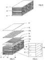
- Figure 4 schematically shows the composition of a stack of plates forming the core of an example embodiment heat-exchanger having two different types of plates 30 which are alternatingly placed in the stack.
- a first group of plates 30a comprises longitudinally extending channels 32 that extend between a first pair of opposite sides 34, 35 of the core 2
- a second group of plates 30b comprises transversely extending channels 33 that extend between a second pair of opposite sides 36, 37 of the core 2.
- the channels 32 may run substantially straight from one side of the core to an opposite side of the core, as shown in figure 4 , but many variations are of course possible, such as curved paths, zig-zag paths, etc.
- the channels 32, 33 may for example be formed by chemical etching, which is commonly known as printed circuit heat exchanger (PCHE).
- PCHE printed circuit heat exchanger
- channels may be formed in metal plates by means of pressing a plate in a pressing die having projections that form grooves or channels in the plate.
- Figure 5 shows a magnified view of a corner section of the example plate stack of figure 4 , wherein the plates 30a, 30b of the first and second groups of plates are placed alternatingly.
- the interaction of neighboring plates form flow conduits through the core, as shown in figure 5 , where open channels 32, 33 in one plate interact with the neighboring upper plate to close said open channels and form closed flow conduits.
- Many alternative designs are possible, such as having an open channel in one plate facing an open channel in a neighboring plate to form a closed flow conduit, or the like.
- each of the first and second heat exchange passages in the heat-exchanger core 2 of figure 3 and 4 comprises a plurality of flow conduits extending between a working fluid inlet surface and a working fluid outlet surface of the heat-exchanger core 2.
- the heat-exchanger is specifically arranged for withstanding very high pressure and high temperature working fluid. For this reason the at least one header of the heat-exchanger 1 is welded to the heat-exchanger core along a header-to-core joint. The header is welded along its entire peripheral contact surface with a side of the core.
- One cost-efficient approach for reducing high peak stress at the header-to-core joint is to provide the heat-exchanger core with a groove extending at least partly along the header-to-core joint.
- FIG. 6 shows a sectional perspective view of a portion of a heat-exchanger according to an example embodiment of the invention.
- the heat-exchanger comprises a header 3 welded to a core 2 along a header-to-core joint 46, wherein the header 3 comprises a fluid inlet or outlet connection 10.
- the illustrated core 2 has a plurality of channels 32 extending through the core 2 between a working fluid inlet or outlet surface 45.
- a groove 60 is formed in the working fluid inlet or outlet surface 45 along the entire header-to-core joint 46.
- Figure 7 schematically illustrates a side view of an example embodiment of the core 2 having a plurality of alternatingly stacked plates 30a, 30b from a first and second group of plates, and two endplates 31 located on opposite sides of the core 2.
- a first group of plates 30a have a plurality of channels 32 formed therein, enabling access to the flow conduits from the front side.
- a second group of plates 30b having a plurality of channels 33 formed therein.
- the illustrated core surface having opening to the channels 32 defines a working fluid inlet or outlet surface 45 of the heat-exchanger core 2.
- the groove is formed along an intended root surface of the welded header-to-core joint.
- the groove may advantageously be machined using metal cutting equipment, such as milling.
- the groove extends along the entire length of the intended header-to-core joint, however, shorter segments of groove along the header-to-core joint may be used in certain situation.
- the groove may possibly be omitted in the corner areas 40 of the header-to-core joint.
- the groove may extend along at least 50%, specifically at least 75%, more specifically at least 95% of the total length of the header-to-core joint, and most specifically along the entire length of the header-to-core joint.
- the groove may extend at least at the middle of one of the sides of the header-to-core joint, i.e. in the region halfway between the corner areas 40, and/or at the portions of the header-to-core joint being closest to the inlet or outlet connection 10,11,12,13, where the peak stresses are most significant.
- the inlet or outlet connection 10,11,12,13 is located at the center of the header 3,4,5,6 and thus the middle of the side of the header-to-core joint and the portion closest to the inlet or outlet connection is the same.
- the groove may be present at least at the longsides of the header-to-core joint.
- the groove On the sides of the header-to-core joint where the groove is present, the groove may extend along a length that is at least equal to a diameter of the inlet or outlet connection.
- Figure 8 corresponds to figure 7 but additionally with the root surface 41 of the welded header-to-core joint illustrated as a hatched area. This figure illustrates that the groove is located on an inside of, and substantially flush with, the header-to-core joint. Consequently, in a finished state of the heat-exchanger 1, the header 3, 4, 5, 6 is attached around a working fluid inlet or outlet surface of the heat-exchanger core 2 and the groove 60 is formed in said working fluid inlet or outlet surface 45.
- FIG 9 schematically shows an alternative embodiment having substantially identical core structure as the example embodiment of figure 8 , but with two working fluid inlet or outlet surfaces 45a, 45b formed in the single shown core surface.
- Each working fluid inlet or outlet surface 45a, 45b has an individual header attached along a root surface 41a, 41b of a welded header-to-core joint around the working fluid inlet or outlet surface 45a, 45b of the heat-exchanger core 2. This corresponds to a heat exchanger as shown in figure 2c .
- Figure 10 schematically illustrates a section along cut A-A of figure 8 for the purpose of more clearly illustrating the cross-sectional shape of the groove 60 according to the invention, and its position relative to the root surface 41 of the welded header-to-core joint 46.
- the lower part shown in figure 10 corresponds to an endplate 31 of the core 2, and the upper part corresponds to a side wall of the header 3, which is welded around a working fluid inlet or outlet surface 45 of the heat-exchanger core 2 by means of a weld 47 to form the header-to-core joint 46.
- the cross-section of the groove has a rounded shape, i.e. a shape free from sharp corners.
- the cross-section of the groove has a depth 61 that is larger than half the width 62 of the groove 60. This is advantageous because it provides a groove with relatively large surface area while still avoiding sharp corners. The large surface area results in reduced stress because the stress can be better distributed over the surface, and the sharp corners may result in stress concentration.
- the cross-section of the groove 60 has a substantially elliptical shape.
- the groove follows part of a shape resembling an ellipse.
- the groove substantially follows half of an ellipse, i.e. having a substantially semi-elliptical shape.
- the cross-section of the groove 60 may diverge slightly from a pure elliptical shape.
- the cross-sectional elliptic shape of the groove may approximated by few, such as about 3 to 6 or about 4 to 5 segments (arcs) of a circle, or a b-spline, or a series of curves.
- the table below shows the results of simulations made in various types of welded header-to-core joints, wherein the result shows the maximum values of equivalent (van Mises) stress occurring on an internal surface of the header-to-core 46 joint in a transition area between header 3 and core 2.
- the maximum values of equivalent (van Mises) stress may also be referred to as peak stress.
- Welded header-to-core joint Maximum equivalent (von Mises) stress Groove-less 4.0 * 10 8 Pascal Groove with semi-circular shape 3.8 * 10 8 Pascal Groove with semi-elliptical shape 3.0 * 10 8 Pascal
- a groove-less header-to-core joint is formed by simply welding the header wall to the flat surface of the core, such that a right-angle corner is formed.
- the simulation result confirms that a header-to-core joint 46 having a groove 60 with semi-elliptical cross-sectional shape has substantially lower maximal peak stress than a header-to-core joint having a groove 60 with a semi-circular cross-sectional shape.
- the result is also a strong indicator that a header-to-core joint 46 having a groove 60 with rounded cross-section and a depth 61 of the groove larger than half the width 62 of the groove 60 also exhibits a lower maximal peak stress than a header-to-core joint having a groove 60 with a semi-circular cross-sectional shape.
- a relationship between a major radius (depth 61 of groove 60) and a minor axis (width 62 of the groove 60) of the elliptical shape may for example be set in the range of 0.6 - 1.5, specifically 0.7 - 1.3, and more specifically 0.9 - 1.1.
- An advantage of simply providing a groove 60 in the working fluid inlet or outlet surface 45 of the heat-exchanger core 2 is that a butt welded header-to-core joint 46 may be accomplished without having to lower the working fluid inlet or outlet surface 45, for example by machining, because the root surface 41 of the welded header-to-core joint 46 does not protrude above a plane of said inlet or outlet surface 45. This means that a butt welded header-to-core joint 46 can be finished merely by means of the groove.
- the groove is preferably located so that an outer peripheral edge 65 of the groove 60 substantially coincides with the interior edge 66 of the header wall after assembly and fastening of the header to the core 2 for enabling a flush transition between the header 4 and groove 60.
- the depth and width of the groove is preferably selected in accordance with the wall thickness of the header, i.e. the thickness of a wall of the header next to the header-to-core joint.
- a major radius 61 of the elliptical shape may be set in the range of 50% - 150%, specifically 75% - 125%, of a thickness 70 of the header wall in the area of the header-to-core joint 46.
- the thickness of the header wall is typically in the range of 5 to 75 millimeters.
- the major radius of the elliptical shape may be set in the range of 2.5 - 112.5 millimeters, specifically in the range of 5 - 100 millimeters, more specifically in the range of 10 - 75 millimeters.
- a center 67 of the substantially elliptical shape of the groove 60 may according to an example embodiment be set to substantially coincide with a plane 68 of said inlet or outlet surface 45.
- the groove 60 may be made more or less shallow.
- a more shallow elliptical-shaped groove 60 is shown in the example embodiment of figure 12 , wherein the center 67 of the substantially elliptical shape of the groove 60 is located a distance corresponding to about 25% of the major radius of the elliptical shape above the plane 68 of said inlet or outlet surface 45.
- a less shallow elliptical-shaped groove 60 is shown in the example embodiment of figure 13 , wherein the center 67 of the substantially elliptical shape of the groove 60 is located a distance corresponding to about 25% of the major radius of the elliptical shape below the plane 68 of said inlet or outlet surface 45.
- a center of the elliptical shape of the groove may be located in a range extending from a position corresponding to 25% of a major radius of the elliptical shape below a plane of said inlet or outlet surface to a position corresponding to 25% of the major radius of the elliptical shape above the plane of said inlet or outlet surface, specifically in a range extending from a position corresponding to 10% of a major radius of the elliptical shape below a plane of said inlet or outlet surface to a position corresponding to 10% of the major radius of the elliptical shape above the plane of said inlet or outlet surface.
- the disclosure also relates to a method for manufacturing a heat-exchanger 1 comprising a heat-exchanger core 2 having a plurality of heat-exchange passages and a header 3, 4, 5, 6 for conveying working fluid to or from the plurality of heat-exchange passages.
- the method comprises the following steps S1-S3, which is also illustrated in figure 14 .
- the method comprises:
Claims (14)
- Échangeur de chaleur (1) comprenant :un coeur d'échangeur de chaleur (2) présentant un premier passage d'échange de chaleur pour un premier fluide de travail destiné à être impliqué dans un processus d'échange de chaleur, et un second passage d'échange de chaleur pour un second fluide de travail destiné à être impliqué dans le processus d'échange de chaleur ; etun collecteur (3, 4, 5, 6) comprenant un conduit permettant de convoyer le fluide de travail vers ou depuis au moins un du premier et du second passages d'échange de chaleur, dans lequel le collecteur (3, 4, 5, 6) est soudé au coeur de l'échangeur de chaleur (2) le long d'un joint de collecteur à coeur (46),dans lequel le coeur d'échangeur de chaleur (2) présente une cannelure (60, 60a, 60b) s'étendant au moins partiellement le long du joint de collecteur au coeur (46), dans lequel une coupe transversale de la cannelure (60, 60a, 60b) présente une forme arrondie, caractérisé en ce qu'une profondeur (61) de la cannelure (60, 60a, 60b) est supérieure à la moitié de la largeur (62) de la cannelure (60, 60a, 60b), et dans lequel une coupe transversale de la cannelure (60) présente une forme sensiblement elliptique.
- Échangeur de chaleur selon l'une quelconque des revendications 1, dans lequel le collecteur (3, 4, 5, 6) est fixé autour d'une surface d'entrée ou de sortie d'un fluide de travail (45, 45a, 45b) du coeur d'échangeur de chaleur (2), et dans lequel la cannelure (60, 60a, 60b) est formée dans ladite surface d'entrée ou de sortie de fluide de travail (45, 45a, 45b).
- Échangeur de chaleur selon l'une quelconque des revendications 1 à 2, dans lequel un centre (67) de la forme elliptique de la cannelure (60, 60a, 60b) est situé dans une plage s'étendant depuis une position correspondant à 25 % d'un rayon majeur de la forme elliptique sous un plan (68) de ladite surface d'entrée ou sortie (45, 45a, 45b) vers une position correspondant à 25 % du rayon majeur de la forme elliptique au-dessus du plan (68) de ladite surface d'entrée ou de sortie, spécifiquement dans lequel un centre (67) de la forme elliptique de la cannelure (60, 60a, 60b) coïncide sensiblement avec le plan (68) de ladite surface d'entrée ou de sortie (45, 45a, 45b).
- Échangeur de chaleur selon l'une quelconque des revendications 1 à 3, dans lequel une relation entre un rayon majeur et un axe mineur de la forme elliptique est comprise dans la plage de 0,6 à 1,5, spécifiquement de 0,7 à 1,3, et plus spécifiquement de 0,9 à 1,1.
- Échangeur de chaleur selon l'une quelconque des revendications 1 à 4, dans lequel un rayon majeur de la forme elliptique est compris dans la plage de 50 % à 150 %, spécifiquement 75 % à 125 % d'une épaisseur (70) de la paroi de collecteur.
- Échangeur de chaleur selon l'une quelconque des revendications 1 à 5, dans lequel la cannelure (60, 60a, 60b) est formée par un usinage en utilisant un équipement de coupe métallique.
- Échangeur de chaleur selon l'une quelconque des revendications 1 à 6, dans lequel la cannelure (60, 60a, 60b) s'étend le long d'au moins 50 %, spécifiquement au moins 75 %, plus spécifiquement au moins 95 % de la longueur totale du joint du collecteur au coeur (46), et plus spécifiquement, le long de toute la longueur du joint du collecteur au coeur (46).
- Échangeur de chaleur selon l'une quelconque des revendications 2 à 7, dans lequel une surface de base (41) du joint de collecteur au coeur soudé (46) ne ressort pas au-dessus d'un plan (68) de ladite surface d'entrée ou sortie (45, 45a, 45b).
- Échangeur de chaleur selon l'une quelconque des revendications 1 à 8, dans lequel le coeur de l'échangeur de chaleur (2) est constitué d'une pluralité de plaques empilées (30, 30a, 30b) disposées parallèlement l'une à l'autre et jointes les unes aux autres, de préférence par un soudage à l'état solide, un brasage, ou une combinaison de ces deux procédés.
- Échangeur de chaleur selon l'une quelconque des revendications 1 à 9, dans lequel chacun du premier et du second passages d'échange de chaleur comprend une pluralité de conduits d'écoulement s'étendant entre une surface d'entrée de fluide de travail (45, 45a, 45b) et une surface de sortie de fluide de travail (45, 45a, 45b) du coeur d'échangeur de chaleur (2).
- Échangeur de chaleur selon la revendication 10, dans lequel la pluralité de conduits d'écoulement est constituée de canaux ouverts (32, 33) dans une surface latérale de plaques empilées individuelles (30, 30a, 30b).
- Échangeur de chaleur selon l'une quelconque des revendications 1 à 11, dans lequel l'échangeur de chaleur (1) est un échangeur de chaleur collé par diffusion.
- Échangeur de chaleur selon l'une quelconque des revendications 2 à 12, dans lequel chacune des surfaces d'entrée de fluide de travail et de sortie de fluide de travail (45, 45a, 45b) du premier et du second passages d'échange de chaleur comprend un collecteur individuel (3, 4, 5, 6) qui y est soudé.
- Procédé de fabrication d'un échangeur de chaleur (1) comprenant un coeur d'échangeur de chaleur (2) présentant une pluralité de passages d'échange de chaleur et un collecteur (3, 4, 5, 6) permettant de convoyer un fluide de travail vers ou depuis la pluralité de passages d'échange de chaleur, le procédé comprenant
la fourniture d'un coeur d'échangeur de chaleur (2) ;
l'usinage d'une cannelure (60, 60a, 60b) dans le coeur d'échangeur de chaleur (2) au moins partiellement le long d'un joint de collecteur à coeur prévu (46), dans lequel une coupe transversale de la cannelure (60, 60a, 60b) présente une forme arrondie avec une profondeur (61) de la cannelure (60, 60a, 60b) supérieure à la moitié de la largeur (62) de la cannelure (60, 60a, 60b), et dans lequel une coupe transversale de la cannelure (60) présente une forme sensiblement elliptique,
le soudage du collecteur (3, 4, 5, 6) au coeur d'échangeur de chaleur (2) afin de former ledit joint de collecteur à coeur (46).
Priority Applications (11)
| Application Number | Priority Date | Filing Date | Title |
|---|---|---|---|
| DK16461579.1T DK3339793T3 (da) | 2016-12-23 | 2016-12-23 | Varmeveksler med opsamler svejset til kernen |
| PL16461579T PL3339793T3 (pl) | 2016-12-23 | 2016-12-23 | Wymiennik ciepła z kolektorem spawanym do rdzenia |
| EP16461579.1A EP3339793B1 (fr) | 2016-12-23 | 2016-12-23 | Échangeur de chaleur avec collecteur soudé au ceur |
| CN201780079679.XA CN110088558B (zh) | 2016-12-23 | 2017-12-21 | 热交换器 |
| JP2019534270A JP2020502470A (ja) | 2016-12-23 | 2017-12-21 | 熱交換器 |
| KR1020217014458A KR20210059794A (ko) | 2016-12-23 | 2017-12-21 | 열 교환기 |
| EP17835677.0A EP3559584B1 (fr) | 2016-12-23 | 2017-12-21 | Échangeur de chaleur avec collecteur soudé au ceur |
| US16/461,114 US20190368829A1 (en) | 2016-12-23 | 2017-12-21 | Heat exchanger |
| KR1020197020978A KR20190099466A (ko) | 2016-12-23 | 2017-12-21 | 열 교환기 |
| PCT/EP2017/084036 WO2018115253A1 (fr) | 2016-12-23 | 2017-12-21 | Échangeur de chaleur |
| JP2021117024A JP2022008275A (ja) | 2016-12-23 | 2021-07-15 | 熱交換器 |
Applications Claiming Priority (1)
| Application Number | Priority Date | Filing Date | Title |
|---|---|---|---|
| EP16461579.1A EP3339793B1 (fr) | 2016-12-23 | 2016-12-23 | Échangeur de chaleur avec collecteur soudé au ceur |
Publications (2)
| Publication Number | Publication Date |
|---|---|
| EP3339793A1 EP3339793A1 (fr) | 2018-06-27 |
| EP3339793B1 true EP3339793B1 (fr) | 2019-06-19 |
Family
ID=57609828
Family Applications (2)
| Application Number | Title | Priority Date | Filing Date |
|---|---|---|---|
| EP16461579.1A Active EP3339793B1 (fr) | 2016-12-23 | 2016-12-23 | Échangeur de chaleur avec collecteur soudé au ceur |
| EP17835677.0A Active EP3559584B1 (fr) | 2016-12-23 | 2017-12-21 | Échangeur de chaleur avec collecteur soudé au ceur |
Family Applications After (1)
| Application Number | Title | Priority Date | Filing Date |
|---|---|---|---|
| EP17835677.0A Active EP3559584B1 (fr) | 2016-12-23 | 2017-12-21 | Échangeur de chaleur avec collecteur soudé au ceur |
Country Status (8)
| Country | Link |
|---|---|
| US (1) | US20190368829A1 (fr) |
| EP (2) | EP3339793B1 (fr) |
| JP (2) | JP2020502470A (fr) |
| KR (2) | KR20210059794A (fr) |
| CN (1) | CN110088558B (fr) |
| DK (1) | DK3339793T3 (fr) |
| PL (1) | PL3339793T3 (fr) |
| WO (1) | WO2018115253A1 (fr) |
Families Citing this family (7)
| Publication number | Priority date | Publication date | Assignee | Title |
|---|---|---|---|---|
| US11274884B2 (en) * | 2019-03-29 | 2022-03-15 | Dana Canada Corporation | Heat exchanger module with an adapter module for direct mounting to a vehicle component |
| FR3099564B1 (fr) * | 2019-07-29 | 2021-07-02 | Commissariat Energie Atomique | Module d’échangeur de chaleur à deux circuits de fluides, notamment échangeur de chaleur de réacteur nucléaire |
| JP2021076297A (ja) * | 2019-11-08 | 2021-05-20 | 日本電産株式会社 | 熱伝導部材 |
| US11255610B2 (en) * | 2020-01-22 | 2022-02-22 | Cooler Master Co., Ltd. | Pulse loop heat exchanger and manufacturing method of the same |
| FR3110099B1 (fr) * | 2020-05-15 | 2022-04-15 | Lair Liquide Sa Pour L’Etude Et Lexploitation Des Procedes Georges Claude | Procédé de fabrication d’un échangeur de chaleur comportant une sonde de température |
| EP4342624A1 (fr) * | 2022-09-20 | 2024-03-27 | Alfa Laval Vicarb | Module d'échangeur de chaleur, procédé de soudage d'échangeur de chaleur et ensemble échangeur de chaleur |
| CN116642353B (zh) * | 2023-07-24 | 2023-10-24 | 中国核动力研究设计院 | 一种集流结构、换热芯体和换热器 |
Family Cites Families (12)
| Publication number | Priority date | Publication date | Assignee | Title |
|---|---|---|---|---|
| JPS59200197A (ja) * | 1983-04-28 | 1984-11-13 | Hitachi Ltd | 給水加熱器 |
| JPS6237687A (ja) * | 1985-08-08 | 1987-02-18 | ヒ−トリツク・ピ−テイ−ワイ・リミテド | 熱交換器 |
| JPH01129591U (fr) * | 1988-02-19 | 1989-09-04 | ||
| EP0693593B1 (fr) * | 1994-07-19 | 1999-12-22 | Technip France | Procédé d'assemblage de tronçons de grande longueur de membrures des jambes de support d'une plate-forme pétrolière |
| CN2645023Y (zh) * | 2003-08-13 | 2004-09-29 | 华东理工大学 | 一种具有凹槽的换热器管板 |
| FR2858845B1 (fr) * | 2003-08-13 | 2005-11-11 | Framatome Anp | Echangeur de chaleur et procede de fabrication |
| DE102008018594A1 (de) * | 2007-04-11 | 2008-10-16 | Behr Gmbh & Co. Kg | Wärmetauscher |
| CN101687266A (zh) * | 2008-06-11 | 2010-03-31 | 三菱重工业株式会社 | 用于结构构件的法兰接头 |
| JP5320010B2 (ja) * | 2008-10-07 | 2013-10-23 | 三菱重工業株式会社 | 管寄せ管台の溶接構造 |
| KR20130081440A (ko) * | 2012-01-09 | 2013-07-17 | 주식회사 동화엔텍 | 쉘앤튜브 열교환기의 튜브시트와 튜브의 접합방법 및 쉘앤튜브 열교환기 |
| JP2013243232A (ja) * | 2012-05-21 | 2013-12-05 | Ngk Spark Plug Co Ltd | セラミックパッケージ用金属枠体およびセラミックパッケージ |
| JP6451476B2 (ja) * | 2015-04-24 | 2019-01-16 | 新日鐵住金株式会社 | 鋼床版 |
-
2016
- 2016-12-23 DK DK16461579.1T patent/DK3339793T3/da active
- 2016-12-23 EP EP16461579.1A patent/EP3339793B1/fr active Active
- 2016-12-23 PL PL16461579T patent/PL3339793T3/pl unknown
-
2017
- 2017-12-21 KR KR1020217014458A patent/KR20210059794A/ko not_active Application Discontinuation
- 2017-12-21 US US16/461,114 patent/US20190368829A1/en not_active Abandoned
- 2017-12-21 WO PCT/EP2017/084036 patent/WO2018115253A1/fr unknown
- 2017-12-21 JP JP2019534270A patent/JP2020502470A/ja active Pending
- 2017-12-21 CN CN201780079679.XA patent/CN110088558B/zh active Active
- 2017-12-21 EP EP17835677.0A patent/EP3559584B1/fr active Active
- 2017-12-21 KR KR1020197020978A patent/KR20190099466A/ko not_active Application Discontinuation
-
2021
- 2021-07-15 JP JP2021117024A patent/JP2022008275A/ja active Pending
Non-Patent Citations (1)
| Title |
|---|
| None * |
Also Published As
| Publication number | Publication date |
|---|---|
| JP2022008275A (ja) | 2022-01-13 |
| US20190368829A1 (en) | 2019-12-05 |
| KR20210059794A (ko) | 2021-05-25 |
| KR20190099466A (ko) | 2019-08-27 |
| CN110088558B (zh) | 2021-05-11 |
| PL3339793T3 (pl) | 2019-10-31 |
| JP2020502470A (ja) | 2020-01-23 |
| WO2018115253A1 (fr) | 2018-06-28 |
| EP3339793A1 (fr) | 2018-06-27 |
| EP3559584A1 (fr) | 2019-10-30 |
| DK3339793T3 (da) | 2019-09-23 |
| EP3559584B1 (fr) | 2021-09-01 |
| CN110088558A (zh) | 2019-08-02 |
Similar Documents
| Publication | Publication Date | Title |
|---|---|---|
| EP3339793B1 (fr) | Échangeur de chaleur avec collecteur soudé au ceur | |
| US10180289B2 (en) | Flow balanced heat exchanger for battery thermal management | |
| CN102575905B (zh) | 用于制造热交换器板束的方法 | |
| EP3633300B1 (fr) | Conception de noyau d'échangeur thermique à ailettes-plaques pour une fabrication améliorée | |
| DK178441B1 (en) | Method of producing a heat exchanger and a heat exchanger | |
| US20070062682A1 (en) | Multiple-hole tube for heat exchanger and manufacturing method thereof | |
| JP2002071283A (ja) | 熱交換器 | |
| EP3650796B1 (fr) | Échangeur de chaleur | |
| US10197340B2 (en) | Exchanger element for a heat exchanger, heat exchanger comprising such an exchanger element and method for the production of such an exchanger element | |
| EP3267137B1 (fr) | Échangeur de chaleur à passages entrelacés | |
| WO2020007787A1 (fr) | Échangeur de chaleur pour gaz d'échappement, en particulier pour gaz d'échappement de moteur, et corps perturbateur pour ledit échangeur | |
| CN112513553A (zh) | 具有加强盖的板式换热器和生产该加强盖及其组件的方法 | |
| JP7472564B2 (ja) | 積層体及び積層体の製造方法 | |
| US11112191B2 (en) | Heat exchanger with turbulating inserts | |
| JP2006078154A (ja) | プレート式熱交換器及びその製造方法 | |
| JPH038562A (ja) | 積層式熱交換器 | |
| WO2024061816A1 (fr) | Module d'échangeur de chaleur, procédé de soudage d'échangeur de chaleur et ensemble échangeur de chaleur | |
| JP2007024440A (ja) | 熱交換器 | |
| JP2001349680A (ja) | プレートフィン熱交換器の構造 |
Legal Events
| Date | Code | Title | Description |
|---|---|---|---|
| PUAI | Public reference made under article 153(3) epc to a published international application that has entered the european phase |
Free format text: ORIGINAL CODE: 0009012 |
|
| STAA | Information on the status of an ep patent application or granted ep patent |
Free format text: STATUS: THE APPLICATION HAS BEEN PUBLISHED |
|
| AK | Designated contracting states |
Kind code of ref document: A1 Designated state(s): AL AT BE BG CH CY CZ DE DK EE ES FI FR GB GR HR HU IE IS IT LI LT LU LV MC MK MT NL NO PL PT RO RS SE SI SK SM TR |
|
| AX | Request for extension of the european patent |
Extension state: BA ME |
|
| STAA | Information on the status of an ep patent application or granted ep patent |
Free format text: STATUS: REQUEST FOR EXAMINATION WAS MADE |
|
| 17P | Request for examination filed |
Effective date: 20181221 |
|
| RBV | Designated contracting states (corrected) |
Designated state(s): AL AT BE BG CH CY CZ DE DK EE ES FI FR GB GR HR HU IE IS IT LI LT LU LV MC MK MT NL NO PL PT RO RS SE SI SK SM TR |
|
| GRAP | Despatch of communication of intention to grant a patent |
Free format text: ORIGINAL CODE: EPIDOSNIGR1 |
|
| STAA | Information on the status of an ep patent application or granted ep patent |
Free format text: STATUS: GRANT OF PATENT IS INTENDED |
|
| INTG | Intention to grant announced |
Effective date: 20190222 |
|
| GRAS | Grant fee paid |
Free format text: ORIGINAL CODE: EPIDOSNIGR3 |
|
| GRAA | (expected) grant |
Free format text: ORIGINAL CODE: 0009210 |
|
| STAA | Information on the status of an ep patent application or granted ep patent |
Free format text: STATUS: THE PATENT HAS BEEN GRANTED |
|
| AK | Designated contracting states |
Kind code of ref document: B1 Designated state(s): AL AT BE BG CH CY CZ DE DK EE ES FI FR GB GR HR HU IE IS IT LI LT LU LV MC MK MT NL NO PL PT RO RS SE SI SK SM TR |
|
| REG | Reference to a national code |
Ref country code: GB Ref legal event code: FG4D |
|
| REG | Reference to a national code |
Ref country code: CH Ref legal event code: EP |
|
| REG | Reference to a national code |
Ref country code: IE Ref legal event code: FG4D |
|
| REG | Reference to a national code |
Ref country code: DE Ref legal event code: R096 Ref document number: 602016015500 Country of ref document: DE |
|
| REG | Reference to a national code |
Ref country code: AT Ref legal event code: REF Ref document number: 1146066 Country of ref document: AT Kind code of ref document: T Effective date: 20190715 |
|
| REG | Reference to a national code |
Ref country code: SE Ref legal event code: TRGR |
|
| REG | Reference to a national code |
Ref country code: NL Ref legal event code: FP |
|
| REG | Reference to a national code |
Ref country code: DK Ref legal event code: T3 Effective date: 20190919 |
|
| PG25 | Lapsed in a contracting state [announced via postgrant information from national office to epo] |
Ref country code: HR Free format text: LAPSE BECAUSE OF FAILURE TO SUBMIT A TRANSLATION OF THE DESCRIPTION OR TO PAY THE FEE WITHIN THE PRESCRIBED TIME-LIMIT Effective date: 20190619 Ref country code: AL Free format text: LAPSE BECAUSE OF FAILURE TO SUBMIT A TRANSLATION OF THE DESCRIPTION OR TO PAY THE FEE WITHIN THE PRESCRIBED TIME-LIMIT Effective date: 20190619 Ref country code: LT Free format text: LAPSE BECAUSE OF FAILURE TO SUBMIT A TRANSLATION OF THE DESCRIPTION OR TO PAY THE FEE WITHIN THE PRESCRIBED TIME-LIMIT Effective date: 20190619 |
|
| REG | Reference to a national code |
Ref country code: NO Ref legal event code: T2 Effective date: 20190619 |
|
| REG | Reference to a national code |
Ref country code: LT Ref legal event code: MG4D |
|
| PG25 | Lapsed in a contracting state [announced via postgrant information from national office to epo] |
Ref country code: BG Free format text: LAPSE BECAUSE OF FAILURE TO SUBMIT A TRANSLATION OF THE DESCRIPTION OR TO PAY THE FEE WITHIN THE PRESCRIBED TIME-LIMIT Effective date: 20190919 Ref country code: GR Free format text: LAPSE BECAUSE OF FAILURE TO SUBMIT A TRANSLATION OF THE DESCRIPTION OR TO PAY THE FEE WITHIN THE PRESCRIBED TIME-LIMIT Effective date: 20190920 Ref country code: RS Free format text: LAPSE BECAUSE OF FAILURE TO SUBMIT A TRANSLATION OF THE DESCRIPTION OR TO PAY THE FEE WITHIN THE PRESCRIBED TIME-LIMIT Effective date: 20190619 Ref country code: LV Free format text: LAPSE BECAUSE OF FAILURE TO SUBMIT A TRANSLATION OF THE DESCRIPTION OR TO PAY THE FEE WITHIN THE PRESCRIBED TIME-LIMIT Effective date: 20190619 |
|
| REG | Reference to a national code |
Ref country code: AT Ref legal event code: MK05 Ref document number: 1146066 Country of ref document: AT Kind code of ref document: T Effective date: 20190619 |
|
| PG25 | Lapsed in a contracting state [announced via postgrant information from national office to epo] |
Ref country code: CZ Free format text: LAPSE BECAUSE OF FAILURE TO SUBMIT A TRANSLATION OF THE DESCRIPTION OR TO PAY THE FEE WITHIN THE PRESCRIBED TIME-LIMIT Effective date: 20190619 Ref country code: SK Free format text: LAPSE BECAUSE OF FAILURE TO SUBMIT A TRANSLATION OF THE DESCRIPTION OR TO PAY THE FEE WITHIN THE PRESCRIBED TIME-LIMIT Effective date: 20190619 Ref country code: RO Free format text: LAPSE BECAUSE OF FAILURE TO SUBMIT A TRANSLATION OF THE DESCRIPTION OR TO PAY THE FEE WITHIN THE PRESCRIBED TIME-LIMIT Effective date: 20190619 Ref country code: EE Free format text: LAPSE BECAUSE OF FAILURE TO SUBMIT A TRANSLATION OF THE DESCRIPTION OR TO PAY THE FEE WITHIN THE PRESCRIBED TIME-LIMIT Effective date: 20190619 Ref country code: AT Free format text: LAPSE BECAUSE OF FAILURE TO SUBMIT A TRANSLATION OF THE DESCRIPTION OR TO PAY THE FEE WITHIN THE PRESCRIBED TIME-LIMIT Effective date: 20190619 Ref country code: PT Free format text: LAPSE BECAUSE OF FAILURE TO SUBMIT A TRANSLATION OF THE DESCRIPTION OR TO PAY THE FEE WITHIN THE PRESCRIBED TIME-LIMIT Effective date: 20191021 |
|
| PG25 | Lapsed in a contracting state [announced via postgrant information from national office to epo] |
Ref country code: SM Free format text: LAPSE BECAUSE OF FAILURE TO SUBMIT A TRANSLATION OF THE DESCRIPTION OR TO PAY THE FEE WITHIN THE PRESCRIBED TIME-LIMIT Effective date: 20190619 Ref country code: IS Free format text: LAPSE BECAUSE OF FAILURE TO SUBMIT A TRANSLATION OF THE DESCRIPTION OR TO PAY THE FEE WITHIN THE PRESCRIBED TIME-LIMIT Effective date: 20191019 Ref country code: ES Free format text: LAPSE BECAUSE OF FAILURE TO SUBMIT A TRANSLATION OF THE DESCRIPTION OR TO PAY THE FEE WITHIN THE PRESCRIBED TIME-LIMIT Effective date: 20190619 |
|
| PG25 | Lapsed in a contracting state [announced via postgrant information from national office to epo] |
Ref country code: TR Free format text: LAPSE BECAUSE OF FAILURE TO SUBMIT A TRANSLATION OF THE DESCRIPTION OR TO PAY THE FEE WITHIN THE PRESCRIBED TIME-LIMIT Effective date: 20190619 |
|
| PG25 | Lapsed in a contracting state [announced via postgrant information from national office to epo] |
Ref country code: IS Free format text: LAPSE BECAUSE OF FAILURE TO SUBMIT A TRANSLATION OF THE DESCRIPTION OR TO PAY THE FEE WITHIN THE PRESCRIBED TIME-LIMIT Effective date: 20200224 |
|
| REG | Reference to a national code |
Ref country code: DE Ref legal event code: R097 Ref document number: 602016015500 Country of ref document: DE |
|
| PLBE | No opposition filed within time limit |
Free format text: ORIGINAL CODE: 0009261 |
|
| STAA | Information on the status of an ep patent application or granted ep patent |
Free format text: STATUS: NO OPPOSITION FILED WITHIN TIME LIMIT |
|
| PG2D | Information on lapse in contracting state deleted |
Ref country code: IS |
|
| REG | Reference to a national code |
Ref country code: CH Ref legal event code: PL |
|
| 26N | No opposition filed |
Effective date: 20200603 |
|
| PG25 | Lapsed in a contracting state [announced via postgrant information from national office to epo] |
Ref country code: SI Free format text: LAPSE BECAUSE OF FAILURE TO SUBMIT A TRANSLATION OF THE DESCRIPTION OR TO PAY THE FEE WITHIN THE PRESCRIBED TIME-LIMIT Effective date: 20190619 Ref country code: MC Free format text: LAPSE BECAUSE OF FAILURE TO SUBMIT A TRANSLATION OF THE DESCRIPTION OR TO PAY THE FEE WITHIN THE PRESCRIBED TIME-LIMIT Effective date: 20190619 |
|
| PG25 | Lapsed in a contracting state [announced via postgrant information from national office to epo] |
Ref country code: LU Free format text: LAPSE BECAUSE OF NON-PAYMENT OF DUE FEES Effective date: 20191223 Ref country code: IE Free format text: LAPSE BECAUSE OF NON-PAYMENT OF DUE FEES Effective date: 20191223 |
|
| PG25 | Lapsed in a contracting state [announced via postgrant information from national office to epo] |
Ref country code: LI Free format text: LAPSE BECAUSE OF NON-PAYMENT OF DUE FEES Effective date: 20191231 Ref country code: CH Free format text: LAPSE BECAUSE OF NON-PAYMENT OF DUE FEES Effective date: 20191231 |
|
| PG25 | Lapsed in a contracting state [announced via postgrant information from national office to epo] |
Ref country code: CY Free format text: LAPSE BECAUSE OF FAILURE TO SUBMIT A TRANSLATION OF THE DESCRIPTION OR TO PAY THE FEE WITHIN THE PRESCRIBED TIME-LIMIT Effective date: 20190619 |
|
| PG25 | Lapsed in a contracting state [announced via postgrant information from national office to epo] |
Ref country code: MT Free format text: LAPSE BECAUSE OF FAILURE TO SUBMIT A TRANSLATION OF THE DESCRIPTION OR TO PAY THE FEE WITHIN THE PRESCRIBED TIME-LIMIT Effective date: 20190619 Ref country code: HU Free format text: LAPSE BECAUSE OF FAILURE TO SUBMIT A TRANSLATION OF THE DESCRIPTION OR TO PAY THE FEE WITHIN THE PRESCRIBED TIME-LIMIT; INVALID AB INITIO Effective date: 20161223 |
|
| PG25 | Lapsed in a contracting state [announced via postgrant information from national office to epo] |
Ref country code: MK Free format text: LAPSE BECAUSE OF FAILURE TO SUBMIT A TRANSLATION OF THE DESCRIPTION OR TO PAY THE FEE WITHIN THE PRESCRIBED TIME-LIMIT Effective date: 20190619 |
|
| PGFP | Annual fee paid to national office [announced via postgrant information from national office to epo] |
Ref country code: BE Payment date: 20221118 Year of fee payment: 7 |
|
| P01 | Opt-out of the competence of the unified patent court (upc) registered |
Effective date: 20230421 |
|
| PGFP | Annual fee paid to national office [announced via postgrant information from national office to epo] |
Ref country code: PL Payment date: 20230928 Year of fee payment: 8 |
|
| PGFP | Annual fee paid to national office [announced via postgrant information from national office to epo] |
Ref country code: NL Payment date: 20231116 Year of fee payment: 8 |
|
| PGFP | Annual fee paid to national office [announced via postgrant information from national office to epo] |
Ref country code: GB Payment date: 20231102 Year of fee payment: 8 |
|
| PGFP | Annual fee paid to national office [announced via postgrant information from national office to epo] |
Ref country code: SE Payment date: 20231110 Year of fee payment: 8 Ref country code: NO Payment date: 20231212 Year of fee payment: 8 Ref country code: IT Payment date: 20231110 Year of fee payment: 8 Ref country code: FR Payment date: 20231108 Year of fee payment: 8 Ref country code: FI Payment date: 20231219 Year of fee payment: 8 Ref country code: DK Payment date: 20231214 Year of fee payment: 8 Ref country code: DE Payment date: 20231031 Year of fee payment: 8 |
|
| PGFP | Annual fee paid to national office [announced via postgrant information from national office to epo] |
Ref country code: BE Payment date: 20231121 Year of fee payment: 8 |