EP3339616A1 - Steuerungsvorrichtung für verbrennungsmotor - Google Patents
Steuerungsvorrichtung für verbrennungsmotor Download PDFInfo
- Publication number
- EP3339616A1 EP3339616A1 EP17208881.7A EP17208881A EP3339616A1 EP 3339616 A1 EP3339616 A1 EP 3339616A1 EP 17208881 A EP17208881 A EP 17208881A EP 3339616 A1 EP3339616 A1 EP 3339616A1
- Authority
- EP
- European Patent Office
- Prior art keywords
- fuel
- injection
- auxiliary fuel
- injection amount
- target injection
- Prior art date
- Legal status (The legal status is an assumption and is not a legal conclusion. Google has not performed a legal analysis and makes no representation as to the accuracy of the status listed.)
- Granted
Links
- 238000002485 combustion reaction Methods 0.000 title claims abstract description 135
- 238000002347 injection Methods 0.000 claims abstract description 346
- 239000007924 injection Substances 0.000 claims abstract description 346
- 239000000446 fuel Substances 0.000 claims abstract description 225
- 230000020169 heat generation Effects 0.000 claims abstract description 74
- 230000000875 corresponding effect Effects 0.000 description 18
- 230000001276 controlling effect Effects 0.000 description 14
- QVGXLLKOCUKJST-UHFFFAOYSA-N atomic oxygen Chemical compound [O] QVGXLLKOCUKJST-UHFFFAOYSA-N 0.000 description 10
- 239000007789 gas Substances 0.000 description 10
- 239000001301 oxygen Substances 0.000 description 10
- 229910052760 oxygen Inorganic materials 0.000 description 10
- 230000015572 biosynthetic process Effects 0.000 description 5
- 239000000203 mixture Substances 0.000 description 5
- MWUXSHHQAYIFBG-UHFFFAOYSA-N nitrogen oxide Inorganic materials O=[N] MWUXSHHQAYIFBG-UHFFFAOYSA-N 0.000 description 5
- 230000001052 transient effect Effects 0.000 description 5
- 230000006835 compression Effects 0.000 description 3
- 238000007906 compression Methods 0.000 description 3
- 239000002828 fuel tank Substances 0.000 description 3
- 238000011144 upstream manufacturing Methods 0.000 description 3
- 238000001816 cooling Methods 0.000 description 2
- 239000000498 cooling water Substances 0.000 description 2
- 238000007599 discharging Methods 0.000 description 2
- 238000002474 experimental method Methods 0.000 description 2
- 238000005086 pumping Methods 0.000 description 2
- 239000004071 soot Substances 0.000 description 2
- 239000000126 substance Substances 0.000 description 2
- 230000002457 bidirectional effect Effects 0.000 description 1
- 239000003054 catalyst Substances 0.000 description 1
- 238000004140 cleaning Methods 0.000 description 1
- 230000002596 correlated effect Effects 0.000 description 1
- 230000003111 delayed effect Effects 0.000 description 1
- 230000000694 effects Effects 0.000 description 1
- 238000001704 evaporation Methods 0.000 description 1
- 230000008020 evaporation Effects 0.000 description 1
- 230000012447 hatching Effects 0.000 description 1
- 238000004519 manufacturing process Methods 0.000 description 1
- 238000000746 purification Methods 0.000 description 1
- 238000010992 reflux Methods 0.000 description 1
- 230000000630 rising effect Effects 0.000 description 1
- 239000000779 smoke Substances 0.000 description 1
- 230000001629 suppression Effects 0.000 description 1
Images


Classifications
-
- F—MECHANICAL ENGINEERING; LIGHTING; HEATING; WEAPONS; BLASTING
- F02—COMBUSTION ENGINES; HOT-GAS OR COMBUSTION-PRODUCT ENGINE PLANTS
- F02D—CONTROLLING COMBUSTION ENGINES
- F02D41/00—Electrical control of supply of combustible mixture or its constituents
- F02D41/0025—Controlling engines characterised by use of non-liquid fuels, pluralities of fuels, or non-fuel substances added to the combustible mixtures
- F02D41/0027—Controlling engines characterised by use of non-liquid fuels, pluralities of fuels, or non-fuel substances added to the combustible mixtures the fuel being gaseous
-
- F—MECHANICAL ENGINEERING; LIGHTING; HEATING; WEAPONS; BLASTING
- F02—COMBUSTION ENGINES; HOT-GAS OR COMBUSTION-PRODUCT ENGINE PLANTS
- F02D—CONTROLLING COMBUSTION ENGINES
- F02D35/00—Controlling engines, dependent on conditions exterior or interior to engines, not otherwise provided for
- F02D35/02—Controlling engines, dependent on conditions exterior or interior to engines, not otherwise provided for on interior conditions
- F02D35/028—Controlling engines, dependent on conditions exterior or interior to engines, not otherwise provided for on interior conditions by determining the combustion timing or phasing
-
- F—MECHANICAL ENGINEERING; LIGHTING; HEATING; WEAPONS; BLASTING
- F02—COMBUSTION ENGINES; HOT-GAS OR COMBUSTION-PRODUCT ENGINE PLANTS
- F02D—CONTROLLING COMBUSTION ENGINES
- F02D41/00—Electrical control of supply of combustible mixture or its constituents
- F02D41/0025—Controlling engines characterised by use of non-liquid fuels, pluralities of fuels, or non-fuel substances added to the combustible mixtures
- F02D41/0047—Controlling exhaust gas recirculation [EGR]
- F02D41/005—Controlling exhaust gas recirculation [EGR] according to engine operating conditions
- F02D41/0057—Specific combustion modes
-
- F—MECHANICAL ENGINEERING; LIGHTING; HEATING; WEAPONS; BLASTING
- F02—COMBUSTION ENGINES; HOT-GAS OR COMBUSTION-PRODUCT ENGINE PLANTS
- F02D—CONTROLLING COMBUSTION ENGINES
- F02D41/00—Electrical control of supply of combustible mixture or its constituents
- F02D41/30—Controlling fuel injection
- F02D41/3011—Controlling fuel injection according to or using specific or several modes of combustion
- F02D41/3017—Controlling fuel injection according to or using specific or several modes of combustion characterised by the mode(s) being used
- F02D41/3035—Controlling fuel injection according to or using specific or several modes of combustion characterised by the mode(s) being used a mode being the premixed charge compression-ignition mode
- F02D41/3041—Controlling fuel injection according to or using specific or several modes of combustion characterised by the mode(s) being used a mode being the premixed charge compression-ignition mode with means for triggering compression ignition, e.g. spark plug
- F02D41/3047—Controlling fuel injection according to or using specific or several modes of combustion characterised by the mode(s) being used a mode being the premixed charge compression-ignition mode with means for triggering compression ignition, e.g. spark plug said means being a secondary injection of fuel
-
- F—MECHANICAL ENGINEERING; LIGHTING; HEATING; WEAPONS; BLASTING
- F02—COMBUSTION ENGINES; HOT-GAS OR COMBUSTION-PRODUCT ENGINE PLANTS
- F02D—CONTROLLING COMBUSTION ENGINES
- F02D41/00—Electrical control of supply of combustible mixture or its constituents
- F02D41/30—Controlling fuel injection
- F02D41/38—Controlling fuel injection of the high pressure type
- F02D41/40—Controlling fuel injection of the high pressure type with means for controlling injection timing or duration
- F02D41/401—Controlling injection timing
-
- F—MECHANICAL ENGINEERING; LIGHTING; HEATING; WEAPONS; BLASTING
- F02—COMBUSTION ENGINES; HOT-GAS OR COMBUSTION-PRODUCT ENGINE PLANTS
- F02D—CONTROLLING COMBUSTION ENGINES
- F02D41/00—Electrical control of supply of combustible mixture or its constituents
- F02D41/30—Controlling fuel injection
- F02D41/38—Controlling fuel injection of the high pressure type
- F02D41/40—Controlling fuel injection of the high pressure type with means for controlling injection timing or duration
- F02D41/402—Multiple injections
- F02D41/403—Multiple injections with pilot injections
-
- F—MECHANICAL ENGINEERING; LIGHTING; HEATING; WEAPONS; BLASTING
- F02—COMBUSTION ENGINES; HOT-GAS OR COMBUSTION-PRODUCT ENGINE PLANTS
- F02B—INTERNAL-COMBUSTION PISTON ENGINES; COMBUSTION ENGINES IN GENERAL
- F02B9/00—Engines characterised by other types of ignition
- F02B9/02—Engines characterised by other types of ignition with compression ignition
-
- F—MECHANICAL ENGINEERING; LIGHTING; HEATING; WEAPONS; BLASTING
- F02—COMBUSTION ENGINES; HOT-GAS OR COMBUSTION-PRODUCT ENGINE PLANTS
- F02D—CONTROLLING COMBUSTION ENGINES
- F02D2200/00—Input parameters for engine control
- F02D2200/02—Input parameters for engine control the parameters being related to the engine
-
- F—MECHANICAL ENGINEERING; LIGHTING; HEATING; WEAPONS; BLASTING
- F02—COMBUSTION ENGINES; HOT-GAS OR COMBUSTION-PRODUCT ENGINE PLANTS
- F02D—CONTROLLING COMBUSTION ENGINES
- F02D41/00—Electrical control of supply of combustible mixture or its constituents
- F02D41/30—Controlling fuel injection
- F02D41/3005—Details not otherwise provided for
-
- Y—GENERAL TAGGING OF NEW TECHNOLOGICAL DEVELOPMENTS; GENERAL TAGGING OF CROSS-SECTIONAL TECHNOLOGIES SPANNING OVER SEVERAL SECTIONS OF THE IPC; TECHNICAL SUBJECTS COVERED BY FORMER USPC CROSS-REFERENCE ART COLLECTIONS [XRACs] AND DIGESTS
- Y02—TECHNOLOGIES OR APPLICATIONS FOR MITIGATION OR ADAPTATION AGAINST CLIMATE CHANGE
- Y02T—CLIMATE CHANGE MITIGATION TECHNOLOGIES RELATED TO TRANSPORTATION
- Y02T10/00—Road transport of goods or passengers
- Y02T10/10—Internal combustion engine [ICE] based vehicles
- Y02T10/12—Improving ICE efficiencies
-
- Y—GENERAL TAGGING OF NEW TECHNOLOGICAL DEVELOPMENTS; GENERAL TAGGING OF CROSS-SECTIONAL TECHNOLOGIES SPANNING OVER SEVERAL SECTIONS OF THE IPC; TECHNICAL SUBJECTS COVERED BY FORMER USPC CROSS-REFERENCE ART COLLECTIONS [XRACs] AND DIGESTS
- Y02—TECHNOLOGIES OR APPLICATIONS FOR MITIGATION OR ADAPTATION AGAINST CLIMATE CHANGE
- Y02T—CLIMATE CHANGE MITIGATION TECHNOLOGIES RELATED TO TRANSPORTATION
- Y02T10/00—Road transport of goods or passengers
- Y02T10/10—Internal combustion engine [ICE] based vehicles
- Y02T10/40—Engine management systems
Definitions
- the present disclosure relates to a control device for an internal combustion engine.
- JP2012-062880A discloses, as a conventional control device for an internal combustion engine, a device configured to switch a mode of combustion in accordance with an engine operating state to premix charged compressive ignition or diffusive combustion and configured to inject fuel three times interspaced by predetermined time intervals when performing premix charged compressive ignition.
- JP2012-062880A does not allude to what kind of shape to make a heat generation rate pattern (combustion waveform) when making premixes formed by the fuel injections burn when performing premix charged compressive ignition. There is the problem that the combustion noise increases depending on the shape of the heat generation rate pattern when making the premix formed by the first fuel injection burn.
- the present disclosure was made focusing on such a problem and has as its object the suppression of combustion noise when performing premix charged compressive ignition.
- a control device for an internal combustion engine for controlling an internal combustion engine provided with an engine body and a fuel injector injecting fuel into a combustion chamber of the engine body, comprising a combustion control part sequentially injecting at least a primary auxiliary fuel, secondary auxiliary fuel, and main fuel from the fuel injector in predetermined operating regions, causing compressive ignition sequentially from a premix containing the primary auxiliary fuel after injection of the main fuel, and causing compressive ignition of a premix containing the main fuel using heat generated when causing compressive ignition of a premix containing the secondary auxiliary fuel.
- the combustion control part is configured so as to set a target injection amount and target injection timing of the primary auxiliary fuel so that a peak value and a slant of a heat generation rate pattern formed by the premix containing the primary auxiliary fuel is smaller than peak values and slants of heat generation rate patterns formed by the premixes containing the secondary auxiliary fuel and the main fuel.
- FIG. 1 is a schematic view of the configuration of an internal combustion engine 100 and an electronic control unit 200 for controlling the internal combustion engine 100 according to one embodiment of the present disclosure.
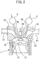
- FIG. 2 is a cross-sectional view of an engine body 1 of the internal combustion engine 100.
- the internal combustion engine 100 comprises an engine body 1 provided with a plurality of cylinders 10, a fuel feed system 2, an intake device 3, an exhaust device 4, an intake valve operating device 5, and an exhaust valve operating device 6.
- the engine body 1 makes fuel burn in a combustion chamber 11 formed in each cylinder 10 (see FIG. 2 ) to generate power for driving for example a vehicle etc.
- the engine body 1 is provided with a pair of intake valves 50 and a pair of exhaust valves 60 for each cylinder.
- the fuel feed system 2 is provided with electronic control type fuel injectors 20, a delivery pipe 21, supply pump 22, fuel tank 23, pressure pipe 24, and fuel pressure sensor 211.
- Each fuel injector 20 is provided at the engine body 1 so as to be able to inject fuel toward a cavity 13 formed at a top surface of a piston 12 receiving combustion pressure and moving reciprocally inside a cylinder 10 and thereby form a stratified premixed gas.
- one fuel injector 20 is provided at each cylinder 10 so as to face the combustion chamber 11 of the cylinder 10.
- the opening time (injection amount) and opening timing (injection timing) of the fuel injector 20 are changed by control signals from the electronic control unit 200. If the fuel injector 20 is opened, fuel is directly injected from the fuel injector 20 into the combustion chamber 11.
- the delivery pipe 21 is connected through a pumping pipe 24 to the fuel tank 23.
- a feed pump 22 is provided for pressurizing fuel stored in the fuel tank 23 and feeding it to the delivery pipe 21.
- the delivery pipe 21 temporarily stores the high pressure fuel pumped from the feed pump 22. If a fuel injector 20 is opened, the high pressure fuel stored in the delivery pipe 21 is directly injected from that fuel injector 20 to the inside of a combustion chamber 11.
- the feed pump 22 is configured to be able to be changed in discharge amount.
- the discharge amount of the feed pump 22 is changed by a control signal from the electronic control unit 200.
- the fuel pressure inside the delivery pipe 21, that is, the injection pressure of each fuel injector 20, is controlled.
- a fuel pressure sensor 211 is provided at the delivery pipe 21.
- the fuel pressure sensor 211 detects the fuel pressure inside the delivery pipe 21, that is, the pressure of the fuel injected from the fuel injectors 20 to the cylinders 10 (injection pressure).
- the intake device 3 is a device for guiding intake air to the inside of a combustion chamber 11 and is configured to be able to change the state of the intake air sucked into the combustion chamber 11 (intake pressure, intake temperature, amount of EGR (exhaust gas recirculation) gas).
- the intake system 3 is provided with an intake pipe 30 and intake manifold 31 forming an intake passage and an EGR passage 32.
- the intake passage 30 is connected at one end to an air cleaner 34 and is connected at the other end to an intake collector 31a of the intake manifold 31.
- an air flowmeter 212, compressor 71 of the exhaust turbocharger 7, intercooler 35, and throttle valve 36 are provided.
- the air flowmeter 212 detects the flow rate of air flowing through the inside of the intake passage 30 and finally being taken into a cylinder 10.
- the compressor 71 comprises a compressor housing 71a and a compressor wheel 71b arranged inside the compressor housing 71a.
- the compressor wheel 71b is driven to rotate by a turbine wheel 72b of the exhaust turbocharger 7 attached on the same shaft and compresses and discharges intake air flowing into the compressor housing 71a.
- a variable nozzle 72c for controlling the rotational speed of the turbine wheel 72b is provided. By using the variable nozzle 72c to control the rotational speed of the turbine wheel 72b, the pressure of the intake air discharged from inside the compressor housing 71a (supercharging pressure) is controlled.
- the intercooler 35 is a heat exchanger for cooling the intake air compressed by the compressor 71 and becoming a high temperature by, for example, running air or cooling water.
- the throttle valve 36 changes the cross-sectional area of the passage of the intake pipe 30 to thereby adjust the amount of intake introduced into the intake manifold 31.
- the throttle valve 36 is driven to operate by a throttle actuator 36a.
- the throttle sensor 213 detects its opening degree (throttle opening degree).
- the intake manifold 31 is connected to intake ports 14 formed in the engine body 1 and evenly distributes the intake flowing in from the intake pipe 30 through the intake ports 14 to the cylinders 10.
- the intake collector 31a of the intake manifold 31 is provided with an intake pressure sensor 214 for detecting the pressure of the intake air sucked into the cylinders (intake pressure) and an intake temperature sensor 215 for detecting the temperature of the intake air sucked into the cylinders (intake temperature).
- the EGR passage 32 is a passage for connecting the exhaust manifold 41 and intake collector 31a of the intake manifold 31 and returning part of the exhaust discharged from each cylinder 10 to the intake collector 31a by the pressure difference.
- the exhaust flowing into the EGR passage 32 will be called the "EGR gas”
- the ratio of the amount of EGR gas in the amount of gas in a cylinder, that is, the rate of reflux of the exhaust will be called the "EGR rate”.
- the EGR cooler 37 is a heat exchanger for cooling the EGR gas by, for example, running air or cooling water.
- the EGR valve 38 is a solenoid valve enabling continuous or stepwise adjustment of the opening degree.
- the opening degree is controlled by the electronic control unit 200 in accordance with the engine operating state. By controlling the opening degree of the EGR valve 38, the flow rate of the EGR gas recirculated to the intake collector 31a is adjusted.
- the exhaust device 4 is a device for discharging exhaust from the cylinders and is comprised of an exhaust manifold 41 and exhaust passage 42.
- the exhaust manifold 41 is connected to an exhaust port 15 formed at the engine body 1 and gathers together the exhaust discharged from the cylinders 10 for introduction into the exhaust passage 42.
- the turbine 72 of the exhaust turbocharger 7 and an exhaust post-treatment device 43 are provided.
- the turbine 72 is provided with a turbine housing 72a and a turbine wheel 72b arranged inside the turbine housing 72a.
- the turbine wheel 72b is driven to rotate by the energy of the exhaust flowing into the turbine housing 72a and drives a compressor wheel 71b attached on the same shaft.
- variable nozzle 72c At the outside of the turbine wheel 72b, the above-mentioned variable nozzle 72c is provided.
- the variable nozzle 72c functions as a throttle valve.
- the nozzle opening degree (valve opening degree) of the variable nozzle 72c is controlled by the electronic control unit 200.
- By changing the nozzle opening degree of the variable nozzle 72c it is possible to change the flow rate of exhaust driving the turbine wheel 72b inside the turbine housing 72a. That is, by changing the nozzle opening degree of the variable nozzle 72c, it is possible to change the rotational speed of the turbine wheel 72b to change the supercharging pressure. Specifically, if reducing the nozzle opening degree of the variable nozzle 72c (throttling the variable nozzle 72c), the flow rate of the exhaust rises, the rotational speed of the turbine wheel 72b increases, and the supercharging pressure increases.
- the exhaust post treatment device 43 is a device for cleaning the exhaust, then discharging it into the outside air and is provided with various types of exhaust purification catalysts for removing harmful substances, filters for trapping harmful substances, etc.
- the intake valve operating device 5 is a device for driving the intake valves 50 of the cylinders 10 to open and close and is provided at the engine body 1.
- the intake valve operating device 5 according to the present embodiment is configured to use for example an electromagnetic actuator to drive the intake valves 50 to open and close so as to enable control of the opening and closing timings of the intake valves 50.
- the disclosure is not limited to this. It is also possible to configure it to use an intake cam shaft to drive the intake valves 50 to open and close and provide a variable valve operating device for changing the relative phase angle of the intake cam shaft to the crankshaft by hydraulic control of one end of the intake cam shaft to thereby enable control of the opening/closing timings of the intake valves 50.
- the exhaust valve operating device 6 is a device for driving operation of the exhaust valve 60 of each cylinder 10 and is provided at the engine body 1.
- the exhaust valve operating device 6 according to the present embodiment is configured so as to make the exhaust valve 60 of the each cylinder 10 open during the exhaust stroke and to enable opening even during the intake stroke in accordance with need.
- an electromagnetic actuator controlled by the electronic control unit 200 is employed as such an exhaust valve operating device 6.
- the exhaust valve operating device 6 is not limited to an electromagnetic actuator.
- the electronic control unit 200 is comprised of a digital computer provided with components connected with each other by a bidirectional bus 201 such as a ROM (read only memory) 202, RAM (random access memory) 203, CPU (microprocessor) 204, input port 205, and output port 206.
- ROM read only memory
- RAM random access memory
- CPU microprocessor
- the input port 205 receives as input the output signals of the above-mentioned fuel pressure sensor 211 etc. through the corresponding AD converters 207. Further, the input port 205 receives as input, as a signal for detecting the engine load, the output voltage of a load sensor 217 generating an output voltage proportional to the amount of depression of the accelerator pedal 220 (below, referred to as "the amount of accelerator depression") through the corresponding AD converter 207. Further, the input port 205 receives as input, as a signal for calculating the engine rotational speed etc., the output signal of a crank angle sensor 218 generating an output pulse each time the crankshaft of the engine body 1 rotates for example by 15°. In this way, the input port 205 receives as input the output signals of various types of sensors required for control of the internal combustion engine 100.
- the output port 206 is connected to the fuel injectors 20 and other controlled parts through the corresponding drive circuits 208.
- the electronic control unit 200 outputs control signals for controlling the various controlled parts from the output port 206 to control the internal combustion engine 100 based on the output signals of the various types of sensors input to the input port 205. Below, the control of the internal combustion engine 100 performed by the electronic control unit 200 will be explained.
- the electronic control unit 200 operates the engine body 1 by switching the operating mode of the engine body 1 to the premix charged compressive ignition mode (below, referred to as the "PCCI” mode") or diffusive combustion mode (below, referred to as the "DC mode”) based on the engine operating state (engine rotational speed and engine load).
- PCCI premix charged compressive ignition mode
- DC mode diffusive combustion mode
- the electronic control unit 200 switches the operating mode to the PCCI mode if the engine operating state is the low speed, low load side PCCI region and switches the operating mode to the DC mode if the engine operating state is the high speed, high load side DC region. Further, the electronic control unit 200 operates the engine body 1 by controlling the various devices such as the fuel feed system 2 and intake device 3 in accordance with the operating mode.
- the electronic control unit 200 operates the engine body 1 by controlling the various devices so that when the operating mode is the DC mode, the fuel injected into a combustion chamber 11 basically burns with a short ignition delay time (time from when fuel is injected into the combustion chamber 11 to when the fuel self-ignites) with substantially no delay after fuel injection as diffusive combustion.
- the electronic control unit 200 operates the engine body 1 by controlling the various devices so that when the operating mode is the PCCI mode, the fuel injected into a combustion chamber 11 basically burns after a certain premixing time with the air after fuel injection (that is, ignition delay time longer than the time of diffusive combustion after fuel injection) as premix charged compressive ignition.
- diffusive combustion is a mode of combustion with a short premix type of fuel and air after fuel injection compared with premix charged compressive ignition, so the ratio of combustion of an air-fuel mixture greater in fuel concentration in a combustion chamber 11 (that is, air-fuel mixture with large equivalent ratio ⁇ ) tends to increase. If an air-fuel mixture with a high fuel concentration burns in the combustion chamber 11, the shortage of oxygen results in soot being produced and causing smoke.
- premix charged compressive ignition is a combustion mode providing a certain time period for premixing fuel and air after fuel injection and burning the premix.
- it is possible to reduce the ratio of combustion of an air-fuel mixture with a high fuel concentration in a combustion chamber 11.
- premix charged compressive ignition like in the present embodiment in an operating region enabling both premix charged compressive ignition and diffusive combustion, the production of soot can be suppressed, so the exhaust emission can be improved.
- FIG. 4 is a view showing the relationship between a crank angle and heat generation rate when performing compressive ignition by injecting fuel from the fuel injector 20 just once at any timing in the compression stroke.
- the "heat generation rate (dQ/d ⁇ )[J/°CA]" is the amount of heat per unit crank angle generated by burning the fuel, that is, the amount Q of heat generated per unit crank angle. Note that in the following explanation, the combustion waveform showing the relationship of the crank angle and heat generation rate will be referred to as the "heat generation rate pattern" according to need.
- the combustion noise D is correlated with the peak value and the slant at the start of combustion of this heat generation rate pattern.
- premix charged compressive ignition has the problem that it is difficult to control the self-ignition timing to the target self-ignition timing compared with when performing diffusive combustion. If the self-ignition timing deviates from the target self-ignition timing, various problems arise.
- the premixes burn by self-ignition by a crank angle in the expansion stroke at the advanced side closer to compression top dead center than usual, that is, a crank angle higher in cylinder pressure P and cylinder temperature T than usual.
- the combustion becomes more vigorous than usual, the combustion speed increases, and as a result the problem arises that the peak value and slant at the start of combustion of the heat generation rate become greater than usual and the combustion noise increases from usual.
- the self-ignition timing becomes delayed from the target self-ignition timing, conversely the combustion becomes slower and the combustion ends up with a low constant volume degree. As a result, the problem arises that the output falls and torque fluctuation occurs.
- the operating mode is the PCCI mode
- fuel is injected divided to cause a plurality of compressive ignitions in stages with a time difference so as to make the heat generation rate pattern when performing the premix charged compressive ignition a heat generation rate pattern where the combustion noise becomes smaller and precisely control the self-ignition timing to the target self-ignition timing.
- at least two auxiliary fuel injections of a first pre-injection G1 and second pre-injection G2 are performed before a main injection GM as main fuel injection mainly for causing the generation of the required torque.
- FIG. 5 is a view showing the relationship between the crank angle and heat generation rate when controlling combustion at the time of the PCCI mode according to the present embodiment. Specifically, it is a view showing the relationship between the crank angle and heat generation rate when sequentially performing the first pre-injection G1, second pre-injection G2, and main injection GM from the fuel injector 20 without changing the total of the fuel injection amounts compared with the case of FIG. 4 and causing compressive ignition three times in stages with provision of a time difference.
- the heat generation rate pattern A is the heat generation rate pattern when a premix formed by mainly the first pre-injection G1 is burned by compressive ignition.
- the heat generation rate pattern B is the heat generation rate pattern when a premix formed by mainly the second pre-injection G2 is burned by compressive ignition.
- the heat generation rate pattern C is the heat generation rate pattern when a premix formed by mainly the main injection GM is burned by compressive ignition.
- the heat generation rate pattern D is the actual heat generation rate pattern combining the heat generation rate pattern A, heat generation rate pattern B, and heat generation rate pattern C.
- the heat generation rate pattern E is the heat generation rate pattern of FIG. 4 shown for comparison.
- the crank angle where the tangent at the location where the slant of the heat generation rate pattern D becomes maximum (in the example of FIG. 5 , the point P1) and the abscissa (in the example of FIG. 5 , the point P0) is defined as the self-ignition timing of the premix formed by the main injection GM (below, referred to as the "main self-ignition timing").
- the target injection timing of the main injection is set based on the engine operating state so that the main self-ignition timing becomes the target main self-ignition timing. Note that, in the present embodiment, experiments etc. are run in advance to set the target main self-ignition timing so that the constant volume degree becomes a predetermined value or more.
- the target injection amounts and target injection timings of the first pre-injection G1 and second pre-injection G2 are set so that no clear heat generation is caused before the start of the main injection GM.
- the target injection amounts and target injection timings of the first pre-injection G1 and second pre-injection G2 are set so that the premixes formed by the first pre-injection G1 and the second pre-injection G2 do not burn before the start of the main injection GM.
- the target injection amounts and target injection timings of the first pre-injection G1 and the second pre-injection G2 are set so that at least after the main injection GM is started, the premix formed by the first pre-injection G1 first self-ignites, then the premix formed by the second pre-injection G2 self-ignites, and finally the premix formed by the main injection GM self-ignites.
- the target injection amounts and target injection timings of the first pre-injection G1 and the second pre-injection G2 are set so that the premixes formed by the injections start to burn by compressive ignition in stages.
- the peak value of the actual combustion waveform combining the heat generation rate pattern A, heat generation rate pattern B, and heat generation rate pattern C, that is, the heat generation rate pattern D, can be lowered from the peak value of the heat generation rate pattern E and a heat generation rate pattern with smaller combustion noise can be formed.
- the first pre-injection G1 and the second pre-injection G2 can be performed by the following such technical idea so as to form a heat generation rate pattern with a further smaller combustion noise and the main self-ignition timing can be precisely controlled to the target main self-ignition timing.
- the first pre-injection G1 and second pre-injection G2 will be explained.
- the first pre-injection G1 is injection performed for reducing the combustion noise when performing premix charged compressive ignition.
- the target injection amount A1 and target injection timing W1 of the first pre-injection G1 are set so that the peak value and slant at the start of combustion in the heat generation rate pattern A when the premix formed by the first pre-injection G1 burns by compressive ignition become smaller than the peak values and slants at the start of combustion of the heat generation rate patterns B and C when the premixes formed by the second pre-injection G2 and main injection GM burn by compressive ignition.
- the target injection amount A1 and target injection timing W1 of the first pre-injection G1 are set so that the premix formed by the first pre-injection G1 first burns by compressive ignition after becoming a lean premix with an equivalent ratio ⁇ of less than about 1.
- the value of the equivalent ratio ⁇ of the premix formed by the fuel injected from the fuel injector 20, if the fuel injection amount is the same basically depends on elapsed time from when fuel is injected regardless of the engine operating state. That is, the value of the equivalent ratio ⁇ of the premix formed by the fuel injected from the fuel injector 20, if the fuel injection amount is the same, basically becomes a value corresponding to the elapsed time from when fuel is injected regardless of the engine operating state. The longer the elapsed time from injection of fuel, the more the fuel is dispersed along with the elapse of time, so the smaller the value becomes.
- the target injection timing W1 of the first pre-injection G1 is set based on target injection amount A1 of the first pre-injection G1 and the engine rotational speed so that the time from the first pre-injection G1 to the target main self-ignition timing becomes a first premixing time determined corresponding to the target injection amount A1 of the first pre-injection G1 based on the target main self-ignition timing. Due to this, the premix formed by the first pre-injection G1 first burns by compressive ignition after the premix becomes a lean premix with an equivalent ratio ⁇ of roughly less than 1.
- the second pre-injection G2 is injection performed for precisely controlling the main self-ignition timing to the target main self-ignition timing. For this reason, in the present embodiment, the target injection amount A2 and target injection timing W2 of the second pre-injection G2 are set so that the premix formed by the second pre-injection G2 ignites after the premix formed by the first pre-injection G1 starts to self-ignite and before the premix formed by the main injection GM.
- the second pre-injection G2 is performed so that it self-ignites before the premix formed by the main injection GM and the heat of combustion when burning the premix formed by the second pre-injection G2 is used to cause compressive ignition of the premix formed by the main injection GM.
- the target injection amount A2 and target injection timing W2 of the second pre-injection G2 are set so that the premix formed by the second pre-injection G2 self-ignites when becoming a rich premix with an equivalent ratio ⁇ of roughly 1 to 2 or so. Below, the reasons will be explained.
- FIG. 6 is a view showing the relationship between the equivalent ratio ⁇ and the ignition delay time ⁇ in accordance with the oxygen concentration in a combustion chamber 11.
- the ignition delay time ⁇ becomes the shortest when the equivalent ratio ⁇ of the premix is about 1.5. Further, the ignition delay time ⁇ increases in length as the equivalent ratio ⁇ becomes smaller than 1.5 and greatly increases in length if the equivalent ratio ⁇ becomes smaller than 1 since the premix becomes lean and harder to ignite. Further, if the equivalent ratio ⁇ becomes smaller than 1, the ignition delay time ⁇ greatly changes due to differences in the oxygen concentration.
- the ignition delay time ⁇ becomes longer since even if the equivalent ratio ⁇ becomes larger than 1.5, the cylinder temperature easily falls due to the latent heat of evaporation of fuel, so the premix becomes harder to self-ignite.
- the equivalent ratio ⁇ is larger than 1.5, there is little change of the ignition delay time ⁇ due to the differences in oxygen concentration.
- the equivalent ratio ⁇ of the premix is roughly 1 to 2
- the ignition delay time ⁇ becomes relatively short and there is also little change in the ignition delay time ⁇ due to differences in the oxygen concentration.
- the second pre-injection G2 to form a premix with an equivalent ratio ⁇ of roughly 1 to 2 or so and making this premix self-ignite before the premix formed by the main injection GM, not only at the time of a steady state, but also the time of a transient state, it is possible to stabilize the self-ignition timing of the premix formed by the second pre-injection G2.
- ⁇ roughly 1 to 2 or so
- the target injection timing W2 of the second pre-injection G2 is set based on the target injection amount A2 of the second pre-injection G1 and the engine rotational speed so that the time from the second pre-injection G1 to the target main self-ignition timing becomes a second premixing time determined corresponding to the target injection amount A2 of the second pre-injection G2 ( ⁇ first premixing time) based on the target main self-ignition timing. Due to this, self-ignition is caused after the premix formed by the second pre-injection G2 becomes a premix with an equivalent ratio ⁇ of roughly 1 to 2 or so.
- the second pre-injection G2 is performed in the state where the the cylinder temperature T and cylinder pressure P are higher than the first pre-injection G1.
- the premix formed by the second pre-injection G2 is a premix richer than the premix formed by the first pre-injection G1. For this reason, the ignition delay time ⁇ of the premix formed by the second pre-injection G2 tends to become shorter compared with the ignition delay time ⁇ of the premix formed by the first pre-injection G1.
- the injection timing of the second pre-injection G2 definitely has to be made to approach the injection timing of the main injection GM.
- the first pre-injection G1 is performed in the state where the cylinder temperature T and cylinder pressure P are low. Further, the premix formed by the first pre-injection G2 is a lean premix. For this reason, the ignition delay time ⁇ of the premix formed by the first pre-injection G1 tends to conversely become longer compared with the ignition delay time ⁇ of the premix formed by the second pre-injection G2. Therefore, when making the premix formed by the first pre-injection G1 first burn by self-ignition after performing the main injection GM, the injection timing of the second pre-injection G1 definitely must be made far from the injection timing of the main injection GM.
- the crank interval from the first pre-injection G1 to the second injection G2 becomes larger than the crank interval from the second injection G2 to the main injection GM.
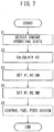
- FIG. 7 is a flow chart explaining the fuel injection control at the time of the PCCI mode according to the present embodiment.
- the electronic control unit 200 repeatedly performs the present routine by a predetermined processing period (for example, 10 ms) when the operating mode is set to the PCCI mode.
- the electronic control unit 200 reads the engine rotational speed calculated based on the output signal of the crank angle sensor 218 and the engine load detected by the load sensor 217 and detects the engine operating state.
- the electronic control unit 200 refers to a table prepared in advance by experiments etc. and calculates the overall fuel injection amount AT based on the engine load.
- the overall fuel injection amount AT becomes larger the higher the engine load.
- the electronic control unit 200 sets the target injection amounts of the first pre-injection G1, second pre-injection G2, and main injection GM.
- the electronic control unit 200 sets the target injection amount of the main injection GM at a preset predetermined target injection amount AM regardless of the engine load. Further, the electronic control unit 200 divides the remaining injection amount A0, obtained by subtracting the target injection amount AM of the main injection GM from the overall fuel injection amount AT, between the target injection amount A1 of the first pre-injection G1 and the target injection amount A2 of the second pre-injection G2.
- the electronic control unit 200 divides the remaining injection amount A0, obtained by subtracting the target injection amount AM of the main injection GM from the overall fuel injection amount AT, by a distribution rate corresponding to the engine load to set the target injection amount A1 of the first pre-injection G1 and the target injection amount A2 of the second pre-injection G2.
- the electronic control unit 200 divides the injection amount A0 between the target injection amount A1 and the target injection amount A2 so that the ratio of the target injection amount A1 with respect to the injection amount A0 becomes higher than the ratio of the target injection amount A2 with respect to the injection amount A0 the higher the engine load so as to calculate the target injection amount A1 of the first pre-injection G1 and the target injection amount A2 of the second pre-injection G2.
- the ratio of increase of the target injection amount A1 of the first pre-injection G1 is made larger than the ratio of increase of the target injection amount A2 of the second pre-injection G2.
- the ratio of increase of the target injection amount A1 of the first pre-injection G1 contributing to the formation of the heat generation rate pattern A with the smallest peak value of the heat generation rate pattern, it is possible to suppress the increase in the peak value of the actual combustion waveform of the heat generation rate pattern D. For this reason, it is possible to further suppress combustion noise when the engine load becomes high and the overall fuel injection amount AT increases.
- the electronic control unit 200 sets the target injection timings of the first pre-injection G1, second pre-injection G2, and main injection GM.
- the electronic control unit 200 refers to a map prepared in advance and sets the target injection timing WM of the main injection GM based on the engine operating state so that the main self-ignition timing becomes the target main self-ignition timing.
- the electronic control unit 200 sets the target injection timing W1 of the first pre-injection G1 and target injection timing W2 of the second pre-injection G2 as follows:
- a certain time corresponding to the target injection amount A1 becomes necessary after the first pre-injection G1 is performed. This certain time becomes longer the greater the target injection amount A1. Further, to secure the certain time for the premixing, the higher the engine rotational speed, the more to the advanced side the first pre-injection G1 must be performed compared with when it is low.
- the electronic control unit 200 sets the target injection timing W1 of the first pre-injection G1 based on the target injection amount A1 of the first pre-injection G1 and the engine rotational speed so that the time from the first pre-injection G1 to the target main self-ignition timing becomes a predetermined first premixing time or more corresponding to the target injection amount A1.
- the first premixing time becomes longer the greater the target injection amount A1.
- the time after performing the second pre-injection G2 to when the premix formed by the second pre-injection G2 burns by compressive ignition has to be made within the range of a certain time corresponding to the target injection amount of the second pre-injection G2. That certain time becomes longer the greater the target injection amount A2. Further, to secure that certain time, the higher the engine rotational speed, the more to the advanced side the second pre-injection G2 must be performed compared to when it is low.
- the electronic control unit 200 sets the target injection timing W2 of the second pre-injection G2 based on the target injection amount A2 of the second pre-injection G2 and engine rotational speed so that the time from the second pre-injection G2 to the target main self-ignition timing becomes a predetermined second premixing time corresponding to the target injection amount A2.
- the second premixing time becomes a time shorter than the first premixing time.
- the electronic control unit 200 controls the fuel feed system 2 so that the target injection amount A1 of fuel is injected at the target injection timing W1 of the first pre-injection G1. Further, the electronic control unit 200 controls the fuel feed system 2 so that the target injection amount A2 of fuel is injected at the target injection timing W2 of the second pre-injection G2. Still further, the electronic control unit 200 controls the fuel feed system 2 so that the target injection amount AM of fuel is injected at the target injection timing WM of the main pre-injection GM.
- an electronic control unit 200 for controlling an internal combustion engine 100 provided with an engine body 1 and fuel injectors injecting fuel into combustion chambers 11 of the engine body 1.
- a combustion control part sequentially injecting from a fuel injector at least primary auxiliary fuel (fuel injected by first pre-injection G1), secondary auxiliary fuel (fuel injected by second pre-injection G2), and main fuel (fuel injected by main injection GM) in predetermined operating regions, sequentially causing compressive ignition from the premix containing the primary auxiliary fuel after injecting the main fuel, and causing compressive ignition of the premix containing the main fuel using the heat when making the premix containing the secondary auxiliary fuel burn by compressive ignition.
- the combustion control part is configured to set the target injection amount A1 and target injection timing W1 of the primary auxiliary fuel so that the peak value and slant at the start of combustion of the heat generation rate pattern A formed by the premix containing the primary auxiliary fuel become smaller than the peak values and slants at the start of combustion of the heat generation rate patterns B and C formed by the premixes containing the secondary auxiliary fuel and main fuel.
- the combustion control part is configured to set the target injection amount and target injection timing of the primary auxiliary fuel so that the premix containing the primary auxiliary fuel first burns by compressive ignition after becoming a premix with an equivalent ratio of less than 1.
- the premix containing the primary auxiliary fuel first burn by compressive ignition after becoming a premix with an equivalent ratio of less than 1, the following effects are also exhibited. That is, an air-fuel mixture with an equivalent ratio of less than 1 varies in self-ignition timing due to differences in the oxygen concentration, but primary auxiliary fuel is fuel contributing to the formation of a heat generation rate pattern A with the smallest peak value of the heat generation rate pattern, so even if the self-ignition timing varies and the peak value and slant at the start of combustion of the heat generation rate pattern A becomes larger, it is possible to suppress any change in the peak value of the actual combustion waveform of the heat generation rate pattern D. Therefore, it is possible to suppress an increase in the combustion noise at the time of a transient state.
- combustion control part is configured to be further provided with a first auxiliary fuel injection timing setting part setting the target injection timing W1 of the primary auxiliary fuel based on the target injection amount A1 and engine rotational speed of the primary auxiliary fuel so that the time from the target injection timing W1 of the primary auxiliary fuel to the self-ignition timing of the main fuel becomes the first premixing time corresponding to the target injection amount A1 of the primary auxiliary fuel regardless of the engine rotational speed.
- the combustion control part is further provided with an overall fuel injection amount setting part setting an overall fuel injection amount AT based on the engine load and a distribution part distributing a remaining injection amount A0, obtained by subtracting the preset target injection amount Am of the main fuel from the overall fuel injection amount AT, between the target injection amount A1 of the primary auxiliary fuel and the target injection amount A2 of the secondary auxiliary fuel.
- the overall fuel injection amount setting part increases the overall fuel injection amount AT when the engine load is high compared to when it is low, while the distribution part is configured to raise the ratio of target injection amount A1 of the primary auxiliary fuel with respect to the remaining fuel amount A0 when the engine load is high compared with when it is low.
- combustion control part is configured to set the target injection amount A2 and target injection timing W2 of the secondary auxiliary fuel so that the premix containing the secondary auxiliary fuel burns by compressive ignition when equivalent ratio of the premix containing the secondary auxiliary fuel is 1 to 2 after the premix containing the primary auxiliary fuel starts to burn by compressive ignition.
- the combustion control part is configured to be further provided with a second auxiliary fuel injection timing setting part setting a target injection timing W2 of the secondary auxiliary fuel based on the target injection amount A2 of the secondary auxiliary fuel and engine rotational speed so that regardless of the engine rotational speed, the time from the target injection timing W2 of the secondary auxiliary fuel to the self-ignition timing of the main fuel becomes a predetermined second premixing time shorter than the first premixing time.
- the second pre-injection G2 to form a premix with an equivalent ratio ⁇ of roughly 1 to 2 or so and making this premix self-ignite before the premix formed by the main injection GM, it is possible to stabilize the self-ignition timing of the premix formed by the second pre-injection G2 not only at the time of a steady state, but also the time of a transient state. As a result, it is possible to stabilize the self-ignition timing of the premix formed by the main injection GM, so it is possible to precisely control the main self-ignition timing to the target main self-ignition timing.
- the interval from the crank angle corresponding to the injection timing of the primary auxiliary fuel to the crank angle corresponding to the injection timing of the secondary fuel becomes larger than the interval from the crank angle corresponding to the injection timing of the secondary fuel to the crank angle corresponding to the injection timing of the main fuel. Due to this, it is possible to make the premixes formed by injections after injecting the fuel divided self-ignite in stages after performing the main injection GM.
- the target injection timing W1 of the first pre-injection G1 was strictly set based on the target injection amount A1 and the engine rotational speed so as to make the premix formed by the first pre-injection G1 self-ignite after being made a lean premix with an equivalent ratio ⁇ of roughly less than 1. If providing a certain constant time or more of time for premixing, the premix formed by the first pre-injection G1 can be made a lean premix with an equivalent ratio ⁇ of roughly less than 1 regardless of the target injection amount A1. Therefore, the target injection timing W1 of the first pre-injection G1 may also be set based on the engine rotational speed regardless of the target injection amount A1. Further, target injection timing W2 of the second pre-injection G2 may similarly be set based on the engine rotational speed regardless of the target injection amount A2.
Landscapes
- Engineering & Computer Science (AREA)
- Chemical & Material Sciences (AREA)
- Combustion & Propulsion (AREA)
- Mechanical Engineering (AREA)
- General Engineering & Computer Science (AREA)
- Electrical Control Of Air Or Fuel Supplied To Internal-Combustion Engine (AREA)
- Combustion Methods Of Internal-Combustion Engines (AREA)
Applications Claiming Priority (1)
| Application Number | Priority Date | Filing Date | Title |
|---|---|---|---|
| JP2016249850A JP6508186B2 (ja) | 2016-12-22 | 2016-12-22 | 内燃機関の制御装置 |
Publications (2)
| Publication Number | Publication Date |
|---|---|
| EP3339616A1 true EP3339616A1 (de) | 2018-06-27 |
| EP3339616B1 EP3339616B1 (de) | 2020-02-19 |
Family
ID=60702350
Family Applications (1)
| Application Number | Title | Priority Date | Filing Date |
|---|---|---|---|
| EP17208881.7A Active EP3339616B1 (de) | 2016-12-22 | 2017-12-20 | Steuerungsvorrichtung für verbrennungsmotor |
Country Status (4)
| Country | Link |
|---|---|
| US (1) | US10309325B2 (de) |
| EP (1) | EP3339616B1 (de) |
| JP (1) | JP6508186B2 (de) |
| CN (1) | CN108223178B (de) |
Cited By (2)
| Publication number | Priority date | Publication date | Assignee | Title |
|---|---|---|---|---|
| WO2020007456A1 (en) * | 2018-07-04 | 2020-01-09 | Wärtsilä Finland Oy | Method of increasing load in a four stoke internal combustion engine |
| EP3674533A1 (de) * | 2018-12-25 | 2020-07-01 | Mazda Motor Corporation | Steuervorrichtung für kompressionszündungsmotor, kompressionszündungsmotor, fahrzeug, verfahren zur steuerung eines kompressionszündungsmotors und computerprogrammprodukt |
Families Citing this family (3)
| Publication number | Priority date | Publication date | Assignee | Title |
|---|---|---|---|---|
| JP7225593B2 (ja) * | 2018-07-26 | 2023-02-21 | マツダ株式会社 | 圧縮着火式エンジンの制御装置 |
| DE102018219028B4 (de) * | 2018-11-08 | 2020-06-25 | Continental Automotive Gmbh | Verfahren zum Betreiben eines Verbrennungsmotors mit Durchführung einer Einspritzmengenkorrektur |
| CN116981841A (zh) * | 2021-04-19 | 2023-10-31 | 日立安斯泰莫株式会社 | 内燃机的控制装置 |
Citations (3)
| Publication number | Priority date | Publication date | Assignee | Title |
|---|---|---|---|---|
| JP2012062880A (ja) | 2010-08-20 | 2012-03-29 | Mazda Motor Corp | ディーゼルエンジンの制御装置及びディーゼルエンジンの制御方法 |
| US20130073186A1 (en) * | 2010-05-11 | 2013-03-21 | Mazda Motor Corporation | Diesel engine for automobile, control device and control method |
| JP2016180326A (ja) * | 2015-03-23 | 2016-10-13 | マツダ株式会社 | 直噴エンジンの燃料噴射制御装置 |
Family Cites Families (21)
| Publication number | Priority date | Publication date | Assignee | Title |
|---|---|---|---|---|
| JPH10141124A (ja) * | 1996-11-07 | 1998-05-26 | Hino Motors Ltd | ディーゼルエンジン |
| JP3911912B2 (ja) | 1999-06-23 | 2007-05-09 | 株式会社日立製作所 | エンジン制御システム及び制御方法 |
| JP3879672B2 (ja) | 2002-03-28 | 2007-02-14 | マツダ株式会社 | エンジンの燃焼制御装置 |
| US6964256B2 (en) | 2002-03-28 | 2005-11-15 | Mazda Motor Corporation | Combustion control apparatus for an engine |
| ATE426739T1 (de) * | 2004-06-15 | 2009-04-15 | Fiat Ricerche | Regelungssystem zur regelung der verbrennung in einem dieselmotor mit vorgemischter verbrennung |
| JP2007332858A (ja) | 2006-06-15 | 2007-12-27 | Honda Motor Co Ltd | 内燃機関の燃料噴射制御装置 |
| EP1903204A1 (de) * | 2006-09-12 | 2008-03-26 | Siemens Aktiengesellschaft | Verfahren zur Reduzierung der Abgasemissionen und des Verbrauchs eines Motors |
| DE102008000916B4 (de) * | 2007-04-02 | 2021-12-16 | Denso Corporation | Verbrennungssteuerungsvorrichtung für direkt einspritzende Kompressionszündungskraftmaschine |
| CN102165171A (zh) * | 2008-09-29 | 2011-08-24 | 丰田自动车株式会社 | 内燃机的燃料喷射控制装置 |
| JP5263532B2 (ja) | 2009-03-31 | 2013-08-14 | マツダ株式会社 | ディーゼルエンジンの燃焼制御装置及び燃焼制御方法 |
| JP5040951B2 (ja) * | 2009-03-31 | 2012-10-03 | マツダ株式会社 | 直噴エンジンの制御方法および直噴エンジン |
| JP4848024B2 (ja) * | 2009-04-21 | 2011-12-28 | 本田技研工業株式会社 | 内燃機関の制御装置 |
| JP5229185B2 (ja) * | 2009-10-21 | 2013-07-03 | トヨタ自動車株式会社 | 内燃機関の燃焼制御装置 |
| JP5062340B2 (ja) * | 2011-03-11 | 2012-10-31 | 株式会社豊田自動織機 | 燃料噴射装置 |
| CN105247204B (zh) * | 2013-05-31 | 2017-12-19 | 丰田自动车株式会社 | 内燃机的控制系统 |
| US20150053171A1 (en) * | 2013-08-23 | 2015-02-26 | Transonic Combustion, Inc. | Internal combustion engine with high temperature fuel injection |
| JP5873059B2 (ja) * | 2013-09-30 | 2016-03-01 | 株式会社豊田中央研究所 | 圧縮着火式内燃機関 |
| JP5979126B2 (ja) * | 2013-12-12 | 2016-08-24 | トヨタ自動車株式会社 | 機関制御装置 |
| JP6358007B2 (ja) * | 2014-09-19 | 2018-07-18 | スズキ株式会社 | 内燃機関の制御装置 |
| JP6500921B2 (ja) * | 2017-01-19 | 2019-04-17 | トヨタ自動車株式会社 | 内燃機関の制御装置 |
| JP6622251B2 (ja) * | 2017-06-02 | 2019-12-18 | トヨタ自動車株式会社 | 内燃機関の制御装置 |
-
2016
- 2016-12-22 JP JP2016249850A patent/JP6508186B2/ja active Active
-
2017
- 2017-12-20 EP EP17208881.7A patent/EP3339616B1/de active Active
- 2017-12-20 CN CN201711381047.7A patent/CN108223178B/zh not_active Expired - Fee Related
- 2017-12-21 US US15/849,802 patent/US10309325B2/en active Active
Patent Citations (4)
| Publication number | Priority date | Publication date | Assignee | Title |
|---|---|---|---|---|
| US20130073186A1 (en) * | 2010-05-11 | 2013-03-21 | Mazda Motor Corporation | Diesel engine for automobile, control device and control method |
| JP2012062880A (ja) | 2010-08-20 | 2012-03-29 | Mazda Motor Corp | ディーゼルエンジンの制御装置及びディーゼルエンジンの制御方法 |
| JP2016180326A (ja) * | 2015-03-23 | 2016-10-13 | マツダ株式会社 | 直噴エンジンの燃料噴射制御装置 |
| US20180066600A1 (en) * | 2015-03-23 | 2018-03-08 | Mazda Motor Corporation | Fuel injection control device for direct-injection engine |
Cited By (5)
| Publication number | Priority date | Publication date | Assignee | Title |
|---|---|---|---|---|
| WO2020007456A1 (en) * | 2018-07-04 | 2020-01-09 | Wärtsilä Finland Oy | Method of increasing load in a four stoke internal combustion engine |
| CN112368470A (zh) * | 2018-07-04 | 2021-02-12 | 瓦锡兰芬兰有限公司 | 增加四冲程内燃发动机中的负荷的方法 |
| KR20210016475A (ko) * | 2018-07-04 | 2021-02-15 | 바르실라 핀랜드 오이 | 4행정 내연 기관에서 부하를 증가시키는 방법 |
| CN112368470B (zh) * | 2018-07-04 | 2023-03-10 | 瓦锡兰芬兰有限公司 | 增加四冲程内燃发动机中的负荷的方法 |
| EP3674533A1 (de) * | 2018-12-25 | 2020-07-01 | Mazda Motor Corporation | Steuervorrichtung für kompressionszündungsmotor, kompressionszündungsmotor, fahrzeug, verfahren zur steuerung eines kompressionszündungsmotors und computerprogrammprodukt |
Also Published As
| Publication number | Publication date |
|---|---|
| JP6508186B2 (ja) | 2019-05-08 |
| CN108223178A (zh) | 2018-06-29 |
| US10309325B2 (en) | 2019-06-04 |
| US20180179968A1 (en) | 2018-06-28 |
| JP2018105150A (ja) | 2018-07-05 |
| EP3339616B1 (de) | 2020-02-19 |
| CN108223178B (zh) | 2021-08-31 |
Similar Documents
| Publication | Publication Date | Title |
|---|---|---|
| US10138825B2 (en) | Control system for internal combustion engine, internal combustion engine and method of controlling internal combustion engine | |
| US10539098B2 (en) | Control system of compression-ignition engine | |
| EP3339616B1 (de) | Steuerungsvorrichtung für verbrennungsmotor | |
| EP2225450B1 (de) | Kraftstoffeinspritzsteuervorrichtung für einen verbrennungsmotor | |
| US20170292462A1 (en) | Control system for internal combustion engine | |
| EP3553301B1 (de) | Steuerungsvorrichtung für verbrennungsmotor | |
| US10247156B2 (en) | Internal combustion engine | |
| EP2274512B1 (de) | Kraftstoffeinspritzsteuergerät für verbrennungsmotoren | |
| JP5494205B2 (ja) | 自動車搭載用ディーゼルエンジン | |
| US10309334B2 (en) | Control device of internal combustion engine | |
| US10337446B2 (en) | Control device for internal combustion engine | |
| KR101973893B1 (ko) | 내연 기관의 제어 장치 | |
| RU2629560C1 (ru) | Устройство управления двигателем | |
| JP5626120B2 (ja) | エンジンの制御装置 | |
| JP2018040263A (ja) | 内燃機関の制御装置 | |
| JP2018040264A (ja) | 内燃機関の制御装置 | |
| EP3561275B1 (de) | Steuerungsvorrichtung für verbrennungsmotor | |
| JP6915577B2 (ja) | 内燃機関の制御装置 | |
| JP2013002378A (ja) | 内燃機関 | |
| JP2008196387A (ja) | 筒内噴射型内燃機関の制御装置 | |
| JP2003343332A (ja) | ディーゼルエンジンの燃料噴射制御装置 | |
| JP2021017811A (ja) | エンジンの制御装置 | |
| JP2018115625A (ja) | 内燃機関の制御装置 | |
| JP2019152106A (ja) | 内燃機関の制御装置 | |
| JP2018184903A (ja) | 内燃機関の制御装置 |
Legal Events
| Date | Code | Title | Description |
|---|---|---|---|
| PUAI | Public reference made under article 153(3) epc to a published international application that has entered the european phase |
Free format text: ORIGINAL CODE: 0009012 |
|
| STAA | Information on the status of an ep patent application or granted ep patent |
Free format text: STATUS: REQUEST FOR EXAMINATION WAS MADE |
|
| 17P | Request for examination filed |
Effective date: 20171220 |
|
| AK | Designated contracting states |
Kind code of ref document: A1 Designated state(s): AL AT BE BG CH CY CZ DE DK EE ES FI FR GB GR HR HU IE IS IT LI LT LU LV MC MK MT NL NO PL PT RO RS SE SI SK SM TR |
|
| AX | Request for extension of the european patent |
Extension state: BA ME |
|
| RIC1 | Information provided on ipc code assigned before grant |
Ipc: F02D 35/02 20060101ALI20190430BHEP Ipc: F02B 9/02 20060101ALI20190430BHEP Ipc: F02D 41/00 20060101ALI20190430BHEP Ipc: F02D 41/40 20060101ALI20190430BHEP Ipc: F02D 41/30 20060101AFI20190430BHEP |
|
| GRAP | Despatch of communication of intention to grant a patent |
Free format text: ORIGINAL CODE: EPIDOSNIGR1 |
|
| STAA | Information on the status of an ep patent application or granted ep patent |
Free format text: STATUS: GRANT OF PATENT IS INTENDED |
|
| INTG | Intention to grant announced |
Effective date: 20191129 |
|
| RIN1 | Information on inventor provided before grant (corrected) |
Inventor name: SHIMIZU, HAJIME |
|
| INTG | Intention to grant announced |
Effective date: 20191202 |
|
| GRAS | Grant fee paid |
Free format text: ORIGINAL CODE: EPIDOSNIGR3 |
|
| GRAA | (expected) grant |
Free format text: ORIGINAL CODE: 0009210 |
|
| STAA | Information on the status of an ep patent application or granted ep patent |
Free format text: STATUS: THE PATENT HAS BEEN GRANTED |
|
| AK | Designated contracting states |
Kind code of ref document: B1 Designated state(s): AL AT BE BG CH CY CZ DE DK EE ES FI FR GB GR HR HU IE IS IT LI LT LU LV MC MK MT NL NO PL PT RO RS SE SI SK SM TR |
|
| REG | Reference to a national code |
Ref country code: CH Ref legal event code: EP |
|
| REG | Reference to a national code |
Ref country code: DE Ref legal event code: R096 Ref document number: 602017011947 Country of ref document: DE |
|
| REG | Reference to a national code |
Ref country code: AT Ref legal event code: REF Ref document number: 1235241 Country of ref document: AT Kind code of ref document: T Effective date: 20200315 |
|
| REG | Reference to a national code |
Ref country code: IE Ref legal event code: FG4D |
|
| REG | Reference to a national code |
Ref country code: NL Ref legal event code: MP Effective date: 20200219 |
|
| PG25 | Lapsed in a contracting state [announced via postgrant information from national office to epo] |
Ref country code: RS Free format text: LAPSE BECAUSE OF FAILURE TO SUBMIT A TRANSLATION OF THE DESCRIPTION OR TO PAY THE FEE WITHIN THE PRESCRIBED TIME-LIMIT Effective date: 20200219 Ref country code: FI Free format text: LAPSE BECAUSE OF FAILURE TO SUBMIT A TRANSLATION OF THE DESCRIPTION OR TO PAY THE FEE WITHIN THE PRESCRIBED TIME-LIMIT Effective date: 20200219 Ref country code: NO Free format text: LAPSE BECAUSE OF FAILURE TO SUBMIT A TRANSLATION OF THE DESCRIPTION OR TO PAY THE FEE WITHIN THE PRESCRIBED TIME-LIMIT Effective date: 20200519 |
|
| REG | Reference to a national code |
Ref country code: LT Ref legal event code: MG4D |
|
| PG25 | Lapsed in a contracting state [announced via postgrant information from national office to epo] |
Ref country code: BG Free format text: LAPSE BECAUSE OF FAILURE TO SUBMIT A TRANSLATION OF THE DESCRIPTION OR TO PAY THE FEE WITHIN THE PRESCRIBED TIME-LIMIT Effective date: 20200519 Ref country code: IS Free format text: LAPSE BECAUSE OF FAILURE TO SUBMIT A TRANSLATION OF THE DESCRIPTION OR TO PAY THE FEE WITHIN THE PRESCRIBED TIME-LIMIT Effective date: 20200619 Ref country code: LV Free format text: LAPSE BECAUSE OF FAILURE TO SUBMIT A TRANSLATION OF THE DESCRIPTION OR TO PAY THE FEE WITHIN THE PRESCRIBED TIME-LIMIT Effective date: 20200219 Ref country code: SE Free format text: LAPSE BECAUSE OF FAILURE TO SUBMIT A TRANSLATION OF THE DESCRIPTION OR TO PAY THE FEE WITHIN THE PRESCRIBED TIME-LIMIT Effective date: 20200219 Ref country code: HR Free format text: LAPSE BECAUSE OF FAILURE TO SUBMIT A TRANSLATION OF THE DESCRIPTION OR TO PAY THE FEE WITHIN THE PRESCRIBED TIME-LIMIT Effective date: 20200219 Ref country code: GR Free format text: LAPSE BECAUSE OF FAILURE TO SUBMIT A TRANSLATION OF THE DESCRIPTION OR TO PAY THE FEE WITHIN THE PRESCRIBED TIME-LIMIT Effective date: 20200520 |
|
| PG25 | Lapsed in a contracting state [announced via postgrant information from national office to epo] |
Ref country code: NL Free format text: LAPSE BECAUSE OF FAILURE TO SUBMIT A TRANSLATION OF THE DESCRIPTION OR TO PAY THE FEE WITHIN THE PRESCRIBED TIME-LIMIT Effective date: 20200219 |
|
| PG25 | Lapsed in a contracting state [announced via postgrant information from national office to epo] |
Ref country code: SK Free format text: LAPSE BECAUSE OF FAILURE TO SUBMIT A TRANSLATION OF THE DESCRIPTION OR TO PAY THE FEE WITHIN THE PRESCRIBED TIME-LIMIT Effective date: 20200219 Ref country code: PT Free format text: LAPSE BECAUSE OF FAILURE TO SUBMIT A TRANSLATION OF THE DESCRIPTION OR TO PAY THE FEE WITHIN THE PRESCRIBED TIME-LIMIT Effective date: 20200712 Ref country code: RO Free format text: LAPSE BECAUSE OF FAILURE TO SUBMIT A TRANSLATION OF THE DESCRIPTION OR TO PAY THE FEE WITHIN THE PRESCRIBED TIME-LIMIT Effective date: 20200219 Ref country code: CZ Free format text: LAPSE BECAUSE OF FAILURE TO SUBMIT A TRANSLATION OF THE DESCRIPTION OR TO PAY THE FEE WITHIN THE PRESCRIBED TIME-LIMIT Effective date: 20200219 Ref country code: ES Free format text: LAPSE BECAUSE OF FAILURE TO SUBMIT A TRANSLATION OF THE DESCRIPTION OR TO PAY THE FEE WITHIN THE PRESCRIBED TIME-LIMIT Effective date: 20200219 Ref country code: DK Free format text: LAPSE BECAUSE OF FAILURE TO SUBMIT A TRANSLATION OF THE DESCRIPTION OR TO PAY THE FEE WITHIN THE PRESCRIBED TIME-LIMIT Effective date: 20200219 Ref country code: SM Free format text: LAPSE BECAUSE OF FAILURE TO SUBMIT A TRANSLATION OF THE DESCRIPTION OR TO PAY THE FEE WITHIN THE PRESCRIBED TIME-LIMIT Effective date: 20200219 Ref country code: LT Free format text: LAPSE BECAUSE OF FAILURE TO SUBMIT A TRANSLATION OF THE DESCRIPTION OR TO PAY THE FEE WITHIN THE PRESCRIBED TIME-LIMIT Effective date: 20200219 Ref country code: EE Free format text: LAPSE BECAUSE OF FAILURE TO SUBMIT A TRANSLATION OF THE DESCRIPTION OR TO PAY THE FEE WITHIN THE PRESCRIBED TIME-LIMIT Effective date: 20200219 |
|
| REG | Reference to a national code |
Ref country code: AT Ref legal event code: MK05 Ref document number: 1235241 Country of ref document: AT Kind code of ref document: T Effective date: 20200219 |
|
| REG | Reference to a national code |
Ref country code: DE Ref legal event code: R097 Ref document number: 602017011947 Country of ref document: DE |
|
| PLBE | No opposition filed within time limit |
Free format text: ORIGINAL CODE: 0009261 |
|
| STAA | Information on the status of an ep patent application or granted ep patent |
Free format text: STATUS: NO OPPOSITION FILED WITHIN TIME LIMIT |
|
| 26N | No opposition filed |
Effective date: 20201120 |
|
| PG25 | Lapsed in a contracting state [announced via postgrant information from national office to epo] |
Ref country code: AT Free format text: LAPSE BECAUSE OF FAILURE TO SUBMIT A TRANSLATION OF THE DESCRIPTION OR TO PAY THE FEE WITHIN THE PRESCRIBED TIME-LIMIT Effective date: 20200219 Ref country code: IT Free format text: LAPSE BECAUSE OF FAILURE TO SUBMIT A TRANSLATION OF THE DESCRIPTION OR TO PAY THE FEE WITHIN THE PRESCRIBED TIME-LIMIT Effective date: 20200219 |
|
| PG25 | Lapsed in a contracting state [announced via postgrant information from national office to epo] |
Ref country code: PL Free format text: LAPSE BECAUSE OF FAILURE TO SUBMIT A TRANSLATION OF THE DESCRIPTION OR TO PAY THE FEE WITHIN THE PRESCRIBED TIME-LIMIT Effective date: 20200219 Ref country code: SI Free format text: LAPSE BECAUSE OF FAILURE TO SUBMIT A TRANSLATION OF THE DESCRIPTION OR TO PAY THE FEE WITHIN THE PRESCRIBED TIME-LIMIT Effective date: 20200219 |
|
| REG | Reference to a national code |
Ref country code: CH Ref legal event code: PL |
|
| PG25 | Lapsed in a contracting state [announced via postgrant information from national office to epo] |
Ref country code: MC Free format text: LAPSE BECAUSE OF FAILURE TO SUBMIT A TRANSLATION OF THE DESCRIPTION OR TO PAY THE FEE WITHIN THE PRESCRIBED TIME-LIMIT Effective date: 20200219 |
|
| REG | Reference to a national code |
Ref country code: BE Ref legal event code: MM Effective date: 20201231 |
|
| PG25 | Lapsed in a contracting state [announced via postgrant information from national office to epo] |
Ref country code: LU Free format text: LAPSE BECAUSE OF NON-PAYMENT OF DUE FEES Effective date: 20201220 Ref country code: IE Free format text: LAPSE BECAUSE OF NON-PAYMENT OF DUE FEES Effective date: 20201220 |
|
| PG25 | Lapsed in a contracting state [announced via postgrant information from national office to epo] |
Ref country code: LI Free format text: LAPSE BECAUSE OF NON-PAYMENT OF DUE FEES Effective date: 20201231 Ref country code: CH Free format text: LAPSE BECAUSE OF NON-PAYMENT OF DUE FEES Effective date: 20201231 |
|
| PGFP | Annual fee paid to national office [announced via postgrant information from national office to epo] |
Ref country code: FR Payment date: 20211115 Year of fee payment: 5 Ref country code: DE Payment date: 20211102 Year of fee payment: 5 |
|
| PG25 | Lapsed in a contracting state [announced via postgrant information from national office to epo] |
Ref country code: TR Free format text: LAPSE BECAUSE OF FAILURE TO SUBMIT A TRANSLATION OF THE DESCRIPTION OR TO PAY THE FEE WITHIN THE PRESCRIBED TIME-LIMIT Effective date: 20200219 Ref country code: MT Free format text: LAPSE BECAUSE OF FAILURE TO SUBMIT A TRANSLATION OF THE DESCRIPTION OR TO PAY THE FEE WITHIN THE PRESCRIBED TIME-LIMIT Effective date: 20200219 Ref country code: CY Free format text: LAPSE BECAUSE OF FAILURE TO SUBMIT A TRANSLATION OF THE DESCRIPTION OR TO PAY THE FEE WITHIN THE PRESCRIBED TIME-LIMIT Effective date: 20200219 |
|
| PG25 | Lapsed in a contracting state [announced via postgrant information from national office to epo] |
Ref country code: MK Free format text: LAPSE BECAUSE OF FAILURE TO SUBMIT A TRANSLATION OF THE DESCRIPTION OR TO PAY THE FEE WITHIN THE PRESCRIBED TIME-LIMIT Effective date: 20200219 Ref country code: AL Free format text: LAPSE BECAUSE OF FAILURE TO SUBMIT A TRANSLATION OF THE DESCRIPTION OR TO PAY THE FEE WITHIN THE PRESCRIBED TIME-LIMIT Effective date: 20200219 |
|
| PG25 | Lapsed in a contracting state [announced via postgrant information from national office to epo] |
Ref country code: BE Free format text: LAPSE BECAUSE OF NON-PAYMENT OF DUE FEES Effective date: 20201231 |
|
| GBPC | Gb: european patent ceased through non-payment of renewal fee |
Effective date: 20211220 |
|
| PG25 | Lapsed in a contracting state [announced via postgrant information from national office to epo] |
Ref country code: GB Free format text: LAPSE BECAUSE OF NON-PAYMENT OF DUE FEES Effective date: 20211220 |
|
| REG | Reference to a national code |
Ref country code: DE Ref legal event code: R119 Ref document number: 602017011947 Country of ref document: DE |
|
| PG25 | Lapsed in a contracting state [announced via postgrant information from national office to epo] |
Ref country code: DE Free format text: LAPSE BECAUSE OF NON-PAYMENT OF DUE FEES Effective date: 20230701 |
|
| PG25 | Lapsed in a contracting state [announced via postgrant information from national office to epo] |
Ref country code: FR Free format text: LAPSE BECAUSE OF NON-PAYMENT OF DUE FEES Effective date: 20221231 |