EP3339534A1 - Befestigungskonsole für gerüstbretter - Google Patents
Befestigungskonsole für gerüstbretter Download PDFInfo
- Publication number
- EP3339534A1 EP3339534A1 EP16205601.4A EP16205601A EP3339534A1 EP 3339534 A1 EP3339534 A1 EP 3339534A1 EP 16205601 A EP16205601 A EP 16205601A EP 3339534 A1 EP3339534 A1 EP 3339534A1
- Authority
- EP
- European Patent Office
- Prior art keywords
- mounting bracket
- engagement
- hook
- longitudinal axis
- engagement hook
- Prior art date
- Legal status (The legal status is an assumption and is not a legal conclusion. Google has not performed a legal analysis and makes no representation as to the accuracy of the status listed.)
- Granted
Links
Images


Classifications
-
- E—FIXED CONSTRUCTIONS
- E04—BUILDING
- E04G—SCAFFOLDING; FORMS; SHUTTERING; BUILDING IMPLEMENTS OR AIDS, OR THEIR USE; HANDLING BUILDING MATERIALS ON THE SITE; REPAIRING, BREAKING-UP OR OTHER WORK ON EXISTING BUILDINGS
- E04G5/00—Component parts or accessories for scaffolds
- E04G5/06—Consoles; Brackets
- E04G5/061—Consoles; Brackets specially adapted for attachment to scaffolds
Definitions
- the present invention relates to a mounting bracket for scaffold boards according to the preamble of the independent claims.
- Different mounting brackets are known from the prior art, which are alternatively known as the inner console.
- such mounting brackets are accessories for a scaffold, which should make it possible to widen an existing scaffold, or to reduce the distance between a scaffold and, for example, a house wall.
- the safety for the workers should be increased, on the other hand, access to the building, for example, should be made easier.
- Such consoles are for example from the DE 2010359 U1 known.
- this console has disadvantages, such as insufficient anti-rotation or protection against excavation.
- these disadvantages were recognized and tried to remedy them.
- This led to the development of a console according to the DE 10 2011 008 315 The from the DE 10 2011 008 315 known mounting bracket has at its rear end a U-profile.
- the U-profile is equipped at its end facing away from the console with a hook, which is intended to grip in the suspended state under a cross-beam. This should prevent unintentional lifting of the console.
- console still has considerable disadvantages.
- the console can be hung on the scaffold without hitting the hook. Therefore, it must be checked after each mounting of the console, whether the hook is hung in order to ensure the safety of the workers. A horizontal twisting of the console can not be prevented either. this leads to
- the installer must take additional steps to, on the one hand, control the correct mounting of the console and, on the other hand, secure it against twisting, for example with a scaffolding board. This makes working with this console unsafe and dangerous.
- a mounting bracket is to be provided which is easy to manufacture, safe in the handle during assembly and safe in use.
- An inventive mounting bracket for scaffolding boards for releasable connection with a tube of a vertical frame comprises a boom for receiving a scaffold board.
- the extension arm has a longitudinal axis.
- the longitudinal axis extends substantially centrally through the extension arm.
- the mounting bracket has a holding device for fastening the mounting bracket to the pipe of the vertical frame.
- the holding device comprises a closure element and an engagement hook.
- the engagement hook is arranged on top of the holding device.
- the holding device is by definition located at the rear end of the mounting bracket.
- the longitudinal axis thus also extends, as defined, from the rear end towards the front end of the mounting bracket.
- the engagement hook is designed such that it comprises the tube of the vertical frame in the end position in the direction of the longitudinal axis by more than 180 °.
- the engagement hook has an engagement end at its end. That is, starting with the orientation of the longitudinal axis of the engagement hook extends at least until the opposite direction of the longitudinal axis by at least 180 °.
- the engagement end of the engagement hook has, in the direction of the longitudinal axis, an end clearance to the closure element which is smaller than a hook spacing of the engagement hook to the closure element along the longitudinal axis.
- the hook spacing is defined as the distance which is measured between an inner contour of the hook and the closing element in a plan view of the mounting bracket in the end position along the longitudinal axis.
- An inner contour of the engagement hook can be formed both straight and curved.
- the closure element has a guide contour which is designed such that a guide distance between the guide contour and the engagement end is at least equal to or greater than the hook spacing of the engagement hook to the closure element along the longitudinal axis. So that the mounting bracket can only be suspended in a tilted to the end position and rotated position on the vertical frame. Preferably, the attachment bracket for preventing rotation on a stop hook spaced stop element.
- the specific, as shown here arrangement of the different distances, in particular the relation of final distance to hook spacing enforces a specific position when attaching the mounting bracket on the pipe of the vertical frame.
- This position is tilted to the final position of the mounting bracket and twisted. That is, the mounting bracket is located during installation in a position which requires at least two superimposed movements. After hanging and tilting back and turning back the mounting bracket in the end position accidental lifting or stripping the mounting bracket is prevented by the vertical frame.
- a movement in one axis typical of a faulty manipulation is not sufficient to separate the attachment bracket from the tube of the vertical frame.
- a twisting of the mounting bracket alone is not enough to separate them from the vertical frame.
- a combined translational and rotational movement of the mounting bracket is very unlikely.
- attaching the mounting bracket for a worker is not a problem, but prevents accidental release by external influences.
- the contour of the stop element is designed such that it comprises the tube by more than a quarter. This provides a sufficiently large stop surface.
- the stop member has a contour which is formed so that it extends in an end position of the mounting bracket in the direction of the vertical tube over a distance of more than a quarter of the diameter of the vertical tube, preferably over more than half of Diameter of the pipe.
- the stop member extends with respect to the longitudinal axis of the extension arm on the same side as the engagement end of the engagement hook.
- the contour of the stop element extends at least on one side over at least one third of the end gap between the engagement hook and the end element.
- a twisting or lateral slipping of the mounting bracket is thus additionally prevented.
- the contour of the stop element is designed such that it is substantially complementary to the tube of the vertical frame.
- the contour of the stop element substantially corresponds to the outer diameter of the tube of the vertical frame or is slightly larger, for example, the diameters may differ in the range of 1mm to 5mm.
- the contour is formed such that it has substantially only three points of contact with the tube, so could for example each a tab on both sides of the tube and a central stop surface form the stop element.
- the mounting bracket may have a support element for resting on a cross tube of the vertical frame in the engagement element and preferably on the engagement hook.
- the support element may also preferably be formed substantially complementary to the cross tube of the vertical frame.
- the contour of the support element may preferably extend over more than a quarter of a diameter of the cross tube, so that, for example, the contour extends on both sides of the cross tube.
- a securing element for retaining a mounted on the mounting bracket or réellegandem scaffold board may be arranged.
- the extension arm of the mounting bracket can be designed as a hollow profile and in particular as a round tube. Other cross-sections of hollow sections but also conventional T or H profiles and U-profiles would also be conceivable.
- the design as a tube allows for easy production and provides increased stability.
- the end distance of the engagement hook to the closure element is at most 0.9 times the hook spacing of the engagement hook to the closure element along or in the direction of the longitudinal axis.
- the guide contour preferably has a shortest distance perpendicular to the longitudinal axis in a plane formed by the longitudinal axis and the engagement end, with respect to distances in planes rotated to this plane.
- the guide contour is formed at least from a first and a second and a curved portion.
- the first and the second portion have a straight contour and the curved portion has a substantially constant radius to the longitudinal axis.
- Both the end element, the engagement hook, the stop element and the support element can each be made of a metal sheet. Stabilizing elements made of metal sheets may also be provided for stabilization.
- the fuse element can also be made of a metal sheet.
- all the sheets can be manufactured as laser cut parts.
- the sheets on their interfaces engaging elements for positioning and / or for easy production.
- the engagement hook could be bent together with the support element of a single part.
- the individual elements are welded together and with the extension arm.
- one of the variants is to be preferred.
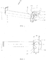
- FIG. 1 shows a mounting bracket 100 according to the invention in a perspective view from behind.
- the mounting bracket 100 has a Auslegearm 1, which is presently formed as a hollow profile with a round cross-section, a tube.
- the extension arm 1 extends the longitudinal axis L.
- a securing element 3 is formed from a folded sheet metal.
- the securing element 3 is fastened to the extension arm 1 with a welded connection.
- the holding device 2 consists in the present case of a stop element 23 which is fixed to a closing element 21, in the present case, these two elements are welded together.
- the closing element 21 is also fastened to the extension arm 1 with a welded connection.
- an engagement hook 22 At the top of the holding device 2 there is an engagement hook 22.
- the engagement hook 22 is welded to the closure element 21.
- an unspecified reinforcement element between the engagement hook 22 and the end element 21.
- On engaging hook 22 is also directed down a support element 24. Both the support member 24 and the unspecified reinforcing member are each welded to the engagement hook.
- the reinforcing element is additionally welded to the closing element 21.
- the closing element 21 has a guide contour F.
- the geometry of the guide contour F of the end element 21 is in the FIG. 4 explained in more detail.
- the stop element 23 is welded to the bottom of the end element 21 and has a round contour.
- the round contour of the stop element 23 substantially corresponds to the diameter of a tube of a vertical frame.
- the engagement hook 22 is made of a sheet metal.
- the engagement hook also has a contour that is related to FIG. 2 will be explained.
- the engagement hook has an engagement end 221.
- FIG. 2 shows a plan view of the mounting bracket 100 from the FIG. 1 in the final position.
- a final distance A1 between the engagement end 221 and the end element 21 is measured.
- a hook spacing A2 between the closing element 21 and an inner contour of the engagement hook 22 is also measured.
- the hook spacing A2 is in this case greater than the final distance A1.
- the hook spacing A2 is greater than the diameter of a tube of a vertical frame to which the mounting bracket is attached, and the end clearance A1 is smaller than said diameter.
- the inner contour of the engagement hook 22 is thus present partially formed according to the outer diameter or slightly larger than the outer diameter of the tube of the vertical frame.
- the inner contour of the engagement hook 22 has a substantially flat or straight region.
- the hook spacing A2 tapers to the distance of the end clearance A1.
- the stop element 23 is also recognizable. This extends on the side of the engagement end 221 of the engagement hook 22 about half as far as the final distance A1, wherein the length of the extension of the stop element 23 in the present case is slightly more than one third of the hook distance A2.
- the stopper member 23 is formed substantially symmetrically to a longitudinal axis of a pipe of the vertical frame (see FIG. 1 ).
- FIG. 3 shows a perspective view of the mounting bracket 100 from the front.
- the distance of the guide distance A3 between the engagement end 221 and the guide contour F is located.
- This guide distance A3 is presently greater than a diameter of a tube of a vertical frame.
- the guide distance A3 is thus greater than the end distance A1.
- the guide distance A3 is the shortest connection between the guide contour F and the engagement end 221.
- FIG. 4 shows a rear view of the mounting bracket 100.
- the closing element 21 is at least partially visible. Shown is centrally the longitudinal axis L, plotted is a distance A4.
- the distance A4 is substantially in a plane formed by the longitudinal axis L and the engagement end 221. As can be seen, the distance A4 is the shortest distance between the guide contour F of the closing element 21 and the longitudinal axis L. That is, a distance between the Guide contour F and the longitudinal axis L in the clockwise or counterclockwise direction starting from the drawn distance A4 in each case becomes larger.
- FIG. 5 shows a mounting bracket 100 on a vertical frame 200.
- the mounting bracket 100 rests with its support element 24 on a horizontal strut of the vertical frame 200 and is at the same time with its stop member 23 in engagement with a vertical strut of the vertical frame 200th
- Die Eingriffshaken 22 includes the vertical strut of the vertical frame 200.
- Both the vertical strut and the horizontal strut of the vertical frame 200 are presently formed with a round cross-section.
- a design which is essentially complementary to this cross-section is found on the engagement hook 22, on the stop element 23 and on the support element 24 (see FIG. 1 ).
- Other cross-sectional shapes of the horizontal strut as well as the vertical strut are conceivable.
- the cross sections of the horizontal strut and the vertical strut may also be different.
- the stop element 23, the support element 24 and the engagement hooks 22 are then formed accordingly.
Landscapes
- Engineering & Computer Science (AREA)
- Architecture (AREA)
- Mechanical Engineering (AREA)
- Civil Engineering (AREA)
- Structural Engineering (AREA)
- Emergency Lowering Means (AREA)
- Mutual Connection Of Rods And Tubes (AREA)
- Clamps And Clips (AREA)
Abstract
Description
- Die vorliegende Erfindung betrifft eine Befestigungskonsole für Gerüstbretter gemäss dem Oberbegriff der unabhängigen Ansprüche.
- Aus dem Stand der Technik sind unterschiedliche Befestigungskonsolen bekannt, die alternativ als Innenkonsole bekannt sind. Typischerweise sind derartige Befestigungskonsolen Zubehör für ein Gerüst, welches es ermöglichen soll, ein bestehendes Gerüst zu verbreitern, bzw. den Abstand zwischen einem Gerüst und beispielsweise einer Hauswand zu verringern. Damit soll einerseits die Sicherheit für die Arbeiter erhöht werden, andererseits soll der Zugang beispielsweise zum Gebäude erleichtert werden.
- Derartige Konsolen sind beispielsweise aus der
DE 2010359 U1 bekannt. Diese Konsole weist aber Nachteile auf, wie ungenügender Verdrehschutz oder Sicherung gegen Aushub. Im Stand der Technik wurden diese Nachteile erkannt und versucht, diese zu beheben. Dies führte zur Entwicklung einer Konsole gemäss derDE 10 2011 008 315 . Die aus derDE 10 2011 008 315 bekannte Befestigungskonsole weist an ihrem hinteren Ende ein U-Profil auf. Das U-Profil ist an seinem der Konsole abgewandten Ende mit einem Haken ausgerüstet, der in eingehängtem Zustand unter eine Quertraverse greifen soll. Damit soll ein unbeabsichtigtes Abheben der Konsole verhindert werden. - Die aus der
DE 10 2011 008 315 bekannte Konsole weist aber weiterhin beträchtliche Nachteile auf. So kann die Konsole beispielsweise am Gerüst eingehängt werden, ohne den Haken in Angriff zu bringen. Daher muss nach jedem Einhängen der Konsole kontrolliert werden, ob der Haken eingehängt ist, um die Sicherheit der Arbeiter zu gewährleisten. Ein horizontales Verdrehen der Konsole kann ebenfalls nicht verhindert werden. Dies führt dazu, dass der Monteur zusätzliche Schritte unternehmen muss, um einerseits das richtige Einhängen der Konsole zu kontrollieren und andererseits diese gegen Verdrehen zu sichern, beispielsweise mit einem Gerüstbrett. Dies macht das Arbeiten mit dieser Konsole unsicher und gefährlich. - Es daher Aufgabe der vorliegenden Erfindungen diese und/oder weitere Nachteile des Standes der Technik zu beheben. Insbesondere soll eine Befestigungskonsole bereitgestellt werden, die einfach zu fertigen, sicher in der Handhabe bei der Montage und sicher im Gebrauch ist.
- Diese Aufgabe wird durch die in den unabhängigen Patentansprüchen definierten Vorrichtungen gelöst. Weitere vorteilhafte Ausführungsformen ergeben sich aus den abhängigen Patentansprüchen.
- Eine erfindungsgemässe Befestigungskonsole für Gerüstbretter zur lösbaren Verbindung mit einem Rohr eines Vertikalrahmens umfasst einen Auslegearm zur Aufnahme eines Gerüstbrettes. Der Auslegearm weist eine Längsachse auf. Die Längsachse erstreckt sich im Wesentlichen zentral durch den Auslegearm. Die Befestigungskonsole weist eine Haltevorrichtung zur Befestigung der Befestigungskonsole an dem Rohr des Vertikalrahmens auf. Die Haltevorrichtung umfasst ein Abschlusselement und einen Eingriffshaken.
- In einer Endposition der Befestigungskonsole ist der Eingriffshaken oben an der Haltevorrichtung angeordnet. Dabei befindet sich die Haltevorrichtung definitionsgemäss am hinteren Ende der Befestigungskonsole. Die Längsachse erstreckt sich somit definitionsgemäss ebenfalls vom hinteren Ende in Richtung vorderes Ende der Befestigungskonsole. Der Eingriffshaken ist derart ausgebildet, dass er das Rohr des Vertikalrahmens in der Endposition in Richtung der Längsachse um mehr als 180° umfasst. Der Eingriffshaken weist an seinem Ende ein Eingriffsende auf. Das heisst, beginnend mit der Orientierung der Längsachse erstreckt sich der Eingriffshaken zumindest bis in die entgegengesetzte Richtung der Längsachse nämlich um mindestens 180°.
- Das Eingriffsende des Eingriffshakens weist in Richtung der Längsachse einen Endabstand zu dem Abschlusselement auf, der kleiner ist als ein Hakenabstand des Eingriffshakens zu dem Abschlusselement entlang der Längsachse. Dabei ist der Hakenabstand als der Abstand definiert, der zwischen einer Innenkontur des Hakens und dem Abschlusselement in einer Draufsicht auf die Befestigungskonsole in der Endposition entlang der Längsachse gemessen wird. Eine Innenkontur des Eingriffshakens kann dabei sowohl gerade als auch gebogen ausgebildet sein.
- Das Abschlusselement weist eine Führungskontur auf, die derart ausgebildet ist, dass ein Führungsabstand zwischen der Führungskontur und dem Eingriffsende zumindest gleich gross oder grösser ist als der Hakenabstand des Eingriffshakens zu dem Abschlusselement entlang der Längsachse. So, dass die Befestigungskonsole erst in einer zur Endposition gekippten und verdrehten Lage am Vertikalrahmen einhängbar ist. Vorzugsweise weist die Befestigungskonsole zur Verdrehsicherung ein zum Eingriffshaken beabstandetes Anschlagelement auf.
- In der vorliegenden Beschreibung wird verschiedentlich Bezug genommen auf unterschiedliche Lagen oder Positionsbezeichnungen wie oben, unten, hinten und vorne. Definitionsgemäss handelt es sich hierbei um Lagebezeichnungen in der erfindungsgemässen Endlage der Befestigungskonsole im eingebauten Zustand. Dabei bedeutet hinten der Bereich oder die Richtung zum Vertikalrahmen hin und vorne die entgegengesetzte Richtung, d.h. vom Vertikalrahmen weg.
- Die spezifische, wie vorliegend dargestellte Anordnung der unterschiedlichen Abstände, insbesondere die Relation von Endabstand zu Hakenabstand erzwingt beim Befestigen der Befestigungskonsole am Rohr des Vertikalrahmens eine spezifische Position. Diese Position ist zur Endposition der Befestigungskonsole gekippt und verdreht. Das heisst, die Befestigungskonsole befindet sich beim Einbauen in einer Position die mindestens zwei überlagerte Bewegungen voraussetzt. Nach dem Einhängen und dem Zurückkippen und Zurückdrehen der Befestigungskonsole in die Endposition ist ein versehentliches Ausheben oder Abstreifen der Befestigungskonsole vom Vertikalrahmen verhindert. Eine für eine Fehlmanipulation typische Bewegung in einer Achse genügt nicht, um die Befestigungskonsole vom Rohr des Vertikalrahmens zu trennen. Ebenfalls genügt ein Verdrehen der Befestigungskonsole alleine nicht, um diese vom Vertikalrahmen zu trennen. Eine kombinierte translatorische und rotatorische Bewegung der Befestigungskonsole ist sehr unwahrscheinlich. Damit ist das Befestigen der Befestigungskonsole für einen Arbeiter unproblematisch, ein versehentliches Lösen durch äussere Einflüsse jedoch verhindert.
- Vorzugsweise ist die die Kontur des Anschlagelementes derart ausgebildet, dass sie das Rohr um mehr als einen Viertel umfasst. Damit ist eine genügend grosse Anschlagfläche bereitgestellt.
- In einer bevorzugten Ausführungsform weist das Anschlagelement eine Kontur auf, die derart ausgebildet ist, dass sie sich in einer Endposition der Befestigungskonsole in Richtung zum Vertikalrohr hin über eine Distanz von mehr als einem Viertel des Durchmessers des Vertikalrohres erstreckt, vorzugsweise über mehr als die Hälfte des Durchmessers des Rohres.
- Dies ermöglicht eine zusätzliche Stabilisierung der Befestigungskonsole.
- Vorzugsweise erstreckt sich das Anschlagelement in Bezug auf die Längsachse des Auslegearms auf der gleichen Seite wie das Eingriffsende des Eingriffshakens.
- Dies ermöglicht eine zusätzliche Sicherung in Bezug auf Verdrehen der Befestigungskonsole.
- Vorzugsweise erstreckt sich die Kontur des Anschlagelementes zumindest einseitig über mindestens einen Drittel des Endabstandes zwischen dem Eingriffshaken und dem Abschlusselement.
- Ein Verdrehen oder seitliches Verrutschen der Befestigungskonsole ist damit zusätzlich verhindert.
- In einer bevorzugten Ausführungsform ist die Kontur des Anschlagelementes derart ausgebildet, dass sie im Wesentlichen komplementär zum Rohr des Vertikalrahmens ist. Vorzugsweise entspricht die Kontur des Anschlagelementes im Wesentlichen dem Aussendurchmesser des Rohres des Vertikalrahmens oder ist etwas grösser ausgebildet, beispielsweise können sich die Durchmesser im Bereich von 1mm bis 5mm unterscheiden.
- Es wäre aber ebenfalls vorstellbar, dass die Kontur derart ausgebildet ist, dass sie im Wesentlichen nur drei Berührungspunkte mit dem Rohr aufweist, so könnte beispielsweise je eine Lasche beidseitig des Rohres und eine mittlere Anschlagfläche das Anschlagelement bilden.
- Die Befestigungskonsole kann beim Eingriffselement und vorzugsweise am Eingriffshaken ein Auflageelement zur Auflage auf ein Querrohr des Vertikalrahmens aufweisen.
- Dies ermöglicht eine gleichmässige vertikale Positionierung der Befestigungskonsole.
- Das Auflageelement kann ebenfalls vorzugsweise im Wesentlichen komplementär zum Querrohr des Vertikalrahmens ausgebildet sein. Dabei kann sich die Kontur des Auflageelementes vorzugsweise über mehr als einen Viertel eines Durchmessers des Querrohres erstrecken, so, dass beispielsweise sich die Kontur beidseitig des Querrohres erstreckt.
- Dies verhindert ein unbeabsichtigtes Verdrehen der Befestigungskonsole um eine Längsachse des Rohres des Vertikalrahmens.
- Am Auslegearm der Befestigungskonsole kann ein Sicherungselement zum Rückhalten eines auf der Befestigungskonsole angebrachten oder aufzubringendem Gerüstbrettes angeordnet sein.
- Damit ist es möglich, dass zur Sicherung des Gerüstbrettes keine zusätzlichen Massnahmen notwendig sind. Andererseits ist durch Einlegen des Gerüstbrettes die Position der Befestigungskonsole zusätzlich gesichert.
- Der Auslegearm der Befestigungskonsole kann als Hohlprofil und insbesondere als rundes Rohr ausgebildet sein. Andere Querschnitte von Hohlprofilen aber ebenso konventionelle T- oder H-Profile sowie U-Profile wären ebenfalls vorstellbar. Die Ausbildung als Rohr ermöglicht eine einfache Fertigung und stellt eine erhöhte Stabilität bereit.
- Vorzugsweise entspricht der Endabstand des Eingriffshakens zu dem Abschlusselement maximal dem 0,9-fachen des Hakenabstandes des Eingriffshakens zu dem Abschlusselement entlang oder in der Richtung der Längsachse.
- Damit sind Mindestanforderungen bereitgestellt, die eine gewünschte Sicherheit gegen das Ausheben der Befestigungskonsole aus der Endposition gewährleisten.
- Vorzugsweise weist die Führungskontur senkrecht zur Längsachse in einer durch die Längsachse und dem Eingriffsende gebildeten Ebene einen, gegenüber Abständen in zu dieser Ebene verdrehten Ebenen, kürzesten Abstand auf. Damit ist eine gewünschte Verdrehposition während des Einbauens eindeutig definiert.
- In einer bevorzugten Ausführungsform ist die Führungskontur zumindest aus einem ersten und einem zweiten sowie einem gekrümmten Abschnitt gebildet. Dabei kann beispielsweise der erste und der zweite Abschnitt eine gerade Kontur aufweisen und der gekrümmte Abschnitt einen im Wesentlichen konstanten Radius zu der Längsachse.
- Dies ermöglicht ebenfalls ein einfaches Befestigen der Befestigungskonsole am Rohr des Vertikalrahmens, da die Kontur so einen exakten Bewegungsablauf vorgibt.
- Sowohl das Abschlusselement, der Eingriffshaken, das Anschlagelement als auch das Auflageelement können je aus einem Blech gefertigt sein. Zur Stabilisierung können ebenso Stabilisierungselemente aus Blechen vorgesehen sein. Das Sicherungselement kann ebenso aus einem Blech gefertigt sein.
- Dies ermöglicht eine einfache und genaue Fertigung. Beispielsweise können alle Bleche als Laserschnittteile gefertigt werden. Vorzugsweise weisen die Bleche an ihren Schnittstellen Eingriffselemente zur Positionierung und/oder zur einfachen Fertigung auf. Alternativ ist es ebenso vorstellbar, zwei oder mehrere Elemente gemeinsam als Biegeteil zu fertigen, beispielsweise das Anschlagelement gemeinsam mit dem Abschlusselement oder das Abschlusselement gemeinsam mit dem Eingriffshaken. Ebenso könnte der Eingriffshaken gemeinsam mit dem Auflageelement aus einem einzigen Teil gebogen werden. Alternativ wäre es ebenso vorstellbar, drei oder mehr Elemente aus einem einzelnen Blechbiegeteil zu fertigen.
- Vorzugsweise sind die einzelnen Elemente jedoch miteinander und mit dem Auslegearm verschweisst.
- Je nach gewünschtem Vorteil, beispielsweise Genauigkeit oder Kosten ist eine der Varianten zu bevorzugen.
- Eine erfindungsgemässe Ausführungsform wird an Hand der folgenden Figuren erklärt. Es zeigen:
- Figur 1:
- Eine perspektivische Ansicht einer erfindungsgemässen Befestigungskonsole von schräg hinten;
- Figur 2:
- die Befestigungskonsole gemäss
Figur 1 in einer Draufsicht auf die Endposition; - Figur 3:
- eine erfindungsgemässe Befestigungskonsole in einer perspektivischen Ansicht von schräg vorne.
- Figur 4:
- Eine Ansicht von hinten auf die Befestigungskonsole gemäss der
Figur 1 - Figur 5:
- Eine Befestigungskonsole an einem Vertikalrahmen
-
Figur 1 zeigt eine erfindungsgemässe Befestigungskonsole 100 in einer perspektivischen Ansicht von hinten. Die Befestigungskonsole 100 weist einen Auslegearm 1 auf, der vorliegend als Hohlprofil mit einem runden Querschnitt, einem Rohr, gebildet ist. Durch den Auslegearm 1 erstreckt sich die Längsachse L. Gemäss der allgemeinen Definition vorne an der Befestigungskonsole 100 befindet sich am Auslegearm 1 ein Sicherungselement 3. Das Sicherungselement 3 ist aus einem abgekanteten Blech gebildet. Das Sicherungselement 3 ist mit einer Schweissverbindung am Auslegearm 1 befestigt. Gemäss der vorliegenden Definition am hinteren Ende der Befestigungskonsole 100 befindet sich die Haltevorrichtung 2. Die Haltevorrichtung 2 besteht vorliegend aus einem Anschlagelement 23, welches an einem Abschlusselement 21 befestigt ist, vorliegend sind diese beiden Elemente miteinander verschweisst. Das Abschlusselement 21 ist ebenso mit einer Schweissverbindung am Auslegearm 1 befestigt. Oben an der Haltevorrichtung 2 befindet sich ein Eingriffshaken 22. Der Eingriffshaken 22 ist mit dem Abschlusselement 21 verschweisst. Zur Stabilisierung befindet sich zwischen dem Eingriffshaken 22 und dem Abschlusselement 21 ein nicht näher bezeichnetes Verstärkungselement. Am Eingriffshaken 22 befindet sich zudem nach unten gerichtet ein Auflageelement 24. Sowohl das Auflageelement 24 als auch das nicht näher bezeichnete Verstärkungselement sind jeweils mit dem Eingriffshaken verschweisst. Das Verstärkungselement ist zusätzlich mit dem Abschlusselement 21 verschweisst. - Das Abschlusselement 21 weist eine Führungskontur F auf. Die Geometrie der Führungskontur F des Abschlusselements 21 wird in der
Figur 4 näher erläutert. Das Anschlagelement 23 ist unten am Abschlusselement 21 angeschweisst und weist eine runde Kontur auf. Die runde Kontur des Anschlagelementes 23 entspricht im Wesentlichen dem Durchmesser eines Rohres eines Vertikalrahmens. - Wie vorstehend erläutert, ist der Eingriffshaken 22 aus einem Blech gefertigt. Der Eingriffshaken weist ebenso eine Kontur auf, die in Bezug zu
Figur 2 noch erläutert wird. Der Eingriffshaken weist ein Eingriffsende 221 auf. -
Figur 2 zeigt eine Draufsicht auf die Befestigungskonsole 100 aus derFigur 1 in der Endposition. In Richtung der Längsachse L wird ein Endabstand A1 zwischen dem Eingriffsende 221 und dem Abschlusselement 21 gemessen. Im Bereich der Längsachse L wird zudem ein Hakenabstand A2 zwischen dem Abschlusselement 21 und einer Innenkontur des Eingriffshakens 22 gemessen. Der Hakenabstand A2 ist dabei vorliegend grösser als der Endabstand A1. Insbesondere ist der Hakenabstand A2 grösser als der Durchmesser eines Rohres eines Vertikalrahmens an den die Befestigungskonsole befestigt wird und der Endabstand A1 ist kleiner als der genannte Durchmesser. Damit ist ein Verschieben der Befestigungskonsole 100 entlang der Zeichnungsebene in der Endposition der Befestigungskonsole 100 nicht mehr möglich. Die Innenkontur des Eingriffshakens 22 ist vorliegend somit teilweise entsprechend dem Aussendurchmesser oder geringfügig grösser als der Aussendurchmesser des Rohres des Vertikalrahmens ausgebildet. Im Bereich der Längsachse L weist die Innenkontur des Eingriffshakens 22 einen im Wesentlichen flachen oder geraden Bereich auf. In Richtung des Eingriffsendes 221 verjüngt sich der Hakenabstand A2 bis auf die Distanz des Endabstandes A1. In dieser Draufsicht ist ebenso das Anschlagelement 23 erkennbar. Dieses erstreckt sich auf der Seite des Eingriffsendes 221 des Eingriffshakens 22 ungefähr halb so weit wie der Endabstand A1, wobei die Länge der Erstreckung des Anschlagelementes 23 vorliegend etwas mehr als einen Drittel des Hakenabstandes A2 ist. Das Anschlagelement 23 ist zu einer Längsachse eines Rohres des Vertikalrahmens im Wesentlichen symmetrisch ausgebildet (sieheFigur 1 ). -
Figur 3 zeigt eine perspektivische Ansicht der Befestigungskonsole 100 von vorne. Dabei ist der Abstand der Führungsabstand A3 zwischen dem Eingriffsende 221 und der Führungskontur F eingezeichnet. Dieser Führungsabstand A3 ist vorliegend grösser als ein Durchmesser eines Rohres eines Vertikalrahmens. Der Führungsabstand A3 ist damit grösser als der Endabstand A1. Der Führungsabstand A3 ist die kürzeste Verbindung zwischen der Führungskontur F und dem Eingriffsende 221. -
Figur 4 zeigt eine Hinteransicht der Befestigungskonsole 100. Das Abschlusselement 21 ist zumindest teilweise sichtbar. Gezeigt ist zentral die Längsachse L, eingezeichnet ist ein Abstand A4. Der Abstand A4 liegt im Wesentlichen in einer Ebene gebildet durch die Längsachse L und das Eingriffsende 221. Wie ersichtlich ist, ist der Abstand A4 der kürzeste Abstand zwischen der Führungskontur F des Abschlusselementes 21 und der Längsachse L. Das heisst, dass ein Abstand zwischen der Führungskontur F und der Längsachse L im Uhrzeigersinn oder gegen den Uhrzeigersinn ausgehend vom eingezeichneten Abstand A4 jeweils grösser wird. -
Figur 5 zeigt eine Befestigungskonsole 100 an einem Vertikalrahmen 200. Die Befestigungskonsole 100 liegt mit ihrem Auflageelement 24 auf einer Horizontalstrebe des Vertikalrahmens 200 auf und ist zugleich mit ihrem Anschlagelement 23 in Eingriff mit einer Vertikalstrebe des Vertikalrahmens 200. Der Eingriffshaken 22 umfasst dabei die Vertikalstrebe des Vertikalrahmens 200. Sowohl die Vertikalstrebe als auch die Horizontalstrebe des Vertikalrahmens 200 sind vorliegend mit einem runden Querschnitt ausgebildet. Eine zu diesem Querschnitt im Wesentlichen komplementäre Ausbildung findet sich am Eingriffshaken 22, am Anschlagelement 23 und am Auflageelement 24 (siehe dazuFigur 1 ). Andere Querschnittsformen der Horizontalstrebe wie auch der Vertikalstrebe sind vorstellbar. Die Querschnitte der Horizontalstrebe und der Vertikalstrebe können auch unterschiedlich sein. Das Anschlagelement 23, das Auflageelement 24 und der Eingriffshaken 22 sind dann entsprechend ausgebildet.
Claims (10)
- Befestigungskonsole (100) für Gerüstbretter zur lösbaren Verbindung an einem Rohr eines Vertikalrahmens, umfassend einen Auslegearm (1) mit einer Längsachse (L) zur Aufnahme eines Gerüstbrettes und eine Haltevorrichtung (2) zur Befestigung der Befestigungskonsole an dem Rohr, wobei die Haltevorrichtung (2) ein Abschlusselement (21) und einen Eingriffshaken (22) umfasst, dadurch gekennzeichnet, dass der Eingriffshaken (22) in einer Endposition der Befestigungskonsole (100) an der Haltevorrichtung (2) oben angeordnet ist, wobei der Eingriffshaken (22) derart ausgebildet ist, dass er in Richtung der Längsachse (L) das Rohr um mehr als 180° umfasst und an seinem Ende ein Eingriffsende (221) aufweist, wobei das Eingriffsende (221) des Eingriffshakens (22) in Richtung der Längsachse (L) einen Endabstand (A1) zu dem Abschlusselement (21) aufweist, der kleiner ist als ein Hakenabstand (A2) des Eingriffshakens (22) zu dem Abschlusselement (21) entlang der Längsachse (L), wobei das Abschlusselement (21) eine Führungskontur (F) aufweist die derart ausgebildet ist, dass ein Führungsabstand (A3) zwischen der Führungskontur (F) und dem Eingriffsende (221) zumindest gleich gross oder grösser ist als der Hakenabstand (A2) des Eingriffshakens (22) zu dem Abschlusselement (21) entlang der Längsachse (L), so dass die Befestigungskonsole (100) erst in einer zur Endposition gekippten und verdrehten Lage am Vertikalrahmen einhängbar ist, wobei vorzugsweise zur Verdrehsicherung ein zum Eingriffshaken (22) beabstandetes Anschlagelement (23) vorgesehen ist.
- Befestigungskonsole (100) nach Anspruch 1, dadurch gekennzeichnet, dass das Anschlagelement (23) eine Kontur aufweist, die derart ausgebildet ist, dass sie in einer Endposition der Befestigungskonsole (10) das Rohr um mehr als einen Viertel umfasst.
- Befestigungskonsole (100) nach Anspruch 2, dadurch gekennzeichnet, dass die Kontur des Anschlagelementes (23) sich zumindest einseitig über mindestens einen Drittel des Endabstandes A1 zwischen dem Eingriffshaken (22) und dem Abschlusselement (21) erstreckt.
- Befestigungskonsole (100) nach Anspruch 2 oder 3, dadurch gekennzeichnet, dass die Kontur des Anschlagelementes (23) derart ausgebildet ist, das sie im Wesentlichen komplementär zum Rohr des Vertikalrahmens ist.
- Befestigungskonsole (100) nach einem der Ansprüche 1 bis 4, dadurch gekennzeichnet, dass am Eingriffselement (2) und vorzugsweise am Eingriffshaken (22) ein Auflageelement (24) zur Auflage auf einem Querrohr des Vertikalrahmens vorgesehen ist.
- Befestigungskonsole (100) nach einem der Ansprüche 1 bis 5, dadurch gekennzeichnet, dass am Auslegearm (1) ein Sicherungselement (3) zum Rückhalten des Gerüstbrettes angeordnet ist.
- Befestigungskonsole (100) nach einem der Ansprüche 1 bis 6, dadurch gekennzeichnet, dass der Auslegearm (1) als Rohr ausgebildet ist.
- Befestigungskonsole (100) nach einem der Ansprüche 1 bis 7, dadurch gekennzeichnet, dass der Endabstand (A1) des Eingriffshakens (22) zu dem Abschlusselement (21) maximal dem 0.9fachen des Hakenabstandes (A2) des Eingriffshakens (22) zu dem Abschlusselement (21) entlang der Längsachse entspricht.
- Befestigungskonsole (100) nach einem der Ansprüche 1 bis 8, dadurch gekennzeichnet, dass die Führungskontur (F) senkrecht zur Längsachse in einer durch die Längsachse (L) und den Eingriffsende (221) gebildeten Ebene einen, gegenüber Abständen in zu dieser Ebene verdrehten Ebenen, kürzesten Abstand (A4) aufweist.
- Befestigungskonsole (100) nach einem der Ansprüche 1 bis 9, dadurch gekennzeichnet, dass die Führungskontur (F) zumindest aus einem ersten und einem zweiten sowie einem gekrümmten Abschnitt gebildet ist.
Priority Applications (2)
| Application Number | Priority Date | Filing Date | Title |
|---|---|---|---|
| RS20200409A RS60145B1 (sr) | 2016-12-21 | 2016-12-21 | Konzola za pričvršćivanje skelnih platformi |
| EP16205601.4A EP3339534B1 (de) | 2016-12-21 | 2016-12-21 | Befestigungskonsole für gerüstbretter |
Applications Claiming Priority (1)
| Application Number | Priority Date | Filing Date | Title |
|---|---|---|---|
| EP16205601.4A EP3339534B1 (de) | 2016-12-21 | 2016-12-21 | Befestigungskonsole für gerüstbretter |
Publications (2)
| Publication Number | Publication Date |
|---|---|
| EP3339534A1 true EP3339534A1 (de) | 2018-06-27 |
| EP3339534B1 EP3339534B1 (de) | 2020-02-26 |
Family
ID=57590361
Family Applications (1)
| Application Number | Title | Priority Date | Filing Date |
|---|---|---|---|
| EP16205601.4A Active EP3339534B1 (de) | 2016-12-21 | 2016-12-21 | Befestigungskonsole für gerüstbretter |
Country Status (2)
| Country | Link |
|---|---|
| EP (1) | EP3339534B1 (de) |
| RS (1) | RS60145B1 (de) |
Cited By (2)
| Publication number | Priority date | Publication date | Assignee | Title |
|---|---|---|---|---|
| WO2023233198A1 (es) * | 2022-05-31 | 2023-12-07 | Sistemas Técnicos de Encofrados S.A. | Cartela de soporte de perfiles y sistema de recuperación de tableros |
| EP4303378A1 (de) | 2022-07-08 | 2024-01-10 | MJ-Gerüst GmbH | Gerüstkonsole für ein modulgerüst sowie modulgerüst mit zumindest einer solchen gerüstkonsole |
Citations (6)
| Publication number | Priority date | Publication date | Assignee | Title |
|---|---|---|---|---|
| JPS5112429U (de) * | 1974-07-16 | 1976-01-29 | ||
| JPS5276628U (de) * | 1975-12-05 | 1977-06-08 | ||
| JPS5570853U (de) * | 1978-11-10 | 1980-05-15 | ||
| JPS61120851U (de) * | 1985-01-16 | 1986-07-30 | ||
| DE20103596U1 (de) | 2001-03-01 | 2001-05-10 | Günter Rux GmbH, 58135 Hagen | Konsole für Baugerüste |
| DE102011008315A1 (de) | 2011-01-11 | 2012-07-12 | Rux Gmbh | Konsole für Baugerüste |
-
2016
- 2016-12-21 RS RS20200409A patent/RS60145B1/sr unknown
- 2016-12-21 EP EP16205601.4A patent/EP3339534B1/de active Active
Patent Citations (6)
| Publication number | Priority date | Publication date | Assignee | Title |
|---|---|---|---|---|
| JPS5112429U (de) * | 1974-07-16 | 1976-01-29 | ||
| JPS5276628U (de) * | 1975-12-05 | 1977-06-08 | ||
| JPS5570853U (de) * | 1978-11-10 | 1980-05-15 | ||
| JPS61120851U (de) * | 1985-01-16 | 1986-07-30 | ||
| DE20103596U1 (de) | 2001-03-01 | 2001-05-10 | Günter Rux GmbH, 58135 Hagen | Konsole für Baugerüste |
| DE102011008315A1 (de) | 2011-01-11 | 2012-07-12 | Rux Gmbh | Konsole für Baugerüste |
Cited By (3)
| Publication number | Priority date | Publication date | Assignee | Title |
|---|---|---|---|---|
| WO2023233198A1 (es) * | 2022-05-31 | 2023-12-07 | Sistemas Técnicos de Encofrados S.A. | Cartela de soporte de perfiles y sistema de recuperación de tableros |
| EP4303378A1 (de) | 2022-07-08 | 2024-01-10 | MJ-Gerüst GmbH | Gerüstkonsole für ein modulgerüst sowie modulgerüst mit zumindest einer solchen gerüstkonsole |
| DE102022002503A1 (de) | 2022-07-08 | 2024-01-11 | MJ-Gerüst GmbH | Gerüstkonsole für ein Modulgerüst sowie Modulgerüst mit zumindest einer solchen Gerüstkonsole |
Also Published As
| Publication number | Publication date |
|---|---|
| EP3339534B1 (de) | 2020-02-26 |
| RS60145B1 (sr) | 2020-05-29 |
Similar Documents
| Publication | Publication Date | Title |
|---|---|---|
| EP2132388B1 (de) | Belageinheit mit abhebesicherung und verfahren zur sicherung einer belageinheit gegen abheben sowie verfahren zur entsicherung einer gegen abheben gesicherten belageinheit | |
| DE2637142C3 (de) | Leiter zum Einbau an und parallel zu einer Wandung o.dgl | |
| EP3339534B1 (de) | Befestigungskonsole für gerüstbretter | |
| EP3596297B1 (de) | Grabenverbau mit einem leitersystem | |
| EP3712354B1 (de) | Schalungsbühne | |
| DE102011008315B4 (de) | Konsole für Baugerüste | |
| EP3339533B1 (de) | Befestigungskonsole für gerüstbretter | |
| DE102021101679A1 (de) | Vorrichtung zur Anbringung einer Deckenschalplatte, Deckenschalung, Deckenpaneel für eine Deckenschalung, Trägerleiste, Trägereinheit, Trägeranschluss und Trägerhalter | |
| EP2532982B1 (de) | Vorrichtung zur Sicherung eines mittels Aufhängelaschen in einer mit Aufnahmeschlitz versehenen Konsole gehaltenen Heizkörpers | |
| DE19527944C2 (de) | Gerüsthalter für Bockleitern oder dergleichen | |
| EP1155638B1 (de) | Lösbare Verbindung eines Auslegers mit einer Stütze | |
| EP3892789B1 (de) | Schalungssystem | |
| EP1247717B1 (de) | Halterungseinrichtung für ein Signal, insbesondere für ein Eisenbahnsignal | |
| DE202020103951U1 (de) | Sicherungsgeländer | |
| WO2002066767A1 (de) | Verbindungskonstruktion für bauteile eines systemgerüsts, kupplungseinheit und gerüstrahmen hierfür | |
| DE102014222247A1 (de) | Seitengeländer für einen Gerüstturm | |
| EP3611313A1 (de) | Vorrichtung zum befestigen von lasten an der unterseite eines gerüstbodens eines gerüstes | |
| DE8104076U1 (de) | Auslegerbefestigungsvorrichtung | |
| DE20221676U1 (de) | Verbindungskonstruktion für Gerüstrahmen | |
| AT519309B1 (de) | Befestigungswinkel für deckenrandabschalungen | |
| EP3444414B1 (de) | Gerüst mit konsole | |
| DE202009008593U1 (de) | Halterung für Heizkörper | |
| EP3168389A1 (de) | Absturzsicherungseinrichtung | |
| EP2719847A2 (de) | Konsole für ein Fassadengerüst mit einer verschiebbar gelagerten Teilkonsole | |
| DE10046223A1 (de) | Halterung für einen mit Laschen versehenen Heizkörper |
Legal Events
| Date | Code | Title | Description |
|---|---|---|---|
| PUAI | Public reference made under article 153(3) epc to a published international application that has entered the european phase |
Free format text: ORIGINAL CODE: 0009012 |
|
| STAA | Information on the status of an ep patent application or granted ep patent |
Free format text: STATUS: THE APPLICATION HAS BEEN PUBLISHED |
|
| AK | Designated contracting states |
Kind code of ref document: A1 Designated state(s): AL AT BE BG CH CY CZ DE DK EE ES FI FR GB GR HR HU IE IS IT LI LT LU LV MC MK MT NL NO PL PT RO RS SE SI SK SM TR |
|
| AX | Request for extension of the european patent |
Extension state: BA ME |
|
| STAA | Information on the status of an ep patent application or granted ep patent |
Free format text: STATUS: REQUEST FOR EXAMINATION WAS MADE |
|
| 17P | Request for examination filed |
Effective date: 20181108 |
|
| RBV | Designated contracting states (corrected) |
Designated state(s): AL AT BE BG CH CY CZ DE DK EE ES FI FR GB GR HR HU IE IS IT LI LT LU LV MC MK MT NL NO PL PT RO RS SE SI SK SM TR |
|
| STAA | Information on the status of an ep patent application or granted ep patent |
Free format text: STATUS: EXAMINATION IS IN PROGRESS |
|
| 17Q | First examination report despatched |
Effective date: 20190228 |
|
| GRAP | Despatch of communication of intention to grant a patent |
Free format text: ORIGINAL CODE: EPIDOSNIGR1 |
|
| STAA | Information on the status of an ep patent application or granted ep patent |
Free format text: STATUS: GRANT OF PATENT IS INTENDED |
|
| INTG | Intention to grant announced |
Effective date: 20191010 |
|
| GRAS | Grant fee paid |
Free format text: ORIGINAL CODE: EPIDOSNIGR3 |
|
| GRAA | (expected) grant |
Free format text: ORIGINAL CODE: 0009210 |
|
| STAA | Information on the status of an ep patent application or granted ep patent |
Free format text: STATUS: THE PATENT HAS BEEN GRANTED |
|
| AK | Designated contracting states |
Kind code of ref document: B1 Designated state(s): AL AT BE BG CH CY CZ DE DK EE ES FI FR GB GR HR HU IE IS IT LI LT LU LV MC MK MT NL NO PL PT RO RS SE SI SK SM TR |
|
| REG | Reference to a national code |
Ref country code: GB Ref legal event code: FG4D Free format text: NOT ENGLISH |
|
| REG | Reference to a national code |
Ref country code: CH Ref legal event code: EP |
|
| REG | Reference to a national code |
Ref country code: AT Ref legal event code: REF Ref document number: 1237787 Country of ref document: AT Kind code of ref document: T Effective date: 20200315 |
|
| REG | Reference to a national code |
Ref country code: IE Ref legal event code: FG4D Free format text: LANGUAGE OF EP DOCUMENT: GERMAN |
|
| REG | Reference to a national code |
Ref country code: DE Ref legal event code: R096 Ref document number: 502016008908 Country of ref document: DE |
|
| PG25 | Lapsed in a contracting state [announced via postgrant information from national office to epo] |
Ref country code: FI Free format text: LAPSE BECAUSE OF FAILURE TO SUBMIT A TRANSLATION OF THE DESCRIPTION OR TO PAY THE FEE WITHIN THE PRESCRIBED TIME-LIMIT Effective date: 20200226 Ref country code: NO Free format text: LAPSE BECAUSE OF FAILURE TO SUBMIT A TRANSLATION OF THE DESCRIPTION OR TO PAY THE FEE WITHIN THE PRESCRIBED TIME-LIMIT Effective date: 20200526 |
|
| REG | Reference to a national code |
Ref country code: NL Ref legal event code: MP Effective date: 20200226 |
|
| REG | Reference to a national code |
Ref country code: LT Ref legal event code: MG4D |
|
| PG25 | Lapsed in a contracting state [announced via postgrant information from national office to epo] |
Ref country code: LV Free format text: LAPSE BECAUSE OF FAILURE TO SUBMIT A TRANSLATION OF THE DESCRIPTION OR TO PAY THE FEE WITHIN THE PRESCRIBED TIME-LIMIT Effective date: 20200226 Ref country code: GR Free format text: LAPSE BECAUSE OF FAILURE TO SUBMIT A TRANSLATION OF THE DESCRIPTION OR TO PAY THE FEE WITHIN THE PRESCRIBED TIME-LIMIT Effective date: 20200527 Ref country code: HR Free format text: LAPSE BECAUSE OF FAILURE TO SUBMIT A TRANSLATION OF THE DESCRIPTION OR TO PAY THE FEE WITHIN THE PRESCRIBED TIME-LIMIT Effective date: 20200226 Ref country code: SE Free format text: LAPSE BECAUSE OF FAILURE TO SUBMIT A TRANSLATION OF THE DESCRIPTION OR TO PAY THE FEE WITHIN THE PRESCRIBED TIME-LIMIT Effective date: 20200226 Ref country code: IS Free format text: LAPSE BECAUSE OF FAILURE TO SUBMIT A TRANSLATION OF THE DESCRIPTION OR TO PAY THE FEE WITHIN THE PRESCRIBED TIME-LIMIT Effective date: 20200626 |
|
| PG25 | Lapsed in a contracting state [announced via postgrant information from national office to epo] |
Ref country code: NL Free format text: LAPSE BECAUSE OF FAILURE TO SUBMIT A TRANSLATION OF THE DESCRIPTION OR TO PAY THE FEE WITHIN THE PRESCRIBED TIME-LIMIT Effective date: 20200226 |
|
| PG25 | Lapsed in a contracting state [announced via postgrant information from national office to epo] |
Ref country code: PT Free format text: LAPSE BECAUSE OF FAILURE TO SUBMIT A TRANSLATION OF THE DESCRIPTION OR TO PAY THE FEE WITHIN THE PRESCRIBED TIME-LIMIT Effective date: 20200719 Ref country code: LT Free format text: LAPSE BECAUSE OF FAILURE TO SUBMIT A TRANSLATION OF THE DESCRIPTION OR TO PAY THE FEE WITHIN THE PRESCRIBED TIME-LIMIT Effective date: 20200226 Ref country code: SK Free format text: LAPSE BECAUSE OF FAILURE TO SUBMIT A TRANSLATION OF THE DESCRIPTION OR TO PAY THE FEE WITHIN THE PRESCRIBED TIME-LIMIT Effective date: 20200226 Ref country code: RO Free format text: LAPSE BECAUSE OF FAILURE TO SUBMIT A TRANSLATION OF THE DESCRIPTION OR TO PAY THE FEE WITHIN THE PRESCRIBED TIME-LIMIT Effective date: 20200226 Ref country code: CZ Free format text: LAPSE BECAUSE OF FAILURE TO SUBMIT A TRANSLATION OF THE DESCRIPTION OR TO PAY THE FEE WITHIN THE PRESCRIBED TIME-LIMIT Effective date: 20200226 Ref country code: DK Free format text: LAPSE BECAUSE OF FAILURE TO SUBMIT A TRANSLATION OF THE DESCRIPTION OR TO PAY THE FEE WITHIN THE PRESCRIBED TIME-LIMIT Effective date: 20200226 Ref country code: SM Free format text: LAPSE BECAUSE OF FAILURE TO SUBMIT A TRANSLATION OF THE DESCRIPTION OR TO PAY THE FEE WITHIN THE PRESCRIBED TIME-LIMIT Effective date: 20200226 Ref country code: EE Free format text: LAPSE BECAUSE OF FAILURE TO SUBMIT A TRANSLATION OF THE DESCRIPTION OR TO PAY THE FEE WITHIN THE PRESCRIBED TIME-LIMIT Effective date: 20200226 Ref country code: ES Free format text: LAPSE BECAUSE OF FAILURE TO SUBMIT A TRANSLATION OF THE DESCRIPTION OR TO PAY THE FEE WITHIN THE PRESCRIBED TIME-LIMIT Effective date: 20200226 |
|
| REG | Reference to a national code |
Ref country code: DE Ref legal event code: R097 Ref document number: 502016008908 Country of ref document: DE |
|
| PLBE | No opposition filed within time limit |
Free format text: ORIGINAL CODE: 0009261 |
|
| STAA | Information on the status of an ep patent application or granted ep patent |
Free format text: STATUS: NO OPPOSITION FILED WITHIN TIME LIMIT |
|
| PG25 | Lapsed in a contracting state [announced via postgrant information from national office to epo] |
Ref country code: IT Free format text: LAPSE BECAUSE OF FAILURE TO SUBMIT A TRANSLATION OF THE DESCRIPTION OR TO PAY THE FEE WITHIN THE PRESCRIBED TIME-LIMIT Effective date: 20200226 |
|
| 26N | No opposition filed |
Effective date: 20201127 |
|
| PG25 | Lapsed in a contracting state [announced via postgrant information from national office to epo] |
Ref country code: SI Free format text: LAPSE BECAUSE OF FAILURE TO SUBMIT A TRANSLATION OF THE DESCRIPTION OR TO PAY THE FEE WITHIN THE PRESCRIBED TIME-LIMIT Effective date: 20200226 Ref country code: PL Free format text: LAPSE BECAUSE OF FAILURE TO SUBMIT A TRANSLATION OF THE DESCRIPTION OR TO PAY THE FEE WITHIN THE PRESCRIBED TIME-LIMIT Effective date: 20200226 |
|
| PG25 | Lapsed in a contracting state [announced via postgrant information from national office to epo] |
Ref country code: MC Free format text: LAPSE BECAUSE OF FAILURE TO SUBMIT A TRANSLATION OF THE DESCRIPTION OR TO PAY THE FEE WITHIN THE PRESCRIBED TIME-LIMIT Effective date: 20200226 |
|
| REG | Reference to a national code |
Ref country code: BE Ref legal event code: MM Effective date: 20201231 |
|
| PG25 | Lapsed in a contracting state [announced via postgrant information from national office to epo] |
Ref country code: LU Free format text: LAPSE BECAUSE OF NON-PAYMENT OF DUE FEES Effective date: 20201221 Ref country code: FR Free format text: LAPSE BECAUSE OF NON-PAYMENT OF DUE FEES Effective date: 20201231 |
|
| PG25 | Lapsed in a contracting state [announced via postgrant information from national office to epo] |
Ref country code: MT Free format text: LAPSE BECAUSE OF FAILURE TO SUBMIT A TRANSLATION OF THE DESCRIPTION OR TO PAY THE FEE WITHIN THE PRESCRIBED TIME-LIMIT Effective date: 20200226 Ref country code: CY Free format text: LAPSE BECAUSE OF FAILURE TO SUBMIT A TRANSLATION OF THE DESCRIPTION OR TO PAY THE FEE WITHIN THE PRESCRIBED TIME-LIMIT Effective date: 20200226 |
|
| PG25 | Lapsed in a contracting state [announced via postgrant information from national office to epo] |
Ref country code: MK Free format text: LAPSE BECAUSE OF FAILURE TO SUBMIT A TRANSLATION OF THE DESCRIPTION OR TO PAY THE FEE WITHIN THE PRESCRIBED TIME-LIMIT Effective date: 20200226 Ref country code: AL Free format text: LAPSE BECAUSE OF FAILURE TO SUBMIT A TRANSLATION OF THE DESCRIPTION OR TO PAY THE FEE WITHIN THE PRESCRIBED TIME-LIMIT Effective date: 20200226 |
|
| PG25 | Lapsed in a contracting state [announced via postgrant information from national office to epo] |
Ref country code: BE Free format text: LAPSE BECAUSE OF NON-PAYMENT OF DUE FEES Effective date: 20201231 |
|
| PGFP | Annual fee paid to national office [announced via postgrant information from national office to epo] |
Ref country code: GB Payment date: 20231123 Year of fee payment: 8 |
|
| PGFP | Annual fee paid to national office [announced via postgrant information from national office to epo] |
Ref country code: IE Payment date: 20231123 Year of fee payment: 8 |
|
| PGFP | Annual fee paid to national office [announced via postgrant information from national office to epo] |
Ref country code: CH Payment date: 20250204 Year of fee payment: 9 |
|
| GBPC | Gb: european patent ceased through non-payment of renewal fee |
Effective date: 20241221 |
|
| PG25 | Lapsed in a contracting state [announced via postgrant information from national office to epo] |
Ref country code: GB Free format text: LAPSE BECAUSE OF NON-PAYMENT OF DUE FEES Effective date: 20241221 |
|
| PG25 | Lapsed in a contracting state [announced via postgrant information from national office to epo] |
Ref country code: IE Free format text: LAPSE BECAUSE OF NON-PAYMENT OF DUE FEES Effective date: 20241221 |
|
| REG | Reference to a national code |
Ref country code: CH Ref legal event code: U11 Free format text: ST27 STATUS EVENT CODE: U-0-0-U10-U11 (AS PROVIDED BY THE NATIONAL OFFICE) Effective date: 20260101 |
|
| PGFP | Annual fee paid to national office [announced via postgrant information from national office to epo] |
Ref country code: DE Payment date: 20251028 Year of fee payment: 10 |
|
| PGFP | Annual fee paid to national office [announced via postgrant information from national office to epo] |
Ref country code: AT Payment date: 20251126 Year of fee payment: 10 |
|
| PGFP | Annual fee paid to national office [announced via postgrant information from national office to epo] |
Ref country code: TR Payment date: 20251219 Year of fee payment: 10 |
|
| PGFP | Annual fee paid to national office [announced via postgrant information from national office to epo] |
Ref country code: BG Payment date: 20251031 Year of fee payment: 10 |
|
| PGFP | Annual fee paid to national office [announced via postgrant information from national office to epo] |
Ref country code: RS Payment date: 20251210 Year of fee payment: 10 |