EP3338669B1 - Articulatable surgical end effector with asymmetric shaft arrangement - Google Patents
Articulatable surgical end effector with asymmetric shaft arrangement Download PDFInfo
- Publication number
- EP3338669B1 EP3338669B1 EP17209404.7A EP17209404A EP3338669B1 EP 3338669 B1 EP3338669 B1 EP 3338669B1 EP 17209404 A EP17209404 A EP 17209404A EP 3338669 B1 EP3338669 B1 EP 3338669B1
- Authority
- EP
- European Patent Office
- Prior art keywords
- assembly
- distal
- articulation
- proximal
- patent application
- Prior art date
- Legal status (The legal status is an assumption and is not a legal conclusion. Google has not performed a legal analysis and makes no representation as to the accuracy of the status listed.)
- Active
Links
- 239000012636 effector Substances 0.000 title claims description 241
- 238000010304 firing Methods 0.000 claims description 295
- 230000033001 locomotion Effects 0.000 claims description 58
- 230000004323 axial length Effects 0.000 claims description 6
- 230000004044 response Effects 0.000 claims description 4
- 210000001519 tissue Anatomy 0.000 description 47
- 238000000034 method Methods 0.000 description 41
- 230000036961 partial effect Effects 0.000 description 17
- 230000008569 process Effects 0.000 description 16
- 230000005540 biological transmission Effects 0.000 description 12
- 238000005520 cutting process Methods 0.000 description 9
- 239000000463 material Substances 0.000 description 7
- 230000015572 biosynthetic process Effects 0.000 description 5
- 230000000977 initiatory effect Effects 0.000 description 5
- 230000007246 mechanism Effects 0.000 description 5
- 230000007935 neutral effect Effects 0.000 description 5
- 210000004197 pelvis Anatomy 0.000 description 5
- 230000005855 radiation Effects 0.000 description 5
- 230000005355 Hall effect Effects 0.000 description 4
- 230000009471 action Effects 0.000 description 4
- 230000006835 compression Effects 0.000 description 4
- 238000007906 compression Methods 0.000 description 4
- 238000013461 design Methods 0.000 description 4
- 230000006870 function Effects 0.000 description 4
- 230000014759 maintenance of location Effects 0.000 description 4
- 230000000717 retained effect Effects 0.000 description 4
- 238000012546 transfer Methods 0.000 description 4
- 230000007704 transition Effects 0.000 description 4
- 241001433879 Camarea Species 0.000 description 3
- 230000000712 assembly Effects 0.000 description 3
- 238000000429 assembly Methods 0.000 description 3
- 230000008901 benefit Effects 0.000 description 3
- 238000004140 cleaning Methods 0.000 description 3
- 210000001072 colon Anatomy 0.000 description 3
- 238000004891 communication Methods 0.000 description 3
- 230000000881 depressing effect Effects 0.000 description 3
- 230000009977 dual effect Effects 0.000 description 3
- 238000009434 installation Methods 0.000 description 3
- 230000000670 limiting effect Effects 0.000 description 3
- 230000004048 modification Effects 0.000 description 3
- 238000012986 modification Methods 0.000 description 3
- 230000009467 reduction Effects 0.000 description 3
- 238000002271 resection Methods 0.000 description 3
- 238000001356 surgical procedure Methods 0.000 description 3
- 229910000639 Spring steel Inorganic materials 0.000 description 2
- 238000010276 construction Methods 0.000 description 2
- 238000010168 coupling process Methods 0.000 description 2
- 230000000994 depressogenic effect Effects 0.000 description 2
- 238000011156 evaluation Methods 0.000 description 2
- 238000003780 insertion Methods 0.000 description 2
- 230000002452 interceptive effect Effects 0.000 description 2
- 238000012544 monitoring process Methods 0.000 description 2
- 230000002265 prevention Effects 0.000 description 2
- 238000012545 processing Methods 0.000 description 2
- 230000002441 reversible effect Effects 0.000 description 2
- 230000001954 sterilising effect Effects 0.000 description 2
- 238000004659 sterilization and disinfection Methods 0.000 description 2
- 238000013519 translation Methods 0.000 description 2
- 238000012795 verification Methods 0.000 description 2
- 241000894006 Bacteria Species 0.000 description 1
- 206010011906 Death Diseases 0.000 description 1
- IAYPIBMASNFSPL-UHFFFAOYSA-N Ethylene oxide Chemical compound C1CO1 IAYPIBMASNFSPL-UHFFFAOYSA-N 0.000 description 1
- HBBGRARXTFLTSG-UHFFFAOYSA-N Lithium ion Chemical compound [Li+] HBBGRARXTFLTSG-UHFFFAOYSA-N 0.000 description 1
- 239000004775 Tyvek Substances 0.000 description 1
- 229920000690 Tyvek Polymers 0.000 description 1
- 230000006978 adaptation Effects 0.000 description 1
- 230000003044 adaptive effect Effects 0.000 description 1
- 230000003321 amplification Effects 0.000 description 1
- 230000003872 anastomosis Effects 0.000 description 1
- 210000004204 blood vessel Anatomy 0.000 description 1
- 230000015556 catabolic process Effects 0.000 description 1
- 239000002131 composite material Substances 0.000 description 1
- 239000004020 conductor Substances 0.000 description 1
- 230000008878 coupling Effects 0.000 description 1
- 238000005859 coupling reaction Methods 0.000 description 1
- 238000006731 degradation reaction Methods 0.000 description 1
- 230000001419 dependent effect Effects 0.000 description 1
- 230000000694 effects Effects 0.000 description 1
- 230000037431 insertion Effects 0.000 description 1
- 238000007689 inspection Methods 0.000 description 1
- 238000012830 laparoscopic surgical procedure Methods 0.000 description 1
- 229910001416 lithium ion Inorganic materials 0.000 description 1
- 210000001165 lymph node Anatomy 0.000 description 1
- 238000004519 manufacturing process Methods 0.000 description 1
- 229910052751 metal Inorganic materials 0.000 description 1
- 239000002184 metal Substances 0.000 description 1
- 238000012978 minimally invasive surgical procedure Methods 0.000 description 1
- 238000012806 monitoring device Methods 0.000 description 1
- 238000003199 nucleic acid amplification method Methods 0.000 description 1
- 238000002355 open surgical procedure Methods 0.000 description 1
- 230000037361 pathway Effects 0.000 description 1
- 210000003049 pelvic bone Anatomy 0.000 description 1
- 150000002978 peroxides Chemical class 0.000 description 1
- 239000002861 polymer material Substances 0.000 description 1
- 230000001681 protective effect Effects 0.000 description 1
- 210000000664 rectum Anatomy 0.000 description 1
- 238000004353 relayed correlation spectroscopy Methods 0.000 description 1
- 238000007789 sealing Methods 0.000 description 1
- 239000007787 solid Substances 0.000 description 1
- 230000007480 spreading Effects 0.000 description 1
- 238000003892 spreading Methods 0.000 description 1
- 230000006641 stabilisation Effects 0.000 description 1
- 238000011105 stabilization Methods 0.000 description 1
- 229910001220 stainless steel Inorganic materials 0.000 description 1
- 239000010935 stainless steel Substances 0.000 description 1
- 230000001360 synchronised effect Effects 0.000 description 1
- 230000036962 time dependent Effects 0.000 description 1
- 238000003466 welding Methods 0.000 description 1
Images


Classifications
-
- A—HUMAN NECESSITIES
- A61—MEDICAL OR VETERINARY SCIENCE; HYGIENE
- A61B—DIAGNOSIS; SURGERY; IDENTIFICATION
- A61B17/00—Surgical instruments, devices or methods, e.g. tourniquets
- A61B17/068—Surgical staplers, e.g. containing multiple staples or clamps
- A61B17/072—Surgical staplers, e.g. containing multiple staples or clamps for applying a row of staples in a single action, e.g. the staples being applied simultaneously
- A61B17/07207—Surgical staplers, e.g. containing multiple staples or clamps for applying a row of staples in a single action, e.g. the staples being applied simultaneously the staples being applied sequentially
-
- A—HUMAN NECESSITIES
- A61—MEDICAL OR VETERINARY SCIENCE; HYGIENE
- A61B—DIAGNOSIS; SURGERY; IDENTIFICATION
- A61B17/00—Surgical instruments, devices or methods, e.g. tourniquets
- A61B17/068—Surgical staplers, e.g. containing multiple staples or clamps
- A61B17/0682—Surgical staplers, e.g. containing multiple staples or clamps for applying U-shaped staples or clamps, e.g. without a forming anvil
-
- A—HUMAN NECESSITIES
- A61—MEDICAL OR VETERINARY SCIENCE; HYGIENE
- A61B—DIAGNOSIS; SURGERY; IDENTIFICATION
- A61B17/00—Surgical instruments, devices or methods, e.g. tourniquets
- A61B17/068—Surgical staplers, e.g. containing multiple staples or clamps
- A61B17/072—Surgical staplers, e.g. containing multiple staples or clamps for applying a row of staples in a single action, e.g. the staples being applied simultaneously
-
- A—HUMAN NECESSITIES
- A61—MEDICAL OR VETERINARY SCIENCE; HYGIENE
- A61B—DIAGNOSIS; SURGERY; IDENTIFICATION
- A61B17/00—Surgical instruments, devices or methods, e.g. tourniquets
- A61B17/28—Surgical forceps
- A61B17/2812—Surgical forceps with a single pivotal connection
- A61B17/2816—Pivots
-
- A—HUMAN NECESSITIES
- A61—MEDICAL OR VETERINARY SCIENCE; HYGIENE
- A61B—DIAGNOSIS; SURGERY; IDENTIFICATION
- A61B17/00—Surgical instruments, devices or methods, e.g. tourniquets
- A61B17/28—Surgical forceps
- A61B17/2812—Surgical forceps with a single pivotal connection
- A61B17/2833—Locking means
-
- A—HUMAN NECESSITIES
- A61—MEDICAL OR VETERINARY SCIENCE; HYGIENE
- A61B—DIAGNOSIS; SURGERY; IDENTIFICATION
- A61B34/00—Computer-aided surgery; Manipulators or robots specially adapted for use in surgery
- A61B34/30—Surgical robots
-
- A—HUMAN NECESSITIES
- A61—MEDICAL OR VETERINARY SCIENCE; HYGIENE
- A61B—DIAGNOSIS; SURGERY; IDENTIFICATION
- A61B90/00—Instruments, implements or accessories specially adapted for surgery or diagnosis and not covered by any of the groups A61B1/00 - A61B50/00, e.g. for luxation treatment or for protecting wound edges
- A61B90/90—Identification means for patients or instruments, e.g. tags
- A61B90/94—Identification means for patients or instruments, e.g. tags coded with symbols, e.g. text
-
- A—HUMAN NECESSITIES
- A61—MEDICAL OR VETERINARY SCIENCE; HYGIENE
- A61B—DIAGNOSIS; SURGERY; IDENTIFICATION
- A61B17/00—Surgical instruments, devices or methods, e.g. tourniquets
- A61B17/00234—Surgical instruments, devices or methods, e.g. tourniquets for minimally invasive surgery
-
- A—HUMAN NECESSITIES
- A61—MEDICAL OR VETERINARY SCIENCE; HYGIENE
- A61B—DIAGNOSIS; SURGERY; IDENTIFICATION
- A61B17/00—Surgical instruments, devices or methods, e.g. tourniquets
- A61B17/068—Surgical staplers, e.g. containing multiple staples or clamps
-
- A—HUMAN NECESSITIES
- A61—MEDICAL OR VETERINARY SCIENCE; HYGIENE
- A61B—DIAGNOSIS; SURGERY; IDENTIFICATION
- A61B18/00—Surgical instruments, devices or methods for transferring non-mechanical forms of energy to or from the body
- A61B18/04—Surgical instruments, devices or methods for transferring non-mechanical forms of energy to or from the body by heating
- A61B18/12—Surgical instruments, devices or methods for transferring non-mechanical forms of energy to or from the body by heating by passing a current through the tissue to be heated, e.g. high-frequency current
- A61B18/14—Probes or electrodes therefor
- A61B18/1442—Probes having pivoting end effectors, e.g. forceps
- A61B18/1445—Probes having pivoting end effectors, e.g. forceps at the distal end of a shaft, e.g. forceps or scissors at the end of a rigid rod
-
- A—HUMAN NECESSITIES
- A61—MEDICAL OR VETERINARY SCIENCE; HYGIENE
- A61B—DIAGNOSIS; SURGERY; IDENTIFICATION
- A61B17/00—Surgical instruments, devices or methods, e.g. tourniquets
- A61B2017/00017—Electrical control of surgical instruments
-
- A—HUMAN NECESSITIES
- A61—MEDICAL OR VETERINARY SCIENCE; HYGIENE
- A61B—DIAGNOSIS; SURGERY; IDENTIFICATION
- A61B17/00—Surgical instruments, devices or methods, e.g. tourniquets
- A61B2017/00017—Electrical control of surgical instruments
- A61B2017/00022—Sensing or detecting at the treatment site
- A61B2017/00039—Electric or electromagnetic phenomena other than conductivity, e.g. capacity, inductivity, Hall effect
-
- A—HUMAN NECESSITIES
- A61—MEDICAL OR VETERINARY SCIENCE; HYGIENE
- A61B—DIAGNOSIS; SURGERY; IDENTIFICATION
- A61B17/00—Surgical instruments, devices or methods, e.g. tourniquets
- A61B2017/00367—Details of actuation of instruments, e.g. relations between pushing buttons, or the like, and activation of the tool, working tip, or the like
- A61B2017/00398—Details of actuation of instruments, e.g. relations between pushing buttons, or the like, and activation of the tool, working tip, or the like using powered actuators, e.g. stepper motors, solenoids
-
- A—HUMAN NECESSITIES
- A61—MEDICAL OR VETERINARY SCIENCE; HYGIENE
- A61B—DIAGNOSIS; SURGERY; IDENTIFICATION
- A61B17/00—Surgical instruments, devices or methods, e.g. tourniquets
- A61B2017/0046—Surgical instruments, devices or methods, e.g. tourniquets with a releasable handle; with handle and operating part separable
- A61B2017/00469—Surgical instruments, devices or methods, e.g. tourniquets with a releasable handle; with handle and operating part separable for insertion of instruments, e.g. guide wire, optical fibre
-
- A—HUMAN NECESSITIES
- A61—MEDICAL OR VETERINARY SCIENCE; HYGIENE
- A61B—DIAGNOSIS; SURGERY; IDENTIFICATION
- A61B17/00—Surgical instruments, devices or methods, e.g. tourniquets
- A61B2017/00477—Coupling
-
- A—HUMAN NECESSITIES
- A61—MEDICAL OR VETERINARY SCIENCE; HYGIENE
- A61B—DIAGNOSIS; SURGERY; IDENTIFICATION
- A61B17/00—Surgical instruments, devices or methods, e.g. tourniquets
- A61B2017/00681—Aspects not otherwise provided for
- A61B2017/00734—Aspects not otherwise provided for battery operated
-
- A—HUMAN NECESSITIES
- A61—MEDICAL OR VETERINARY SCIENCE; HYGIENE
- A61B—DIAGNOSIS; SURGERY; IDENTIFICATION
- A61B17/00—Surgical instruments, devices or methods, e.g. tourniquets
- A61B2017/00743—Type of operation; Specification of treatment sites
- A61B2017/00818—Treatment of the gastro-intestinal system
-
- A—HUMAN NECESSITIES
- A61—MEDICAL OR VETERINARY SCIENCE; HYGIENE
- A61B—DIAGNOSIS; SURGERY; IDENTIFICATION
- A61B17/00—Surgical instruments, devices or methods, e.g. tourniquets
- A61B17/068—Surgical staplers, e.g. containing multiple staples or clamps
- A61B17/072—Surgical staplers, e.g. containing multiple staples or clamps for applying a row of staples in a single action, e.g. the staples being applied simultaneously
- A61B2017/07214—Stapler heads
- A61B2017/07221—Stapler heads curved
-
- A—HUMAN NECESSITIES
- A61—MEDICAL OR VETERINARY SCIENCE; HYGIENE
- A61B—DIAGNOSIS; SURGERY; IDENTIFICATION
- A61B17/00—Surgical instruments, devices or methods, e.g. tourniquets
- A61B17/068—Surgical staplers, e.g. containing multiple staples or clamps
- A61B17/072—Surgical staplers, e.g. containing multiple staples or clamps for applying a row of staples in a single action, e.g. the staples being applied simultaneously
- A61B2017/07214—Stapler heads
- A61B2017/07228—Arrangement of the staples
-
- A—HUMAN NECESSITIES
- A61—MEDICAL OR VETERINARY SCIENCE; HYGIENE
- A61B—DIAGNOSIS; SURGERY; IDENTIFICATION
- A61B17/00—Surgical instruments, devices or methods, e.g. tourniquets
- A61B17/068—Surgical staplers, e.g. containing multiple staples or clamps
- A61B17/072—Surgical staplers, e.g. containing multiple staples or clamps for applying a row of staples in a single action, e.g. the staples being applied simultaneously
- A61B2017/07214—Stapler heads
- A61B2017/07235—Stapler heads containing different staples, e.g. staples of different shapes, sizes or materials
-
- A—HUMAN NECESSITIES
- A61—MEDICAL OR VETERINARY SCIENCE; HYGIENE
- A61B—DIAGNOSIS; SURGERY; IDENTIFICATION
- A61B17/00—Surgical instruments, devices or methods, e.g. tourniquets
- A61B17/068—Surgical staplers, e.g. containing multiple staples or clamps
- A61B17/072—Surgical staplers, e.g. containing multiple staples or clamps for applying a row of staples in a single action, e.g. the staples being applied simultaneously
- A61B2017/07214—Stapler heads
- A61B2017/07242—Stapler heads achieving different staple heights during the same shot, e.g. using an anvil anvil having different heights or staples of different sizes
-
- A—HUMAN NECESSITIES
- A61—MEDICAL OR VETERINARY SCIENCE; HYGIENE
- A61B—DIAGNOSIS; SURGERY; IDENTIFICATION
- A61B17/00—Surgical instruments, devices or methods, e.g. tourniquets
- A61B17/068—Surgical staplers, e.g. containing multiple staples or clamps
- A61B17/072—Surgical staplers, e.g. containing multiple staples or clamps for applying a row of staples in a single action, e.g. the staples being applied simultaneously
- A61B2017/07214—Stapler heads
- A61B2017/0725—Stapler heads with settable gap between anvil and cartridge, e.g. for different staple heights at different shots
-
- A—HUMAN NECESSITIES
- A61—MEDICAL OR VETERINARY SCIENCE; HYGIENE
- A61B—DIAGNOSIS; SURGERY; IDENTIFICATION
- A61B17/00—Surgical instruments, devices or methods, e.g. tourniquets
- A61B17/068—Surgical staplers, e.g. containing multiple staples or clamps
- A61B17/072—Surgical staplers, e.g. containing multiple staples or clamps for applying a row of staples in a single action, e.g. the staples being applied simultaneously
- A61B2017/07214—Stapler heads
- A61B2017/07257—Stapler heads characterised by its anvil
- A61B2017/07264—Stapler heads characterised by its anvil characterised by its staple forming cavities, e.g. geometry or material
-
- A—HUMAN NECESSITIES
- A61—MEDICAL OR VETERINARY SCIENCE; HYGIENE
- A61B—DIAGNOSIS; SURGERY; IDENTIFICATION
- A61B17/00—Surgical instruments, devices or methods, e.g. tourniquets
- A61B17/068—Surgical staplers, e.g. containing multiple staples or clamps
- A61B17/072—Surgical staplers, e.g. containing multiple staples or clamps for applying a row of staples in a single action, e.g. the staples being applied simultaneously
- A61B2017/07214—Stapler heads
- A61B2017/07271—Stapler heads characterised by its cartridge
-
- A—HUMAN NECESSITIES
- A61—MEDICAL OR VETERINARY SCIENCE; HYGIENE
- A61B—DIAGNOSIS; SURGERY; IDENTIFICATION
- A61B17/00—Surgical instruments, devices or methods, e.g. tourniquets
- A61B17/068—Surgical staplers, e.g. containing multiple staples or clamps
- A61B17/072—Surgical staplers, e.g. containing multiple staples or clamps for applying a row of staples in a single action, e.g. the staples being applied simultaneously
- A61B2017/07214—Stapler heads
- A61B2017/07278—Stapler heads characterised by its sled or its staple holder
-
- A—HUMAN NECESSITIES
- A61—MEDICAL OR VETERINARY SCIENCE; HYGIENE
- A61B—DIAGNOSIS; SURGERY; IDENTIFICATION
- A61B17/00—Surgical instruments, devices or methods, e.g. tourniquets
- A61B17/068—Surgical staplers, e.g. containing multiple staples or clamps
- A61B17/072—Surgical staplers, e.g. containing multiple staples or clamps for applying a row of staples in a single action, e.g. the staples being applied simultaneously
- A61B2017/07214—Stapler heads
- A61B2017/07285—Stapler heads characterised by its cutter
-
- A—HUMAN NECESSITIES
- A61—MEDICAL OR VETERINARY SCIENCE; HYGIENE
- A61B—DIAGNOSIS; SURGERY; IDENTIFICATION
- A61B17/00—Surgical instruments, devices or methods, e.g. tourniquets
- A61B17/28—Surgical forceps
- A61B17/29—Forceps for use in minimally invasive surgery
- A61B17/2909—Handles
- A61B2017/2912—Handles transmission of forces to actuating rod or piston
-
- A—HUMAN NECESSITIES
- A61—MEDICAL OR VETERINARY SCIENCE; HYGIENE
- A61B—DIAGNOSIS; SURGERY; IDENTIFICATION
- A61B17/00—Surgical instruments, devices or methods, e.g. tourniquets
- A61B17/28—Surgical forceps
- A61B17/29—Forceps for use in minimally invasive surgery
- A61B2017/2926—Details of heads or jaws
- A61B2017/2927—Details of heads or jaws the angular position of the head being adjustable with respect to the shaft
- A61B2017/2929—Details of heads or jaws the angular position of the head being adjustable with respect to the shaft with a head rotatable about the longitudinal axis of the shaft
-
- A—HUMAN NECESSITIES
- A61—MEDICAL OR VETERINARY SCIENCE; HYGIENE
- A61B—DIAGNOSIS; SURGERY; IDENTIFICATION
- A61B17/00—Surgical instruments, devices or methods, e.g. tourniquets
- A61B17/28—Surgical forceps
- A61B17/29—Forceps for use in minimally invasive surgery
- A61B2017/2926—Details of heads or jaws
- A61B2017/2932—Transmission of forces to jaw members
- A61B2017/2933—Transmission of forces to jaw members camming or guiding means
- A61B2017/2934—Transmission of forces to jaw members camming or guiding means arcuate shaped guiding means
-
- A—HUMAN NECESSITIES
- A61—MEDICAL OR VETERINARY SCIENCE; HYGIENE
- A61B—DIAGNOSIS; SURGERY; IDENTIFICATION
- A61B17/00—Surgical instruments, devices or methods, e.g. tourniquets
- A61B17/28—Surgical forceps
- A61B17/29—Forceps for use in minimally invasive surgery
- A61B2017/2926—Details of heads or jaws
- A61B2017/2932—Transmission of forces to jaw members
- A61B2017/2933—Transmission of forces to jaw members camming or guiding means
- A61B2017/2936—Pins in guiding slots
-
- A—HUMAN NECESSITIES
- A61—MEDICAL OR VETERINARY SCIENCE; HYGIENE
- A61B—DIAGNOSIS; SURGERY; IDENTIFICATION
- A61B17/00—Surgical instruments, devices or methods, e.g. tourniquets
- A61B17/28—Surgical forceps
- A61B17/29—Forceps for use in minimally invasive surgery
- A61B2017/2926—Details of heads or jaws
- A61B2017/2932—Transmission of forces to jaw members
- A61B2017/2933—Transmission of forces to jaw members camming or guiding means
- A61B2017/2937—Transmission of forces to jaw members camming or guiding means with flexible part
-
- A—HUMAN NECESSITIES
- A61—MEDICAL OR VETERINARY SCIENCE; HYGIENE
- A61B—DIAGNOSIS; SURGERY; IDENTIFICATION
- A61B17/00—Surgical instruments, devices or methods, e.g. tourniquets
- A61B17/28—Surgical forceps
- A61B17/29—Forceps for use in minimally invasive surgery
- A61B2017/2926—Details of heads or jaws
- A61B2017/2932—Transmission of forces to jaw members
- A61B2017/2939—Details of linkages or pivot points
-
- A—HUMAN NECESSITIES
- A61—MEDICAL OR VETERINARY SCIENCE; HYGIENE
- A61B—DIAGNOSIS; SURGERY; IDENTIFICATION
- A61B17/00—Surgical instruments, devices or methods, e.g. tourniquets
- A61B17/28—Surgical forceps
- A61B17/29—Forceps for use in minimally invasive surgery
- A61B2017/2926—Details of heads or jaws
- A61B2017/2932—Transmission of forces to jaw members
- A61B2017/2943—Toothed members, e.g. rack and pinion
-
- A—HUMAN NECESSITIES
- A61—MEDICAL OR VETERINARY SCIENCE; HYGIENE
- A61B—DIAGNOSIS; SURGERY; IDENTIFICATION
- A61B17/00—Surgical instruments, devices or methods, e.g. tourniquets
- A61B17/28—Surgical forceps
- A61B17/29—Forceps for use in minimally invasive surgery
- A61B2017/2946—Locking means
-
- A—HUMAN NECESSITIES
- A61—MEDICAL OR VETERINARY SCIENCE; HYGIENE
- A61B—DIAGNOSIS; SURGERY; IDENTIFICATION
- A61B17/00—Surgical instruments, devices or methods, e.g. tourniquets
- A61B17/28—Surgical forceps
- A61B17/29—Forceps for use in minimally invasive surgery
- A61B2017/2947—Pivots
-
- A—HUMAN NECESSITIES
- A61—MEDICAL OR VETERINARY SCIENCE; HYGIENE
- A61B—DIAGNOSIS; SURGERY; IDENTIFICATION
- A61B90/00—Instruments, implements or accessories specially adapted for surgery or diagnosis and not covered by any of the groups A61B1/00 - A61B50/00, e.g. for luxation treatment or for protecting wound edges
- A61B90/03—Automatic limiting or abutting means, e.g. for safety
- A61B2090/032—Automatic limiting or abutting means, e.g. for safety pressure limiting, e.g. hydrostatic
-
- A—HUMAN NECESSITIES
- A61—MEDICAL OR VETERINARY SCIENCE; HYGIENE
- A61B—DIAGNOSIS; SURGERY; IDENTIFICATION
- A61B90/00—Instruments, implements or accessories specially adapted for surgery or diagnosis and not covered by any of the groups A61B1/00 - A61B50/00, e.g. for luxation treatment or for protecting wound edges
- A61B90/03—Automatic limiting or abutting means, e.g. for safety
- A61B2090/033—Abutting means, stops, e.g. abutting on tissue or skin
- A61B2090/034—Abutting means, stops, e.g. abutting on tissue or skin abutting on parts of the device itself
-
- A—HUMAN NECESSITIES
- A61—MEDICAL OR VETERINARY SCIENCE; HYGIENE
- A61B—DIAGNOSIS; SURGERY; IDENTIFICATION
- A61B90/00—Instruments, implements or accessories specially adapted for surgery or diagnosis and not covered by any of the groups A61B1/00 - A61B50/00, e.g. for luxation treatment or for protecting wound edges
- A61B90/03—Automatic limiting or abutting means, e.g. for safety
- A61B2090/037—Automatic limiting or abutting means, e.g. for safety with a frangible part, e.g. by reduced diameter
-
- A—HUMAN NECESSITIES
- A61—MEDICAL OR VETERINARY SCIENCE; HYGIENE
- A61B—DIAGNOSIS; SURGERY; IDENTIFICATION
- A61B90/00—Instruments, implements or accessories specially adapted for surgery or diagnosis and not covered by any of the groups A61B1/00 - A61B50/00, e.g. for luxation treatment or for protecting wound edges
- A61B90/08—Accessories or related features not otherwise provided for
- A61B2090/0807—Indication means
- A61B2090/0808—Indication means for indicating correct assembly of components, e.g. of the surgical apparatus
-
- A—HUMAN NECESSITIES
- A61—MEDICAL OR VETERINARY SCIENCE; HYGIENE
- A61B—DIAGNOSIS; SURGERY; IDENTIFICATION
- A61B90/00—Instruments, implements or accessories specially adapted for surgery or diagnosis and not covered by any of the groups A61B1/00 - A61B50/00, e.g. for luxation treatment or for protecting wound edges
- A61B90/08—Accessories or related features not otherwise provided for
- A61B2090/0807—Indication means
- A61B2090/0811—Indication means for the position of a particular part of an instrument with respect to the rest of the instrument, e.g. position of the anvil of a stapling instrument
-
- A—HUMAN NECESSITIES
- A61—MEDICAL OR VETERINARY SCIENCE; HYGIENE
- A61B—DIAGNOSIS; SURGERY; IDENTIFICATION
- A61B90/00—Instruments, implements or accessories specially adapted for surgery or diagnosis and not covered by any of the groups A61B1/00 - A61B50/00, e.g. for luxation treatment or for protecting wound edges
- A61B90/08—Accessories or related features not otherwise provided for
- A61B2090/0814—Preventing re-use
-
- A—HUMAN NECESSITIES
- A61—MEDICAL OR VETERINARY SCIENCE; HYGIENE
- A61B—DIAGNOSIS; SURGERY; IDENTIFICATION
- A61B90/00—Instruments, implements or accessories specially adapted for surgery or diagnosis and not covered by any of the groups A61B1/00 - A61B50/00, e.g. for luxation treatment or for protecting wound edges
- A61B90/90—Identification means for patients or instruments, e.g. tags
- A61B90/92—Identification means for patients or instruments, e.g. tags coded with colour
Definitions
- the present invention relates to surgical instruments and, in various arrangements, to surgical stapling and cutting instruments and staple cartridges for use therewith that are designed to staple and cut tissue.
- US 2012/018326 A1 describes a surgical stapling device including an independently rotatable tool assembly.
- the tool assembly includes an anvil and a cartridge assembly which are movable in relation to each other between spaced and approximated positions.
- the stapling tool assemblies of the present invention have an elongate notch, or a discontinuous distal portion, that can facilitate more clearance between the shaft assembly and the pelvic structure.
- an elongate notch or a discontinuous distal portion, that can facilitate more clearance between the shaft assembly and the pelvic structure.
- FIG. 1 to 15a disclose embodiments of the invention.
- Figures 16 to 115 disclose preferable embodiments that can be used in conjunction with the invention.
- proximal and distal are used herein with reference to a clinician manipulating the handle portion of the surgical instrument.
- proximal refers to the portion closest to the clinician and the term “distal” refers to the portion located away from the clinician.
- distal refers to the portion located away from the clinician.
- spatial terms such as “vertical”, “horizontal”, “up”, and “down” may be used herein with respect to the drawings.
- surgical instruments are used in many orientations and positions, and these terms are not intended to be limiting and/or absolute.
- Various exemplary devices and methods are provided for performing laparoscopic and minimally invasive surgical procedures.
- the various methods and devices disclosed herein can be used in numerous surgical procedures and applications including, for example, in connection with open surgical procedures.
- the various instruments disclosed herein can be inserted into a body in any way, such as through a natural orifice, through an incision or puncture hole formed in tissue, etc.
- the working portions or end effector portions of the instruments can be inserted directly into a patient's body or can be inserted through an access device that has a working channel through which the end effector and elongate shaft of a surgical instrument can be advanced.
- a surgical stapling system can comprise a shaft and an end effector extending from the shaft.
- the end effector comprises a first jaw and a second jaw.
- the first jaw comprises a staple cartridge.
- the staple cartridge is insertable into and removable from the first jaw; however, other embodiments are envisioned in which a staple cartridge is not removable from, or at least readily replaceable from, the first jaw.
- the second jaw comprises an anvil configured to deform staples ejected from the staple cartridge.
- the second jaw is pivotable relative to the first jaw about a closure axis; however, other embodiments are envisioned in which first jaw is pivotable relative to the second jaw.
- the surgical stapling system further comprises an articulation joint configured to permit the end effector to be rotated, or articulated, relative to the shaft.
- the end effector is rotatable about an articulation axis extending through the articulation joint. Other embodiments are envisioned which do not include an articulation joint.
- the staple cartridge comprises a cartridge body.
- the cartridge body includes a proximal end, a distal end, and a deck extending between the proximal end and the distal end.
- the staple cartridge is positioned on a first side of the tissue to be stapled and the anvil is positioned on a second side of the tissue.
- the anvil is moved toward the staple cartridge to compress and clamp the tissue against the deck.
- staples removably stored in the cartridge body can be deployed into the tissue.
- the cartridge body includes staple cavities defined therein wherein staples are removably stored in the staple cavities.
- the staple cavities are arranged in six longitudinal rows. Three rows of staple cavities are positioned on a first side of a longitudinal slot and three rows of staple cavities are positioned on a second side of the longitudinal slot. Other arrangements of staple cavities and staples may be possible.
- the staples are supported by staple drivers in the cartridge body.
- the drivers are movable between a first, or unfired position, and a second, or fired, position to eject the staples from the staple cavities.
- the drivers are retained in the cartridge body by a retainer which extends around the bottom of the cartridge body and includes resilient members configured to grip the cartridge body and hold the retainer to the cartridge body.
- the drivers are movable between their unfired positions and their fired positions by a sled.
- the sled is movable between a proximal position adjacent the proximal end and a distal position adjacent the distal end.
- the sled comprises a plurality of ramped surfaces configured to slide under the drivers and lift the drivers, and the staples supported thereon, toward the anvil.
- the sled is moved distally by a firing member.
- the firing member is configured to contact the sled and push the sled toward the distal end.
- the longitudinal slot defined in the cartridge body is configured to receive the firing member.
- the anvil also includes a slot configured to receive the firing member.
- the firing member further comprises a first cam which engages the first jaw and a second cam which engages the second jaw. As the firing member is advanced distally, the first cam and the second cam can control the distance, or tissue gap, between the deck of the staple cartridge and the anvil.
- the firing member also comprises a knife configured to incise the tissue captured intermediate the staple cartridge and the anvil. It is desirable for the knife to be positioned at least partially proximal to the ramped surfaces such that the staples are ejected ahead of the knife.
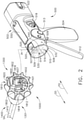
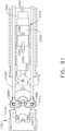
- FIG. 1 depicts one form of an interchangeable surgical tool assembly 1000 that is operably coupled to a motor driven handle assembly 500.
- the interchangeable surgical tool assembly 1000 may also be effectively employed with a tool drive assembly of a robotically controlled or automated surgical system.
- the surgical tool assemblies disclosed herein may be employed with various robotic systems, instruments, components and methods such as, but not limited to, those disclosed in U.S. Patent No. 9,072,535 , entitled SURGICAL STAPLING INSTRUMENTS WITH ROTATABLE STAPLE DEPLOYMENT ARRANGEMENTS.
- the handle assembly 500, as well as the tool drive assembly of a robotic system may also be referred to herein as "control systems" or "control units".
- FIG. 2 illustrates attachment of the interchangeable surgical tool assembly 1000 to the handle assembly 500.
- the handle assembly 500 may comprise a handle housing 502 that includes a pistol grip portion 504 that can be gripped and manipulated by the clinician.
- the handle assembly 500 may further include a frame 506 that operably supports the plurality of drive systems.
- the frame 506 can operably support a "first" or closure drive system, generally designated as 510, which may be employed to apply closing and opening motions to the interchangeable surgical tool assembly 1000 that is operably attached or coupled to the handle assembly 500.
- the closure drive system 510 may include an actuator in the form of a closure trigger 512 that is pivotally supported by the frame 506.
- the closure drive system 510 further includes a closure linkage assembly 514 that is pivotally coupled to the closure trigger 512 or otherwise operably interfaces therewith.
- the closure linkage assembly 514 includes a transverse attachment pin 516 that facilitates attachment to a corresponding drive system on the surgical tool assembly.
- the clinician depresses the closure trigger 512 towards the pistol grip portion 504.
- the closure drive system 510 is configured to lock the closure trigger 512 into the fully depressed or fully actuated position.
- closure release button assembly 518 When the clinician desires to unlock the closure trigger 512 to permit it to be biased to the unactuated position, the clinician simply activates a closure release button assembly 518 which enables the closure trigger 512 to return to the unactuated position.
- the closure release button assembly 518 may also be configured to interact with various sensors that communicate with a microcontroller 520 in the handle assembly 500 for tracking the position of the closure trigger 512. Further details concerning the configuration and operation of the closure release button assembly 518 may be found in U.S. Patent Application Publication No. 2015/0272575 .
- the handle assembly 500 and the frame 506 may operably support another drive system referred to herein as a firing drive system 530 that is configured to apply axial or firing motions to corresponding portions of the interchangeable surgical tool assembly that is attached thereto.
- the firing drive system 530 may employ an electric motor 505 that is located in the pistol grip portion 504 of the handle assembly 500.
- the motor 505 may be a DC brushed driving motor having a maximum rotation of, approximately, 25,000 RPM, for example.
- the motor 505 may include a brushless motor, a cordless motor, a synchronous motor, a stepper motor, or any other suitable electric motor.
- the motor 505 may be powered by a power source 522 that in one form may comprise a removable power pack.
- the power pack may support a plurality of Lithium Ion ("LI") or other suitable batteries therein. A number of batteries may be connected in series may be used as the power source 522 for the handle assembly 500.
- the power source 522 may be replaceable and/or rechargeable.
- the electric motor 505 is configured to axially drive a longitudinally movable drive member 540 in distal and proximal directions depending upon the polarity of the motor. For example, when the motor 505 is driven in one rotary direction, the longitudinally movable drive member 540 will be axially driven in the distal direction "DD". When the motor 505 is driven in the opposite rotary direction, the longitudinally movable drive member 540 will be axially driven in a proximal direction "PD”.
- the handle assembly 500 can include a switch 513 which can be configured to reverse the polarity applied to the electric motor 505 by the power source 522 or otherwise control the motor 505.
- the handle assembly 500 can also include a sensor or sensors (not shown) that is configured to detect the position of the drive member 540 and/or the direction in which the drive member 540 is being moved.
- Actuation of the motor 505 can be controlled by a firing trigger 532 that is pivotally supported on the handle assembly 500.
- the firing trigger 532 may be pivoted between an unactuated position and an actuated position.
- the firing trigger 532 may be biased into the unactuated position by a spring (not shown) or other biasing arrangement such that when the clinician releases the firing trigger 532, it may be pivoted or otherwise returned to the unactuated position by the spring or biasing arrangement.
- the firing trigger 532 can be positioned "outboard" of the closure trigger 512 as was discussed above.
- the handle assembly 500 may be equipped with a firing trigger safety button (not shown) to prevent inadvertent actuation of the firing trigger 532.
- a firing trigger safety button (not shown) to prevent inadvertent actuation of the firing trigger 532.
- the safety button is contained in the handle assembly 500 where the clinician cannot readily access it and move it between a safety position preventing actuation of the firing trigger 532 and a firing position wherein the firing trigger 532 may be fired.
- the safety button and the firing trigger 532 may pivot down wherein they can then be manipulated by the clinician.
- the longitudinally movable drive member 540 may have a rack of teeth (not shown) formed thereon for meshing engagement with a corresponding drive gear arrangement (not shown) that interfaces with the motor 505. Further details regarding those features may be found in U.S. Patent Application Publication No. 2015/0272575 .
- At least one form also includes a manually-actuatable "bailout" assembly that is configured to enable the clinician to manually retract the longitudinally movable drive member 540 should the motor 505 become disabled.
- the bailout assembly may include a lever or bailout handle assembly that is stored within the handle assembly 500 under a releasable door 550. The lever is configured to be manually pivoted into ratcheting engagement with the teeth in the drive member 540.
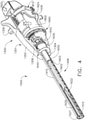
- the interchangeable surgical tool assembly 1000 includes a shaft mounting portion 1300 that is operably attached to an elongate shaft assembly 1400.
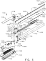
- a surgical end effector 1100 that comprises an elongate channel 1102 that is configured to operably support a surgical staple cartridge 1150 therein is operably attached to the elongate shaft assembly 1400. See FIGS. 3 and 6 .
- the surgical end effector 1100 may further include an anvil 1130 that is pivotally supported relative to the elongate channel 1102.
- the elongate channel 1102 with a staple cartridge 1150 installed therein and the anvil 1130 may also be referred to as the end effector "jaws".
- the interchangeable surgical tool assembly 1000 may further include an articulation joint 1200 and an articulation lock 1210 ( FIGS. 3 and 6 ) which can be configured to releasably hold the surgical end effector 1100 in a desired articulated position about an articulation axis B-B which is transverse to a shaft axis SA.
- an articulation lock 1210 FIGS. 3 and 6
- Many details regarding the construction and operation of the articulation lock 1210 may be found in in U.S. Patent Application Serial No. 13/803,086 , entitled ARTICULATABLE SURGICAL INSTRUMENT COMPRISING AN ARTICULATION LOCK, now U.S. Patent
- the shaft mounting portion 1300 includes a proximal housing or nozzle 1301 comprised of nozzle portions 1302, 1304 as well as an actuator wheel portion 1306 that is configured to be coupled to the assembled nozzle portions 1302, 1304 by snaps, lugs, screws, etc.
- the interchangeable surgical tool assembly 1000 further includes a closure assembly 1406 which can be utilized to close and/or open the anvil 1130 relative to the elongate channel 1102 of the surgical end effector 1100 as will be discussed in further detail below.
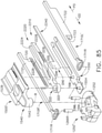
- the illustrated interchangeable surgical tool assembly 1000 includes a spine assembly 1500 which operably supports the articulation lock 1210.
- the spine assembly 1500 is configured to, one, slidably support a firing member assembly 1600 therein and, two, slidably support the closure assembly 1406 which extends around the spine assembly 1500 or is otherwise movably supported thereby.
- the surgical end effector 1100 is operably coupled to the elongate shaft assembly 1400 by an articulation joint 1200 that facilitates selective articulation of the surgical end effector 1100 about an articulation axis B-B that is transverse to the shaft axis SA. See FIG. 1 .
- the spine assembly 1500 slidably supports a proximal articulation driver 1700 that operably interfaces with an articulation lock 1210.
- the articulation lock 1210 is supported on a distal frame segment 1560 that also comprises a portion of the spine assembly 1500. As can be seen in FIG.
- the distal frame segment 1560 comprises a distal spine extension 1562 that is pivotally coupled to the elongate channel 1102 by an end effector mounting assembly 1230.
- a distal end 1563 of the distal frame segment 1560 has a spine attachment pin 1564 formed thereon.
- the spine attachment pin 1564 is adapted to be pivotally received within a spine attachment hole 1234 that is formed in the end effector mounting assembly 1230. See FIG. 6 .
- the proximal articulation driver 1700 has a distal end 1702 that is configured to operably engage the articulation lock 1210.
- the articulation lock 1210 includes an articulation frame 1212 that is pivotally coupled or pinned to a distal articulation link 1710 that is also configured to be pivotally attached to the end effector mounting assembly 1230.
- a distal end 1712 of the distal articulation link 1710 includes an articulation pin 1714 that is configured to be pivotally received within corresponding articulation holes 1236 in the end effector mounting assembly 1230.
- the distal articulation link 1710 is slidably supported by the distal spine extension 1562.
- the end effector mounting assembly 1230 is attached to a proximal end 1103 of the elongate channel 1102 by a spring pin connector 1235 that extends through a transverse mounting hole 1231 in the end effector mounting assembly 1230 to be received within channel or jaw mounting holes 1106 that are provided in the proximal end 1103 of the elongate channel 1102.
- the spine attachment pin 1564 defines an articulation axis B-B that is transverse to the shaft axis SA. Such arrangement facilitates pivotal travel (i.e., articulation) of the surgical end effector 1100 about the articulation axis B-B relative to the spine assembly 1500.
- the spine assembly 1500 further comprises an intermediate spine segment 1510 that is attached to the distal frame segment 1560 of the articulation lock 1210.
- the spine assembly 1500 further comprises a proximal spine mounting segment 1530 that includes a proximal end portion 1532 that has opposing notches 1535 (only one can be seen in FIG. 5 ) for receiving a corresponding mounting lug 1308 (shown in FIG. 4 ) that protrude inwardly from each of the nozzle portions 1302, 1304.
- Such arrangement facilitates rotation of the proximal spine assembly 1500 about the shaft axis SA by rotating the nozzle 1301 about the shaft axis SA.
- the interchangeable surgical tool assembly 1000 includes a chassis 1800 that rotatably supports the shaft assembly 1400.
- the proximal end portion 1532 of the proximal spine mounting segment is rotatably supported in a central shaft hole 1801 that is formed in the chassis 1800. See FIG. 5 .
- the proximal end portion 1532 has threads 1533 thereon for attachment to a spine bearing (not shown) or other wise supported in a spine bearing that is mounted within the chassis 1800.
- Such an arrangement facilitates rotatable attachment of the spine assembly 1500 to the chassis 1800 such that the spine assembly 1500 may be selectively rotated about a shaft axis SA relative to the chassis 1800.
- the closure assembly 1406 comprises an elongate proximal closure member 1410 and a distal closure member 1430.
- the proximal closure member 1410 comprises a hollow tubular member that is slidably supported on the spine assembly 1500.
- the proximal closure member 1410 may also be referred to herein as the "proximal closure tube”.
- the distal closure member 1430 may also be referred to as the "distal closure tube”.
- the interchangeable surgical tool assembly 1000 includes a closure shuttle 1420 that is slidably supported within the chassis 1800 such that it may be axially moved relative thereto.
- the closure shuttle 1420 includes a pair of proximally-protruding hooks 1421 that are configured for attachment to the transverse attachment pin 516 ( FIG. 2 ) that is attached to the closure linkage assembly 514 of the handle assembly 500.
- a closure spring (not shown) may also be journaled on the closure assembly 1406 and serves to bias the closure assembly 1406 in the proximal direction "PD" which can serve to pivot the closure trigger 512 into the unactuated position when the surgical tool assembly 1000 is operably coupled to the handle assembly 500.
- the closure assembly 1406 is translated distally (direction DD) to close the jaws 1130, 1102 for example, in response to the actuation of the closure trigger 512.
- the closure linkage assembly 514 may also be referred to herein as a "closure actuator” and the closure linkage assembly 514 and the closure shuttle 1420 may be collectively referred to herein as a "closure actuator assembly”.
- a proximal end 1412 of the proximal closure member 1410 is coupled to the closure shuttle 1420 for relative rotation thereto.
- a U-shaped connector 1424 is inserted into an annular slot 1414 in the proximal end 1412 of the proximal closure member 1410 and is retained within vertical slots 1422 in the closure shuttle 1420. See FIG. 5 .
- Such arrangement serves to attach the proximal closure member 1410 to the closure shuttle 1420 for axial travel therewith while enabling the closure assembly 1406 to rotate relative to the closure shuttle 1420 about the shaft axis SA.
- the illustrated interchangeable surgical tool assembly 1000 includes an articulation joint 1200.
- upper and lower tangs 1415, 1416 protrude distally from a distal end of the proximal closure member 1410 to be movably coupled to the distal closure member 1430.
- the distal closure member 1430 includes upper and lower tangs 1434, 1436 that protrude proximally from a proximal end thereof. The proximal closure member 1410 and the distal closure member 1430 are coupled together by an upper double pivot link 1220.
- the upper double pivot link 1220 includes proximal and distal pins that engage corresponding holes in the upper tangs 1415, 1434 of the proximal closure member 1410 and distal closure member 1430, respectively.
- the proximal closure member 1410 and the distal closure member 1430 are also coupled together by a lower double pivot link 1222.
- the lower double pivot link 1222 includes proximal and distal pins that engage corresponding holes in the lower tangs 1416 and 1436 of the proximal closure member 1410 and distal closure member 1430, respectively.
- distal and proximal axial translation of the closure assembly 1406 will result in the closing and opening of the anvil 1130.
- the interchangeable surgical tool assembly 1000 depicted in FIGS. 1-6 includes a surgical end effector 1100 that is capable of articulating about the articulation axis B-B in one direction.
- the articulation axis B-B is defined by the spine attachment pin 1564 that is rotatably received within the spine attachment hole 1234 that is formed in the end effector mounting assembly 1230.
- the spine attachment hole 1234 may be transversely axially aligned with the shaft axis SA. In other arrangements, the spine attachment hole 1234 may be slightly laterally offset from the shaft axis.
- the articulation axis B-B is transverse to and intersects the shaft axis SA.
- the illustrated example only employs a proximal articulation driver 1700 that interfaces with a single distal articulation link 1710 (through the articulation lock 1210) that operably interfaces with the end effector mounting assembly 1230 to apply articulation motions thereto.
- a proximal articulation driver 1700 that interfaces with a single distal articulation link 1710 (through the articulation lock 1210) that operably interfaces with the end effector mounting assembly 1230 to apply articulation motions thereto.
- distally advancing the distal articulation link 1710 will cause the surgical end effector 1100 to articulate in a single "first" articulation direction.
- the surgical end effector 1100 may be selectively articulatable from a first unarticulated position wherein the surgical end effector 1100 is axially aligned with the shaft assembly 1400 (for insertion through a trocar or other access opening) through an articulation angle of approximately 110° (after the surgical end effector 1100 has exited the trocar into the patient).
- Other articulation angle arrangements may be achieved.
- the interchangeable surgical tool assembly 1000 may be well-suited for use in connection with a medical procedure known as a lower anterior resection "LAR".
- LAR lower anterior resection
- Such procedure commonly involves removal of a diseased portion of the colon.
- this procedure may comprise removal of the blood vessels and lymph nodes associated with this portion of the bowel.
- the surgeon then re-joins the remaining colon and the remaining part of the rectum (which may be referred to as an anastomosis).
- One challenge commonly facing the surgeon during this procedure is associated with getting the end effector into the pelvic area far enough to complete the procedure.
- FIG. 7 illustrates a desired position of the surgical end effector 1100 within the pelvis 400 of a patient during the resection of the patient's colon 410.
- Lines BTL in FIG. 7 may illustrate travel limits commonly created by the patient's pelvic bone structure and associated tissue.
- the surgical tool assembly 1000 employs an "asymmetric" proximal closure member 1410 that is configured to provide additional clearance and maneuverability for the surgical tool assembly 1000 within that region.
- the proximal closure member 1410 of the shaft assembly 1400 includes an elongate proximal end portion 1417 and an elongate distal end portion 1411 that extends from the proximal end portion 1417.
- an asymmetric cut out or notched area 1418 is provided in the distal end portion 1411 of the proximal closure member 1410.
- the notched area 1418 extends for the entire distal end portion 1411. In such arrangement, an axial length of the distal end portion is less than an axial length of the proximal end portion 1417.
- the proximal end portion 1417 has an uninterrupted or “continuous" "proximal” outer perimeter or perimetrical shape 1417P. At least a portion of the distal end portion 1411 has a discontinuous or interrupted “distal" outer perimeter or outer perimetrical shape 1411P.
- the distal spine extension 1562 has a similar notched area 1568 therein.
- the intermediate spine segment 1510 may also have an asymmetric notch 1516 therein that matches the notched areas 1418 and 1568. See FIGS. 10 and 11 . Such arrangement may permit the clinician to position the shaft assembly 1400 and the surgical end effector 1100 into the position shown in FIG.
- the articulation angle AA may be approximately 110°.
- the notched areas 1418, 1516, 1568 are located on the opposite side of the shaft axis SA from which the end effector 1100 articulates (e.g., direction of articulation DA). In other arrangements, however, it is conceivable that the notched areas 1418, 1516, 1568 are provided on the same side of the shaft axis SA from which the surgical end effector articulates.
- opposed closure alignment members 1413 are employed.
- a pair of diametrically-opposed alignment pins 1413 are attached to and extend inwardly from the proximal closure member 1410 to be slidably received within corresponding alignment slots 1514, 1566 in the intermediate spine segment 1510 and the distal spine extension 1562, respectively. See FIGS. 10 and 11 . As can also be seen in FIG.
- the distal spine extension 1562 may have a recessed area 1567 for receiving a downwardly protruding lug portion 1518 that is formed on the underside of the intermediate spine segment 1510. Such arrangement may serve to somewhat laterally interlock the intermediate spine segment 1510 and the distal spine extension 1562 together to thereby resist any lateral deflection from occurring between those components.
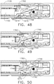
- FIG. 12 illustrates an alternative proximal closure member 1410' that is identical to the proximal closure member 1410 described above, except that the proximal closure member 1410' includes a connector bridge 1419 that extends between the upper and lower tangs 1415 and 1416 which may serve to limit any tendency of the upper and lower tangs 1415, 1416 from spreading apart during use.
- FIG. 13 illustrates another arrangement that is configured to prevent or limit the opening of a proximal closure member 1410" in the directions OD when a lateral load LL is applied laterally to the shaft assembly 1400 in the notched areas.
- the proximal closure member 1410" may be identical to proximal closure member 1410 except for the differences noted herein.
- the proximal closure member 1410" additionally includes a pair of inwardly protruding, somewhat diametrically opposed flexure tabs 1425.
- One flexure tab 1425 is slidably received within a corresponding axially extending slot 1519 and the other flexure tab 1425 is slidably received within a corresponding axial slot 1569 in the distal spine extension 1562.
- Such arrangement serves to slidably interlock the proximal closure member 1410" on the spine assembly 1500' to thereby cause the proximal closure member 1410" to resist opening (in the OD directions) when a lateral load LL is applied thereto.
- FIG. 14 illustrates an alternative arrangement that employs flexure tabs 1425' are somewhat L-shaped and are slidably received within corresponding L-shaped slots 1514' and 1569'.
- the interchangeable surgical tool assembly 1000 further includes a firing member assembly 1600 that is supported for axial travel within the spine assembly 1500.
- the firing member assembly 1600 includes a proximal firing shaft segment 1602 and a distal cutting portion or distal firing bar 1620.
- the firing member assembly 1600 may also be referred to herein as a "second shaft” and/or a "second shaft assembly”.
- the proximal firing shaft segment 1602 includes a proximal attachment lug 1604 that protrudes proximally from a proximal end thereof that is configured to be operably received within the firing shaft attachment cradle 542 in the longitudinally movable drive member 540 that is supported in the handle assembly 500. See FIG. 2 .
- a distal end 1606 of the proximal firing shaft segment 1602 includes a longitudinal slot 1608 which is configured to receive a tab (not shown) on the proximal end of the distal firing bar 1620.
- the longitudinal slot 1608 and the proximal end of the distal firing bar 1620 can be sized and configured to permit relative movement therebetween and can comprise a slip joint 1622.
- the slip joint 1622 can permit the proximal firing shaft segment 1602 to move during the articulation actuation without moving, or at least substantially moving, the distal firing bar 1620.
- the proximal firing shaft segment 1602 can be advanced distally until a proximal end wall of the slot 1608 comes into contact with the tab on the distal firing bar 1620 to advance the distal firing bar 1620 and fire the surgical staple cartridge 1150 that is positioned within the elongate channel 1102.
- the intermediate spine segment 1510 includes a channel 1512 for slidably supporting the proximal firing shaft segment 1602 therein.
- a top spine cover 1527 may be engaged with the intermediate spine segment 1510 to enclose those portions of the firing member assembly 1600 therein.
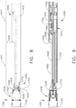
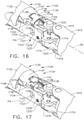
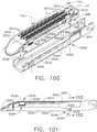
- FIG. 15 illustrates the surgical end effector 1100 in an articulated position.
- a middle support member 1614 is employed to provide lateral support to the distal firing bar 1620 as it flexes to accommodate articulation of the surgical end effector 1100.
- a distal pivot pin 1615 protrudes from a distal end of the middle support member 1614 and is received within a spine attachment hole 1234 in the end effector mounting assembly 1230.
- a proximal pivot pin 1616 is received within an elongate slot 1569 in the distal spine extension 1562.
- middle support member 1614 includes a passageway 1618 therein that provides lateral support to the distal firing bar 1620 as the surgical end effector 1100 is articulated. Further details concerning the middle support member and alternative knife bar support arrangements are disclosed in U.S. Patent Application Serial No. 15/019,245 .
- FIG. 15A illustrates an alternative articulation joint 1200' that facilitates articulation of the surgical end effector 1100 about an articulation axis B-B that is transverse to a shaft axis SA that is defined by the elongate shaft assembly 1400' to which it is operably attached.
- the surgical end effector 1100 is selectively articulatable to one side of the shaft axis SA.
- Such articulation direction is represented by arrow LD.
- an end effector mounting assembly 1230 is pivotally attached to a proximal end 1103 of an elongate channel 1102 of the surgical end effector 1100.
- the end effector mounting assembly 1230 is pivotally attached to a distal spine extension 1562 of a distal frame segment 1560 of the elongate shaft assembly 1400'. Similar to the above described embodiment, the distal frame segment 1560 may operably support an articulation lock 1210 ( FIG. 6 ) that is actuated by a proximal articulation driver 1700 ( FIG. 6 ) that operably interfaces with a source of articulation and retraction motions as described in detail herein. In the example illustrated in FIG. 15A , the end effector mounting assembly 1230 is pivotally attached to the distal spine extension 1562 by a distal support link 1570.
- the end effector mounting assembly 1230 is pinned to a distal end 1572 of the distal support link 1570 by an articulation pin 1580 that defines the articulation axis B-B.
- a proximal end 1574 of the distal support link 1570 is attached to a distal end 1563 of the distal spine extension 1562 for axial and pivotal travel relative thereto.
- the proximal end 1574 of the distal support link 1570 includes an axial slot 1576 that is sized to slidably and pivotally receive therein a proximal attachment pin 1578 that is attached to the distal spine extension 1562.
- Such arrangement serves to couple the surgical end effector 1100 to the distal frame segment 1560 for selective pivotal travel (articulation) about the articulation axis B-B as well as some limited axial travel relative thereto.
- articulation motions are applied to the surgical end effector 1100 by a distal articulation link 1710 that is pivotally coupled to or otherwise operably interfaces with the articulation lock 1210.
- Axial movement of the distal articulation link 1710 in the proximal direction PD (which is constrained to move axially along one side of the shaft axis SA), will cause the surgical end effector 1100 to articulate in the left direction LD from an unarticulated position wherein the surgical end effector 1100 is axially aligned on the shaft axis SA to articulated positions on the left side of the shaft axis SA (represented in phantom lines in FIG 15A ).
- Axial movement of the distal articulation link 1710 in the distal direction DD will move the surgical end effector 1100 from an articulated position towards the unactuated position (arrow RD).
- a stop member or stop formation 1232 is formed or otherwise attached to the end effector mounting assembly 1230 to contact the distal end 1563 of the distal spine extension when the surgical end effector 1100 has attained the unactuated position to prevent any further travel thereof in the right direction RD.
- Such articulation joint arrangement may provide improved articulation travel and closure stability.
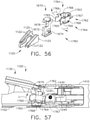
- the interchangeable surgical tool assembly 1000 includes a clutch assembly 1640 which can be configured to selectively and releasably couple the proximal articulation driver 1700 to the firing member assembly 1600.
- the clutch assembly 1640 includes a rotary lock assembly that, in at least one embodiment, comprises a lock collar, or lock sleeve 1650 that is positioned around the firing member assembly 1600.
- the lock sleeve 1650 is configured to be rotated between an engaged position in which the lock sleeve 1650 couples the proximal articulation driver 1700 to the firing member assembly 1600 and a disengaged position in which the proximal articulation driver 1700 is not operably coupled to the firing member assembly 1600.
- proximal articulation driver 1700 When lock sleeve 1650 is in its engaged position, distal movement of the firing member assembly 1600 can move the proximal articulation driver 1700 distally and, correspondingly, proximal movement of the firing member assembly 1600 can move the proximal articulation driver 1700 proximally.
- lock sleeve 1650 When lock sleeve 1650 is in its disengaged position, movement of the firing member assembly 1600 is not transmitted to the proximal articulation driver 1700 and, as a result, the firing member assembly 1600 can move independently of the proximal articulation driver 1700.
- the proximal articulation driver 1700 can be held in position by the articulation lock 1210 when the proximal articulation driver 1700 is not being moved in the proximal or distal directions by the firing member assembly 1600.
- the lock sleeve 1650 comprises a cylindrical, or an at least substantially cylindrical, body that includes a longitudinal aperture 1652 that is configured to receive the proximal firing shaft segment 1602 of the firing member assembly 1600.
- the lock sleeve 1650 also has two diametrically-opposed, inwardly-facing lock protrusions 1654 and an outwardly protruding second lock member 1656 formed thereon.
- the lock protrusions 1654 can be configured to be selectively engaged with the proximal firing shaft segment 1602 of the firing member assembly 1600.
- the lock protrusions 1654 are positioned within a drive notch 1603 that is provided in the proximal firing shaft segment 1602 such that a distal pushing force and/or a proximal pulling force can be transmitted from the firing member assembly 1600 to the lock sleeve 1650.
- the second lock member 1656 is received within a drive notch 1704 that is defined in the proximal articulation driver 1700 such that the distal pushing force and/or the proximal pulling force applied to the lock sleeve 1650 can be transmitted to the articulation driver 1700.
- the firing member assembly 1600, the lock sleeve 1650, and the proximal articulation driver 1700 will move together when the lock sleeve 1650 is in its engaged position.
- the lock protrusions 1654 may not be positioned within the drive notch 1603 of the proximal firing shaft segment 1602 of the firing member assembly 1600 and, as a result, a distal pushing force and/or a proximal pulling force may not be transmitted from the firing member assembly 1600 to the lock sleeve 1650.
- the distal pushing force and/or the proximal pulling force may not be transmitted to the proximal articulation driver 1700.
- the firing member assembly 1600 can be slid proximally and/or distally relative to the lock sleeve 1650 and the proximal articulation driver 1700.
- the clutch assembly 1640 further includes a switch drum 1630 that interfaces with the lock sleeve 1650. Further details concerning the operation of the switch drum 1630 and lock sleeve 1650 may be found in U.S. Patent Application Serial No. 13/803,086 and U.S. Patent Application Serial No. 15/019,196 .
- the switch drum 1630 can further comprise at least partially circumferentially extending openings 1632 defined therein which can receive circumferential mounts 1305 that extend from the nozzle portions 1302, 1304 and permit relative rotation, but not translation, between the switch drum 1630 and the proximal nozzle 1301. See FIG. 6 .
- Rotation of the nozzle 1301 to a point where the mounts reach the end of their respective openings 1632 in the switch drum 1630 will result in rotation of the switch drum 1630 about the shaft axis SA. Rotation of the switch drum 1630 will ultimately result in the movement of the lock sleeve 1650 between its engaged and disengaged positions.
- the nozzle 1301 may be employed to operably engage and disengage the articulation drive system with the firing drive system.
- clutch assembly 1640 may operate in the various manners described in further detail in U.S. Patent Application Serial No. 13/803,086 and U.S. Patent Application Serial No. 15/019,196 .
- the switch drum 1630 includes an L-shaped slot 1636 that extends into a distal opening 1637 in the switch drum 1630.
- the distal opening 1637 receives a transverse switch pin 1639 of a shifter plate 1638.
- the shifter plate 1638 is received within a longitudinal slot (not shown) that is provided in the lock sleeve 1650 to facilitate axial movement of the lock sleeve 1650 when engaged with the proximal articulation driver 1700.
- Further details regarding the operation of the shifter plate and shift drum arrangements may be found in U.S. Patent Application Serial No. 14/868,718, filed September 28, 2015 , entitled SURGICAL STAPLING INSTRUMENT WITH SHAFT RELEASE, POWERED FIRING AND POWERED ARTICULATION.
- the switch drum 1630 includes a magnet support arm 1665 that supports a magnet or other sensor arrangement that is configured to operably interface with a Hall effect sensor 1662 that interfaces with a slip ring assembly 1660 that is operably mounted to the chassis 1800.
- the slip ring assembly 1660 is configured to conduct electrical power to and/or from the interchangeable surgical tool assembly 1000 and/or communicate signals to and/or from the interchangeable surgical tool assembly 1000 components back to the microcontroller 520 in the handle assembly 500 ( FIG. 2 ) or robotic system controller, for example. Further details concerning the slip ring assembly 1660 and associated connectors may be found in U.S. Patent Application Serial No. 13/803,806 and U.S. Patent Application Serial No. 15/019,196 as well as in U.S.
- Patent Application Serial No. 13/800,067 entitled STAPLE CARTRIDGE TISSUE THICKNESS SENSOR SYSTEM, now U.S. Patent Application Publication No. 2014/0263552 .
- the magnet or magnets supported on the magnet support arm 1665 cooperate with the Hall effect sensor 1662 or other sensor arrangement to detect the rotary position of the switch drum 1630 and convey that information to the microcontroller 520 which may serve to provide an indication or indications to the user in the various manners discussed in the aforementioned incorporated references.
- Other sensor arrangements may also be employed.
- the chassis 1800 includes at least one, and preferably two, tapered attachment portions 1802 that are formed thereon and are adapted to be received within corresponding dovetail slots 507 that are formed within the distal end portion of the frame 506 of the handle assembly 500.
- a shaft attachment lug 1607 is formed on the proximal end of the proximal firing shaft segment 1602.
- the shaft attachment lug 1607 is received in a firing shaft attachment cradle 542 that is formed in the distal end of the longitudinally movable drive member 540. See FIG. 2 .
- the interchangeable surgical tool assembly 1000 employs a latch system 1810 for removably coupling the interchangeable surgical tool assembly 1000 to the frame 506 of the handle assembly 500.
- the latch system 1810 includes a lock member or lock yoke 1812 that is movably coupled to the chassis 1800.
- the lock yoke 1812 has a U-shape and includes two downwardly extending legs 1814.
- the legs 1814 each have a pivot lug (not shown) formed thereon that is adapted to be received in corresponding holes 1816 that are formed in the chassis 1800.
- Such arrangement facilitates pivotal attachment of the lock yoke 1812 to the chassis 1800.
- the lock yoke 1812 may include two proximally protruding lock lugs 1818 that are configured for releasable engagement with corresponding lock detents or grooves 509 in the distal end of the frame 506 of the handle assembly 500. See FIG. 2 .
- the lock yoke 1812 is biased in the proximal direction by a spring or biasing member 1819. Actuation of the lock yoke 1812 may be accomplished by a latch button 1820 that is slidably mounted on a latch actuator assembly 1822 that is mounted to the chassis 1800.
- the latch button 1820 may be biased in a proximal direction relative to the lock yoke 1812.
- the lock yoke 1812 may be moved to an unlocked position by biasing the latch button 1820 in the distal direction which also causes the lock yoke 1812 to pivot out of retaining engagement with the distal end of the frame 506.
- the lock lugs 1818 are retainingly seated within the corresponding lock detents or grooves 509 in the distal end of the frame 506.
- the lock yoke 1812 includes at least one and preferably two lock hooks 1824 that are adapted to contact corresponding lock lug portions 1426 that are formed on the closure shuttle 1420.
- the lock yoke 1812 may be pivoted in a distal direction to unlock the interchangeable surgical tool assembly 1000 from the handle assembly 500.
- the lock hooks 1824 do not contact the lock lug portions 1426 on the closure shuttle 1420.
- the lock yoke 1812 is prevented from being pivoted to an unlocked position.
- the clinician may position the chassis 1800 of the interchangeable surgical tool assembly 1000 above or adjacent to the distal end of the frame 506 such that the tapered attachment portions 1802 formed on the chassis 1800 are aligned with the dovetail slots 507 in the frame 506.
- the clinician may then move the surgical tool assembly 1000 along an installation axis IA that is perpendicular to the shaft axis SA to seat the tapered attachment portions 1802 in "operable engagement" with the corresponding dovetail receiving slots 507 in the distal end of the frame 506.
- the shaft attachment lug 1606 on the proximal firing shaft segment 1602 will also be seated in the cradle 542 in the longitudinally movable drive member 540 and the portions of the transverse attachment pin 516 on the closure linkage assembly 514 will be seated in the corresponding hooks 1421 in the closure shuttle 1420.
- operble engagement in the context of two components means that the two components are sufficiently engaged with each other so that upon application of an actuation motion thereto, the components may carry out their intended action, function and/or procedure.
- the distal firing bar 1620 may comprise a laminated beam structure that includes at least two beam layers.
- Such beam layers may comprise, for example, stainless steel bands that are interconnected by, for example, welding or pinning together at their proximal ends and/or at other locations along their length.
- the distal ends of the bands are not connected together to allow the laminates or bands to splay relative to each other when the end effector is articulated.
- Such arrangement permits the distal firing bar 1620 to be sufficiently flexible to accommodate articulation of the end effector.
- Various other suitable laminated knife bar arrangements are disclosed in U.S. Patent Application Serial No. 15/019,245 . As can also be seen in FIG.
- a middle support member 1614 is employed to provide lateral support to the distal firing bar 1620 as it flexes to accommodate articulation of the surgical end effector 1100. Further details concerning the middle support member and alternative knife bar support arrangements are disclosed in U.S. Patent Application Serial No. 15/019,245 .
- the clinician may operate the surgical tool assembly 1000 as follows.
- a torsion spring 1642 has biased the clutch assembly 1640 and, more particularly, the switch pin 1639 and the lock sleeve 1650 into the articulation position.
- the magnet or magnets in the magnet support arm 1665 may cooperate with the Hall effect sensor 1662 or other sensor arrangements as to indicate to the microcontroller 520 that the surgical tool assembly 1000 is in the articulation mode.
- the motor drives the proximal firing shaft segment 1602 distally.
- the slip joint 1622 facilitates movement of the proximal firing shaft segment 1602 without moving, or at least substantially moving, the distal firing bar 1620. Because the lock sleeve 1650 is in operable engagement with the proximal firing shaft segment 1602 and the proximal articulation driver 1700 is in engagement with the lock sleeve 1650, actuation of the proximal firing shaft segment 1602 results in the distal movement of the proximal articulation driver 1700.
- Distal movement of the proximal articulation driver 1700 causes the surgical end effector 1100 to articulate around the articulation axis B-B.
- the clinician can also partially close the jaws of the surgical end effector 1100 by partially depressing the closure trigger.
- Such arrangement facilitates axial movement of the proximal closure member 1410 without automatically shifting the clutch assembly 1640 to the firing mode. This feature may enable the clinician to use the jaws to grasp and manipulate tissue prior to clamping onto the target tissue.
- the clinician releases the firing trigger 532 which will discontinue the motorized movement of the proximal firing shaft segment 1602 as well as the proximal articulation driver 1700.
- the articulation lock 1210 will lock the proximal articulation driver 1700 in that position to prevent further articulation of the surgical end effector 1100.
- the clinician may clamp the target tissue between the jaws by depressing the closure trigger 512 to the fully depressed position. Such action moves the proximal closure member 1410 distally.
- proximal closure member 1410 causes the shifter plate 1638 to rotate the lock sleeve 1650 to rotate to a disengaged position with the proximal firing shaft segment 1602.
- the lock protrusions 1654 have disengaged from the drive notch 1603 in the proximal firing shaft segment 1602.
- the proximal firing shaft segment 1602 can move axially without moving the lock sleeve 1650 and the proximal articulation driver 1700.
- the proximal closure member 1410 is moved distally to the fully actuated position (by depressing the closure trigger 512), the proximal and distal closure members 1410 and 1430 move distally to close the jaws 1130, 1102.
- the closure drive system 510 in the handle assembly 500 may be locked and the clinician can release the closure trigger 512.
- the clutch assembly 1640 has been moved to this firing mode, the magnet or other sensors in the magnet support arm 1665 or other portion is in communication with the Hall effect sensor 1662 to indicate the position of the clutch assembly 1640 to the microcontroller 520.
- the microcontroller 520 may provide the clinician with an indication of the position of the distal firing bar 1620 as it is advanced distally through the target tissue that is clamped between the end effector jaws. Once the distal firing bar 1620 and, more specifically, the firing member or knife member attached thereto has been advanced to a fully fired position, the microcontroller 520, by means of sensor arrangements, detects the position of a portion of the firing member assembly 1600 and may then reverse the motor to retract the distal firing bar 1620 to its starting position. This action may be automatic or the clinician may have to depress the firing trigger 532 during the retraction process.
- the microcontroller 520 may provide the clinician with an indication that the distal firing bar 1620 has been fully retracted and the closure trigger 512 may be unlocked to enable the closure assembly 1406 to be returned to the unactuated position which thereby moves the jaws to the open position.
- the elongate channel 1102 is roughly C-shaped with two upstanding sidewall portions 1104.
- the anvil 1130 includes an anvil body portion 1132 and an anvil mounting portion 1134.
- the anvil mounting portion 1134 comprises a pair of anvil mounting walls 1136 that are separated by a slot 1138 ( FIG. 6 ).
- the end effector mounting assembly 1230 is pivotally attached to the proximal end 1103 of the elongate channel 1102 by a spring pin connector 1235 that extends through a transverse mounting hole 1231 in the end effector mounting assembly 1230 to be received within channel mounting holes 1106 provided in the sidewalls 1104 of the elongate channel 1102.
- Each of the anvil mounting walls 1136 has an anvil trunnion 1137 protruding therefrom that are each adapted to be rotatably received within a corresponding anvil mounting hole 1107 in the proximal end 1103 of the elongate channel 1102.
- each of the channel sidewalls 1104 may have a vertical slot or relieved area 1108 that corresponds to each anvil mounting hole 1107 that enables the anvil trunnions 1137 to be vertically dropped into each slot 1108 for ease of assembly.
- the anvil trunnions define a pivot axis PA about which the anvil 1130 is selectively pivotable relative to the elongate channel 1102.
- the pivot axis PA is transverse to the shaft axis SA. See FIG. 16 .
- the elongate channel 1102 is configured to removably support a surgical staple cartridge 1150 therein.
- the surgical staple cartridge 1150 includes a cartridge body 1151 that defines a deck surface 1152 that faces a staple-forming undersurface 1133 of the anvil body portion 1132.
- the cartridge body 1151 has an elongate slot 1154 extending therethrough for permitting the passage of a firing member 1670 that is attached to a distal end of the distal firing bar 1620.
- the cartridge body 1151 has a plurality of anvil pockets 1156 that are serially arranged in lines on both sides of the elongate slot 1154. See FIG. 6 . Housed within these pockets 1156 are staple drivers that operably support one or more surgical staples or fasteners thereon.
- the anvil 1130 may include two downwardly extending tissue stops 1140. See FIG. 18 .
- the tissue stops 1140 when extending downward past the cartridge deck surface 1152 serve to block the target tissue from getting too far proximal between the anvil 1130 and the surgical staple cartridge 1150.
- the anvil mounting walls 1136 are somewhat elongated and extend proximally.
- one or both of the anvil mounting walls 1136 include an opening limiter 1139 ( FIG. 18 ) formed thereon that is configured to contact the end effector mounting assembly 1230 to prevent the anvil 1130 from opening too far. See FIG. 18 .
- Such anvil opening limiter 1139 may prevent the anvil 1130 from being too loose and sloppy on the elongate channel 1102.
- the opening limiter 1139 prevents the anvil 1130 from opening to a position wherein the tissue stops 1140 extend above the cartridge deck surface 1152.
- tissue could be permitted to extend too far proximally between the anvil 1130 and the surgical staple cartridge 1150 and potentially be severed but not stapled.
- Such arrangement may also serve to prevent the anvil from being perceived as being too loose and sloppy relative to the elongate channel.
- the anvil mounting portion 1134 defines a firing member "parking area" 1141 which accommodates the firing member 1670 therein when the firing member 1670 is in a starting (unfired) position.
- the parking area 1141 is proximal to the pivot axis. See, for example, FIG. 19 .
- Such arrangement may reduce the negative moment arm that is created from the tissue that is clamped between the anvil 1130 and the surgical staple cartridge 1150 that is supported in the elongate channel 1102.
- an anvil cap or cover 1142 is attached to the anvil mounting portion 1134 to provide a pre-closure surface 1143 for contact by a distal camming ramp or surface 1440 formed on a distal end 1431 of the distal closure member 1430. See FIG. 20 .
- the anvil cap 1142 includes a pair of downwardly extending legs 1144 that are configured to snappingly engage attachment lugs 1145 that are formed on the anvil mounting walls 1136.
- the anvil cap 1142 includes a distally extending transition portion 1146 that extends between the anvil mounting walls 1136 and covers the firing member 1670 when it is in the firing member parking area 1141.
- the transition portion 1146 extends between the anvil mounting walls 1136 and forms a transition from the pre-closure surface 1143 and an anvil cam surface 1147 formed on the anvil mounting portion 1134.
- the anvil cap 1142 may minimize pinch points that may otherwise be present between the anvil mounting portion 1134 and the distal end 1431 of the distal closure member 1430 when the anvil 1130 is in its fully opened position.
- the anvil body portion 1132 defines an upper anvil surface 1135.
- the cam area or cam surface 1147 that is formed on the anvil mounting portion 1134 gradually transitions to the upper anvil surface 1135.
- the cam surface 1147 comprises two surface portions: a proximal cam surface portion 1147P and a distal cam surface portion 1147D.
- the proximal cam surface portion 1147P extends from a proximal end of the anvil body portion 1132 to the distal cam surface portion 1147D.
- the distal cam surface portion 1147D extends from the proximal cam surface portion 1147P to the upper anvil surface 1135.
- the proximal cam surface portion 1147P may have a slightly steeper angle than the distal cam surface portion 1147D.
- the cam surface on the anvil mounting portion may comprise one continuous cam surface oriented relative to the outer surface at a single cam angle.
- the distal closure member 1430 has a distal end surface 1431 formed on a distal end thereof.
- a distal camming surface 1440 extends at an obtuse cam angle CA relative to the distal end surface 1431.
- the distal closure member 1430 comprises a distal closure tube that has an outer surface 1433 and an inner surface 1435 that defines a cross-sectional thickness CT therebetween.
- the distal end surface 1431 comprises a portion of the cross-sectional thickness CT.
- the distal camming surface 1440 extends from the distal end surface 1431 to the inner surface 1435 of the distal closure member 1430.
- An initial cam area 1437 comprises the line or point of intersection between the distal end surface 1431 and the distal camming surface 1440.
- FIG. 18A illustrates the distal closure member 1430 in a starting position with the anvil 1130 in an open position.
- the distal camming surface 1440 is in contact with the pre-closure surface 1143 on the anvil cap 1142.
- the distal closure member 1430 is axially advanced in the distal direction DD.
- the initial cam area 1437 and/or the distal end surface 1431 initially contacts the cam surface 1147 (proximal cam surface portion 1147P) an initial closure motion or initial closure force ICF is applied thereto. See FIG. 19 .
- This initial closure force ICF is normal or perpendicular to the proximal cam surface portion 1147P.
- distal closure member 1430 With continued axial advancement of the distal closure member 1430 brings the distal camming surface 1440 into camming engagement with the cam surface 1147 (distal cam surface 1147D) and essentially applies a closure force CF that is essentially parallel to the shaft axis SA. See FIG. 20A .
- the anvil mounting walls 1136 may have a length that is somewhat longer than the anvil mounting configurations employed by other anvil arrangements.
- Such elongated anvil mounting walls 1136 serve to enable the pivot axis to be located relatively close to the articulation axis that is defined by the articulation joint 1200.
- This arrangement facilitates establishment of a longer initial moment arm MAI ( FIG. 19 ) between the pivot axis PA and the initial closure force ICF.
- Such arrangement also facilitates the location of the pivot axis PA in a position that is slightly closer to the bottom of the elongate channel 1102 when compared to other anvil/channel mounting arrangements.
- the distance between the pivot axis PA and the axis along which the closure force CF is applied is somewhat greater than other arrangements (larger moment arm). This arrangement may also lead to the establishment of a greater closure force CF when compared to other anvil mounting arrangements.
- the anvil mounting arrangement of the illustrated example may offer a larger mechanical closure advantage than is commonly attainable with other anvil mounting arrangements.
- Another advantage that may be gained by the foregoing example is that locating at least a portion of the firing member parking area 1141 proximal to the pivot axis PA may help to reduce the "negative" moment arm that is applied to the anvil by the tissue that is clamped between the anvil and the cartridge.
- the distal closure member 1430 is formed with at least one and preferably two, positive jaw opening hooks or tabs 1442.
- Tabs 1442 may also be referred to herein as "primary positive jaw opening tabs".
- the positive jaw opening tabs are integrally formed into the distal closure member 1430.
- the positive jaw opening tabs 1442 are cut out of the walls of the tubular structure comprising the distal closure member 1430.
- Each of the positive jaw opening tabs 1442 include an upwardly protruding hook portion 1444 that has a rounded camming end 1445 formed thereon that is configured for camming engagement with a corresponding anvil opening ramp 1148 extending downwardly from the anvil body portion 1132.
- FIG. 22 illustrates the position of the anvil 1130 and distal closure member 1430 when the anvil 1130 is in a closed orientation.
- FIG. 23 illustrates the beginning of the opening process wherein the distal closure member 1430 has started to be retracted in the proximal direction PD. As can be seen in FIG. 23 , the camming end 1445 has initially contacted the anvil opening ramp 1148.
- FIG. 24 illustrates the anvil 1130 in a partially opened position and
- FIG. 25 illustrates the anvil 1130 in a fully opened position. As can be seen in FIG. 25 , the camming end 1445 is on the bottom end 1149 of the anvil opening ramp to retain the anvil 1130 in the fully opened position.
- positive jaw opening Such use of features on the distal closure member to effectuate the opening of the anvil from a fully closed position to a fully open position may be referred to herein as "positive jaw opening” features.
- Other suitable positive jaw opening arrangements are disclosed in U.S. Patent Application Serial No. 14/742,925 , entitled SURGICAL END EFFECTORS WITH POSITIVE JAW OPENING ARRANGEMENTS.
- FIGS. 26-29 illustrate an alternative distal closure member 1430' that employs secondary positive jaw opening tabs 1448 that are configured to cooperate with secondary jaw opening features 1160 that are formed on the anvil mounting walls 1136. See FIGS. 16, 17 and 27 .
- the secondary positive jaw opening tabs 1448 may be cut into the walls of the distal closure tube or member 1430' and bent inward so as to be able to contact the secondary jaw opening features 1160 on the anvil 1130 as the distal closure tube or member 1430' is moved in the proximal direction PD.
- FIG. 29 illustrates the anvil 1130 in a fully opened position.
- the primary positive jaw opening tabs 1442 cam up the corresponding anvil opening ramp 1148 on the anvil 1130 and begin to pivot the anvil open.
- the secondary positive jaw opening tabs 1448 in the distal closure member 1430' contact the secondary jaw opening features 1160 that are formed on the anvil mounting walls 1136 to further assist with moving the anvil 1130 to the fully opened position.
- the secondary positive jaw opening tabs 1448 generally follow the contour of the distal closure tube 1430'.
- FIG. 30 illustrates an alternative distal closure member 1430' wherein the secondary positive jaw opening tabs 1448' are integrally formed into the wall of the distal closure tube 1430', but they extend proximally inward to contact the secondary jaw opening features 1160 on the anvil 1130 as the distal closure tube or member 1430' is moved in the proximal direction PD.
- FIG. 31 illustrates the anvil 1130 in a fully opened position.
- Such primary and secondary anvil opening or jaw opening features may therefore serve to sequentially apply opening motions to the anvil as the distal closure member moves from a fully actuated position which corresponds to the fully closed position of the anvil to an unactuated position which corresponds to the fully open position of the anvil.
- the primary positive jaw opening tabs 1442 cam the anvil into a "mostly open” position.
- the secondary positive jaw opening tabs 1448 serve to assure that the anvil is moved into its fully open position when the distal closure member is moved back to the unactuated position.
- FIGS. 32 and 33 illustrate an alternative secondary positive jaw opening arrangement wherein the anvil mounting walls 1136 include a proximal anvil extension 1162 that cooperates with a corresponding secondary anvil biasing spring 1164 to bias the anvil into an open position.
- the primary positive jaw opening tabs 1442 cam up the corresponding anvil opening ramp 1148 on the anvil 1130 and begin to pivot the anvil open.
- the secondary anvil biasing spring 1164 applies a biasing force to the proximal anvil extension 1162 to further assist with moving the anvil 1130 to the fully opened position.
- the secondary anvil biasing spring 1164 is located proximal to the pivot axis PA about which the anvil pivots relative to the elongate channel.
- Such arrangement may serve to increase the biasing (opening) motion to the anvil as well as to minimize the occurrence of any "dead zone” that might otherwise occur between initial retraction of the closure member and a point wherein the closure member actually starts to apply a sufficient amount of opening motion to the anvil to cause the anvil to move to the open position.
- FIGS. 34 and 35 illustrate an alternative distal closure member 1430" that employs a positive jaw biasing member 1450 on each of the positive jaw opening tabs 1442.
- the positive jaw biasing members 1450 may form leaf-type spring arrangements formed from metal or the like and serve to apply additional opening forces to the anvil opening ramps 1148 on the anvil 1130 as the distal closure member 1430" is moved in the proximal direction PD.
- FIG. 34 illustrates the anvil 1130 in a fully closed position
- FIG. 35 illustrates the anvil 1130 in a fully opened position.
- FIGS. 36 and 37 illustrate an alternative distal closure member 1430" that employs another form of positive jaw biasing member 1452 on each of the positive jaw opening tabs 1442.
- the positive jaw biasing members 1452 may have a somewhat V-shape configuration and be formed from spring steel or the like.
- FIG. 36 illustrates the anvil 1130 in a fully closed position
- FIG. 37 illustrates the anvil 1130 in a partially opened position as the distal closure member 1430" initially moves in the proximal direction.
- the positive jaw biasing members 1452 serve to ensure that the anvil 1130 is raised against the distal closure member 1430" from the beginning of the opening process.
- FIGS. 38 and 39 illustrate an alternative distal closure member 1430" wherein each of the positive jaw opening tabs 1442 have a compliant portion 1454 thereon that serves to ensure that the anvil 1130 is raised against the distal closure member 1430" from the beginning of the opening process.
- the compliant portion 1454 may comprise rubber or similar material formed onto the hook portions 1444 of the positive jaw opening tabs 1442. In other arrangements, the portions 1454 may not be formed from compliant material, but instead may be formed from a hardened material to prevent wear on the positive jaw opening tabs 1442.
- FIG. 38 illustrates the anvil 1130 in a fully closed position and
- FIG. 39 illustrates the anvil 1130 in a partially opened position.
- Such compliant arrangements and biasing member arrangements may serve to urge the anvil open while the closure member cam features remain in camming engagement with the cam ramps on the anvil to minimize any dead zone lag occurring between actuation of the closure system (to open the anvil) and the actual opening of the anvil.
- Such configurations may also serve to establish solid camming surfaces that would enable the user to overpower an anvil jam by operating the closure trigger.
- the firing member 1670 is configured to operably interface with a sled or cam assembly 1120 that is operably supported within the body 1151 of the surgical staple cartridge 1150.
- the cam assembly 1120 is slidably displaceable within the surgical staple cartridge body 1151 from a proximal starting position adjacent the proximal end 1153 of the cartridge body 1151 to an ending position adjacent a distal end 1155 of the cartridge body 1151.
- the cartridge body 1151 operably supports therein a plurality of staple drivers (not shown) that are aligned in rows on each side of a centrally disposed slot 1154.
- the centrally disposed slot 1154 enables the firing member 1670 to pass therethrough and cut the tissue that is clamped between the anvil 1130 and the surgical staple cartridge 1150.
- the drivers are associated with corresponding pockets 1156 that open through the upper deck surface 1152 of the cartridge body 1151.
- Each of the staple drivers supports one or more surgical staple or fastener (not shown) thereon.
- a plurality of surgical staples are arranged in lines or rows situated on both sides of the slot 1154.
- the cam assembly 1120 includes a plurality of sloped or wedge-shaped cams 1122 wherein each cam 1122 corresponds to a particular line of fasteners or drivers located on a side of the slot 1154.
- the firing member 1670 When the firing member 1670 is fired or driven distally, the firing member 1670 drives the cam assembly 1120 distally as well. As the firing member 1670 moves distally through the surgical staple cartridge 1150, the tissue cutting feature 1676 cuts the tissue that is clamped between the anvil 1130 and the surgical staple cartridge 1150 and the cam assembly 1120 drives the drivers upwardly in the cartridge which drive the corresponding staples or fasteners into forming contact with the anvil 1130.
- the elongate shaft assembly may be configured in such a way so as to prevent the inadvertent advancement of the firing member unless an unfired or new staple cartridge is properly supported in the elongate channel 1102 of the surgical end effector 1100. If, for example, no staple cartridge is present at all and the firing member is distally advanced through the end effector, the tissue would be severed, but not stapled.
- An "unfired”, “unspent”, “fresh” or “new” surgical staple cartridge 1150 means herein that the surgical staple cartridge 1150 has all of its fasteners in their "ready-to-be-fired” positions when properly loaded within the end effector.
- the cam assembly 1120 When in that position, the cam assembly 1120 is located in its starting position.
- the new surgical staple cartridge 1150 is seated within the elongate channel 1102 and may be retained therein by snap features on the cartridge body that are configured to retainingly engage corresponding portions of the elongate channel 1102.
- FIG. 41 illustrates portions of the surgical end effector 1100 with a new or unfired surgical staple cartridge 1150 seated therein. As can be seen in FIG. 41 , the cam assembly 1120 is in the starting position.
- the illustrated interchangeable surgical tool assembly 1000 employs a firing member lockout system generally designated as 1730 that, in certain aspects, may be similar to the lockout systems disclosed in U.S. Patent Application Serial No. 15/385,958, filed on December 21, 2016 , entitled SURGICAL INSTRUMENTS WITH LOCKOUT ARRANGEMENTS FOR PREVENTING FIRING SYSTEM ACTUATION UNLESS AN UNSPENT STAPLE CARTRIDGE IS PRESENT.
- the firing member lockout system 1730 includes a movable lock member 1732 that is configured to retainingly engage the firing member 1670 when an unspent or unfired surgical staple cartridge 1150 is not properly seated within the elongate channel 1102.
- the lock member 1732 comprises a pair of lateral spring arms 1733 that are interconnected by a central mount tab feature 1734. As can be seen in FIG. 41 , each of the lateral spring arms 1733 are laterally offset from the shaft axis SA. When the lock member 1732 is installed, the mount tab feature 1734 is configured to bias the lock member 1732 upward.
- the lock member 1732 includes two lateral anvil spring arms 1736 that angle upward to engage the bottom surface of a corresponding anvil mounting wall 1136 on the anvil mounting portion 1134 to bias the lock member 1732 downward when the anvil 1130 is closed.
- the distal portion of each lateral spring arm 1733 terminates in a sled tab 1738 that are each further laterally offset from the shaft axis SA.
- Each of the sled tabs 1738 are oriented to contact a corresponding unlocking feature or sled boss 1124 that is formed on the proximal end portion 1121 of the cam assembly 1120.
- the cam assembly 1120 has a central axis CA.
- the central axis CA When the sled assembly 1120 is in its starting position within an unfired staple cartridge that is properly supported in the elongate channel, the central axis CA is laterally aligned with the shaft axis SA. As can be seen in FIG. 40 , the sled bosses are laterally offset from the central axis CA (and ultimately the shaft axis SA) so as to define a central area 1123 therebetween.
- the firing member contacts the cam assembly 1120 in the central area to drive the cam assembly 1120 distally through the cartridge body.
- only one lateral spring arm 1733 may be employed and therefore only one lateral sled tab 1738 is provided.
- each of the proximally facing sled bosses 1124 includes a ramp 1127 to facilitate easier interfacing between the sled bosses 1124 and the lateral sled tabs 1738 during installation of the cartridge in the elongate channel.
- Each of the lateral spring arms 1733 includes a lock notch therein that is configured to lockingly engage a corresponding central lock lug 1674 that extends laterally from a firing member body portion 1672.
- FIG. 41 illustrates the cam assembly 1120 in a starting position wherein the sled bosses 1124 have lifted the lock member 1732 out of locking engagement with the lock lugs 1674.
- FIG. 42 illustrates an improper surgical staple cartridge 1150W installed in relation to the lock member 1732. As can be seen in FIG.
- the cartridge 1150W has a cam assembly 1120W with proximally extending features 1124W that are laterally offset from a central axis of the cam assembly, the features 1124W are in not in unlocking engagement with the sled tabs 1738 of the lock member 1732.
- the cam assembly 1120W even though in its starting position, will not move the lock member 1732 out of locking engagement with the firing member 1670.
- the lock member may be configured to complete an electrical circuit when it is moved down into contact with a corresponding portion of a sled of a properly loaded unfired cartridge (when the sled is in its proper firing position). In such arrangement, for example, when the circuit is open, the motor is inoperable. In one arrangement, the lock member may also be able to mechanically engage the firing member in the above-described manner to thereby facilitate both mechanical and electrical lockout features/capabilities.
- FIGS. 43-50 illustrate another firing member lockout system 1740 that may be employed in connection with the various end effector embodiments disclosed herein.
- the firing member lockout system 1740 includes a firing member lock 1742 that is supported for pivotal travel between a locked position wherein the firing member lock 1742 is in locking engagement with the firing member 1670 and an unlocked position wherein the firing member 1670 is free to be distally advanced through the surgical staple cartridge 1150.
- the firing member lock 1742 includes a mounting portion 1743 that has a pivot member 1744 protruding laterally from each side thereof.
- the pivot members 1744 are pivotally captured within pivot notches 1238 provided in the underside of the end effector mounting assembly 1230. See FIG. 44 .
- the pivot members 1744 are rotatably captured in the pivot notches 1238 by the lower double pivot link 1222.
- a pair of hook arms 1746 extends distally from the mounting portion 1743.
- Each hook arm 1746 includes a lock notch 1748 that is formed in the underside thereof that is configured to engage a corresponding one of the central lock lugs 1674 on the firing member 1670.
- the firing member lockout system 1740 further includes a pair of biasing members 1749 in the form of leaf springs or the like that engage the corresponding anvil mounting walls 1136 on the anvil 1130 and the firing member lock 1742 to bias the firing member lock 1742 downwardly.
- FIG. 45 illustrates the surgical end effector 1100 with the anvil 1130 and the elongate channel 1102 in their fully opened position which occurs during the loading of an unspent or unfired surgical staple cartridge 1150 therein.
- the firing member 1670 cannot be distally advanced at least due to the misalignment of portions of the firing member with corresponding passages within the anvil 1130.
- the instrument may employ various sensor arrangements that are configured to detect the position of the anvil and/or configurations of other portions of the anvil closure system to prevent actuation of firing system components unless the anvil is in a fully closed position. As can be seen in FIG.
- the hook arms 1746 when in the open position, are oriented in an unactuated position wherein a portion of each of the hook arms 1746 is received on the corresponding central lock lug 1674 of the firing member 1670 such that the lock notch 1748 is not in position to engage the corresponding central lock lug 1674.
- FIG. 46 illustrates the end effector after an unfired surgical staple cartridge 1150 with a sled assembly or cam assembly 1120 has been properly installed in the elongate channel 1102 and the anvil 1130 has been is closed.
- the biasing member 1749 applies a downward biasing motion onto the firing member lock 1742, which is now in contact with the sled bosses 1124 as well as the central lock lug 1674 on the firing member 1670.
- the sled bosses 1124 on the sled assembly 1120 serve to lift the firing member lock 1742 upward so that the lock notches 148 therein are out of locking engagement with the central lock lugs 1674 on the firing member 1670.
- the firing member 1670 is free to be distally advanced as illustrated in FIG. 47 .
- the firing member lock 1742 is out of engagement with the firing member 1670 as well as the sled assembly 1120 and the biasing members 1749 have pivoted the firing member lock 1742 downward.
- FIGS. 48-50 illustrate the retraction of the firing member 1670.
- FIG. 48 shows the position of the firing member 1670 and the firing member lock 1742 at the beginning of the retraction process.
- FIG. 49 illustrates the position of the firing member 1670 after the tapered proximal ends 1675 of the central lock lugs 1674 have contacted the angled surfaces on the distal ends of the hook arms 1746 and pivoted the hook arms 1746 upward (arrow U).
- FIG. 50 illustrates the firing member 1670 in its fully retracted or starting position. As can be seen in FIG. 50 , the hook arms 1746 have pivoted downward into a "pre-locked" position.
- the firing member 1670 can be moved distally until the central lock lugs 1674 thereon lockingly engage the hook harms 1746 which serve to prevent further distal advancement of the firing member 1670.
- the firing member lock 1742 will not be moved from an unlocked or un-activated position to an actuated position unless the anvil is first moved to a closed position.
- closed position means that the anvil is moved to a position relative to the cartridge and firing member that would otherwise enable the firing member to be distally advanced therein but for the firing member lockout system, for example.
- FIGS. 51-55 illustrate another firing member lockout system 1750 that may be employed in connection with the various end effector embodiments disclosed herein.
- the firing member lockout system 1750 includes at least one firing member lock 1752 that is supported for vertical travel along a lock axis LA that is transverse to the shaft axis SA.
- a firing member lock 1752 corresponds to each of the anvil mounting walls 1136.
- only one firing member lock 1752 may be employed. Only one firing member lock 1752 is shown in the Figures for clarity purposes.
- each firing member lock 1752 has an L-shape and a latch portion 1754.
- FIG. 51 illustrates the surgical end effector 1100 with the anvil 1130 and the elongate channel 1102 in their fully closed position with an unspent or unfired surgical staple cartridge 1150 properly supported therein.
- a tapered end 1755 of each of the latch portions 1754 has been engaged by corresponding unlocking features 1125 on the sled assembly 1120.
- the unlocking features 1125 serve to vertically displace the latch portions 1754 so that the central lock lugs 1674 on the firing member 1670 may pass thereunder. Thus, the firing member 1670 is free to be distally advanced.
- FIG. 52 illustrates the position of the firing member 1670 at the beginning of the firing process wherein it has been advanced distally from its starting position. As can be seen in FIG. 52 , the unlocking features 1125 are no longer in contact with the latch portions 1754.
- FIGS. 53-55 illustrate the retraction of the firing member 1670.
- FIG. 53 shows the position of the firing member 1670 and the firing member lock 1752 at the beginning of the retraction process.
- FIG. 54 illustrates the position of the firing member 1670 after the tapered proximal ends 1675 of the central lock lugs 1674 have contacted the angled surfaces or tapered ends 1755 of the latch portions 1754 to vertically displace the firing member lock 1752 in the up direction (arrow U - FIGS. 54 and 55).
- FIG. 55 illustrates the firing member 1670 in its fully retracted or starting position. As can be seen in FIG.
- the firing member lock 1752 is in a locked or bottom position wherein, if the firing member 1670 were to be moved distally, the central lock lug 1674 on the firing member 1670 would contact the latch portions 1754 of the corresponding firing member lock 1752. When in that position, the firing member 1670 cannot be distally advanced. Because the firing member locks 1752 are attached to the anvil, when the anvil is in an open position, the firing member locks 1752 are not in a locked position wherein they can prevent the axial advancement of the firing member 1670. Thus, to actuate the firing member lockout system 1750, the anvil 1130 must first be moved to a closed position. In this context, the term "closed position" means that the anvil is moved to a position relative to the cartridge and firing member that would otherwise enable the firing member to be distally advanced therein, but for the firing member lockout system, for example.
- FIGS. 56-63 illustrate another firing member lockout system 1760 that includes a movable lock member 1762 that is configured to retainingly engage the firing member 1670 when a surgical staple cartridge 1150 is not properly seated within the elongate channel 1102.
- the lock member 1762 comprises at least one laterally moving locking portion 1764 that is configured to retainingly engage a corresponding portion of the firing member when the sled assembly 1120 is not present within the surgical staple cartridge 1150 in its starting position.
- the lock member 1762 employs two laterally moving locking portions 1764 wherein each locking portion 1764 engages a laterally extending portion of the firing member 1670.
- the lock member 1762 comprises a generally U-shaped spring member wherein each laterally movable leg or locking portion 1764 extends from a central spring portion 1763 and is configured to move in lateral directions represented by arrows "L" in FIGS. 56 , 59 and 62 .
- lateral directions refers to directions that are transverse to the shaft axis SA.
- the spring or lock member 1762 may be fabricated from high strength spring steel or similar material.
- the central spring portion 1763 may include a proximally extending spring tab 1767 that is retained within a notch 1240 in the end effector mounting assembly 1230. See FIG. 57 .
- the spring tab 1767 serves to bias the lock member 1762 into an unlocked configuration when the anvil 1130 is in an open position.
- FIG. 57 illustrates the anvil 1130 in an open position ready for an unfired or new cartridge to be installed in the elongate channel 1102.
- the mounting tab 1767 biases the lock member 1762 in an upward direction (arrow U).
- the lock member 1762 is not in a position to prevent the distal advancement of the firing member 1762.
- the instrument may, however, employ other sensors and lockout arrangements to detect the position of the anvil and otherwise prevent actuation of the firing system unless the anvil has been moved to a closed position.
- FIG. 58 illustrates a portion of the surgical end effector 1100 with an unfired staple cartridge 1150 loaded or properly supported within the elongate channel 1102 and after the anvil 1130 has been moved to a closed position.
- the anvil 1130 As the anvil 1130 is moved to the closed position, the anvil mounting walls 1136 contact corresponding laterally extending anvil tabs 1766 that are formed on the lock member 1762. See FIG. 56 .
- the anvil mounting walls 1136 thereby serve to move the lock member 1762 from a disengaged position to a locked position wherein the lock member 1762 is in locking engagement with the firing member 1670.
- each of the laterally movable legs or locking portions 1764 of the lock member 1762 includes a locking window 1768 therein.
- the central lock lug 1674 on each lateral side of the firing member 1670 extends into the corresponding locking window 1768 to retainingly prevent the firing member 1670 from being distally axially advanced.
- the sled or cam assembly 1120 includes an unlocking feature 1125 that corresponds to each of the laterally movable locking portions 1764.
- an unlocking feature 1125 is provided on, or extends proximally from, each of the central wedge-shaped cams 1122.
- the unlocking feature 1125 may comprise a proximally protruding portion of the corresponding wedge-shaped cam 1122.
- FIG. 59 when the sled assembly 1120 is in its starting position, the unlocking features 1125 engage and bias the corresponding locking portions 1764 laterally in a direction that is transverse to the shaft axis SA (arrows L).
- the central lock lugs 1674 are not in retaining engagement with their corresponding locking window 1768.
- the firing member 1670 may be distally axially advanced (fired).
- the locking portions 1764 spring laterally into retaining engagement with the firing member 1670.
- the central lock lugs 1674 are received within their respective locking windows 1768 and are prevented from moving distally by a lockout stop 1769.
- the firing member 1670 cannot be moved distally.
- FIG. 61 illustrates the firing member 1670 as it is being retracted to its starting or unfired position.
- the movable locking portions 1764 are biased laterally outward as shown in FIG. 62 until each of the central lock lugs 1674 once again are completely received within the lock window portions 1768 in the locking portions 1764 ( FIG. 63 ).
- the firing member 1670 is once again locked in place by the lock member 1762 and prevented from being distally advanced until another fresh cartridge has been properly loaded into the elongate channel 1102 as described above.
- the spring tab 1767 once again biases the lock member 1762 back to the unlocked or pre-actuated position.
- the user to actuate the firing member lockout system 1760, the user must first move the anvil to a closed position.
- closed position means that the anvil is moved to a position relative to the cartridge and firing member that would otherwise enable the firing member to be distally advanced therein, but for the firing member lockout system, for example.
- FIGS. 64-70 illustrate an alternative articulation lock arrangement 1910 for locking a surgical end effector 1100' in an articulated position about an articulation axis B-B relative to a shaft axis SA.
- the surgical end effector 1100' is pivotally coupled to a spine assembly 1500'.
- the spine assembly 1500' may be attached to the chassis 1800 ( FIG. 4 ) in the above described manner.
- a distal end portion 1540 of the spine assembly 1500' is formed with a downwardly protruding articulation pin 1542 that defines the articulation axis B-B.
- the articulation pin 1542 is configured to be rotatably or pivotally received within a spine attachment hole 1254 that is provided in a mounting base 1252 of an end effector mounting assembly 1250.
- the end effector mounting assembly 1250 is attached to a proximal end 1103 of the elongate channel 1102 by a spring pin connector 1235 ( FIG. 6 ) that extends through a transverse mounting hole 1251 in the mounting assembly 1250 to be received within the channel mounting holes 1106 ( FIG. 6 ) that are provided in the proximal end 1103 of the elongate channel 1102.
- the articulation lock arrangement 1910 comprises a lock spring assembly 1920 that includes a central spring body portion 1922 that defines a central pin hole 1924 and which includes bottom release ring segments 1930 and 1932 and top release ring segments 1940 and 1942.
- the lock spring assembly 1920 is sized to be rotatably received within the spine attachment hole 1254 in the mounting base 1252.
- an upper release stop 1256 and a lower release stop 1258 each protrude inwardly within the spine attachment hole 1254.
- the articulation lock arrangement 1910 further includes a release pin assembly 1950 that includes an upper release arm 1952 and a lower release arm 1954.
- the release pin assembly 1950 is attached to a distal articulation link 1960 that is pinned to a distal end of the distal articulation link 1710' by a link pin 1962.
- the distal articulation link 1710' may interface with the articulation systems described herein for axially moving the distal articulation link 1710' in the distal and proximal directions depending upon the direction of articulation desired.
- a bottom portion (not shown) of the release pin assembly 1950 is configured to be pivotally and slidably supported within a lower arcuate release pin slot 1260 that is formed in the end effector mounting assembly 1250.
- a second upper release arm slot 1270 is also formed in the end effector mounting assembly and is configured to movably accommodate the upper and lower release arms 1952 and 1954.
- an upper balance formation 1272 protrudes into the second upper release arm slot 1270 and is configured to operably interface with the upper release arm 1952.
- a lower balance formation 1274 protrudes into the second upper release arm slot 1270 and is configured to operably interface with the lower release arm 1954.
- the articulation pin 1542 is rotatably received within the central pin hole 1924 in the lock spring assembly 1920.
- the lock spring assembly 1920 is received within the spine attachment hole 1254 in the end effector mounting assembly 1250 such that the upper release stop 1256 is received within an upper lock space 1941 that is formed between the top release ring segments 1940 and 1942 and the lower release stop 1258 is located within a lower lock space 1931 formed between the bottom release ring segments 1930 and 1932.
- FIG. 67 illustrates the surgical end effector 1100 in an unarticulated position. As can be seen in FIG. 67 , the upper release stop 1256 is in abutting engagement with the top release ring segment 1940. The lower release stop 1258 may also be in abutting engagement with the bottom release ring segment 1932. Such configuration retains the lock spring assembly 1920 in frictional engagement with the articulation pin 1542 to retain the surgical end effector 1100 in the unarticulated position.
- FIG. 68 is a top view of the articulation lock arrangement 1910 upon initiation of articulation of the surgical end effector to the right (arrow RD) about the articulation axis.
- the right articulation process is initiated by axially advancing the distal articulation link 1710' in the distal direction DD.
- Distal advancement of the distal articulation link 1710' causes the distal articulation link 1960 to move the release pin assembly 1950 distally such that the upper release arm 1952 is brought into abutting engagement with the upper balance formation 1272 on the end effector mounting assembly 1250.
- FIG. 69 is a bottom view of the articulation lock arrangement 1910 as illustrated in FIG. 68 .
- the lower release stop 1258 is in abutting engagement with the bottom release ring segment 1930 which prevents the bottom release ring segment 1930 from moving.
- the lock spring assembly 1920 expands to release the articulation pin 1542.
- distal advancement of the distal articulation link 1710' causes the release pin assembly 1950 to apply the articulation motion to the surgical end effector mounting assembly 1250 in the right direction RD while also moving the lock spring assembly 1920 out of locking engagement with the articulation pin 1542. See FIG. 70 .
- the distal articulation link 1710' is moved in the proximal direction which causes the release pin assembly to expand the lock spring assembly 1920 and move the surgical end effector mounting assembly 1250 in the left direction in an opposite, but similar manner.
- the locking spring assembly essentially comprises a spring assembly that is expandable from a first locked or retention configuration wherein the lock spring assembly 1920 is in frictional retaining engagement with the articulation pin 1542 and a second unlocked position wherein the lock spring assembly 1920 is free to pivot about the articulation pin 1542 with the surgical end effector mounting assembly 1250 as articulation motions are applied thereto.
- FIGS. 71-77 illustrate an alternative articulation lock arrangement 2010 for locking a surgical end effector 1100 in an articulated position about an articulation axis B-B relative to a shaft axis SA.
- the surgical end effector 1100 is pivotally coupled to a spine assembly 1500'.
- the spine assembly 1500' may be attached to the chassis 1800 ( FIG. 4 ) in the above described manner.
- a distal end portion 1540 of the spine assembly 1500' is formed with a downwardly protruding articulation pin 1542 that defines the articulation axis B-B.
- the articulation pin 1542 is configured to be rotatably or pivotally received within a spine attachment hole 1254 that is provided in a mounting base 1252' of an end effector mounting assembly 1250'.
- the end effector mounting assembly 1250' is attached to a proximal end 1103 of the elongate channel 1102 by a spring pin connector 1235 ( FIG. 6 ) that extends through a transverse mounting hole 1251 in the mounting assembly 1250' to be received within the channel mounting holes 1106 ( FIG. 6 ) that are provided in the proximal end 1103 of the elongate channel 1102.
- the articulation lock arrangement 2010 comprises a ball lock assembly 2020 that includes a ball retainer base 2022 that has a central pivot hole 2024 therein that is configured to receive the articulation pin 1542 therethrough.
- the ball retainer base 2022 is attached to an articulation lock link 1960 by an articulation pin 2023 that extends through a pin hole 2025 in the ball retainer base 2022 into an articulation slot 1264 in the mounting base 1252' of the surgical end effector mounting assembly 1250'.
- the articulation lock link 1960 is pinned to a distal end of the distal articulation link 1710' by a link pin 1962.
- the distal articulation link 1710' may interface with the articulation systems described herein for axially moving the distal articulation link 1710' in the distal and proximal directions depending upon the direction of articulation desired.
- the ball retainer base 2022 further includes two upstanding ball stop members 2026 and 2028 that serve to retain two locking balls 2030 and 2032 between a distal locking surface 1263 formed on a locking cradle 1262 on the surgical end effector mounting assembly 1250' and a proximal locking surface 1541 formed on the distal end portion 1540 of the spine assembly 1500'.
- the ball retainer base 2022 further includes two centering springs 2034 and 2036 that serve to also support the locking balls 2030, 2032, respectively.
- FIG. 73 illustrates the surgical end effector 1100 in an unarticulated position.
- the locking balls 2030, 2032 are captured in locking engagement between the distal locking surface 1263 on the locking cradle 1262 and the proximal locking surface 1541 on the distal end portion 1540 of the spine assembly 1500' to retain the surgical end effector 1100 in the unarticulated position.
- FIG. 74 illustrates a locking plane LP that extends through the points of contact between the locking ball 2030 and the distal locking surface 1263 on the locking cradle 1262 and the proximal locking surface 1541.
- FIG. 75 is a top view of the articulation lock arrangement 2010 upon initiation of articulation of the surgical end effector to the right (arrow RD) about the articulation axis.
- the right articulation process is initiated by axially advancing the distal articulation link 1710' in the distal direction DD.
- Distal advancement of the distal articulation link 1710' causes the articulation lock link 1960 to move the articulation pin 2023 distally within the articulation slot 1264 in the mounting base 1252' of the end effector mounting assembly 1250' while also applying a release load RL to the ball retainer base 2022.
- Movement of the ball retainer base 2022 in the right direction RD causes the ball stop 2026 to move the locking ball 2032 out of locking engagement with the distal locking surface 1263 on the locking cradle 1262.
- the ball stop 2026 has moved out of engagement with locking ball 2030, initially, the locking ball 2030 remains in temporary engagement with the distal locking surface 1263 on the locking cradle 1262 and the proximal locking surface 1541.
- Further distal advancement of the distal articulation link 1710' causes the articulation pin 2023 to apply the articulation motion to the surgical end effector mounting assembly 1250' in the right direction RD while also moving the ball retainer base 2022 in the right direction RD.
- the articulation angle AA represents the amount of articulation experienced by the surgical end effector 1100.
- the locking ball 2030 also moves out of locking engagement with the distal locking surface 1263 and the proximal locking surface 1541.
- Ball stop 2028 also holds the locking ball 2032 out of locking engagement with the distal locking surface 1263 and the proximal locking surface 1541 during articulation.
- the act of the centering springs biasing the locking balls 2030, 2032 into retaining engagement with the distal locking surface 1263 and the proximal locking surface 1541 also results in the movement of the articulation pin 2023 to a neutral position within the articulation slot 1264.
- the distal articulation link 1710' is moved in the proximal direction which causes the ball lock assembly 2020 and the surgical end effector 1100 to pivot in the left direction and operates in a similar manner.
- FIGS. 78-82 illustrate an alternative articulation lock arrangement 2110 for locking a surgical end effector 1100 in an articulated position about an articulation axis B-B relative to a shaft axis SA.
- the surgical end effector 1100 is pivotally coupled to a spine assembly 1500".
- the spine assembly 1500" may be attached to the chassis 1800 ( FIG. 4 ) in the above described manner.
- a distal end portion 1540' of the spine assembly 1500" includes a pivot hole 1543 that defines the articulation axis B-B.
- An end effector mounting assembly 1250" is attached to a proximal end 1103 of the elongate channel 1102 by a spring pin connector 1235 ( FIGS.
- the surgical end effector mounting assembly 1250" includes a tapered mounting column 1253 that extends upward from the mounting base 1252 to be received within the pivot hole 1543 in the spine assembly 1500".
- the tapered mounting column 1253 tapers away from the mounting base 1252.
- the cross-sectional area of the end 1255 of the tapered mounting column 1253 is smaller than the cross-sectional area of the portion of the tapered mounting column 1253 adjacent the mounting base 1252.
- the articulation lock arrangement 2110 comprises at least one locking member or locking shoe that is movably supported between the mounting column 1253 and an inner wall 1545 of the pivot hole 1543.
- the mounting column 1253 has a triangular cross sectional shape that defines three column sides 1280, 1282, 1284.
- three locking members or locking shoes 2112, 2114, 2116 are employed wherein locking shoe 2112 is arranged adjacent the column wall 1282 and locking shoe 2114 is arranged adjacent column wall 1284 and locking shoe 2116 is adjacent column wall 1280.
- Mounting columns having other shapes and other numbers of locking shoes may also be employed.
- Each of the locking shoes 2112, 2114, 2116 are received on a wave washer 2120 that is mounted on the mounting base 1252 of the end effector mounting assembly 1250".
- the illustrated arrangement includes a proximal closure member 2410 that may be axially advanced and retracted in the various manners described herein with respect to proximal closure member 1410, for example.
- the proximal closure member 2410 is pivotally coupled to a distal closure member 2430 that is similar in construction and operation to distal closure member 1430.
- the distal closure member 2430 is coupled to the proximal closure member 2410 by an upper double pivot link 1220 and a lower double pivot link 1222'.
- the lower double pivot link 1222' is formed with a tapered ramp 1226 on the upper surface 1224 thereof. See FIG. 78 .
- the illustrated arrangement employs two articulation links 1710R and 1710L to apply left and right articulation motions to the surgical end effector 1100. See FIG. 79 .
- the articulation link 1710R is axially retracted in the proximal direction PD and the articulation link 1710L is axially advanced in the distal direction DD.
- the articulation link 1710L is axially retracted in the proximal direction PD and the articulation link 1710R is axially advanced in the distal direction DD.
- the articulation control motions may be generated and applied to the articulation links 1710R, 1710L by various known articulation system arrangements and other articulation system arrangements disclosed herein.
- the articulation link 1710R has a slotted end portion 1711R that is received on a right articulation pin 1266R that is attached to the end effector mounting assembly 1250".
- the articulation link 1710L has a slotted end portion 1711L that is received on a left articulation pin 1266L that is attached to the end effector mounting assembly 1250".
- the wave washer 2120 biases the mounting base 1252 of the end effector mounting assembly 1250" downward (arrow D) when the closure system is in an unactuated state.
- the proximal closure member 2410 is in a proximal position.
- the lower double pivot link 1222' is also in a proximal position which permits the mounting base 1252 to be driven downward. Because the mounting base 1252 is in its down-most or unlocked position, the tapered mounting column 1253 has released the locking shoes 2112, 2114, 2116 from retaining engagement with the distal end portion 1540' of the spine assembly 1500" (first unlocked position).
- the surgical end effector 1100 when in that position, the surgical end effector 1100 may be articulated about the articulation axis B-B by the articulation links 1710R, 1710L.
- the articulation lock arrangement 2110 may be reactivated by distally advancing the proximal closure member 2410.
- FIG. 81 illustrates the initiation of the locking process.
- the proximal closure member 2410 as well as the lower double pivot link 1222', has been initially moved in the distal direction DD.
- the ramp 1226 thereon drives the mounting base 1252 of the end effector mounting assembly 1250" upward to collapse the wave washer 2120.
- the tapered mounting column 1253 urges the locking shoes 2112, 2114, 2116 from a first unlocked position into retaining locking engagement with the distal end portion 1540'of the spine assembly 1500" (second locked position) to lock the surgical end effector 1100 in the articulated position.
- FIG. 82 illustrates the positions of the proximal closure member 2410, the lower double pivot link 1222', and the articulation lock arrangement 2110 when the closure system components have been moved to the fully closed position wherein the end effector has been fully closed.
- the articulation lock arrangement 2110 may be actuated or moved between a locked state and an unlocked state by actuating the closure system a small amount.
- Alternative arrangements are contemplated wherein the mounting column is attached to the distal end of the spine assembly and the pivot hole is provide in a proximal portion of the surgical end effector.
- FIGS. 83 and 84 illustrate an alternative articulation lock arrangement 2110' for locking a surgical end effector 1100 in an articulated position about an articulation axis B-B relative to a shaft axis SA.
- the surgical end effector 1100 is pivotally coupled to a spine assembly 1500".
- the spine assembly 1500" may be attached to the chassis 1800 ( FIG. 4 ) in the above described manner.
- a distal end portion 1540' of the spine assembly 1500" includes a pivot hole 1543 that defines the articulation axis B-B.
- An end effector mounting assembly 1250" is attached to a proximal end 1103 of the elongate channel 1102 by a spring pin connector 1235 ( FIG.
- the surgical end effector mounting assembly 1250" includes a mounting column 1253' that extends upward from the mounting base 1252 to be received within the pivot hole 1543 in the spine assembly 1500".
- the mounting column 1253' may not be tapered.
- This embodiment also includes a plurality of locking shoes 2112', 2114', 2116' that are each fabricated from electrically activated polymer material (EAP). Such material, for example, may expand when it has been electrically excited. For example, electrical current may be applied to one or more of the locking shoes 2112', 2114', 2116' by a conductor (not shown) that extends from the housing or handle arrangement or robotic control system, etc. Thus, once the surgical end effector 1100 has been articulated to a desired position, one or more of the locking shoes 2112', 2114', 2116' are expanded by applying an electrical current thereto. In other arrangements, one or more of the locking shoes 2112', 2114', 2116' may be configured to be pneumatically or hydraulically inflated.
- EAP electrically activated polymer material
- the locking shoes 2112', 2114', 2116' may not be expandable.
- the mounting column 1253 may be fabricated from EAP and be selectively expandable by applying an electrical current thereto. In other arrangements, the mounting column 1253 may be selectively pneumatically or hydraulically expandable.
- FIGS. 85-89 illustrate an alternative articulation lock arrangement 2210 for locking a surgical end effector 1100 in an articulated position about an articulation axis B-B relative to a shaft axis SA.
- the surgical end effector 1100 is pivotally coupled to a spine assembly 1500'.
- the spine assembly 1500' may be attached to the chassis 1800 ( FIG. 4 ) in the above described manner.
- a distal end portion 1540 of an upper portion 1539 of the spine assembly 1500' is formed with a downwardly protruding articulation pin 1542 that defines the articulation axis B-B.
- the articulation pin 1542 is configured to be rotatably or pivotally received within a spine attachment hole 1254 that is provided in a mounting base 1252 of an end effector mounting assembly 1250".
- the end effector mounting assembly 1250" is attached to a proximal end 1103 of the elongate channel 1102 by a spring pin connector 1235 ( FIG. 6 ) that extends through a transverse mounting hole 1251 in the mounting assembly 1250" to be received within the channel mounting holes 1106 ( FIG. 6 ) that are provided in the proximal end 1103 of the elongate channel 1102.
- the illustrated arrangement employs two articulation links 1710R' and 1710L' to apply left and right articulation motions to the surgical end effector 1100. In other examples, however, only one articulation link may be employed.
- the articulation link 1710R' is axially retracted in the proximal direction PD and the articulation link 1710L' is axially advanced in the distal direction DD.
- the articulation link 1710L' is axially retracted in the proximal direction PD and the articulation link 1710R' is axially advanced in the distal direction DD.
- the articulation link 1710R' has a slotted end portion 1711R that is received on a right articulation pin 1266R that is attached to the end effector mounting assembly 1250".
- the articulation link 1710L' has a slotted end portion 1711L that is received on a left articulation pin 1266L that is attached to the end effector mounting assembly 1250".
- the articulation lock arrangement 2210 in the illustrated embodiment includes a locking assembly 2220 that includes a distal end 2222 that has a right locking member or fork 2224 and a left locking member or fork 2228 protruding therefrom.
- the right locking member 2224 includes a right locking gear rack 2226 that is laterally adjacent to and in confronting relationship therewith a corresponding right articulation gear rack 1720 that is formed on a downwardly extending portion of the right articulation link 1710R'.
- the left locking member 2228 includes a left locking gear rack 2230 that is laterally adjacent to and in confronting relationship with a corresponding left articulation gear rack 1723 that is formed on a downwardly extending portion 1722 of the left articulation link 1710L'.
- the right locking member 2224 and the left locking member 2228 are centrally located between the right articulation link 1710R' and the left articulation link 1710L' and are not in engagement therewith.
- the locking assembly 2220 is supported between a lower distal spine portion 1550 and the upper spine portion 1539.
- the lower distal spine portion 1550 includes an upwardly extending distal support pin 1554 that extends through a mounting hole 2223 in the distal end 2222 of the locking assembly 2220 to be received in a distal boss 1544 formed on the underside of the upper spine portion 1539. See FIG. 86 .
- the lower distal spine portion 1550 further includes an upwardly extending proximal support pin 1556 that extends through a locking opening 2225 between the right and left locking members 2224, 2228 to be received in a proximal boss 1546 formed on the underside of the upper spine portion 1539.
- the articulation lock arrangement 2210 also includes an axially movable locking bar assembly 2240 that operably interfaces with an articulation transmission 2250 that is operably supported within the shaft assembly 1400'.
- the locking bar assembly 2240 includes a locking wedge 2244 that is formed on a distal end 2242 thereof.
- the articulation transmission 2250 is configured to operably interface with the distal firing bar 1620 that is operably supported in the shaft assembly 1400'.
- the distal firing bar 1620 may comprise a firing actuator.
- one form of the articulation transmission 2250 includes a firing rack 1624 that is formed on a portion of the distal firing bar 1620 and which is configured to operably engage a shifter drive rack 2254 that is formed on a shifter 2252.
- a proximal end 2253 of the shifter 2252 is configured to operably interface with a lock bar coupler 2246 that is formed on the locking bar assembly 2240.
- the shifter 2252 further includes a shifter driven rack 2256 that is in meshing engagement with an articulation pinion gear 2262 that is attached to an articulation sprocket gear 2260.
- the articulation sprocket gear 2260 is rotatably supported within the shaft assembly 1400' and is in meshing engagement with a right articulation drive rack 1724 that is formed on or attached to the right distal articulation link 1710R' as well as in meshing engagement with a left articulation drive rack 1726 that is formed on or otherwise attached to the left distal articulation link 1710L'.
- FIG. 87 illustrates the surgical end effector 1100 in an unarticulated position.
- the locking bar assembly 2240 is in its distal-most "unlocked position" wherein the locking wedge 2244 is received within the locking opening 2225 located between the right and left locking members 2224, 2228.
- the right and left locking members 2224, 2228 are in their unactuated state and not in engagement with the right and left articulation links 1710R', 1710L'.
- the right locking gear rack 2226 on the right locking member 2224 is out of engagement with the right articulation gear rack 1720 on the right distal articulation link 1710R' and the left locking gear rack 2230 is out of meshing engagement with the left articulation gear rack 1723 on the left distal articulation link 1710L'.
- the articulation lock arrangement 2210 is in an "unlocked" configuration.
- friction between the various components may keep the surgical end effector 1100 from flopping or rotating about the articulation axis B-B.
- FIG. 88 illustrates initiation of the articulation process.
- the proximal end 2253 of the shifter 2252 is operably engaged with the lock bar coupler 2246 and the locking bar assembly 2240 is in the unlocked orientation.
- the shifter drive rack 2254 is in meshing engagement with the firing rack 1624 on the distal firing bar 1620.
- the articulation process is then initiated by axially moving the distal firing bar 1620.
- the end effector 1100 is articulated about the articulation axis in the right direction RD by axially moving the distal firing bar 1620 in the proximal direction PD.
- Axial actuation of the distal firing bar 1620 in the proximal and distal directions has been discussed in detail herein. Because the lock bar coupler 2246 is retaining the shifter drive rack 2254 in meshing engagement with the firing rack 1624 on the distal firing bar 1620, the shifter 2252 moves proximally with the distal firing bar 1620. Movement of the shifter 2252 in the proximal direction PD, by virtue of the meshing engagement of the shifter driven rack 2256 with the articulation pinion gear 2262, causes the articulation pinion gear 2262 and the articulation sprocket gear 2260 to rotate in the clockwise direction through an articulation actuation angle AAA.
- the right distal articulation link 1710R' is driven in the proximal direction PD and the left distal articulation link 1710L' is driven in the distal direction DD which ultimately causes the surgical end effector to pivot about the articulation axis in the right direction RD.
- the user can lock the end effector 1100 in that articulated position by axially advancing the locking bar assembly 2240 in the proximal direction PD to cause the locking wedge 2244 to move proximally into driving contact with two actuation detents 2227, 2229 formed on the right locking member 2224 and left locking member 2228, respectively to laterally bias the right locking member 2224 and left locking member 2228 laterally outward into locking engagement with the right and left articulation gear racks 1720, 1723, respectively.
- Such proximal movement of the locking bar assembly 2240 also serves to decouple the lock bar coupler 2246 from the shifter 2252 as shown in FIG. 89 .
- the user may then distally advance the locking bar assembly 2240 so as to bring the lock bar coupler 2246 into operable engagement with the proximal end 2253 of the shifter 2252 and move the locking wedge 2244 back into its starting or unlocked position wherein the right locking member 2224 and the left locking member 2228 can spring back or otherwise return to their unlocked positions.
- the user may then apply axial motion to the distal firing bar 1620 in the appropriate axial direction to return the surgical end effector 1100 to its unarticulated position.
- FIGS. 90-95 illustrate an alternative articulation lock arrangement 2310 for locking a surgical end effector 1100 in an articulated position about an articulation axis B-B relative to a shaft axis SA.
- the surgical end effector 1100 is pivotally coupled to a spine assembly 1500'.
- the spine assembly 1500' may be attached to the chassis 1800 ( FIG. 4 ) in the above-described manner.
- a distal end portion 1540 of an upper spine portion 1539 of the spine assembly 1500' is formed with a downwardly protruding articulation pin 1542 that defines the articulation axis B-B.
- the articulation pin 1542 is configured to be rotatably or pivotally received within a spine attachment hole 1254 that is provided in a mounting base 1252 of an end effector mounting assembly 1250".
- the end effector mounting assembly 1250" is attached to a proximal end 1103 of the elongate channel 1102 by a spring pin connector 1235 ( FIG. 6 ) that extends through a transverse mounting hole 1251 in the mounting assembly 1250" to be received within the channel mounting holes 1106 ( FIG. 6 ) that are provided in the proximal end 1103 of the elongate channel 1102.
- the illustrated arrangement employs two articulation links 1710R" and 1710L” to apply right and left articulation motions to the surgical end effector 1100.
- the articulation link 1710R" is axially retracted in the proximal direction PD and the articulation link 1710L” is axially advanced in the distal direction DD.
- the articulation link 1710L" is axially retracted in the proximal direction PD and the articulation link 1710R" is axially advanced in the distal direction DD.
- the right distal articulation link 1710R" has a slotted end portion 1711R that is received on a right articulation pin 1266R that is attached to the end effector mounting assembly 1250".
- the left distal articulation link 1710L has a slotted end portion 1711L that is received on a left articulation pin 1266L that is attached to the end effector mounting assembly 1250".
- a right brake plate 2312 is formed on the right distal articulation link 1710R" and a left brake plate 2320 is formed on the left distal articulation link 1710L".
- the right and left brake plates 2312, 2320 are supported between a lower distal spine portion 1552' and the upper spine portion 1539.
- the lower distal spine portion 1552' includes an upwardly extending distal support pin 1554 that is configured to be received in a distal boss (not shown) that is formed on the underside of the upper spine portion 1539.
- the articulation lock arrangement 2310 also includes an axially movable and lockable locking bar assembly 2340 that may operably interface with an articulation transmission of the type described herein or otherwise interface with a lock bar control arrangement (not shown) that is configured to apply axial control motions thereto in the distal direction DD and proximal direction PD.
- the locking bar assembly 2340 includes a locking clamp 2344 that is formed on a distal end 2342 thereof. The locking clamp 2344 extends through a right brake slot 2314 in the right brake plate 2312 and a left brake slot 2322 in the left brake plate 2320 as well as through an axial slot 2352 provided through a wedge plate 2350 to engage a clamp plate 2360.
- FIG. 91 illustrates the surgical end effector 1100 in an unarticulated position.
- the locking bar assembly 2340 is in an unlocked position wherein the clamp portion 2344 is not applying any clamping force to the right and left brake plates 2312, 2320.
- the right distal articulation link 1710R" and the left distal articulation link 1710L” are free to move axially when articulation motions are applied thereto. Friction between the various components may keep the surgical end effector 1100 from flopping or rotating about the articulation axis B-B.
- FIG. 92 illustrates articulation of the surgical end effector 1100 in the left direction LD by axially moving the right distal articulation link 1710R" in the distal direction DD and moving the left distal articulation link 1710L" in the proximal direction PD.
- FIG. 93 illustrates the articulation lock arrangement 2310 in the unlocked configuration.
- FIGS. 94 and 95 illustrate the articulation lock arrangement 2310 in the locked configuration.
- the articulation lock arrangement 2310 is locked by applying an actuation motion to the locking bar assembly 2340 in the proximal direction. Such action causes the clamping portion thereof to clamp the right and left brake plates 2312, 2320 to be retainingly clamped between the wedge plate 2350 and the lower distal spine portion 1552'.
- Such arrangement serves to apply a clamping force CF between the clamping plate 2360 and the lower distal spine portion 1552' to thereby prevent any further axial movement of the right distal articulation link 1710R" and the left distal articulation link 1710L".
- FIGS. 96 and 97 illustrate an example of an articulation stroke multiplier transmission arrangement 2410 that may be employed with various articulation link arrangements disclosed herein.
- FIG. 97 a cross-sectional view is illustrated of a portion of a shaft assembly 1400" that includes a proximal closure member 1410 as well as an upper intermediate spine segment 1510" and a distal spine extension 1562".
- the intermediate spine segment 1510" and a distal spine extension 1562" serve to operably support a distal firing bar 1620 as well as the proximal firing shaft segment 1602 in the various manners disclosed herein.
- This embodiment includes an intermediate articulation link segment 1706 and a distal articulation link segment 1707 that may interface with an end effector mounting assembly in any of the various ways disclosed herein.
- the intermediate articulation link 1706 may operably interface with an articulation lock 1210 in the various manners disclosed herein.
- the intermediate articulation link segment 1706 includes an intermediate or first gear rack 1708 formed thereon and the distal articulation link segment 1707 includes a second or distal gear rack 1709.
- the gear racks 1708 and 1709 are in meshing engagement with at least one and preferably at least two multiplier pinion gear sets 2412 that are rotatably supported between an upper intermediate spine segment 1510" and the distal spine extension 1562". See FIG. 97 .
- each multiplier gear set 2412 comprises a smaller drive gear 2414 that is supported in meshing engagement with the first gear rack 1708 and a larger multiplier gear 2416 that is supported in meshing engagement with the distal gear rack 1709.
- FIGS. 98A -98C illustrate operation of the articulation stroke multiplier transmission arrangement 2410.
- FIG. 98A illustrates the positions of the intermediate articulation link segment 1706 and a distal articulation link segment 1707 when in a neutral or unarticulated position.
- FIG. 98B illustrates the positions of the intermediate articulation link segment 1706 and a distal articulation link segment 1707 after the intermediate articulation link segment 1706 has been axially advanced in the distal direction from the neutral position in FIG. 98A a distance D 1R .
- the distal articulation link 1707 moved an axial distance D 2R . In the illustrated example, D 2R > D 1R .
- FIG. 98A illustrates the positions of the intermediate articulation link segment 1706 and a distal articulation link segment 1707 when in a neutral or unarticulated position.
- FIG. 98B illustrates the positions of the intermediate articulation link segment 1706 and a distal articulation link segment 1707 after the
- 98C illustrates the positions of the intermediate articulation link segment 1706 and a distal articulation link segment 1707 after the intermediate articulation link segment 1706 has been axially advanced in the proximal direction PD from the neutral position illustrated in FIG. 98A a distance D 1L .
- the distal articulation link 1707 moved an axial distance D 2L .
- D 2L > D 1L .
- FIGS. 99A-99B illustrate an example of an articulation stroke multiplier transmission 2510 that may be employed with various articulation link arrangements disclosed herein.
- the articulation stroke multiplier 2510 operably interfaces with a proximal articulation driver 1700" which may be identical to the proximal articulation driver 1700 except for the noted differences.
- the proximal articulation driver 1700" includes a drive rack 1701 that is formed on the distal end thereof.
- the drive rack is configured to meshingly engage a gear segment 2522 that is formed on a swing gear 2520 that is pivotally pinned to a corresponding portion of the spine assembly.
- the swing gear 2520 is pivotable about a swing gear axis that is transverse to the axial directions in which the proximal articulation driver 1700" is configured to travel.
- the swing gear 2520 further includes a transfer slot 2524 that is configured to receive a transfer pin 1713 that is attached to a proximal end 1716 of an intermediate articulation link segment 1706".
- the distal end of the intermediate articulation link segment 1706" is configured to operably interface with an articulation lock 1210 in the various manners disclosed herein.
- FIG. 99A illustrates the articulation stroke multiplier transmission 2510 in a neutral position wherein no articulation motion has been applied to the proximal articulation driver 1700".
- FIG. 99B illustrates the position of the articulation stroke multiplier transmission 2510 after the proximal articulation driver 1700" has been axially advanced in the distal direction DD a first axial distance D 1 .
- Such movement of the proximal articulation driver 1700" in the distal direction causes the swing gear 2520 to pivot in a clockwise direction CW about the swing gear axis.
- Such movement of the swing gear 2520 drives the intermediate articulation link segment 1706" in the proximal direction a second axial distance D 2 .
- FIGS. 99C-99D illustrate a similar arrangement, except that the transfer slot 2524 is provided in the proximal end 1716 of the intermediate articulation link segment 1706" and the transfer pin 1713 is provided in the swing gear 2520.
- an end effector in accordance with various embodiments can comprise electrodes configured to heat and seal the tissue.
- an end effector in accordance with certain embodiments can apply vibrational energy to seal the tissue.
- the devices disclosed herein can be designed to be disposed of after a single use, or they can be designed to be used multiple times. In either case, however, a device can be reconditioned for reuse after at least one use. Reconditioning can include any combination of the steps including, but not limited to, the disassembly of the device, followed by cleaning or replacement of particular pieces of the device, and subsequent reassembly of the device. In particular, a reconditioning facility and/or surgical team can disassemble a device and, after cleaning and/or replacing particular parts of the device, the device can be reassembled for subsequent use.
- reconditioning of a device can utilize a variety of techniques for disassembly, cleaning/replacement, and reassembly. Use of such techniques, and the resulting reconditioned device, are all within the scope of the present application.
- the devices disclosed herein may be processed before surgery.
- a new or used instrument may be obtained and, when necessary, cleaned.
- the instrument may then be sterilized.
- the instrument is placed in a closed and sealed container, such as a plastic or TYVEK bag.
- the container and instrument may then be placed in a field of radiation that can penetrate the container, such as gamma radiation, x-rays, and/or high-energy electrons.
- the radiation may kill bacteria on the instrument and in the container.
- the sterilized instrument may then be stored in the sterile container.
- the sealed container may keep the instrument sterile until it is opened in a medical facility.
- a device may also be sterilized using any other technique known in the art, including but not limited to beta radiation, gamma radiation, ethylene oxide, plasma peroxide, and/or steam.
Description
- The present invention relates to surgical instruments and, in various arrangements, to surgical stapling and cutting instruments and staple cartridges for use therewith that are designed to staple and cut tissue.
US 2012/018326 A1 describes a surgical stapling device including an independently rotatable tool assembly. The tool assembly includes an anvil and a cartridge assembly which are movable in relation to each other between spaced and approximated positions. - The invention is defined by
claim 1 with preferable embodiments as defined in the dependent claims. - The stapling tool assemblies of the present invention have an elongate notch, or a discontinuous distal portion, that can facilitate more clearance between the shaft assembly and the pelvic structure. Thus, it is possible to afford a clinician with the ability to position the surgical end effector deeper within the pelvic region as compared with other tool and end effector arrangements.
- Various features of the embodiments described herein, together with advantages thereof, may be understood in accordance with the following description taken in conjunction with the accompanying drawings
Figures 1 to 15a disclose embodiments of the invention.Figures 16 to 115 disclose preferable embodiments that can be used in conjunction with the invention. -
FIG. 1 is a perspective view of an interchangeable surgical tool assembly embodiment that is operably coupled to a handle assembly embodiment; -
FIG. 2 is an exploded assembly view of portions of the handle assembly and interchangeable surgical tool assembly ofFIG. 1 ; -
FIG. 3 is a perspective view of the interchangeable surgical tool assembly embodiment depicted inFIGS. 1 and2 with portions thereof omitted for clarity; -
FIG. 4 is a perspective view of a proximal portion of the interchangeable surgical tool assembly embodiment depicted inFIGS. 1-3 with portions thereof omitted for clarity; -
FIG. 5 is an exploded assembly view of proximal portions of the interchangeable surgical tool assembly ofFIGS. 1-4 ; -
FIG. 6 is an exploded assembly view of distal portions of the interchangeable surgical tool assembly ofFIGS. 1-5 ; -
FIG. 7 illustrates use of an interchangeable surgical tool assembly embodiment to perform a medical procedure known as a lower anterior resection within a human pelvis area; -
FIG. 8 is a top view of a portion of the interchangeable surgical tool assembly depicted inFIG. 7 ; -
FIG. 9 is another top view of the interchangeable surgical tool assembly depicted inFIG. 8 with portions thereof shown in cross-section; -
FIG. 10 is a partial perspective view of a distal portion of the interchangeable surgical tool assembly ofFIG. 9 ; -
FIG. 11 is a cross-sectional view of the interchangeable surgical tool assembly ofFIG. 10 taken along line 11-11 inFIG. 10 ; -
FIG. 12 is a partial perspective view of a portion of another interchangeable surgical tool assembly; -
FIG. 13 is a cross-sectional end view of a shaft assembly portion of another interchangeable surgical tool embodiment; -
FIG. 14 is a cross-sectional end view of a shaft assembly portion of another interchangeable surgical tool embodiment; -
FIG. 15 is a top cross-sectional view of a portion of an interchangeable surgical tool embodiment in an articulated configuration; -
FIG 15A is a top view of portions of another surgical end effector and elongate shaft assembly arrangement with the surgical end effector in an unarticulated position (solid lines) and an articulated position (phantom lines); -
FIG. 16 is a perspective view of a portion of an interchangeable surgical tool end effector employing an anvil cap to cover a portion of a firing member parking area within an end effector thereof; -
FIG. 17 is another perspective view of a portion of the surgical end effector ofFIG. 16 with the anvil cap omitted for clarity; -
FIG. 18 is a side elevational view of the surgical end effector ofFIG. 16 with the anvil thereof in an open configuration; -
FIG. 18A is a cross-sectional side view of the surgical end effector ofFIG. 18 ; -
FIG. 19 is a cross-sectional side view of the surgical end effector ofFIG. 18 during initiation of an anvil closure process; -
FIG. 20 is another cross-sectional side view of the surgical end effector ofFIGS. 18 and19 with the anvil thereof in a fully closed position; -
FIG. 20A is another cross-sectional side view of the surgical end effector ofFIG. 20 after a firing member thereof has been advanced distally out of a firing member parking area; -
FIG. 21 is a perspective view of a distal closure member embodiment; -
FIG. 22 is a side elevational view of a portion of an interchangeable surgical tool assembly employing the distal closure member ofFIG. 21 with an anvil of a surgical end effector portion thereof in a fully closed position; -
FIG. 23 is another side elevational view of the portion of the interchangeable surgical tool assembly ofFIG. 22 , with the distal closure member in an initial opening position; -
FIG. 24 is another side elevational view of the portion of the interchangeable surgical tool assembly ofFIG. 22 , with the distal closure member in another opening position; -
FIG. 25 is another side elevational view of the portion of the interchangeable surgical tool assembly ofFIG. 22 , with the anvil thereof in a fully opened position; -
FIG. 26 is a perspective view of another distal closure member embodiment; -
FIG. 27 is a side view of another anvil embodiment; -
FIG. 28 is a partial cross-sectional side view of another interchangeable surgical tool assembly employing the distal closure member ofFIG. 26 and the anvil embodiment ofFIG. 27 with the anvil in a fully closed position; -
FIG. 29 is another partial cross-sectional side view of the interchangeable surgical tool assembly ofFIG. 28 with the anvil thereof in a fully open position; -
FIG. 30 is a perspective view of another distal closure member embodiment; -
FIG. 31 is a partial cross-sectional side view of another interchangeable surgical tool assembly employing the distal closure member embodiment ofFIG. 30 and with an anvil thereof in a fully open position; -
FIG. 32 is a partial cross-sectional side view of another interchangeable surgical tool assembly with an anvil thereof in a fully closed position; -
FIG. 33 is another partial cross-sectional side view of the interchangeable surgical tool assembly ofFIG. 32 with the anvil thereof in a fully open position; -
FIG. 34 is a side elevational view of a portion of another interchangeable surgical tool assembly with an anvil thereof in a fully closed position; -
FIG. 35 is another side elevational view of the portion of the interchangeable surgical tool assembly ofFIG. 34 with the anvil thereof in a fully open position; -
FIG. 36 is a side elevational view of a portion of another interchangeable surgical tool assembly with an anvil thereof in a fully closed position; -
FIG. 37 is another side elevational view of the portion of the interchangeable surgical tool assembly ofFIG. 36 with the anvil thereof in a partially open position; -
FIG. 38 is a side elevational view of a portion of another interchangeable surgical tool assembly with an anvil thereof in a fully closed position; -
FIG. 39 is another side elevational view of the portion of the interchangeable surgical tool assembly ofFIG. 38 with the anvil thereof in a partially open position; -
FIG. 40 is a bottom perspective view of a camming or sled assembly embodiment; -
FIG. 41 a top view of a portion of a surgical end effector embodiment with an unfired surgical staple cartridge installed therein and with a camming assembly thereof in a starting position and in unlocking engagement with a firing member lock member; -
FIG. 42 is a top view of a portion of the surgical end effector embodiment ofFIG. 41 that has an improper unfired surgical staple cartridge installed therein with a camming assembly thereof in a starting position and with a firing member lock in locking engagement with the firing member; -
FIG. 43 is an exploded perspective view of portions of an anvil, a firing member, a sled assembly and firing member lock embodiment of another interchangeable surgical tool assembly embodiment; -
FIG. 44 is a partial cross-sectional view of a distal portion of the interchangeable surgical tool assembly ofFIG. 43 with the firing member thereof omitted for clarity; -
FIG. 45 is another partial cross-sectional view of the distal portion of the interchangeable surgical tool assembly ofFIG. 44 with an unfired surgical staple cartridge properly seated within a surgical end effector thereof and with an anvil thereof in an open position and the firing member in a starting position; -
FIG. 46 is another partial cross-sectional view of the distal portion of the interchangeable surgical tool assembly ofFIG. 45 with the anvil in a fully closed position and the firing member in an initial firing position; -
FIG. 47 is another partial cross-sectional view of the distal portion of the interchangeable surgical tool assembly ofFIG. 45 with the anvil in a fully closed position and the firing member further distally advanced within the surgical end effector; -
FIG. 48 is another partial cross-sectional view of the distal portion of the interchangeable surgical tool assembly ofFIG. 47 with the anvil in a fully closed position and the firing member being retracted back to a starting position just prior to contacting the firing member lock; -
FIG. 49 is another partial cross-sectional view of the distal portion of the interchangeable surgical tool assembly ofFIG. 48 with the anvil in a fully closed position and the firing member being retracted back to a starting position after initially contacting the firing member lock; -
FIG. 50 is another partial cross-sectional view of the distal portion of the interchangeable surgical tool assembly ofFIG. 49 with the anvil in a fully closed position and the firing member being retracted back to the starting position; -
FIG. 51 is a side cross-sectional view of a portion of another interchangeable surgical tool assembly embodiment with an unfired surgical staple cartridge loaded in a surgical end effector thereof and a firing member in a starting position or configuration; -
FIG. 52 is another side cross-sectional view of the interchangeable surgical tool assembly embodiment ofFIG. 51 after the firing member has started to be distally advanced through the surgical end effector; -
FIG. 53 is another side cross-sectional view of the interchangeable surgical tool assembly embodiment ofFIGS. 51 and 52 during the retraction of the firing member back to the starting position; -
FIG. 54 is another side cross-sectional view of the interchangeable surgical tool assembly embodiment ofFIGS. 51-53 after the firing member has been further retracted toward the starting position; -
FIG. 55 is another side cross-sectional view of the interchangeable surgical tool assembly embodiment ofFIGS. 51-54 after the firing member has been fully retracted back to the starting position; -
FIG. 56 is an exploded perspective view of portions of a firing member, a sled assembly, a firing member and firing member lock member of another interchangeable surgical tool assembly embodiment; -
FIG. 57 is a side cross-sectional view of a portion of the interchangeable surgical tool assembly embodiment ofFIG. 56 with an anvil of a surgical end effector thereof in an open position prior to installation of an unfired surgical staple cartridge within the surgical end effector and with the firing member in a starting position; -
FIG. 58 is another side cross-sectional view of a portion of the interchangeable surgical tool assembly embodiment ofFIG. 57 with an unfired surgical staple cartridge installed within the surgical end effector and the anvil in a closed position; -
FIG. 59 is a top cross-sectional view of the portion of the interchangeable surgical tool assembly embodiment ofFIG. 58 with the firing member lock in a disengaged configuration relative to the firing member; -
FIG. 60 is another side cross-sectional view of a portion of the interchangeable surgical tool assembly embodiment ofFIGS. 58 and 59 after the firing member has been initially distally advanced; -
FIG. 61 is another side cross-sectional view of a portion of the interchangeable surgical tool assembly embodiment ofFIGS. 58-60 during retraction back to a starting position; -
FIG. 62 is a top view of the portion of the interchangeable surgical tool assembly embodiment ofFIG. 61 ; -
FIG. 63 is another side cross-sectional view of a portion of the interchangeable surgical tool assembly embodiment ofFIGS. 58-62 after the firing member has been fully retracted back to a starting position and is in locking engagement with the firing member lock; -
FIG. 64 is an exploded perspective view of portions of an articulation joint and articulation lock embodiment of another interchangeable surgical tool assembly embodiment; -
FIG. 65 is a perspective view of a lock spring assembly embodiment of the articulation lock embodiment ofFIG. 64 ; -
FIG. 66 is a top view of an end effector mounting assembly embodiment of the interchangeable surgical tool assembly embodiment ofFIG. 64 ; -
FIG. 67 is a top view of portions of the interchangeable surgical tool assembly embodiment ofFIG. 64 with a surgical end effector thereof in an unarticulated configuration; -
FIG. 68 is another top view of the portions of the interchangeable surgical tool assembly embodiment ofFIG. 67 during an initial application of an articulation motion to the articulation joint; -
FIG. 69 is a bottom view of the portions of the interchangeable surgical tool assembly embodiment ofFIG. 68 ; -
FIG. 70 is another bottom view of the portions of the interchangeable surgical tool assembly embodiment ofFIG. 69 with the surgical end effector in an articulated configuration; -
FIG. 71 is an exploded perspective view of portions of an articulation joint and articulation lock embodiment of another interchangeable surgical tool assembly embodiment; -
FIG. 72 is a top view of an end effector mounting assembly embodiment of the interchangeable surgical tool assembly embodiment ofFIG. 71 ; -
FIG. 73 is a top view of portions of the interchangeable surgical tool assembly embodiment ofFIG. 71 with a surgical end effector thereof in an unarticulated configuration; -
FIG. 74 is a partial cross-sectional view of portions of the articulation lock embodiment ofFIG. 73 taken along line 74-74 inFIG. 73 ; -
FIG. 75 is another top view of the portions of the interchangeable surgical tool assembly embodiment ofFIG. 73 during an initial application of an articulation motion to the articulation joint; -
FIG. 76 is another top view of the portions of the interchangeable surgical tool assembly embodiment ofFIG. 75 with the surgical end effector thereof in an articulated configuration and the articulation lock in an unlocked configuration; -
FIG. 77 is another top view of the portions of the interchangeable surgical tool assembly embodiment ofFIG. 75 with the surgical end effector thereof in an articulated configuration and the articulation lock in a locked configuration; -
FIG. 78 is an exploded perspective view of portions of an articulation joint and articulation lock embodiment of another interchangeable surgical tool assembly embodiment; -
FIG. 79 is a top view of portions of the interchangeable surgical tool assembly embodiment ofFIG. 78 with a surgical end effector thereof in an unarticulated configuration; -
FIG. 80 is a side cross-sectional view of the portions of the interchangeable surgical tool assembly ofFIG. 79 taken along line 80-80 inFIG. 79 ; -
FIG. 81 is another side cross-sectional view of the portions of the interchangeable surgical tool assembly ofFIG. 80 during an initial application of articulation motion to the articulation lock thereof; -
FIG. 82 is another side cross-sectional view of the portions of the interchangeable surgical tool assembly ofFIG. 81 with the articulation joint locked in position by the articulation lock; -
FIG. 83 is an exploded perspective view of portions of a spine assembly, an articulation joint and articulation lock embodiment of another interchangeable surgical tool assembly embodiment; -
FIG. 84 is a top view of a portion of a distal end of the spine assembly and the articulation lock arrangement of the interchangeable surgical tool assembly embodiment ofFIG. 83 ; -
FIG. 85 is an exploded perspective view of portions of a spine assembly, an articulation joint and articulation lock embodiment of another interchangeable surgical tool assembly embodiment; -
FIG. 86 is another exploded perspective view of portions of the spine assembly and articulation joint and articulation lock of the interchangeable surgical tool assembly ofFIG. 85 ; -
FIG. 87 is a top cross-sectional view of the interchangeable surgical tool assembly ofFIG. 85 with a surgical end effector thereof in an unarticulated configuration; -
FIG. 88 is another top cross-sectional view of the interchangeable surgical tool assembly ofFIG. 87 with the surgical end effector thereof in an articulated configuration and the articulation lock in an unlocked configuration; -
FIG. 89 is another top cross-sectional view of the interchangeable surgical tool assembly ofFIG. 88 with the surgical end effector thereof in an articulated configuration and the articulation lock in a locked configuration; -
FIG. 90 is an exploded perspective view of portions of a spine assembly, an articulation joint and articulation lock embodiment of another interchangeable surgical tool assembly embodiment; -
FIG. 91 is a top cross-sectional view of the interchangeable surgical tool assembly ofFIG. 90 with a surgical end effector thereof in an unarticulated configuration; -
FIG. 92 is another top cross-sectional view of the interchangeable surgical tool assembly ofFIG. 91 with the surgical end effector thereof in an articulated configuration and the articulation lock in an unlocked configuration; -
FIG. 93 is a partial cross-sectional view of the articulation lock ofFIG. 92 taken along line 93-93 inFIG. 92 ; -
FIG. 94 is another top cross-sectional view of the interchangeable surgical tool assembly ofFIG. 91 with the surgical end effector thereof in an articulated configuration and the articulation lock in a locked configuration; -
FIG. 95 is a partial cross-sectional view of the articulation lock ofFIG. 94 taken along line 95-95 inFIG. 94 ; -
FIG. 96 is a perspective view of portions of an articulation stroke multiplier embodiment; -
FIG. 97 is a cross-sectional end view of a shaft assembly of an interchangeable surgical tool assembly embodiment with the articulation stroke multiplier embodiment ofFIG. 96 therein; -
FIG. 98A is a top view of portions of the articulation stroke multiplier embodiment ofFIG. 96 in an unactuated configuration; -
FIG. 98B is another top view of the portions of the articulation stroke multiplier ofFIG. 98A after application of an axial articulation motion thereto in a first axial direction; - FIG. 98C is another top view of the portions of the articulation stroke multiplier of
FIG. 98A after application of another axial articulation motion thereto in a second axial direction; -
FIG. 99A is a top cross-sectional view of portions of a shaft assembly of an interchangeable surgical tool assembly embodiment with another articulation stroke multiplier embodiment in an unactuated configuration; -
FIG. 99B is another top cross-sectional view of the shaft assembly and articulation stroke multiplier ofFIG. 99A after an axial articulation motion has been applied thereto in a first axial direction; -
FIG. 99C is a top cross-sectional view of portions of a shaft assembly of another interchangeable surgical tool assembly embodiment with another articulation stroke multiplier embodiment in an unactuated configuration; -
FIG. 99D is another top cross-sectional view of the shaft assembly and articulation stroke multiplier ofFIG. 99C after an axial articulation motion has been applied thereto in a first axial direction; -
FIG. 100 is an exploded perspective view of a channel and a staple cartridge; -
FIG. 101 is an elevation view of the channel and the staple cartridge ofFIG. 100 ; -
FIG. 102 is a cross-sectional elevation view of the channel and the staple cartridge ofFIG. 100 taken across the plane indicated inFIG. 101 ; -
FIG. 103 is an exploded perspective view of a channel and a staple cartridge; -
FIG. 104 is an elevation view of the staple cartridge ofFIG. 103 ; -
FIG. 105 is a cross-sectional elevation view of the channel and the staple cartridge ofFIG. 103 taken across the plane indicated inFIG. 104 ; -
FIG. 106 is an exploded elevation view of a channel and a staple cartridge; -
FIG. 107 is an elevation view of the channel and the staple cartridge ofFIG. 106 depicting the staple cartridge completely installed in the channel; -
FIG. 108 is an exploded elevation view of a channel and a staple cartridge; -
FIG. 109 is an elevation view of the channel and the staple cartridge ofFIG. 108 depicting the staple cartridge completely installed in the channel; -
FIG. 110 is an elevation view of the staple cartridge ofFIG. 106 and the channel ofFIG. 108 depicting the staple cartridge incompletely installed in the channel; -
FIG. 111 is a perspective view of a portion of a staple cartridge; -
FIG. 112 is a perspective view of a portion of a staple cartridge; -
FIG. 113 is a perspective view of an end effector; and -
FIGS. 114 and 115 depict tables of identifications for different types of end effectors. - Corresponding reference characters indicate corresponding parts throughout the several views. The exemplifications set out herein illustrate various embodiments of the invention, in one form, and such exemplifications are not to be construed as limiting the scope of the invention in any manner.
- Applicant of the present application owns the following U.S. Patent Applications that were filed on December 21, 2016:
-
U.S. Patent Application Serial No. 15/386,185 , entitled SURGICAL STAPLING INSTRUMENTS AND REPLACEABLE TOOL ASSEMBLIES THEREOF; -
U.S. Patent Application Serial No. 15/386,221 , entitled LOCKOUT ARRANGEMENTS FOR SURGICAL END EFFECTORS; -
U.S. Patent Application Serial No. 15/386,209 , entitled SURGICAL END EFFECTORS AND FIRING MEMBERS THEREOF; -
U.S. Patent Application Serial No. 15/386,198 , entitled LOCKOUT ARRANGEMENTS FOR SURGICAL END EFFECTORS AND REPLACEABLE TOOL ASSEMBLIES; and -
U.S. Patent Application Serial No. 15/386,240 , entitled SURGICAL END EFFECTORS AND ADAPTABLE FIRING MEMBERS THEREFOR. - Applicant of the present application owns the following U.S. Patent Applications that were filed on December 21, 2016:
-
U.S. Patent Application Serial No. 15/385,939 , entitled STAPLE CARTRIDGES AND ARRANGEMENTS OF STAPLES AND STAPLE CAVITIES THEREIN; -
U.S. Patent Application Serial No. 15/385,941 , entitled SURGICAL TOOL ASSEMBLIES WITH CLUTCHING ARRANGEMENTS FOR SHIFTING BETWEEN CLOSURE SYSTEMS WITH CLOSURE STROKE REDUCTION FEATURES AND ARTICULATION AND FIRING SYSTEMS; -
U.S. Patent Application Serial No. 15/385,943 , entitled SURGICAL STAPLING INSTRUMENTS AND STAPLE-FORMING ANVILS; -
U.S. Patent Application Serial No. 15/385,950 , entitled SURGICAL TOOL ASSEMBLIES WITH CLOSURE STROKE REDUCTION FEATURES; -
U.S. Patent Application Serial No. 15/385,945 , entitled STAPLE CARTRIDGES AND ARRANGEMENTS OF STAPLES AND STAPLE CAVITIES THEREIN; -
U.S. Patent Application Serial No. 15/385,946 , entitled SURGICAL STAPLING INSTRUMENTS AND STAPLE-FORMING ANVILS; -
U.S. Patent Application Serial No. 15/385,951 , entitled SURGICAL INSTRUMENTS WITH JAW OPENING FEATURES FOR INCREASING A JAW OPENING DISTANCE; -
U.S. Patent Application Serial No. 15/385,953 , entitled METHODS OF STAPLING TISSUE; -
U.S. Patent Application Serial No. 15/385,954 , entitled FIRING MEMBERS WITH NON-PARALLEL JAW ENGAGEMENT FEATURES FOR SURGICAL END EFFECTORS; -
U.S. Patent Application Serial No. 15/385,955 , entitled SURGICAL END EFFECTORS WITH EXPANDABLE TISSUE STOP ARRANGEMENTS; -
U.S. Patent Application Serial No. 15/385,948 , entitled SURGICAL STAPLING INSTRUMENTS AND STAPLE-FORMING ANVILS; -
U.S. Patent Application Serial No. 15/385,956 , entitled SURGICAL INSTRUMENTS WITH POSITIVE JAW OPENING FEATURES; -
U.S. Patent Application Serial No. 15/385,958 , entitled SURGICAL INSTRUMENTS WITH LOCKOUT ARRANGEMENTS FOR PREVENTING FIRING SYSTEM ACTUATION UNLESS AN UNSPENT STAPLE CARTRIDGE IS PRESENT; and -
U.S. Patent Application Serial No. 15/385,947 , entitled STAPLE CARTRIDGES AND ARRANGEMENTS OF STAPLES AND STAPLE CAVITIES THEREIN. - Applicant of the present application owns the following U.S. Patent Applications that were filed on December 21, 2016:
-
U.S. Patent Application Serial No. 15/385,896 , entitled METHOD FOR RESETTING A FUSE OF A SURGICAL INSTRUMENT SHAFT; -
U.S. Patent Application Serial No. 15/385,898 , entitled STAPLE FORMING POCKET ARRANGEMENT TO ACCOMMODATE DIFFERENT TYPES OF STAPLES; -
U.S. Patent Application Serial No. 15/385,899 , entitled SURGICAL INSTRUMENT COMPRISING IMPROVED JAW CONTROL; -
U.S. Patent Application Serial No. 15/385,901 , entitled STAPLE CARTRIDGE AND STAPLE CARTRIDGE CHANNEL COMPRISING WINDOWS DEFINED THEREIN; -
U.S. Patent Application Serial No. 15/385,902 , entitled SURGICAL INSTRUMENT COMPRISING A CUTTING MEMBER; -
U.S. Patent Application Serial No. 15/385,904 , entitled STAPLE FIRING MEMBER COMPRISING A MISSING CARTRIDGE AND/OR SPENT CARTRIDGE LOCKOUT; -
U.S. Patent Application Serial No. 15/385,905 , entitled FIRING ASSEMBLY COMPRISING A LOCKOUT; -
U.S. Patent Application Serial No. 15/385,907 , entitled SURGICAL INSTRUMENT SYSTEM COMPRISING AN END EFFECTOR LOCKOUT AND A FIRING ASSEMBLY LOCKOUT; -
U.S. Patent Application Serial No. 15/385,908 , entitled FIRING ASSEMBLY COMPRISING A FUSE; and -
U.S. Patent Application Serial No. 15/385,909 , entitled FIRING ASSEMBLY COMPRISING A MULTIPLE FAILED-STATE FUSE. - Applicant of the present application owns the following U.S. Patent Applications that were filed on December 21, 2016:
-
U.S. Patent Application Serial No. 15/385,920 , entitled STAPLE FORMING POCKET ARRANGEMENTS; -
U.S. Patent Application Serial No. 15/385,913 , entitled ANVIL ARRANGEMENTS FOR SURGICAL STAPLERS; -
U.S. Patent Application Serial No. 15/385,914 , entitled METHOD OF DEFORMING STAPLES FROM TWO DIFFERENT TYPES OF STAPLE CARTRIDGES WITH THE SAME SURGICAL STAPLING INSTRUMENT; -
U.S. Patent Application Serial No. 15/385,893 , entitled BILATERALLY ASYMMETRIC STAPLE FORMING POCKET PAIRS; -
U.S. Patent Application Serial No. 15/385,929 , entitled CLOSURE MEMBERS WITH CAM SURFACE ARRANGEMENTS FOR SURGICAL INSTRUMENTS WITH SEPARATE AND DISTINCT CLOSURE AND FIRING SYSTEMS; -
U.S. Patent Application Serial No. 15/385,911 , entitled SURGICAL STAPLERS WITH INDEPENDENTLY ACTUATABLE CLOSING AND FIRING SYSTEMS; -
U.S. Patent Application Serial No. 15/385,927 , entitled SURGICAL STAPLING INSTRUMENTS WITH SMART STAPLE CARTRIDGES; -
U.S. Patent Application Serial No. 15/385,917 , entitled STAPLE CARTRIDGE COMPRISING STAPLES WITH DIFFERENT CLAMPING BREADTHS; -
U.S. Patent Application Serial No. 15/385,900 , entitled STAPLE FORMING POCKET ARRANGEMENTS COMPRISING PRIMARY SIDEWALLS AND POCKET SIDEWALLS; -
U.S. Patent Application Serial No. 15/385,931 , entitled NO-CARTRIDGE AND SPENT CARTRIDGE LOCKOUT ARRANGEMENTS FOR SURGICAL STAPLERS; -
U.S. Patent Application Serial No. 15/385,915 , entitled FIRING MEMBER PIN ANGLE; -
U.S. Patent Application Serial No. 15/385,897 , entitled STAPLE FORMING POCKET ARRANGEMENTS COMPRISING ZONED FORMING SURFACE GROOVES; -
U.S. Patent Application Serial No. 15/385,922 , entitled SURGICAL INSTRUMENT WITH MULTIPLE FAILURE RESPONSE MODES; -
U.S. Patent Application Serial No. 15/385,924 , entitled SURGICAL INSTRUMENT WITH PRIMARY AND SAFETY PROCESSORS; -
U.S. Patent Application Serial No. 15/385,912 , entitled SURGICAL INSTRUMENTS WITH JAWS THAT ARE PIVOTABLE ABOUT A FIXED AXIS AND INCLUDE SEPARATE AND DISTINCT CLOSURE AND FIRING SYSTEMS; -
U.S. Patent Application Serial No. 15/385,910 , entitled ANVIL HAVING A KNIFE SLOT WIDTH; -
U.S. Patent Application Serial No. 15/385,903 , entitled CLOSURE MEMBER ARRANGEMENTS FOR SURGICAL INSTRUMENTS; and -
U.S. Patent Application Serial No. 15/385,906 , entitled FIRING MEMBER PIN CONFIGURATIONS. - Applicant of the present application owns the following U.S. Patent Applications that were filed on December 21, 2016:
-
U.S. Patent Application Serial No. 15/386,188 , entitled STEPPED STAPLE CARTRIDGE WITH ASYMMETRICAL STAPLES; -
U.S. Patent Application Serial No. 15/386,192 , entitled STEPPED STAPLE CARTRIDGE WITH TISSUE RETENTION AND GAP SETTING FEATURES; -
U.S. Patent Application Serial No. 15,386,206 -
U.S. Patent Application Serial No. 15/386,226 , entitled DURABILITY FEATURES FOR END EFFECTORS AND FIRING ASSEMBLIES OF SURGICAL STAPLING INSTRUMENTS; -
U.S. Patent Application Serial No. 15/386,222 , entitled SURGICAL STAPLING INSTRUMENTS HAVING END EFFECTORS WITH POSITIVE OPENING FEATURES; and -
U.S. Patent Application Serial No. 15/386,236 , entitled CONNECTION PORTIONS FOR DISPOSABLE LOADING UNITS FOR SURGICAL STAPLING INSTRUMENTS. - Applicant of the present application owns the following U.S. Patent Applications that were filed on December 21, 2016:
-
U.S. Patent Application Serial No. 15/385,887 , entitled METHOD FOR ATTACHING A SHAFT ASSEMBLY TO A SURGICAL INSTRUMENT AND, ALTERNATIVELY, TO A SURGICAL ROBOT; -
U.S. Patent Application Serial No. 15/385,889 , entitled SHAFT ASSEMBLY COMPRISING A MANUALLY-OPERABLE RETRACTION SYSTEM FOR USE WITH A MOTORIZED SURGICAL INSTRUMENT SYSTEM; -
U.S. Patent Application Serial No. 15/385,890 , entitled SHAFT ASSEMBLY COMPRISING SEPARATELY ACTUATABLE AND RETRACTABLE SYSTEMS; -
U.S. Patent Application Serial No. 15/385,891 , entitled SHAFT ASSEMBLY COMPRISING A CLUTCH CONFIGURED TO ADAPT THE OUTPUT OF A ROTARY FIRING MEMBER TO TWO DIFFERENT SYSTEMS; -
U.S. Patent Application Serial No. 15/385,892 , entitled SURGICAL SYSTEM COMPRISING A FIRING MEMBER ROTATABLE INTO AN ARTICULATION STATE TO ARTICULATE AN END EFFECTOR OF THE SURGICAL SYSTEM; -
U.S. Patent Application Serial No. 15/385,894 , entitled SHAFT ASSEMBLY COMPRISING A LOCKOUT; and -
U.S. Patent Application Serial No. 15/385,895 , entitled SHAFT ASSEMBLY COMPRISING FIRST AND SECOND ARTICULATION LOCKOUTS. - Applicant of the present application owns the following U.S. Patent Applications that were filed on December 21, 2016:
-
U.S. Patent Application Serial No. 15/385,916 , entitled SURGICAL STAPLING SYSTEMS; -
U.S. Patent Application Serial No. 15/385,918 , entitled SURGICAL STAPLING SYSTEMS; -
U.S. Patent Application Serial No. 15/385,919 , entitled SURGICAL STAPLING SYSTEMS; -
U.S. Patent Application Serial No. 15/385,921 , entitled SURGICAL STAPLE CARTRIDGE WITH MOVABLE CAMMING MEMBER CONFIGURED TO DISENGAGE FIRING MEMBER LOCKOUT FEATURES; -
U.S. Patent Application Serial No. 15/385,923 , entitled SURGICAL STAPLING SYSTEMS; -
U.S. Patent Application Serial No. 15/385,925 , entitled JAW ACTUATED LOCK ARRANGEMENTS FOR PREVENTING ADVANCEMENT OF A FIRING MEMBER IN A SURGICAL END EFFECTOR UNLESS AN UNFIRED CARTRIDGE IS INSTALLED IN THE END EFFECTOR; -
U.S. Patent Application Serial No. 15/385,926 , entitled AXIALLY MOVABLE CLOSURE SYSTEM ARRANGEMENTS FOR APPLYING CLOSURE MOTIONS TO JAWS OF SURGICAL INSTRUMENTS; -
U.S. Patent Application Serial No. 15/385,928 , entitled PROTECTIVE COVER ARRANGEMENTS FOR A JOINT INTERFACE BETWEEN A MOVABLE JAW AND ACTUATOR SHAFT OF A SURGICAL INSTRUMENT; -
U.S. Patent Application Serial No. 15/385,930 , entitled SURGICAL END EFFECTOR WITH TWO SEPARATE COOPERATING OPENING FEATURES FOR OPENING AND CLOSING END EFFECTOR JAWS; -
U.S. Patent Application Serial No. 15/385,933 , entitled ARTICULATABLE SURGICAL INSTRUMENT WITH INDEPENDENT PIVOTABLE LINKAGE DISTAL OF AN ARTICULATION LOCK; -
U.S. Patent Application Serial No. 15/385,934 , entitled ARTICULATION LOCK ARRANGEMENTS FOR LOCKING AN END EFFECTOR IN AN ARTICULATED POSITION IN RESPONSE TO ACTUATION OF A JAW CLOSURE SYSTEM; -
U.S. Patent Application Serial No. 15/385,935 , entitled LATERALLY ACTUATABLE ARTICULATION LOCK ARRANGEMENTS FOR LOCKING AN END EFFECTOR OF A SURGICAL INSTRUMENT IN AN ARTICULATED CONFIGURATION; and -
U.S. Patent Application Serial No. 15/385,936 , entitled ARTICULATABLE SURGICAL INSTRUMENTS WITH ARTICULATION STROKE AMPLIFICATION FEATURES. - Applicant of the present application owns the following U.S. Patent Applications that were filed on June 24, 2016:
-
U.S. Patent Application Serial No. 15/191,775 , entitled STAPLE CARTRIDGE COMPRISING WIRE STAPLES AND STAMPED STAPLES; -
U.S. Patent Application Serial No. 15/191,807 , entitled STAPLING SYSTEM FOR USE WITH WIRE STAPLES AND STAMPED STAPLES; -
U.S. Patent Application Serial No. 15/191,834 , entitled STAMPED STAPLES AND STAPLE CARTRIDGES USING THE SAME; -
U.S. Patent Application Serial No. 15/191,788 , entitled STAPLE CARTRIDGE COMPRISING OVERDRIVEN STAPLES; and -
U.S. Patent Application Serial No. 15/191,818 , entitled STAPLE CARTRIDGE COMPRISING OFFSET LONGITUDINAL STAPLE ROWS. - Applicant of the present application owns the following U.S. Patent Applications that were filed on June 24, 2016:
-
U.S. Design Patent Application Serial No. 29/569,218 , entitled SURGICAL FASTENER; -
U.S. Design Patent Application Serial No. 29/569,227 , entitled SURGICAL FASTENER; -
U.S. Design Patent Application Serial No. 29/569,259 , entitled SURGICAL FASTENER CARTRIDGE; and -
U.S. Design Patent Application Serial No. 29/569,264 , entitled SURGICAL FASTENER CARTRIDGE. - Applicant of the present application owns the following patent applications that were filed on April 1, 2016:
-
U.S. Patent Application Serial No. 15/089,325 , entitled METHOD FOR OPERATING A SURGICAL STAPLING SYSTEM; -
U.S. Patent Application Serial No. 15/089,321 , entitled MODULAR SURGICAL STAPLING SYSTEM COMPRISING A DISPLAY; -
U.S. Patent Application Serial No. 15/089,326 , entitled SURGICAL STAPLING SYSTEM COMPRISING A DISPLAY INCLUDING A RE-ORIENTABLE DISPLAY FIELD; -
U.S. Patent Application Serial No. 15/089,263 , entitled SURGICAL INSTRUMENT HANDLE ASSEMBLY WITH RECONFIGURABLE GRIP PORTION; -
U.S. Patent Application Serial No. 15/089,262 , entitled ROTARY POWERED SURGICAL INSTRUMENT WITH MANUALLY ACTUATABLE BAILOUT SYSTEM; -
U.S. Patent Application Serial No. 15/089,277 , entitled SURGICAL CUTTING AND STAPLING END EFFECTOR WITH ANVIL CONCENTRIC DRIVE MEMBER; -
U.S. Patent Application Serial No. 15/089,296 , entitled INTERCHANGEABLE SURGICAL TOOL ASSEMBLY WITH A SURGICAL END EFFECTOR THAT IS SELECTIVELY ROTATABLE ABOUT A SHAFT AXIS; -
U.S. Patent Application Serial No. 15/089,258 , entitled SURGICAL STAPLING SYSTEM COMPRISING A SHIFTABLE TRANSMISSION; -
U.S. Patent Application Serial No. 15/089,278 , entitled SURGICAL STAPLING SYSTEM CONFIGURED TO PROVIDE SELECTIVE CUTTING OF TISSUE; -
U.S. Patent Application Serial No. 15/089,284 , entitled SURGICAL STAPLING SYSTEM COMPRISING A CONTOURABLE SHAFT; -
U.S. Patent Application Serial No. 15/089,295 , entitled SURGICAL STAPLING SYSTEM COMPRISING A TISSUE COMPRESSION LOCKOUT; -
U.S. Patent Application Serial No. 15/089,300 , entitled SURGICAL STAPLING SYSTEM COMPRISING AN UNCLAMPING LOCKOUT; -
U.S. Patent Application Serial No. 15/089,196 , entitled SURGICAL STAPLING SYSTEM COMPRISING A JAW CLOSURE LOCKOUT; -
U.S. Patent Application Serial No. 15/089,203 , entitled SURGICAL STAPLING SYSTEM COMPRISING A JAW ATTACHMENT LOCKOUT; -
U.S. Patent Application Serial No. 15/089,210 , entitled SURGICAL STAPLING SYSTEM COMPRISING A SPENT CARTRIDGE LOCKOUT; -
U.S. Patent Application Serial No. 15/089,324 , entitled SURGICAL INSTRUMENT COMPRISING A SHIFTING MECHANISM; -
U.S. Patent Application Serial No. 15/089,335 , entitled SURGICAL STAPLING INSTRUMENT COMPRISING MULTIPLE LOCKOUTS; -
U.S. Patent Application Serial No. 15/089,339 , entitled SURGICAL STAPLING INSTRUMENT; -
U.S. Patent Application Serial No. 15/089,253 , entitled SURGICAL STAPLING SYSTEM CONFIGURED TO APPLY ANNULAR ROWS OF STAPLES HAVING DIFFERENT HEIGHTS; -
U.S. Patent Application Serial No. 15/089,304 , entitled SURGICAL STAPLING SYSTEM COMPRISING A GROOVED FORMING POCKET; -
U.S. Patent Application Serial No. 15/089,331 , entitled ANVIL MODIFICATION MEMBERS FOR SURGICAL STAPLERS; -
U.S. Patent Application Serial No. 15/089,336 , entitled STAPLE CARTRIDGES WITH ATRAUMATIC FEATURES; -
U.S. Patent Application Serial No. 15/089,312 , entitled CIRCULAR STAPLING SYSTEM COMPRISING AN INCISABLE TISSUE SUPPORT; -
U.S. Patent Application Serial No. 15/089,309 , entitled CIRCULAR STAPLING SYSTEM COMPRISING ROTARY FIRING SYSTEM; and -
U.S. Patent Application Serial No. 15/089,349 , entitled CIRCULAR STAPLING SYSTEM COMPRISING LOAD CONTROL. - Applicant of the present application also owns the U.S. Patent Applications identified below which were filed on December 31, 2015:
-
U.S. Patent Application Serial No. 14/984,488 , entitled MECHANISMS FOR COMPENSATING FOR BATTERY PACK FAILURE IN POWERED SURGICAL INSTRUMENTS; -
U.S. Patent Application Serial No. 14/984,525 , entitled MECHANISMS FOR COMPENSATING FOR DRIVETRAIN FAILURE IN POWERED SURGICAL INSTRUMENTS; and -
U.S. Patent Application Serial No. 14/984,552 , entitled SURGICAL INSTRUMENTS WITH SEPARABLE MOTORS AND MOTOR CONTROL CIRCUITS. - Applicant of the present application also owns the U.S. Patent Applications identified below which were filed on February 9, 2016:
-
U.S. Patent Application Serial No. 15/019,220 , entitled SURGICAL INSTRUMENT WITH ARTICULATING AND AXIALLY TRANSLATABLE END EFFECTOR; -
U.S. Patent Application Serial No. 15/019,228 , entitled SURGICAL INSTRUMENTS WITH MULTIPLE LINK ARTICULATION ARRANGEMENTS; -
U.S. Patent Application Serial No. 15/019,196 , entitled SURGICAL INSTRUMENT ARTICULATION MECHANISM WITH SLOTTED SECONDARY CONSTRAINT; -
U.S. Patent Application Serial No. 15/019,206 , entitled SURGICAL INSTRUMENTS WITH AN END EFFECTOR THAT IS HIGHLY ARTICULATABLE RELATIVE TO AN ELONGATE SHAFT ASSEMBLY; -
U.S. Patent Application Serial No. 15/019,215 , entitled SURGICAL INSTRUMENTS WITH NON-SYMMETRICAL ARTICULATION ARRANGEMENTS; -
U.S. Patent Application Serial No. 15/019,227 , entitled ARTICULATABLE SURGICAL INSTRUMENTS WITH SINGLE ARTICULATION LINK ARRANGEMENTS; -
U.S. Patent Application Serial No. 15/019,235 , entitled SURGICAL INSTRUMENTS WITH TENSIONING ARRANGEMENTS FOR CABLE DRIVEN ARTICULATION SYSTEMS; -
U.S. Patent Application Serial No. 15/019,230 , entitled ARTICULATABLE SURGICAL INSTRUMENTS WITH OFF-AXIS FIRING BEAM ARRANGEMENTS; and -
U.S. Patent Application Serial No. 15/019,245 , entitled SURGICAL INSTRUMENTS WITH CLOSURE STROKE REDUCTION ARRANGEMENTS. - Applicant of the present application also owns the U.S. Patent Applications identified below which were filed on February 12, 2016:
-
U.S. Patent Application Serial No. 15/043,254 , entitled MECHANISMS FOR COMPENSATING FOR DRIVETRAIN FAILURE IN POWERED SURGICAL INSTRUMENTS; -
U.S. Patent Application Serial No. 15/043,259 , entitled MECHANISMS FOR COMPENSATING FOR DRIVETRAIN FAILURE IN POWERED SURGICAL INSTRUMENTS; -
U.S. Patent Application Serial No. 15/043,275 , entitled MECHANISMS FOR COMPENSATING FOR DRIVETRAIN FAILURE IN POWERED SURGICAL INSTRUMENTS; and -
U.S. Patent Application Serial No. 15/043,289 , entitled MECHANISMS FOR COMPENSATING FOR DRIVETRAIN FAILURE IN POWERED SURGICAL INSTRUMENTS. - Applicant of the present application owns the following patent applications that were filed on June 18, 2015:
-
U.S. Patent Application Serial No. 14/742,925 , entitled SURGICAL END EFFECTORS WITH POSITIVE JAW OPENING ARRANGEMENTS; -
U.S. Patent Application Serial No. 14/742,941 , entitled SURGICAL END EFFECTORS WITH DUAL CAM ACTUATED JAW CLOSING FEATURES; -
U.S. Patent Application Serial No. 14/742,914 , entitled MOVABLE FIRING BEAM SUPPORT ARRANGEMENTS FOR ARTICULATABLE SURGICAL INSTRUMENTS; -
U.S. Patent Application Serial No. 14/742,900 , entitled ARTICULATABLE SURGICAL INSTRUMENTS WITH COMPOSITE FIRING BEAM STRUCTURES WITH CENTER FIRING SUPPORT MEMBER FOR ARTICULATION SUPPORT; -
U.S. Patent Application Serial No. 14/742,885 , entitled DUAL ARTICULATION DRIVE SYSTEM ARRANGEMENTS FOR ARTICULATABLE SURGICAL INSTRUMENTS; and -
U.S. Patent Application Serial No. 14/742,876 , entitled PUSH/PULL ARTICULATION DRIVE SYSTEMS FOR ARTICULATABLE SURGICAL INSTRUMENTS. - Applicant of the present application owns the following patent applications that were filed on March 6, 2015:
-
U.S. Patent Application Serial No. 14/640,746 , entitled POWERED SURGICAL INSTRUMENT, nowU.S. Patent Application Publication No. 2016/0256184 ; -
U.S. Patent Application Serial No. 14/640,795 , entitled MULTIPLE LEVEL THRESHOLDS TO MODIFY OPERATION OF POWERED SURGICAL INSTRUMENTS, nowU.S. Patent Application Publication No. 2016/02561185 -
U.S. Patent Application Serial No. 14/640,832 , entitled ADAPTIVE TISSUE COMPRESSION TECHNIQUES TO ADJUST CLOSURE RATES FOR MULTIPLE TISSUE TYPES, nowU.S. Patent Application Publication No. 2016/0256154 ; -
U.S. Patent Application Serial No. 14/640,935 , entitled OVERLAID MULTI SENSOR RADIO FREQUENCY (RF) ELECTRODE SYSTEM TO MEASURE TISSUE COMPRESSION, nowU.S. Patent Application Publication No. 2016/0256071 ; -
U.S. Patent Application Serial No. 14/640,831 , entitled MONITORING SPEED CONTROL AND PRECISION INCREMENTING OF MOTOR FOR POWERED SURGICAL INSTRUMENTS, nowU.S. Patent Application Publication No. 2016/0256153 ; -
U.S. Patent Application Serial No. 14/640,859 , entitled TIME DEPENDENT EVALUATION OF SENSOR DATA TO DETERMINE STABILITY, CREEP, AND VISCOELASTIC ELEMENTS OF MEASURES, nowU.S. Patent Application Publication No. 2016/0256187 ; -
U.S. Patent Application Serial No. 14/640,817 , entitled INTERACTIVE FEEDBACK SYSTEM FOR POWERED SURGICAL INSTRUMENTS, nowU.S. Patent Application Publication No. 2016/0256186 ; -
U.S. Patent Application Serial No. 14/640,844 , entitled CONTROL TECHNIQUES AND SUB-PROCESSOR CONTAINED WITHIN MODULAR SHAFT WITH SELECT CONTROL PROCESSING FROM HANDLE, nowU.S. Patent Application Publication No. 2016/0256155 ; -
U.S. Patent Application Serial No. 14/640,837 , entitled SMART SENSORS WITH LOCAL SIGNAL PROCESSING, nowU.S. Patent Application Publication No. 2016/0256163 ; -
U.S. Patent Application Serial No. 14/640,765 , entitled SYSTEM FOR DETECTING THE MIS-INSERTION OF A STAPLE CARTRIDGE INTO A SURGICAL STAPLER, nowU.S. Patent Application Publication No. 2016/0256160 ; -
U.S. Patent Application Serial No. 14/640,799 , entitled SIGNAL AND POWER COMMUNICATION SYSTEM POSITIONED ON A ROTATABLE SHAFT, nowU.S. Patent Application Publication No. 2016/0256162 ; and -
U.S. Patent Application Serial No. 14/640,780 , entitled SURGICAL INSTRUMENT COMPRISING A LOCKABLE BATTERY HOUSING, nowU.S. Patent Application Publication No. 2016/0256161 . - Applicant of the present application owns the following patent applications that were filed on February 27, 2015:
-
U.S. Patent Application Serial No. 14/633,576 , entitled SURGICAL INSTRUMENT SYSTEM COMPRISING AN INSPECTION STATION, nowU.S. Patent Application Publication No. 2016/0249919 ; -
U.S. Patent Application Serial No. 14/633,546 , entitled SURGICAL APPARATUS CONFIGURED TO ASSESS WHETHER A PERFORMANCE PARAMETER OF THE SURGICAL APPARATUS IS WITHIN AN ACCEPTABLE PERFORMANCE BAND, nowU.S. Patent Application Publication No. 2016/0249915 ; -
U.S. Patent Application Serial No. 14/633,560 , entitled SURGICAL CHARGING SYSTEM THAT CHARGES AND/OR CONDITIONS ONE OR MORE BATTERIES, nowU.S. Patent Application Publication No. 2016/0249910 ; -
U.S. Patent Application Serial No. 14/633,566 , entitled CHARGING SYSTEM THAT ENABLES EMERGENCY RESOLUTIONS FOR CHARGING A BATTERY, nowU.S. Patent Application Publication No. 2016/0249918 ; -
U.S. Patent Application Serial No. 14/633,555 , entitled SYSTEM FOR MONITORING WHETHER A SURGICAL INSTRUMENT NEEDS TO BE SERVICED, nowU.S. Patent Application Publication No. 2016/0249916 ; -
U.S. Patent Application Serial No. 14/633,542 , entitled REINFORCED BATTERY FOR A SURGICAL INSTRUMENT, nowU.S. Patent Application Publication No. 2016/0249908 ; -
U.S. Patent Application Serial No. 14/633,548 , entitled POWER ADAPTER FOR A SURGICAL INSTRUMENT, nowU.S. Patent Application Publication No. 2016/0249909 ; -
U.S. Patent Application Serial No. 14/633,526 , entitled ADAPTABLE SURGICAL INSTRUMENT HANDLE, nowU.S. Patent Application Publication No. 2016/0249945 ; -
U.S. Patent Application Serial No. 14/633,541 , entitled MODULAR STAPLING ASSEMBLY, nowU.S. Patent Application Publication No. 2016/0249927 ; and -
U.S. Patent Application Serial No. 14/633,562 , entitled SURGICAL APPARATUS CONFIGURED TO TRACK AN END-OF-LIFE PARAMETER, nowU.S. Patent Application Publication No. 2016/0249917 . - Applicant of the present application owns the following patent applications that were filed on December 18, 2014:
-
U.S. Patent Application Serial No. 14/574,478 , entitled SURGICAL INSTRUMENT SYSTEMS COMPRISING AN ARTICULATABLE END EFFECTOR AND MEANS FOR ADJUSTING THE FIRING STROKE OF A FIRING MEMBER, nowU.S. Patent Application Publication No. 2016/0174977 ; -
U.S. Patent Application Serial No. 14/574,483 , entitled SURGICAL INSTRUMENT ASSEMBLY COMPRISING LOCKABLE SYSTEMS, nowU.S. Patent Application Publication No. 2016/0174969 ; -
U.S. Patent Application Serial No. 14/575,139 , entitled DRIVE ARRANGEMENTS FOR ARTICULATABLE SURGICAL INSTRUMENTS, nowU.S. Patent Application Publication No. 2016/0174978 ; -
U.S. Patent Application Serial No. 14/575,148 , entitled LOCKING ARRANGEMENTS FOR DETACHABLE SHAFT ASSEMBLIES WITH ARTICULATABLE SURGICAL END EFFECTORS, nowU.S. Patent Application Publication No. 2016/0174976 ; -
U.S. Patent Application Serial No. 14/575,130 , entitled SURGICAL INSTRUMENT WITH AN ANVIL THAT IS SELECTIVELY MOVABLE ABOUT A DISCRETE NON-MOVABLE AXIS RELATIVE TO A STAPLE CARTRIDGE, nowU.S. Patent Application Publication No. 2016/0174972 ; -
U.S. Patent Application Serial No. 14/575,143 , entitled SURGICAL INSTRUMENTS WITH IMPROVED CLOSURE ARRANGEMENTS, nowU.S. Patent Application Publication No. 2016/0174983 ; -
U.S. Patent Application Serial No. 14/575,117 , entitled SURGICAL INSTRUMENTS WITH ARTICULATABLE END EFFECTORS AND MOVABLE FIRING BEAM SUPPORT ARRANGEMENTS, nowU.S. Patent Application Publication No. 2016/0174975 ; -
U.S. Patent Application Serial No. 14/575,154 , entitled SURGICAL INSTRUMENTS WITH ARTICULATABLE END EFFECTORS AND IMPROVED FIRING BEAM SUPPORT ARRANGEMENTS, nowU.S. Patent Application Publication No. 2016/0174973 ; -
U.S. Patent Application Serial No. 14/574,493 , entitled SURGICAL INSTRUMENT ASSEMBLY COMPRISING A FLEXIBLE ARTICULATION SYSTEM, nowU.S. Patent Application Publication No. 2016/0174970 ; and -
U.S. Patent Application Serial No. 14/574,500 , entitled SURGICAL INSTRUMENT ASSEMBLY COMPRISING A LOCKABLE ARTICULATION SYSTEM, nowU.S. Patent Application Publication No. 2016/0174971 . - Applicant of the present application owns the following patent applications that were filed on March 1, 2013:
-
U.S. Patent Application Serial No. 13/782,295 , entitled ARTICULATABLE SURGICAL INSTRUMENTS WITH CONDUCTIVE PATHWAYS FOR SIGNAL COMMUNICATION, nowU.S. Patent Application Publication No. 2014/0246471 ; -
U.S. Patent Application Serial No. 13/782,323 , entitled ROTARY POWERED ARTICULATION JOINTS FOR SURGICAL INSTRUMENTS, nowU.S. Patent Application Publication No. 2014/0246472 ; -
U.S. Patent Application Serial No. 13/782,338 , entitled THUMBWHEEL SWITCH ARRANGEMENTS FOR SURGICAL INSTRUMENTS, nowU.S. Patent Application Publication No. 2014/0249557 ; -
U.S. Patent Application Serial No. 13/782,499 , entitled ELECTROMECHANICAL SURGICAL DEVICE WITH SIGNAL RELAY ARRANGEMENT, nowU.S. Patent No. 9,358,003 -
U.S. Patent Application Serial No. 13/782,460 , entitled MULTIPLE PROCESSOR MOTOR CONTROL FOR MODULAR SURGICAL INSTRUMENTS, nowU.S. Patent Application Publication No. 2014/0246478 ; -
U.S. Patent Application Serial No. 13/782,358 , entitled JOYSTICK SWITCH ASSEMBLIES FOR SURGICAL INSTRUMENTS, nowU.S. Patent No. 9,326,767 -
U.S. Patent Application Serial No. 13/782,481 , entitled SENSOR STRAIGHTENED END EFFECTOR DURING REMOVAL THROUGH TROCAR, nowU.S. Patent No. 9,468,438 -
U.S. Patent Application Serial No. 13/782,518 , entitled CONTROL METHODS FOR SURGICAL INSTRUMENTS WITH REMOVABLE IMPLEMENT PORTIONS, nowU.S. Patent Application Publication No. 2014/0246475 ; -
U.S. Patent Application Serial No. 13/782,375 , entitled ROTARY POWERED SURGICAL INSTRUMENTS WITH MULTIPLE DEGREES OF FREEDOM, nowU.S. Patent No. 9,398,911 -
U.S. Patent Application Serial No. 13/782,536 , entitled SURGICAL INSTRUMENT SOFT STOP, nowU.S. Patent No. 9,307,986 - Applicant of the present application also owns the following patent applications that were filed on March 14, 2013:
-
U.S. Patent Application Serial No. 13/803,097 , entitled ARTICULATABLE SURGICAL INSTRUMENT COMPRISING A FIRING DRIVE, nowU.S. Patent Application Publication No. 2014/0263542 ; -
U.S. Patent Application Serial No. 13/803,193 , entitled CONTROL ARRANGEMENTS FOR A DRIVE MEMBER OF A SURGICAL INSTRUMENT, nowU.S. Patent No. 9,332,987 -
U.S. Patent Application Serial No. 13/803,053 , entitled INTERCHANGEABLE SHAFT ASSEMBLIES FOR USE WITH A SURGICAL INSTRUMENT, nowU.S. Patent Application Publication No. 2014/0263564 ; -
U.S. Patent Application Serial No. 13/803,086 , entitled ARTICULATABLE SURGICAL INSTRUMENT COMPRISING AN ARTICULATION LOCK, nowU.S. Patent Application Publication No. 2014/0263541 ; -
U.S. Patent Application Serial No. 13/803,210 , entitled SENSOR ARRANGEMENTS FOR ABSOLUTE POSITIONING SYSTEM FOR SURGICAL INSTRUMENTS, nowU.S. Patent Application Publication No. 2014/0263538 ; -
U.S. Patent Application Serial No. 13/803,148 , entitled MULTI-FUNCTION MOTOR FOR A SURGICAL INSTRUMENT, nowU.S. Patent Application Publication No. 2014/0263554 ; -
U.S. Patent Application Serial No. 13/803,066 , entitled DRIVE SYSTEM LOCKOUT ARRANGEMENTS FOR MODULAR SURGICAL INSTRUMENTS, nowU.S. Patent Application Publication No. 2014/0263565 ; -
U.S. Patent Application Serial No. 13/803,117 , entitled ARTICULATION CONTROL SYSTEM FOR ARTICULATABLE SURGICAL INSTRUMENTS, nowU.S. Patent No. 9,351,726 -
U.S. Patent Application Serial No. 13/803,130 , entitled DRIVE TRAIN CONTROL ARRANGEMENTS FOR MODULAR SURGICAL INSTRUMENTS, nowU.S. Patent No. 9,351,727 -
U.S. Patent Application Serial No. 13/803,159 , entitled METHOD AND SYSTEM FOR OPERATING A SURGICAL INSTRUMENT, nowU.S. Patent Application Publication No. 2014/0277017 . - Applicant of the present application also owns the following patent application that was filed on March 7, 2014:
-
U.S. Patent Application Serial No. 14/200,111 , entitled CONTROL SYSTEMS FOR SURGICAL INSTRUMENTS, nowU.S. Patent Application Publication No. 2014/0263539 . - Applicant of the present application also owns the following patent applications that were filed on March 26, 2014:
-
U.S. Patent Application Serial No. 14/226,106 , entitled POWER MANAGEMENT CONTROL SYSTEMS FOR SURGICAL INSTRUMENTS, nowU.S. Patent Application Publication No. 2015/0272582 ; -
U.S. Patent Application Serial No. 14/226,099 , entitled STERILIZATION VERIFICATION CIRCUIT, nowU.S. Patent Application Publication No. 2015/0272581 ; -
U.S. Patent Application Serial No. 14/226,094 , entitled VERIFICATION OF NUMBER OF BATTERY EXCHANGES/PROCEDURE COUNT, nowU.S. Patent Application Publication No. 2015/0272580 ; -
U.S. Patent Application Serial No. 14/226,117 , entitled POWER MANAGEMENT THROUGH SLEEP OPTIONS OF SEGMENTED CIRCUIT AND WAKE UP CONTROL, nowU.S. Patent Application Publication No. 2015/0272574 ; -
U.S. Patent Application Serial No. 14/226,075 , entitled MODULAR POWERED SURGICAL INSTRUMENT WITH DETACHABLE SHAFT ASSEMBLIES, nowU.S. Patent Application Publication No. 2015/0272579 ; -
U.S. Patent Application Serial No. 14/226,093 , entitled FEEDBACK ALGORITHMS FOR MANUAL BAILOUT SYSTEMS FOR SURGICAL INSTRUMENTS, nowU.S. Patent Application Publication No. 2015/0272569 ; -
U.S. Patent Application Serial No. 14/226,116 , entitled SURGICAL INSTRUMENT UTILIZING SENSOR ADAPTATION, nowU.S. Patent Application Publication No. 2015/0272571 ; -
U.S. Patent Application Serial No. 14/226,071 , entitled SURGICAL INSTRUMENT CONTROL CIRCUIT HAVING A SAFETY PROCESSOR, nowU.S. Patent Application Publication No. 2015/0272578 ; -
U.S. Patent Application Serial No. 14/226,097 , entitled SURGICAL INSTRUMENT COMPRISING INTERACTIVE SYSTEMS, nowU.S. Patent Application Publication No. 2015/0272570 ; -
U.S. Patent Application Serial No. 14/226,126 , entitled INTERFACE SYSTEMS FOR USE WITH SURGICAL INSTRUMENTS, nowU.S. Patent Application Publication No. 2015/0272572 ; -
U.S. Patent Application Serial No. 14/226,133 , entitled MODULAR SURGICAL INSTRUMENT SYSTEM, nowU.S. Patent Application Publication No. 2015/0272557 ; -
U.S. Patent Application Serial No. 14/226,081 , entitled SYSTEMS AND METHODS FOR CONTROLLING A SEGMENTED CIRCUIT, nowU.S. Patent Application Publication No. 2015/0277471 ; -
U.S. Patent Application Serial No. 14/226,076 , entitled POWER MANAGEMENT THROUGH SEGMENTED CIRCUIT AND VARIABLE VOLTAGE PROTECTION, nowU.S. Patent Application Publication No. 2015/0280424 ; -
U.S. Patent Application Serial No. 14/226,111 , entitled SURGICAL STAPLING INSTRUMENT SYSTEM, nowU.S. Patent Application Publication No. 2015/0272583 ; and -
U.S. Patent Application Serial No. 14/226,125 , entitled SURGICAL INSTRUMENT COMPRISING A ROTATABLE SHAFT, nowU.S. Patent Application Publication No. 2015/0280384 . - Applicant of the present application also owns the following patent applications that were filed on September 5, 2014:
-
U.S. Patent Application Serial No. 14/479,103 , entitled CIRCUITRY AND SENSORS FOR POWERED MEDICAL DEVICE, nowU.S. Patent Application Publication No. 2016/0066912 ; -
U.S. Patent Application Serial No. 14/479,119 , entitled ADJUNCT WITH INTEGRATED SENSORS TO QUANTIFY TISSUE COMPRESSION, nowU.S. Patent Application Publication No. 2016/0066914 ; -
U.S. Patent Application Serial No. 14/478,908 , entitled MONITORING DEVICE DEGRADATION BASED ON COMPONENT EVALUATION, nowU.S. Patent Application Publication No. 2016/0066910 ; -
U.S. Patent Application Serial No. 14/478,895 , entitled MULTIPLE SENSORS WITH ONE SENSOR AFFECTING A SECOND SENSOR'S OUTPUT OR INTERPRETATION, nowU.S. Patent Application Publication No. 2016/0066909 ; -
U.S. Patent Application Serial No. 14/479,110 , entitled POLARITY OF HALL MAGNET TO DETECT MISLOADED CARTRIDGE, nowU.S. Patent Application Publication No. 2016/0066915 ; -
U.S. Patent Application Serial No. 14/479,098 , entitled SMART CARTRIDGE WAKE UP OPERATION AND DATA RETENTION, nowU.S. Patent Application Publication No. 2016/0066911 ; -
U.S. Patent Application Serial No. 14/479,115 , entitled MULTIPLE MOTOR CONTROL FOR POWERED MEDICAL DEVICE, nowU.S. Patent Application Publication No. 2016/0066916 ; and -
U.S. Patent Application Serial No. 14/479,108 , entitled LOCAL DISPLAY OF TISSUE PARAMETER STABILIZATION, nowU.S. Patent Application Publication No. 2016/0066913 . - Applicant of the present application also owns the following patent applications that were filed on April 9, 2014:
-
U.S. Patent Application Serial No. 14/248,590 , entitled MOTOR DRIVEN SURGICAL INSTRUMENTS WITH LOCKABLE DUAL DRIVE SHAFTS, nowU.S. Patent Application Publication No. 2014/0305987 ; -
U.S. Patent Application Serial No. 14/248,581 , entitled SURGICAL INSTRUMENT COMPRISING A CLOSING DRIVE AND A FIRING DRIVE OPERATED FROM THE SAME ROTATABLE OUTPUT, nowU.S. Patent Application Publication No. 2014/0305989 ; -
U.S. Patent Application Serial No. 14/248,595 , entitled SURGICAL INSTRUMENT SHAFT INCLUDING SWITCHES FOR CONTROLLING THE OPERATION OF THE SURGICAL INSTRUMENT, nowU.S. Patent Application Publication No. 2014/0305988 ; -
U.S. Patent Application Serial No. 14/248,588 , entitled POWERED LINEAR SURGICAL STAPLER, nowU.S. Patent Application Publication No. 2014/0309666 ; -
U.S. Patent Application Serial No. 14/248,591 , entitled TRANSMISSION ARRANGEMENT FOR A SURGICAL INSTRUMENT, nowU.S. Patent Application Publication No. 2014/0305991 ; -
U.S. Patent Application Serial No. 14/248,584 , entitled MODULAR MOTOR DRIVEN SURGICAL INSTRUMENTS WITH ALIGNMENT FEATURES FOR ALIGNING ROTARY DRIVE SHAFTS WITH SURGICAL END EFFECTOR SHAFTS, nowU.S. Patent Application Publication No. 2014/0305994 ; -
U.S. Patent Application Serial No. 14/248,587 , entitled POWERED SURGICAL STAPLER, nowU.S. Patent Application Publication No. 2014/0309665 ; -
U.S. Patent Application Serial No. 14/248,586 , entitled DRIVE SYSTEM DECOUPLING ARRANGEMENT FOR A SURGICAL INSTRUMENT, nowU.S. Patent Application Publication No. 2014/0305990 ; and -
U.S. Patent Application Serial No. 14/248,607 , entitled MODULAR MOTOR DRIVEN SURGICAL INSTRUMENTS WITH STATUS INDICATION ARRANGEMENTS, nowU.S. Patent Application Publication No. 2014/0305992 . - Applicant of the present application also owns the following patent applications that were filed on April 16, 2013:
-
U.S. Provisional Patent Application Serial No. 61/812,365 -
U.S. Provisional Patent Application Serial No. 61/812,376 -
U.S. Provisional Patent Application Serial No. 61/812,382 -
U.S. Provisional Patent Application Serial No. 61/812,385 -
U.S. Provisional Patent Application Serial No. 61/812,372 - Numerous specific details are set forth to provide a thorough understanding of the overall structure, function, manufacture, and use of the embodiments as described in the specification and illustrated in the accompanying drawings. Well-known operations, components, and elements have not been described in detail so as not to obscure the embodiments described in the specification. The reader will understand that the embodiments described and illustrated herein are non-limiting examples, and thus it can be appreciated that the specific structural and functional details disclosed herein may be representative and illustrative. Variations and changes thereto may be made without departing from the scope of the claims.
- The terms "comprise" (and any form of comprise, such as "comprises" and "comprising"), "have" (and any form of have, such as "has" and "having"), "include" (and any form of include, such as "includes" and "including") and "contain" (and any form of contain, such as "contains" and "containing") are open-ended linking verbs. As a result, a surgical system, device, or apparatus that "comprises," "has," "includes" or "contains" one or more elements possesses those one or more elements, but is not limited to possessing only those one or more elements. Likewise, an element of a system, device, or apparatus that "comprises," "has," "includes" or "contains" one or more features possesses those one or more features, but is not limited to possessing only those one or more features.
- The terms "proximal" and "distal" are used herein with reference to a clinician manipulating the handle portion of the surgical instrument. The term "proximal" refers to the portion closest to the clinician and the term "distal" refers to the portion located away from the clinician. It will be further appreciated that, for convenience and clarity, spatial terms such as "vertical", "horizontal", "up", and "down" may be used herein with respect to the drawings. However, surgical instruments are used in many orientations and positions, and these terms are not intended to be limiting and/or absolute.
- Various exemplary devices and methods are provided for performing laparoscopic and minimally invasive surgical procedures. However, the reader will readily appreciate that the various methods and devices disclosed herein can be used in numerous surgical procedures and applications including, for example, in connection with open surgical procedures. As the present Detailed Description proceeds, the reader will further appreciate that the various instruments disclosed herein can be inserted into a body in any way, such as through a natural orifice, through an incision or puncture hole formed in tissue, etc. The working portions or end effector portions of the instruments can be inserted directly into a patient's body or can be inserted through an access device that has a working channel through which the end effector and elongate shaft of a surgical instrument can be advanced.
- A surgical stapling system can comprise a shaft and an end effector extending from the shaft. The end effector comprises a first jaw and a second jaw. The first jaw comprises a staple cartridge. The staple cartridge is insertable into and removable from the first jaw; however, other embodiments are envisioned in which a staple cartridge is not removable from, or at least readily replaceable from, the first jaw. The second jaw comprises an anvil configured to deform staples ejected from the staple cartridge. The second jaw is pivotable relative to the first jaw about a closure axis; however, other embodiments are envisioned in which first jaw is pivotable relative to the second jaw. The surgical stapling system further comprises an articulation joint configured to permit the end effector to be rotated, or articulated, relative to the shaft. The end effector is rotatable about an articulation axis extending through the articulation joint. Other embodiments are envisioned which do not include an articulation joint.
- The staple cartridge comprises a cartridge body. The cartridge body includes a proximal end, a distal end, and a deck extending between the proximal end and the distal end. In use, the staple cartridge is positioned on a first side of the tissue to be stapled and the anvil is positioned on a second side of the tissue. The anvil is moved toward the staple cartridge to compress and clamp the tissue against the deck. Thereafter, staples removably stored in the cartridge body can be deployed into the tissue. The cartridge body includes staple cavities defined therein wherein staples are removably stored in the staple cavities. The staple cavities are arranged in six longitudinal rows. Three rows of staple cavities are positioned on a first side of a longitudinal slot and three rows of staple cavities are positioned on a second side of the longitudinal slot. Other arrangements of staple cavities and staples may be possible.
- The staples are supported by staple drivers in the cartridge body. The drivers are movable between a first, or unfired position, and a second, or fired, position to eject the staples from the staple cavities. The drivers are retained in the cartridge body by a retainer which extends around the bottom of the cartridge body and includes resilient members configured to grip the cartridge body and hold the retainer to the cartridge body. The drivers are movable between their unfired positions and their fired positions by a sled. The sled is movable between a proximal position adjacent the proximal end and a distal position adjacent the distal end. The sled comprises a plurality of ramped surfaces configured to slide under the drivers and lift the drivers, and the staples supported thereon, toward the anvil.
- Further to the above, the sled is moved distally by a firing member. The firing member is configured to contact the sled and push the sled toward the distal end. The longitudinal slot defined in the cartridge body is configured to receive the firing member. The anvil also includes a slot configured to receive the firing member. The firing member further comprises a first cam which engages the first jaw and a second cam which engages the second jaw. As the firing member is advanced distally, the first cam and the second cam can control the distance, or tissue gap, between the deck of the staple cartridge and the anvil. The firing member also comprises a knife configured to incise the tissue captured intermediate the staple cartridge and the anvil. It is desirable for the knife to be positioned at least partially proximal to the ramped surfaces such that the staples are ejected ahead of the knife.
-
FIG. 1 depicts one form of an interchangeablesurgical tool assembly 1000 that is operably coupled to a motor drivenhandle assembly 500. The interchangeablesurgical tool assembly 1000 may also be effectively employed with a tool drive assembly of a robotically controlled or automated surgical system. For example, the surgical tool assemblies disclosed herein may be employed with various robotic systems, instruments, components and methods such as, but not limited to, those disclosed inU.S. Patent No. 9,072,535 handle assembly 500, as well as the tool drive assembly of a robotic system may also be referred to herein as "control systems" or "control units". -
FIG. 2 illustrates attachment of the interchangeablesurgical tool assembly 1000 to thehandle assembly 500. Thehandle assembly 500 may comprise ahandle housing 502 that includes apistol grip portion 504 that can be gripped and manipulated by the clinician. Thehandle assembly 500 may further include aframe 506 that operably supports the plurality of drive systems. For example, theframe 506 can operably support a "first" or closure drive system, generally designated as 510, which may be employed to apply closing and opening motions to the interchangeablesurgical tool assembly 1000 that is operably attached or coupled to thehandle assembly 500. In at least one form, theclosure drive system 510 may include an actuator in the form of aclosure trigger 512 that is pivotally supported by theframe 506. Such arrangement enables theclosure trigger 512 to be manipulated by a clinician such that when the clinician grips thepistol grip portion 504 of thehandle assembly 500, theclosure trigger 512 may be easily pivoted from a starting or "unactuated" position to an "actuated" position and more particularly to a fully compressed or fully actuated position. In various forms, theclosure drive system 510 further includes aclosure linkage assembly 514 that is pivotally coupled to theclosure trigger 512 or otherwise operably interfaces therewith. As will be discussed in further detail below, in the illustrated example, theclosure linkage assembly 514 includes atransverse attachment pin 516 that facilitates attachment to a corresponding drive system on the surgical tool assembly. In use, to actuate theclosure drive system 510, the clinician depresses theclosure trigger 512 towards thepistol grip portion 504. As described in further detail inU.S. Patent Application Serial No. 14/226,142 , entitled SURGICAL INSTRUMENT COMPRISING A SENSOR SYSTEM, nowU.S. Patent Application Publication No. 2015/0272575 , when the clinician fully depresses theclosure trigger 512 to attain a "full" closure stroke, theclosure drive system 510 is configured to lock theclosure trigger 512 into the fully depressed or fully actuated position. When the clinician desires to unlock theclosure trigger 512 to permit it to be biased to the unactuated position, the clinician simply activates a closurerelease button assembly 518 which enables theclosure trigger 512 to return to the unactuated position. The closurerelease button assembly 518 may also be configured to interact with various sensors that communicate with amicrocontroller 520 in thehandle assembly 500 for tracking the position of theclosure trigger 512. Further details concerning the configuration and operation of the closurerelease button assembly 518 may be found inU.S. Patent Application Publication No. 2015/0272575 . - In at least one form, the
handle assembly 500 and theframe 506 may operably support another drive system referred to herein as afiring drive system 530 that is configured to apply axial or firing motions to corresponding portions of the interchangeable surgical tool assembly that is attached thereto. As was described in detail inU.S. Patent Application Publication No. 2015/0272575 , the firingdrive system 530 may employ anelectric motor 505 that is located in thepistol grip portion 504 of thehandle assembly 500. In various forms, themotor 505 may be a DC brushed driving motor having a maximum rotation of, approximately, 25,000 RPM, for example. In other arrangements, themotor 505 may include a brushless motor, a cordless motor, a synchronous motor, a stepper motor, or any other suitable electric motor. Themotor 505 may be powered by apower source 522 that in one form may comprise a removable power pack. The power pack may support a plurality of Lithium Ion ("LI") or other suitable batteries therein. A number of batteries may be connected in series may be used as thepower source 522 for thehandle assembly 500. In addition, thepower source 522 may be replaceable and/or rechargeable. - The
electric motor 505 is configured to axially drive a longitudinallymovable drive member 540 in distal and proximal directions depending upon the polarity of the motor. For example, when themotor 505 is driven in one rotary direction, the longitudinallymovable drive member 540 will be axially driven in the distal direction "DD". When themotor 505 is driven in the opposite rotary direction, the longitudinallymovable drive member 540 will be axially driven in a proximal direction "PD". Thehandle assembly 500 can include aswitch 513 which can be configured to reverse the polarity applied to theelectric motor 505 by thepower source 522 or otherwise control themotor 505. Thehandle assembly 500 can also include a sensor or sensors (not shown) that is configured to detect the position of thedrive member 540 and/or the direction in which thedrive member 540 is being moved. Actuation of themotor 505 can be controlled by a firingtrigger 532 that is pivotally supported on thehandle assembly 500. The firingtrigger 532 may be pivoted between an unactuated position and an actuated position. The firingtrigger 532 may be biased into the unactuated position by a spring (not shown) or other biasing arrangement such that when the clinician releases the firingtrigger 532, it may be pivoted or otherwise returned to the unactuated position by the spring or biasing arrangement. In at least one form, the firingtrigger 532 can be positioned "outboard" of theclosure trigger 512 as was discussed above. As discussed inU.S. Patent Application Publication No. 2015/0272575 , thehandle assembly 500 may be equipped with a firing trigger safety button (not shown) to prevent inadvertent actuation of the firingtrigger 532. When theclosure trigger 512 is in the unactuated position, the safety button is contained in thehandle assembly 500 where the clinician cannot readily access it and move it between a safety position preventing actuation of the firingtrigger 532 and a firing position wherein the firingtrigger 532 may be fired. As the clinician depresses theclosure trigger 512, the safety button and the firingtrigger 532 may pivot down wherein they can then be manipulated by the clinician. - In at least one form, the longitudinally
movable drive member 540 may have a rack of teeth (not shown) formed thereon for meshing engagement with a corresponding drive gear arrangement (not shown) that interfaces with themotor 505. Further details regarding those features may be found inU.S. Patent Application Publication No. 2015/0272575 . At least one form also includes a manually-actuatable "bailout" assembly that is configured to enable the clinician to manually retract the longitudinallymovable drive member 540 should themotor 505 become disabled. The bailout assembly may include a lever or bailout handle assembly that is stored within thehandle assembly 500 under areleasable door 550. The lever is configured to be manually pivoted into ratcheting engagement with the teeth in thedrive member 540. Thus, the clinician can manually retract thedrive member 540 by using the bailout handle assembly to ratchet thedrive member 540 in the proximal direction "PD".U.S. Patent Application Serial No. 12/249,117 , entitled POWERED SURGICAL CUTTING AND STAPLING APPARATUS WITH MANUALLY RETRACTABLE FIRING SYSTEM, nowU.S. Patent Application Publication No. 2010/0089970 , discloses bailout arrangements and other components, arrangements and systems that may also be employed with thetool assembly 1000. - Turning now to
FIGS. 5 and6 , the interchangeablesurgical tool assembly 1000 includes ashaft mounting portion 1300 that is operably attached to anelongate shaft assembly 1400. Asurgical end effector 1100 that comprises anelongate channel 1102 that is configured to operably support asurgical staple cartridge 1150 therein is operably attached to theelongate shaft assembly 1400. SeeFIGS. 3 and6 . Thesurgical end effector 1100 may further include ananvil 1130 that is pivotally supported relative to theelongate channel 1102. Theelongate channel 1102 with astaple cartridge 1150 installed therein and theanvil 1130 may also be referred to as the end effector "jaws". The interchangeablesurgical tool assembly 1000 may further include an articulation joint 1200 and an articulation lock 1210 (FIGS. 3 and6 ) which can be configured to releasably hold thesurgical end effector 1100 in a desired articulated position about an articulation axis B-B which is transverse to a shaft axis SA. Many details regarding the construction and operation of thearticulation lock 1210 may be found in inU.S. Patent Application Serial No. 13/803,086 , entitled ARTICULATABLE SURGICAL INSTRUMENT COMPRISING AN ARTICULATION LOCK, now U.S. Patent - Application Publication No.
2014/0263541 . - Additional details concerning the
articulation lock 1210 may also be found inU.S. Patent Application Serial No. 15/019,196, filed February 9, 2016 , entitled SURGICAL INSTRUMENT ARTICULATION MECHANISM WITH SLOTTED SECONDARY CONSTRAINT. - As can be seen in
FIGS. 5 and6 , theshaft mounting portion 1300 includes a proximal housing ornozzle 1301 comprised ofnozzle portions actuator wheel portion 1306 that is configured to be coupled to the assemblednozzle portions surgical tool assembly 1000 further includes aclosure assembly 1406 which can be utilized to close and/or open theanvil 1130 relative to theelongate channel 1102 of thesurgical end effector 1100 as will be discussed in further detail below. In addition, the illustrated interchangeablesurgical tool assembly 1000 includes aspine assembly 1500 which operably supports thearticulation lock 1210. Thespine assembly 1500 is configured to, one, slidably support a firingmember assembly 1600 therein and, two, slidably support theclosure assembly 1406 which extends around thespine assembly 1500 or is otherwise movably supported thereby. - In the illustrated arrangement, the
surgical end effector 1100 is operably coupled to theelongate shaft assembly 1400 by an articulation joint 1200 that facilitates selective articulation of thesurgical end effector 1100 about an articulation axis B-B that is transverse to the shaft axis SA. SeeFIG. 1 . As can be seen inFIGS. 5 and6 , thespine assembly 1500 slidably supports aproximal articulation driver 1700 that operably interfaces with anarticulation lock 1210. Thearticulation lock 1210 is supported on adistal frame segment 1560 that also comprises a portion of thespine assembly 1500. As can be seen inFIG. 6 , thedistal frame segment 1560 comprises adistal spine extension 1562 that is pivotally coupled to theelongate channel 1102 by an endeffector mounting assembly 1230. In one arrangement, for example, adistal end 1563 of thedistal frame segment 1560 has aspine attachment pin 1564 formed thereon. Thespine attachment pin 1564 is adapted to be pivotally received within aspine attachment hole 1234 that is formed in the endeffector mounting assembly 1230. SeeFIG. 6 . - Referring again to
FIG. 6 , in the illustrated embodiment, theproximal articulation driver 1700 has adistal end 1702 that is configured to operably engage thearticulation lock 1210. Thearticulation lock 1210 includes anarticulation frame 1212 that is pivotally coupled or pinned to adistal articulation link 1710 that is also configured to be pivotally attached to the endeffector mounting assembly 1230. In particular, as can be seen inFIG. 6 , adistal end 1712 of thedistal articulation link 1710 includes anarticulation pin 1714 that is configured to be pivotally received within corresponding articulation holes 1236 in the endeffector mounting assembly 1230. Thedistal articulation link 1710 is slidably supported by thedistal spine extension 1562. The endeffector mounting assembly 1230 is attached to aproximal end 1103 of theelongate channel 1102 by aspring pin connector 1235 that extends through atransverse mounting hole 1231 in the endeffector mounting assembly 1230 to be received within channel orjaw mounting holes 1106 that are provided in theproximal end 1103 of theelongate channel 1102. Thespine attachment pin 1564 defines an articulation axis B-B that is transverse to the shaft axis SA. Such arrangement facilitates pivotal travel (i.e., articulation) of thesurgical end effector 1100 about the articulation axis B-B relative to thespine assembly 1500. As indicated above, further details regarding the operation of thearticulation lock 1210 and thearticulation frame 1212 may be found inU.S. Patent Application Serial No. 13/803,086 , nowU.S. Patent Application Publication No. 2014/0263541 . - In various circumstances, the
spine assembly 1500 further comprises anintermediate spine segment 1510 that is attached to thedistal frame segment 1560 of thearticulation lock 1210. Thespine assembly 1500 further comprises a proximalspine mounting segment 1530 that includes aproximal end portion 1532 that has opposing notches 1535 (only one can be seen inFIG. 5 ) for receiving a corresponding mounting lug 1308 (shown inFIG. 4 ) that protrude inwardly from each of thenozzle portions proximal spine assembly 1500 about the shaft axis SA by rotating thenozzle 1301 about the shaft axis SA. The interchangeablesurgical tool assembly 1000 includes achassis 1800 that rotatably supports theshaft assembly 1400. Theproximal end portion 1532 of the proximal spine mounting segment is rotatably supported in acentral shaft hole 1801 that is formed in thechassis 1800. SeeFIG. 5 . In one arrangement, for example, theproximal end portion 1532 hasthreads 1533 thereon for attachment to a spine bearing (not shown) or other wise supported in a spine bearing that is mounted within thechassis 1800. Such an arrangement facilitates rotatable attachment of thespine assembly 1500 to thechassis 1800 such that thespine assembly 1500 may be selectively rotated about a shaft axis SA relative to thechassis 1800. - The
closure assembly 1406 comprises an elongateproximal closure member 1410 and adistal closure member 1430. In the illustrated arrangement, theproximal closure member 1410 comprises a hollow tubular member that is slidably supported on thespine assembly 1500. Hence, theproximal closure member 1410 may also be referred to herein as the "proximal closure tube". Similarly, thedistal closure member 1430 may also be referred to as the "distal closure tube". Referring primarily toFIG. 5 , the interchangeablesurgical tool assembly 1000 includes aclosure shuttle 1420 that is slidably supported within thechassis 1800 such that it may be axially moved relative thereto. In one form, theclosure shuttle 1420 includes a pair of proximally-protrudinghooks 1421 that are configured for attachment to the transverse attachment pin 516 (FIG. 2 ) that is attached to theclosure linkage assembly 514 of thehandle assembly 500. Thus, when thehooks 1421 are hooked over thetransverse attachment pin 516, actuation of theclosure trigger 512 will result in the axial movement of theclosure shuttle 1420 and ultimately, theclosure assembly 1406 on thespine assembly 1500. A closure spring (not shown) may also be journaled on theclosure assembly 1406 and serves to bias theclosure assembly 1406 in the proximal direction "PD" which can serve to pivot theclosure trigger 512 into the unactuated position when thesurgical tool assembly 1000 is operably coupled to thehandle assembly 500. In use, theclosure assembly 1406 is translated distally (direction DD) to close thejaws closure trigger 512. - The
closure linkage assembly 514 may also be referred to herein as a "closure actuator" and theclosure linkage assembly 514 and theclosure shuttle 1420 may be collectively referred to herein as a "closure actuator assembly". Aproximal end 1412 of theproximal closure member 1410 is coupled to theclosure shuttle 1420 for relative rotation thereto. For example, aU-shaped connector 1424 is inserted into anannular slot 1414 in theproximal end 1412 of theproximal closure member 1410 and is retained withinvertical slots 1422 in theclosure shuttle 1420. SeeFIG. 5 . Such arrangement serves to attach theproximal closure member 1410 to theclosure shuttle 1420 for axial travel therewith while enabling theclosure assembly 1406 to rotate relative to theclosure shuttle 1420 about the shaft axis SA. - As indicated above, the illustrated interchangeable
surgical tool assembly 1000 includes an articulation joint 1200. As can be seen inFIG. 6 , upper andlower tangs proximal closure member 1410 to be movably coupled to thedistal closure member 1430. As can also be seen inFIG. 6 , thedistal closure member 1430 includes upper andlower tangs proximal closure member 1410 and thedistal closure member 1430 are coupled together by an upperdouble pivot link 1220. The upperdouble pivot link 1220 includes proximal and distal pins that engage corresponding holes in theupper tangs proximal closure member 1410 anddistal closure member 1430, respectively. Theproximal closure member 1410 and thedistal closure member 1430 are also coupled together by a lowerdouble pivot link 1222. The lowerdouble pivot link 1222 includes proximal and distal pins that engage corresponding holes in thelower tangs proximal closure member 1410 anddistal closure member 1430, respectively. As will be discussed in further detail below, distal and proximal axial translation of theclosure assembly 1406 will result in the closing and opening of theanvil 1130. - The interchangeable
surgical tool assembly 1000 depicted inFIGS. 1-6 includes asurgical end effector 1100 that is capable of articulating about the articulation axis B-B in one direction. As noted above, the articulation axis B-B is defined by thespine attachment pin 1564 that is rotatably received within thespine attachment hole 1234 that is formed in the endeffector mounting assembly 1230. In the illustrated arrangement, thespine attachment hole 1234 may be transversely axially aligned with the shaft axis SA. In other arrangements, thespine attachment hole 1234 may be slightly laterally offset from the shaft axis. In the illustrated example, the articulation axis B-B is transverse to and intersects the shaft axis SA. The illustrated example only employs aproximal articulation driver 1700 that interfaces with a single distal articulation link 1710 (through the articulation lock 1210) that operably interfaces with the endeffector mounting assembly 1230 to apply articulation motions thereto. For example, distally advancing thedistal articulation link 1710 will cause thesurgical end effector 1100 to articulate in a single "first" articulation direction. In one arrangement, for example, thesurgical end effector 1100 may be selectively articulatable from a first unarticulated position wherein thesurgical end effector 1100 is axially aligned with the shaft assembly 1400 (for insertion through a trocar or other access opening) through an articulation angle of approximately 110° (after thesurgical end effector 1100 has exited the trocar into the patient). Other articulation angle arrangements may be achieved. - As can be seen in
FIG. 7 , for example, the interchangeablesurgical tool assembly 1000 may be well-suited for use in connection with a medical procedure known as a lower anterior resection "LAR". Such procedure commonly involves removal of a diseased portion of the colon. For example, this procedure may comprise removal of the blood vessels and lymph nodes associated with this portion of the bowel. The surgeon then re-joins the remaining colon and the remaining part of the rectum (which may be referred to as an anastomosis). One challenge commonly facing the surgeon during this procedure is associated with getting the end effector into the pelvic area far enough to complete the procedure.FIG. 7 illustrates a desired position of thesurgical end effector 1100 within thepelvis 400 of a patient during the resection of the patient'scolon 410. Lines BTL inFIG. 7 may illustrate travel limits commonly created by the patient's pelvic bone structure and associated tissue. In the illustrated arrangement, thesurgical tool assembly 1000 employs an "asymmetric"proximal closure member 1410 that is configured to provide additional clearance and maneuverability for thesurgical tool assembly 1000 within that region. - As can be seen in
FIG. 7 , in one example, theproximal closure member 1410 of theshaft assembly 1400 includes an elongateproximal end portion 1417 and an elongatedistal end portion 1411 that extends from theproximal end portion 1417. As can be seen inFIGS. 7-9 , to facilitate more clearance between theshaft assembly 1400 and the pelvic structure for example, an asymmetric cut out or notchedarea 1418 is provided in thedistal end portion 1411 of theproximal closure member 1410. In at least one example, the notchedarea 1418 extends for the entiredistal end portion 1411. In such arrangement, an axial length of the distal end portion is less than an axial length of theproximal end portion 1417. - Referring now to
FIG. 11 , in the illustrated example, theproximal end portion 1417 has an uninterrupted or "continuous" "proximal" outer perimeter orperimetrical shape 1417P. At least a portion of thedistal end portion 1411 has a discontinuous or interrupted "distal" outer perimeter or outerperimetrical shape 1411P. As can also be seen inFIG. 9 , for example, thedistal spine extension 1562 has a similar notchedarea 1568 therein. Also, theintermediate spine segment 1510 may also have anasymmetric notch 1516 therein that matches the notchedareas FIGS. 10 and11 . Such arrangement may permit the clinician to position theshaft assembly 1400 and thesurgical end effector 1100 into the position shown inFIG. 7 within the pelvic region. In the illustrated arrangement, for example, the articulation angle AA may be approximately 110°. Thus, such arrangement may afford the clinician the ability to position thesurgical end effector 1100 deeper within the pelvic region as compared with other tool and end effector arrangements. In the illustrated arrangement, the notchedareas end effector 1100 articulates (e.g., direction of articulation DA). In other arrangements, however, it is conceivable that the notchedareas - In one example, to maintain the
proximal closure member 1410 in axial alignment on thespine assembly 1500 as it moves axially thereon and to retard or prevent buckling of the shaft components during articulation and closing of theend effector jaws closure alignment members 1413 are employed. In one arrangement, for example, a pair of diametrically-opposedalignment pins 1413 are attached to and extend inwardly from theproximal closure member 1410 to be slidably received withincorresponding alignment slots intermediate spine segment 1510 and thedistal spine extension 1562, respectively. SeeFIGS. 10 and11 . As can also be seen inFIG. 11 , thedistal spine extension 1562 may have a recessedarea 1567 for receiving a downwardly protrudinglug portion 1518 that is formed on the underside of theintermediate spine segment 1510. Such arrangement may serve to somewhat laterally interlock theintermediate spine segment 1510 and thedistal spine extension 1562 together to thereby resist any lateral deflection from occurring between those components.FIG. 12 illustrates an alternative proximal closure member 1410' that is identical to theproximal closure member 1410 described above, except that the proximal closure member 1410' includes aconnector bridge 1419 that extends between the upper andlower tangs lower tangs -
FIG. 13 illustrates another arrangement that is configured to prevent or limit the opening of aproximal closure member 1410" in the directions OD when a lateral load LL is applied laterally to theshaft assembly 1400 in the notched areas. Theproximal closure member 1410" may be identical toproximal closure member 1410 except for the differences noted herein. As can be seen inFIG. 13 , theproximal closure member 1410" additionally includes a pair of inwardly protruding, somewhat diametricallyopposed flexure tabs 1425. Oneflexure tab 1425 is slidably received within a corresponding axially extendingslot 1519 and theother flexure tab 1425 is slidably received within a correspondingaxial slot 1569 in thedistal spine extension 1562. Such arrangement serves to slidably interlock theproximal closure member 1410" on thespine assembly 1500' to thereby cause theproximal closure member 1410" to resist opening (in the OD directions) when a lateral load LL is applied thereto.FIG. 14 illustrates an alternative arrangement that employsflexure tabs 1425' are somewhat L-shaped and are slidably received within corresponding L-shaped slots 1514' and 1569'. - As mentioned above, the interchangeable
surgical tool assembly 1000 further includes a firingmember assembly 1600 that is supported for axial travel within thespine assembly 1500. In the illustrated embodiment, the firingmember assembly 1600 includes a proximalfiring shaft segment 1602 and a distal cutting portion ordistal firing bar 1620. The firingmember assembly 1600 may also be referred to herein as a "second shaft" and/or a "second shaft assembly". As can be seen inFIG. 5 , the proximalfiring shaft segment 1602 includes aproximal attachment lug 1604 that protrudes proximally from a proximal end thereof that is configured to be operably received within the firing shaft attachment cradle 542 in the longitudinallymovable drive member 540 that is supported in thehandle assembly 500. SeeFIG. 2 . - Referring again to
FIG. 5 , adistal end 1606 of the proximalfiring shaft segment 1602 includes alongitudinal slot 1608 which is configured to receive a tab (not shown) on the proximal end of thedistal firing bar 1620. Thelongitudinal slot 1608 and the proximal end of thedistal firing bar 1620 can be sized and configured to permit relative movement therebetween and can comprise a slip joint 1622. The slip joint 1622 can permit the proximalfiring shaft segment 1602 to move during the articulation actuation without moving, or at least substantially moving, thedistal firing bar 1620. Once theend effector 1100 has been suitably oriented, the proximalfiring shaft segment 1602 can be advanced distally until a proximal end wall of theslot 1608 comes into contact with the tab on thedistal firing bar 1620 to advance thedistal firing bar 1620 and fire thesurgical staple cartridge 1150 that is positioned within theelongate channel 1102. As can be further seen inFIG. 5 , theintermediate spine segment 1510 includes achannel 1512 for slidably supporting the proximalfiring shaft segment 1602 therein. To facilitate assembly of the proximalfiring shaft segment 1602 and thespine assembly 1500, atop spine cover 1527 may be engaged with theintermediate spine segment 1510 to enclose those portions of the firingmember assembly 1600 therein. -
FIG. 15 illustrates thesurgical end effector 1100 in an articulated position. As can be seen inFIG. 15 , as well as inFIG. 6 , amiddle support member 1614 is employed to provide lateral support to thedistal firing bar 1620 as it flexes to accommodate articulation of thesurgical end effector 1100. In one example, adistal pivot pin 1615 protrudes from a distal end of themiddle support member 1614 and is received within aspine attachment hole 1234 in the endeffector mounting assembly 1230. Aproximal pivot pin 1616 is received within anelongate slot 1569 in thedistal spine extension 1562. In addition, themiddle support member 1614 includes apassageway 1618 therein that provides lateral support to thedistal firing bar 1620 as thesurgical end effector 1100 is articulated. Further details concerning the middle support member and alternative knife bar support arrangements are disclosed inU.S. Patent Application Serial No. 15/019,245 . -
FIG. 15A illustrates an alternative articulation joint 1200' that facilitates articulation of thesurgical end effector 1100 about an articulation axis B-B that is transverse to a shaft axis SA that is defined by the elongate shaft assembly 1400' to which it is operably attached. In the illustrated example, thesurgical end effector 1100 is selectively articulatable to one side of the shaft axis SA. Such articulation direction is represented by arrow LD. Similar to the embodiment described above, an endeffector mounting assembly 1230 is pivotally attached to aproximal end 1103 of anelongate channel 1102 of thesurgical end effector 1100. The endeffector mounting assembly 1230 is pivotally attached to adistal spine extension 1562 of adistal frame segment 1560 of the elongate shaft assembly 1400'. Similar to the above described embodiment, thedistal frame segment 1560 may operably support an articulation lock 1210 (FIG. 6 ) that is actuated by a proximal articulation driver 1700 (FIG. 6 ) that operably interfaces with a source of articulation and retraction motions as described in detail herein. In the example illustrated inFIG. 15A , the endeffector mounting assembly 1230 is pivotally attached to thedistal spine extension 1562 by adistal support link 1570. In one arrangement for example, the endeffector mounting assembly 1230 is pinned to a distal end 1572 of thedistal support link 1570 by an articulation pin 1580 that defines the articulation axis B-B. A proximal end 1574 of thedistal support link 1570 is attached to adistal end 1563 of thedistal spine extension 1562 for axial and pivotal travel relative thereto. - As can be further seen in
FIG. 15A , the proximal end 1574 of thedistal support link 1570 includes anaxial slot 1576 that is sized to slidably and pivotally receive therein aproximal attachment pin 1578 that is attached to thedistal spine extension 1562. Such arrangement serves to couple thesurgical end effector 1100 to thedistal frame segment 1560 for selective pivotal travel (articulation) about the articulation axis B-B as well as some limited axial travel relative thereto. In the illustrated arrangement, articulation motions are applied to thesurgical end effector 1100 by adistal articulation link 1710 that is pivotally coupled to or otherwise operably interfaces with thearticulation lock 1210. Axial movement of thedistal articulation link 1710 in the proximal direction PD (which is constrained to move axially along one side of the shaft axis SA), will cause thesurgical end effector 1100 to articulate in the left direction LD from an unarticulated position wherein thesurgical end effector 1100 is axially aligned on the shaft axis SA to articulated positions on the left side of the shaft axis SA (represented in phantom lines inFIG 15A ). Axial movement of thedistal articulation link 1710 in the distal direction DD will move thesurgical end effector 1100 from an articulated position towards the unactuated position (arrow RD). In one arrangement, a stop member or stopformation 1232 is formed or otherwise attached to the endeffector mounting assembly 1230 to contact thedistal end 1563 of the distal spine extension when thesurgical end effector 1100 has attained the unactuated position to prevent any further travel thereof in the right direction RD. Such articulation joint arrangement may provide improved articulation travel and closure stability. - Further to the above, the interchangeable
surgical tool assembly 1000 includes aclutch assembly 1640 which can be configured to selectively and releasably couple theproximal articulation driver 1700 to the firingmember assembly 1600. In one form, theclutch assembly 1640 includes a rotary lock assembly that, in at least one embodiment, comprises a lock collar, or locksleeve 1650 that is positioned around the firingmember assembly 1600. Thelock sleeve 1650 is configured to be rotated between an engaged position in which thelock sleeve 1650 couples theproximal articulation driver 1700 to the firingmember assembly 1600 and a disengaged position in which theproximal articulation driver 1700 is not operably coupled to the firingmember assembly 1600. Whenlock sleeve 1650 is in its engaged position, distal movement of the firingmember assembly 1600 can move theproximal articulation driver 1700 distally and, correspondingly, proximal movement of the firingmember assembly 1600 can move theproximal articulation driver 1700 proximally. Whenlock sleeve 1650 is in its disengaged position, movement of the firingmember assembly 1600 is not transmitted to theproximal articulation driver 1700 and, as a result, the firingmember assembly 1600 can move independently of theproximal articulation driver 1700. In various circumstances, theproximal articulation driver 1700 can be held in position by thearticulation lock 1210 when theproximal articulation driver 1700 is not being moved in the proximal or distal directions by the firingmember assembly 1600. - Referring primarily to
FIGS. 4 and5 , thelock sleeve 1650 comprises a cylindrical, or an at least substantially cylindrical, body that includes a longitudinal aperture 1652 that is configured to receive the proximalfiring shaft segment 1602 of the firingmember assembly 1600. Thelock sleeve 1650 also has two diametrically-opposed, inwardly-facinglock protrusions 1654 and an outwardly protrudingsecond lock member 1656 formed thereon. Thelock protrusions 1654 can be configured to be selectively engaged with the proximalfiring shaft segment 1602 of the firingmember assembly 1600. More particularly, when thelock sleeve 1650 is in its engaged position, thelock protrusions 1654 are positioned within adrive notch 1603 that is provided in the proximalfiring shaft segment 1602 such that a distal pushing force and/or a proximal pulling force can be transmitted from the firingmember assembly 1600 to thelock sleeve 1650. When thelock sleeve 1650 is in its engaged position, thesecond lock member 1656 is received within a drive notch 1704 that is defined in theproximal articulation driver 1700 such that the distal pushing force and/or the proximal pulling force applied to thelock sleeve 1650 can be transmitted to thearticulation driver 1700. In effect, the firingmember assembly 1600, thelock sleeve 1650, and theproximal articulation driver 1700 will move together when thelock sleeve 1650 is in its engaged position. On the other hand, when thelock sleeve 1650 is in its disengaged position, thelock protrusions 1654 may not be positioned within thedrive notch 1603 of the proximalfiring shaft segment 1602 of the firingmember assembly 1600 and, as a result, a distal pushing force and/or a proximal pulling force may not be transmitted from the firingmember assembly 1600 to thelock sleeve 1650. Correspondingly, the distal pushing force and/or the proximal pulling force may not be transmitted to theproximal articulation driver 1700. In such circumstances, the firingmember assembly 1600 can be slid proximally and/or distally relative to thelock sleeve 1650 and theproximal articulation driver 1700. - The
clutch assembly 1640 further includes aswitch drum 1630 that interfaces with thelock sleeve 1650. Further details concerning the operation of theswitch drum 1630 and locksleeve 1650 may be found inU.S. Patent Application Serial No. 13/803,086 andU.S. Patent Application Serial No. 15/019,196 . Theswitch drum 1630 can further comprise at least partially circumferentially extendingopenings 1632 defined therein which can receivecircumferential mounts 1305 that extend from thenozzle portions switch drum 1630 and theproximal nozzle 1301. SeeFIG. 6 . Rotation of thenozzle 1301 to a point where the mounts reach the end of theirrespective openings 1632 in theswitch drum 1630 will result in rotation of theswitch drum 1630 about the shaft axis SA. Rotation of theswitch drum 1630 will ultimately result in the movement of thelock sleeve 1650 between its engaged and disengaged positions. In alternative embodiments, thenozzle 1301 may be employed to operably engage and disengage the articulation drive system with the firing drive system. As discussed above,clutch assembly 1640 may operate in the various manners described in further detail inU.S. Patent Application Serial No. 13/803,086 andU.S. Patent Application Serial No. 15/019,196 . - In the illustrated arrangement, the
switch drum 1630 includes an L-shapedslot 1636 that extends into adistal opening 1637 in theswitch drum 1630. Thedistal opening 1637 receives a transverse switch pin 1639 of ashifter plate 1638. In one example, theshifter plate 1638 is received within a longitudinal slot (not shown) that is provided in thelock sleeve 1650 to facilitate axial movement of thelock sleeve 1650 when engaged with theproximal articulation driver 1700. Further details regarding the operation of the shifter plate and shift drum arrangements may be found inU.S. Patent Application Serial No. 14/868,718, filed September 28, 2015 - Also in the illustrated embodiment, the
switch drum 1630 includes amagnet support arm 1665 that supports a magnet or other sensor arrangement that is configured to operably interface with aHall effect sensor 1662 that interfaces with aslip ring assembly 1660 that is operably mounted to thechassis 1800. Theslip ring assembly 1660 is configured to conduct electrical power to and/or from the interchangeablesurgical tool assembly 1000 and/or communicate signals to and/or from the interchangeablesurgical tool assembly 1000 components back to themicrocontroller 520 in the handle assembly 500 (FIG. 2 ) or robotic system controller, for example. Further details concerning theslip ring assembly 1660 and associated connectors may be found inU.S. Patent Application Serial No. 13/803,806 andU.S. Patent Application Serial No. 15/019,196 as well as inU.S. Patent Application Serial No. 13/800,067 , entitled STAPLE CARTRIDGE TISSUE THICKNESS SENSOR SYSTEM, nowU.S. Patent Application Publication No. 2014/0263552 . The magnet or magnets supported on themagnet support arm 1665 cooperate with theHall effect sensor 1662 or other sensor arrangement to detect the rotary position of theswitch drum 1630 and convey that information to themicrocontroller 520 which may serve to provide an indication or indications to the user in the various manners discussed in the aforementioned incorporated references. Other sensor arrangements may also be employed. - Referring again to
FIGS. 2 and5 , thechassis 1800 includes at least one, and preferably two, taperedattachment portions 1802 that are formed thereon and are adapted to be received within correspondingdovetail slots 507 that are formed within the distal end portion of theframe 506 of thehandle assembly 500. As can be further seen inFIG. 2 , ashaft attachment lug 1607 is formed on the proximal end of the proximalfiring shaft segment 1602. As will be discussed in further detail below, when the interchangeablesurgical tool assembly 1000 is coupled to thehandle assembly 500, theshaft attachment lug 1607 is received in a firing shaft attachment cradle 542 that is formed in the distal end of the longitudinallymovable drive member 540. SeeFIG. 2 . - The interchangeable
surgical tool assembly 1000 employs alatch system 1810 for removably coupling the interchangeablesurgical tool assembly 1000 to theframe 506 of thehandle assembly 500. As can be seen inFIG. 5 , for example, in at least one form, thelatch system 1810 includes a lock member orlock yoke 1812 that is movably coupled to thechassis 1800. In the illustrated embodiment, for example, thelock yoke 1812 has a U-shape and includes two downwardly extendinglegs 1814. Thelegs 1814 each have a pivot lug (not shown) formed thereon that is adapted to be received in correspondingholes 1816 that are formed in thechassis 1800. Such arrangement facilitates pivotal attachment of thelock yoke 1812 to thechassis 1800. Thelock yoke 1812 may include two proximally protruding lock lugs 1818 that are configured for releasable engagement with corresponding lock detents orgrooves 509 in the distal end of theframe 506 of thehandle assembly 500. SeeFIG. 2 . In various forms, thelock yoke 1812 is biased in the proximal direction by a spring or biasingmember 1819. Actuation of thelock yoke 1812 may be accomplished by alatch button 1820 that is slidably mounted on a latch actuator assembly 1822 that is mounted to thechassis 1800. Thelatch button 1820 may be biased in a proximal direction relative to thelock yoke 1812. Thelock yoke 1812 may be moved to an unlocked position by biasing thelatch button 1820 in the distal direction which also causes thelock yoke 1812 to pivot out of retaining engagement with the distal end of theframe 506. When thelock yoke 1812 is in "retaining engagement" with the distal end of theframe 506, the lock lugs 1818 are retainingly seated within the corresponding lock detents orgrooves 509 in the distal end of theframe 506. - In the illustrated arrangement, the
lock yoke 1812 includes at least one and preferably twolock hooks 1824 that are adapted to contact correspondinglock lug portions 1426 that are formed on theclosure shuttle 1420. When theclosure shuttle 1420 is in an unactuated position, thelock yoke 1812 may be pivoted in a distal direction to unlock the interchangeablesurgical tool assembly 1000 from thehandle assembly 500. When in that position, the lock hooks 1824 do not contact thelock lug portions 1426 on theclosure shuttle 1420. However, when theclosure shuttle 1420 is moved to an actuated position, thelock yoke 1812 is prevented from being pivoted to an unlocked position. Stated another way, if the clinician were to attempt to pivot thelock yoke 1812 to an unlocked position or, for example, thelock yoke 1812 was inadvertently bumped or contacted in a manner that might otherwise cause it to pivot distally, the lock hooks 1824 on thelock yoke 1812 will contact the lock lugs 1426 on theclosure shuttle 1420 and prevent movement of thelock yoke 1812 to an unlocked position. SeeFIG. 5 . Further details concerning the latching system may be found inU.S. Patent Application Publication No. 2014/0263541 . - Attachment of the interchangeable
surgical tool assembly 1000 to thehandle assembly 500 will now be described with reference toFIG. 2 . To commence the coupling process, the clinician may position thechassis 1800 of the interchangeablesurgical tool assembly 1000 above or adjacent to the distal end of theframe 506 such that the taperedattachment portions 1802 formed on thechassis 1800 are aligned with thedovetail slots 507 in theframe 506. The clinician may then move thesurgical tool assembly 1000 along an installation axis IA that is perpendicular to the shaft axis SA to seat the taperedattachment portions 1802 in "operable engagement" with the correspondingdovetail receiving slots 507 in the distal end of theframe 506. In doing so, theshaft attachment lug 1606 on the proximalfiring shaft segment 1602 will also be seated in the cradle 542 in the longitudinallymovable drive member 540 and the portions of thetransverse attachment pin 516 on theclosure linkage assembly 514 will be seated in the correspondinghooks 1421 in theclosure shuttle 1420. As used herein, the term "operable engagement" in the context of two components means that the two components are sufficiently engaged with each other so that upon application of an actuation motion thereto, the components may carry out their intended action, function and/or procedure. - Referring again to
FIGS. 11 and15 , thedistal firing bar 1620 may comprise a laminated beam structure that includes at least two beam layers. Such beam layers may comprise, for example, stainless steel bands that are interconnected by, for example, welding or pinning together at their proximal ends and/or at other locations along their length. In alternative embodiments, the distal ends of the bands are not connected together to allow the laminates or bands to splay relative to each other when the end effector is articulated. Such arrangement permits thedistal firing bar 1620 to be sufficiently flexible to accommodate articulation of the end effector. Various other suitable laminated knife bar arrangements are disclosed inU.S. Patent Application Serial No. 15/019,245 . As can also be seen inFIG. 4 , amiddle support member 1614 is employed to provide lateral support to thedistal firing bar 1620 as it flexes to accommodate articulation of thesurgical end effector 1100. Further details concerning the middle support member and alternative knife bar support arrangements are disclosed inU.S. Patent Application Serial No. 15/019,245 . - After the interchangeable
surgical tool assembly 1000 has been operably coupled to the handle assembly 500 (FIG. 1 ), the clinician may operate thesurgical tool assembly 1000 as follows. As discussed above, when theclosure drive system 510 is in its unactuated position (i.e., theclosure trigger 512 has not been actuated), atorsion spring 1642 has biased theclutch assembly 1640 and, more particularly, the switch pin 1639 and thelock sleeve 1650 into the articulation position. When in that mode, the magnet or magnets in themagnet support arm 1665 may cooperate with theHall effect sensor 1662 or other sensor arrangements as to indicate to themicrocontroller 520 that thesurgical tool assembly 1000 is in the articulation mode. When the clinician actuates the firingtrigger 532, the motor drives the proximalfiring shaft segment 1602 distally. As mentioned above, however, the slip joint 1622 facilitates movement of the proximalfiring shaft segment 1602 without moving, or at least substantially moving, thedistal firing bar 1620. Because thelock sleeve 1650 is in operable engagement with the proximalfiring shaft segment 1602 and theproximal articulation driver 1700 is in engagement with thelock sleeve 1650, actuation of the proximalfiring shaft segment 1602 results in the distal movement of theproximal articulation driver 1700. Distal movement of theproximal articulation driver 1700 causes thesurgical end effector 1100 to articulate around the articulation axis B-B. During this time, the clinician can also partially close the jaws of thesurgical end effector 1100 by partially depressing the closure trigger. Such arrangement facilitates axial movement of theproximal closure member 1410 without automatically shifting theclutch assembly 1640 to the firing mode. This feature may enable the clinician to use the jaws to grasp and manipulate tissue prior to clamping onto the target tissue. - Once the clinician has articulated the
surgical end effector 1100 into a desired position and the jaws have been positioned in a desired orientation relative to the target tissue, the clinician releases the firingtrigger 532 which will discontinue the motorized movement of the proximalfiring shaft segment 1602 as well as theproximal articulation driver 1700. Thearticulation lock 1210 will lock theproximal articulation driver 1700 in that position to prevent further articulation of thesurgical end effector 1100. The clinician may clamp the target tissue between the jaws by depressing theclosure trigger 512 to the fully depressed position. Such action moves theproximal closure member 1410 distally. Such distal movement of theproximal closure member 1410 causes theshifter plate 1638 to rotate thelock sleeve 1650 to rotate to a disengaged position with the proximalfiring shaft segment 1602. When in that position, thelock protrusions 1654 have disengaged from thedrive notch 1603 in the proximalfiring shaft segment 1602. Thus, the proximalfiring shaft segment 1602 can move axially without moving thelock sleeve 1650 and theproximal articulation driver 1700. As theproximal closure member 1410 is moved distally to the fully actuated position (by depressing the closure trigger 512), the proximal anddistal closure members jaws closure drive system 510 in thehandle assembly 500 may be locked and the clinician can release theclosure trigger 512. When theclutch assembly 1640 has been moved to this firing mode, the magnet or other sensors in themagnet support arm 1665 or other portion is in communication with theHall effect sensor 1662 to indicate the position of theclutch assembly 1640 to themicrocontroller 520. - The
microcontroller 520 may provide the clinician with an indication of the position of thedistal firing bar 1620 as it is advanced distally through the target tissue that is clamped between the end effector jaws. Once thedistal firing bar 1620 and, more specifically, the firing member or knife member attached thereto has been advanced to a fully fired position, themicrocontroller 520, by means of sensor arrangements, detects the position of a portion of the firingmember assembly 1600 and may then reverse the motor to retract thedistal firing bar 1620 to its starting position. This action may be automatic or the clinician may have to depress thefiring trigger 532 during the retraction process. Once thedistal firing bar 1620 has been fully retracted to its starting position, themicrocontroller 520 may provide the clinician with an indication that thedistal firing bar 1620 has been fully retracted and theclosure trigger 512 may be unlocked to enable theclosure assembly 1406 to be returned to the unactuated position which thereby moves the jaws to the open position. - In one example, the
elongate channel 1102 is roughly C-shaped with twoupstanding sidewall portions 1104. Theanvil 1130 includes ananvil body portion 1132 and ananvil mounting portion 1134. Theanvil mounting portion 1134 comprises a pair ofanvil mounting walls 1136 that are separated by a slot 1138 (FIG. 6 ). As discussed above, the endeffector mounting assembly 1230 is pivotally attached to theproximal end 1103 of theelongate channel 1102 by aspring pin connector 1235 that extends through atransverse mounting hole 1231 in the endeffector mounting assembly 1230 to be received withinchannel mounting holes 1106 provided in thesidewalls 1104 of theelongate channel 1102. Each of theanvil mounting walls 1136 has ananvil trunnion 1137 protruding therefrom that are each adapted to be rotatably received within a correspondinganvil mounting hole 1107 in theproximal end 1103 of theelongate channel 1102. As can be seen inFIGS. 16 and 17 , each of thechannel sidewalls 1104 may have a vertical slot orrelieved area 1108 that corresponds to eachanvil mounting hole 1107 that enables theanvil trunnions 1137 to be vertically dropped into eachslot 1108 for ease of assembly. The anvil trunnions define a pivot axis PA about which theanvil 1130 is selectively pivotable relative to theelongate channel 1102. In various examples, the pivot axis PA is transverse to the shaft axis SA. SeeFIG. 16 . - The
elongate channel 1102 is configured to removably support asurgical staple cartridge 1150 therein. Thesurgical staple cartridge 1150 includes acartridge body 1151 that defines adeck surface 1152 that faces a staple-forming undersurface 1133 of theanvil body portion 1132. Thecartridge body 1151 has anelongate slot 1154 extending therethrough for permitting the passage of a firingmember 1670 that is attached to a distal end of thedistal firing bar 1620. Thecartridge body 1151 has a plurality ofanvil pockets 1156 that are serially arranged in lines on both sides of theelongate slot 1154. SeeFIG. 6 . Housed within thesepockets 1156 are staple drivers that operably support one or more surgical staples or fasteners thereon. When the target tissue is clamped between the staple forming undersurface 1133 of theanvil body portion 1132 and the staplecartridge deck surface 1152, the target tissue must be positioned so that the tissue that is severed is stapled on each side of the cut line. To avoid the target tissue from being positioned proximal of the proximal most staples or fasteners, theanvil 1130 may include two downwardly extending tissue stops 1140. SeeFIG. 18 . The tissue stops 1140 when extending downward past thecartridge deck surface 1152 serve to block the target tissue from getting too far proximal between theanvil 1130 and thesurgical staple cartridge 1150. - Still referring to
FIGS. 18 and19 , in the illustrated example theanvil mounting walls 1136 are somewhat elongated and extend proximally. In one example, one or both of theanvil mounting walls 1136 include an opening limiter 1139 (FIG. 18 ) formed thereon that is configured to contact the endeffector mounting assembly 1230 to prevent theanvil 1130 from opening too far. SeeFIG. 18 . Suchanvil opening limiter 1139 may prevent theanvil 1130 from being too loose and sloppy on theelongate channel 1102. In addition, theopening limiter 1139 prevents theanvil 1130 from opening to a position wherein the tissue stops 1140 extend above thecartridge deck surface 1152. If that were to occur, tissue could be permitted to extend too far proximally between theanvil 1130 and thesurgical staple cartridge 1150 and potentially be severed but not stapled. Such arrangement may also serve to prevent the anvil from being perceived as being too loose and sloppy relative to the elongate channel. - Referring again to
FIG. 17 , theanvil mounting portion 1134 defines a firing member "parking area" 1141 which accommodates the firingmember 1670 therein when the firingmember 1670 is in a starting (unfired) position. In the illustrated arrangement, at least a portion of theparking area 1141 is proximal to the pivot axis. See, for example,FIG. 19 . Such arrangement may reduce the negative moment arm that is created from the tissue that is clamped between theanvil 1130 and thesurgical staple cartridge 1150 that is supported in theelongate channel 1102. In one example, an anvil cap orcover 1142 is attached to theanvil mounting portion 1134 to provide apre-closure surface 1143 for contact by a distal camming ramp orsurface 1440 formed on adistal end 1431 of thedistal closure member 1430. SeeFIG. 20 . In one arrangement, theanvil cap 1142 includes a pair of downwardly extendinglegs 1144 that are configured to snappingly engageattachment lugs 1145 that are formed on theanvil mounting walls 1136. As can be seen inFIG. 16 , for example, theanvil cap 1142 includes a distally extendingtransition portion 1146 that extends between theanvil mounting walls 1136 and covers the firingmember 1670 when it is in the firingmember parking area 1141. Thetransition portion 1146 extends between theanvil mounting walls 1136 and forms a transition from thepre-closure surface 1143 and ananvil cam surface 1147 formed on theanvil mounting portion 1134. In addition, theanvil cap 1142 may minimize pinch points that may otherwise be present between theanvil mounting portion 1134 and thedistal end 1431 of thedistal closure member 1430 when theanvil 1130 is in its fully opened position. - Operation of the closure process employed in this example will now be described with reference to
FIGS. 18A ,19 and20A . In the illustrated arrangement, theanvil body portion 1132 defines anupper anvil surface 1135. As can be seen inFIG. 18A , the cam area orcam surface 1147 that is formed on theanvil mounting portion 1134 gradually transitions to theupper anvil surface 1135. More specifically, in the illustrated arrangement, thecam surface 1147 comprises two surface portions: a proximalcam surface portion 1147P and a distalcam surface portion 1147D. In at least one example, the proximalcam surface portion 1147P extends from a proximal end of theanvil body portion 1132 to the distalcam surface portion 1147D. The distalcam surface portion 1147D extends from the proximalcam surface portion 1147P to theupper anvil surface 1135. In one arrangement, the proximalcam surface portion 1147P may have a slightly steeper angle than the distalcam surface portion 1147D. In other arrangements, the cam surface on the anvil mounting portion may comprise one continuous cam surface oriented relative to the outer surface at a single cam angle. - As can be seen in
FIG. 19 , thedistal closure member 1430 has adistal end surface 1431 formed on a distal end thereof. Adistal camming surface 1440 extends at an obtuse cam angle CA relative to thedistal end surface 1431. In the illustrated arrangement, thedistal closure member 1430 comprises a distal closure tube that has anouter surface 1433 and aninner surface 1435 that defines a cross-sectional thickness CT therebetween. Thedistal end surface 1431 comprises a portion of the cross-sectional thickness CT. Thedistal camming surface 1440 extends from thedistal end surface 1431 to theinner surface 1435 of thedistal closure member 1430. Aninitial cam area 1437 comprises the line or point of intersection between thedistal end surface 1431 and thedistal camming surface 1440. -
FIG. 18A illustrates thedistal closure member 1430 in a starting position with theanvil 1130 in an open position. As can be seen inFIG. 18A , thedistal camming surface 1440 is in contact with thepre-closure surface 1143 on theanvil cap 1142. To begin the closure process, thedistal closure member 1430 is axially advanced in the distal direction DD. When theinitial cam area 1437 and/or thedistal end surface 1431 initially contacts the cam surface 1147 (proximalcam surface portion 1147P) an initial closure motion or initial closure force ICF is applied thereto. SeeFIG. 19 . This initial closure force ICF is normal or perpendicular to the proximalcam surface portion 1147P. Continued axial advancement of thedistal closure member 1430 brings thedistal camming surface 1440 into camming engagement with the cam surface 1147 (distal cam surface 1147D) and essentially applies a closure force CF that is essentially parallel to the shaft axis SA. SeeFIG. 20A . - In the above-described example, the
anvil mounting walls 1136 may have a length that is somewhat longer than the anvil mounting configurations employed by other anvil arrangements. Such elongatedanvil mounting walls 1136 serve to enable the pivot axis to be located relatively close to the articulation axis that is defined by the articulation joint 1200. This arrangement facilitates establishment of a longer initial moment arm MAI (FIG. 19 ) between the pivot axis PA and the initial closure force ICF. Such arrangement also facilitates the location of the pivot axis PA in a position that is slightly closer to the bottom of theelongate channel 1102 when compared to other anvil/channel mounting arrangements. Thus, in the illustrated arrangement, the distance between the pivot axis PA and the axis along which the closure force CF is applied is somewhat greater than other arrangements (larger moment arm). This arrangement may also lead to the establishment of a greater closure force CF when compared to other anvil mounting arrangements. Thus, the anvil mounting arrangement of the illustrated example may offer a larger mechanical closure advantage than is commonly attainable with other anvil mounting arrangements. Another advantage that may be gained by the foregoing example, is that locating at least a portion of the firingmember parking area 1141 proximal to the pivot axis PA may help to reduce the "negative" moment arm that is applied to the anvil by the tissue that is clamped between the anvil and the cartridge. - Turning now to
FIGS. 21-25 , thedistal closure member 1430 is formed with at least one and preferably two, positive jaw opening hooks ortabs 1442.Tabs 1442 may also be referred to herein as "primary positive jaw opening tabs". In one example, the positive jaw opening tabs are integrally formed into thedistal closure member 1430. For example, the positivejaw opening tabs 1442 are cut out of the walls of the tubular structure comprising thedistal closure member 1430. Each of the positivejaw opening tabs 1442 include an upwardlyprotruding hook portion 1444 that has a roundedcamming end 1445 formed thereon that is configured for camming engagement with a correspondinganvil opening ramp 1148 extending downwardly from theanvil body portion 1132.FIG. 22 illustrates the position of theanvil 1130 anddistal closure member 1430 when theanvil 1130 is in a closed orientation.FIG. 23 illustrates the beginning of the opening process wherein thedistal closure member 1430 has started to be retracted in the proximal direction PD. As can be seen inFIG. 23 , thecamming end 1445 has initially contacted theanvil opening ramp 1148.FIG. 24 illustrates theanvil 1130 in a partially opened position andFIG. 25 illustrates theanvil 1130 in a fully opened position. As can be seen inFIG. 25 , thecamming end 1445 is on thebottom end 1149 of the anvil opening ramp to retain theanvil 1130 in the fully opened position. Such use of features on the distal closure member to effectuate the opening of the anvil from a fully closed position to a fully open position may be referred to herein as "positive jaw opening" features. Other suitable positive jaw opening arrangements are disclosed inU.S. Patent Application Serial No. 14/742,925 , entitled SURGICAL END EFFECTORS WITH POSITIVE JAW OPENING ARRANGEMENTS. -
FIGS. 26-29 illustrate an alternativedistal closure member 1430' that employs secondary positivejaw opening tabs 1448 that are configured to cooperate with secondary jaw opening features 1160 that are formed on theanvil mounting walls 1136. SeeFIGS. 16, 17 and27 . As can be seen inFIG. 26 , the secondary positivejaw opening tabs 1448 may be cut into the walls of the distal closure tube ormember 1430' and bent inward so as to be able to contact the secondary jaw opening features 1160 on theanvil 1130 as the distal closure tube ormember 1430' is moved in the proximal direction PD.FIG. 29 illustrates theanvil 1130 in a fully opened position. As thedistal closure member 1430' is moved proximally, the primary positivejaw opening tabs 1442 cam up the correspondinganvil opening ramp 1148 on theanvil 1130 and begin to pivot the anvil open. Thereafter, during the closing process, the secondary positivejaw opening tabs 1448 in thedistal closure member 1430' contact the secondary jaw opening features 1160 that are formed on theanvil mounting walls 1136 to further assist with moving theanvil 1130 to the fully opened position. As can be seen inFIG. 26 the secondary positivejaw opening tabs 1448 generally follow the contour of thedistal closure tube 1430'. -
FIG. 30 illustrates an alternativedistal closure member 1430' wherein the secondary positive jaw opening tabs 1448' are integrally formed into the wall of thedistal closure tube 1430', but they extend proximally inward to contact the secondary jaw opening features 1160 on theanvil 1130 as the distal closure tube ormember 1430' is moved in the proximal direction PD.FIG. 31 illustrates theanvil 1130 in a fully opened position. Such primary and secondary anvil opening or jaw opening features may therefore serve to sequentially apply opening motions to the anvil as the distal closure member moves from a fully actuated position which corresponds to the fully closed position of the anvil to an unactuated position which corresponds to the fully open position of the anvil. In such arrangement, as thedistal closure tube 1430' is moved in the proximal direction, the primary positivejaw opening tabs 1442 cam the anvil into a "mostly open" position. The secondary positivejaw opening tabs 1448 serve to assure that the anvil is moved into its fully open position when the distal closure member is moved back to the unactuated position. -
FIGS. 32 and 33 illustrate an alternative secondary positive jaw opening arrangement wherein theanvil mounting walls 1136 include aproximal anvil extension 1162 that cooperates with a corresponding secondaryanvil biasing spring 1164 to bias the anvil into an open position. As thedistal closure member 1430 is moved proximally, the primary positivejaw opening tabs 1442 cam up the correspondinganvil opening ramp 1148 on theanvil 1130 and begin to pivot the anvil open. In addition, the secondaryanvil biasing spring 1164 applies a biasing force to theproximal anvil extension 1162 to further assist with moving theanvil 1130 to the fully opened position. In prior jaw opening arrangements, there is commonly a "lag time" between actuation of the jaw opening system (e.g., firing trigger) and the active opening of the jaws. In the above-described example, the secondaryanvil biasing spring 1164 is located proximal to the pivot axis PA about which the anvil pivots relative to the elongate channel. Such arrangement may serve to increase the biasing (opening) motion to the anvil as well as to minimize the occurrence of any "dead zone" that might otherwise occur between initial retraction of the closure member and a point wherein the closure member actually starts to apply a sufficient amount of opening motion to the anvil to cause the anvil to move to the open position. -
FIGS. 34 and 35 illustrate an alternativedistal closure member 1430" that employs a positivejaw biasing member 1450 on each of the positivejaw opening tabs 1442. The positivejaw biasing members 1450 may form leaf-type spring arrangements formed from metal or the like and serve to apply additional opening forces to theanvil opening ramps 1148 on theanvil 1130 as thedistal closure member 1430" is moved in the proximal direction PD.FIG. 34 illustrates theanvil 1130 in a fully closed position andFIG. 35 illustrates theanvil 1130 in a fully opened position.FIGS. 36 and 37 illustrate an alternativedistal closure member 1430" that employs another form of positivejaw biasing member 1452 on each of the positivejaw opening tabs 1442. The positivejaw biasing members 1452 may have a somewhat V-shape configuration and be formed from spring steel or the like.FIG. 36 illustrates theanvil 1130 in a fully closed position andFIG. 37 illustrates theanvil 1130 in a partially opened position as thedistal closure member 1430" initially moves in the proximal direction. The positivejaw biasing members 1452 serve to ensure that theanvil 1130 is raised against thedistal closure member 1430" from the beginning of the opening process. -
FIGS. 38 and 39 illustrate an alternativedistal closure member 1430" wherein each of the positivejaw opening tabs 1442 have acompliant portion 1454 thereon that serves to ensure that theanvil 1130 is raised against thedistal closure member 1430" from the beginning of the opening process. Thecompliant portion 1454 may comprise rubber or similar material formed onto thehook portions 1444 of the positivejaw opening tabs 1442. In other arrangements, theportions 1454 may not be formed from compliant material, but instead may be formed from a hardened material to prevent wear on the positivejaw opening tabs 1442.FIG. 38 illustrates theanvil 1130 in a fully closed position andFIG. 39 illustrates theanvil 1130 in a partially opened position. Such compliant arrangements and biasing member arrangements may serve to urge the anvil open while the closure member cam features remain in camming engagement with the cam ramps on the anvil to minimize any dead zone lag occurring between actuation of the closure system (to open the anvil) and the actual opening of the anvil. Such configurations may also serve to establish solid camming surfaces that would enable the user to overpower an anvil jam by operating the closure trigger. - Turning next to
FIGS. 40-42 , the firingmember 1670 is configured to operably interface with a sled orcam assembly 1120 that is operably supported within thebody 1151 of thesurgical staple cartridge 1150. Thecam assembly 1120 is slidably displaceable within the surgicalstaple cartridge body 1151 from a proximal starting position adjacent theproximal end 1153 of thecartridge body 1151 to an ending position adjacent a distal end 1155 of thecartridge body 1151. Thecartridge body 1151 operably supports therein a plurality of staple drivers (not shown) that are aligned in rows on each side of a centrally disposedslot 1154. The centrally disposedslot 1154 enables the firingmember 1670 to pass therethrough and cut the tissue that is clamped between theanvil 1130 and thesurgical staple cartridge 1150. The drivers are associated with correspondingpockets 1156 that open through theupper deck surface 1152 of thecartridge body 1151. Each of the staple drivers supports one or more surgical staple or fastener (not shown) thereon. Thus, a plurality of surgical staples are arranged in lines or rows situated on both sides of theslot 1154. Thecam assembly 1120 includes a plurality of sloped or wedge-shapedcams 1122 wherein eachcam 1122 corresponds to a particular line of fasteners or drivers located on a side of theslot 1154. When the firingmember 1670 is fired or driven distally, the firingmember 1670 drives thecam assembly 1120 distally as well. As the firingmember 1670 moves distally through thesurgical staple cartridge 1150, thetissue cutting feature 1676 cuts the tissue that is clamped between theanvil 1130 and thesurgical staple cartridge 1150 and thecam assembly 1120 drives the drivers upwardly in the cartridge which drive the corresponding staples or fasteners into forming contact with theanvil 1130. - In those embodiments wherein the firing member includes a tissue cutting surface or tissue cutting feature, it may be desirable for the elongate shaft assembly to be configured in such a way so as to prevent the inadvertent advancement of the firing member unless an unfired or new staple cartridge is properly supported in the
elongate channel 1102 of thesurgical end effector 1100. If, for example, no staple cartridge is present at all and the firing member is distally advanced through the end effector, the tissue would be severed, but not stapled. Similarly, if a spent staple cartridge (i.e., a staple cartridge wherein at least some of the staples have already been fired therefrom) is present in the end effector and the firing member is advanced, the tissue may be severed, but may not be completely stapled, if at all. It will be appreciated that such occurrences could lead to undesirable catastrophic results during the surgical procedure.U.S. Patent No. 6,988,649 entitled SURGICAL STAPLING INSTRUMENT HAVING A SPENT CARTRIDGE LOCKOUT,U.S. Patent No. 7,044,352 entitled SURGICAL STAPLING INSTRUMENT HAVING A SINGLE LOCKOUT MECHANISM FOR PREVENTION OF FIRING, andU.S. Patent No. 7,380,695 entitled SURGICAL STAPLING INSTRUMENT HAVING A SINGLE LOCKOUT MECHANISM FOR PREVENTION OF FIRING, andU.S. Patent Application Serial No. 14/742,933 , entitled SURGICAL STAPLING INSTRUMENTS WITH LOCKOUT ARRANGEMENTS FOR PREVENTING FIRING SYSTEM ACTUATION WHEN A CARTRIDGE IS SPENT OR MISSING each disclose various firing member lockout arrangements that may be employed. - An "unfired", "unspent", "fresh" or "new"
surgical staple cartridge 1150 means herein that thesurgical staple cartridge 1150 has all of its fasteners in their "ready-to-be-fired" positions when properly loaded within the end effector. When in that position, thecam assembly 1120 is located in its starting position. The newsurgical staple cartridge 1150 is seated within theelongate channel 1102 and may be retained therein by snap features on the cartridge body that are configured to retainingly engage corresponding portions of theelongate channel 1102.FIG. 41 illustrates portions of thesurgical end effector 1100 with a new or unfiredsurgical staple cartridge 1150 seated therein. As can be seen inFIG. 41 , thecam assembly 1120 is in the starting position. To prevent the firing system from being activated and, more precisely, to prevent thefiring member 1670 from being distally driven through theend effector 1100 unless an unfired or new surgical staple cartridge has been properly seated within theelongate channel 1102, the illustrated interchangeablesurgical tool assembly 1000 employs a firing member lockout system generally designated as 1730 that, in certain aspects, may be similar to the lockout systems disclosed inU.S. Patent Application Serial No. 15/385,958, filed on December 21, 2016 - In the illustrated example, the firing
member lockout system 1730 includes amovable lock member 1732 that is configured to retainingly engage the firingmember 1670 when an unspent or unfiredsurgical staple cartridge 1150 is not properly seated within theelongate channel 1102. Thelock member 1732 comprises a pair oflateral spring arms 1733 that are interconnected by a centralmount tab feature 1734. As can be seen inFIG. 41 , each of thelateral spring arms 1733 are laterally offset from the shaft axis SA. When thelock member 1732 is installed, themount tab feature 1734 is configured to bias thelock member 1732 upward. In addition, thelock member 1732 includes two lateralanvil spring arms 1736 that angle upward to engage the bottom surface of a correspondinganvil mounting wall 1136 on theanvil mounting portion 1134 to bias thelock member 1732 downward when theanvil 1130 is closed. The distal portion of eachlateral spring arm 1733 terminates in asled tab 1738 that are each further laterally offset from the shaft axis SA. Each of thesled tabs 1738 are oriented to contact a corresponding unlocking feature orsled boss 1124 that is formed on theproximal end portion 1121 of thecam assembly 1120. As can be seen inFIG. 40 , for example, in the illustrated arrangement, thecam assembly 1120 has a central axis CA. When thesled assembly 1120 is in its starting position within an unfired staple cartridge that is properly supported in the elongate channel, the central axis CA is laterally aligned with the shaft axis SA. As can be seen inFIG. 40 , the sled bosses are laterally offset from the central axis CA (and ultimately the shaft axis SA) so as to define acentral area 1123 therebetween. When the firing member is distally advanced through the end effector, the firing member contacts thecam assembly 1120 in the central area to drive thecam assembly 1120 distally through the cartridge body. In alternative arrangements, only onelateral spring arm 1733 may be employed and therefore only onelateral sled tab 1738 is provided. In such arrangement, only one correspondingsled boss 1124 is formed on thecam assembly 1120. In still other arrangements, thelock member 1732 may have twolateral spring arms 1733, but only one of the lateral spring arms may be provided with asled tab 1738. In the illustrated arrangement, each of the proximally facingsled bosses 1124 includes a ramp 1127 to facilitate easier interfacing between thesled bosses 1124 and thelateral sled tabs 1738 during installation of the cartridge in the elongate channel. - Each of the
lateral spring arms 1733 includes a lock notch therein that is configured to lockingly engage a correspondingcentral lock lug 1674 that extends laterally from a firingmember body portion 1672.FIG. 41 illustrates thecam assembly 1120 in a starting position wherein thesled bosses 1124 have lifted thelock member 1732 out of locking engagement with the lock lugs 1674.FIG. 42 illustrates an impropersurgical staple cartridge 1150W installed in relation to thelock member 1732. As can be seen inFIG. 42 , although thecartridge 1150W has acam assembly 1120W with proximally extendingfeatures 1124W that are laterally offset from a central axis of the cam assembly, thefeatures 1124W are in not in unlocking engagement with thesled tabs 1738 of thelock member 1732. Thus, thecam assembly 1120W, even though in its starting position, will not move thelock member 1732 out of locking engagement with the firingmember 1670. - In alternative arrangements, the lock member may be configured to complete an electrical circuit when it is moved down into contact with a corresponding portion of a sled of a properly loaded unfired cartridge (when the sled is in its proper firing position). In such arrangement, for example, when the circuit is open, the motor is inoperable. In one arrangement, the lock member may also be able to mechanically engage the firing member in the above-described manner to thereby facilitate both mechanical and electrical lockout features/capabilities.
-
FIGS. 43-50 illustrate another firingmember lockout system 1740 that may be employed in connection with the various end effector embodiments disclosed herein. In this embodiment, the firingmember lockout system 1740 includes a firingmember lock 1742 that is supported for pivotal travel between a locked position wherein the firingmember lock 1742 is in locking engagement with the firingmember 1670 and an unlocked position wherein the firingmember 1670 is free to be distally advanced through thesurgical staple cartridge 1150. As can be seen inFIG. 43 , the firingmember lock 1742 includes a mountingportion 1743 that has apivot member 1744 protruding laterally from each side thereof. Thepivot members 1744 are pivotally captured withinpivot notches 1238 provided in the underside of the endeffector mounting assembly 1230. SeeFIG. 44 . As can be seen inFIG. 44 , thepivot members 1744 are rotatably captured in thepivot notches 1238 by the lowerdouble pivot link 1222. As can also be seen inFIG. 43 , a pair ofhook arms 1746 extends distally from the mountingportion 1743. Eachhook arm 1746 includes alock notch 1748 that is formed in the underside thereof that is configured to engage a corresponding one of the central lock lugs 1674 on the firingmember 1670. The firingmember lockout system 1740 further includes a pair of biasingmembers 1749 in the form of leaf springs or the like that engage the correspondinganvil mounting walls 1136 on theanvil 1130 and the firingmember lock 1742 to bias the firingmember lock 1742 downwardly. -
FIG. 45 illustrates thesurgical end effector 1100 with theanvil 1130 and theelongate channel 1102 in their fully opened position which occurs during the loading of an unspent or unfiredsurgical staple cartridge 1150 therein. When in the open position, the firingmember 1670 cannot be distally advanced at least due to the misalignment of portions of the firing member with corresponding passages within theanvil 1130. In addition, the instrument may employ various sensor arrangements that are configured to detect the position of the anvil and/or configurations of other portions of the anvil closure system to prevent actuation of firing system components unless the anvil is in a fully closed position. As can be seen inFIG. 45 , when in the open position, thehook arms 1746 are oriented in an unactuated position wherein a portion of each of thehook arms 1746 is received on the correspondingcentral lock lug 1674 of the firingmember 1670 such that thelock notch 1748 is not in position to engage the correspondingcentral lock lug 1674. -
FIG. 46 illustrates the end effector after an unfiredsurgical staple cartridge 1150 with a sled assembly orcam assembly 1120 has been properly installed in theelongate channel 1102 and theanvil 1130 has been is closed. When in such configuration, the biasingmember 1749 applies a downward biasing motion onto the firingmember lock 1742, which is now in contact with thesled bosses 1124 as well as thecentral lock lug 1674 on the firingmember 1670. As can be further seen inFIG. 46 , thesled bosses 1124 on thesled assembly 1120 serve to lift the firingmember lock 1742 upward so that the lock notches 148 therein are out of locking engagement with the central lock lugs 1674 on the firingmember 1670. Thus, the firingmember 1670 is free to be distally advanced as illustrated inFIG. 47 . As can be seen inFIG. 47 , the firingmember lock 1742 is out of engagement with the firingmember 1670 as well as thesled assembly 1120 and the biasingmembers 1749 have pivoted the firingmember lock 1742 downward. -
FIGS. 48-50 illustrate the retraction of the firingmember 1670.FIG. 48 shows the position of the firingmember 1670 and the firingmember lock 1742 at the beginning of the retraction process.FIG. 49 illustrates the position of the firingmember 1670 after the tapered proximal ends 1675 of the central lock lugs 1674 have contacted the angled surfaces on the distal ends of thehook arms 1746 and pivoted thehook arms 1746 upward (arrow U).FIG. 50 illustrates the firingmember 1670 in its fully retracted or starting position. As can be seen inFIG. 50 , thehook arms 1746 have pivoted downward into a "pre-locked" position. When the lock member is in the pre-locked position, the firingmember 1670 can be moved distally until the central lock lugs 1674 thereon lockingly engage the hook harms 1746 which serve to prevent further distal advancement of the firingmember 1670. Thus, in the illustrated example, the firingmember lock 1742 will not be moved from an unlocked or un-activated position to an actuated position unless the anvil is first moved to a closed position. In this context, the term "closed position" means that the anvil is moved to a position relative to the cartridge and firing member that would otherwise enable the firing member to be distally advanced therein but for the firing member lockout system, for example. -
FIGS. 51-55 illustrate another firingmember lockout system 1750 that may be employed in connection with the various end effector embodiments disclosed herein. In this embodiment, the firingmember lockout system 1750 includes at least one firingmember lock 1752 that is supported for vertical travel along a lock axis LA that is transverse to the shaft axis SA. In one example, a firingmember lock 1752 corresponds to each of theanvil mounting walls 1136. In other examples, only one firingmember lock 1752 may be employed. Only onefiring member lock 1752 is shown in the Figures for clarity purposes. In the illustrated example, each firingmember lock 1752 has an L-shape and alatch portion 1754. The firingmember lock 1752 is movably journaled on acorresponding mounting rod 1751 that is attached to the correspondinganvil mounting wall 1136 or other portion of the anvil. A corresponding lock spring or biasingmember 1756 biases the firingmember lock 1752 downward (arrow D inFIGS. 52 and 53). FIG. 51 illustrates thesurgical end effector 1100 with theanvil 1130 and theelongate channel 1102 in their fully closed position with an unspent or unfiredsurgical staple cartridge 1150 properly supported therein. As can be seen inFIG. 51 , atapered end 1755 of each of thelatch portions 1754 has been engaged by corresponding unlockingfeatures 1125 on thesled assembly 1120. The unlockingfeatures 1125 serve to vertically displace thelatch portions 1754 so that the central lock lugs 1674 on the firingmember 1670 may pass thereunder. Thus, the firingmember 1670 is free to be distally advanced.FIG. 52 illustrates the position of the firingmember 1670 at the beginning of the firing process wherein it has been advanced distally from its starting position. As can be seen inFIG. 52 , the unlockingfeatures 1125 are no longer in contact with thelatch portions 1754. -
FIGS. 53-55 illustrate the retraction of the firingmember 1670.FIG. 53 shows the position of the firingmember 1670 and the firingmember lock 1752 at the beginning of the retraction process.FIG. 54 illustrates the position of the firingmember 1670 after the tapered proximal ends 1675 of the central lock lugs 1674 have contacted the angled surfaces or tapered ends 1755 of thelatch portions 1754 to vertically displace the firingmember lock 1752 in the up direction (arrow U -FIGS. 54 and 55). FIG. 55 illustrates the firingmember 1670 in its fully retracted or starting position. As can be seen inFIG. 55 , the firingmember lock 1752 is in a locked or bottom position wherein, if the firingmember 1670 were to be moved distally, thecentral lock lug 1674 on the firingmember 1670 would contact thelatch portions 1754 of the corresponding firingmember lock 1752. When in that position, the firingmember 1670 cannot be distally advanced. Because the firingmember locks 1752 are attached to the anvil, when the anvil is in an open position, the firingmember locks 1752 are not in a locked position wherein they can prevent the axial advancement of the firingmember 1670. Thus, to actuate the firingmember lockout system 1750, theanvil 1130 must first be moved to a closed position. In this context, the term "closed position" means that the anvil is moved to a position relative to the cartridge and firing member that would otherwise enable the firing member to be distally advanced therein, but for the firing member lockout system, for example. -
FIGS. 56-63 illustrate another firingmember lockout system 1760 that includes amovable lock member 1762 that is configured to retainingly engage the firingmember 1670 when asurgical staple cartridge 1150 is not properly seated within theelongate channel 1102. Thelock member 1762 comprises at least one laterally movinglocking portion 1764 that is configured to retainingly engage a corresponding portion of the firing member when thesled assembly 1120 is not present within thesurgical staple cartridge 1150 in its starting position. In the illustrated arrangement, thelock member 1762 employs two laterally movinglocking portions 1764 wherein each lockingportion 1764 engages a laterally extending portion of the firingmember 1670. - In the illustrated embodiment, the
lock member 1762 comprises a generally U-shaped spring member wherein each laterally movable leg or lockingportion 1764 extends from acentral spring portion 1763 and is configured to move in lateral directions represented by arrows "L" inFIGS. 56 ,59 and62 . It will be appreciated that the term "lateral directions" refers to directions that are transverse to the shaft axis SA. The spring orlock member 1762 may be fabricated from high strength spring steel or similar material. Thecentral spring portion 1763 may include a proximally extendingspring tab 1767 that is retained within anotch 1240 in the endeffector mounting assembly 1230. SeeFIG. 57 . In the illustrated example, thespring tab 1767 serves to bias thelock member 1762 into an unlocked configuration when theanvil 1130 is in an open position.FIG. 57 illustrates theanvil 1130 in an open position ready for an unfired or new cartridge to be installed in theelongate channel 1102. As can be seen inFIG. 57 , the mountingtab 1767 biases thelock member 1762 in an upward direction (arrow U). When in that unlocked position, thelock member 1762 is not in a position to prevent the distal advancement of the firingmember 1762. The instrument may, however, employ other sensors and lockout arrangements to detect the position of the anvil and otherwise prevent actuation of the firing system unless the anvil has been moved to a closed position. -
FIG. 58 illustrates a portion of thesurgical end effector 1100 with anunfired staple cartridge 1150 loaded or properly supported within theelongate channel 1102 and after theanvil 1130 has been moved to a closed position. As theanvil 1130 is moved to the closed position, theanvil mounting walls 1136 contact corresponding laterally extendinganvil tabs 1766 that are formed on thelock member 1762. SeeFIG. 56 . Theanvil mounting walls 1136 thereby serve to move thelock member 1762 from a disengaged position to a locked position wherein thelock member 1762 is in locking engagement with the firingmember 1670. In one example, each of the laterally movable legs or lockingportions 1764 of thelock member 1762 includes alocking window 1768 therein. When thelock member 1762 is in a locked position, thecentral lock lug 1674 on each lateral side of the firingmember 1670 extends into thecorresponding locking window 1768 to retainingly prevent thefiring member 1670 from being distally axially advanced. - As can be seen in
FIG. 56 , the sled orcam assembly 1120 includes an unlockingfeature 1125 that corresponds to each of the laterallymovable locking portions 1764. In the illustrated arrangement, an unlockingfeature 1125 is provided on, or extends proximally from, each of the central wedge-shapedcams 1122. In alternative arrangements, the unlockingfeature 1125 may comprise a proximally protruding portion of the corresponding wedge-shapedcam 1122. As can be seen inFIG. 59 , when thesled assembly 1120 is in its starting position, the unlockingfeatures 1125 engage and bias thecorresponding locking portions 1764 laterally in a direction that is transverse to the shaft axis SA (arrows L). When the lockingportions 1764 are in those unlocked orientations, the central lock lugs 1674 are not in retaining engagement with theircorresponding locking window 1768. When in those orientations, the firingmember 1670 may be distally axially advanced (fired). However, when an unfiredsurgical staple cartridge 1150 is not present in theelongate channel 1102 or thesled assembly 1120 has been moved out of its starting position (which may mean that the cartridge is at least partially or completely fired), the lockingportions 1764 spring laterally into retaining engagement with the firingmember 1670. When in that position as illustrated inFIG. 58 , the central lock lugs 1674 are received within theirrespective locking windows 1768 and are prevented from moving distally by alockout stop 1769. When in such position, the firingmember 1670 cannot be moved distally. -
FIG. 61 illustrates the firingmember 1670 as it is being retracted to its starting or unfired position. As the tapered or tapered proximal ends 1675 of the central lock lugs 1674 contact the radiuseddistal ends 1765 of themovable locking portions 1764, themovable locking portions 1764 are biased laterally outward as shown inFIG. 62 until each of the central lock lugs 1674 once again are completely received within thelock window portions 1768 in the locking portions 1764 (FIG. 63 ). When the firingmember 1670 has been fully retracted to the starting position shown inFIG. 63 , the firingmember 1670 is once again locked in place by thelock member 1762 and prevented from being distally advanced until another fresh cartridge has been properly loaded into theelongate channel 1102 as described above. When theanvil 1130 is opened, thespring tab 1767 once again biases thelock member 1762 back to the unlocked or pre-actuated position. Thus, to actuate the firingmember lockout system 1760, the user must first move the anvil to a closed position. In this context, the term "closed position" means that the anvil is moved to a position relative to the cartridge and firing member that would otherwise enable the firing member to be distally advanced therein, but for the firing member lockout system, for example. -
FIGS. 64-70 illustrate an alternativearticulation lock arrangement 1910 for locking a surgical end effector 1100' in an articulated position about an articulation axis B-B relative to a shaft axis SA. In the illustrated example, the surgical end effector 1100' is pivotally coupled to aspine assembly 1500'. Thespine assembly 1500' may be attached to the chassis 1800 (FIG. 4 ) in the above described manner. Adistal end portion 1540 of thespine assembly 1500' is formed with a downwardly protrudingarticulation pin 1542 that defines the articulation axis B-B. Thearticulation pin 1542 is configured to be rotatably or pivotally received within aspine attachment hole 1254 that is provided in a mountingbase 1252 of an endeffector mounting assembly 1250. The endeffector mounting assembly 1250 is attached to aproximal end 1103 of theelongate channel 1102 by a spring pin connector 1235 (FIG. 6 ) that extends through atransverse mounting hole 1251 in the mountingassembly 1250 to be received within the channel mounting holes 1106 (FIG. 6 ) that are provided in theproximal end 1103 of theelongate channel 1102. - Referring to
FIGS. 64 and65 , in one example, thearticulation lock arrangement 1910 comprises alock spring assembly 1920 that includes a centralspring body portion 1922 that defines acentral pin hole 1924 and which includes bottomrelease ring segments release ring segments lock spring assembly 1920 is sized to be rotatably received within thespine attachment hole 1254 in the mountingbase 1252. In one example, anupper release stop 1256 and alower release stop 1258 each protrude inwardly within thespine attachment hole 1254. Thearticulation lock arrangement 1910 further includes arelease pin assembly 1950 that includes anupper release arm 1952 and alower release arm 1954. Therelease pin assembly 1950 is attached to adistal articulation link 1960 that is pinned to a distal end of thedistal articulation link 1710' by alink pin 1962. Thedistal articulation link 1710' may interface with the articulation systems described herein for axially moving thedistal articulation link 1710' in the distal and proximal directions depending upon the direction of articulation desired. A bottom portion (not shown) of therelease pin assembly 1950 is configured to be pivotally and slidably supported within a lower arcuaterelease pin slot 1260 that is formed in the endeffector mounting assembly 1250. A second upperrelease arm slot 1270 is also formed in the end effector mounting assembly and is configured to movably accommodate the upper andlower release arms FIG. 67 , anupper balance formation 1272 protrudes into the second upperrelease arm slot 1270 and is configured to operably interface with theupper release arm 1952. Likewise, alower balance formation 1274 protrudes into the second upperrelease arm slot 1270 and is configured to operably interface with thelower release arm 1954. - In the illustrated example, the
articulation pin 1542 is rotatably received within thecentral pin hole 1924 in thelock spring assembly 1920. Thelock spring assembly 1920 is received within thespine attachment hole 1254 in the endeffector mounting assembly 1250 such that theupper release stop 1256 is received within anupper lock space 1941 that is formed between the toprelease ring segments lower release stop 1258 is located within alower lock space 1931 formed between the bottomrelease ring segments FIG. 67 illustrates thesurgical end effector 1100 in an unarticulated position. As can be seen inFIG. 67 , theupper release stop 1256 is in abutting engagement with the toprelease ring segment 1940. Thelower release stop 1258 may also be in abutting engagement with the bottomrelease ring segment 1932. Such configuration retains thelock spring assembly 1920 in frictional engagement with thearticulation pin 1542 to retain thesurgical end effector 1100 in the unarticulated position. -
FIG. 68 is a top view of thearticulation lock arrangement 1910 upon initiation of articulation of the surgical end effector to the right (arrow RD) about the articulation axis. As can be seen inFIG. 68 , the right articulation process is initiated by axially advancing thedistal articulation link 1710' in the distal direction DD. Distal advancement of thedistal articulation link 1710' causes thedistal articulation link 1960 to move therelease pin assembly 1950 distally such that theupper release arm 1952 is brought into abutting engagement with theupper balance formation 1272 on the endeffector mounting assembly 1250. Such contact between theupper balance formation 1272 and theupper release arm 1952 causes theupper release arm 1952 to contact the toprelease ring segment 1942 and apply the right articulation force RAF thereto. Such movement causes the toprelease ring segment 1942 to move counterclockwise CCW to thereby cause thelock spring assembly 1920 to open or expand to disengage from frictional engagement with thearticulation pin 1542.FIG. 69 is a bottom view of thearticulation lock arrangement 1910 as illustrated inFIG. 68 . As can be seen inFIG. 69 , thelower release stop 1258 is in abutting engagement with the bottomrelease ring segment 1930 which prevents the bottomrelease ring segment 1930 from moving. As a result, thelock spring assembly 1920 expands to release thearticulation pin 1542. Further distal advancement of thedistal articulation link 1710' causes therelease pin assembly 1950 to apply the articulation motion to the surgical endeffector mounting assembly 1250 in the right direction RD while also moving thelock spring assembly 1920 out of locking engagement with thearticulation pin 1542. SeeFIG. 70 . To articulate thesurgical end effector 1100 in the left direction, thedistal articulation link 1710' is moved in the proximal direction which causes the release pin assembly to expand thelock spring assembly 1920 and move the surgical endeffector mounting assembly 1250 in the left direction in an opposite, but similar manner. Thus, as may be appreciated from the forgoing description, the locking spring assembly essentially comprises a spring assembly that is expandable from a first locked or retention configuration wherein thelock spring assembly 1920 is in frictional retaining engagement with thearticulation pin 1542 and a second unlocked position wherein thelock spring assembly 1920 is free to pivot about thearticulation pin 1542 with the surgical endeffector mounting assembly 1250 as articulation motions are applied thereto. -
FIGS. 71-77 illustrate an alternativearticulation lock arrangement 2010 for locking asurgical end effector 1100 in an articulated position about an articulation axis B-B relative to a shaft axis SA. In the illustrated example, thesurgical end effector 1100 is pivotally coupled to aspine assembly 1500'. Thespine assembly 1500' may be attached to the chassis 1800 (FIG. 4 ) in the above described manner. Adistal end portion 1540 of thespine assembly 1500' is formed with a downwardly protrudingarticulation pin 1542 that defines the articulation axis B-B. Thearticulation pin 1542 is configured to be rotatably or pivotally received within aspine attachment hole 1254 that is provided in a mounting base 1252' of an end effector mounting assembly 1250'. The end effector mounting assembly 1250' is attached to aproximal end 1103 of theelongate channel 1102 by a spring pin connector 1235 (FIG. 6 ) that extends through atransverse mounting hole 1251 in the mounting assembly 1250' to be received within the channel mounting holes 1106 (FIG. 6 ) that are provided in theproximal end 1103 of theelongate channel 1102. - Referring to
FIGS. 71 and73 , in one example, thearticulation lock arrangement 2010 comprises aball lock assembly 2020 that includes aball retainer base 2022 that has acentral pivot hole 2024 therein that is configured to receive thearticulation pin 1542 therethrough. Theball retainer base 2022 is attached to anarticulation lock link 1960 by anarticulation pin 2023 that extends through apin hole 2025 in theball retainer base 2022 into anarticulation slot 1264 in the mounting base 1252' of the surgical end effector mounting assembly 1250'. Thearticulation lock link 1960 is pinned to a distal end of thedistal articulation link 1710' by alink pin 1962. Thedistal articulation link 1710' may interface with the articulation systems described herein for axially moving thedistal articulation link 1710' in the distal and proximal directions depending upon the direction of articulation desired. Theball retainer base 2022 further includes two upstandingball stop members balls distal locking surface 1263 formed on alocking cradle 1262 on the surgical end effector mounting assembly 1250' and aproximal locking surface 1541 formed on thedistal end portion 1540 of thespine assembly 1500'. Theball retainer base 2022 further includes two centeringsprings balls -
FIG. 73 illustrates thesurgical end effector 1100 in an unarticulated position. As can be seen inFIG. 73 , the lockingballs distal locking surface 1263 on thelocking cradle 1262 and theproximal locking surface 1541 on thedistal end portion 1540 of thespine assembly 1500' to retain thesurgical end effector 1100 in the unarticulated position.FIG. 74 illustrates a locking plane LP that extends through the points of contact between the lockingball 2030 and thedistal locking surface 1263 on thelocking cradle 1262 and theproximal locking surface 1541.FIG. 75 is a top view of thearticulation lock arrangement 2010 upon initiation of articulation of the surgical end effector to the right (arrow RD) about the articulation axis. As can be seen inFIG. 75 , the right articulation process is initiated by axially advancing thedistal articulation link 1710' in the distal direction DD. Distal advancement of thedistal articulation link 1710' causes thearticulation lock link 1960 to move thearticulation pin 2023 distally within thearticulation slot 1264 in the mounting base 1252' of the end effector mounting assembly 1250' while also applying a release load RL to theball retainer base 2022. Movement of theball retainer base 2022 in the right direction RD causes theball stop 2026 to move thelocking ball 2032 out of locking engagement with thedistal locking surface 1263 on thelocking cradle 1262. Although theball stop 2026 has moved out of engagement withlocking ball 2030, initially, thelocking ball 2030 remains in temporary engagement with thedistal locking surface 1263 on thelocking cradle 1262 and theproximal locking surface 1541. Further distal advancement of thedistal articulation link 1710' causes thearticulation pin 2023 to apply the articulation motion to the surgical end effector mounting assembly 1250' in the right direction RD while also moving theball retainer base 2022 in the right direction RD. The articulation angle AA represents the amount of articulation experienced by thesurgical end effector 1100. As theball retainer base 2022 moves in the right direction RD, thelocking ball 2030 also moves out of locking engagement with thedistal locking surface 1263 and theproximal locking surface 1541.Ball stop 2028 also holds thelocking ball 2032 out of locking engagement with thedistal locking surface 1263 and theproximal locking surface 1541 during articulation. Once thesurgical end effector 1100 has been articulated to a desired position, the distal advancement of thedistal articulation link 1710' is discontinued. Thereafter, the centeringsprings balls distal locking surface 1263 and theproximal locking surface 1541 to retain thesurgical end effector 1100 in the articulated position. As can be seen inFIG. 76 , when in the locked articulated position, the act of the centering springs biasing the lockingballs distal locking surface 1263 and theproximal locking surface 1541, also results in the movement of thearticulation pin 2023 to a neutral position within thearticulation slot 1264. To articulate thesurgical end effector 1100 in the left direction, thedistal articulation link 1710' is moved in the proximal direction which causes theball lock assembly 2020 and thesurgical end effector 1100 to pivot in the left direction and operates in a similar manner. -
FIGS. 78-82 illustrate an alternativearticulation lock arrangement 2110 for locking asurgical end effector 1100 in an articulated position about an articulation axis B-B relative to a shaft axis SA. In the illustrated example, thesurgical end effector 1100 is pivotally coupled to aspine assembly 1500". Thespine assembly 1500" may be attached to the chassis 1800 (FIG. 4 ) in the above described manner. A distal end portion 1540' of thespine assembly 1500" includes apivot hole 1543 that defines the articulation axis B-B. An endeffector mounting assembly 1250" is attached to aproximal end 1103 of theelongate channel 1102 by a spring pin connector 1235 (FIGS. 80-82 ) that extends through atransverse mounting hole 1251 in the mountingassembly 1250" to be received within the channel mounting holes 1106 (FIG. 6 ) that are provided in theproximal end 1103 of theelongate channel 1102. In the illustrated example, the surgical endeffector mounting assembly 1250" includes a taperedmounting column 1253 that extends upward from the mountingbase 1252 to be received within thepivot hole 1543 in thespine assembly 1500". In one arrangement, the taperedmounting column 1253 tapers away from the mountingbase 1252. Stated another way, the cross-sectional area of theend 1255 of the taperedmounting column 1253 is smaller than the cross-sectional area of the portion of the taperedmounting column 1253 adjacent the mountingbase 1252. - The
articulation lock arrangement 2110 comprises at least one locking member or locking shoe that is movably supported between the mountingcolumn 1253 and aninner wall 1545 of thepivot hole 1543. In the illustrated arrangement, the mountingcolumn 1253 has a triangular cross sectional shape that defines threecolumn sides shoes shoe 2112 is arranged adjacent thecolumn wall 1282 and lockingshoe 2114 is arrangedadjacent column wall 1284 and lockingshoe 2116 isadjacent column wall 1280. Mounting columns having other shapes and other numbers of locking shoes may also be employed. Each of the lockingshoes wave washer 2120 that is mounted on the mountingbase 1252 of the endeffector mounting assembly 1250". The illustrated arrangement includes aproximal closure member 2410 that may be axially advanced and retracted in the various manners described herein with respect toproximal closure member 1410, for example. Theproximal closure member 2410 is pivotally coupled to adistal closure member 2430 that is similar in construction and operation todistal closure member 1430. As can be seen inFIGS. 80-82 , thedistal closure member 2430 is coupled to theproximal closure member 2410 by an upperdouble pivot link 1220 and a lower double pivot link 1222'. In one embodiment, the lower double pivot link 1222' is formed with a taperedramp 1226 on theupper surface 1224 thereof. SeeFIG. 78 . The illustrated arrangement employs twoarticulation links surgical end effector 1100. SeeFIG. 79 . To articulate thesurgical end effector 1100 to the right, thearticulation link 1710R is axially retracted in the proximal direction PD and thearticulation link 1710L is axially advanced in the distal direction DD. Conversely, to articulate thesurgical end effector 1100 in the left direction, thearticulation link 1710L is axially retracted in the proximal direction PD and thearticulation link 1710R is axially advanced in the distal direction DD. The articulation control motions may be generated and applied to the articulation links 1710R, 1710L by various known articulation system arrangements and other articulation system arrangements disclosed herein. Thearticulation link 1710R has a slottedend portion 1711R that is received on aright articulation pin 1266R that is attached to the endeffector mounting assembly 1250". Likewise, thearticulation link 1710L has a slottedend portion 1711L that is received on aleft articulation pin 1266L that is attached to the endeffector mounting assembly 1250". - Turning now to
FIG. 80 , in the illustrated arrangement, thewave washer 2120 biases the mountingbase 1252 of the endeffector mounting assembly 1250" downward (arrow D) when the closure system is in an unactuated state. InFIG. 80 , theproximal closure member 2410 is in a proximal position. Likewise, the lower double pivot link 1222' is also in a proximal position which permits the mountingbase 1252 to be driven downward. Because the mountingbase 1252 is in its down-most or unlocked position, the taperedmounting column 1253 has released thelocking shoes spine assembly 1500" (first unlocked position). Thus, when in that position, thesurgical end effector 1100 may be articulated about the articulation axis B-B by the articulation links 1710R, 1710L. Once thesurgical end effector 1100 has been articulated to a desired position, thearticulation lock arrangement 2110 may be reactivated by distally advancing theproximal closure member 2410. -
FIG. 81 illustrates the initiation of the locking process. As can be seen in that Figure, theproximal closure member 2410, as well as the lower double pivot link 1222', has been initially moved in the distal direction DD. As the lower double pivot link 1222' moves distally, theramp 1226 thereon drives the mountingbase 1252 of the endeffector mounting assembly 1250" upward to collapse thewave washer 2120. As the mountingbase 1252 moves upward (arrow U), the taperedmounting column 1253 urges the lockingshoes spine assembly 1500" (second locked position) to lock thesurgical end effector 1100 in the articulated position. This locking of thesurgical end effector 1100 takes place before the jaws of the surgical end effector are fully closed.FIG. 82 illustrates the positions of theproximal closure member 2410, the lower double pivot link 1222', and thearticulation lock arrangement 2110 when the closure system components have been moved to the fully closed position wherein the end effector has been fully closed. Thus, thearticulation lock arrangement 2110 may be actuated or moved between a locked state and an unlocked state by actuating the closure system a small amount. Alternative arrangements are contemplated wherein the mounting column is attached to the distal end of the spine assembly and the pivot hole is provide in a proximal portion of the surgical end effector. -
FIGS. 83 and 84 illustrate an alternative articulation lock arrangement 2110' for locking asurgical end effector 1100 in an articulated position about an articulation axis B-B relative to a shaft axis SA. In the illustrated example, thesurgical end effector 1100 is pivotally coupled to aspine assembly 1500". Thespine assembly 1500" may be attached to the chassis 1800 (FIG. 4 ) in the above described manner. A distal end portion 1540' of thespine assembly 1500" includes apivot hole 1543 that defines the articulation axis B-B. An endeffector mounting assembly 1250" is attached to aproximal end 1103 of theelongate channel 1102 by a spring pin connector 1235 (FIG. 6 ) that extends through atransverse mounting hole 1251 in the mountingassembly 1250" to be received within the channel mounting holes 1106 (FIG. 6 ) that are provided in theproximal end 1103 of theelongate channel 1102. The surgical endeffector mounting assembly 1250" includes a mounting column 1253' that extends upward from the mountingbase 1252 to be received within thepivot hole 1543 in thespine assembly 1500". In this embodiment, the mounting column 1253' may not be tapered. - This embodiment also includes a plurality of locking shoes 2112', 2114', 2116' that are each fabricated from electrically activated polymer material (EAP). Such material, for example, may expand when it has been electrically excited. For example, electrical current may be applied to one or more of the locking shoes 2112', 2114', 2116' by a conductor (not shown) that extends from the housing or handle arrangement or robotic control system, etc. Thus, once the
surgical end effector 1100 has been articulated to a desired position, one or more of the locking shoes 2112', 2114', 2116' are expanded by applying an electrical current thereto. In other arrangements, one or more of the locking shoes 2112', 2114', 2116' may be configured to be pneumatically or hydraulically inflated. In other arrangements, the locking shoes 2112', 2114', 2116' may not be expandable. In such arrangements, the mountingcolumn 1253 may be fabricated from EAP and be selectively expandable by applying an electrical current thereto. In other arrangements, the mountingcolumn 1253 may be selectively pneumatically or hydraulically expandable. -
FIGS. 85-89 illustrate an alternativearticulation lock arrangement 2210 for locking asurgical end effector 1100 in an articulated position about an articulation axis B-B relative to a shaft axis SA. In the illustrated example, thesurgical end effector 1100 is pivotally coupled to aspine assembly 1500'. Thespine assembly 1500' may be attached to the chassis 1800 (FIG. 4 ) in the above described manner. Adistal end portion 1540 of anupper portion 1539 of thespine assembly 1500' is formed with a downwardly protrudingarticulation pin 1542 that defines the articulation axis B-B. Thearticulation pin 1542 is configured to be rotatably or pivotally received within aspine attachment hole 1254 that is provided in a mountingbase 1252 of an endeffector mounting assembly 1250". The endeffector mounting assembly 1250" is attached to aproximal end 1103 of theelongate channel 1102 by a spring pin connector 1235 (FIG. 6 ) that extends through atransverse mounting hole 1251 in the mountingassembly 1250" to be received within the channel mounting holes 1106 (FIG. 6 ) that are provided in theproximal end 1103 of theelongate channel 1102. - Referring to
FIG. 85 , the illustrated arrangement employs twoarticulation links 1710R' and 1710L' to apply left and right articulation motions to thesurgical end effector 1100. In other examples, however, only one articulation link may be employed. In the illustrated arrangement, to articulate thesurgical end effector 1100 to the right, thearticulation link 1710R' is axially retracted in the proximal direction PD and thearticulation link 1710L' is axially advanced in the distal direction DD. Conversely, to articulate thesurgical end effector 1100 in the left direction, thearticulation link 1710L' is axially retracted in the proximal direction PD and thearticulation link 1710R' is axially advanced in the distal direction DD. Thearticulation link 1710R' has a slottedend portion 1711R that is received on aright articulation pin 1266R that is attached to the endeffector mounting assembly 1250". Likewise, thearticulation link 1710L' has a slottedend portion 1711L that is received on aleft articulation pin 1266L that is attached to the endeffector mounting assembly 1250". - Still referring to
FIG. 85 , thearticulation lock arrangement 2210 in the illustrated embodiment includes alocking assembly 2220 that includes adistal end 2222 that has a right locking member orfork 2224 and a left locking member orfork 2228 protruding therefrom. Theright locking member 2224 includes a rightlocking gear rack 2226 that is laterally adjacent to and in confronting relationship therewith a corresponding rightarticulation gear rack 1720 that is formed on a downwardly extending portion of theright articulation link 1710R'. Similarly, theleft locking member 2228 includes a leftlocking gear rack 2230 that is laterally adjacent to and in confronting relationship with a corresponding leftarticulation gear rack 1723 that is formed on a downwardly extendingportion 1722 of theleft articulation link 1710L'. In an unactuated state, theright locking member 2224 and theleft locking member 2228 are centrally located between theright articulation link 1710R' and theleft articulation link 1710L' and are not in engagement therewith. As can also be seen inFIG. 85 , the lockingassembly 2220 is supported between a lowerdistal spine portion 1550 and theupper spine portion 1539. The lowerdistal spine portion 1550 includes an upwardly extendingdistal support pin 1554 that extends through a mountinghole 2223 in thedistal end 2222 of the lockingassembly 2220 to be received in adistal boss 1544 formed on the underside of theupper spine portion 1539. SeeFIG. 86 . The lowerdistal spine portion 1550 further includes an upwardly extendingproximal support pin 1556 that extends through alocking opening 2225 between the right and left lockingmembers proximal boss 1546 formed on the underside of theupper spine portion 1539. - In the illustrated arrangement, the
articulation lock arrangement 2210 also includes an axially movablelocking bar assembly 2240 that operably interfaces with anarticulation transmission 2250 that is operably supported within the shaft assembly 1400'. The lockingbar assembly 2240 includes alocking wedge 2244 that is formed on adistal end 2242 thereof. Thearticulation transmission 2250 is configured to operably interface with thedistal firing bar 1620 that is operably supported in the shaft assembly 1400'. In this context, thedistal firing bar 1620 may comprise a firing actuator. - Turning now to
FIGS. 85-87 , in the illustrated arrangement, one form of thearticulation transmission 2250 includes afiring rack 1624 that is formed on a portion of thedistal firing bar 1620 and which is configured to operably engage ashifter drive rack 2254 that is formed on ashifter 2252. A proximal end 2253 of theshifter 2252 is configured to operably interface with alock bar coupler 2246 that is formed on the lockingbar assembly 2240. As can also be seen inFIGS. 85-87 , theshifter 2252 further includes a shifter drivenrack 2256 that is in meshing engagement with anarticulation pinion gear 2262 that is attached to anarticulation sprocket gear 2260. Thearticulation sprocket gear 2260 is rotatably supported within the shaft assembly 1400' and is in meshing engagement with a rightarticulation drive rack 1724 that is formed on or attached to the rightdistal articulation link 1710R' as well as in meshing engagement with a leftarticulation drive rack 1726 that is formed on or otherwise attached to the leftdistal articulation link 1710L'. - Operation of the
articulation transmission 2250 as well as thearticulation lock arrangement 2210 will be explained with reference toFIGS. 87-89 .FIG. 87 illustrates thesurgical end effector 1100 in an unarticulated position. The lockingbar assembly 2240 is in its distal-most "unlocked position" wherein thelocking wedge 2244 is received within thelocking opening 2225 located between the right and left lockingmembers members locking gear rack 2226 on theright locking member 2224 is out of engagement with the rightarticulation gear rack 1720 on the rightdistal articulation link 1710R' and the leftlocking gear rack 2230 is out of meshing engagement with the leftarticulation gear rack 1723 on the leftdistal articulation link 1710L'. As such, thearticulation lock arrangement 2210 is in an "unlocked" configuration. However, friction between the various components may keep thesurgical end effector 1100 from flopping or rotating about the articulation axis B-B. -
FIG. 88 illustrates initiation of the articulation process. As can be seen inFIG. 88 , the proximal end 2253 of theshifter 2252 is operably engaged with thelock bar coupler 2246 and the lockingbar assembly 2240 is in the unlocked orientation. When theshifter 2252 is engaged with the lockingbar assembly 2240 in this manner, theshifter drive rack 2254 is in meshing engagement with thefiring rack 1624 on thedistal firing bar 1620. The articulation process is then initiated by axially moving thedistal firing bar 1620. In the example shown inFIG. 88 , theend effector 1100 is articulated about the articulation axis in the right direction RD by axially moving thedistal firing bar 1620 in the proximal direction PD. Axial actuation of thedistal firing bar 1620 in the proximal and distal directions has been discussed in detail herein. Because thelock bar coupler 2246 is retaining theshifter drive rack 2254 in meshing engagement with thefiring rack 1624 on thedistal firing bar 1620, theshifter 2252 moves proximally with thedistal firing bar 1620. Movement of theshifter 2252 in the proximal direction PD, by virtue of the meshing engagement of the shifter drivenrack 2256 with thearticulation pinion gear 2262, causes thearticulation pinion gear 2262 and thearticulation sprocket gear 2260 to rotate in the clockwise direction through an articulation actuation angle AAA. As thearticulation sprocket gear 2260 rotates, the rightdistal articulation link 1710R' is driven in the proximal direction PD and the leftdistal articulation link 1710L' is driven in the distal direction DD which ultimately causes the surgical end effector to pivot about the articulation axis in the right direction RD. Once thesurgical end effector 1100 has been articulated to the desired position, the user can lock theend effector 1100 in that articulated position by axially advancing the lockingbar assembly 2240 in the proximal direction PD to cause thelocking wedge 2244 to move proximally into driving contact with twoactuation detents right locking member 2224 and left lockingmember 2228, respectively to laterally bias theright locking member 2224 and left lockingmember 2228 laterally outward into locking engagement with the right and leftarticulation gear racks bar assembly 2240 also serves to decouple thelock bar coupler 2246 from theshifter 2252 as shown inFIG. 89 . - As can be seen in
FIG. 89 , when theshifter 2252 has been decoupled from the lockingbar assembly 2240, theshifter drive rack 2254 is no longer in meshing engagement with thefiring rack 1624 on thedistal firing bar 1620 and the shifter drivenrack 2256 is no longer in meshing engagement with thearticulation pinion gear 2262. Thus, thedistal firing bar 1620 can now be distally advanced to apply firing motions to the surgical end effector and then retracted in the proximal direction back to the starting position shown inFIG. 87 . Once thedistal firing bar 1620 has returned to the starting position, the user may then distally advance the lockingbar assembly 2240 so as to bring thelock bar coupler 2246 into operable engagement with the proximal end 2253 of theshifter 2252 and move thelocking wedge 2244 back into its starting or unlocked position wherein theright locking member 2224 and theleft locking member 2228 can spring back or otherwise return to their unlocked positions. The user may then apply axial motion to thedistal firing bar 1620 in the appropriate axial direction to return thesurgical end effector 1100 to its unarticulated position. -
FIGS. 90-95 illustrate an alternativearticulation lock arrangement 2310 for locking asurgical end effector 1100 in an articulated position about an articulation axis B-B relative to a shaft axis SA. In the illustrated example, thesurgical end effector 1100 is pivotally coupled to aspine assembly 1500'. Thespine assembly 1500' may be attached to the chassis 1800 (FIG. 4 ) in the above-described manner. Adistal end portion 1540 of anupper spine portion 1539 of thespine assembly 1500' is formed with a downwardly protrudingarticulation pin 1542 that defines the articulation axis B-B. Thearticulation pin 1542 is configured to be rotatably or pivotally received within aspine attachment hole 1254 that is provided in a mountingbase 1252 of an endeffector mounting assembly 1250". The endeffector mounting assembly 1250" is attached to aproximal end 1103 of theelongate channel 1102 by a spring pin connector 1235 (FIG. 6 ) that extends through atransverse mounting hole 1251 in the mountingassembly 1250" to be received within the channel mounting holes 1106 (FIG. 6 ) that are provided in theproximal end 1103 of theelongate channel 1102. - Referring to
FIG. 90 , the illustrated arrangement employs twoarticulation links 1710R" and 1710L" to apply right and left articulation motions to thesurgical end effector 1100. To articulate thesurgical end effector 1100 to the right, thearticulation link 1710R" is axially retracted in the proximal direction PD and thearticulation link 1710L" is axially advanced in the distal direction DD. Conversely, to articulate thesurgical end effector 1100 in the left direction, thearticulation link 1710L" is axially retracted in the proximal direction PD and thearticulation link 1710R" is axially advanced in the distal direction DD. The rightdistal articulation link 1710R" has a slottedend portion 1711R that is received on aright articulation pin 1266R that is attached to the endeffector mounting assembly 1250". Likewise, the leftdistal articulation link 1710L" has a slottedend portion 1711L that is received on aleft articulation pin 1266L that is attached to the endeffector mounting assembly 1250". - Still referring to
FIG. 90 , aright brake plate 2312 is formed on the rightdistal articulation link 1710R" and aleft brake plate 2320 is formed on the leftdistal articulation link 1710L". As can also be seen inFIG. 90 , the right and leftbrake plates upper spine portion 1539. The lower distal spine portion 1552' includes an upwardly extendingdistal support pin 1554 that is configured to be received in a distal boss (not shown) that is formed on the underside of theupper spine portion 1539. In the illustrated arrangement, thearticulation lock arrangement 2310 also includes an axially movable and lockablelocking bar assembly 2340 that may operably interface with an articulation transmission of the type described herein or otherwise interface with a lock bar control arrangement (not shown) that is configured to apply axial control motions thereto in the distal direction DD and proximal direction PD. The lockingbar assembly 2340 includes alocking clamp 2344 that is formed on adistal end 2342 thereof. The lockingclamp 2344 extends through aright brake slot 2314 in theright brake plate 2312 and aleft brake slot 2322 in theleft brake plate 2320 as well as through anaxial slot 2352 provided through awedge plate 2350 to engage aclamp plate 2360. - Operation of the
articulation lock arrangement 2310 will be explained with reference toFIGS. 91-95 .FIG. 91 illustrates thesurgical end effector 1100 in an unarticulated position. The lockingbar assembly 2340 is in an unlocked position wherein theclamp portion 2344 is not applying any clamping force to the right and leftbrake plates distal articulation link 1710R" and the leftdistal articulation link 1710L" are free to move axially when articulation motions are applied thereto. Friction between the various components may keep thesurgical end effector 1100 from flopping or rotating about the articulation axis B-B.FIG. 92 illustrates articulation of thesurgical end effector 1100 in the left direction LD by axially moving the rightdistal articulation link 1710R" in the distal direction DD and moving the leftdistal articulation link 1710L" in the proximal direction PD.FIG. 93 illustrates thearticulation lock arrangement 2310 in the unlocked configuration.FIGS. 94 and 95 illustrate thearticulation lock arrangement 2310 in the locked configuration. Thearticulation lock arrangement 2310 is locked by applying an actuation motion to the lockingbar assembly 2340 in the proximal direction. Such action causes the clamping portion thereof to clamp the right and leftbrake plates wedge plate 2350 and the lower distal spine portion 1552'. Such arrangement serves to apply a clamping force CF between the clampingplate 2360 and the lower distal spine portion 1552' to thereby prevent any further axial movement of the rightdistal articulation link 1710R" and the leftdistal articulation link 1710L". -
FIGS. 96 and 97 illustrate an example of an articulation strokemultiplier transmission arrangement 2410 that may be employed with various articulation link arrangements disclosed herein. Turning first toFIG. 97 , a cross-sectional view is illustrated of a portion of ashaft assembly 1400" that includes aproximal closure member 1410 as well as an upperintermediate spine segment 1510" and adistal spine extension 1562". Theintermediate spine segment 1510" and adistal spine extension 1562" serve to operably support adistal firing bar 1620 as well as the proximalfiring shaft segment 1602 in the various manners disclosed herein. This embodiment includes an intermediatearticulation link segment 1706 and a distalarticulation link segment 1707 that may interface with an end effector mounting assembly in any of the various ways disclosed herein. Theintermediate articulation link 1706 may operably interface with anarticulation lock 1210 in the various manners disclosed herein. As can be seen inFIG. 96 , the intermediatearticulation link segment 1706 includes an intermediate orfirst gear rack 1708 formed thereon and the distalarticulation link segment 1707 includes a second ordistal gear rack 1709. The gear racks 1708 and 1709 are in meshing engagement with at least one and preferably at least two multiplier pinion gear sets 2412 that are rotatably supported between an upperintermediate spine segment 1510" and thedistal spine extension 1562". SeeFIG. 97 . In the illustrated arrangement for example, each multiplier gear set 2412 comprises asmaller drive gear 2414 that is supported in meshing engagement with thefirst gear rack 1708 and alarger multiplier gear 2416 that is supported in meshing engagement with thedistal gear rack 1709. -
FIGS. 98A -98C illustrate operation of the articulation strokemultiplier transmission arrangement 2410.FIG. 98A illustrates the positions of the intermediatearticulation link segment 1706 and a distalarticulation link segment 1707 when in a neutral or unarticulated position.FIG. 98B illustrates the positions of the intermediatearticulation link segment 1706 and a distalarticulation link segment 1707 after the intermediatearticulation link segment 1706 has been axially advanced in the distal direction from the neutral position inFIG. 98A a distance D1R. As can also be seen inFIG. 98B , thedistal articulation link 1707 moved an axial distance D2R. In the illustrated example, D2R > D1R. FIG. 98C illustrates the positions of the intermediatearticulation link segment 1706 and a distalarticulation link segment 1707 after the intermediatearticulation link segment 1706 has been axially advanced in the proximal direction PD from the neutral position illustrated inFIG. 98A a distance D1L. As can also be seen in FIG. 98C, thedistal articulation link 1707 moved an axial distance D2L. In the illustrated example, D2L > D1L. Thus, such an arrangement enables additional axial articulation stroke to be gained and employed to articulate the end effector through greater ranges of articulation about the articulation axis. -
FIGS. 99A-99B illustrate an example of an articulationstroke multiplier transmission 2510 that may be employed with various articulation link arrangements disclosed herein. Thearticulation stroke multiplier 2510 operably interfaces with aproximal articulation driver 1700" which may be identical to theproximal articulation driver 1700 except for the noted differences. In particular, theproximal articulation driver 1700" includes adrive rack 1701 that is formed on the distal end thereof. The drive rack is configured to meshingly engage agear segment 2522 that is formed on aswing gear 2520 that is pivotally pinned to a corresponding portion of the spine assembly. In the illustrated arrangement, theswing gear 2520 is pivotable about a swing gear axis that is transverse to the axial directions in which theproximal articulation driver 1700" is configured to travel. Theswing gear 2520 further includes atransfer slot 2524 that is configured to receive atransfer pin 1713 that is attached to aproximal end 1716 of an intermediatearticulation link segment 1706". As can be seen inFIGS. 99A-99B , the distal end of the intermediatearticulation link segment 1706" is configured to operably interface with anarticulation lock 1210 in the various manners disclosed herein. - [0253.1]
FIG. 99A , illustrates the articulationstroke multiplier transmission 2510 in a neutral position wherein no articulation motion has been applied to theproximal articulation driver 1700".FIG. 99B illustrates the position of the articulationstroke multiplier transmission 2510 after theproximal articulation driver 1700" has been axially advanced in the distal direction DD a first axial distance D1. Such movement of theproximal articulation driver 1700" in the distal direction causes theswing gear 2520 to pivot in a clockwise direction CW about the swing gear axis. Such movement of theswing gear 2520 drives the intermediatearticulation link segment 1706" in the proximal direction a second axial distance D2. In such example, D2 > D1.FIGS. 99C-99D illustrate a similar arrangement, except that thetransfer slot 2524 is provided in theproximal end 1716 of the intermediatearticulation link segment 1706" and thetransfer pin 1713 is provided in theswing gear 2520. - Many of the surgical instrument systems described herein are motivated by an electric motor; however, the surgical instrument systems described herein can be motivated in any suitable manner. In various instances, the surgical instrument systems described herein can be motivated by a manually-operated trigger, for example. In certain instances, the motors disclosed herein may comprise a portion or portions of a robotically controlled system. Moreover, any of the end effectors and/or tool assemblies disclosed herein can be utilized with a robotic surgical instrument system.
U.S. Patent Application Serial No. 13/118,241 , entitled SURGICAL STAPLING INSTRUMENTS WITH ROTATABLE STAPLE DEPLOYMENT ARRANGEMENTS, nowU.S. Patent Application Publication No. 2012/0298719 , for example, discloses several examples of a robotic surgical instrument system in greater detail. - The surgical instrument systems described herein have been described in connection with the deployment and deformation of staples; however, the embodiments described herein are not so limited. Various embodiments are envisioned which deploy fasteners other than staples, such as clamps or tacks, for example. Moreover, various embodiments are envisioned which utilize any suitable means for sealing tissue. For instance, an end effector in accordance with various embodiments can comprise electrodes configured to heat and seal the tissue. Also, for instance, an end effector in accordance with certain embodiments can apply vibrational energy to seal the tissue.
- Although various devices have been described herein in connection with certain embodiments, modifications and variations to those embodiments may be implemented. Particular features, structures, or characteristics may be combined in any suitable manner in one or more embodiments. Thus, the particular features, structures, or characteristics illustrated or described in connection with one embodiment may be combined in whole or in part, with the features, structures or characteristics of one ore more other embodiments without limitation. Also, where materials are disclosed for certain components, other materials may be used. Furthermore, according to various embodiments, a single component may be replaced by multiple components, and multiple components may be replaced by a single component, to perform a given function or functions. The foregoing description and following claims are intended to cover all such modification and variations.
- The devices disclosed herein can be designed to be disposed of after a single use, or they can be designed to be used multiple times. In either case, however, a device can be reconditioned for reuse after at least one use. Reconditioning can include any combination of the steps including, but not limited to, the disassembly of the device, followed by cleaning or replacement of particular pieces of the device, and subsequent reassembly of the device. In particular, a reconditioning facility and/or surgical team can disassemble a device and, after cleaning and/or replacing particular parts of the device, the device can be reassembled for subsequent use. Those skilled in the art will appreciate that reconditioning of a device can utilize a variety of techniques for disassembly, cleaning/replacement, and reassembly. Use of such techniques, and the resulting reconditioned device, are all within the scope of the present application.
- The devices disclosed herein may be processed before surgery. First, a new or used instrument may be obtained and, when necessary, cleaned. The instrument may then be sterilized. In one sterilization technique, the instrument is placed in a closed and sealed container, such as a plastic or TYVEK bag. The container and instrument may then be placed in a field of radiation that can penetrate the container, such as gamma radiation, x-rays, and/or high-energy electrons. The radiation may kill bacteria on the instrument and in the container. The sterilized instrument may then be stored in the sterile container. The sealed container may keep the instrument sterile until it is opened in a medical facility. A device may also be sterilized using any other technique known in the art, including but not limited to beta radiation, gamma radiation, ethylene oxide, plasma peroxide, and/or steam.
Claims (11)
- A surgical tool assembly (1000), comprising:a surgical end effector (1100) movably coupled to a shaft assembly (1400) by an articulation joint (1200) that is configured to facilitate selective articulation of said surgical end effector relative to said shaft assembly about an articulation axis that is transverse to a shaft axis that is defined by said shaft assembly, said shaft assembly comprising:a proximal end;a distal end operably coupled to said articulation joint;a spine assembly (1500) comprising a distal spine end operably coupled to said articulation joint;a proximal closure member (1410) supported on said spine assembly for selective axial travel relative thereto, wherein said proximal closure member comprises an elongate proximal end portion (1417) and an elongate distal end portion (1411); andcharacterised by an elongate notch in said shaft assembly on one lateral side of said shaft axis and located adjacent to said distal end, so as to facilitate more clearance between the shaft assembly and a pelvic structure of a patient, wherein said elongate notch further comprises;an elongate spine notch (1568) in said distal spine end on said one lateral side of said shaft axis; andan elongate closure member notch (1418) in said proximal closure member on said one lateral side of said shaft axis and corresponding with said elongate spine notch, wherein said elongate closure member notch comprises an asymmetric cut out in the elongate distal end portion (1411) of the proximal closure member (1410).
- The surgical tool assembly of Claim 1, wherein said proximal end comprises a proximal portion including an uninterrupted outer proximal perimeter, and wherein said distal end comprises a distal portion extending from said proximal portion and being operably coupled to said articulation joint, said distal portion including a distal outer perimeter that includes a discontinuous distal portion that is located on one lateral side of said shaft axis.
- The surgical tool assembly of Claim 1 or Claim 2, wherein said articulation joint is configured to restrict articulation of said surgical end effector about said articulation axis to said one lateral side of said shaft axis.
- The surgical tool assembly of Claim 1, wherein said surgical end effector comprises:a first jaw operably coupled to said articulation joint; anda second jaw supported for selective movable travel relative to said first jaw in response to closure motions applied thereto.
- The surgical tool assembly of Claim 4, wherein said shaft assembly further comprises a distal closure member movably coupled to said proximal closure member for selective axial travel therewith, said distal closure member operably interfacing with said second jaw to apply said closure motions thereto.
- The surgical tool assembly of Claim 1, further comprising means for preventing buckling of said distal end of said shaft assembly when an axial actuation motion is applied to said proximal end or portion of said shaft assembly.
- The surgical tool assembly of Claim 6, wherein said means for preventing buckling comprises at least one alignment member protruding from said proximal closure member and extending into a corresponding axial slot in said spine assembly.
- The surgical tool assembly of Claim 7, wherein said at least one alignment member comprises:at least one first alignment member protruding from said proximal closure member at a first location and extending into a corresponding first axial slot in said spine assembly for axial travel therein; andat least one second alignment member protruding from said proximal closure member at a second location that is diametrically opposed to said first location, said second alignment member extending into a corresponding second axial slot in said spine assembly.
- The surgical tool assembly of Claim 8, wherein at least one of said at least one alignment member has an L-shaped cross-sectional shape.
- The surgical tool assembly of Claim 2, wherein said distal portion includes a distal axial length and wherein said proximal portion includes a proximal axial length and wherein said proximal axial length is greater than said distal axial length.
- The surgical tool assembly of Claim 1, further comprising an axially displaceable firing member axially aligned with said shaft axis.
Priority Applications (1)
| Application Number | Priority Date | Filing Date | Title |
|---|---|---|---|
| EP22151017.5A EP4005505A1 (en) | 2016-12-21 | 2017-12-21 | Articulatable surgical end effector with asymmetric shaft arrangement |
Applications Claiming Priority (1)
| Application Number | Priority Date | Filing Date | Title |
|---|---|---|---|
| US15/385,932 US10959727B2 (en) | 2016-12-21 | 2016-12-21 | Articulatable surgical end effector with asymmetric shaft arrangement |
Related Child Applications (2)
| Application Number | Title | Priority Date | Filing Date |
|---|---|---|---|
| EP22151017.5A Division EP4005505A1 (en) | 2016-12-21 | 2017-12-21 | Articulatable surgical end effector with asymmetric shaft arrangement |
| EP22151017.5A Division-Into EP4005505A1 (en) | 2016-12-21 | 2017-12-21 | Articulatable surgical end effector with asymmetric shaft arrangement |
Publications (2)
| Publication Number | Publication Date |
|---|---|
| EP3338669A1 EP3338669A1 (en) | 2018-06-27 |
| EP3338669B1 true EP3338669B1 (en) | 2022-03-09 |
Family
ID=67442061
Family Applications (2)
| Application Number | Title | Priority Date | Filing Date |
|---|---|---|---|
| EP17209404.7A Active EP3338669B1 (en) | 2016-12-21 | 2017-12-21 | Articulatable surgical end effector with asymmetric shaft arrangement |
| EP22151017.5A Pending EP4005505A1 (en) | 2016-12-21 | 2017-12-21 | Articulatable surgical end effector with asymmetric shaft arrangement |
Family Applications After (1)
| Application Number | Title | Priority Date | Filing Date |
|---|---|---|---|
| EP22151017.5A Pending EP4005505A1 (en) | 2016-12-21 | 2017-12-21 | Articulatable surgical end effector with asymmetric shaft arrangement |
Country Status (4)
| Country | Link |
|---|---|
| EP (2) | EP3338669B1 (en) |
| JP (1) | JP7106540B2 (en) |
| CN (1) | CN110099631B (en) |
| MX (1) | MX2019007436A (en) |
Families Citing this family (1)
| Publication number | Priority date | Publication date | Assignee | Title |
|---|---|---|---|---|
| US10786253B2 (en) * | 2017-06-28 | 2020-09-29 | Ethicon Llc | Surgical end effectors with improved jaw aperture arrangements |
Family Cites Families (62)
| Publication number | Priority date | Publication date | Assignee | Title |
|---|---|---|---|---|
| US3187308A (en) | 1961-07-03 | 1965-06-01 | Gen Electric | Information storage system for microwave computer |
| US3157308A (en) | 1961-09-05 | 1964-11-17 | Clark Mfg Co J L | Canister type container and method of making the same |
| US5403312A (en) | 1993-07-22 | 1995-04-04 | Ethicon, Inc. | Electrosurgical hemostatic device |
| ES2337248T3 (en) * | 2002-10-04 | 2010-04-22 | Tyco Healthcare Group Lp | TOOL ASSEMBLY FOR A SURGICAL STAPLING DEVICE. |
| US6978921B2 (en) | 2003-05-20 | 2005-12-27 | Ethicon Endo-Surgery, Inc. | Surgical stapling instrument incorporating an E-beam firing mechanism |
| US6988649B2 (en) | 2003-05-20 | 2006-01-24 | Ethicon Endo-Surgery, Inc. | Surgical stapling instrument having a spent cartridge lockout |
| US7044352B2 (en) | 2003-05-20 | 2006-05-16 | Ethicon Endo-Surgery, Inc. | Surgical stapling instrument having a single lockout mechanism for prevention of firing |
| US7380695B2 (en) | 2003-05-20 | 2008-06-03 | Ethicon Endo-Surgery, Inc. | Surgical stapling instrument having a single lockout mechanism for prevention of firing |
| US9138226B2 (en) * | 2005-03-30 | 2015-09-22 | Covidien Lp | Cartridge assembly for a surgical stapling device |
| US7670334B2 (en) | 2006-01-10 | 2010-03-02 | Ethicon Endo-Surgery, Inc. | Surgical instrument having an articulating end effector |
| US7464849B2 (en) | 2006-01-31 | 2008-12-16 | Ethicon Endo-Surgery, Inc. | Electro-mechanical surgical instrument with closure system and anvil alignment components |
| US20070175955A1 (en) | 2006-01-31 | 2007-08-02 | Shelton Frederick E Iv | Surgical cutting and fastening instrument with closure trigger locking mechanism |
| US7845537B2 (en) | 2006-01-31 | 2010-12-07 | Ethicon Endo-Surgery, Inc. | Surgical instrument having recording capabilities |
| US7422139B2 (en) | 2006-01-31 | 2008-09-09 | Ethicon Endo-Surgery, Inc. | Motor-driven surgical cutting fastening instrument with tactile position feedback |
| US8931682B2 (en) * | 2007-06-04 | 2015-01-13 | Ethicon Endo-Surgery, Inc. | Robotically-controlled shaft based rotary drive systems for surgical instruments |
| US8408439B2 (en) | 2007-06-22 | 2013-04-02 | Ethicon Endo-Surgery, Inc. | Surgical stapling instrument with an articulatable end effector |
| US7753245B2 (en) | 2007-06-22 | 2010-07-13 | Ethicon Endo-Surgery, Inc. | Surgical stapling instruments |
| US7954685B2 (en) * | 2007-11-06 | 2011-06-07 | Tyco Healthcare Group Lp | Articulation and firing force mechanisms |
| US8647258B2 (en) * | 2008-01-10 | 2014-02-11 | Covidien Lp | Apparatus for endoscopic procedures |
| US8561870B2 (en) | 2008-02-13 | 2013-10-22 | Ethicon Endo-Surgery, Inc. | Surgical stapling instrument |
| US7980443B2 (en) | 2008-02-15 | 2011-07-19 | Ethicon Endo-Surgery, Inc. | End effectors for a surgical cutting and stapling instrument |
| US8210411B2 (en) | 2008-09-23 | 2012-07-03 | Ethicon Endo-Surgery, Inc. | Motor-driven surgical cutting instrument |
| US8608045B2 (en) | 2008-10-10 | 2013-12-17 | Ethicon Endo-Sugery, Inc. | Powered surgical cutting and stapling apparatus with manually retractable firing system |
| US8220688B2 (en) | 2009-12-24 | 2012-07-17 | Ethicon Endo-Surgery, Inc. | Motor-driven surgical cutting instrument with electric actuator directional control assembly |
| US8733613B2 (en) | 2010-09-29 | 2014-05-27 | Ethicon Endo-Surgery, Inc. | Staple cartridge |
| CN102440813B (en) * | 2010-09-30 | 2013-05-08 | 上海创亿医疗器械技术有限公司 | Endoscopic surgical cutting anastomat with chain joints |
| US8783542B2 (en) | 2010-09-30 | 2014-07-22 | Ethicon Endo-Surgery, Inc. | Fasteners supported by a fastener cartridge support |
| US9072535B2 (en) | 2011-05-27 | 2015-07-07 | Ethicon Endo-Surgery, Inc. | Surgical stapling instruments with rotatable staple deployment arrangements |
| US9101358B2 (en) | 2012-06-15 | 2015-08-11 | Ethicon Endo-Surgery, Inc. | Articulatable surgical instrument comprising a firing drive |
| US9216013B2 (en) * | 2013-02-18 | 2015-12-22 | Covidien Lp | Apparatus for endoscopic procedures |
| US9358003B2 (en) | 2013-03-01 | 2016-06-07 | Ethicon Endo-Surgery, Llc | Electromechanical surgical device with signal relay arrangement |
| US20140263552A1 (en) | 2013-03-13 | 2014-09-18 | Ethicon Endo-Surgery, Inc. | Staple cartridge tissue thickness sensor system |
| US9629629B2 (en) | 2013-03-14 | 2017-04-25 | Ethicon Endo-Surgey, LLC | Control systems for surgical instruments |
| US9883860B2 (en) | 2013-03-14 | 2018-02-06 | Ethicon Llc | Interchangeable shaft assemblies for use with a surgical instrument |
| US9844368B2 (en) | 2013-04-16 | 2017-12-19 | Ethicon Llc | Surgical system comprising first and second drive systems |
| US10013049B2 (en) | 2014-03-26 | 2018-07-03 | Ethicon Llc | Power management through sleep options of segmented circuit and wake up control |
| US9750499B2 (en) | 2014-03-26 | 2017-09-05 | Ethicon Llc | Surgical stapling instrument system |
| US9913642B2 (en) | 2014-03-26 | 2018-03-13 | Ethicon Llc | Surgical instrument comprising a sensor system |
| US20150272557A1 (en) | 2014-03-26 | 2015-10-01 | Ethicon Endo-Surgery, Inc. | Modular surgical instrument system |
| US10111679B2 (en) | 2014-09-05 | 2018-10-30 | Ethicon Llc | Circuitry and sensors for powered medical device |
| US10188385B2 (en) | 2014-12-18 | 2019-01-29 | Ethicon Llc | Surgical instrument system comprising lockable systems |
| US10004501B2 (en) | 2014-12-18 | 2018-06-26 | Ethicon Llc | Surgical instruments with improved closure arrangements |
| US10085748B2 (en) | 2014-12-18 | 2018-10-02 | Ethicon Llc | Locking arrangements for detachable shaft assemblies with articulatable surgical end effectors |
| US9844375B2 (en) | 2014-12-18 | 2017-12-19 | Ethicon Llc | Drive arrangements for articulatable surgical instruments |
| US9844374B2 (en) | 2014-12-18 | 2017-12-19 | Ethicon Llc | Surgical instrument systems comprising an articulatable end effector and means for adjusting the firing stroke of a firing member |
| US10117649B2 (en) | 2014-12-18 | 2018-11-06 | Ethicon Llc | Surgical instrument assembly comprising a lockable articulation system |
| US9987000B2 (en) | 2014-12-18 | 2018-06-05 | Ethicon Llc | Surgical instrument assembly comprising a flexible articulation system |
| US10180463B2 (en) | 2015-02-27 | 2019-01-15 | Ethicon Llc | Surgical apparatus configured to assess whether a performance parameter of the surgical apparatus is within an acceptable performance band |
| US9931118B2 (en) | 2015-02-27 | 2018-04-03 | Ethicon Endo-Surgery, Llc | Reinforced battery for a surgical instrument |
| US10226250B2 (en) | 2015-02-27 | 2019-03-12 | Ethicon Llc | Modular stapling assembly |
| US9993248B2 (en) | 2015-03-06 | 2018-06-12 | Ethicon Endo-Surgery, Llc | Smart sensors with local signal processing |
| US9895148B2 (en) | 2015-03-06 | 2018-02-20 | Ethicon Endo-Surgery, Llc | Monitoring speed control and precision incrementing of motor for powered surgical instruments |
| US10052044B2 (en) | 2015-03-06 | 2018-08-21 | Ethicon Llc | Time dependent evaluation of sensor data to determine stability, creep, and viscoelastic elements of measures |
| US9924961B2 (en) | 2015-03-06 | 2018-03-27 | Ethicon Endo-Surgery, Llc | Interactive feedback system for powered surgical instruments |
| US10687806B2 (en) | 2015-03-06 | 2020-06-23 | Ethicon Llc | Adaptive tissue compression techniques to adjust closure rates for multiple tissue types |
| US10045776B2 (en) | 2015-03-06 | 2018-08-14 | Ethicon Llc | Control techniques and sub-processor contained within modular shaft with select control processing from handle |
| US10245033B2 (en) | 2015-03-06 | 2019-04-02 | Ethicon Llc | Surgical instrument comprising a lockable battery housing |
| US10617412B2 (en) | 2015-03-06 | 2020-04-14 | Ethicon Llc | System for detecting the mis-insertion of a staple cartridge into a surgical stapler |
| US10441279B2 (en) | 2015-03-06 | 2019-10-15 | Ethicon Llc | Multiple level thresholds to modify operation of powered surgical instruments |
| US9808246B2 (en) | 2015-03-06 | 2017-11-07 | Ethicon Endo-Surgery, Llc | Method of operating a powered surgical instrument |
| US9901342B2 (en) | 2015-03-06 | 2018-02-27 | Ethicon Endo-Surgery, Llc | Signal and power communication system positioned on a rotatable shaft |
| US11090097B2 (en) * | 2015-03-17 | 2021-08-17 | Covidien Lp | Connecting end effectors to surgical devices |
-
2017
- 2017-12-14 CN CN201780079858.3A patent/CN110099631B/en active Active
- 2017-12-14 MX MX2019007436A patent/MX2019007436A/en unknown
- 2017-12-14 JP JP2019533324A patent/JP7106540B2/en active Active
- 2017-12-21 EP EP17209404.7A patent/EP3338669B1/en active Active
- 2017-12-21 EP EP22151017.5A patent/EP4005505A1/en active Pending
Non-Patent Citations (1)
| Title |
|---|
| None * |
Also Published As
| Publication number | Publication date |
|---|---|
| JP2020504646A (en) | 2020-02-13 |
| MX2019007436A (en) | 2019-10-24 |
| EP3338669A1 (en) | 2018-06-27 |
| CN110099631B (en) | 2022-08-26 |
| CN110099631A (en) | 2019-08-06 |
| EP4005505A1 (en) | 2022-06-01 |
| BR112019012166A2 (en) | 2019-11-05 |
| JP7106540B2 (en) | 2022-07-26 |
Similar Documents
| Publication | Publication Date | Title |
|---|---|---|
| EP3338713B1 (en) | Articulatable surgical instruments with articulation stroke amplification features | |
| US11224428B2 (en) | Surgical stapling systems | |
| US20220370069A1 (en) | Surgical stapling systems | |
| EP3338669B1 (en) | Articulatable surgical end effector with asymmetric shaft arrangement |
Legal Events
| Date | Code | Title | Description |
|---|---|---|---|
| PUAI | Public reference made under article 153(3) epc to a published international application that has entered the european phase |
Free format text: ORIGINAL CODE: 0009012 |
|
| STAA | Information on the status of an ep patent application or granted ep patent |
Free format text: STATUS: THE APPLICATION HAS BEEN PUBLISHED |
|
| AK | Designated contracting states |
Kind code of ref document: A1 Designated state(s): AL AT BE BG CH CY CZ DE DK EE ES FI FR GB GR HR HU IE IS IT LI LT LU LV MC MK MT NL NO PL PT RO RS SE SI SK SM TR |
|
| AX | Request for extension of the european patent |
Extension state: BA ME |
|
| STAA | Information on the status of an ep patent application or granted ep patent |
Free format text: STATUS: REQUEST FOR EXAMINATION WAS MADE |
|
| 17P | Request for examination filed |
Effective date: 20181220 |
|
| RBV | Designated contracting states (corrected) |
Designated state(s): AL AT BE BG CH CY CZ DE DK EE ES FI FR GB GR HR HU IE IS IT LI LT LU LV MC MK MT NL NO PL PT RO RS SE SI SK SM TR |
|
| STAA | Information on the status of an ep patent application or granted ep patent |
Free format text: STATUS: EXAMINATION IS IN PROGRESS |
|
| 17Q | First examination report despatched |
Effective date: 20200107 |
|
| STAA | Information on the status of an ep patent application or granted ep patent |
Free format text: STATUS: EXAMINATION IS IN PROGRESS |
|
| GRAP | Despatch of communication of intention to grant a patent |
Free format text: ORIGINAL CODE: EPIDOSNIGR1 |
|
| STAA | Information on the status of an ep patent application or granted ep patent |
Free format text: STATUS: GRANT OF PATENT IS INTENDED |
|
| INTG | Intention to grant announced |
Effective date: 20211206 |
|
| GRAS | Grant fee paid |
Free format text: ORIGINAL CODE: EPIDOSNIGR3 |
|
| GRAA | (expected) grant |
Free format text: ORIGINAL CODE: 0009210 |
|
| STAA | Information on the status of an ep patent application or granted ep patent |
Free format text: STATUS: THE PATENT HAS BEEN GRANTED |
|
| AK | Designated contracting states |
Kind code of ref document: B1 Designated state(s): AL AT BE BG CH CY CZ DE DK EE ES FI FR GB GR HR HU IE IS IT LI LT LU LV MC MK MT NL NO PL PT RO RS SE SI SK SM TR |
|
| REG | Reference to a national code |
Ref country code: CH Ref legal event code: EP Ref country code: AT Ref legal event code: REF Ref document number: 1473497 Country of ref document: AT Kind code of ref document: T Effective date: 20220315 |
|
| REG | Reference to a national code |
Ref country code: IE Ref legal event code: FG4D |
|
| REG | Reference to a national code |
Ref country code: DE Ref legal event code: R096 Ref document number: 602017054301 Country of ref document: DE |
|
| REG | Reference to a national code |
Ref country code: LT Ref legal event code: MG9D |
|
| REG | Reference to a national code |
Ref country code: NL Ref legal event code: MP Effective date: 20220309 |
|
| PG25 | Lapsed in a contracting state [announced via postgrant information from national office to epo] |
Ref country code: SE Free format text: LAPSE BECAUSE OF FAILURE TO SUBMIT A TRANSLATION OF THE DESCRIPTION OR TO PAY THE FEE WITHIN THE PRESCRIBED TIME-LIMIT Effective date: 20220309 Ref country code: RS Free format text: LAPSE BECAUSE OF FAILURE TO SUBMIT A TRANSLATION OF THE DESCRIPTION OR TO PAY THE FEE WITHIN THE PRESCRIBED TIME-LIMIT Effective date: 20220309 Ref country code: NO Free format text: LAPSE BECAUSE OF FAILURE TO SUBMIT A TRANSLATION OF THE DESCRIPTION OR TO PAY THE FEE WITHIN THE PRESCRIBED TIME-LIMIT Effective date: 20220609 Ref country code: LT Free format text: LAPSE BECAUSE OF FAILURE TO SUBMIT A TRANSLATION OF THE DESCRIPTION OR TO PAY THE FEE WITHIN THE PRESCRIBED TIME-LIMIT Effective date: 20220309 Ref country code: HR Free format text: LAPSE BECAUSE OF FAILURE TO SUBMIT A TRANSLATION OF THE DESCRIPTION OR TO PAY THE FEE WITHIN THE PRESCRIBED TIME-LIMIT Effective date: 20220309 Ref country code: BG Free format text: LAPSE BECAUSE OF FAILURE TO SUBMIT A TRANSLATION OF THE DESCRIPTION OR TO PAY THE FEE WITHIN THE PRESCRIBED TIME-LIMIT Effective date: 20220609 |
|
| REG | Reference to a national code |
Ref country code: AT Ref legal event code: MK05 Ref document number: 1473497 Country of ref document: AT Kind code of ref document: T Effective date: 20220309 |
|
| PG25 | Lapsed in a contracting state [announced via postgrant information from national office to epo] |
Ref country code: LV Free format text: LAPSE BECAUSE OF FAILURE TO SUBMIT A TRANSLATION OF THE DESCRIPTION OR TO PAY THE FEE WITHIN THE PRESCRIBED TIME-LIMIT Effective date: 20220309 Ref country code: GR Free format text: LAPSE BECAUSE OF FAILURE TO SUBMIT A TRANSLATION OF THE DESCRIPTION OR TO PAY THE FEE WITHIN THE PRESCRIBED TIME-LIMIT Effective date: 20220610 Ref country code: FI Free format text: LAPSE BECAUSE OF FAILURE TO SUBMIT A TRANSLATION OF THE DESCRIPTION OR TO PAY THE FEE WITHIN THE PRESCRIBED TIME-LIMIT Effective date: 20220309 |
|
| PG25 | Lapsed in a contracting state [announced via postgrant information from national office to epo] |
Ref country code: NL Free format text: LAPSE BECAUSE OF FAILURE TO SUBMIT A TRANSLATION OF THE DESCRIPTION OR TO PAY THE FEE WITHIN THE PRESCRIBED TIME-LIMIT Effective date: 20220309 |
|
| PG25 | Lapsed in a contracting state [announced via postgrant information from national office to epo] |
Ref country code: SM Free format text: LAPSE BECAUSE OF FAILURE TO SUBMIT A TRANSLATION OF THE DESCRIPTION OR TO PAY THE FEE WITHIN THE PRESCRIBED TIME-LIMIT Effective date: 20220309 Ref country code: SK Free format text: LAPSE BECAUSE OF FAILURE TO SUBMIT A TRANSLATION OF THE DESCRIPTION OR TO PAY THE FEE WITHIN THE PRESCRIBED TIME-LIMIT Effective date: 20220309 Ref country code: RO Free format text: LAPSE BECAUSE OF FAILURE TO SUBMIT A TRANSLATION OF THE DESCRIPTION OR TO PAY THE FEE WITHIN THE PRESCRIBED TIME-LIMIT Effective date: 20220309 Ref country code: PT Free format text: LAPSE BECAUSE OF FAILURE TO SUBMIT A TRANSLATION OF THE DESCRIPTION OR TO PAY THE FEE WITHIN THE PRESCRIBED TIME-LIMIT Effective date: 20220711 Ref country code: ES Free format text: LAPSE BECAUSE OF FAILURE TO SUBMIT A TRANSLATION OF THE DESCRIPTION OR TO PAY THE FEE WITHIN THE PRESCRIBED TIME-LIMIT Effective date: 20220309 Ref country code: EE Free format text: LAPSE BECAUSE OF FAILURE TO SUBMIT A TRANSLATION OF THE DESCRIPTION OR TO PAY THE FEE WITHIN THE PRESCRIBED TIME-LIMIT Effective date: 20220309 Ref country code: CZ Free format text: LAPSE BECAUSE OF FAILURE TO SUBMIT A TRANSLATION OF THE DESCRIPTION OR TO PAY THE FEE WITHIN THE PRESCRIBED TIME-LIMIT Effective date: 20220309 Ref country code: AT Free format text: LAPSE BECAUSE OF FAILURE TO SUBMIT A TRANSLATION OF THE DESCRIPTION OR TO PAY THE FEE WITHIN THE PRESCRIBED TIME-LIMIT Effective date: 20220309 |
|
| PG25 | Lapsed in a contracting state [announced via postgrant information from national office to epo] |
Ref country code: PL Free format text: LAPSE BECAUSE OF FAILURE TO SUBMIT A TRANSLATION OF THE DESCRIPTION OR TO PAY THE FEE WITHIN THE PRESCRIBED TIME-LIMIT Effective date: 20220309 Ref country code: IS Free format text: LAPSE BECAUSE OF FAILURE TO SUBMIT A TRANSLATION OF THE DESCRIPTION OR TO PAY THE FEE WITHIN THE PRESCRIBED TIME-LIMIT Effective date: 20220709 Ref country code: AL Free format text: LAPSE BECAUSE OF FAILURE TO SUBMIT A TRANSLATION OF THE DESCRIPTION OR TO PAY THE FEE WITHIN THE PRESCRIBED TIME-LIMIT Effective date: 20220309 |
|
| REG | Reference to a national code |
Ref country code: DE Ref legal event code: R097 Ref document number: 602017054301 Country of ref document: DE |
|
| PLBE | No opposition filed within time limit |
Free format text: ORIGINAL CODE: 0009261 |
|
| STAA | Information on the status of an ep patent application or granted ep patent |
Free format text: STATUS: NO OPPOSITION FILED WITHIN TIME LIMIT |
|
| PG25 | Lapsed in a contracting state [announced via postgrant information from national office to epo] |
Ref country code: DK Free format text: LAPSE BECAUSE OF FAILURE TO SUBMIT A TRANSLATION OF THE DESCRIPTION OR TO PAY THE FEE WITHIN THE PRESCRIBED TIME-LIMIT Effective date: 20220309 |
|
| 26N | No opposition filed |
Effective date: 20221212 |
|
| PG25 | Lapsed in a contracting state [announced via postgrant information from national office to epo] |
Ref country code: SI Free format text: LAPSE BECAUSE OF FAILURE TO SUBMIT A TRANSLATION OF THE DESCRIPTION OR TO PAY THE FEE WITHIN THE PRESCRIBED TIME-LIMIT Effective date: 20220309 |
|
| REG | Reference to a national code |
Ref country code: CH Ref legal event code: PL |
|
| REG | Reference to a national code |
Ref country code: BE Ref legal event code: MM Effective date: 20221231 |
|
| PG25 | Lapsed in a contracting state [announced via postgrant information from national office to epo] |
Ref country code: LU Free format text: LAPSE BECAUSE OF NON-PAYMENT OF DUE FEES Effective date: 20221221 |
|
| PG25 | Lapsed in a contracting state [announced via postgrant information from national office to epo] |
Ref country code: LI Free format text: LAPSE BECAUSE OF NON-PAYMENT OF DUE FEES Effective date: 20221231 Ref country code: IE Free format text: LAPSE BECAUSE OF NON-PAYMENT OF DUE FEES Effective date: 20221221 Ref country code: CH Free format text: LAPSE BECAUSE OF NON-PAYMENT OF DUE FEES Effective date: 20221231 |
|
| PG25 | Lapsed in a contracting state [announced via postgrant information from national office to epo] |
Ref country code: BE Free format text: LAPSE BECAUSE OF NON-PAYMENT OF DUE FEES Effective date: 20221231 |
|
| PGFP | Annual fee paid to national office [announced via postgrant information from national office to epo] |
Ref country code: GB Payment date: 20231102 Year of fee payment: 7 |
|
| PGFP | Annual fee paid to national office [announced via postgrant information from national office to epo] |
Ref country code: IT Payment date: 20231110 Year of fee payment: 7 Ref country code: FR Payment date: 20231108 Year of fee payment: 7 Ref country code: DE Payment date: 20231031 Year of fee payment: 7 |
|
| PG25 | Lapsed in a contracting state [announced via postgrant information from national office to epo] |
Ref country code: HU Free format text: LAPSE BECAUSE OF FAILURE TO SUBMIT A TRANSLATION OF THE DESCRIPTION OR TO PAY THE FEE WITHIN THE PRESCRIBED TIME-LIMIT; INVALID AB INITIO Effective date: 20171221 |