EP3334145B1 - Multi-lens camera module conjoined stand, multi-lens camera module and application thereof - Google Patents
Multi-lens camera module conjoined stand, multi-lens camera module and application thereof Download PDFInfo
- Publication number
- EP3334145B1 EP3334145B1 EP16832239.4A EP16832239A EP3334145B1 EP 3334145 B1 EP3334145 B1 EP 3334145B1 EP 16832239 A EP16832239 A EP 16832239A EP 3334145 B1 EP3334145 B1 EP 3334145B1
- Authority
- EP
- European Patent Office
- Prior art keywords
- camera module
- lens camera
- stand
- lens
- conjoined
- Prior art date
- Legal status (The legal status is an assumption and is not a legal conclusion. Google has not performed a legal analysis and makes no representation as to the accuracy of the status listed.)
- Active
Links
- 230000000712 assembly Effects 0.000 claims description 114
- 238000000429 assembly Methods 0.000 claims description 114
- 238000004806 packaging method and process Methods 0.000 claims description 61
- 230000003287 optical effect Effects 0.000 claims description 17
- 239000000463 material Substances 0.000 claims description 9
- 239000000843 powder Substances 0.000 claims description 9
- 229910052751 metal Inorganic materials 0.000 claims description 8
- 239000002184 metal Substances 0.000 claims description 8
- 229920006351 engineering plastic Polymers 0.000 claims description 6
- 239000000203 mixture Substances 0.000 claims description 4
- 229910000838 Al alloy Inorganic materials 0.000 claims description 3
- 229910001297 Zn alloy Inorganic materials 0.000 claims description 3
- 239000000956 alloy Substances 0.000 claims description 3
- 238000001914 filtration Methods 0.000 claims description 3
- 229910052755 nonmetal Inorganic materials 0.000 claims description 3
- 229920005992 thermoplastic resin Polymers 0.000 claims description 3
- 229910045601 alloy Inorganic materials 0.000 claims description 2
- 230000004308 accommodation Effects 0.000 claims 3
- 238000003384 imaging method Methods 0.000 description 18
- 238000000034 method Methods 0.000 description 11
- 230000008901 benefit Effects 0.000 description 7
- 230000017525 heat dissipation Effects 0.000 description 5
- 230000008569 process Effects 0.000 description 5
- 238000006243 chemical reaction Methods 0.000 description 4
- 238000004891 communication Methods 0.000 description 4
- 238000005516 engineering process Methods 0.000 description 4
- NJPPVKZQTLUDBO-UHFFFAOYSA-N novaluron Chemical compound C1=C(Cl)C(OC(F)(F)C(OC(F)(F)F)F)=CC=C1NC(=O)NC(=O)C1=C(F)C=CC=C1F NJPPVKZQTLUDBO-UHFFFAOYSA-N 0.000 description 4
- 230000003014 reinforcing effect Effects 0.000 description 4
- 238000007789 sealing Methods 0.000 description 4
- 238000012360 testing method Methods 0.000 description 4
- 230000008859 change Effects 0.000 description 3
- 230000000694 effects Effects 0.000 description 3
- 229920000106 Liquid crystal polymer Polymers 0.000 description 2
- 239000004977 Liquid-crystal polymers (LCPs) Substances 0.000 description 2
- 230000007547 defect Effects 0.000 description 2
- 230000002950 deficient Effects 0.000 description 2
- 238000010586 diagram Methods 0.000 description 2
- 238000004519 manufacturing process Methods 0.000 description 2
- 238000012986 modification Methods 0.000 description 2
- 230000004048 modification Effects 0.000 description 2
- 238000004088 simulation Methods 0.000 description 2
- 239000002893 slag Substances 0.000 description 2
- 229910000679 solder Inorganic materials 0.000 description 2
- 230000000007 visual effect Effects 0.000 description 2
- 238000003466 welding Methods 0.000 description 2
- 238000010146 3D printing Methods 0.000 description 1
- 238000009825 accumulation Methods 0.000 description 1
- 230000002411 adverse Effects 0.000 description 1
- 238000013459 approach Methods 0.000 description 1
- 230000005540 biological transmission Effects 0.000 description 1
- 230000015572 biosynthetic process Effects 0.000 description 1
- 239000002131 composite material Substances 0.000 description 1
- 230000002498 deadly effect Effects 0.000 description 1
- 238000011161 development Methods 0.000 description 1
- 230000009977 dual effect Effects 0.000 description 1
- 239000000428 dust Substances 0.000 description 1
- 239000003344 environmental pollutant Substances 0.000 description 1
- 238000001746 injection moulding Methods 0.000 description 1
- 239000007769 metal material Substances 0.000 description 1
- 230000006855 networking Effects 0.000 description 1
- 238000012634 optical imaging Methods 0.000 description 1
- 239000002245 particle Substances 0.000 description 1
- 230000002093 peripheral effect Effects 0.000 description 1
- 231100000719 pollutant Toxicity 0.000 description 1
- 239000000243 solution Substances 0.000 description 1
- 238000003786 synthesis reaction Methods 0.000 description 1
Images


Classifications
-
- H—ELECTRICITY
- H04—ELECTRIC COMMUNICATION TECHNIQUE
- H04N—PICTORIAL COMMUNICATION, e.g. TELEVISION
- H04N23/00—Cameras or camera modules comprising electronic image sensors; Control thereof
- H04N23/50—Constructional details
- H04N23/55—Optical parts specially adapted for electronic image sensors; Mounting thereof
-
- G—PHYSICS
- G03—PHOTOGRAPHY; CINEMATOGRAPHY; ANALOGOUS TECHNIQUES USING WAVES OTHER THAN OPTICAL WAVES; ELECTROGRAPHY; HOLOGRAPHY
- G03B—APPARATUS OR ARRANGEMENTS FOR TAKING PHOTOGRAPHS OR FOR PROJECTING OR VIEWING THEM; APPARATUS OR ARRANGEMENTS EMPLOYING ANALOGOUS TECHNIQUES USING WAVES OTHER THAN OPTICAL WAVES; ACCESSORIES THEREFOR
- G03B11/00—Filters or other obturators specially adapted for photographic purposes
-
- G—PHYSICS
- G03—PHOTOGRAPHY; CINEMATOGRAPHY; ANALOGOUS TECHNIQUES USING WAVES OTHER THAN OPTICAL WAVES; ELECTROGRAPHY; HOLOGRAPHY
- G03B—APPARATUS OR ARRANGEMENTS FOR TAKING PHOTOGRAPHS OR FOR PROJECTING OR VIEWING THEM; APPARATUS OR ARRANGEMENTS EMPLOYING ANALOGOUS TECHNIQUES USING WAVES OTHER THAN OPTICAL WAVES; ACCESSORIES THEREFOR
- G03B17/00—Details of cameras or camera bodies; Accessories therefor
- G03B17/02—Bodies
- G03B17/12—Bodies with means for supporting objectives, supplementary lenses, filters, masks, or turrets
-
- H—ELECTRICITY
- H04—ELECTRIC COMMUNICATION TECHNIQUE
- H04N—PICTORIAL COMMUNICATION, e.g. TELEVISION
- H04N23/00—Cameras or camera modules comprising electronic image sensors; Control thereof
- H04N23/45—Cameras or camera modules comprising electronic image sensors; Control thereof for generating image signals from two or more image sensors being of different type or operating in different modes, e.g. with a CMOS sensor for moving images in combination with a charge-coupled device [CCD] for still images
-
- H—ELECTRICITY
- H04—ELECTRIC COMMUNICATION TECHNIQUE
- H04N—PICTORIAL COMMUNICATION, e.g. TELEVISION
- H04N23/00—Cameras or camera modules comprising electronic image sensors; Control thereof
- H04N23/50—Constructional details
- H04N23/54—Mounting of pick-up tubes, electronic image sensors, deviation or focusing coils
-
- H—ELECTRICITY
- H04—ELECTRIC COMMUNICATION TECHNIQUE
- H04N—PICTORIAL COMMUNICATION, e.g. TELEVISION
- H04N23/00—Cameras or camera modules comprising electronic image sensors; Control thereof
- H04N23/57—Mechanical or electrical details of cameras or camera modules specially adapted for being embedded in other devices
-
- G—PHYSICS
- G03—PHOTOGRAPHY; CINEMATOGRAPHY; ANALOGOUS TECHNIQUES USING WAVES OTHER THAN OPTICAL WAVES; ELECTROGRAPHY; HOLOGRAPHY
- G03B—APPARATUS OR ARRANGEMENTS FOR TAKING PHOTOGRAPHS OR FOR PROJECTING OR VIEWING THEM; APPARATUS OR ARRANGEMENTS EMPLOYING ANALOGOUS TECHNIQUES USING WAVES OTHER THAN OPTICAL WAVES; ACCESSORIES THEREFOR
- G03B30/00—Camera modules comprising integrated lens units and imaging units, specially adapted for being embedded in other devices, e.g. mobile phones or vehicles
Definitions
- the present invention relates to a multi-lens optical imaging device, and more particularly to a multi-lens camera module and its multi-lens camera module conjoined stand and the application thereof.
- WeChat provides a Group of Friends function that allows the user to publish images like pictures, videos, and etc. taken by the camera module that is arranged on the mobile electronic device, so that the user's friends may comment or like the posted content.
- This type of behavior has changed the communication pattern among people to a great extent and boosted information transmission and exchange among people.
- the camera modules arranged on mobile electronic devices are mostly single lens camera modules currently, which can no longer satisfy user's demand on image quality and effect of the image shot by mobile electronic devices.
- Dual-lens camera module provides shooting means that imitates the structure of human eyes. Besides, it has more excellent performance on various approaches, such as 3D photography shooting and scanning, hand sign and motion recognition, color naturalness, fast focusing, deep panorama photography, bokeh photography, and etc.. Therefore, camera module with two or more lenses should be a critical trend of development for camera module industry.
- the dual-lens camera module utilizes two image modules that are spatially different to respectively obtain an image from two positions and composites with the images shot by these two image modules through an image composition method, so as to obtain a final image of the multi-lens camera module. It is understandable that the consistency of the image effects, including resolution, shading, color, and etc., of each image module of the multi-lens camera module and the deviations in the horizontal, vertical, and longitudinal directions thereof are important indicators to measure the imaging quality of the dual-lens camera module.
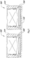
- Figure 1 illustrated a conventional dual-lens camera module, which includes a circuit board 10P, two stands 20P, and two imaging modules 30P.
- Each imaging module 30P includes a motor lens assembly 31P.
- Each stand 20P is independently provided on the same side of the circuit board 10P.
- the stands 20P are connected by the circuit board 10P.
- Each lens assembly 31P is respectively arranged on the respective stand 20P so as to be supported thereby.
- each stand 20P is independently attached on the circuit board 10P, which causes difficulties of controlling the dimensions, positions, and etc. between the stands 20P. As a result, the consistencies of the parameters of the dimensions, positions, and etc. between the stands 20P are relatively poor.
- every stand 20P is independent and the stands 20P are connected only by the circuit board 10P.
- the circuit board 10P is usually chosen to be a PCB circuit board, it is soft and easy to be deformed. Consequently, the overall rigidity of the dual-lens camera module can hardly be guaranteed.
- the conventional dual-lens camera module is produced and utilized, such conventional structure can cause uncertain and inconsistent dimensions and large positional tolerance among all the elements of the imaging modules 30P, such as the lens assemblies 31P and etc.
- the optic axes of the imaging modules 30P can easily deviate from the designated positions.
- the stands 20P are positioned through the way of attaching reinforcing element on a side of the circuit board 10P, it will increase the thickness of the dual-lens camera module, which should not be an ideal solution.
- the imaging modules 30P when the dual-lens camera module is in use, the imaging modules 30P will produce plenty of heat. The accumulation of heat can heat up the circuit board 10P and cause deformation. If the circuit board 10P deforms, the assembling positions of the stands 20P that are independently attached on the circuit board 10P will be forced to change relatively. Consequently, the positions of the imaging modules 30P supported by the stands 20P will also be changed at the same time, which brings incalculable consequence to the conventional dual-lens camera module.
- US20150201128A1 discloses a lens array device, which includes a base for retraining a plurality of image sensors and a holder for retaining the lenses, wherein the holder can be driven to move in a direction orthogonal to the optical axis direction.
- CN105187697A and CN204993579U of the applicant relate to a comparable multi-lens camera module and its multi-lens camera module conjoined stand, in which CN105187697A (with the Chinese application number " 201510472665.7 ”) was claimed as a priority of the present European application.
- CN204948203U , CN104834158A and CN204633900U relate to a dual-lens camera module comprising two lens units, respectively.
- CN102573277A is to be mentioned as a relevant prior art, which discloses a 3-D image pick-up device, including: a PCB mounted with two camera modules including an image sensor; and a reinforcing member provided with two exposure windows, wherein the PCB and the reinforcing member are mutually adhered to allow the camera modules to be exposed through the exposure windows of the reinforcing member.
- the photographic module comprises a lens module and a sensing module.
- the adjustable support comprises a support main body and an adjusting unit.
- the support main body is provided with a channel.
- the adjusting unit is arranged on the support main body.
- the lens module and the sensing module are connected through the adjustable support, and are communicated with each other through the channel
- US2013141541 discloses a lens assembly array for four cameras. All four lens assemblies are attached to one holder and are driven by one common actuator i.e. all cameras move together for focusing.
- CN203933331 discloses a triple camera system, each camera is individually driven through voice coil motors and are attached to one singly printed circuit board which is also the base for all three cameras as well.
- CN203416328U relates to an array type camera module group, which comprises multiple camera module group bodies and a coplanar member.
- the multiple camera module group bodies are arranged at the same optical plane in an array, and the coplanar member enables that the multiple camera module group bodies are positioned in the same plane.
- CN202652361U discloses a dual camera module, which comprises a first camera, a second camera, a pedestal, and a connector. Two camera installing grooves are provided on the pedestal. The first camera is provided in one camera installing groove in the pedestal, and the second camera is provided in the other camera installing groove in the pedestal. The first camera and the second camera are respectively connected to different pins of the connector.
- the present invention provides a multi-lens camera module according to claim 1.
- An object of the present invention is to provide a multi-lens camera module and its multi-lens module conjoined stand, and the application thereof, wherein the multi-lens camera module comprises an integrated multi-lens camera module conjoined stand, at least two lens assemblies, and at least two photosensitive assemblies, wherein the multi-lens camera module conjoined stand supports the lens assemblies and the photosensitive assemblies, wherein the integrated multi-lens camera module conjoined stand can avoid tilt relatively between the paths of photoreception of the lens assemblies, so as to ensure the consistency of the multi-lens camera module.
- Another object of the present invention is to provide a multi-lens camera module and its multi-lens camera module conjoined stand, and the application thereof, wherein the integrated multi-lens camera module conjoined stand does not require to connect independent stands together, such that the multi-lens camera module conjoined stand can avoid positional tolerance from occurring between the adjacent lens assemblies, which can help to enhance the imaging quality of the multi-lens camera module.
- Another object of the present invention is to provide a multi-lens camera module conjoined stand, multi-lens camera module and application thereof, wherein the integrated multi-lens camera module conjoined stand does not require to be connect by other element, such as circuit board and etc., such that when the multi-lens camera module conjoined stand is utilized to assemble the multi-lens camera module and during the transportation and application of the multi-lens camera module, the multi-lens camera module conjoined stand will not be deformed accordingly so as to ensure t the imaging quality of the multi-lens camera module.
- Another object of the present invention is to provide a multi-lens camera module and its multi-lens camera module conjoined stand, and the application thereof, wherein the photosensitive assembly provide a circuit board that does not have to be utilized for connecting independent stands, such that the circuit board is capable of being integrated in a photosensitive sensor or being made with a thinner size.
- the circuit board can be a FPC circuit board. Accordingly, it can reduce the thickness of the multi-lens camera module and then allow the multi-lens camera module to be utilized in more compact mobile electronics.
- Another object of the present invention is to provide a multi-lens camera module conjoined stand, multi-lens camera module and application thereof, wherein the integrated multi-lens camera module conjoined stand does not require to connect two or more independent stands together during the assembling process of the multi-lens camera module, that simplifies the assembling steps of the multi-lens camera module and increases the assembling efficiency of the multi-lens camera module.
- Another object of the present invention is to provide a multi-lens camera module conjoined stand, multi-lens camera module and application thereof, wherein the multi-lens camera module conjoined stand comprises a connecting body and two stand bodies, wherein the stand bodies are integrally extended from two sides of the connecting body respectively while each of the stand bodies is adapted for being connected with one of the lens assemblies and one of the photosensitive assemblies, wherein the multi-lens camera module conjoined stand can ensure the central axis lines of the stand bodies being parallel to each other, so as to avoid tilt from occurring between the paths of photoreception of adjacent lens assemblies.
- Another object of the present invention is to provide a multi-lens camera module conjoined stand, multi-lens camera module and application thereof, wherein the multi-lens camera module conjoined stand prevents the photosensitive sensors of the photosensitive assemblies from being in the same packaging space with other electronic components during the assembling process of the multi-lens camera module, so as to avoid the photosensitive sides of the photosensitive sensors from being polluted by welding slag, dust, and etc. dropped from the surfaces of the electronic components, that helps to avoid defective pixel from occurring on the photosensitive sides of the photosensitive sensors.
- the present invention provides a multi-lens camera module, comprising
- the multi-lens camera module conjoined stand comprises at least one connecting body and at least two stand bodies, wherein each of the stand bodies is extended from one of the at least one connecting body, wherein the stand bodies support the lens assemblies and the photosensitive assemblies respectively.
- the multi-lens camera module conjoined stand comprises one connecting body and two stand bodies, wherein the stand bodies are symmetrically and integrally extended from the connecting body.
- a least one of the stand bodies has a light channel, a first packaging groove and a second packaging groove respectively communicated with the light channel, wherein the lens assembly is corresponding to the first packaging groove and connected with the upside of the multi-lens camera module conjoined stand, wherein the photosensitive assembly is corresponding to the second packaging groove and connected with the downside of the multi-lens camera module conjoined stand.
- the multi-lens camera module conjoined stand has at least two light channels, at least two first packaging grooves and at least two second packaging grooves, wherein each of the first packaging grooves and each of the second packaging grooves are respectively communicated with one of the at least two light channels, wherein the lens assembly is corresponding to the first packaging groove and connected with the upside of the multi-lens camera module conjoined stand, wherein the photosensitive assembly is corresponding to the second packaging groove and connected with the downside of the multi-lens camera module conjoined stand.
- At least one of the connecting bodies comprises a connecting portion and an attaching portion, wherein the attaching portion is extended from the stand body and the connecting portion is extended from the inner side of the attaching portion, wherein the thickness dimension of the connecting portion is smaller than the thickness dimension of the attaching portion, so as to respectively form the first packaging groove and the second packaging groove on the two side portions of the connecting portion along the thickness direction of the multi-lens camera module.
- At least one of the stand bodies comprises a loading portion extended from the inner side of the connecting portion, wherein the loading portion defines the light channel, wherein the thickness dimension of the loading portion is smaller than the thickness dimension of the connecting portion, so as to form a stair on the side of the connecting portion along the thickness direction of the multi-lens camera module.
- the multi-lens camera module further comprises at least two filtering elements arranged on the stairs formed by the loading portions respectively.
- the stair and the first packaging groove are on the same side of the multi-lens camera module conjoined stand.
- the stair and the second packaging groove are on the same side of the multi-lens camera module conjoined stand.
- the at least one connecting body comprises an electronic component accommodating cavity arranged thereon, wherein the electronic component accommodating cavity is impassable to the first packaging groove, the second packaging groove and the light channel, wherein each the photosensitive assembly comprises a circuit board and a sensor electrically connected with the circuit board, wherein the circuit board comprises an electronic component and is adaptable for being attached on the downside of one the multi-lens camera module conjoined stand, wherein the photosensitive sensor is packaged and sealed in the second packaging groove and the electronic component is packaged and sealed in the electronic component accommodating cavity.
- the electronic component accommodating cavity and the second packaging groove are on the same side of the multi-lens camera module conjoined stand.
- the circuit board is a PCB circuit board or a FPC circuit board.
- the alignment of the central axes of the stand bodies is parallel or vertical to the peripheral of the multi-lens camera module conjoined stand.
- the range of the distance between the central axes of the stand bodies is 5mm-200mm.
- the range of the distance between the central axes of the stand bodies is 9mm.
- the material of the multi-lens camera module conjoined stand is selected from the group consisting of thermoplastic resin, engineering plastics, metal, and alloy.
- the material of the multi-lens camera module conjoined stand is aluminum alloy or zinc alloy.
- the material of the multi-lens camera module conjoined stand is metal powder or mixture of metal powder and nonmetal powder.
- the present invention also provides a multi-lens camera module conjoined stand for connecting with at least two lens assemblies and at least two photosensitive assemblies, wherein the multi-lens camera module conjoined stand is integrally formed.
- each of the stand bodies comprises an attaching portion, a connecting portion and a loading portion, wherein the attaching portion is extended from the connecting body and the connecting portion is connected with the attaching portion and the loading portion, wherein the loading portion comprises a light channel arranged therein.
- the thickness dimension of the loading portion is smaller than the thickness dimension of the connecting portion so as to form a stair on the side of the connecting portion along the thickness direction of the multi-lens camera module conjoined stand.
- the thickness dimension of the connecting portion is smaller than the thickness dimension of the attaching portion so as to form a first packaging groove and a second packaging groove on the two side portions of the connecting portion respectively along the thickness direction of the multi-lens camera module conjoined stand, wherein the first packaging groove and the second packaging groove are respectively communicated with the light channel.
- the present invention also provides a method for avoiding two or more lens assemblies and two or more photosensitive assemblies of a multi-lens camera module from deviation, wherein the method comprises the following steps:
- the multi-lens camera module conjoined stand comprises at least one connecting body and at least two stand bodies, wherein each the stand body is extended from at least one of the connecting body, wherein the stand bodies support the lens assemblies and the photosensitive assemblies respectively.
- the multi-lens camera module conjoined stand comprises one connecting body and two stand bodies, wherein the stand bodies are symmetrically and integrally extended from the connecting body.
- a multi-lens camera module according to a preferred embodiment of the present invention is illustrated, wherein the multi-lens camera module can be utilized in various electronic devices, so as to assist the user to shoot image of objects or persons through the multi-lens camera module.
- the multi-lens camera module can be utilized to shoot imaging information, such as picture or video of objects, persons, and etc..
- the multi-lens camera module can be utilized in a mobile electronic device, which can be, for example but not limited to, a mobile phone or tablet.
- the multi-lens camera module of the present invention is embodied as a dual-lens camera module in the following description to give examples for illustrating contents and advantages of the present invention.
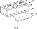
- the dual-lens camera module can comprise a multi-lens camera module conjoined stand 10, at least two lens assemblies 20, and at least two photosensitive assemblies 30.
- the lens assemblies 20 and the photosensitive assemblies 30 are connected to different sides of the multi-lens camera module conjoined stand 10 respectively.
- Each of the lens assemblies 20 is positioned corresponding to a path of photoreception of one of the photosensitive assemblies 30 so as to be arranged in a one-on-one manner.
- the photosensitive assemblies 30 can be coupled with the electronic device.
- one of the lens assemblies 20 paired with one of the photosensitive assemblies 30 can coordinate for capturing image. Specifically, light reflected from objects or persons and passed through the lens assemblies 20 will respectively be received by the photosensitive assemblies 30 for photoelectric conversion. That is to say, the photosensitive assemblies 30 can convert light signals into electrical signals and the electrical signals can be sent to the electronic device through the photosensitive assemblies 30, so as for the electronic device to generate relative image of the objects or persons therefor.
- the multi-lens camera module conjoined stand 10 has an upside 101 and a downside 102.
- the upside 101 and the downside 102 of the multi-lens camera module conjoined stand 10 are opposite to each other.
- Each lens assembly 20 is connected with the upside 101 of the multi-lens camera module conjoined stand 10.
- Each photosensitive assembly 30 is connected with the downside 102 of the multi-lens camera module conjoined stand 10. It is worth mentioning that, referring to Fig. 4 , the side of the dual-lens camera module that is closer to the objects or persons being shot is defined as the upside 101 of the multi-lens camera module conjoined stand 10.
- the side of the dual-lens camera module that is away from the objects or persons being shot is defined as the downside 102 of the multi-lens camera module conjoined stand 10. Therefore, it is understandable that when the dual-lens camera module is utilized in a mobile electronic device, such as mobile phone, digital camera and etc., and held on the user's hand, the upside 101 and the downside 102 of the multi-lens camera module conjoined stand 10 may have a front and back relationship rather than an up and down relationship in terms of spatial position.
- the multi-lens camera module conjoined stand 10 comprises a connecting body 11 and two stand bodies 12, wherein the stand bodies 12 are integrally extended from the connecting body 11, wherein each of the stand bodies 12 is utilized to support one of the lens assemblies 20 and one of the photosensitive assemblies 30.
- the connecting body 11 of the multi-lens camera module conjoined stand 10 and the stand bodies 12 are integrally formed, such that the multi-lens camera module conjoined stand 10 provided by the present invention is an integral body that can overcome the technical defects in the prior art, such as positional deviations and angle deviations between two independent stands, wherein the two separating stands are connected together by means of another element such as the circuit board.
- the multi-lens camera module conjoined stand 10 can avoid relative tilt between the paths of photoreception of the lens assemblies 20 and the photosensitive assemblies 30, so as to guarantee the consistency and imaging quality of the dual-lens camera module.
- each of the lens assemblies 20 can comprise an optical lens 21 directly connected on one of the stand bodies 12 of the multi-lens camera module conjoined stand 10.
- the lens assembly 20 is a fixed focus lens assembly, which means the focal length of the lens assembly 20 cannot be freely adjusted.
- the optical lens 21 illustrated in the present invention can be directly connected with the stand body 12, which includes connecting the optical lens 21 with the stand body 12 through a shell.
- each of the lens assemblies 20 can also comprise a driving motor 22 connected with the stand body 12 of the multi-lens camera module conjoined stand 10.
- Each optical lens 21 is drivably connected with the driving motor 22, such that the driving motor 22 can drive the optical lens 21 to move along the path of photoreception of the photosensitive assembly 30, so as to adjust the focal length of the lens assembly 20.
- the lens assemblies 20 are zoom lens assemblies, which mean the focal lengths of the lens assemblies 20 are adjustable. For instance, if a user is utilizing the dual-lens camera module to shoot image, he may adjust the shooting result through adjusting the focal lengths of the lens assemblies 20.
- each of the photosensitive assemblies 30 can comprise a photosensitive sensor 31.
- the photosensitive side of the photosensitive sensor 31 is facing the optical lens 21 of the lens assembly 20 and an optic axis of the optical lens 21 is perpendicular to the photosensitive side of the photosensitive sensor 31, such that after the light passes through the optical lens 21, the light can be received by the photosensitive side of the photosensitive sensor 31 for subsequent photoelectric conversion.
- the circuit of each photosensitive assembly 30 can be arranged on the photosensitive sensor 31 and each photosensitive assembly 30 is coupled with the electronic device through the circuit.
- the photosensitive assembly 30 may also comprise a circuit board 32, wherein each photosensitive sensor 31 can be electrically connected with the circuit board 32.
- the circuit board 32 is coupled with the electronic device, such that the circuit board 32 can be utilized to send the electrical signal generated by the photosensitive sensor 31 through photoelectric conversion to the electronic device.
- the photosensitive sensor 31 can be electrically connected to the circuit board 32 by being attached on different positions of the circuit board 32.
- the circuit board 32 is connected on the multi-lens camera module conjoined stand 10 and the photosensitive sensors 31 are corresponded to the stand bodies 12 respectively.
- the photosensitive sensor 31 was attached on the circuit board 32, it can be electrically connected with the circuit board 32 through at least a wire bond.
- the dual-lens camera module provides at least a wire bond. The two ends of the wire bond are respectively extended to connect with the fringe of the photosensitive sensor 31 and the circuit board 32, so as to achieve the electrical connection between the photosensitive sensor 31 and the circuit board 32.
- the wire bond should not be the only feasible implementation for electrically connecting the photosensitive sensor 31 and the circuit board 32.
- the photosensitive sensor 31 and the circuit board 32 can also be welded and solder the solder balls. It is worth mentioning that, according to the dual-lens camera module of the present invention, the connection mode of the sensor 31 and the circuit board 32 shall not limit the content and scope of the present invention.
- the lens assemblies 20 of the dual-lens camera module can both be zoom lens assemblies.
- the distances between the optical lenses 21 of the lens assemblies 20 and the sensors 31 of the photosensitive assemblies 30 can be adjusted.
- each of the optical lenses 21 can be driven by the corresponding driving motor 22 so as to move along the path of photoreception of the corresponding photosensitive sensor 31, such that the focal length of the dual-lens camera module can be adjusted through the shift between the optical lens 21 and the photosensitive side of the photosensitive sensor 31.
- the relative positions of the lens assemblies 20 and the photosensitive assemblies 30 can be synchronously adjusted. Nonetheless, according to another preferred implementation of the present invention, the relative positions of the lens assemblies 20 and the photosensitive assemblies 30 can respectively be independently adjusted.
- the stand bodies 12 of the multi-lens camera module conjoined stand 10 are integrally extended from two side portions of the connecting body 11 respectively.
- Each stand body 12 is utilized to connect one of the lens assemblies 20 and one of the photosensitive assemblies 30, so as to form the dual-lens camera module.
- the specification of the stand bodies 12 may not be limited. For instance, in one embodiment, the sizes of the stand bodies 12 can be different. For another preferred implementation of the present invention, the specifications of the stand bodies 12, including the dimensions, are all the same, which means the stand bodies 12 can be symmetrically extended to both sides of the connecting body 11.
- each stand body 12 has a light channel 121 to communicate the upside 101 and the downside 102 of the multi-lens camera module conjoined stand 10.
- Each lens assembly 20 and each photosensitive assembly 30 of the dual-lens camera module can interact through the respective light channel 121 of each of the stand bodies 12.
- the light channel 121 is arranged in the central position of each of the stand bodies 12.
- Each stand body 12 can further comprise a loading portion 122, a connecting portion 123 and an attaching portion 124, which are integrated or integrally formed.
- the light channel 121 is arranged in the loading portion 122. It is understandable that the loading portion 122 is at the inner side of the stand body 12, the attaching portion 124 is at the outer side of the stand body 12, and the connecting portion 123 is for connecting the loading portion 122 and the attaching portion 124. In other words, the loading portion 122, the connecting portion 123 and the attaching portion 124 are arranged on the stand body 12 along an internal to external manner.
- a thickness dimension of the loading portion 122 is smaller than the thickness dimension of the connecting portion 123 along the direction of the path of photoreception of the respective photosensitive sensor 31, such that the stand body 12 can form a stair 1221 at the place corresponding to the loading portion 122.
- the dual-lens camera module also comprises at least two filtering elements 40 arranged on the stairs 1221 formed by the loading portions 122 to be supported by the loading portions 122 respectively. It is worth mentioning that the position of the stair 1221 formed by the loading portion 122 can be limited. For example, the stair 1221 formed by the loading portion 122 may be arranged on either the upside 101 of the multi-lens camera module conjoined stand 10 or the downside 102 of the multi-lens camera module conjoined stand 10.
- the thickness dimension of the connecting portion 123 is also smaller than the thickness dimension of the attaching portion 124 along the direction of the path of photoreception of the photosensitive sensor 31, so as to respectively form a first packaging groove 125 and a second packaging groove 126 of the stand body 12 at a position corresponding to the connecting portion 123.
- the first packaging groove 125 is on the upside 101 of the multi-lens camera module conjoined stand 10, while the second packaging groove 126 is on the downside 102 of the multi-lens camera module conjoined stand 10.
- the first packaging groove 125 and the second packaging groove 126 are respectively communicated with the light channel 121.
- the lens assembly 20 can be corresponding to the first packaging groove 125 of the stand body 12 and sealed and packaged on the multi-lens camera module conjoined stand 10.
- the photosensitive assembly 30 can be corresponding to the second packaging groove 126 of the stand body 12 and sealed and packaged on the multi-lens camera module conjoined stand 10.
- a side of the lens assembly 20 can be sealed and packaged on the stand body 12 corresponding to the first packaging groove 125.
- the side of the lens assembly 20 may comprise a guide pin arranged on the side and extended into the first packaging groove 125, so as to implement the sealing and packaging of the lens assembly 20 and the stand body 10.
- the circuit board 32 of the photosensitive assembly 30 can be attached on the attaching portion 124 of the stand body 12, so as to seal and package the photosensitive sensor 31 of the circuit board 32 in the second packaging groove 126 of the stand body 12 and to arrange the optic axis of the optical lens 21 of the lens assembly 20 being perpendicular to the photosensitive side of the photosensitive sensor 31 of the photosensitive assembly 30.
- the periphery of the sensor 31 of the photosensitive assembly 30 can be extended for being sealed and packaged on the attaching portion 124 directly.
- the photosensitive sensor 31 is positioned in the second packaging groove 126.
- the multi-lens camera module conjoined stand 10 is an integral body. Contrasting to the prior art that two or more independent stands are connected to form a stand of the dual-lens camera module, the integral multi-lens camera module conjoined stand 10 of the present invention provides the following outstanding advantages.
- a first advantage of the multi-lens camera module conjoined stand 10 is that the multi-lens camera module conjoined stand 10 can overcome the technical defects of the independent stands of conventional dual-lens camera module, such as positional deviations and angle deviations between the independent stands when connecting the separate stands and etc., so as to avoid relative tilt between the paths of photoreception of the lens assemblies 20 and the photosensitive assemblies 30 after sealing and packaging.
- a second advantage of the multi-lens camera module conjoined stand 10 is that when the dual-lens camera module of the present invention experiences severely shaken and vibration, the stand bodies 12 integrally extended from the connecting body 11 can retain and ensure the relative positions of the lens assemblies 20 and the photosensitive assemblies 30, such as the tilt, distance, and etc., among the lens assemblies 20 and the photosensitive assemblies 30.
- a third advantage of the multi-lens camera module conjoined stand 10 is the thinner thickness thereof.
- the independent stands of the conventional art are connected by means of the circuit board. Therefore, in order to ensure the stability of the relative positions of the stands, a circuit board with certain thickness and rigidity is required for conventional multi-lens camera module.
- the conventional dual-lens camera module can only utilize a PCB type circuit board that undoubtedly increases the thickness thereof.
- the circuit board 32 of the dual-lens camera module of the present invention does not need to have to connect the stands. Therefore, there is no necessary requirement to the thickness and hardness of the circuit board 32.
- the circuit board 32 can be a PCB type circuit board or a FPC circuit board with even thinner thickness.
- the dual-lens camera module may even do not include the circuit board 32, but simply integrate the circuit into the photosensitive sensors 31, so as to greatly reduce the thickness of the dual-lens camera module in the direction of the path of photoreception of the photosensitive sensors 31, which allows the dual-lens camera module to be utilized on the electronic devices expected to be lighter and thinner.
- the conventional independent stands can only be connected through the circuit board, so a space has to be reserved between adjacent stands for accommodating the electronic components attached on the circuit board.
- the circuit board could be heated and deformed easily. Once the circuit board is deformed, the slopes of the independent stands will inevitably be changed, which will consequently impact the imaging quality of the conventional dual-lens camera module.
- the connecting body 11 of the multi-lens camera module conjoined stand 10 further has an electronic component accommodating cavity 111 provided therein for accommodating and receiving one or more electronic components 321 attached on the circuit board 32.
- the electronic component accommodating cavity 111 of the connecting body 11 is impassable to the light channel 121, the first packaging groove 125 and the second packaging groove 126 of the stand body 12.
- the electronic component 321 is adapted to be sealed and packaged within the electronic component accommodating cavity 111 of the connecting body 11 alone, such that the pollutants, such as welding slags, dusts, and etc., will not enter the second packaging groove 126 of the stand body 12 to pollute the photosensitive side of the photosensitive sensor 31 of the photosensitive assembly 30 sealed and packaged in the second packaging groove 126 of the stand body 12, that avoids defective pixel from occurring on the photosensitive side of the sensor 31 so as to further increase the imaging quality of the dual-lens camera module.
- the electronic component accommodating cavity 111 of the connecting body 11 is formed in a gap adjacent to the stand bodies 12, which not only utilizes spare space of the dual-lens camera module, but also avoids being deformed easily due to the fact that the electronic component accommodating cavity 111 of the connecting body 11 prevents the stress of the multi-lens camera module conjoined stand 10 from concentrating because of the position of the connecting body 11 , such that a stability of the multi-lens camera module conjoined stand in use is ensured.
- each of the stand bodies 12 of the multi-lens camera module conjoined stand 10 has a central axis and the distance between the central axes of the stand bodies 12 can be ranged 5mm to 200mm.
- the distance between the central axes of the stand bodies 12 can be 9mm.
- the alignment between the central axes of the stand bodies 12 is parallel or perpendicular to each fringe of the multi-lens camera module conjoined stand 10, so that when the dual-lens camera module assembled with the multi-lens camera module conjoined stand 10, the lens assemblies 20 and the photosensitive assemblies 30 is installed in the electronic device, the path of photoreception of each of the lens assemblies 20 and each of the photosensitive assemblies 30 can be controlled more easily.
- the conventional dual-lens camera module needs to affix two independent stands on the circuit board but, based on its assembling process, the distance between the central axes of the two independent stands of the conventional dual-lens camera module is very difficult to be controlled, which renders a poor consistency of the dual-lens camera module according to conventional art.
- the two independent stands of the conventional dual-lens camera module are only affixed by the circuit board. In other words, the conventional dual-lens camera module depends on the circuit board for symmetrically securing two independent stands on the circuit board.
- the circuit board of the conventional dual-lens camera module is PCB in practical application, which is insufficient to support two or more independent stands, two or more lens assemblies, and two or more photosensitive assemblies. Also, PCB type circuit board can easily be deformed under heat. Besides, more and more lens assemblies and photosensitive assemblies are demanded in the multi-lens camera module, whereas the structure of conventional stand is more inadequate in making a multi-lens camera module that has more than two stands, two lens assemblies, and two photosensitive assemblies.
- the multi-lens camera module conjoined stand 10 can be integrally formed by thermoplastic resin material that reinforces the stability of the multi-lens camera module conjoined stand 10.
- the multi-lens camera module conjoined stand 10 may also be integrally formed by engineering plastics, wherein the material formed by engineering plastics particles can be poured into the mold to produce the multi-lens camera module conjoined stand 10.
- the material of the multi-lens camera module conjoined stand 10 may be "ishiNTB982" engineering plastics, Liquid Crystal Polymer (LCP) engineering plastics, or etc.
- the multi-lens camera module conjoined stand 10 can also be made of metallic material or alloy material, so as to not only guarantee the intensity of the multi-lens camera module conjoined stand 10, but also enhance the heat dissipation of the multi-lens camera module conjoined stand 10.
- the multi-lens camera module conjoined stand 10 can be integrally formed by metal powder or mixture of metal powder and nonmetal powder through injection molding technology or 3D printing technology.
- the material of the multi-lens camera module conjoined stand 10 can be aluminum alloy, zinc alloy, or etc.
- the multi-lens camera module conjoined stand 10 of the present invention provides a new thought of heat dissipation for the dual-lens camera module. That is, the present invention utilizes the multi-lens camera module conjoined stand 20 arranged on the circumferential of the photosensitive sensors 31 of the photosensitive assemblies 30 to implement heat dissipation. Firstly, the multi-lens camera module conjoined stand 10 has a bigger radiating surface that can increase the heat dissipation performance of the dual-lens camera module.
- the circuit board 32 is not likely to be deformed due to high temperature and there is no need to attach radiating fin on the outer side of the circuit board 32 as a heat dissipation aid, such that the thickness of the dual-lens camera module in the direction of the path of photoreception can further be reduced, which makes the dual-lens camera module especially suitable for the electronic devices expected to be lighter and thinner.
- Fig. 6 is a comparison diagram of the rigid strength simulation of a conventional dual-lens camera module and the dual-lens camera module according to the present invention under stress.
- the multi-lens camera module conjoined stand 10 of the dual-lens camera module of the present invention utilizes an integral structure, which significantly strengthens the rigidity thereof.
- the degree of distortion will gradually be greater for the position more to the right side of the independent stands and less for the position more to the left side of the independent stands.
- the test results indicate that the required external force to apply on the conventional dual-lens camera module for changing the angle of its optic axis for 0.5° is 1.17N, while the required external force to apply on the dual-lens camera module of the present invention for changing the angle of its optic axis for 0.5° is 11.8N.
- the test results have revealed that the overall rigidity of the dual-lens camera module of the present invention is far greater than the overall rigidity of the conventional dual-lens camera module, which means the dual-lens camera module of the present invention is more stable.
- the multi-lens camera module being embodied as the dual-lens camera module in the above description of the present invention is just an example for describing and illustrating the content and scope of the present invention.
- the multi-lens camera module conjoined stand 10 may also provide three or more stand bodies 12, so as to implement the multi-lens camera module beyond the dual-lens camera module, where the multi-lens camera module, for example, may be embodied as a tri-lens camera module, tetra-lens camera module, and etc..
- the multi-lens camera module of the present invention has significant non-obviousness.
- the multi-lens camera module can comprise one integrated multi-lens camera module conjoined stand 10, six the lens assemblies 20 and six the photosensitive assemblies 30, wherein the multi-lens camera module conjoined stand 10 provides six stand bodies 12, where each one of the stand bodies 12 is utilized to support one of the lens assemblies 20 and one of the photosensitive assemblies 30 so as to form the multi-lens camera module. It is worth mentioning that the correspondingly aligned lens assemblies 20 and photosensitive assemblies 30 are arranged into an array manner, where the multi-lens camera module forming an array camera module.
- the present invention also provides a method for avoiding the lens assemblies 20 and the photosensitive assemblies 30 of the multi-lens camera module from deviation, wherein the method comprises the following steps:
Description
- A portion of the disclosure of this patent document contains material which is subject to copyright protection. The copyright owner has no objection to any reproduction by anyone of the patent disclosure, as it appears in the United States Patent and Trademark Office patent files or records, but otherwise reserves all copyright rights whatsoever.
- The present invention relates to a multi-lens optical imaging device, and more particularly to a multi-lens camera module and its multi-lens camera module conjoined stand and the application thereof.
- Nowadays, electronic products mostly tend to integrate more functions. This trend stimulates the creation of multifunctional products. For example, cellphone has evolved from the original communication device into a highly integrated mobile electronic device with diverse and multidimensional functions, such as communication, photography, internet, navigation, and etc.
- In recent years, along with the invention and popularization of social networking APPs, such as WeChat, Whatsapp and etc., of mobile electronic devices, a new communication pattern among people has emerged. For example, WeChat provides a Group of Friends function that allows the user to publish images like pictures, videos, and etc. taken by the camera module that is arranged on the mobile electronic device, so that the user's friends may comment or like the posted content. This type of behavior has changed the communication pattern among people to a great extent and boosted information transmission and exchange among people. Nevertheless, the camera modules arranged on mobile electronic devices are mostly single lens camera modules currently, which can no longer satisfy user's demand on image quality and effect of the image shot by mobile electronic devices.
- On the other hand, camera modules with two or more lenses, such as dual-lens camera module, has been created and become more and more popular. Dual-lens camera module provides shooting means that imitates the structure of human eyes. Besides, it has more excellent performance on various approaches, such as 3D photography shooting and scanning, hand sign and motion recognition, color naturalness, fast focusing, deep panorama photography, bokeh photography, and etc.. Therefore, camera module with two or more lenses should be a critical trend of development for camera module industry. During the image shooting process, the dual-lens camera module utilizes two image modules that are spatially different to respectively obtain an image from two positions and composites with the images shot by these two image modules through an image composition method, so as to obtain a final image of the multi-lens camera module. It is understandable that the consistency of the image effects, including resolution, shading, color, and etc., of each image module of the multi-lens camera module and the deviations in the horizontal, vertical, and longitudinal directions thereof are important indicators to measure the imaging quality of the dual-lens camera module.
- Unfortunately, both the manufacturing and assembling technology and the final structure of the dual-lens camera module are far from ensuring the imaging quality of the dual-lens camera module currently.
Figure 1 illustrated a conventional dual-lens camera module, which includes acircuit board 10P, twostands 20P, and twoimaging modules 30P. Eachimaging module 30P includes amotor lens assembly 31P. Eachstand 20P is independently provided on the same side of thecircuit board 10P. Thestands 20P are connected by thecircuit board 10P. Eachlens assembly 31P is respectively arranged on therespective stand 20P so as to be supported thereby. It is understandable that based on the assembly technology of the conventional dual-lens camera module, eachstand 20P is independently attached on thecircuit board 10P, which causes difficulties of controlling the dimensions, positions, and etc. between thestands 20P. As a result, the consistencies of the parameters of the dimensions, positions, and etc. between thestands 20P are relatively poor. - Based on the structure of the conventional dual-lens camera module, every
stand 20P is independent and thestands 20P are connected only by thecircuit board 10P. Because thecircuit board 10P is usually chosen to be a PCB circuit board, it is soft and easy to be deformed. Consequently, the overall rigidity of the dual-lens camera module can hardly be guaranteed. When the conventional dual-lens camera module is produced and utilized, such conventional structure can cause uncertain and inconsistent dimensions and large positional tolerance among all the elements of theimaging modules 30P, such as the lens assemblies 31P and etc. Moreover, the optic axes of theimaging modules 30P can easily deviate from the designated positions. Once any of the above has occurred, there will be uncontrollable factors or relatively big adverse impact to the imaging quality, such as the final imaging result of the image synthesis and etc., of the conventional dual-lens camera module. If thestands 20P are positioned through the way of attaching reinforcing element on a side of thecircuit board 10P, it will increase the thickness of the dual-lens camera module, which should not be an ideal solution. - Besides, when the dual-lens camera module is in use, the
imaging modules 30P will produce plenty of heat. The accumulation of heat can heat up thecircuit board 10P and cause deformation. If thecircuit board 10P deforms, the assembling positions of thestands 20P that are independently attached on thecircuit board 10P will be forced to change relatively. Consequently, the positions of theimaging modules 30P supported by thestands 20P will also be changed at the same time, which brings incalculable consequence to the conventional dual-lens camera module. -
US20150201128A1 discloses a lens array device, which includes a base for retraining a plurality of image sensors and a holder for retaining the lenses, wherein the holder can be driven to move in a direction orthogonal to the optical axis direction. -
CN105187697A andCN204993579U of the applicant, as Chinese applications filed on the same date concerning the same subject matter, relate to a comparable multi-lens camera module and its multi-lens camera module conjoined stand, in whichCN105187697A (with the Chinese application number "201510472665.7 -
CN204948203U ,CN104834158A andCN204633900U , which are not previously published, relate to a dual-lens camera module comprising two lens units, respectively.CN102573277A is to be mentioned as a relevant prior art, which discloses a 3-D image pick-up device, including: a PCB mounted with two camera modules including an image sensor; and a reinforcing member provided with two exposure windows, wherein the PCB and the reinforcing member are mutually adhered to allow the camera modules to be exposed through the exposure windows of the reinforcing member. -
CN204422842U , owned by the applicant, discloses a photographic module and an adjustable motor support thereof. The photographic module comprises a lens module and a sensing module. The adjustable support comprises a support main body and an adjusting unit. The support main body is provided with a channel. The adjusting unit is arranged on the support main body. The lens module and the sensing module are connected through the adjustable support, and are communicated with each other through the channel -
US2013141541 discloses a lens assembly array for four cameras. All four lens assemblies are attached to one holder and are driven by one common actuator i.e. all cameras move together for focusing. -
CN203933331 discloses a triple camera system, each camera is individually driven through voice coil motors and are attached to one singly printed circuit board which is also the base for all three cameras as well. -
CN203416328U relates to an array type camera module group, which comprises multiple camera module group bodies and a coplanar member. The multiple camera module group bodies are arranged at the same optical plane in an array, and the coplanar member enables that the multiple camera module group bodies are positioned in the same plane. -
CN202652361U discloses a dual camera module, which comprises a first camera, a second camera, a pedestal, and a connector. Two camera installing grooves are provided on the pedestal. The first camera is provided in one camera installing groove in the pedestal, and the second camera is provided in the other camera installing groove in the pedestal. The first camera and the second camera are respectively connected to different pins of the connector. - In order to obviate at least some of the shortcomings of the prior arts, the present invention provides a multi-lens camera module according to claim 1.
- An object of the present invention is to provide a multi-lens camera module and its multi-lens module conjoined stand, and the application thereof, wherein the multi-lens camera module comprises an integrated multi-lens camera module conjoined stand, at least two lens assemblies, and at least two photosensitive assemblies, wherein the multi-lens camera module conjoined stand supports the lens assemblies and the photosensitive assemblies, wherein the integrated multi-lens camera module conjoined stand can avoid tilt relatively between the paths of photoreception of the lens assemblies, so as to ensure the consistency of the multi-lens camera module.
- Another object of the present invention is to provide a multi-lens camera module and its multi-lens camera module conjoined stand, and the application thereof, wherein the integrated multi-lens camera module conjoined stand does not require to connect independent stands together, such that the multi-lens camera module conjoined stand can avoid positional tolerance from occurring between the adjacent lens assemblies, which can help to enhance the imaging quality of the multi-lens camera module.
- Another object of the present invention is to provide a multi-lens camera module conjoined stand, multi-lens camera module and application thereof, wherein the integrated multi-lens camera module conjoined stand does not require to be connect by other element, such as circuit board and etc., such that when the multi-lens camera module conjoined stand is utilized to assemble the multi-lens camera module and during the transportation and application of the multi-lens camera module, the multi-lens camera module conjoined stand will not be deformed accordingly so as to ensure t the imaging quality of the multi-lens camera module.
- Another object of the present invention is to provide a multi-lens camera module and its multi-lens camera module conjoined stand, and the application thereof, wherein the photosensitive assembly provide a circuit board that does not have to be utilized for connecting independent stands, such that the circuit board is capable of being integrated in a photosensitive sensor or being made with a thinner size. For example, the circuit board can be a FPC circuit board. Accordingly, it can reduce the thickness of the multi-lens camera module and then allow the multi-lens camera module to be utilized in more compact mobile electronics.
- Another object of the present invention is to provide a multi-lens camera module conjoined stand, multi-lens camera module and application thereof, wherein the integrated multi-lens camera module conjoined stand does not require to connect two or more independent stands together during the assembling process of the multi-lens camera module, that simplifies the assembling steps of the multi-lens camera module and increases the assembling efficiency of the multi-lens camera module.
- Another object of the present invention is to provide a multi-lens camera module conjoined stand, multi-lens camera module and application thereof, wherein the multi-lens camera module conjoined stand comprises a connecting body and two stand bodies, wherein the stand bodies are integrally extended from two sides of the connecting body respectively while each of the stand bodies is adapted for being connected with one of the lens assemblies and one of the photosensitive assemblies, wherein the multi-lens camera module conjoined stand can ensure the central axis lines of the stand bodies being parallel to each other, so as to avoid tilt from occurring between the paths of photoreception of adjacent lens assemblies.
- Another object of the present invention is to provide a multi-lens camera module conjoined stand, multi-lens camera module and application thereof, wherein the multi-lens camera module conjoined stand prevents the photosensitive sensors of the photosensitive assemblies from being in the same packaging space with other electronic components during the assembling process of the multi-lens camera module, so as to avoid the photosensitive sides of the photosensitive sensors from being polluted by welding slag, dust, and etc. dropped from the surfaces of the electronic components, that helps to avoid defective pixel from occurring on the photosensitive sides of the photosensitive sensors.
- In order to achieve the above and other objects, the present invention provides a multi-lens camera module, comprising
- at least two lens assemblies;
- at least two photosensitive assemblies; and
- an integrated multi-lens camera module conjoined stand having an upside and a downside, wherein each of the lens assemblies is connected with the upside of the multi-lens camera module conjoined stand and each of the photosensitive assemblies is respectively connected with the downside of the multi-lens camera module conjoined stand, wherein the camera assemblies are located along paths of photoreception of the photosensitive assemblies respectively.
- According to a preferred embodiment of the present invention, the multi-lens camera module conjoined stand comprises at least one connecting body and at least two stand bodies, wherein each of the stand bodies is extended from one of the at least one connecting body, wherein the stand bodies support the lens assemblies and the photosensitive assemblies respectively.
- According to a preferred embodiment of the present invention, the multi-lens camera module conjoined stand comprises one connecting body and two stand bodies, wherein the stand bodies are symmetrically and integrally extended from the connecting body.
- According to a preferred embodiment of the present invention, a least one of the stand bodies has a light channel, a first packaging groove and a second packaging groove respectively communicated with the light channel, wherein the lens assembly is corresponding to the first packaging groove and connected with the upside of the multi-lens camera module conjoined stand, wherein the photosensitive assembly is corresponding to the second packaging groove and connected with the downside of the multi-lens camera module conjoined stand.
- According to a preferred embodiment of the present invention, the multi-lens camera module conjoined stand has at least two light channels, at least two first packaging grooves and at least two second packaging grooves, wherein each of the first packaging grooves and each of the second packaging grooves are respectively communicated with one of the at least two light channels, wherein the lens assembly is corresponding to the first packaging groove and connected with the upside of the multi-lens camera module conjoined stand, wherein the photosensitive assembly is corresponding to the second packaging groove and connected with the downside of the multi-lens camera module conjoined stand.
- According to a preferred embodiment of the present invention, at least one of the connecting bodies comprises a connecting portion and an attaching portion, wherein the attaching portion is extended from the stand body and the connecting portion is extended from the inner side of the attaching portion, wherein the thickness dimension of the connecting portion is smaller than the thickness dimension of the attaching portion, so as to respectively form the first packaging groove and the second packaging groove on the two side portions of the connecting portion along the thickness direction of the multi-lens camera module.
- According to a preferred embodiment of the present invention, at least one of the stand bodies comprises a loading portion extended from the inner side of the connecting portion, wherein the loading portion defines the light channel, wherein the thickness dimension of the loading portion is smaller than the thickness dimension of the connecting portion, so as to form a stair on the side of the connecting portion along the thickness direction of the multi-lens camera module.
- According to a preferred embodiment of the present invention, the multi-lens camera module further comprises at least two filtering elements arranged on the stairs formed by the loading portions respectively.
- According to a preferred embodiment of the present invention, the stair and the first packaging groove are on the same side of the multi-lens camera module conjoined stand.
- According to a preferred embodiment of the present invention, the stair and the second packaging groove are on the same side of the multi-lens camera module conjoined stand.
- According to a preferred embodiment of the present invention, the at least one connecting body comprises an electronic component accommodating cavity arranged thereon, wherein the electronic component accommodating cavity is impassable to the first packaging groove, the second packaging groove and the light channel, wherein each the photosensitive assembly comprises a circuit board and a sensor electrically connected with the circuit board, wherein the circuit board comprises an electronic component and is adaptable for being attached on the downside of one the multi-lens camera module conjoined stand, wherein the photosensitive sensor is packaged and sealed in the second packaging groove and the electronic component is packaged and sealed in the electronic component accommodating cavity.
- According to a preferred embodiment of the present invention, the electronic component accommodating cavity and the second packaging groove are on the same side of the multi-lens camera module conjoined stand.
- According to a preferred embodiment of the present invention, the circuit board is a PCB circuit board or a FPC circuit board.
- According to a preferred embodiment of the present invention, the alignment of the central axes of the stand bodies is parallel or vertical to the peripheral of the multi-lens camera module conjoined stand.
- According to a preferred embodiment of the present invention, the range of the distance between the central axes of the stand bodies is 5mm-200mm.
- According to a preferred embodiment of the present invention, the range of the distance between the central axes of the stand bodies is 9mm.
- According to a preferred embodiment of the present invention, the material of the multi-lens camera module conjoined stand is selected from the group consisting of thermoplastic resin, engineering plastics, metal, and alloy.
- According to a preferred embodiment of the present invention, the material of the multi-lens camera module conjoined stand is aluminum alloy or zinc alloy.
- According to a preferred embodiment of the present invention, the material of the multi-lens camera module conjoined stand is metal powder or mixture of metal powder and nonmetal powder.
- According to another aspect of the present invention, the present invention also provides a multi-lens camera module conjoined stand for connecting with at least two lens assemblies and at least two photosensitive assemblies, wherein the multi-lens camera module conjoined stand is integrally formed.
- According to a preferred embodiment of the present invention, each of the stand bodies comprises an attaching portion, a connecting portion and a loading portion, wherein the attaching portion is extended from the connecting body and the connecting portion is connected with the attaching portion and the loading portion, wherein the loading portion comprises a light channel arranged therein.
- According to a preferred embodiment of the present invention, the thickness dimension of the loading portion is smaller than the thickness dimension of the connecting portion so as to form a stair on the side of the connecting portion along the thickness direction of the multi-lens camera module conjoined stand.
- According to a preferred embodiment of the present invention, the thickness dimension of the connecting portion is smaller than the thickness dimension of the attaching portion so as to form a first packaging groove and a second packaging groove on the two side portions of the connecting portion respectively along the thickness direction of the multi-lens camera module conjoined stand, wherein the first packaging groove and the second packaging groove are respectively communicated with the light channel.
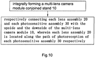
- According to another aspect of the present invention, the present invention also provides a method for avoiding two or more lens assemblies and two or more photosensitive assemblies of a multi-lens camera module from deviation, wherein the method comprises the following steps:
- (a) integrally forming a multi-lens camera module conjoined stand; and
- (b) connecting each of the lens assemblies and each of the photosensitive assemblies with the upside and the downside of the multi-lens camera module respectively, wherein each lens assembly is located along the path of photoreception of each photosensitive assembly respectively.
- According to a preferred embodiment of the present invention, the multi-lens camera module conjoined stand comprises at least one connecting body and at least two stand bodies, wherein each the stand body is extended from at least one of the connecting body, wherein the stand bodies support the lens assemblies and the photosensitive assemblies respectively. According to a preferred embodiment of the present invention, the multi-lens camera module conjoined stand comprises one connecting body and two stand bodies, wherein the stand bodies are symmetrically and integrally extended from the connecting body.
- Still further objects and advantages will become apparent from a consideration of the ensuing description and drawings.
- These and other objectives, features, and advantages of the present invention will become apparent from the following detailed description, the accompanying drawings, and the appended claims.
-
-
FIG. 1 is a sectional view of a conventional dual-lens camera module. -
FIG. 2 is a perspective view of a multi-lens camera module according to a preferred embodiment of the present invention. -
FIG. 3 is an exploded view of the multi-lens camera module according to the above preferred embodiment of the present invention. -
FIG. 4 is a sectional view of the multi-lens camera module according to the above preferred embodiment of the present invention. -
FIG. 5A is a perspective view at a visual angle of the multi-lens camera module conjoined stand according to the above preferred embodiment of the present invention. -
FIG. 5B is a perspective view at another visual angle of the multi-lens camera module conjoined stand according to the above preferred embodiment of the present invention. -
FIG. 6 is a comparison diagram of the rigid strength simulation of a conventional dual-lens camera module and the multi-lens camera module according to the present invention under stress. -
FIG. 7 is a perspective view of an alternative mode of the multi-lens camera module according to the preferred embodiment of the present invention. -
FIG. 8 is a sectional view of the alternative mode of the multi-lens camera module according to the preferred embodiment of the present invention. -
FIG. 9 is a perspective view of the alternative mode of the multi-lens camera module conjoined stand of the multi-lens camera module according to the preferred embodiment of the present invention. -
FIG. 10 is a flow chart illustrating a method for avoiding the imaging module of a multi-lens camera module from having deviation according to the preferred embodiment of the present invention. - The following details of the present invention are disclosed with the drawings and one or more embodiments in order that those skilled in the art can manufacture and utilize the present invention. Preferred embodiments in the following descriptions are to give examples only. Those skilled in the art can think of other obvious modifications. The basic notions defined in the following descriptions can apply to other implementations, substitutes, modifications, equivalences, and applications that do not deviate from the scope of the invention as defined by the claims.
- Referring to
Figures 2-5B , a multi-lens camera module according to a preferred embodiment of the present invention is illustrated, wherein the multi-lens camera module can be utilized in various electronic devices, so as to assist the user to shoot image of objects or persons through the multi-lens camera module. For example, the multi-lens camera module can be utilized to shoot imaging information, such as picture or video of objects, persons, and etc.. Preferably, the multi-lens camera module can be utilized in a mobile electronic device, which can be, for example but not limited to, a mobile phone or tablet. - Referring to
Figs. 2 and3 , the multi-lens camera module of the present invention is embodied as a dual-lens camera module in the following description to give examples for illustrating contents and advantages of the present invention. In particular, the dual-lens camera module can comprise a multi-lens camera module conjoinedstand 10, at least twolens assemblies 20, and at least twophotosensitive assemblies 30. Thelens assemblies 20 and thephotosensitive assemblies 30 are connected to different sides of the multi-lens camera module conjoined stand 10 respectively. Each of thelens assemblies 20 is positioned corresponding to a path of photoreception of one of thephotosensitive assemblies 30 so as to be arranged in a one-on-one manner. Besides, thephotosensitive assemblies 30 can be coupled with the electronic device. Person skilled in the art should understand that one of thelens assemblies 20 paired with one of thephotosensitive assemblies 30 can coordinate for capturing image. Specifically, light reflected from objects or persons and passed through thelens assemblies 20 will respectively be received by thephotosensitive assemblies 30 for photoelectric conversion. That is to say, thephotosensitive assemblies 30 can convert light signals into electrical signals and the electrical signals can be sent to the electronic device through thephotosensitive assemblies 30, so as for the electronic device to generate relative image of the objects or persons therefor. - The multi-lens camera module conjoined
stand 10 has anupside 101 and adownside 102. Theupside 101 and thedownside 102 of the multi-lens camera module conjoinedstand 10 are opposite to each other. Eachlens assembly 20 is connected with theupside 101 of the multi-lens camera module conjoinedstand 10. Eachphotosensitive assembly 30 is connected with thedownside 102 of the multi-lens camera module conjoinedstand 10. It is worth mentioning that, referring toFig. 4 , the side of the dual-lens camera module that is closer to the objects or persons being shot is defined as theupside 101 of the multi-lens camera module conjoinedstand 10. Oppositely, the side of the dual-lens camera module that is away from the objects or persons being shot is defined as thedownside 102 of the multi-lens camera module conjoinedstand 10. Therefore, it is understandable that when the dual-lens camera module is utilized in a mobile electronic device, such as mobile phone, digital camera and etc., and held on the user's hand, theupside 101 and thedownside 102 of the multi-lens camera module conjoinedstand 10 may have a front and back relationship rather than an up and down relationship in terms of spatial position. - According to the preferred embodiment, the multi-lens camera module conjoined
stand 10 comprises a connectingbody 11 and two standbodies 12, wherein thestand bodies 12 are integrally extended from the connectingbody 11, wherein each of thestand bodies 12 is utilized to support one of thelens assemblies 20 and one of thephotosensitive assemblies 30. Person skilled in the art should understand that, for the dual-lens camera module of the present invention, the connectingbody 11 of the multi-lens camera module conjoinedstand 10 and thestand bodies 12 are integrally formed, such that the multi-lens camera module conjoined stand 10 provided by the present invention is an integral body that can overcome the technical defects in the prior art, such as positional deviations and angle deviations between two independent stands, wherein the two separating stands are connected together by means of another element such as the circuit board. Moreover, the multi-lens camera module conjoined stand 10 can avoid relative tilt between the paths of photoreception of thelens assemblies 20 and thephotosensitive assemblies 30, so as to guarantee the consistency and imaging quality of the dual-lens camera module. - According to a preferred implementation of the present invention, each of the
lens assemblies 20 can comprise anoptical lens 21 directly connected on one of thestand bodies 12 of the multi-lens camera module conjoinedstand 10. In other words, according to this implementation, thelens assembly 20 is a fixed focus lens assembly, which means the focal length of thelens assembly 20 cannot be freely adjusted. Person skilled in the art should understand that theoptical lens 21 illustrated in the present invention can be directly connected with thestand body 12, which includes connecting theoptical lens 21 with thestand body 12 through a shell. - Besides, according to another preferred implementation of the present invention, each of the
lens assemblies 20 can also comprise a drivingmotor 22 connected with thestand body 12 of the multi-lens camera module conjoinedstand 10. Eachoptical lens 21 is drivably connected with the drivingmotor 22, such that the drivingmotor 22 can drive theoptical lens 21 to move along the path of photoreception of thephotosensitive assembly 30, so as to adjust the focal length of thelens assembly 20. That is to say, according to this implementation, thelens assemblies 20 are zoom lens assemblies, which mean the focal lengths of thelens assemblies 20 are adjustable. For instance, if a user is utilizing the dual-lens camera module to shoot image, he may adjust the shooting result through adjusting the focal lengths of thelens assemblies 20. - In addition, each of the
photosensitive assemblies 30 can comprise aphotosensitive sensor 31. The photosensitive side of thephotosensitive sensor 31 is facing theoptical lens 21 of thelens assembly 20 and an optic axis of theoptical lens 21 is perpendicular to the photosensitive side of thephotosensitive sensor 31, such that after the light passes through theoptical lens 21, the light can be received by the photosensitive side of thephotosensitive sensor 31 for subsequent photoelectric conversion. According to a preferred implementation of the present invention, the circuit of eachphotosensitive assembly 30 can be arranged on thephotosensitive sensor 31 and eachphotosensitive assembly 30 is coupled with the electronic device through the circuit. - According to another preferred implementation of the present invention, the
photosensitive assembly 30 may also comprise acircuit board 32, wherein eachphotosensitive sensor 31 can be electrically connected with thecircuit board 32. Thecircuit board 32 is coupled with the electronic device, such that thecircuit board 32 can be utilized to send the electrical signal generated by thephotosensitive sensor 31 through photoelectric conversion to the electronic device. For instance, thephotosensitive sensor 31 can be electrically connected to thecircuit board 32 by being attached on different positions of thecircuit board 32. - Besides, when sealing and packaging the dual-lens camera module, the
circuit board 32 is connected on the multi-lens camera module conjoinedstand 10 and thephotosensitive sensors 31 are corresponded to thestand bodies 12 respectively. For an exemplar illustration, after thephotosensitive sensor 31 was attached on thecircuit board 32, it can be electrically connected with thecircuit board 32 through at least a wire bond. Specifically, the dual-lens camera module provides at least a wire bond. The two ends of the wire bond are respectively extended to connect with the fringe of thephotosensitive sensor 31 and thecircuit board 32, so as to achieve the electrical connection between thephotosensitive sensor 31 and thecircuit board 32. Nevertheless, person skilled in the art should understand that the wire bond should not be the only feasible implementation for electrically connecting thephotosensitive sensor 31 and thecircuit board 32. For example, according to another feasible implementation of the present invention, thephotosensitive sensor 31 and thecircuit board 32 can also be welded and solder the solder balls. It is worth mentioning that, according to the dual-lens camera module of the present invention, the connection mode of thesensor 31 and thecircuit board 32 shall not limit the content and scope of the present invention. - It is worth mentioning that the
lens assemblies 20 of the dual-lens camera module can both be zoom lens assemblies. In other words, when thelens assemblies 20 and thephotosensitive assemblies 30 are both connected by the multi-lens camera module conjoinedstand 10, the distances between theoptical lenses 21 of thelens assemblies 20 and thesensors 31 of thephotosensitive assemblies 30 can be adjusted. For example, each of theoptical lenses 21 can be driven by the corresponding drivingmotor 22 so as to move along the path of photoreception of the correspondingphotosensitive sensor 31, such that the focal length of the dual-lens camera module can be adjusted through the shift between theoptical lens 21 and the photosensitive side of thephotosensitive sensor 31. It is understandable that according to a preferred implementation of the present invention, the relative positions of thelens assemblies 20 and thephotosensitive assemblies 30 can be synchronously adjusted. Nonetheless, according to another preferred implementation of the present invention, the relative positions of thelens assemblies 20 and thephotosensitive assemblies 30 can respectively be independently adjusted. - The
stand bodies 12 of the multi-lens camera module conjoinedstand 10 are integrally extended from two side portions of the connectingbody 11 respectively. Each standbody 12 is utilized to connect one of thelens assemblies 20 and one of thephotosensitive assemblies 30, so as to form the dual-lens camera module. The specification of thestand bodies 12 may not be limited. For instance, in one embodiment, the sizes of thestand bodies 12 can be different. For another preferred implementation of the present invention, the specifications of thestand bodies 12, including the dimensions, are all the same, which means thestand bodies 12 can be symmetrically extended to both sides of the connectingbody 11. - Further, each stand
body 12 has alight channel 121 to communicate theupside 101 and thedownside 102 of the multi-lens camera module conjoinedstand 10. Eachlens assembly 20 and eachphotosensitive assembly 30 of the dual-lens camera module can interact through the respectivelight channel 121 of each of thestand bodies 12. In other words, when the dual-lens camera module is shooting image, light can successively pass through theoptical lenses 21 of the lens assemblies and thelight channels 121 and be received by the photosensitive sides of thephotosensitive sensors 31 of thephotosensitive assemblies 30 for photoelectric conversion. It is worth mentioning that thelight channel 121 is arranged in the central position of each of thestand bodies 12. - Each stand
body 12 can further comprise aloading portion 122, a connectingportion 123 and an attachingportion 124, which are integrated or integrally formed. Thelight channel 121 is arranged in theloading portion 122. It is understandable that theloading portion 122 is at the inner side of thestand body 12, the attachingportion 124 is at the outer side of thestand body 12, and the connectingportion 123 is for connecting theloading portion 122 and the attachingportion 124. In other words, theloading portion 122, the connectingportion 123 and the attachingportion 124 are arranged on thestand body 12 along an internal to external manner. - A thickness dimension of the
loading portion 122 is smaller than the thickness dimension of the connectingportion 123 along the direction of the path of photoreception of the respectivephotosensitive sensor 31, such that thestand body 12 can form astair 1221 at the place corresponding to theloading portion 122. The dual-lens camera module also comprises at least two filteringelements 40 arranged on thestairs 1221 formed by theloading portions 122 to be supported by theloading portions 122 respectively. It is worth mentioning that the position of thestair 1221 formed by theloading portion 122 can be limited. For example, thestair 1221 formed by theloading portion 122 may be arranged on either theupside 101 of the multi-lens camera module conjoined stand 10 or thedownside 102 of the multi-lens camera module conjoinedstand 10. - The thickness dimension of the connecting
portion 123 is also smaller than the thickness dimension of the attachingportion 124 along the direction of the path of photoreception of thephotosensitive sensor 31, so as to respectively form afirst packaging groove 125 and asecond packaging groove 126 of thestand body 12 at a position corresponding to the connectingportion 123. Thefirst packaging groove 125 is on theupside 101 of the multi-lens camera module conjoinedstand 10, while thesecond packaging groove 126 is on thedownside 102 of the multi-lens camera module conjoinedstand 10. Person skilled in the art should understand that thefirst packaging groove 125 and thesecond packaging groove 126 are respectively communicated with thelight channel 121. Thelens assembly 20 can be corresponding to thefirst packaging groove 125 of thestand body 12 and sealed and packaged on the multi-lens camera module conjoinedstand 10. Thephotosensitive assembly 30 can be corresponding to thesecond packaging groove 126 of thestand body 12 and sealed and packaged on the multi-lens camera module conjoinedstand 10. - In particular, a side of the
lens assembly 20 can be sealed and packaged on thestand body 12 corresponding to thefirst packaging groove 125. For instance, the side of thelens assembly 20 may comprise a guide pin arranged on the side and extended into thefirst packaging groove 125, so as to implement the sealing and packaging of thelens assembly 20 and thestand body 10. According to the preferred embodiment, thecircuit board 32 of thephotosensitive assembly 30 can be attached on the attachingportion 124 of thestand body 12, so as to seal and package thephotosensitive sensor 31 of thecircuit board 32 in thesecond packaging groove 126 of thestand body 12 and to arrange the optic axis of theoptical lens 21 of thelens assembly 20 being perpendicular to the photosensitive side of thephotosensitive sensor 31 of thephotosensitive assembly 30. It is worth mentioning that, according to an alternative mode of the preferred embodiment of the present invention, the periphery of thesensor 31 of thephotosensitive assembly 30 can be extended for being sealed and packaged on the attachingportion 124 directly. Besides, thephotosensitive sensor 31 is positioned in thesecond packaging groove 126. - Person skilled in the art should understand that the multi-lens camera module conjoined
stand 10 is an integral body. Contrasting to the prior art that two or more independent stands are connected to form a stand of the dual-lens camera module, the integral multi-lens camera module conjoined stand 10 of the present invention provides the following outstanding advantages. - Specifically, a first advantage of the multi-lens camera module conjoined
stand 10 is that the multi-lens camera module conjoined stand 10 can overcome the technical defects of the independent stands of conventional dual-lens camera module, such as positional deviations and angle deviations between the independent stands when connecting the separate stands and etc., so as to avoid relative tilt between the paths of photoreception of thelens assemblies 20 and thephotosensitive assemblies 30 after sealing and packaging. - A second advantage of the multi-lens camera module conjoined
stand 10 is that when the dual-lens camera module of the present invention experiences severely shaken and vibration, thestand bodies 12 integrally extended from the connectingbody 11 can retain and ensure the relative positions of thelens assemblies 20 and thephotosensitive assemblies 30, such as the tilt, distance, and etc., among thelens assemblies 20 and thephotosensitive assemblies 30. - A third advantage of the multi-lens camera module conjoined
stand 10 is the thinner thickness thereof. The independent stands of the conventional art are connected by means of the circuit board. Therefore, in order to ensure the stability of the relative positions of the stands, a circuit board with certain thickness and rigidity is required for conventional multi-lens camera module. For example, the conventional dual-lens camera module can only utilize a PCB type circuit board that undoubtedly increases the thickness thereof. However, thecircuit board 32 of the dual-lens camera module of the present invention does not need to have to connect the stands. Therefore, there is no necessary requirement to the thickness and hardness of thecircuit board 32. For example, according to the present invention, thecircuit board 32 can be a PCB type circuit board or a FPC circuit board with even thinner thickness. Furthermore, according to an alternative mode of the preferred embodiment of the present invention, the dual-lens camera module may even do not include thecircuit board 32, but simply integrate the circuit into thephotosensitive sensors 31, so as to greatly reduce the thickness of the dual-lens camera module in the direction of the path of photoreception of thephotosensitive sensors 31, which allows the dual-lens camera module to be utilized on the electronic devices expected to be lighter and thinner. - Besides, person skilled in the art should understand that the conventional independent stands can only be connected through the circuit board, so a space has to be reserved between adjacent stands for accommodating the electronic components attached on the circuit board. Unfortunately, when the conventional dual-lens camera module is in use, the circuit board could be heated and deformed easily. Once the circuit board is deformed, the slopes of the independent stands will inevitably be changed, which will consequently impact the imaging quality of the conventional dual-lens camera module.
- According to the preferred embodiment of the present invention, the connecting
body 11 of the multi-lens camera module conjoined stand 10 further has an electronic componentaccommodating cavity 111 provided therein for accommodating and receiving one or moreelectronic components 321 attached on thecircuit board 32. The electronic componentaccommodating cavity 111 of the connectingbody 11 is impassable to thelight channel 121, thefirst packaging groove 125 and thesecond packaging groove 126 of thestand body 12. After thecircuit board 32 is attached on the multi-lens camera module conjoinedstand 10 during the process of sealing and packaging the dual-lens camera module, theelectronic component 321 is adapted to be sealed and packaged within the electronic componentaccommodating cavity 111 of the connectingbody 11 alone, such that the pollutants, such as welding slags, dusts, and etc., will not enter thesecond packaging groove 126 of thestand body 12 to pollute the photosensitive side of thephotosensitive sensor 31 of thephotosensitive assembly 30 sealed and packaged in thesecond packaging groove 126 of thestand body 12, that avoids defective pixel from occurring on the photosensitive side of thesensor 31 so as to further increase the imaging quality of the dual-lens camera module. - Also, the electronic component
accommodating cavity 111 of the connectingbody 11 is formed in a gap adjacent to thestand bodies 12, which not only utilizes spare space of the dual-lens camera module, but also avoids being deformed easily due to the fact that the electronic componentaccommodating cavity 111 of the connectingbody 11 prevents the stress of the multi-lens camera module conjoined stand 10 from concentrating because of the position of the connectingbody 11 , such that a stability of the multi-lens camera module conjoined stand in use is ensured. - As shown in the drawings, each of the
stand bodies 12 of the multi-lens camera module conjoinedstand 10 has a central axis and the distance between the central axes of thestand bodies 12 can be ranged 5mm to 200mm. Preferably, according to the preferred embodiment, the distance between the central axes of thestand bodies 12 can be 9mm. In addition, the alignment between the central axes of thestand bodies 12 is parallel or perpendicular to each fringe of the multi-lens camera module conjoinedstand 10, so that when the dual-lens camera module assembled with the multi-lens camera module conjoinedstand 10, thelens assemblies 20 and thephotosensitive assemblies 30 is installed in the electronic device, the path of photoreception of each of thelens assemblies 20 and each of thephotosensitive assemblies 30 can be controlled more easily. - There are essential differences between the dual-lens camera module of the present invention and the conventional dual-lens camera module in view of structures, technical effects, or etc.. The conventional dual-lens camera module needs to affix two independent stands on the circuit board but, based on its assembling process, the distance between the central axes of the two independent stands of the conventional dual-lens camera module is very difficult to be controlled, which renders a poor consistency of the dual-lens camera module according to conventional art. From a structural perspective, the two independent stands of the conventional dual-lens camera module are only affixed by the circuit board. In other words, the conventional dual-lens camera module depends on the circuit board for symmetrically securing two independent stands on the circuit board. During the application of the conventional dual-lens camera module, once distortion occurs on the circuit board, the positional relation between the two independent stands will inevitably be changed, which will render deadly impact to the imaging quality of the conventional dual-lens camera module. Moreover, the circuit board of the conventional dual-lens camera module is PCB in practical application, which is insufficient to support two or more independent stands, two or more lens assemblies, and two or more photosensitive assemblies. Also, PCB type circuit board can easily be deformed under heat. Besides, more and more lens assemblies and photosensitive assemblies are demanded in the multi-lens camera module, whereas the structure of conventional stand is more inadequate in making a multi-lens camera module that has more than two stands, two lens assemblies, and two photosensitive assemblies.
- According to a preferred implementation of the present invention, the multi-lens camera module conjoined stand 10 can be integrally formed by thermoplastic resin material that reinforces the stability of the multi-lens camera module conjoined
stand 10. According to an alternative mode of the preferred implementation of the present invention, the multi-lens camera module conjoinedstand 10 may also be integrally formed by engineering plastics, wherein the material formed by engineering plastics particles can be poured into the mold to produce the multi-lens camera module conjoinedstand 10. Specifically speaking, the material of the multi-lens camera module conjoinedstand 10 may be "ishiNTB982" engineering plastics, Liquid Crystal Polymer (LCP) engineering plastics, or etc. Besides, the multi-lens camera module conjoined stand 10 can also be made of metallic material or alloy material, so as to not only guarantee the intensity of the multi-lens camera module conjoinedstand 10, but also enhance the heat dissipation of the multi-lens camera module conjoinedstand 10. Specifically, the multi-lens camera module conjoined stand 10 can be integrally formed by metal powder or mixture of metal powder and nonmetal powder through injection molding technology or 3D printing technology. For instance, the material of the multi-lens camera module conjoined stand 10 can be aluminum alloy, zinc alloy, or etc. - It is worth mentioning that, in contrasting with the conventional dual-lens camera module, the multi-lens camera module conjoined stand 10 of the present invention provides a new thought of heat dissipation for the dual-lens camera module. That is, the present invention utilizes the multi-lens camera module conjoined stand 20 arranged on the circumferential of the
photosensitive sensors 31 of thephotosensitive assemblies 30 to implement heat dissipation. Firstly, the multi-lens camera module conjoinedstand 10 has a bigger radiating surface that can increase the heat dissipation performance of the dual-lens camera module. Secondly, none or only a small portion of the heat generated by thephotosensitive sensors 31 of thephotosensitive assemblies 30 has to be dissipated through thecircuit board 32. Therefore, thecircuit board 32 is not likely to be deformed due to high temperature and there is no need to attach radiating fin on the outer side of thecircuit board 32 as a heat dissipation aid, such that the thickness of the dual-lens camera module in the direction of the path of photoreception can further be reduced, which makes the dual-lens camera module especially suitable for the electronic devices expected to be lighter and thinner. -
Fig. 6 is a comparison diagram of the rigid strength simulation of a conventional dual-lens camera module and the dual-lens camera module according to the present invention under stress. Person skilled in the art should understand that, in contrasting with the independent stands of the conventional dual-lens camera module that rely on wire bonding, the multi-lens camera module conjoined stand 10 of the dual-lens camera module of the present invention utilizes an integral structure, which significantly strengthens the rigidity thereof. By testing the overall rigidity of the conventional dual-lens camera module and the dual-lens camera module of the present invention under stress, person skilled in the art would appreciate that it takes significantly greater external force to apply on the dual-lens camera module of the present invention than the conventional dual-lens camera module in order to trigger the same distortion thereon. For instance, referring toFig. 6 , it respectively changes the angle of the optic axes of the conventional dual-lens camera module and the multi-lens camera module of the present invention for 0.5°. During the testing, it applies external force to the stands of the right inFig. 6 so as to change the angle of the optic axes of the lens assemblies supported thereby. Therefore, the degree of distortion will gradually be greater for the position more to the right side of the independent stands and less for the position more to the left side of the independent stands. The test results indicate that the required external force to apply on the conventional dual-lens camera module for changing the angle of its optic axis for 0.5° is 1.17N, while the required external force to apply on the dual-lens camera module of the present invention for changing the angle of its optic axis for 0.5° is 11.8N. Hence, the test results have revealed that the overall rigidity of the dual-lens camera module of the present invention is far greater than the overall rigidity of the conventional dual-lens camera module, which means the dual-lens camera module of the present invention is more stable. - Person skilled in the art should understand that the multi-lens camera module being embodied as the dual-lens camera module in the above description of the present invention is just an example for describing and illustrating the content and scope of the present invention. Practically, the multi-lens camera module conjoined
stand 10 may also provide three ormore stand bodies 12, so as to implement the multi-lens camera module beyond the dual-lens camera module, where the multi-lens camera module, for example, may be embodied as a tri-lens camera module, tetra-lens camera module, and etc.. This is beyond the expectation of the dual-lens camera module of prior art and the structure of the conventional dual-lens camera module is not able to provide any technical inspiration on the multi-lens camera module of the present invention. Hence, the multi-lens camera module of the present invention has significant non-obviousness. - According to the alternative modes of the preferred embodiment as illustrated in
Figs. 7-9 , the multi-lens camera module can comprise one integrated multi-lens camera module conjoinedstand 10, six thelens assemblies 20 and six thephotosensitive assemblies 30, wherein the multi-lens camera module conjoinedstand 10 provides sixstand bodies 12, where each one of thestand bodies 12 is utilized to support one of thelens assemblies 20 and one of thephotosensitive assemblies 30 so as to form the multi-lens camera module. It is worth mentioning that the correspondingly alignedlens assemblies 20 andphotosensitive assemblies 30 are arranged into an array manner, where the multi-lens camera module forming an array camera module. - It is worth mentioning that, referring to
Fig. 10 , the present invention also provides a method for avoiding thelens assemblies 20 and thephotosensitive assemblies 30 of the multi-lens camera module from deviation, wherein the method comprises the following steps: - (a) integrally forming a multi-lens camera module conjoined
stand 10; and - (b) connecting the
lens assemblies 20 on upside and thephotosensitive assembly 30 on the downside of the multi-lens camera module conjoinedstand 10, wherein thelens assemblies 20 are located along the paths of photoreception of thephotosensitive assemblies 30 respectively. - Those skilled in the art shall understand that the above mentioned embodiments of the present invention in the descriptions and figures are exemplary only and not intended to be limiting.
- Accordingly, objectives of the present invention are completely and effectively implemented. Notions of the functions and structures of the present invention have been shown and described in the embodiments, while the present invention shall not be limited to the change of the basis of the notions of the embodiments, without departing from the scope of the invention as defined by the claims.
Claims (15)
- A multi-lens camera module, comprising:at least two lens assemblies (20), wherein each of the lens assemblies (20) comprises an optical lens (21); andat least two photosensitive assemblies (30), wherein each of the photosensitive assemblies (30) comprises a photosensitive sensor (31) and a circuit board (32);characterized in that the multi-lens camera module comprises an integrated multi-lens camera module conjoined stand (10) having an upside (101) and a downside (102); wherein said lens assemblies (20) are connected with said upside (101) of said multi-lens camera module conjoined stand (10), with the respective optical lens (21) being directly connected with said multi-lens camera module conjoined stand (10) so as to form a fixed focus lens assembly, or alternatively, when each of the lens assemblies (20) also comprises a driving motor (22), with the respective driving motor (22) being connected with said multi-lens camera module conjoined stand (10) so as to form a zoom lens assembly; and said photosensitive assemblies (30) are connected with said downside (102) of said multi-lens camera module conjoined stand (10), with the respective circuit board (32) being attached on the integrated multi-lens camera module conjoined stand (10); wherein said lens assemblies (20) are located along paths of photoreception of said photosensitive assemblies (30) respectively.
- The multi-lens camera module, as recited in claim 1, characterized in that said multi-lens camera module conjoined stand (10) comprises at least a connecting body (11) and at least two stand bodies (12), wherein each of said stand bodies (12) is extended from at least one said connecting body (11), wherein each of said stand bodies (12) supports one of said lens assemblies (20) and one of said photosensitive assemblies (30).
- The multi-lens camera module, as recited in claim 1, characterized in that said multi-lens camera module conjoined stand (10) comprises one connecting body (11) and at least two stand bodies (12), wherein said stand bodies (12) are symmetrically and integrally extended from said connecting body (11), wherein each of said stand bodies (12) supports one of said lens assemblies (20) and one of said photosensitive assemblies (30).
- The multi-lens camera module, as recited in claim 3, characterized in that each of said stand bodies (12) has a light channel (121), a first packaging groove (125) and a second packaging groove (126) communicated with said light channel (121), wherein said lens assemblies (20) are positioned corresponding to said first packaging grooves (125) respectively and connected with said upside (101) of said multi-lens camera module conjoined stand (10), wherein said photosensitive assemblies (30) are positioned corresponding to said second packaging grooves (126) respectively and connected with said downside (102) of said multi-lens camera module conjoined stand (10).
- The multi-lens camera module, as at least recited in claim 1, characterized in that said multi-lens camera module conjoined stand (10) has at least two light channels (121), at least two first packaging grooves (125) and at least two second packaging grooves (126), wherein said first packaging grooves (125) and said second packaging grooves (126) are respectively communicated with said light channels (121), wherein said lens assemblies (20) are positioned corresponding to said first packaging grooves (125) respectively and connected with said upside (101) of said multi-lens camera module conjoined stand (10), wherein said photosensitive assemblies (30) are positioned corresponding to said second packaging grooves (126) respectively and connected with said downside (102) of said multi-lens camera module conjoined stand (10).
- The multi-lens camera module, as recited in claim 4, characterized in that each of said stand bodies (12) comprises a connecting portion (123) and an attaching portion (124), wherein said attaching portion (124) is extended from said stand body (12) and said connecting portion (123) is extended from an inner side of said attaching portion (124), wherein a thickness dimension of said connecting portion (123) is smaller than a thickness dimension of said attaching portion (124) , so as to form said first packaging groove (125) and said second packaging groove (126) on two side portions of said connecting portion (123) respectively along a thickness direction of said multi-lens camera module.
- The multi-lens camera module, as recited in claim 6, characterized in that each of said stand bodies (12) comprises a loading portion (122) extended from an inner side of said connecting portion (123), wherein said loading portion (122) defines said light channel (121), wherein a thickness dimension of said loading portion (122) is smaller than a thickness dimension of said connecting portion (123) so as to form a stair (1221) on a side of said connecting portion (123) along the thickness direction of said multi-lens camera module.
- The multi-lens camera module, as recited in claim 7, characterized in that the multi-lens camera module further comprises at least two filtering elements (40) arranged on said stairs (1221) formed by said loading portions (122) respectively.
- The multi-lens camera module, as recited in claim 7, characterized in that said stairs (1221) and said first packaging grooves (125) are provided on the same side of the multi-lens camera module conjoined stand (10).
- The multi-lens camera module, as recited in claim 7, characterized in that said stairs (1221) and said second packaging grooves (126) are provided on the same side of the multi-lens camera module conjoined stand (10).
- The multi-lens camera module, as recited in claim 7, characterized in that said connecting body (11) has an electronic component accommodation cavity (111) provided therein, wherein said electronic component accommodation cavity (111) is impassable to said first packaging groove (125), said second packaging groove (126) and said light channel (121), wherein each of said photosensitive sensors (31) of said photosensitive assemblies (30) is electrically connected with said circuit board (32), wherein said circuit board (32) comprises at least an electronic component (321), wherein said circuit board (32) is adaptable for being attached on said downside (102) of said multi-lens camera module conjoined stand (10), wherein said photosensitive sensors (31) are packaged and sealed in said second packaging grooves (126) respectively, wherein said electronic component (321) is packaged and sealed in said electronic component accommodation cavity (111), wherein said electronic component accommodating cavity (111) and said second packaging grooves (126) are on the same side of the multi-lens camera module conjoined stand (10).
- The multi-lens camera module, as recited in claim 11, characterized in that said circuit board (32) is selected from the group consisting of a PCB type circuit board and a FPC type circuit board.
- The multi-lens camera module, as recited in claim 7, characterized in that a range of a distance between central axes of said stand bodies (12) is 5mm-200mm.
- The multi-lens camera module, as recited in claim 13, characterized in that said range of said distance between said central axes of said stand bodies (12) is 9mm.
- The multi-lens camera module, as recited in claim 7, characterized in that a material of said multi-lens camera module conjoined stand (10) is selected from the group consisting of thermoplastic resin, engineering plastics, metal, alloy, aluminum alloy, zinc alloy, metal powder and mixture of metal powder and nonmetal powder.
Applications Claiming Priority (2)
| Application Number | Priority Date | Filing Date | Title |
|---|---|---|---|
| CN201510472665.7A CN105187697B (en) | 2015-08-04 | 2015-08-04 | Multi-lens camera module conjoined bracket, multi-lens camera module and application thereof |
| PCT/CN2016/091714 WO2017020751A1 (en) | 2015-08-04 | 2016-07-26 | Multi-lens camera module conjoined stand, multi-lens camera module and application thereof |
Publications (3)
| Publication Number | Publication Date |
|---|---|
| EP3334145A1 EP3334145A1 (en) | 2018-06-13 |
| EP3334145A4 EP3334145A4 (en) | 2019-03-20 |
| EP3334145B1 true EP3334145B1 (en) | 2021-03-31 |
Family
ID=54909527
Family Applications (1)
| Application Number | Title | Priority Date | Filing Date |
|---|---|---|---|
| EP16832239.4A Active EP3334145B1 (en) | 2015-08-04 | 2016-07-26 | Multi-lens camera module conjoined stand, multi-lens camera module and application thereof |
Country Status (5)
| Country | Link |
|---|---|
| US (1) | US11627384B2 (en) |
| EP (1) | EP3334145B1 (en) |
| JP (2) | JP7059181B2 (en) |
| CN (1) | CN105187697B (en) |
| WO (1) | WO2017020751A1 (en) |
Families Citing this family (60)
| Publication number | Priority date | Publication date | Assignee | Title |
|---|---|---|---|---|
| CN105187697B (en) | 2015-08-04 | 2019-12-31 | 宁波舜宇光电信息有限公司 | Multi-lens camera module conjoined bracket, multi-lens camera module and application thereof |
| CN205545565U (en) * | 2015-12-30 | 2016-08-31 | 南昌欧菲光电技术有限公司 | Imaging module and electron device |
| CN107155041A (en) * | 2016-03-03 | 2017-09-12 | 南昌欧菲光电技术有限公司 | Imaging modules and electronic installation |
| CN107155042A (en) * | 2016-03-03 | 2017-09-12 | 南昌欧菲光电技术有限公司 | Imaging modules and electronic installation |
| CN107155025A (en) * | 2016-03-03 | 2017-09-12 | 南昌欧菲光电技术有限公司 | Imaging modules and electronic installation |
| CN107155040A (en) * | 2016-03-03 | 2017-09-12 | 南昌欧菲光电技术有限公司 | Imaging modules and electronic installation |
| CN107155029A (en) * | 2016-03-03 | 2017-09-12 | 南昌欧菲光电技术有限公司 | Imaging modules and electronic installation |
| CN107155021A (en) * | 2016-03-03 | 2017-09-12 | 南昌欧菲光电技术有限公司 | Imaging modules and electronic installation |
| CN107155043A (en) * | 2016-03-03 | 2017-09-12 | 南昌欧菲光电技术有限公司 | Imaging modules and electronic installation |
| CN107155046A (en) * | 2016-03-03 | 2017-09-12 | 南昌欧菲光电技术有限公司 | Imaging modules and electronic installation |
| WO2017113749A1 (en) * | 2015-12-30 | 2017-07-06 | 深圳欧菲光科技股份有限公司 | Imaging module and electronic device |
| CN107155028A (en) * | 2016-03-03 | 2017-09-12 | 南昌欧菲光电技术有限公司 | Imaging modules and electronic installation |
| CN107155024A (en) * | 2016-03-03 | 2017-09-12 | 南昌欧菲光电技术有限公司 | Imaging modules and electronic installation |
| CN108702431A (en) * | 2016-02-18 | 2018-10-23 | 宁波舜宇光电信息有限公司 | Array camera module and its molding photosensory assembly, circuit board module and manufacturing method and electronic equipment |
| JP7005505B2 (en) * | 2016-02-18 | 2022-01-21 | ニンボー サニー オプテック カンパニー,リミテッド | Manufacturing methods for array imaging modules and molded photosensitive assemblies, circuit board assemblies, and their electronic devices. |
| CN105898120B (en) * | 2016-04-21 | 2019-11-29 | 宁波舜宇光电信息有限公司 | Camera module based on moulding technology |
| CN107172325A (en) * | 2016-03-08 | 2017-09-15 | 南昌欧菲光电技术有限公司 | Dual camera module and electronic installation |
| US10750071B2 (en) | 2016-03-12 | 2020-08-18 | Ningbo Sunny Opotech Co., Ltd. | Camera module with lens array arrangement, circuit board assembly, and image sensor and manufacturing method thereof |
| CN105681637B (en) * | 2016-03-15 | 2019-12-31 | 宁波舜宇光电信息有限公司 | Array camera module and photosensitive assembly and manufacturing method thereof |
| EP3429181A4 (en) * | 2016-03-12 | 2019-09-18 | Ningbo Sunny Opotech Co., Ltd. | Array camera module, moulded photosensitive assembly and manufacturing method therefor, and electronic device |
| TWM559422U (en) * | 2016-03-15 | 2018-05-01 | Sunny Optical Tech Group Company Limited | Array camera module and its molded photosensitive assembly, circuit board assembly, and electronic device |
| EP3468165B1 (en) * | 2016-03-28 | 2023-12-20 | Ningbo Sunny Opotech Co., Ltd. | Camera module and molded photosensitive assembly and manufacturing method therefor, and electronic device |
| CN112217969B (en) * | 2016-04-07 | 2022-10-21 | 宁波舜宇光电信息有限公司 | Photosensitive device with reinforced circuit board, array camera module and manufacturing method thereof |
| TWI731060B (en) * | 2016-04-07 | 2021-06-21 | 大陸商寧波舜宇光電信息有限公司 | Split type array camera module and its assembling and application method |
| CN107302670B (en) * | 2016-04-07 | 2021-05-04 | 宁波舜宇光电信息有限公司 | Split type array camera module and assembling method |
| WO2017181668A1 (en) | 2016-04-21 | 2017-10-26 | 宁波舜宇光电信息有限公司 | Camera module and array camera module based on integration packaging process |
| CN106200250A (en) * | 2016-08-04 | 2016-12-07 | 捷开通讯(深圳)有限公司 | A kind of many camera lenses module and camera head |
| JP2019526833A (en) * | 2016-08-24 | 2019-09-19 | ハッチンソン テクノロジー インコーポレイテッドHutchinson Technology Incorporated | Dual camera assembly with optical image stabilization |
| TWI644157B (en) | 2016-09-12 | 2018-12-11 | 台灣東電化股份有限公司 | Optical element driving mechanism |
| KR102612541B1 (en) * | 2016-10-18 | 2023-12-12 | 엘지이노텍 주식회사 | Camera module |
| CN106790792B (en) * | 2016-12-08 | 2019-02-05 | Oppo广东移动通信有限公司 | Imaging modules and mobile terminal |
| CN106850882B (en) | 2016-12-20 | 2020-03-24 | Oppo广东移动通信有限公司 | Bracket component and mobile terminal |
| CN106850883B (en) * | 2016-12-20 | 2020-03-24 | Oppo广东移动通信有限公司 | Bracket component, functional module and mobile terminal |
| EP3562136A4 (en) * | 2016-12-23 | 2020-08-19 | Ningbo Sunny Opotech Co., Ltd. | Image-capturing module, circuit board assembly, manufacturing method, and electronic device provided with image-capturing module |
| CN108243296A (en) | 2016-12-23 | 2018-07-03 | 宁波舜宇光电信息有限公司 | Circuit board assemblies and camera module and its manufacturing method and the electronic equipment with camera module |
| CN106657753A (en) * | 2017-03-08 | 2017-05-10 | 信利光电股份有限公司 | Lens support and multi-camera module |
| CN109391750B (en) * | 2017-08-05 | 2023-05-12 | 宁波舜宇光电信息有限公司 | Fixed focus camera module |
| CN107277339A (en) * | 2017-08-10 | 2017-10-20 | 信利光电股份有限公司 | Electronic equipment and camera module |
| KR102371009B1 (en) | 2017-08-22 | 2022-03-07 | 삼성전자 주식회사 | Camera module including reinforcement members for supporting printed circuit board on which a plurality of image sensors are disposed and electronic device including the same |
| CN109905569A (en) * | 2017-12-07 | 2019-06-18 | 昆山丘钛微电子科技有限公司 | Cam device |
| CN107990108A (en) * | 2017-12-26 | 2018-05-04 | 上海摩软通讯技术有限公司 | For double stents taken the photograph, Split type supporting stand formula pair takes the photograph and assemble method |
| CN107948495B (en) * | 2018-01-12 | 2020-11-20 | 信利光电股份有限公司 | Subregion formation of image sensitization chip and module, camera device of making a video recording |
| CN209656975U (en) * | 2018-01-25 | 2019-11-19 | 台湾东电化股份有限公司 | Drive module and its driving mechanism |
| CN110233951B (en) * | 2018-03-06 | 2021-02-19 | Oppo广东移动通信有限公司 | Camera module, camera assembly and electronic device |
| CN108600438A (en) * | 2018-04-10 | 2018-09-28 | Oppo广东移动通信有限公司 | Supporting structure, in-out box and mobile terminal |
| CN108683752A (en) * | 2018-04-10 | 2018-10-19 | Oppo广东移动通信有限公司 | Holder, in-out box and terminal |
| CN108495021A (en) * | 2018-06-26 | 2018-09-04 | 宁波金晟芯影像技术有限公司 | A kind of dual camera |
| CN108833757B (en) * | 2018-07-10 | 2024-03-26 | 昆山丘钛微电子科技有限公司 | Camera module, manufacturing method of camera module and mobile terminal |
| TWI746881B (en) * | 2018-08-16 | 2021-11-21 | 先進光電科技股份有限公司 | Optical image capturing module、system and manufacturing method thereof |
| TWI771472B (en) * | 2018-08-16 | 2022-07-21 | 先進光電科技股份有限公司 | Optical image capturing module、system and manufacturing method thereof |
| TWI768103B (en) * | 2018-08-16 | 2022-06-21 | 先進光電科技股份有限公司 | Optical image capturing module、system and manufacturing method thereof |
| CN111147699B (en) * | 2018-11-02 | 2022-01-07 | 南昌欧菲光电技术有限公司 | Electronic equipment, camera device and mounting base thereof |
| CN111147700A (en) * | 2018-11-02 | 2020-05-12 | 南昌欧菲光电技术有限公司 | Camera device and intelligent terminal |
| DE102019101490A1 (en) * | 2019-01-22 | 2020-07-23 | Sick Ag | Modular camera device and method for optical detection |
| CN109714516A (en) * | 2019-02-19 | 2019-05-03 | 昆山丘钛微电子科技有限公司 | TOF camera module and electronic product |
| CN113519058A (en) | 2019-03-12 | 2021-10-19 | 索尼半导体解决方案公司 | Semiconductor device with a plurality of semiconductor chips |
| CN210137372U (en) * | 2019-07-23 | 2020-03-10 | RealMe重庆移动通信有限公司 | Camera support, camera assembly and electronic equipment |
| US11893668B2 (en) | 2021-03-31 | 2024-02-06 | Leica Camera Ag | Imaging system and method for generating a final digital image via applying a profile to image information |
| CN115122051A (en) * | 2022-06-24 | 2022-09-30 | 上海金池模具科技有限公司 | Processing method of single-mode laser lens adjusting frame |
| CN115325370B (en) * | 2022-10-17 | 2022-12-30 | 南京隼眼电子科技有限公司 | Mounting equipment and camera |
Family Cites Families (40)
| Publication number | Priority date | Publication date | Assignee | Title |
|---|---|---|---|---|
| JP2004048287A (en) | 2002-07-10 | 2004-02-12 | Konica Minolta Holdings Inc | Imaging apparatus and mobile terminal |
| US7619683B2 (en) * | 2003-08-29 | 2009-11-17 | Aptina Imaging Corporation | Apparatus including a dual camera module and method of using the same |
| US7324154B2 (en) * | 2004-11-23 | 2008-01-29 | Yi-Jen Cheng | Monitoring video camera |
| JP2007036393A (en) | 2005-07-22 | 2007-02-08 | Smk Corp | Camera module and manufacturing method thereof |
| JP2007306282A (en) | 2006-05-11 | 2007-11-22 | Citizen Electronics Co Ltd | Camera module |
| KR20080085444A (en) * | 2007-03-20 | 2008-09-24 | 엘지이노텍 주식회사 | Camera module |
| KR100860308B1 (en) | 2007-06-05 | 2008-09-25 | 삼성전기주식회사 | Camera module package and method of manufacturing the same |
| JP2009094648A (en) | 2007-10-04 | 2009-04-30 | Chunichi Denshi Co Ltd | Optical axis adjustment apparatus of compound-eye type camera |
| US20100259655A1 (en) * | 2007-11-01 | 2010-10-14 | Konica Minolta Holdings, Inc. | Imaging device |
| CN101770060B (en) * | 2008-12-27 | 2014-03-26 | 鸿富锦精密工业(深圳)有限公司 | Camera module and assembly method thereof |
| JP5158895B2 (en) | 2010-05-11 | 2013-03-06 | シャープ株式会社 | Imaging device |
| JP5063739B2 (en) * | 2010-05-21 | 2012-10-31 | Tdk株式会社 | Lens drive device |
| US20130141541A1 (en) * | 2010-06-11 | 2013-06-06 | Hysonic. Co., Ltd. | Compact camera actuator and compact stereo-scopic image photographing device |
| KR101140346B1 (en) * | 2010-08-31 | 2012-05-03 | 엘지이노텍 주식회사 | Dual camera device |
| KR101149021B1 (en) * | 2010-10-08 | 2012-05-24 | 엘지이노텍 주식회사 | Three Dimensional Image Pick-Up Device andManufacturing Method thereof |
| US9094592B2 (en) * | 2011-11-15 | 2015-07-28 | Lg Innotek Co., Ltd. | Camera module with foreign objects inhibiting structure |
| JP5701785B2 (en) * | 2012-02-03 | 2015-04-15 | 株式会社東芝 | The camera module |
| CN202652361U (en) * | 2012-05-28 | 2013-01-02 | 信利光电(汕尾)有限公司 | Dual camera module |
| US9097878B2 (en) * | 2013-05-03 | 2015-08-04 | Himax Technologies Limited | Image capture module |
| CN103336401B (en) * | 2013-07-03 | 2016-05-11 | 南昌欧菲光电技术有限公司 | Supporting structure and there is the camera module of this supporting structure |
| CN203416328U (en) * | 2013-07-26 | 2014-01-29 | 瑞声声学科技(苏州)有限公司 | Array type camera module group |
| US9496247B2 (en) * | 2013-08-26 | 2016-11-15 | Optiz, Inc. | Integrated camera module and method of making same |
| US9965856B2 (en) * | 2013-10-22 | 2018-05-08 | Seegrid Corporation | Ranging cameras using a common substrate |
| WO2015070105A1 (en) * | 2013-11-07 | 2015-05-14 | Pelican Imaging Corporation | Methods of manufacturing array camera modules incorporating independently aligned lens stacks |
| JP2015099262A (en) * | 2013-11-19 | 2015-05-28 | ソニー株式会社 | Solid state image sensor, camera module and an electronic apparatus |
| CN203745777U (en) * | 2014-01-10 | 2014-07-30 | 瑞声声学科技(深圳)有限公司 | Array type lens device |
| CN203788359U (en) * | 2014-03-05 | 2014-08-20 | 瑞声声学科技(苏州)有限公司 | Camera module |
| CN203933331U (en) * | 2014-04-30 | 2014-11-05 | 光宝电子(广州)有限公司 | Voice coil motor array module |
| CN204258922U (en) * | 2014-07-08 | 2015-04-08 | 江苏金成光电科技有限公司 | Mobile phone camera |
| US9674412B2 (en) | 2014-08-01 | 2017-06-06 | Flir Commercial Systems, Inc. | Multi-sensor camera with apertured circuit-carrying substrate |
| CN104349030B (en) * | 2014-11-28 | 2019-03-05 | Oppo广东移动通信有限公司 | Cam device and mobile terminal with the cam device |
| CN204422842U (en) * | 2014-12-19 | 2015-06-24 | 宁波舜宇光电信息有限公司 | A kind of camera module and adjustable motor bracket thereof |
| CN104834158B (en) * | 2015-05-22 | 2017-10-27 | 南昌欧菲光电技术有限公司 | Dual camera module |
| CN204633900U (en) * | 2015-06-05 | 2015-09-09 | 南昌欧菲光电技术有限公司 | A kind of dual camera module |
| CN105187697B (en) | 2015-08-04 | 2019-12-31 | 宁波舜宇光电信息有限公司 | Multi-lens camera module conjoined bracket, multi-lens camera module and application thereof |
| CN204993579U (en) * | 2015-08-04 | 2016-01-20 | 宁波舜宇光电信息有限公司 | Many camera lenses module disjunctor support and many camera lenses module of making a video recording of making a video recording |
| US9973669B2 (en) * | 2015-08-28 | 2018-05-15 | Apple Inc. | Dual overmolded reconstructed camera module |
| CN204948203U (en) | 2015-09-30 | 2016-01-06 | 信利光电股份有限公司 | A kind of dual camera module and electronic equipment |
| US9933601B2 (en) * | 2015-12-16 | 2018-04-03 | Intel Corporation | Stacked wafer lens and camera |
| US10728435B2 (en) * | 2017-06-23 | 2020-07-28 | Shoppertrak Rct Corporation | Image capture device with flexible circuit board |
-
2015
- 2015-08-04 CN CN201510472665.7A patent/CN105187697B/en active Active
-
2016
- 2016-07-26 JP JP2018526287A patent/JP7059181B2/en active Active
- 2016-07-26 US US15/750,200 patent/US11627384B2/en active Active
- 2016-07-26 WO PCT/CN2016/091714 patent/WO2017020751A1/en active Application Filing
- 2016-07-26 EP EP16832239.4A patent/EP3334145B1/en active Active
-
2021
- 2021-09-10 JP JP2021147950A patent/JP7419311B2/en active Active
Non-Patent Citations (1)
| Title |
|---|
| None * |
Also Published As
| Publication number | Publication date |
|---|---|
| EP3334145A1 (en) | 2018-06-13 |
| JP7419311B2 (en) | 2024-01-22 |
| JP7059181B2 (en) | 2022-04-25 |
| JP2018532352A (en) | 2018-11-01 |
| WO2017020751A1 (en) | 2017-02-09 |
| CN105187697A (en) | 2015-12-23 |
| EP3334145A4 (en) | 2019-03-20 |
| CN105187697B (en) | 2019-12-31 |
| US20210329149A1 (en) | 2021-10-21 |
| US11627384B2 (en) | 2023-04-11 |
| JP2022002396A (en) | 2022-01-06 |
Similar Documents
| Publication | Publication Date | Title |
|---|---|---|
| EP3334145B1 (en) | Multi-lens camera module conjoined stand, multi-lens camera module and application thereof | |
| US11706516B2 (en) | Camera module and array camera module with circuit board unit and photosensitive unit and manufacturing method thereof | |
| CN106790792B (en) | Imaging modules and mobile terminal | |
| TWI703715B (en) | Array camera module, molded photosensitive element and manufacturing method thereof, and electronic equipment | |
| WO2017140118A1 (en) | Array camera module, molded photosensitive component and circuit board component of same, manufacturing method therefor, and electronic device | |
| CN107065423B (en) | Three-dimensional image acquisition device and manufacturing method thereof | |
| CN204993579U (en) | Many camera lenses module disjunctor support and many camera lenses module of making a video recording of making a video recording | |
| TWI657306B (en) | Array camera module and molded photosensitive component thereof, circuit board assembly and manufacturing method, and electronic device | |
| US10192914B2 (en) | Camera module and array camera module with circuit board unit and photosensitive unit and manufacturing method thereof | |
| KR20170099764A (en) | Camera module with compression-molded circuit board and manufacturing method thereof | |
| CN104364908A (en) | Compact camera module | |
| TWI604258B (en) | Multi-camera module assembly bracket and multi-lens camera module and their application | |
| CN109068029A (en) | Imaging modules and electronic device | |
| JP5897328B2 (en) | Stereo camera and manufacturing method thereof | |
| US20220050358A1 (en) | Driving device, camera module and electronic device | |
| CN103685881A (en) | Camera module | |
| US10200578B2 (en) | Camera device and electronic device with the same | |
| JP2005176117A (en) | Imaging apparatus | |
| CN107040699A (en) | Image pickup apparatus | |
| CN206629149U (en) | A kind of photographing module and electronic installation | |
| CN206629143U (en) | A kind of photographing module and electronic installation | |
| TWI782787B (en) | Camera module, electronic device and vehicle device | |
| WO2012169363A1 (en) | Method for producing stereo camera and stereo camera | |
| US20220244507A1 (en) | Plastic light-folding element, imaging lens assembly module and electronic device | |
| CN206759578U (en) | A kind of photographing module and electronic installation |
Legal Events
| Date | Code | Title | Description |
|---|---|---|---|
| STAA | Information on the status of an ep patent application or granted ep patent |
Free format text: STATUS: THE INTERNATIONAL PUBLICATION HAS BEEN MADE |
|
| PUAI | Public reference made under article 153(3) epc to a published international application that has entered the european phase |
Free format text: ORIGINAL CODE: 0009012 |
|
| STAA | Information on the status of an ep patent application or granted ep patent |
Free format text: STATUS: REQUEST FOR EXAMINATION WAS MADE |
|
| 17P | Request for examination filed |
Effective date: 20180305 |
|
| AK | Designated contracting states |
Kind code of ref document: A1 Designated state(s): AL AT BE BG CH CY CZ DE DK EE ES FI FR GB GR HR HU IE IS IT LI LT LU LV MC MK MT NL NO PL PT RO RS SE SI SK SM TR |
|
| AX | Request for extension of the european patent |
Extension state: BA ME |
|
| DAV | Request for validation of the european patent (deleted) | ||
| DAX | Request for extension of the european patent (deleted) | ||
| A4 | Supplementary search report drawn up and despatched |
Effective date: 20190219 |
|
| RIC1 | Information provided on ipc code assigned before grant |
Ipc: G03B 17/12 20060101ALI20190213BHEP Ipc: H04N 5/225 20060101AFI20190213BHEP Ipc: G03B 17/02 20060101ALI20190213BHEP |
|
| STAA | Information on the status of an ep patent application or granted ep patent |
Free format text: STATUS: EXAMINATION IS IN PROGRESS |
|
| 17Q | First examination report despatched |
Effective date: 20200122 |
|
| GRAP | Despatch of communication of intention to grant a patent |
Free format text: ORIGINAL CODE: EPIDOSNIGR1 |
|
| STAA | Information on the status of an ep patent application or granted ep patent |
Free format text: STATUS: GRANT OF PATENT IS INTENDED |
|
| INTG | Intention to grant announced |
Effective date: 20201022 |
|
| GRAS | Grant fee paid |
Free format text: ORIGINAL CODE: EPIDOSNIGR3 |
|
| GRAA | (expected) grant |
Free format text: ORIGINAL CODE: 0009210 |
|
| STAA | Information on the status of an ep patent application or granted ep patent |
Free format text: STATUS: THE PATENT HAS BEEN GRANTED |
|
| AK | Designated contracting states |
Kind code of ref document: B1 Designated state(s): AL AT BE BG CH CY CZ DE DK EE ES FI FR GB GR HR HU IE IS IT LI LT LU LV MC MK MT NL NO PL PT RO RS SE SI SK SM TR |
|
| REG | Reference to a national code |
Ref country code: GB Ref legal event code: FG4D Ref country code: CH Ref legal event code: EP |
|
| REG | Reference to a national code |
Ref country code: AT Ref legal event code: REF Ref document number: 1378272 Country of ref document: AT Kind code of ref document: T Effective date: 20210415 |
|
| REG | Reference to a national code |
Ref country code: DE Ref legal event code: R096 Ref document number: 602016055373 Country of ref document: DE |
|
| REG | Reference to a national code |
Ref country code: IE Ref legal event code: FG4D |
|
| REG | Reference to a national code |
Ref country code: LT Ref legal event code: MG9D |
|
| PG25 | Lapsed in a contracting state [announced via postgrant information from national office to epo] |
Ref country code: BG Free format text: LAPSE BECAUSE OF FAILURE TO SUBMIT A TRANSLATION OF THE DESCRIPTION OR TO PAY THE FEE WITHIN THE PRESCRIBED TIME-LIMIT Effective date: 20210630 Ref country code: FI Free format text: LAPSE BECAUSE OF FAILURE TO SUBMIT A TRANSLATION OF THE DESCRIPTION OR TO PAY THE FEE WITHIN THE PRESCRIBED TIME-LIMIT Effective date: 20210331 Ref country code: HR Free format text: LAPSE BECAUSE OF FAILURE TO SUBMIT A TRANSLATION OF THE DESCRIPTION OR TO PAY THE FEE WITHIN THE PRESCRIBED TIME-LIMIT Effective date: 20210331 Ref country code: NO Free format text: LAPSE BECAUSE OF FAILURE TO SUBMIT A TRANSLATION OF THE DESCRIPTION OR TO PAY THE FEE WITHIN THE PRESCRIBED TIME-LIMIT Effective date: 20210630 |
|
| PG25 | Lapsed in a contracting state [announced via postgrant information from national office to epo] |
Ref country code: SE Free format text: LAPSE BECAUSE OF FAILURE TO SUBMIT A TRANSLATION OF THE DESCRIPTION OR TO PAY THE FEE WITHIN THE PRESCRIBED TIME-LIMIT Effective date: 20210331 Ref country code: RS Free format text: LAPSE BECAUSE OF FAILURE TO SUBMIT A TRANSLATION OF THE DESCRIPTION OR TO PAY THE FEE WITHIN THE PRESCRIBED TIME-LIMIT Effective date: 20210331 Ref country code: LV Free format text: LAPSE BECAUSE OF FAILURE TO SUBMIT A TRANSLATION OF THE DESCRIPTION OR TO PAY THE FEE WITHIN THE PRESCRIBED TIME-LIMIT Effective date: 20210331 |
|
| REG | Reference to a national code |
Ref country code: NL Ref legal event code: MP Effective date: 20210331 |
|
| REG | Reference to a national code |
Ref country code: AT Ref legal event code: MK05 Ref document number: 1378272 Country of ref document: AT Kind code of ref document: T Effective date: 20210331 |
|
| PG25 | Lapsed in a contracting state [announced via postgrant information from national office to epo] |
Ref country code: AT Free format text: LAPSE BECAUSE OF FAILURE TO SUBMIT A TRANSLATION OF THE DESCRIPTION OR TO PAY THE FEE WITHIN THE PRESCRIBED TIME-LIMIT Effective date: 20210331 Ref country code: NL Free format text: LAPSE BECAUSE OF FAILURE TO SUBMIT A TRANSLATION OF THE DESCRIPTION OR TO PAY THE FEE WITHIN THE PRESCRIBED TIME-LIMIT Effective date: 20210331 Ref country code: SM Free format text: LAPSE BECAUSE OF FAILURE TO SUBMIT A TRANSLATION OF THE DESCRIPTION OR TO PAY THE FEE WITHIN THE PRESCRIBED TIME-LIMIT Effective date: 20210331 Ref country code: EE Free format text: LAPSE BECAUSE OF FAILURE TO SUBMIT A TRANSLATION OF THE DESCRIPTION OR TO PAY THE FEE WITHIN THE PRESCRIBED TIME-LIMIT Effective date: 20210331 Ref country code: CZ Free format text: LAPSE BECAUSE OF FAILURE TO SUBMIT A TRANSLATION OF THE DESCRIPTION OR TO PAY THE FEE WITHIN THE PRESCRIBED TIME-LIMIT Effective date: 20210331 Ref country code: LT Free format text: LAPSE BECAUSE OF FAILURE TO SUBMIT A TRANSLATION OF THE DESCRIPTION OR TO PAY THE FEE WITHIN THE PRESCRIBED TIME-LIMIT Effective date: 20210331 |
|
| PG25 | Lapsed in a contracting state [announced via postgrant information from national office to epo] |
Ref country code: IS Free format text: LAPSE BECAUSE OF FAILURE TO SUBMIT A TRANSLATION OF THE DESCRIPTION OR TO PAY THE FEE WITHIN THE PRESCRIBED TIME-LIMIT Effective date: 20210731 Ref country code: PT Free format text: LAPSE BECAUSE OF FAILURE TO SUBMIT A TRANSLATION OF THE DESCRIPTION OR TO PAY THE FEE WITHIN THE PRESCRIBED TIME-LIMIT Effective date: 20210802 Ref country code: PL Free format text: LAPSE BECAUSE OF FAILURE TO SUBMIT A TRANSLATION OF THE DESCRIPTION OR TO PAY THE FEE WITHIN THE PRESCRIBED TIME-LIMIT Effective date: 20210331 Ref country code: RO Free format text: LAPSE BECAUSE OF FAILURE TO SUBMIT A TRANSLATION OF THE DESCRIPTION OR TO PAY THE FEE WITHIN THE PRESCRIBED TIME-LIMIT Effective date: 20210331 Ref country code: SK Free format text: LAPSE BECAUSE OF FAILURE TO SUBMIT A TRANSLATION OF THE DESCRIPTION OR TO PAY THE FEE WITHIN THE PRESCRIBED TIME-LIMIT Effective date: 20210331 |
|
| REG | Reference to a national code |
Ref country code: DE Ref legal event code: R097 Ref document number: 602016055373 Country of ref document: DE |
|
| PG25 | Lapsed in a contracting state [announced via postgrant information from national office to epo] |
Ref country code: ES Free format text: LAPSE BECAUSE OF FAILURE TO SUBMIT A TRANSLATION OF THE DESCRIPTION OR TO PAY THE FEE WITHIN THE PRESCRIBED TIME-LIMIT Effective date: 20210331 Ref country code: AL Free format text: LAPSE BECAUSE OF FAILURE TO SUBMIT A TRANSLATION OF THE DESCRIPTION OR TO PAY THE FEE WITHIN THE PRESCRIBED TIME-LIMIT Effective date: 20210331 Ref country code: DK Free format text: LAPSE BECAUSE OF FAILURE TO SUBMIT A TRANSLATION OF THE DESCRIPTION OR TO PAY THE FEE WITHIN THE PRESCRIBED TIME-LIMIT Effective date: 20210331 |
|
| PLBE | No opposition filed within time limit |
Free format text: ORIGINAL CODE: 0009261 |
|
| STAA | Information on the status of an ep patent application or granted ep patent |
Free format text: STATUS: NO OPPOSITION FILED WITHIN TIME LIMIT |
|
| REG | Reference to a national code |
Ref country code: CH Ref legal event code: PL |
|
| 26N | No opposition filed |
Effective date: 20220104 |
|
| PG25 | Lapsed in a contracting state [announced via postgrant information from national office to epo] |
Ref country code: MC Free format text: LAPSE BECAUSE OF FAILURE TO SUBMIT A TRANSLATION OF THE DESCRIPTION OR TO PAY THE FEE WITHIN THE PRESCRIBED TIME-LIMIT Effective date: 20210331 |
|
| REG | Reference to a national code |
Ref country code: BE Ref legal event code: MM Effective date: 20210731 |
|
| PG25 | Lapsed in a contracting state [announced via postgrant information from national office to epo] |
Ref country code: LI Free format text: LAPSE BECAUSE OF NON-PAYMENT OF DUE FEES Effective date: 20210731 Ref country code: CH Free format text: LAPSE BECAUSE OF NON-PAYMENT OF DUE FEES Effective date: 20210731 |
|
| PG25 | Lapsed in a contracting state [announced via postgrant information from national office to epo] |
Ref country code: IS Free format text: LAPSE BECAUSE OF FAILURE TO SUBMIT A TRANSLATION OF THE DESCRIPTION OR TO PAY THE FEE WITHIN THE PRESCRIBED TIME-LIMIT Effective date: 20210731 Ref country code: LU Free format text: LAPSE BECAUSE OF NON-PAYMENT OF DUE FEES Effective date: 20210726 |
|
| PG25 | Lapsed in a contracting state [announced via postgrant information from national office to epo] |
Ref country code: IT Free format text: LAPSE BECAUSE OF FAILURE TO SUBMIT A TRANSLATION OF THE DESCRIPTION OR TO PAY THE FEE WITHIN THE PRESCRIBED TIME-LIMIT Effective date: 20210331 Ref country code: IE Free format text: LAPSE BECAUSE OF NON-PAYMENT OF DUE FEES Effective date: 20210726 Ref country code: BE Free format text: LAPSE BECAUSE OF NON-PAYMENT OF DUE FEES Effective date: 20210731 |
|
| REG | Reference to a national code |
Ref country code: DE Ref legal event code: R079 Ref document number: 602016055373 Country of ref document: DE Free format text: PREVIOUS MAIN CLASS: H04N0005225000 Ipc: H04N0023000000 |
|
| PG25 | Lapsed in a contracting state [announced via postgrant information from national office to epo] |
Ref country code: HU Free format text: LAPSE BECAUSE OF FAILURE TO SUBMIT A TRANSLATION OF THE DESCRIPTION OR TO PAY THE FEE WITHIN THE PRESCRIBED TIME-LIMIT; INVALID AB INITIO Effective date: 20160726 |
|
| P01 | Opt-out of the competence of the unified patent court (upc) registered |
Effective date: 20230523 |
|
| PG25 | Lapsed in a contracting state [announced via postgrant information from national office to epo] |
Ref country code: CY Free format text: LAPSE BECAUSE OF FAILURE TO SUBMIT A TRANSLATION OF THE DESCRIPTION OR TO PAY THE FEE WITHIN THE PRESCRIBED TIME-LIMIT Effective date: 20210331 |
|
| PG25 | Lapsed in a contracting state [announced via postgrant information from national office to epo] |
Ref country code: GR Free format text: LAPSE BECAUSE OF FAILURE TO SUBMIT A TRANSLATION OF THE DESCRIPTION OR TO PAY THE FEE WITHIN THE PRESCRIBED TIME-LIMIT Effective date: 20210331 |
|
| PGFP | Annual fee paid to national office [announced via postgrant information from national office to epo] |
Ref country code: FR Payment date: 20230620 Year of fee payment: 8 |
|
| PGFP | Annual fee paid to national office [announced via postgrant information from national office to epo] |
Ref country code: GB Payment date: 20230601 Year of fee payment: 8 |
|
| PGFP | Annual fee paid to national office [announced via postgrant information from national office to epo] |
Ref country code: DE Payment date: 20230531 Year of fee payment: 8 |