EP3329175B1 - Schwenkbarer berührungsbildschirm für eine gasverteilungsanlage - Google Patents
Schwenkbarer berührungsbildschirm für eine gasverteilungsanlage Download PDFInfo
- Publication number
- EP3329175B1 EP3329175B1 EP16757286.6A EP16757286A EP3329175B1 EP 3329175 B1 EP3329175 B1 EP 3329175B1 EP 16757286 A EP16757286 A EP 16757286A EP 3329175 B1 EP3329175 B1 EP 3329175B1
- Authority
- EP
- European Patent Office
- Prior art keywords
- touchscreen
- region
- facility according
- working gas
- monitoring
- Prior art date
- Legal status (The legal status is an assumption and is not a legal conclusion. Google has not performed a legal analysis and makes no representation as to the accuracy of the status listed.)
- Active
Links
- 238000009826 distribution Methods 0.000 title claims description 58
- 230000004913 activation Effects 0.000 claims description 26
- 238000005259 measurement Methods 0.000 claims description 21
- 238000010586 diagram Methods 0.000 claims description 20
- 238000012544 monitoring process Methods 0.000 claims description 17
- 230000003213 activating effect Effects 0.000 claims description 7
- 238000011156 evaluation Methods 0.000 claims description 6
- 230000011664 signaling Effects 0.000 claims description 4
- 238000003860 storage Methods 0.000 claims description 4
- 239000007789 gas Substances 0.000 description 55
- 238000009434 installation Methods 0.000 description 47
- 238000010926 purge Methods 0.000 description 9
- 238000004891 communication Methods 0.000 description 5
- 238000001514 detection method Methods 0.000 description 4
- 238000009413 insulation Methods 0.000 description 4
- 238000000605 extraction Methods 0.000 description 3
- 238000000034 method Methods 0.000 description 3
- 210000000056 organ Anatomy 0.000 description 3
- 238000012423 maintenance Methods 0.000 description 2
- 238000012549 training Methods 0.000 description 2
- -1 for example Substances 0.000 description 1
- 231100001261 hazardous Toxicity 0.000 description 1
- 238000002955 isolation Methods 0.000 description 1
- 238000004519 manufacturing process Methods 0.000 description 1
- 238000005065 mining Methods 0.000 description 1
- 239000004065 semiconductor Substances 0.000 description 1
- 230000001988 toxicity Effects 0.000 description 1
- 231100000419 toxicity Toxicity 0.000 description 1
- 238000005303 weighing Methods 0.000 description 1
Images


Classifications
-
- F—MECHANICAL ENGINEERING; LIGHTING; HEATING; WEAPONS; BLASTING
- F17—STORING OR DISTRIBUTING GASES OR LIQUIDS
- F17C—VESSELS FOR CONTAINING OR STORING COMPRESSED, LIQUEFIED OR SOLIDIFIED GASES; FIXED-CAPACITY GAS-HOLDERS; FILLING VESSELS WITH, OR DISCHARGING FROM VESSELS, COMPRESSED, LIQUEFIED, OR SOLIDIFIED GASES
- F17C13/00—Details of vessels or of the filling or discharging of vessels
- F17C13/02—Special adaptations of indicating, measuring, or monitoring equipment
- F17C13/025—Special adaptations of indicating, measuring, or monitoring equipment having the pressure as the parameter
-
- F—MECHANICAL ENGINEERING; LIGHTING; HEATING; WEAPONS; BLASTING
- F17—STORING OR DISTRIBUTING GASES OR LIQUIDS
- F17C—VESSELS FOR CONTAINING OR STORING COMPRESSED, LIQUEFIED OR SOLIDIFIED GASES; FIXED-CAPACITY GAS-HOLDERS; FILLING VESSELS WITH, OR DISCHARGING FROM VESSELS, COMPRESSED, LIQUEFIED, OR SOLIDIFIED GASES
- F17C13/00—Details of vessels or of the filling or discharging of vessels
- F17C13/02—Special adaptations of indicating, measuring, or monitoring equipment
-
- F—MECHANICAL ENGINEERING; LIGHTING; HEATING; WEAPONS; BLASTING
- F17—STORING OR DISTRIBUTING GASES OR LIQUIDS
- F17C—VESSELS FOR CONTAINING OR STORING COMPRESSED, LIQUEFIED OR SOLIDIFIED GASES; FIXED-CAPACITY GAS-HOLDERS; FILLING VESSELS WITH, OR DISCHARGING FROM VESSELS, COMPRESSED, LIQUEFIED, OR SOLIDIFIED GASES
- F17C13/00—Details of vessels or of the filling or discharging of vessels
- F17C13/08—Mounting arrangements for vessels
- F17C13/084—Mounting arrangements for vessels for small-sized storage vessels, e.g. compressed gas cylinders or bottles, disposable gas vessels, vessels adapted for automotive use
-
- F—MECHANICAL ENGINEERING; LIGHTING; HEATING; WEAPONS; BLASTING
- F17—STORING OR DISTRIBUTING GASES OR LIQUIDS
- F17C—VESSELS FOR CONTAINING OR STORING COMPRESSED, LIQUEFIED OR SOLIDIFIED GASES; FIXED-CAPACITY GAS-HOLDERS; FILLING VESSELS WITH, OR DISCHARGING FROM VESSELS, COMPRESSED, LIQUEFIED, OR SOLIDIFIED GASES
- F17C7/00—Methods or apparatus for discharging liquefied, solidified, or compressed gases from pressure vessels, not covered by another subclass
- F17C7/02—Discharging liquefied gases
- F17C7/04—Discharging liquefied gases with change of state, e.g. vaporisation
-
- F—MECHANICAL ENGINEERING; LIGHTING; HEATING; WEAPONS; BLASTING
- F17—STORING OR DISTRIBUTING GASES OR LIQUIDS
- F17D—PIPE-LINE SYSTEMS; PIPE-LINES
- F17D3/00—Arrangements for supervising or controlling working operations
-
- G—PHYSICS
- G06—COMPUTING; CALCULATING OR COUNTING
- G06F—ELECTRIC DIGITAL DATA PROCESSING
- G06F3/00—Input arrangements for transferring data to be processed into a form capable of being handled by the computer; Output arrangements for transferring data from processing unit to output unit, e.g. interface arrangements
- G06F3/01—Input arrangements or combined input and output arrangements for interaction between user and computer
- G06F3/048—Interaction techniques based on graphical user interfaces [GUI]
- G06F3/0487—Interaction techniques based on graphical user interfaces [GUI] using specific features provided by the input device, e.g. functions controlled by the rotation of a mouse with dual sensing arrangements, or of the nature of the input device, e.g. tap gestures based on pressure sensed by a digitiser
- G06F3/0488—Interaction techniques based on graphical user interfaces [GUI] using specific features provided by the input device, e.g. functions controlled by the rotation of a mouse with dual sensing arrangements, or of the nature of the input device, e.g. tap gestures based on pressure sensed by a digitiser using a touch-screen or digitiser, e.g. input of commands through traced gestures
-
- F—MECHANICAL ENGINEERING; LIGHTING; HEATING; WEAPONS; BLASTING
- F17—STORING OR DISTRIBUTING GASES OR LIQUIDS
- F17C—VESSELS FOR CONTAINING OR STORING COMPRESSED, LIQUEFIED OR SOLIDIFIED GASES; FIXED-CAPACITY GAS-HOLDERS; FILLING VESSELS WITH, OR DISCHARGING FROM VESSELS, COMPRESSED, LIQUEFIED, OR SOLIDIFIED GASES
- F17C2201/00—Vessel construction, in particular geometry, arrangement or size
- F17C2201/03—Orientation
- F17C2201/032—Orientation with substantially vertical main axis
-
- F—MECHANICAL ENGINEERING; LIGHTING; HEATING; WEAPONS; BLASTING
- F17—STORING OR DISTRIBUTING GASES OR LIQUIDS
- F17C—VESSELS FOR CONTAINING OR STORING COMPRESSED, LIQUEFIED OR SOLIDIFIED GASES; FIXED-CAPACITY GAS-HOLDERS; FILLING VESSELS WITH, OR DISCHARGING FROM VESSELS, COMPRESSED, LIQUEFIED, OR SOLIDIFIED GASES
- F17C2201/00—Vessel construction, in particular geometry, arrangement or size
- F17C2201/05—Size
- F17C2201/056—Small (<1 m3)
-
- F—MECHANICAL ENGINEERING; LIGHTING; HEATING; WEAPONS; BLASTING
- F17—STORING OR DISTRIBUTING GASES OR LIQUIDS
- F17C—VESSELS FOR CONTAINING OR STORING COMPRESSED, LIQUEFIED OR SOLIDIFIED GASES; FIXED-CAPACITY GAS-HOLDERS; FILLING VESSELS WITH, OR DISCHARGING FROM VESSELS, COMPRESSED, LIQUEFIED, OR SOLIDIFIED GASES
- F17C2201/00—Vessel construction, in particular geometry, arrangement or size
- F17C2201/05—Size
- F17C2201/058—Size portable (<30 l)
-
- F—MECHANICAL ENGINEERING; LIGHTING; HEATING; WEAPONS; BLASTING
- F17—STORING OR DISTRIBUTING GASES OR LIQUIDS
- F17C—VESSELS FOR CONTAINING OR STORING COMPRESSED, LIQUEFIED OR SOLIDIFIED GASES; FIXED-CAPACITY GAS-HOLDERS; FILLING VESSELS WITH, OR DISCHARGING FROM VESSELS, COMPRESSED, LIQUEFIED, OR SOLIDIFIED GASES
- F17C2205/00—Vessel construction, in particular mounting arrangements, attachments or identifications means
- F17C2205/01—Mounting arrangements
- F17C2205/0103—Exterior arrangements
- F17C2205/0111—Boxes
-
- F—MECHANICAL ENGINEERING; LIGHTING; HEATING; WEAPONS; BLASTING
- F17—STORING OR DISTRIBUTING GASES OR LIQUIDS
- F17C—VESSELS FOR CONTAINING OR STORING COMPRESSED, LIQUEFIED OR SOLIDIFIED GASES; FIXED-CAPACITY GAS-HOLDERS; FILLING VESSELS WITH, OR DISCHARGING FROM VESSELS, COMPRESSED, LIQUEFIED, OR SOLIDIFIED GASES
- F17C2205/00—Vessel construction, in particular mounting arrangements, attachments or identifications means
- F17C2205/01—Mounting arrangements
- F17C2205/0123—Mounting arrangements characterised by number of vessels
- F17C2205/013—Two or more vessels
- F17C2205/0134—Two or more vessels characterised by the presence of fluid connection between vessels
- F17C2205/0146—Two or more vessels characterised by the presence of fluid connection between vessels with details of the manifold
-
- F—MECHANICAL ENGINEERING; LIGHTING; HEATING; WEAPONS; BLASTING
- F17—STORING OR DISTRIBUTING GASES OR LIQUIDS
- F17C—VESSELS FOR CONTAINING OR STORING COMPRESSED, LIQUEFIED OR SOLIDIFIED GASES; FIXED-CAPACITY GAS-HOLDERS; FILLING VESSELS WITH, OR DISCHARGING FROM VESSELS, COMPRESSED, LIQUEFIED, OR SOLIDIFIED GASES
- F17C2205/00—Vessel construction, in particular mounting arrangements, attachments or identifications means
- F17C2205/03—Fluid connections, filters, valves, closure means or other attachments
- F17C2205/0302—Fittings, valves, filters, or components in connection with the gas storage device
- F17C2205/0323—Valves
- F17C2205/0326—Valves electrically actuated
-
- F—MECHANICAL ENGINEERING; LIGHTING; HEATING; WEAPONS; BLASTING
- F17—STORING OR DISTRIBUTING GASES OR LIQUIDS
- F17C—VESSELS FOR CONTAINING OR STORING COMPRESSED, LIQUEFIED OR SOLIDIFIED GASES; FIXED-CAPACITY GAS-HOLDERS; FILLING VESSELS WITH, OR DISCHARGING FROM VESSELS, COMPRESSED, LIQUEFIED, OR SOLIDIFIED GASES
- F17C2205/00—Vessel construction, in particular mounting arrangements, attachments or identifications means
- F17C2205/03—Fluid connections, filters, valves, closure means or other attachments
- F17C2205/0302—Fittings, valves, filters, or components in connection with the gas storage device
- F17C2205/035—Flow reducers
-
- F—MECHANICAL ENGINEERING; LIGHTING; HEATING; WEAPONS; BLASTING
- F17—STORING OR DISTRIBUTING GASES OR LIQUIDS
- F17C—VESSELS FOR CONTAINING OR STORING COMPRESSED, LIQUEFIED OR SOLIDIFIED GASES; FIXED-CAPACITY GAS-HOLDERS; FILLING VESSELS WITH, OR DISCHARGING FROM VESSELS, COMPRESSED, LIQUEFIED, OR SOLIDIFIED GASES
- F17C2205/00—Vessel construction, in particular mounting arrangements, attachments or identifications means
- F17C2205/03—Fluid connections, filters, valves, closure means or other attachments
- F17C2205/0302—Fittings, valves, filters, or components in connection with the gas storage device
- F17C2205/0352—Pipes
-
- F—MECHANICAL ENGINEERING; LIGHTING; HEATING; WEAPONS; BLASTING
- F17—STORING OR DISTRIBUTING GASES OR LIQUIDS
- F17C—VESSELS FOR CONTAINING OR STORING COMPRESSED, LIQUEFIED OR SOLIDIFIED GASES; FIXED-CAPACITY GAS-HOLDERS; FILLING VESSELS WITH, OR DISCHARGING FROM VESSELS, COMPRESSED, LIQUEFIED, OR SOLIDIFIED GASES
- F17C2221/00—Handled fluid, in particular type of fluid
- F17C2221/03—Mixtures
- F17C2221/037—Containing pollutant, e.g. H2S, Cl
-
- F—MECHANICAL ENGINEERING; LIGHTING; HEATING; WEAPONS; BLASTING
- F17—STORING OR DISTRIBUTING GASES OR LIQUIDS
- F17C—VESSELS FOR CONTAINING OR STORING COMPRESSED, LIQUEFIED OR SOLIDIFIED GASES; FIXED-CAPACITY GAS-HOLDERS; FILLING VESSELS WITH, OR DISCHARGING FROM VESSELS, COMPRESSED, LIQUEFIED, OR SOLIDIFIED GASES
- F17C2223/00—Handled fluid before transfer, i.e. state of fluid when stored in the vessel or before transfer from the vessel
- F17C2223/01—Handled fluid before transfer, i.e. state of fluid when stored in the vessel or before transfer from the vessel characterised by the phase
- F17C2223/0146—Two-phase
- F17C2223/0153—Liquefied gas, e.g. LPG, GPL
-
- F—MECHANICAL ENGINEERING; LIGHTING; HEATING; WEAPONS; BLASTING
- F17—STORING OR DISTRIBUTING GASES OR LIQUIDS
- F17C—VESSELS FOR CONTAINING OR STORING COMPRESSED, LIQUEFIED OR SOLIDIFIED GASES; FIXED-CAPACITY GAS-HOLDERS; FILLING VESSELS WITH, OR DISCHARGING FROM VESSELS, COMPRESSED, LIQUEFIED, OR SOLIDIFIED GASES
- F17C2227/00—Transfer of fluids, i.e. method or means for transferring the fluid; Heat exchange with the fluid
- F17C2227/04—Methods for emptying or filling
- F17C2227/044—Methods for emptying or filling by purging
-
- F—MECHANICAL ENGINEERING; LIGHTING; HEATING; WEAPONS; BLASTING
- F17—STORING OR DISTRIBUTING GASES OR LIQUIDS
- F17C—VESSELS FOR CONTAINING OR STORING COMPRESSED, LIQUEFIED OR SOLIDIFIED GASES; FIXED-CAPACITY GAS-HOLDERS; FILLING VESSELS WITH, OR DISCHARGING FROM VESSELS, COMPRESSED, LIQUEFIED, OR SOLIDIFIED GASES
- F17C2250/00—Accessories; Control means; Indicating, measuring or monitoring of parameters
- F17C2250/03—Control means
- F17C2250/032—Control means using computers
-
- F—MECHANICAL ENGINEERING; LIGHTING; HEATING; WEAPONS; BLASTING
- F17—STORING OR DISTRIBUTING GASES OR LIQUIDS
- F17C—VESSELS FOR CONTAINING OR STORING COMPRESSED, LIQUEFIED OR SOLIDIFIED GASES; FIXED-CAPACITY GAS-HOLDERS; FILLING VESSELS WITH, OR DISCHARGING FROM VESSELS, COMPRESSED, LIQUEFIED, OR SOLIDIFIED GASES
- F17C2250/00—Accessories; Control means; Indicating, measuring or monitoring of parameters
- F17C2250/03—Control means
- F17C2250/034—Control means using wireless transmissions
-
- F—MECHANICAL ENGINEERING; LIGHTING; HEATING; WEAPONS; BLASTING
- F17—STORING OR DISTRIBUTING GASES OR LIQUIDS
- F17C—VESSELS FOR CONTAINING OR STORING COMPRESSED, LIQUEFIED OR SOLIDIFIED GASES; FIXED-CAPACITY GAS-HOLDERS; FILLING VESSELS WITH, OR DISCHARGING FROM VESSELS, COMPRESSED, LIQUEFIED, OR SOLIDIFIED GASES
- F17C2250/00—Accessories; Control means; Indicating, measuring or monitoring of parameters
- F17C2250/04—Indicating or measuring of parameters as input values
- F17C2250/0404—Parameters indicated or measured
- F17C2250/043—Pressure
-
- F—MECHANICAL ENGINEERING; LIGHTING; HEATING; WEAPONS; BLASTING
- F17—STORING OR DISTRIBUTING GASES OR LIQUIDS
- F17C—VESSELS FOR CONTAINING OR STORING COMPRESSED, LIQUEFIED OR SOLIDIFIED GASES; FIXED-CAPACITY GAS-HOLDERS; FILLING VESSELS WITH, OR DISCHARGING FROM VESSELS, COMPRESSED, LIQUEFIED, OR SOLIDIFIED GASES
- F17C2250/00—Accessories; Control means; Indicating, measuring or monitoring of parameters
- F17C2250/06—Controlling or regulating of parameters as output values
- F17C2250/0605—Parameters
- F17C2250/0636—Flow or movement of content
-
- F—MECHANICAL ENGINEERING; LIGHTING; HEATING; WEAPONS; BLASTING
- F17—STORING OR DISTRIBUTING GASES OR LIQUIDS
- F17C—VESSELS FOR CONTAINING OR STORING COMPRESSED, LIQUEFIED OR SOLIDIFIED GASES; FIXED-CAPACITY GAS-HOLDERS; FILLING VESSELS WITH, OR DISCHARGING FROM VESSELS, COMPRESSED, LIQUEFIED, OR SOLIDIFIED GASES
- F17C2260/00—Purposes of gas storage and gas handling
- F17C2260/03—Dealing with losses
- F17C2260/035—Dealing with losses of fluid
- F17C2260/036—Avoiding leaks
-
- F—MECHANICAL ENGINEERING; LIGHTING; HEATING; WEAPONS; BLASTING
- F17—STORING OR DISTRIBUTING GASES OR LIQUIDS
- F17C—VESSELS FOR CONTAINING OR STORING COMPRESSED, LIQUEFIED OR SOLIDIFIED GASES; FIXED-CAPACITY GAS-HOLDERS; FILLING VESSELS WITH, OR DISCHARGING FROM VESSELS, COMPRESSED, LIQUEFIED, OR SOLIDIFIED GASES
- F17C2260/00—Purposes of gas storage and gas handling
- F17C2260/04—Reducing risks and environmental impact
- F17C2260/042—Reducing risk of explosion
-
- F—MECHANICAL ENGINEERING; LIGHTING; HEATING; WEAPONS; BLASTING
- F17—STORING OR DISTRIBUTING GASES OR LIQUIDS
- F17C—VESSELS FOR CONTAINING OR STORING COMPRESSED, LIQUEFIED OR SOLIDIFIED GASES; FIXED-CAPACITY GAS-HOLDERS; FILLING VESSELS WITH, OR DISCHARGING FROM VESSELS, COMPRESSED, LIQUEFIED, OR SOLIDIFIED GASES
- F17C2260/00—Purposes of gas storage and gas handling
- F17C2260/04—Reducing risks and environmental impact
- F17C2260/044—Avoiding pollution or contamination
-
- F—MECHANICAL ENGINEERING; LIGHTING; HEATING; WEAPONS; BLASTING
- F17—STORING OR DISTRIBUTING GASES OR LIQUIDS
- F17C—VESSELS FOR CONTAINING OR STORING COMPRESSED, LIQUEFIED OR SOLIDIFIED GASES; FIXED-CAPACITY GAS-HOLDERS; FILLING VESSELS WITH, OR DISCHARGING FROM VESSELS, COMPRESSED, LIQUEFIED, OR SOLIDIFIED GASES
- F17C2270/00—Applications
- F17C2270/05—Applications for industrial use
- F17C2270/0518—Semiconductors
-
- Y—GENERAL TAGGING OF NEW TECHNOLOGICAL DEVELOPMENTS; GENERAL TAGGING OF CROSS-SECTIONAL TECHNOLOGIES SPANNING OVER SEVERAL SECTIONS OF THE IPC; TECHNICAL SUBJECTS COVERED BY FORMER USPC CROSS-REFERENCE ART COLLECTIONS [XRACs] AND DIGESTS
- Y02—TECHNOLOGIES OR APPLICATIONS FOR MITIGATION OR ADAPTATION AGAINST CLIMATE CHANGE
- Y02P—CLIMATE CHANGE MITIGATION TECHNOLOGIES IN THE PRODUCTION OR PROCESSING OF GOODS
- Y02P90/00—Enabling technologies with a potential contribution to greenhouse gas [GHG] emissions mitigation
- Y02P90/02—Total factory control, e.g. smart factories, flexible manufacturing systems [FMS] or integrated manufacturing systems [IMS]
Definitions
- the invention relates to a device for distributing a working gas and to an installation for supplying such gases, used to supply the gases used in the processes of different industries such as the semiconductor industries, photovoltaic, LEDs, flat screens or any other industry such as mining or pharmaceutical industries, from the bottle to the equipment or reactor used for these processes.
- Such an installation comprises a safety enclosure under controlled extraction and a device for distributing the working gas arranged in the enclosure.
- the distribution device comprises a set of gas supply, purge and extraction pipes, connected to the two pressurized gas cylinders, valves arranged in the pipes to regulate the flow of the working gas, as well as pressure detectors. gas leaks and sensors for measuring the pressures prevailing in the pipes for monitoring the operating status of the installation.
- This control unit comprises, for example, a programmed automaton and, connected to the latter, a display and control panel.
- a multitude of indicator lights are placed in the panel.
- valve control switches allowing manual operation of the installation are also installed in this panel.
- various displays mounted in the switchboard and controlled by the PLC show the measured values read by the sensors.
- the invention aims to overcome this drawback by proposing a distribution device equipped with a more user-friendly display and control interface on the one hand.
- these installations are generally provided with a door allowing the operator to access the interior of the enclosure and thus handle the gas cylinders and / or the various elements placed in said enclosure. Once the door is open, the operator no longer has access to the elements presented on the front face of the door such as switches and displays, and the display and control panel. This constitutes a major drawback for the operator in his use of the installation.
- the invention relates to an installation for supplying a working gas provided with an insulation enclosure and a door pivoting about a vertical axis to allow the opening and closing of said enclosure, comprising at least one source of a pressurized working gas, arranged in the insulation enclosure, and comprising a device for distributing a working gas, comprising a set of pipes, connected to at least one source working gas and at least one outlet pipe for conveying the working gas to a consumption station, functional members, in particular valves arranged in the pipes and serving to regulate the flow of working gas in them, as well as gas leak detectors, and an instrumentation and control unit comprising means of communication with said functional members, means for monitoring tasks relating to said functional members, and means for controlling the means of e control, operable by an operator of the distribution device, said control means comprising a touch screen having control zones associated with the control of corresponding tasks, characterized in that said touch screen is fixed to a box integrated in the door, said box being able to and designed to rotate about a vertical axis.
- the swivel box allows access, for the operator working on the bottles or other components, to the touch screen and possibly to a stop button, when the door is closed, from outside the cabinet and when the door is open from inside the installation which, for example, has the shape of a cabinet.
- the screen only presents a summary view which includes the pressure sensors and the binary state of the distribution.
- This type of simplified screen has a reduced size and therefore reduces the bulk.
- the screen only presents a summary view which includes the pressure sensors and the binary state of the distribution.
- This type of simplified screen has a reduced size and therefore reduces the bulk.
- the subject of the invention is an installation for supplying a working gas, comprising at least one source of a pressurized working gas, arranged in an insulation chamber, characterized in that it comprises a distribution device as defined above, connected to said at least one source and arranged in said isolation enclosure, and in that the touch screen of the distribution device is integrated in the outer wall of said enclosure.
- control means are suitable for and designed to be controlled remotely by means of a WIFI connection by a tablet, a smart phone or a laptop having a screen having at least the control areas as defined in the preceding claims.
- an emergency stop button is fixed to said box, said box being located at a height of less than 1.70 m from the ground.
- the size of the touch screen is less than 12 inches, preferably less than 6 inches.
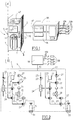
- the figure 1 shows, in a schematic perspective view with a cutaway at its lower part, a supply installation 1 of a working gas intended to supply one or more stations of consumption of these gases.
- This installation 1 comprises an insulation enclosure 3 in which are installed on the one hand, as can be seen in the figure thanks to the tearing, two bottles 5 and 7 of a pressurized working gas, and, d 'on the other hand, a device 9 for distributing the working gas, the pipes 11 and 13 of which respectively connected to the bottles 5 and 7 are visible in this figure.
- This installation 1 also comprises a door 3 'pivoting about a vertical axis (X) to allow the opening and closing of said enclosure 3.
- the installation 1 is connected by its outlet pipe 10 to a second working gas distribution device 9A serving to supply the working gas through its outlet pipes 10A to several consumption stations 10B at the same time.
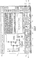
- the device 9 for distributing the working gas of the installation 1 comprises a set of pipes comprising in particular for each bottle 5 and 7 a main pipe 15 connected by means of a pipe 17 common to the outlet pipe 10 to convey the working gas to the consumption stations 10B, purge pipes 21 and gas extraction pipes 23 to obtain a partial vacuum in the chamber 3 by activating a vacuum generator 24.
- the latter comprises functional members 25 such as stop valves 27 and control valves 29 arranged in the various pipes 15, 17, 21 and 23, sensors 31 for measuring the pressures prevailing in particular in the main pipes 15, scales 33 for weighing the bottles 5 and 7 making it possible to determine the filling level of the bottles in the event that those they are filled with a liquefied gas, or else gas leak detectors 34, arranged in the enclosure 3 of the installation.
- functional members 25 such as stop valves 27 and control valves 29 arranged in the various pipes 15, 17, 21 and 23, sensors 31 for measuring the pressures prevailing in particular in the main pipes 15, scales 33 for weighing the bottles 5 and 7 making it possible to determine the filling level of the bottles in the event that those they are filled with a liquefied gas, or else gas leak detectors 34, arranged in the enclosure 3 of the installation.
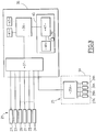
- control-command unit 35 of the functional members 25 comprises means 37 of communication with these functional members 25 and, connected to these means 37, means 39 for controlling various tasks relating to the functional organs 25, these tasks being stored in a task memory 41.
- Such tasks relate, for example, to the comparison of the measurement values read by the sensors 31 and I or by the scales 33 with predefined threshold values and stored in a threshold memory 43, the generation of an alarm signal if a of the measured values exceeds the associated threshold and, possibly, depending on the predefined priority level of the alarm, a partial or complete shutdown of the installation 1.
- the means 39 control via the communication means 37 the closing of certain valves of the installation.
- Another task concerns, for example, the control of the valves 27 and 29 when, for example, the bottle 5 supplying the device 9 is practically empty and the supply of the distribution device 9 must be switched over by the bottle 7 or vice versa.
- Yet another task relates to the detection of gas leaks by means of the detectors 34 and, in case of detection of such a leak, to the generation of an alarm signal and to a partial or complete shutdown of the gas. installation 1.
- a particular functional member 25 with which a special task is associated is formed by the second distribution device 9A of which only the control-command unit 35A and functional members 25A connected to this unit 35A are shown on the diagram. figure 3 .
- the structure of the device 9A is similar to that of the device 9 in that it also comprises a set of pipes, and functional members 25A such as valves 27A and 29A arranged in its pipes to regulate the flow of gas working, sensors 31A for measuring the pressures prevailing in the pipes and gas leak detectors 34A, the particular arrangement of the pipes and the valves will not be described in more detail.
- control-command unit 35A of the device 9A is identical to the control-command unit 35 of the distribution device 9.
- control unit 35A is connected to the communication means 37 of the unit 35.
- a special task controlled by the means 39 through the means 37 relates to the monitoring of the operating state of the device 9A.
- the pressure values measured by the intermediary of the sensors 31A and any leaks detected by the detectors 34A are transmitted to the control means 39.
- the various tasks can be controlled by the means 39 both in parallel and successively, or only on detection of an event such as for example the detection of an alarm.
- control-command unit 35 comprises means 45 for controlling the control means 39, allowing an operator, for example, to activate a task, or to choose and define certain parameters necessary for the control of a spot.
- control means 45 comprise a touch screen 47 and means 48 for memorizing diagrams or graphics intended to be displayed on the touch screen 47.
- the touch screen 47 is integrated into the outer wall of the upper part of the enclosure 3 of the installation 1 so that it is clearly visible and accessible for an operator responsible for monitoring the installation.
- the screen 47 is integrated in the door of the enclosure.
- the touch screen 47 is fixed on a box 47A integrated in the outer wall of the upper part of the enclosure 3 of the installation 1.
- the box is in the same plane as said door . Consequently, the operator stands in front of the installation 1 to read and access the touch screen 47.
- a connection device to link the information from the PLC (39) to the outside (maintenance tool, supervision, etc.) can be integrated. As well as a key to switch to maintenance mode.
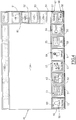
- FIG. 4 An example of a touch screen that can be used according to the present invention is shown in more detail at figure 4 .
- the touch screen 47 comprises at the bottom a first region 49 in which graphs 50, 51, 52, 53, 54, 55, 56, 57 and 58 are permanently displayed.
- Each graph 50 to 58 delimits on the touch screen 47 an associated main control zone, respectively bearing the reference numbers 60 to 68, that is to say zones by means of which an operator responsible for monitoring the installation 1 enters, by touching his finger on the touch screen 47, a command relating to a predetermined task in the control means 45.
- This first region 49 is strictly reserved for these main control areas 60 to 68 with the associated graphics 50 to 58, displayed permanently.
- These main control zones 60 to 68 are permanently receptive to receiving a command from the operator. This is particularly advantageous when the means 39 control different tasks in parallel, since the operator can access the control of a task by simply activating the main control zone associated with it.
- the touch screen 47 further comprises on its right, seen on the figure 4 , a second region 80 distinct from the first region 49, in which are displayed, depending on the activated task, graphics 81, 82, 83, and 84, represented in this figure only by frames.
- These graphics 81 to 84 delimit secondary control zones respectively bearing the reference numbers 91 to 94. These secondary control zones allow the operator to various operations relating to the specific task activated.
- control means further comprise signaling means 70, on the touch screen 47, of a main or secondary control zone activated by an operator.
- the signaling means 70 cause, following the activation of a control zone, for example the activation of the zone 60, the display on the touch screen 47 for example of a frame 72 in color surrounding the main activated control zone 60.
- the operator is always informed of the active task displayed on the screen.
- the touch screen 47 comprises at the top a third region 100, distinct from the first 49 and second 80 regions, which is reserved for the display of information relating to a main control zone, activated by the operator.
- the remainder of the touch screen 47, the region 104, which is surrounded by the regions 100, 80 and 49, is intended primarily for the display of information relating to the control of a task controlled by the means 39 when a main control zone associated with this task has been activated by the operator.
- the zone 104 is enlarged and further comprises the region 80.
- graph 50 shows a bell below which is marked "alarm”, and delimits the main control zone 60 relating to a task of management and display of alarms controlled by means 39 as has been described above .
- the activation of zone 60 by an operator causes the display in zone 104 of the touch screen 47 of the alarms detected, as shown in the figure. figure 5 .
- graphics 81 to 84 delimiting zones 91 to 94 of secondary commands relating to the management and display of alarms are displayed on the screen.
- the activation of the secondary zone 92 delimited by the graph 82 allows the display of an alarm history.
- Chart 51 of the figure 4 shows displays with numbers below which is marked "pressure”. This graph 51 delimits the main control zone 61 associated with the activation of a task relating to the reading of the pressure and weight values measured by the sensors 31 and the scales 33, and the display of these values on the touch screen 47 as shown on the figure 6 .
- Chart 52 of the figure 4 shows pipes and bottles connected to them below which is marked "synoptic". This graphic 52 delimits the main control zone 62 associated with the activation of a task relating to the reading of the measurement values measured by the sensors 31 and the scales 33 and to the display on the touch screen of a synoptic diagram. of the device, recorded in the storage means 48, together with the measured values recorded, as shown in the figure 7 .
- Chart 53 of the figure 4 shows a gas supply installation (a "gas cabinet") with cylinders and arrows indicating cylinder replacement, below which is marked "cylinders".
- This graphic 53 delimits the main control zone 63 associated with the activation of two tasks.
- One of these tasks relates to controlling the valves to perform purge cycles and necessary leak checks before and after each replacement of an empty cylinder with a full cylinder.
- the other task relates to the controls of the valves arranged in the pipes to ensure the switching of a supply of the distribution device 9 by one of the bottles 5 or 7 to a supply by the other bottle 7 or 5.
- An example of the screens displayed when zone 63 is activated is shown on the figure 8 .
- Chart 55 of the figure 4 shows pipes of a distribution device below which is marked "DD" (for distribution device).
- This graphic 55 delimits the main control zone 65 associated with the activation of a task relating to the evaluation of the measurement values recorded by the sensors 31A of the distribution device 9A arranged in series with the device 9 of the installation 1. , and the display on the touch screen of a diagram block diagram of the device 9A, recorded in the storage means 48, together with the measurement values recorded by the sensors 31A.
Landscapes
- Engineering & Computer Science (AREA)
- General Engineering & Computer Science (AREA)
- Mechanical Engineering (AREA)
- Theoretical Computer Science (AREA)
- Human Computer Interaction (AREA)
- Physics & Mathematics (AREA)
- General Physics & Mathematics (AREA)
- Filling Or Discharging Of Gas Storage Vessels (AREA)
- Testing And Monitoring For Control Systems (AREA)
Claims (13)
- Anlage zur Lieferung eines Arbeitsgases, die mit einem Isolationsgefäß (3) und einer um eine vertikale Achse (X) schwenkenden Tür (3') ausgestattet ist, um die Öffnung und der Schließung des Gefäßes (3) zu ermöglichen, umfassend mindestens eine Quelle (5, 7) eines Arbeitsdruckgases, die im Isolationsgefäß (3) angeordnet ist, und umfassend eine Ausgabevorrichtung (9) eines Arbeitsgases, umfassend eine Rohrleitungsanordnung (15, 21, 23), die mit mindestens einer Quelle (5, 7) von Arbeitsgas und mit mindestens einer Ausgangsrohrleitung (10, 10A) verbunden ist, um das Arbeitsgas zu einer Verbrauchsstelle (10B) zu leiten, Funktionsorgane (25, 25A), insbesondere Ventile (27, 29, 27A, 29A), die in den Rohrleitungen (15, 21, 23) angeordnet sind und dazu dienen, den Arbeitsgasstrom in diesen zu regeln, sowie Detektoren (34, 34A) von Gasaustritten, und eine Kontrollsteuereinheit (35, 35A), umfassend Mittel (37) zur Kommunikation mit den Funktionsorganen (35, 35A), Mittel (39) zur Kontrolle von Aufgaben, die sich auf die Funktionsorgane (25, 25A) beziehen, und Mittel (45) zum Lenken der Kontrollmittel (39), die von einem Betreiber der Ausgabevorrichtung (9, 9A) betätigt werden können, wobei die Lenkmittel (45) einen Berührungsbildschirm (47) umfassen, der Steuerzonen (60, 61, 62, 63, 64, 65, 66, 67, 68) aufweist, die mit der Kontrolle entsprechender Aufgaben assoziiert sind, dadurch gekennzeichnet, dass der Berührungsbildschirm an einem in der Tür (3') eingebauten Gehäuse (47A) befestigt ist, wobei das Gehäuse (47A) geeignet und gestaltet ist, um sich um eine vertikale Achse (Y) zu drehen.
- Anlage nach dem vorstehenden Anspruch, dadurch gekennzeichnet, dass der Berührungsbildschirm (47) Hauptsteuerzonen (60, 61, 62, 63, 64, 65, 66, 67, 68) aufweist, die mit der Kontrolle entsprechender Aufgaben assoziiert sind, wobei die Hauptsteuerzonen (60 bis 68) von Grafiken (50 bis 58) begrenzt sind, die mit den Aufgaben assoziiert sind.
- Anlage nach einem der vorstehenden Ansprüche, dadurch gekennzeichnet, dass der Berührungsbildschirm (47) für mindestens eine Hauptsteuerzone (60; 61; 62; 63; 64; 65; 66; 67; 68) mindestens eine Nebensteuerzone (91, 92, 93, 94) umfasst, die mit der mindestens einen Hauptzone (60; 61; 62; 63; 64; 65; 66; 67; 68) assoziiert ist und sich auf eine Anweisung zur Kontrolle der Aufgabe, die der mindestens einen Hauptsteuerzone (60; 61; 62; 63; 64; 65; 66; 67; 68) entspricht, bezieht, wobei die mindestens eine Nebensteuerzone (91, 92, 93, 94) von einer Grafik (81, 82, 83, 84) begrenzt ist, die mit der Anweisung assoziiert ist und auf dem Berührungsbildschirm (47) nur im Fall einer Aktivierung der entsprechenden Hauptsteuerzone (60; 61; 62; 63; 64; 65; 66; 67; 68) durch einen Betreiber angezeigt wird.
- Anlage nach einem der vorstehenden Ansprüche, dadurch gekennzeichnet, dass der Berührungsbildschirm (47) einen ersten Bereich (49) umfasst, der ausschließlich für die Hauptsteuerzonen (60 bis 68) vorbehalten ist, und einen zweiten Bereich (80), der sich vom ersten Bereich (49) unterscheidet und für die Nebensteuerzonen (91, 92, 93, 94) vorgesehen ist.
- Anlage nach einem der vorstehenden Ansprüche, dadurch gekennzeichnet, dass der Berührungsbildschirm (47) weiter einen dritten Bereich (100) umfasst, der sich vom ersten (49) und zweiten Bereich (80) unterscheidet und zur Anzeige einer Information vorbehalten ist, die sich auf eine von einem Betreiber aktivierten Hauptsteuerzone (60; 61; 62; 63; 64; 65; 66; 67; 68) bezieht.
- Anlage nach einem der vorstehenden Ansprüche, dadurch gekennzeichnet, dass die Lenkmittel (45) weiter Signalisierungsmittel (70), auf dem Berührungsbildschirm (47), einer von einem Betreiber aktivierten Steuerzone (60; 61; 62; 63; 64; 65; 66; 67; 68, 91, 92, 93, 94) umfassen.
- Anlage nach einem der vorstehenden Ansprüche, dadurch gekennzeichnet, dass eine von den Kontrollmitteln (39) kontrollierte Aufgabe sich auf die Verwaltung und insbesondere auf die Anzeige auf dem Berührungsbildschirm (47) der Alarme bezieht, die von den Funktionsorganen (25, 25A) erfasst werden, und dadurch, dass eine (60) der Hauptsteuerzonen des Berührungsbildschirms eine Aktivierungszone der Anzeige der erhobenen Alarme ist.
- Anlage nach einem der vorstehenden Ansprüche, mit Messsensoren (31), insbesondere von Drücken, die in den Rohrleitungen (15) herrschen, ausgestattet, dadurch gekennzeichnet, dass eine von den Kontrollmitteln (39) kontrollierte Aufgabe sich auf die Bewertung der von den Messsensoren (31) erhobenen Messwerte und auf die Anzeige dieser auf dem Berührungsbildschirm (47) bezieht, und dadurch, dass eine (61) der Hauptsteuerzonen eine Aktivierungszone der Anzeige der erhobenen Messwerte auf dem Bildschirm ist.
- Anlage nach einem der vorstehenden Ansprüche, mit Messsensoren (31), insbesondere von Drücken, die in den Rohrleitungen herrschen, ausgestattet, dadurch gekennzeichnet, dass die Lenkmittel (45) Speichermittel (48) eines Übersichtsschemas umfassen, das die Ausgabevorrichtung (9) des Arbeitsgases und die in dieser angeordneten Ventile (27, 29) darstellt, dadurch, dass eine von den Kontrollmitteln (39) kontrollierte Aufgabe sich auf die Bewertung der von den Messsensoren (31) erhobenen Messwerte und auf die gemeinsame Anzeige, auf dem Berührungsbildschirm (47) des Übersichtsschemas der Ausgabevorrichtung (9), das in den Speichermitteln (48) aufgezeichnet ist, und der von den Sensoren (31) erhobenen Messwerte bezieht, und dadurch, dass eine (62) der Hauptsteuerzonen eine Aktivierungszone der Anzeige des Übersichtsschemas mit den erhobenen Messwerten auf dem Berührungsbildschirm (47) ist.
- Anlage nach einem der vorstehenden Ansprüche, dadurch gekennzeichnet, dass sie zwei Quellen (5, 7) von Arbeitsgas umfasst, wobei die Quellen Gasflaschen sind.
- Anlage nach einem der vorstehenden Ansprüche, dadurch gekennzeichnet, dass die Lenkmittel (45) geeignet und gestaltet sind, um entfernt mithilfe einer WIFI-Verbindung mit einem Tablet, einem intelligenten Telefon oder einem tragbaren Computer mit einem Bildschirm, der mindestens die in den vorstehenden Ansprüchen definierten Zonen aufweist, gesteuert zu werden.
- Anlage nach einem der vorstehenden Ansprüche, dadurch gekennzeichnet, dass ein Nothalteknopf (B) am Gehäuse (47A) befestigt ist, wobei das Gehäuse ausgehend vom Boden auf einer Höhe von weniger als 1,70 m liegt.
- Anlage nach einem der vorstehenden Ansprüche, dadurch gekennzeichnet, dass die Größe des Berührungsbildschirms (47) kleiner als 12 Zoll, vorzugsweise kleiner als 6 Zoll ist.
Applications Claiming Priority (2)
| Application Number | Priority Date | Filing Date | Title |
|---|---|---|---|
| FR1557386A FR3039669B1 (fr) | 2015-07-31 | 2015-07-31 | Ecran tactile pivotant pour installation de distribution de gaz. |
| PCT/FR2016/051877 WO2017021616A1 (fr) | 2015-07-31 | 2016-07-20 | Ecran tactile pivotant pour installation de distribution de gaz |
Publications (2)
| Publication Number | Publication Date |
|---|---|
| EP3329175A1 EP3329175A1 (de) | 2018-06-06 |
| EP3329175B1 true EP3329175B1 (de) | 2020-09-23 |
Family
ID=54707903
Family Applications (1)
| Application Number | Title | Priority Date | Filing Date |
|---|---|---|---|
| EP16757286.6A Active EP3329175B1 (de) | 2015-07-31 | 2016-07-20 | Schwenkbarer berührungsbildschirm für eine gasverteilungsanlage |
Country Status (8)
| Country | Link |
|---|---|
| US (1) | US10823336B2 (de) |
| EP (1) | EP3329175B1 (de) |
| JP (1) | JP2018522183A (de) |
| KR (1) | KR20180053643A (de) |
| CN (1) | CN107850266A (de) |
| FR (1) | FR3039669B1 (de) |
| SG (1) | SG11201800719QA (de) |
| WO (1) | WO2017021616A1 (de) |
Families Citing this family (2)
| Publication number | Priority date | Publication date | Assignee | Title |
|---|---|---|---|---|
| US11255485B2 (en) * | 2017-12-13 | 2022-02-22 | J-W Power Company | System and method for priority CNG filling |
| CN112639352B (zh) * | 2018-09-03 | 2023-04-07 | 昭和电工株式会社 | 含氟气的气体的供给方法和供给设备 |
Family Cites Families (15)
| Publication number | Priority date | Publication date | Assignee | Title |
|---|---|---|---|---|
| GB2126054A (en) * | 1982-08-11 | 1984-03-14 | Philips Electronic Associated | Display system with nested information display |
| CA1279916C (en) * | 1987-02-12 | 1991-02-05 | Guy David | Gas cylinder monitor and control system |
| US5440477A (en) * | 1991-05-20 | 1995-08-08 | Creative Pathways, Inc. | Modular bottle-mounted gas management system |
| FR2772881B1 (fr) * | 1997-12-24 | 2000-01-14 | Alpes Systeme Automation | Dispositif de distribution d'un gaz de travail et installation de fourniture d'un gaz de travail equipee d'un tel dispositif |
| US6529123B1 (en) * | 1999-11-02 | 2003-03-04 | Rosen Products Llc | Automatically deployable and stowable display monitor |
| DE10106349C2 (de) * | 2001-02-09 | 2003-09-18 | Kendro Lab Prod Gmbh | Verfahren zur Befeuchtung eines Nutzraumes in einem Brutschrank sowie Begasungs-Brutschrank |
| JP2003029873A (ja) * | 2001-07-17 | 2003-01-31 | Hitachi Ltd | ラックマウントキャビネット |
| US20040037768A1 (en) * | 2001-11-26 | 2004-02-26 | Robert Jackson | Method and system for on-site generation and distribution of a process gas |
| US20080055491A1 (en) * | 2006-02-06 | 2008-03-06 | Spielo Manufacturing Ulc. | Cabinet with movable video screen |
| KR20120091036A (ko) * | 2009-10-02 | 2012-08-17 | 베에스하 보쉬 운트 지멘스 하우스게랫테 게엠베하 | 가전 기기용 도어 장치, 도어 장치를 포함하는 가전 기기 및, 가전 기기용 도어 장치의 작동 방법 |
| CN102809999A (zh) | 2011-06-03 | 2012-12-05 | 鸿富锦精密工业(深圳)有限公司 | 一种机柜 |
| US8917513B1 (en) * | 2012-07-30 | 2014-12-23 | Methode Electronics, Inc. | Data center equipment cabinet information center and updateable asset tracking system |
| US9562288B2 (en) * | 2013-04-24 | 2017-02-07 | Diamon Fusion International, Inc. | Defined dosing atmospheric temperature and pressure vapor deposition system |
| CN203375172U (zh) * | 2013-06-05 | 2014-01-01 | 四川金科环保科技有限公司 | 一种用于压缩天然气加气站的加气撬 |
| WO2014205366A1 (en) * | 2013-06-20 | 2014-12-24 | Nosocom Solutions, Inc. | Method and apparatus for medical accessories disinfection |
-
2015
- 2015-07-31 FR FR1557386A patent/FR3039669B1/fr not_active Expired - Fee Related
-
2016
- 2016-07-20 US US15/749,018 patent/US10823336B2/en active Active
- 2016-07-20 CN CN201680043566.XA patent/CN107850266A/zh active Pending
- 2016-07-20 EP EP16757286.6A patent/EP3329175B1/de active Active
- 2016-07-20 WO PCT/FR2016/051877 patent/WO2017021616A1/fr active Application Filing
- 2016-07-20 SG SG11201800719QA patent/SG11201800719QA/en unknown
- 2016-07-20 KR KR1020187004215A patent/KR20180053643A/ko not_active Application Discontinuation
- 2016-07-20 JP JP2018504288A patent/JP2018522183A/ja not_active Ceased
Non-Patent Citations (1)
| Title |
|---|
| None * |
Also Published As
| Publication number | Publication date |
|---|---|
| EP3329175A1 (de) | 2018-06-06 |
| FR3039669B1 (fr) | 2019-08-02 |
| FR3039669A1 (fr) | 2017-02-03 |
| JP2018522183A (ja) | 2018-08-09 |
| KR20180053643A (ko) | 2018-05-23 |
| WO2017021616A1 (fr) | 2017-02-09 |
| US10823336B2 (en) | 2020-11-03 |
| SG11201800719QA (en) | 2018-02-27 |
| CN107850266A (zh) | 2018-03-27 |
| US20180320825A1 (en) | 2018-11-08 |
Similar Documents
| Publication | Publication Date | Title |
|---|---|---|
| EP0926429A1 (de) | Arbeitsgasverteilungsvorrichtung und Arbeitsgasversorgungsanlage welche diese Vorrichtung verwendet | |
| EP3329175B1 (de) | Schwenkbarer berührungsbildschirm für eine gasverteilungsanlage | |
| US20100089486A1 (en) | Tanker Truck Monitoring System | |
| CA1256961A (fr) | Pressostat compense en temperature extincteur a securite de fonctionement equipe d'un tel pressostat et procede de remplissage d'un tel pressostat | |
| DK2020560T3 (en) | Electronic flow sensor | |
| RU2561841C2 (ru) | Противопожарная управляющая система | |
| MX2013001737A (es) | Controlador de sistema de maquina de chorro. | |
| EP0124405A1 (de) | Vorrichtung zur Abgabe eines Fluidums mit einem gegebenen Druck aus zwei Behältern an einer Leitung | |
| US11648431B2 (en) | Fire suppression system remote monitoring | |
| US11112062B2 (en) | Safety system for a pressure accumulator | |
| CA3094225A1 (en) | Fuel dispenser with leak detection | |
| KR20220032009A (ko) | 학습 모드가 있는 화재 감지 시스템 | |
| US20190322518A1 (en) | Dispensing apparatus and method of use thereof | |
| EP3384363B1 (de) | System zur steuerung der drucks eines versiegelten gehäuses | |
| CN112334198B (zh) | 灭火系统远程监测 | |
| KR102273840B1 (ko) | 무선 통신이 가능한 통합형 가스 절체기 | |
| KR20220027527A (ko) | 무선 통신이 가능한 일체형 가스 절체기 | |
| JPH0389100A (ja) | オートシリンダーボツクス | |
| FR2780485A1 (fr) | Dispositif de securite pour eviter le surremplissage des bouteilles de gaz liquefies, particulierement de gaz de petrole liquefies (gpl) | |
| FR2780484A1 (fr) | Dispositif de securite pour eviter le surremplissage des bouteilles de gaz liquefies, particulierement de gaz de petrole liquefies (gpl) | |
| JP2008304993A (ja) | 通信システム | |
| EP2969909A1 (de) | Mobile betankungsstation | |
| TWM621209U (zh) | 安裝於移動式壓力容器的氣流體計量設備 | |
| WO2023242694A1 (en) | Smart fire detection systems and methods | |
| JP2006242656A (ja) | 電子式ガスメータ |
Legal Events
| Date | Code | Title | Description |
|---|---|---|---|
| STAA | Information on the status of an ep patent application or granted ep patent |
Free format text: STATUS: THE INTERNATIONAL PUBLICATION HAS BEEN MADE |
|
| PUAI | Public reference made under article 153(3) epc to a published international application that has entered the european phase |
Free format text: ORIGINAL CODE: 0009012 |
|
| STAA | Information on the status of an ep patent application or granted ep patent |
Free format text: STATUS: REQUEST FOR EXAMINATION WAS MADE |
|
| 17P | Request for examination filed |
Effective date: 20180228 |
|
| AK | Designated contracting states |
Kind code of ref document: A1 Designated state(s): AL AT BE BG CH CY CZ DE DK EE ES FI FR GB GR HR HU IE IS IT LI LT LU LV MC MK MT NL NO PL PT RO RS SE SI SK SM TR |
|
| AX | Request for extension of the european patent |
Extension state: BA ME |
|
| DAV | Request for validation of the european patent (deleted) | ||
| DAX | Request for extension of the european patent (deleted) | ||
| GRAP | Despatch of communication of intention to grant a patent |
Free format text: ORIGINAL CODE: EPIDOSNIGR1 |
|
| STAA | Information on the status of an ep patent application or granted ep patent |
Free format text: STATUS: GRANT OF PATENT IS INTENDED |
|
| INTG | Intention to grant announced |
Effective date: 20200416 |
|
| GRAS | Grant fee paid |
Free format text: ORIGINAL CODE: EPIDOSNIGR3 |
|
| GRAA | (expected) grant |
Free format text: ORIGINAL CODE: 0009210 |
|
| STAA | Information on the status of an ep patent application or granted ep patent |
Free format text: STATUS: THE PATENT HAS BEEN GRANTED |
|
| AK | Designated contracting states |
Kind code of ref document: B1 Designated state(s): AL AT BE BG CH CY CZ DE DK EE ES FI FR GB GR HR HU IE IS IT LI LT LU LV MC MK MT NL NO PL PT RO RS SE SI SK SM TR |
|
| REG | Reference to a national code |
Ref country code: GB Ref legal event code: FG4D Free format text: NOT ENGLISH |
|
| REG | Reference to a national code |
Ref country code: CH Ref legal event code: EP |
|
| REG | Reference to a national code |
Ref country code: IE Ref legal event code: FG4D Free format text: LANGUAGE OF EP DOCUMENT: FRENCH |
|
| REG | Reference to a national code |
Ref country code: AT Ref legal event code: REF Ref document number: 1316734 Country of ref document: AT Kind code of ref document: T Effective date: 20201015 Ref country code: DE Ref legal event code: R096 Ref document number: 602016044554 Country of ref document: DE |
|
| REG | Reference to a national code |
Ref country code: CH Ref legal event code: NV Representative=s name: VALIPAT S.A. C/O BOVARD SA NEUCHATEL, CH |
|
| REG | Reference to a national code |
Ref country code: NL Ref legal event code: FP |
|
| PG25 | Lapsed in a contracting state [announced via postgrant information from national office to epo] |
Ref country code: GR Free format text: LAPSE BECAUSE OF FAILURE TO SUBMIT A TRANSLATION OF THE DESCRIPTION OR TO PAY THE FEE WITHIN THE PRESCRIBED TIME-LIMIT Effective date: 20201224 Ref country code: NO Free format text: LAPSE BECAUSE OF FAILURE TO SUBMIT A TRANSLATION OF THE DESCRIPTION OR TO PAY THE FEE WITHIN THE PRESCRIBED TIME-LIMIT Effective date: 20201223 Ref country code: FI Free format text: LAPSE BECAUSE OF FAILURE TO SUBMIT A TRANSLATION OF THE DESCRIPTION OR TO PAY THE FEE WITHIN THE PRESCRIBED TIME-LIMIT Effective date: 20200923 Ref country code: SE Free format text: LAPSE BECAUSE OF FAILURE TO SUBMIT A TRANSLATION OF THE DESCRIPTION OR TO PAY THE FEE WITHIN THE PRESCRIBED TIME-LIMIT Effective date: 20200923 Ref country code: BG Free format text: LAPSE BECAUSE OF FAILURE TO SUBMIT A TRANSLATION OF THE DESCRIPTION OR TO PAY THE FEE WITHIN THE PRESCRIBED TIME-LIMIT Effective date: 20201223 Ref country code: HR Free format text: LAPSE BECAUSE OF FAILURE TO SUBMIT A TRANSLATION OF THE DESCRIPTION OR TO PAY THE FEE WITHIN THE PRESCRIBED TIME-LIMIT Effective date: 20200923 |
|
| REG | Reference to a national code |
Ref country code: AT Ref legal event code: MK05 Ref document number: 1316734 Country of ref document: AT Kind code of ref document: T Effective date: 20200923 |
|
| PG25 | Lapsed in a contracting state [announced via postgrant information from national office to epo] |
Ref country code: RS Free format text: LAPSE BECAUSE OF FAILURE TO SUBMIT A TRANSLATION OF THE DESCRIPTION OR TO PAY THE FEE WITHIN THE PRESCRIBED TIME-LIMIT Effective date: 20200923 Ref country code: LV Free format text: LAPSE BECAUSE OF FAILURE TO SUBMIT A TRANSLATION OF THE DESCRIPTION OR TO PAY THE FEE WITHIN THE PRESCRIBED TIME-LIMIT Effective date: 20200923 |
|
| REG | Reference to a national code |
Ref country code: LT Ref legal event code: MG4D |
|
| PG25 | Lapsed in a contracting state [announced via postgrant information from national office to epo] |
Ref country code: LT Free format text: LAPSE BECAUSE OF FAILURE TO SUBMIT A TRANSLATION OF THE DESCRIPTION OR TO PAY THE FEE WITHIN THE PRESCRIBED TIME-LIMIT Effective date: 20200923 Ref country code: CZ Free format text: LAPSE BECAUSE OF FAILURE TO SUBMIT A TRANSLATION OF THE DESCRIPTION OR TO PAY THE FEE WITHIN THE PRESCRIBED TIME-LIMIT Effective date: 20200923 Ref country code: RO Free format text: LAPSE BECAUSE OF FAILURE TO SUBMIT A TRANSLATION OF THE DESCRIPTION OR TO PAY THE FEE WITHIN THE PRESCRIBED TIME-LIMIT Effective date: 20200923 Ref country code: PT Free format text: LAPSE BECAUSE OF FAILURE TO SUBMIT A TRANSLATION OF THE DESCRIPTION OR TO PAY THE FEE WITHIN THE PRESCRIBED TIME-LIMIT Effective date: 20210125 Ref country code: SM Free format text: LAPSE BECAUSE OF FAILURE TO SUBMIT A TRANSLATION OF THE DESCRIPTION OR TO PAY THE FEE WITHIN THE PRESCRIBED TIME-LIMIT Effective date: 20200923 Ref country code: EE Free format text: LAPSE BECAUSE OF FAILURE TO SUBMIT A TRANSLATION OF THE DESCRIPTION OR TO PAY THE FEE WITHIN THE PRESCRIBED TIME-LIMIT Effective date: 20200923 |
|
| PG25 | Lapsed in a contracting state [announced via postgrant information from national office to epo] |
Ref country code: ES Free format text: LAPSE BECAUSE OF FAILURE TO SUBMIT A TRANSLATION OF THE DESCRIPTION OR TO PAY THE FEE WITHIN THE PRESCRIBED TIME-LIMIT Effective date: 20200923 Ref country code: AL Free format text: LAPSE BECAUSE OF FAILURE TO SUBMIT A TRANSLATION OF THE DESCRIPTION OR TO PAY THE FEE WITHIN THE PRESCRIBED TIME-LIMIT Effective date: 20200923 Ref country code: AT Free format text: LAPSE BECAUSE OF FAILURE TO SUBMIT A TRANSLATION OF THE DESCRIPTION OR TO PAY THE FEE WITHIN THE PRESCRIBED TIME-LIMIT Effective date: 20200923 Ref country code: PL Free format text: LAPSE BECAUSE OF FAILURE TO SUBMIT A TRANSLATION OF THE DESCRIPTION OR TO PAY THE FEE WITHIN THE PRESCRIBED TIME-LIMIT Effective date: 20200923 Ref country code: IS Free format text: LAPSE BECAUSE OF FAILURE TO SUBMIT A TRANSLATION OF THE DESCRIPTION OR TO PAY THE FEE WITHIN THE PRESCRIBED TIME-LIMIT Effective date: 20210123 |
|
| REG | Reference to a national code |
Ref country code: DE Ref legal event code: R097 Ref document number: 602016044554 Country of ref document: DE |
|
| PG25 | Lapsed in a contracting state [announced via postgrant information from national office to epo] |
Ref country code: SK Free format text: LAPSE BECAUSE OF FAILURE TO SUBMIT A TRANSLATION OF THE DESCRIPTION OR TO PAY THE FEE WITHIN THE PRESCRIBED TIME-LIMIT Effective date: 20200923 |
|
| PLBE | No opposition filed within time limit |
Free format text: ORIGINAL CODE: 0009261 |
|
| STAA | Information on the status of an ep patent application or granted ep patent |
Free format text: STATUS: NO OPPOSITION FILED WITHIN TIME LIMIT |
|
| PG25 | Lapsed in a contracting state [announced via postgrant information from national office to epo] |
Ref country code: SI Free format text: LAPSE BECAUSE OF FAILURE TO SUBMIT A TRANSLATION OF THE DESCRIPTION OR TO PAY THE FEE WITHIN THE PRESCRIBED TIME-LIMIT Effective date: 20200923 Ref country code: DK Free format text: LAPSE BECAUSE OF FAILURE TO SUBMIT A TRANSLATION OF THE DESCRIPTION OR TO PAY THE FEE WITHIN THE PRESCRIBED TIME-LIMIT Effective date: 20200923 |
|
| 26N | No opposition filed |
Effective date: 20210624 |
|
| PG25 | Lapsed in a contracting state [announced via postgrant information from national office to epo] |
Ref country code: MC Free format text: LAPSE BECAUSE OF FAILURE TO SUBMIT A TRANSLATION OF THE DESCRIPTION OR TO PAY THE FEE WITHIN THE PRESCRIBED TIME-LIMIT Effective date: 20200923 |
|
| PG25 | Lapsed in a contracting state [announced via postgrant information from national office to epo] |
Ref country code: LU Free format text: LAPSE BECAUSE OF NON-PAYMENT OF DUE FEES Effective date: 20210720 |
|
| PG25 | Lapsed in a contracting state [announced via postgrant information from national office to epo] |
Ref country code: HU Free format text: LAPSE BECAUSE OF FAILURE TO SUBMIT A TRANSLATION OF THE DESCRIPTION OR TO PAY THE FEE WITHIN THE PRESCRIBED TIME-LIMIT; INVALID AB INITIO Effective date: 20160720 |
|
| PG25 | Lapsed in a contracting state [announced via postgrant information from national office to epo] |
Ref country code: CY Free format text: LAPSE BECAUSE OF FAILURE TO SUBMIT A TRANSLATION OF THE DESCRIPTION OR TO PAY THE FEE WITHIN THE PRESCRIBED TIME-LIMIT Effective date: 20200923 |
|
| PGFP | Annual fee paid to national office [announced via postgrant information from national office to epo] |
Ref country code: NL Payment date: 20230719 Year of fee payment: 8 |
|
| PGFP | Annual fee paid to national office [announced via postgrant information from national office to epo] |
Ref country code: IT Payment date: 20230720 Year of fee payment: 8 Ref country code: IE Payment date: 20230719 Year of fee payment: 8 Ref country code: GB Payment date: 20230721 Year of fee payment: 8 Ref country code: CH Payment date: 20230801 Year of fee payment: 8 |
|
| PGFP | Annual fee paid to national office [announced via postgrant information from national office to epo] |
Ref country code: FR Payment date: 20230726 Year of fee payment: 8 Ref country code: DE Payment date: 20230719 Year of fee payment: 8 Ref country code: BE Payment date: 20230719 Year of fee payment: 8 |
|
| PG25 | Lapsed in a contracting state [announced via postgrant information from national office to epo] |
Ref country code: MK Free format text: LAPSE BECAUSE OF FAILURE TO SUBMIT A TRANSLATION OF THE DESCRIPTION OR TO PAY THE FEE WITHIN THE PRESCRIBED TIME-LIMIT Effective date: 20200923 |