EP3329043B1 - Verbundsystem und verfahren zur bewehrung, insbesondere strukturen aus verstärktem beton oder mauerwerk mit härtbarer oder gehärteter matrix und textilem bewehrungsgitter - Google Patents
Verbundsystem und verfahren zur bewehrung, insbesondere strukturen aus verstärktem beton oder mauerwerk mit härtbarer oder gehärteter matrix und textilem bewehrungsgitter Download PDFInfo
- Publication number
- EP3329043B1 EP3329043B1 EP16760127.7A EP16760127A EP3329043B1 EP 3329043 B1 EP3329043 B1 EP 3329043B1 EP 16760127 A EP16760127 A EP 16760127A EP 3329043 B1 EP3329043 B1 EP 3329043B1
- Authority
- EP
- European Patent Office
- Prior art keywords
- les
- reinforcement
- matrix
- weft
- threads
- Prior art date
- Legal status (The legal status is an assumption and is not a legal conclusion. Google has not performed a legal analysis and makes no representation as to the accuracy of the status listed.)
- Active
Links
Images



Classifications
-
- C—CHEMISTRY; METALLURGY
- C04—CEMENTS; CONCRETE; ARTIFICIAL STONE; CERAMICS; REFRACTORIES
- C04B—LIME, MAGNESIA; SLAG; CEMENTS; COMPOSITIONS THEREOF, e.g. MORTARS, CONCRETE OR LIKE BUILDING MATERIALS; ARTIFICIAL STONE; CERAMICS; REFRACTORIES; TREATMENT OF NATURAL STONE
- C04B24/00—Use of organic materials as active ingredients for mortars, concrete or artificial stone, e.g. plasticisers
- C04B24/24—Macromolecular compounds
- C04B24/26—Macromolecular compounds obtained by reactions only involving carbon-to-carbon unsaturated bonds
- C04B24/2641—Polyacrylates; Polymethacrylates
-
- C—CHEMISTRY; METALLURGY
- C04—CEMENTS; CONCRETE; ARTIFICIAL STONE; CERAMICS; REFRACTORIES
- C04B—LIME, MAGNESIA; SLAG; CEMENTS; COMPOSITIONS THEREOF, e.g. MORTARS, CONCRETE OR LIKE BUILDING MATERIALS; ARTIFICIAL STONE; CERAMICS; REFRACTORIES; TREATMENT OF NATURAL STONE
- C04B24/00—Use of organic materials as active ingredients for mortars, concrete or artificial stone, e.g. plasticisers
- C04B24/24—Macromolecular compounds
- C04B24/26—Macromolecular compounds obtained by reactions only involving carbon-to-carbon unsaturated bonds
- C04B24/2611—Polyalkenes
-
- C—CHEMISTRY; METALLURGY
- C04—CEMENTS; CONCRETE; ARTIFICIAL STONE; CERAMICS; REFRACTORIES
- C04B—LIME, MAGNESIA; SLAG; CEMENTS; COMPOSITIONS THEREOF, e.g. MORTARS, CONCRETE OR LIKE BUILDING MATERIALS; ARTIFICIAL STONE; CERAMICS; REFRACTORIES; TREATMENT OF NATURAL STONE
- C04B24/00—Use of organic materials as active ingredients for mortars, concrete or artificial stone, e.g. plasticisers
- C04B24/24—Macromolecular compounds
- C04B24/26—Macromolecular compounds obtained by reactions only involving carbon-to-carbon unsaturated bonds
- C04B24/2623—Polyvinylalcohols; Polyvinylacetates
-
- C—CHEMISTRY; METALLURGY
- C04—CEMENTS; CONCRETE; ARTIFICIAL STONE; CERAMICS; REFRACTORIES
- C04B—LIME, MAGNESIA; SLAG; CEMENTS; COMPOSITIONS THEREOF, e.g. MORTARS, CONCRETE OR LIKE BUILDING MATERIALS; ARTIFICIAL STONE; CERAMICS; REFRACTORIES; TREATMENT OF NATURAL STONE
- C04B24/00—Use of organic materials as active ingredients for mortars, concrete or artificial stone, e.g. plasticisers
- C04B24/24—Macromolecular compounds
- C04B24/26—Macromolecular compounds obtained by reactions only involving carbon-to-carbon unsaturated bonds
- C04B24/2676—Polystyrenes
-
- D—TEXTILES; PAPER
- D03—WEAVING
- D03D—WOVEN FABRICS; METHODS OF WEAVING; LOOMS
- D03D15/00—Woven fabrics characterised by the material, structure or properties of the fibres, filaments, yarns, threads or other warp or weft elements used
- D03D15/40—Woven fabrics characterised by the material, structure or properties of the fibres, filaments, yarns, threads or other warp or weft elements used characterised by the structure of the yarns or threads
- D03D15/44—Woven fabrics characterised by the material, structure or properties of the fibres, filaments, yarns, threads or other warp or weft elements used characterised by the structure of the yarns or threads with specific cross-section or surface shape
- D03D15/46—Flat yarns, e.g. tapes or films
-
- D—TEXTILES; PAPER
- D03—WEAVING
- D03D—WOVEN FABRICS; METHODS OF WEAVING; LOOMS
- D03D19/00—Gauze or leno-woven fabrics
-
- E—FIXED CONSTRUCTIONS
- E04—BUILDING
- E04G—SCAFFOLDING; FORMS; SHUTTERING; BUILDING IMPLEMENTS OR AIDS, OR THEIR USE; HANDLING BUILDING MATERIALS ON THE SITE; REPAIRING, BREAKING-UP OR OTHER WORK ON EXISTING BUILDINGS
- E04G23/00—Working measures on existing buildings
- E04G23/02—Repairing, e.g. filling cracks; Restoring; Altering; Enlarging
-
- E—FIXED CONSTRUCTIONS
- E04—BUILDING
- E04G—SCAFFOLDING; FORMS; SHUTTERING; BUILDING IMPLEMENTS OR AIDS, OR THEIR USE; HANDLING BUILDING MATERIALS ON THE SITE; REPAIRING, BREAKING-UP OR OTHER WORK ON EXISTING BUILDINGS
- E04G23/00—Working measures on existing buildings
- E04G23/02—Repairing, e.g. filling cracks; Restoring; Altering; Enlarging
- E04G23/0218—Increasing or restoring the load-bearing capacity of building construction elements
-
- D—TEXTILES; PAPER
- D10—INDEXING SCHEME ASSOCIATED WITH SUBLASSES OF SECTION D, RELATING TO TEXTILES
- D10B—INDEXING SCHEME ASSOCIATED WITH SUBLASSES OF SECTION D, RELATING TO TEXTILES
- D10B2505/00—Industrial
- D10B2505/02—Reinforcing materials; Prepregs
-
- E—FIXED CONSTRUCTIONS
- E04—BUILDING
- E04G—SCAFFOLDING; FORMS; SHUTTERING; BUILDING IMPLEMENTS OR AIDS, OR THEIR USE; HANDLING BUILDING MATERIALS ON THE SITE; REPAIRING, BREAKING-UP OR OTHER WORK ON EXISTING BUILDINGS
- E04G23/00—Working measures on existing buildings
- E04G23/02—Repairing, e.g. filling cracks; Restoring; Altering; Enlarging
- E04G23/0218—Increasing or restoring the load-bearing capacity of building construction elements
- E04G2023/0251—Increasing or restoring the load-bearing capacity of building construction elements by using fiber reinforced plastic elements
Definitions
- the technical field of the invention is that of the consolidation, in particular, of reinforced concrete or masonry works, such as buildings, civil engineering constructions (bridges, tunnels, pipelines, etc.).
- the invention relates to a composite consolidation system, in particular for reinforced concrete or masonry works, comprising a hardenable or hardened matrix and a textile reinforcement grid, as well as these two elements taken as such.
- the invention also relates to a method of consolidating, in particular, reinforced concrete or masonry structures, as well as the composite structure obtained at the end of this method.
- Dry and wet formulations of the curable matrix which is preferably a hydraulic matrix, are also contemplated by the invention.
- Consolidated works particularly in reinforced concrete or masonry, also form an integral part of the invention.
- Reinforced concrete or masonry works are buildings that can be made of agglomerate, reinforced concrete or other, brick, pebble, cement, rendering, lath, millstone, rubble, mortar, concrete block, stone, rammed earth, plaster, concrete bricks. These buildings are subject to alterations caused by the stresses undergone and/or by climatic or environmental aggressions of any nature, including seismic, and/or possibly, by design and/or construction defects.
- a home may, for example, become premises for an industrial tertiary activity.
- Such a change may go hand in hand with a change in the constraints undergone by the building. This may involve, for example, an increase in the load that a floor can support.
- Some known reinforcement processes consist of bonding carbon fiber fabrics or strips to structural elements (floors, beams, walls, posts, tunnels, pipes). These fabrics or strips are impregnated with hardening resin (epoxy resin) and fixed to these structural elements. After hardening Rapid resin formation produces a carbon/resin fabric or lamella composite that increases the mechanical strength and ductility of the consolidated structure.
- hardening resin epoxy resin
- the European patent EP0994223B1 discloses a heat-treated fabric useful as a reinforcement for construction work, in which the warp is made of yarns whose fibers (12K 800 tex carbon yarns) have high moduli, a coefficient of elasticity under tension, greater than 10GPa and a tensile yield strength greater than 600MPa, and in which the weft is made of glass yarns (60 tex) coated with a thermo-adhesive polymer material (40 tex / hot melt polyamide) whose melting temperature is between 40 and 250°C. The amount of thermo-adhesive polymer material is between 10 and 300% by weight relative to the glass yarns.
- This fabric is applied to building structures by means of an impregnating resin.
- the surface of the building structure in question is coated with a layer of impregnation resin, the reinforcing fabric is included in this first layer, a second layer of impregnation resin is applied, reinforcing fabric is again included in this second layer on which a third layer of impregnation resin is applied.
- the European patent EP1245547B1 describes a cementitious mortar intended to be used for reinforcing building elements, in combination with synthetic fibre meshes (carbon, aramid, glass, polyethylene polyester or other fibre) with a mesh size of between 10 and 35 mm.
- the mortar comprises cement, a fluidizing copolymer resin, a thixotropic additive derived from cellulose such as methylhydroxyethylcellulose or methylcellulose, a fine filler for example based on quartz (500 microns), fly ash or marble powder and possibly silica, as well as other additives.
- EP1893793B1 proposes an improvement of the reinforcing meshes used in the means of consolidating construction elements, disclosed by EP1245547B1 This improvement consists in that the constituent fibers of said reinforcing meshes are poly [benz (1, 2-D: 5,4-D ') bisoxazole-2,6-diyl-1, 4-phenylene] fibers.
- KR101308513B1 discloses a grid according to the preamble of claim 1.
- This solution lies at least in part in the implementation of a textile reinforcement comprising a means of geometric and dimensional stabilization of the network.
- This particular binding network in accordance with the invention makes it possible to obtain, ultimately, a composite structure for consolidating works, in particular reinforced concrete or masonry, having the expected mechanical properties in terms of resistance and ductility, in terms of adhesion to the support to be consolidated and in terms of ease of implementation and storage.
- the invention relates to the following elements taken as such and independently of each other: the textile reinforcement grid according to claim 1 and the hardened matrix/grid composite structure affixed to the structure to be consolidated.
- the invention relates to a composite structure having an elastic tensile modulus MTE less than or equal to -in MPa and in increasing order of preference-100,000, 80,000, 70,000.
- the invention aims at the use of a composite structure having an elastic tensile modulus MTE less than or equal to - in MPa and in an increasing order of preference - 100,000, 80,000, 70,000, to increase the resistance to seismic loads of a reinforced concrete or masonry structure, said structure being obtained from a composite system for consolidating structures, comprising a hardenable or hardened matrix and a textile reinforcement grid, in which the grid comprises at least one layer formed of a reinforcement made up of flat warp threads and weft threads and has dimensional stability under stress of the meshes of the reinforcement, before the application of the grid to the structure to be consolidated.
- the invention also relates to a consolidation method according to claim 8 of a work where it consists in marouflage the grid according to the invention on the work with the matrix according to the invention, after having mixed said matrix with a liquid, preferably water, to obtain a hardenable wet matrix.
- the invention relates to a wet formulation comprising the matrix according to the invention, mixed with a liquid, preferably water; as well as to the process for preparing this wet formulation.
- the invention relates to the use according to claim 10 of a grid according to the invention for consolidating a structure, in particular reinforced concrete or masonry, by marouflage using a wet formulation according to the invention.
- any singular designates indifferently a singular or a plural.
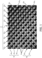
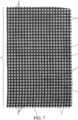
- Geometric regularity can also be assessed by a TR test defined below: The standard deviation in % relative to the mean of the surfaces of a random panel of 20 days of the reinforcement (in the attached figures, the reinforcement is designated by the reference 2 and the days or meshes of this reinforcement are designated by the reference 4 - Fig. 1 &7-) or a 20-day panel of the binding network (in the attached figures, the binding network is designated by the reference 3 and the days or meshes of this binding network are designated by the reference 5 - Fig.&7-), of a 40x40 cm grid sample is less than or equal to 15%, preferably 10%, and, even more preferably, 8%.
- This dimensional stability under stress of the grid and, advantageously the geometric regularity of this grid in particular just after its manufacture, or even after its packaging in a roll just after manufacture, guarantee its capacity not to deform and are ensured, in particular by the binding network of the reinforcement.
- dimensional stability under stress, or even geometric regularity are promoted by the coating of the grid, which makes it possible to "freeze” the assembly during the grid production process and ensures almost perfect dimensional stability of the grid during the stresses which may occur during the handling steps preceding its installation, as well as during the installation of the reinforcement.
- the number of crossings of the binding threads in each hole of the nonwoven reinforcement is less than or equal to 4, preferably less than or equal to 2 and more preferably still equal to 1.
- the holes of the reinforcement are not too obscured by the binding network.
- the grid comprises carbon in an amount (in g/m 2 ) included in the following intervals - in increasing order of preference -: [150- 500]; [170- 300]; [180-280]; [190-260]; [200-250].
- this grid as defined in the present description, the example and the figures, is preferably presented in the form of rolls or in the form of plates.
- the reinforcement is woven or non-woven, preferably non-woven.
- the weft threads and the warp threads of the reinforcement are included in two parallel planes.
- weft threads of the reinforcement are preferably arranged on the warp threads of this reinforcement, which warp threads form the face of the reinforcement intended to be placed in contact with the work to be consolidated.
- the filaments of a bundle may all be made from a single material, or may be made from different materials, each filament being made from a single material (e.g. filaments metal/filaments plant material -eg hemp-), or can even be made from a single material and/or different materials, each filament being made from several materials. All combinations are possible for the same bundle or for all or part.
- the warp threads and the weft threads of the reinforcement each consist of a bundle of filaments or fibers, preferably carbon, sized.
- filaments or fibers are not mechanically linked to each other, so that depending on the tension of the threads, their width and thickness can vary.
- the wires of the frame preferably carbon
- binding wires which form a network.
- the role of the binding wires is threefold. They allow to have a clean mesh geometry, a constant wire section and to obtain two layers of carbon wires superimposed and not entangled.
- the weave forming the binding network of the armature is of gauze pitch; each warp element of this weave comprising two binding threads, and each weft element of this weave comprising one binding thread.
- the leno weave is a weave in which the two warp threads cross around the weft thread, which provides excellent stability at the crossing points.
- the grid can be associated with a system for protecting against corrosion of the metal reinforcements of the concrete structure to be consolidated.
- These means can be metal wires coated with mixed metal oxides ("Mixed Metal Oxides - MMO-”), intended to form electrodes capable of allowing an electrochemical action against corrosion of the reinforcements of the reinforced concrete of the structure to be consolidated.
- These MMO metal wires could be binding wires.
- the binding threads are made of glass (type E). These binding threads have good tensile strength. They are selected in accordance with the invention, such that they do not break when they are put under tension at the time of weaving the grid. In addition, they are rot-proof and non-flammable.
- This configuration of 2 binding threads in the warp direction/1 binding thread in the weft direction with a tex equal to the sum of the tex of the other 2 threads makes it possible to avoid tensions in the rest of the reinforcement and to have regularity in the geometry of the stitches.
- the binding threads partly obstruct the meshes of the nonwoven reinforcement. It is therefore preferable for the binding threads to be as fine as possible, to limit the obstruction of these meshes and thus allow the matrix to pass through the grid. This optimizes the anchoring of the matrix in the grid and the mechanical characteristics of the matrix/grid system, particularly with regard to shear resistance.
- the hardenable matrix can be mineral and/or organic.
- a hardenable matrix preferably comprises one or more mineral and/or organic binders.
- the binder is at least partly made of cement.
- the binder is at least partly organic, chosen from the group comprising - ideally consisting of -: epoxy (co)polymers, (co)polyurethanes, and their mixtures.
- the D50 of these mineral fillers is less than or equal to 1000 ⁇ m; and, more advantageously, less than or equal to 800 or even 700 ⁇ m.
- Preferred examples include Vinylacetate-Ethylene copolymers.
- the matrix according to the invention comprises at least one of the following additives: a setting retarder, a setting accelerator, a water retainer, a water repellent, a colorant, fibers, an anti-foam, a rheological agent, an air-entraining agent or foaming agent, a gas-generating agent, a flame retardant.
- Setting retarders and complementary setting accelerators are products which modify the solubilities, dissolution and hydration rates of the various constituents of the dry cement composition.
- the water retainer has the property of retaining the mixing water before setting.
- the water is thus retained in the paste, mortar or concrete, which gives it very good adhesion and good hydration. To a certain extent, it is less absorbed on the support, the release on the surface is limited and there is thus little evaporation.
- the water repellent aims to reduce the penetration of water into the dry composition or the hardened product.
- Examples include sodium oleate or magnesium stearate.
- the colorant is intended to give the cured product the desired shade.
- examples include iron oxide Fe 2 0 3 or titanium dioxide Ti0 2 .
- the fibers aim to improve the mechanical resistance of the cured product.
- Antifoams are used to increase the cohesion of the mortar by limiting the presence of air bubbles. They reduce the side effect of other additives or consequent to mixing, causing air.
- antifoams we can cite polyether polyols.
- Rheological agents aim to modify the consistency of the wet product to adapt it to its application.
- examples include sepiolites, xanthan gums or silica fume.
- Foaming agents aim to provide additional porosity by entraining air during the mixing of the mineral binder.
- In situ gas generating agents aim to provide additional porosity by generating air in situ during mixing of the mineral binder.
- Flame retardants protect the cured product from fire.
- the invention also relates to the hardened composite structure obtained from the system according to the invention as defined in the description, the example and the figures.
- This hardened composite structure has a service temperature, which corresponds to the average temperature of a structural element, resulting from climatic temperatures in winter or summer and operating temperatures as defined by Standard NF EN 1991-1-5 in paragraph 5.2. This temperature can reach for example at least 80°C.
- the invention also relates to a composite structure having an elastic tensile modulus MTE less than or equal to - in MPa and in an increasing order of preference - 100,000, 80,000, 70,000, as well as the use of such a structure, to increase the resistance to seismic loads of a reinforced concrete or masonry structure, said structure being obtained from a composite system for consolidating structures, comprising a hardenable or hardened matrix and a textile reinforcement grid, in which the grid comprises at least one layer formed of a reinforcement made up of flat warp threads and weft threads and has dimensional stability under stress of the meshes of the reinforcement, before the application of the grid to the structure to be consolidated.
- the invention relates to the implementation of the system comprising the grid according to the invention and the cement matrix, to consolidate a structure, in particular of reinforced concrete or masonry, such as the wall of a building, a tunnel, a pipeline, a bridge pillar, etc.
- the hardenable wet matrix is advantageously sprayed onto the work, preferably by means of a pump, the grid is then positioned on the unhardened matrix and the marouflage is carried out, preferably using a smoothing machine, and possibly the matrix projection is renewed at least once, preferably by smoothing the surface of the matrix thus sprayed with the smoothing machine.
- the operations of projection, positioning of a new grid and marouflage are repeated n times, with n between 1 and 3; these operations can be carried out on the surface of the previously projected matrix which is not hardened or at least partly hardened.
- the wasting rates are for example between 10 and 30%.
- the grid according to the invention is implemented, ensuring that the chain direction of the grid is arranged in the axis of the constraint that we want to diffuse.
- a layer of mortar is applied to the area of the structure to be reinforced, either manually or mechanically, the grid is positioned and smoothed into the layer of mortar, for example using a smoother, then the composite system is finalized by applying a final layer (mechanical or manual application).
- This operation can preferably be repeated up to three times per superposition.
- the invention relates to a wet formulation for the building where it comprises the matrix according to the invention, mixed with a liquid, preferably water.
- the invention relates to a process for preparing the wet formulation according to the invention, where it essentially consists in mixing a liquid, preferably water, with all or part of the components of the matrix according to the invention, the remainder of the components then being gradually incorporated into the mixture if this has not been done previously.
- the invention relates to the use of a grid according to the invention to consolidate a structure, in particular reinforced concrete or masonry, by marouflage using a wet formulation according to the invention.
- the invention also relates to building or civil engineering works consolidated using the system according to the invention, after mixing with a liquid (preferably water) the matrix in the form of a dry composition in accordance with the invention, to obtain a wet formulation according to the invention, used to apply, at least once by marouflage, the grid according to the invention.
- a liquid preferably water
- the composite system for consolidating structures comprises a hardenable or hardened matrix and a textile reinforcement grid.
- the grid bears the reference 1 in the figures. It can be compared to a lattice composed of a non-woven reinforcement 2 and a network 3 for binding this reinforcement 2.
- the latter is made up of 2°c flat carbon warp threads which intertwine with 2°t flat carbon weft threads.
- the 3-weave network is a weave comprising 3°c warp elements and 3°t weft elements.
- the warp threads 2°c and the weft threads 2°t of the nonwoven reinforcement 2 are superimposed and perpendicular.
- the sheet formed by the warp threads 2°c can be described as lower because it is intended to be applied to the work to be consolidated, while the upper sheet is formed by the weft threads 2°t, which have by convention in the present disclosure a Face F1 and a Face F2 shown on the figure 3 .
- the warp threads 2°c are, in this example, simply placed on the weft threads 2°t. They are not secured to each other at their contact zones.
- the cohesion and geometric regularity of the reinforcement 2 are ensured, preferably only, by the binding network 3.
- a connection could be provided between the warp threads 2°c and the weft threads 2°t, at all or part of their contact zones, for example gluing and/or welding.
- the perpendicular arrangement of the warp threads 2°c and the weft threads 2°t is also a preference, but the angle between the warp and the weft could be different from 90°, for example between 30° and 120°, excluding 90°.
- warp yarns 2°c and weft yarns 2°t are preferably identical in this example, but it is not excluded to use warp yarns 2°c which are different from each other and/or weft yarns 2°t which are identical or different from each other.
- These reinforcement wires may correspond in particular to the carbon wires marketed by the company TORAY CARBON FIBERS EUROPE under the name FT300, T300, T300J, T400H, T700S, T700G, T800H, M35J, M40J, M46J, M55J, M60J, M30S, M40, T1000G, M50J, T600S, or T800S.
- the warp elements 3°c cross the weft threads 3°t of the binding network 3 in the holes 4 of the reinforcement 2, and thus also define regular holes 5 (cf. fig. 7 ).
- the warp elements 3°c are substantially perpendicular to the weft threads 3°t of the binding network 3.
- the warp elements 3°c of the binding network 3 are substantially parallel to the warp threads 2°c of the reinforcement and the weft elements 3°t of the binding network 3 are substantially parallel to the weft threads 2°t of the reinforcement 2.
- the carbon threads 2°t of the reinforcement 2 in the weft direction are immobilized by the binding network 3, which ensures geometric regularity of the whole.
- the weft elements 3°t of the binding network 3 could comprise, like the warp elements 3°c, two weft binding threads suitable for trapping the warp threads 2°c of the reinforcement 2. This further reinforces the cohesion, the resistance to deformation under stress and the regularity of the reinforcement 2.
- Each warp yarn 3i°c, 3ii°c and weft yarn 3°t is preferably made of a glass yarn.
- the count (in tex) of this warp glass binding yarn is 35 +/- 5
- the count (in tex) of the weft glass binding yarns is 75 +/- 5. This count of 38 tex in warp represents 51% of the count of 75 tex in weft.
- These glass binding wires may correspond to the products marketed by the company FULLTECH FIBER GLASS CORPORATION under the name ECG 75 1/0 0.7Z 172 SIZING (A-GRADE) and/or ECG 150 1/0 0.7Z 172 SIZING (A-GRADE).
- the grid according to the invention can be applied indifferently with the weft or warp threads in the axis of the stress to be distributed (diffused) (the carbon threads of the weft and the warp have an almost equivalent performance with regard to the recovery of force)
- the reinforcement can be applied to "take up” bending forces and so-called “sharp” forces.
- the grid 1 composed of the non-woven reinforcement 2 in threads 2°c, 2°t (e.g. carbon) reinforced by the binding network 3, is manufactured as indicated below for example using a loom, the production of the reinforcement 2 and the weaving on this reinforcement 2, of the threads 3i°c1, 3ii°c2 and 3°t (e.g. glass) according to a non-gauze weave of the binding network 3.
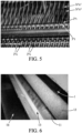
- FIG. 5 shows a detail of the loom, and in particular the warp binding threads 3i°c1, 3ii°c2, just after they cross, before they come to envelop a weft binding thread 3°t (not yet engaged in the loom and not appearing on the figure 5 ), to then cross again and then wrap a weft thread 2°t of the armature 2 (not yet engaged in the loom and not appearing on the figure 5 ).
- this type of binding induces a regular tension in the grid (warp and weft direction) which allows an equal distribution of the threads in all directions.
- the geometry of each day 4 of the reinforcement 2 or day 5 of the binding network 3 is very regular.
- the grid according to this embodiment example is coated by impregnation e.g. with a pure acrylic resin whose glass transition temperature is 25°C, the minimum film formation temperature is 14°C and whose dry extract is 46%.
- This coating/impregnation ensures and reinforces the dimensional stability of the assembly and the homogeneous distribution of stresses. This guarantees effective collaboration of all the filaments constituting the 2°c carbon threads of the chain of the reinforcement 2.
- the coating/impregnation acts as a "fixer” which allows the grid to effectively resist deformation. This allows a homogeneous distribution of stresses on the surface of the grid and in each carbon thread and facilitates their dissipation.
- the grid is preferably and as illustrated in this example, manufactured continuously, which allows efficient management of the tensions linked to manufacturing (loom).
- the wires are stretched evenly and constantly, then coated by dipping.
- FIG. 6 shows the uncoated grid 1b being circulated in the rollers 11, 12 of the coating machine, one of these rollers 11 being associated with a doctor blade, one of the edges of which parallel to the axis of the roller 11 is in contact with the grid 1, so as to form a receptacle containing a coating bath 13 which impregnates the grid 1 moving and which then passes between the coating roller 11 and the counter roller 12, so as to eliminate the excess coating liquid.
- the coated grid 1 is dried
- the grid is collected and packaged in a roll.
- the grid according to the invention can be applied indifferently with the weft or warp threads in the axis of the stress to be distributed (diffused).
- the carbon threads of the weft and the warp have an almost equivalent performance with regard to the absorption of force).
- the reinforcement can be applied to "absorb” bending forces and so-called “sharp” forces.
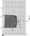
- This TS test consists of cutting a square sample E of grid of 40 ⁇ 40 cm from a roll of grid 1. This sample E is shown on the figure 4 .
- sample E is hung on a graduated board 15 by means of two hooks 16 on a horizontal bar 17, such that one of the hooks 16 is fixed at a distance of 2.5 cm (at the center distance of the attachment stud glued to the grid in the upper part) from one of the upper corners of sample E, and the other hook at a distance of 2.5 cm from the opposite upper corner (from the axis of the fixing hole to the outer edge of the grid).
- Each hook 16 consists of a threaded rod of diameter 6 mm, bent to form a hook.
- the bar is made from a metal profile in the shape of an upside-down "U” which is drilled in its base.
- the hook 16 is made integral with the "U” shaped bar because it passes through and is secured by a nut/lock nut system.
- sample E is aligned with the horizontal axis corresponding to the zero graduation of graduated table 15.
- the median day 4 is located in the lower terminal line of days 4 of sample E.
- This median day 4 is the one closest to the center of this lower terminal line sample E.
- a weight 20 of 1 kg or 2 kg is then attached to the centre of the sample E by means of a hook 18 comprising a curved terminal part 19 which is introduced into the median day 4.
- Hook 18 is made of a metal wire bent at both ends to form a double hook for securing sample E to the weight.
- the position of the lower edge of the sample E located just below the median day 4 or 5 is reported on the graduated table 15.
- the value V1 is read in cm, corresponding to the length between the zero graduation of the graduated table 15 and the position of the lower edge reported on the graduated table 15.
- cm D2 V2 - V0 in the case where the weight 20 is 2kg.
- V0 40 mm
- This TR test consists of cutting a square sample E of grid of 40x40 cm from a roll of grid 1 as obtained at the end of manufacture and which has therefore not been unrolled or handled. This sample E is shown on the figure 4 .
- the surface area is calculated on a random panel of 20 days of this sample.
- the length and width of each day are measured and finally the products of these 2 dimensions to obtain the surface area.
- the appropriate dimension measurements and calculations are carried out.
- the standard deviation of the reinforcement days area over a random panel of 20 days is calculated.
- the holes can be the holes or stitches 4 of the frame 2 or the holes or stitches 5 of the binding network 3.
- the mesh area is calculated as: side 1 ⁇ side 2
- test bodies 100 which are composed of a plate 101 of composite grid/matrix system (100 x 500 mm 2 ) as well as aluminum heels 102 (4 x 100 x 100 mm) glued (sandblasting + double epoxy glue gluing at the ends of the plate). These heels 102 are each connected by a junction 103 to the tensile testing machine.
- the carbon/glass grid system according to the invention implemented, comprises a single grid glued using the cement matrix.
- the thickness of the composite system, once hardened, is 3 mm.
- the test is carried out on a ZWICK universal tensile testing machine with a capacity of 5 tonnes. It is a monotonic static test associated with a load increase speed of 1 mm/min (until the specimen breaks).
- the instrumentation selected includes two LVDT displacement sensors ⁇ 20 mm which are arranged on both sides of the test piece in a centered manner (laterally and in height).
- a judiciously arranged force sensor makes it possible to obtain the evolution of the applied force.
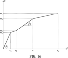
- figure 16 allows to identify the overall mechanical properties of the textile-mortar composites studied.
- the value E1 of the elastic tensile modulus MTE characterizes the composite structure according to the invention, in particular with regard to the resistance to seismic loads that the structure is able to provide to the works that it consolidates.
- Test tube 1 52000 2300 114 10.6 14.1 22.1 31.4 9400 Test tube 2 53100 2250 98 9.1 13.2 20.7 28.6 8780 Test tube 3 53000 2350 110 10.1 14.5 22.1 32 9650 Test tube 4 53150 2190 120 8.5 13.7 21 30.3 9250 Test tube 5 53150 2290 110 8.7 14.5 19.1 27.2 8100 Test tube 6 5 2 900 2300 100 8.4 12.9 18 27.9 8470 Average 52883.3 2280 108.67 8.93 13.8 20.5 29.4 8951.7 Standard deviation 443.47 54.4 8.36 1.02 0.67 1.65 2.21, 577.2 Characteristic value 51916.6 2161.4 90.45 6.71 12.35 16.9 24.5 7693.3
- the temperature resistance of the composite grid/matrix system according to the invention is evaluated by means of a double-lap tensile/shear test (parallel concrete blocks assembled on two symmetrical faces by the reinforcing materials).
- This test initially planned for polymer-based composites, particularly carbon-epoxy, is recommended by the working group of the French Civil Engineering Association (AFGC).
- AFGC French Civil Engineering Association
- the sizing of the specimens and the bonding surface are defined by seeking to minimize the effects of local constraints to allow exploitation under average stress.
- FIG 10 shows the concrete blocks 110 which have dimensions of 140mm*140mm*250mm (concrete prepared and implemented according to standard NF EN 18-422).
- the carbon/glass grid system according to the invention implemented comprises a single grid glued using the cement matrix.
- the thickness of the composite system, once hardened, is 3 mm.
- the reinforcement system is in the form of 2 strips 111 each having an anchoring length of 200 mm and a width of 50 mm.
- the strips 111 are arranged on 2 opposite faces of the 2 blocks 110 and connect them to each other while maintaining between their 2 facing end faces, a spacing ⁇ l.
- the distance (displacement) of the two blocks ( ⁇ l) is continuously recorded by displacement sensors 112 ( figure 10 ) LVDT type with stroke ⁇ 5mm accuracy 10-4mm and the changing speed is 1mm/min.
- test bodies used are the same as the test bodies 100 described above and shown in the figure 10 .
- the carbon/glass grid system according to the invention implemented, comprises a single grid glued using the cement matrix.
- the thickness of the composite system, once hardened, is 3mm.
- the test is carried out on a ZWICK universal tensile testing machine with a capacity of 5 tonnes and a load-increasing speed of 1 mm/min (until the specimen breaks).
- the instrumentation used includes two LVDT displacement sensors ⁇ 20 mm which are arranged on both sides of the specimen in a centred manner (laterally and in height). A judiciously arranged force sensor makes it possible to obtain the evolution of the applied force.
- the analysis of the results mainly consists of assessing the macroscopic damage to the specimen by taking as reference the evolution of the rigidity (ascending Young's modulus E+, descending Young's modulus E-, dissipated energy J, deformation per cycle, accumulated residual deformation, deformation at maximum stress) ( figure 11 ).
- the energy dissipated per cycle is significantly greater in the first cycle since it corresponds, to a large extent, to the formation of cracks. Beyond that, its evolution is almost constant for the following 999 cycles.
- the same mechanisms are mobilized (in stable proportions) from the second cycle and tend to suggest that the possible creation of additional cracks from the second cycle is non-existent or marginal. This last suggestion seems all the more realistic since it is supported by the evolution of the residual deformation which remains almost stable beyond the first cycle.
- the composite grid/matrix reinforcement system according to the invention is perfectly suited for beam repair with respect to bending stresses (bending moment).
- the concrete intended for making the slabs is defined by a compressive strength at 28 days of at least 30 MPa.
- the carbon/glass grid system according to the invention implemented comprises a single grid glued using the cement matrix. It is applied in a single layer to the surface of the latter. The thickness of the composite system, once hardened, is 3.0 mm ⁇ 0.2 mm. Then after coring, 6 metal pellets are glued using an epoxy mortar with a tensile strength greater than 10 MPa.
- the adhesion meter used is of the SATEC type ( figure 12 in which (120): outer ring - (121): metal pellets - (122): composite system - (123): concrete support). It allows a tensile force to be applied manually at a constant speed until rupture within 90 s.
- the average adhesion stress defined by the ratio of the average breaking load to the nominal surface area of the pellet.
- the latter equal to 2.1 MPa, is greater than 2 MPa.
- the observed failure is of the cohesive type, failure in the concrete of the substrate.
- a maximum breaking load of 12 tonnes is thus retained.
- the beam is deliberately damaged prior to the implementation of the composite grid/matrix system according to the invention and the plasticization of the tensioned reinforcements (residual deformation rate of the order of 350 ⁇ m/m) constitutes the damage criterion retained.
- FIG. 13 of beam P reinforced by a carbon/glass grid system according to the invention which comprises a single grid glued using the cement matrix and which is in the form of a strip 200 of width corresponding to the width of the beam, i.e. 150 mm, and of length equal to 195 cm, i.e. 5 cm less than the useful length of the beam tested, so as to avoid parasitic contact between the reinforcing element and the support.
- the thickness of the composite system, once hardened, is 3.0 mm ⁇ 0.15 mm.
- the load-deflection curves associated with the two beams from the same batch (the healthy reference beam and the damaged reinforced concrete beam P repaired using the grid/matrix reinforcement system according to the invention) ( figure 14 ) illustrate qualitatively similar behaviors although the initial stiffness of the beam reinforced by the composite grid/matrix system according to the invention, either lower due to its damage before repair.
- the slope of the beam P reinforced by the composite grid/matrix system according to the invention is slightly higher due to effective crack bridging. Then, a final non-linear zone is highlighted which reflects the progressive degradation of the beam (essentially of the steel reinforcements) and, where appropriate, of the added reinforcement. From a quantitative point of view, it is clear that the composite grid/matrix system according to the invention contributes to deferring the “inflection” point (called “plasticization threshold”) compared to the reference beam. Thus, an increase of the order of 20% is observed in terms of breaking load and an increase of the order of 10% is established in terms of plasticization load of the steel reinforcements.
- unit crack opening qualitatively very similar behaviors are also observed. However, the effect of the reinforcement of the composite grid/matrix system according to the invention is clearly highlighted. Indeed, the unit crack opening is reduced very significantly for an equivalent load level, and this up to high load levels corresponding to those envisaged at the SLS (Service Limit State) where the problems related to crack opening are central.
- SLS Service Limit State
- the useful length of the tested beams is 2 m.
- the thickness of the composite system, once cured, is 3.0 mm ⁇ 0.25 mm.
- the load-deflection curves obtained confirm the very good provisions of the composite grid/matrix system according to the invention for repair and/or reinforcement with respect to shear force ( figure 15 ).
- the composite grid/matrix system according to the invention contributes significantly to the increase in the ultimate load compared to the reference beam.
- the deviations range from roughly 15 to 20%, which is all the more satisfactory since only one layer of composite has been implemented.
- a zoom at the local scale makes it possible to highlight the ability of the composite grid/matrix system reinforcement according to the invention (independently of the configuration chosen) to generate a level of steel deformation very significantly higher than that of the reference beam.
- This parameter constitutes an indicator of the level of ductility of the structural element.
Landscapes
- Engineering & Computer Science (AREA)
- Chemical & Material Sciences (AREA)
- Architecture (AREA)
- Ceramic Engineering (AREA)
- Chemical Kinetics & Catalysis (AREA)
- Structural Engineering (AREA)
- Textile Engineering (AREA)
- Materials Engineering (AREA)
- Organic Chemistry (AREA)
- Electrochemistry (AREA)
- Civil Engineering (AREA)
- Mechanical Engineering (AREA)
- Working Measures On Existing Buildindgs (AREA)
- Woven Fabrics (AREA)
- Knitting Of Fabric (AREA)
- Treatments For Attaching Organic Compounds To Fibrous Goods (AREA)
Claims (10)
- Gitter zur Konsolidierung eines Bauwerks aus bewehrtem Beton oder Mauerwerk, das mindestens eine Schicht umfasst, die gebildet ist aus:- einerseits einer Bewehrung (2), die aus flachen Kettfäden (2°c) und Schussfäden (2°t) besteht;- und andererseits einem Bindenetzwerk (3) für die Bewehrung;
wobei das Bindenetzwerk so beschaffen ist, dass es die geometrische Regelmäßigkeit und die Maßhaltigkeit der Maschen der Bewehrung unter Belastung vor dem Aufbringen des Gitters auf das zu konsolidierende Bauwerk gewährleistet, wobei es sich bei dem Bindenetzwerk für die Bewehrung um eine Bindung handelt, die aus Kettelementen (3°c) und Schusselementen (3°t) besteht, und dadurch gekennzeichnet, dass es sich bei dieser Bindung um eine Dreherbindung handelt; wobei jedes Kettelement (3°c) dieser Bindung mindestens zwei Bindefäden (3i°c, 3ii°c), vorzugsweise zwei, umfasst und jedes Schusselement (3°t) dieser Bindung mindestens einen Bindefaden (3°t,3°t'), vorzugsweise einen, umfasst und dass:• jedes Kettelement (3°c) der Bindung zwei Kettbindefäden (3i°c, 3ii°c) umfasst und jedes Schusselement (3°t) der Bindung einen Schussbindefaden (3°t,3°t') umfasst,• einer der beiden Bindefäden an einer gleichen Seite C1 aller Schussfäden der Bewehrung verläuft,• der andere Kettbindefaden an einer C1 gegenüberliegenden gleichen Seite C2 aller Schussfäden der Bewehrung verläuft,• sich die Kettbindefäden (3i°c, 3ii°c) zwischen zwei aufeinanderfolgenden Schussfäden der Bewehrung vor dem Schussbindefaden (3°t,3°t') kreuzen, an beiden Seiten des Schussbindefadens verlaufen und sich dann wieder kreuzen, um den Schussfaden der Bewehrung zu umschlingen. - Verbundsystem zur Konsolidierung von Bauwerken, insbesondere aus bewehrtem Beton oder Mauerwerk, umfassend eine härtbare oder gehärtete Matrix und ein Gitter nach Anspruch 1.
- System nach Anspruch 2, dadurch gekennzeichnet, dass die Maßhaltigkeit unter Belastung wie folgt in einem TS-Test bestimmt wird:
Die Deformation einer 40 x 40 cm großen Probe, die an ihren beiden oberen Ecken in einer vertikalen Ebene aufgehängt und der Zugbelastung einer Masse von 1 (Deformation D1) oder 2 kg (Deformation D2), die in der Mitte des unteren Rands der Probe angehängt wird, unterworfen wird, ist so beschaffen, dass:• D1 kleiner oder gleich - in cm und in einer Reihenfolge zunehmender Bevorzugung - : 2,5; 1,5; 1,0; 0,8; 0,6; 0,5; 0,3; 0,2; 0,1 ist;• D2 kleiner oder gleich - in cm und in einer Reihenfolge zunehmender Bevorzugung - : 5; 4; 3; 2; 1,8; 1,6; 1,5; 1,4; 1,2; 1,0 ist. - System nach Anspruch 2 oder 3, dadurch gekennzeichnet, dass mindestens ein Teil der Fäden des Gitters mit mindestens einem Polymer bedeckt/imprägniert ist, welches vorzugsweise aus der Gruppe umfassend - oder noch besser bestehend aus -:• (Meth)acryl(co)polymeren, vorteilhafterweise ausgewählt aus der Untergruppe umfassend - oder noch besser bestehend aus - Copolymeren von Alkylestern mit vorteilhafterweise 1 bis 8 Kohlenstoffatomen mit Acrylsäure oder Methacrylsäure, insbesondere denjenigen aus der Familie umfassend - oder noch besser bestehend aus - vorzugsweise Methylacrylat, Ethylacrylat, Butylacrylat, 2-Ethylhexylacrylat und den Methacrylsäure-Pendants davon; und Mischungen davon;• Vinylester(co)polymeren, vorteilhafterweise ausgewählt aus der Untergruppe umfassend - oder noch besser bestehend aus - Homopolymeren und Copolymeren von Vinylacetat, insbesondere denjenigen aus der Familie umfassend - oder noch besser bestehend aus - Copolymeren von Vinylacetat und Ethylen, (Co)polymeren von Vinylchlorid wie Copolymeren von Vinylchlorid und Ethylen, (Co)polymeren von Vinyllaurat, (Co)polymeren von Vinylversatat, (Co)polymeren von Vinylestern von gesättigten oder ungesättigten, verzweigten oder unverzweigten alpha-Monocarbonsäuren mit vorteilhafterweise 9 oder 10 Kohlenstoffatomen, Homopolymeren von Vinylestern von gesättigten oder ungesättigten, verzweigten oder unverzweigten Alkylcarbonsäuren mit vorteilhafterweise 3 bis 8 Kohlenstoffatomen, Copolymeren dieser letzteren Homopolymere mit Ethylen, Vinylchlorid und/oder anderen Vinylestern; und Mischungen davon;• (Co)polymeren von Styrol mit Butadien oder mit einem oder mehreren Acrylsäureestern, vorteilhafterweise ausgewählt aus der Untergruppe umfassend - oder noch besser bestehend aus - ethylenisch ungesättigten Alkylestern mit vorteilhafterweise 1 bis 8 Kohlenstoffatomen von (Meth)acrylsäure, vorzugsweise Methylacrylat, Ethylacrylat, Butylacrylat, 2-Ethylhexylacrylat und den Methacrylsäure-Pendants davon; und Mischungen davon;• heißschmelzbaren (Co)polymeren, vorteilhafterweise ausgewählt aus der Untergruppe umfassend - oder noch besser bestehend aus - Polyethylenen, Polypropylenen, Polyestern, Polyamiden, Ethylen-Propylen-Dienmonomer(EPDM)-Copolymeren und Mischungen davon;• und Mischungen davon• ausgewählt ist.
- System nach mindestens einem der Ansprüche 2 bis 4, dadurch gekennzeichnet, dass die Schussfäden und die Kettfäden der Bewehrung in zwei parallelen Ebenen enthalten sind.
- System nach mindestens einem der Ansprüche 2 bis 5, dadurch gekennzeichnet, dass die härtbare Matrix Folgendes umfasst (in Gewichtsteilen auf Trockenbasis):∘ 100 Bindemittel;∘ 1 - 4000 und in einer Reihenfolge zunehmender Bevorzugung 5 - 2000; 10 - 1000; 20 - 500 mineralische Füllstoffe;∘ 0,01 - 1000 und in einer Reihenfolge zunehmender Bevorzugung 0,05 - 800; 0,1 - 500; 0,5 - 200; 1 - 50 mindestens eines Harzes;∘ 0 - 500 Additive, und vorzugsweise 0,01 - 50.
- Gehärtete Verbundstruktur, erhalten aus dem System nach mindestens einem der Ansprüche 2 bis 6.
- Verfahren zur Konsolidierung eines Bauwerks aus bewehrtem Beton oder Mauerwerk, dadurch gekennzeichnet, dass es darin besteht, dass man das Gitter gemäß Anspruch 1 auf das Bauwerk mit der Matrix gemäß Anspruch 2 oder 6 nach dem Mischen der Matrix mit einer Flüssigkeit, vorzugsweise Wasser, zum Erhalt einer härtbaren feuchten Matrix aufzieht.
- Verfahren nach Anspruch 8, dadurch gekennzeichnet, dass die härtbare feuchte Matrix auf das Bauwerk aufgespritzt wird, vorzugsweise mit einer Pumpe, dann das Gitter auf der nicht gehärteten Matrix positioniert und das Aufziehen durchgeführt wird, vorzugsweise mit Hilfe einer Glättkelle, und gegebenenfalls erneut mindestens einmal Matrix aufgespritzt wird, vorzugsweise unter Glättung der Oberfläche der so aufgespritzten Matrix mit der Glättkelle.
- Verwendung eines Gitters nach Anspruch 1 oder eines in Anspruch 2 vorgesehenen Gitters zur Konsolidierung insbesondere eines Bauwerks aus bewehrtem Beton oder Mauerwerk durch Aufziehen mit Hilfe einer feuchten Formulierung, die die Matrix gemäß Anspruch 2 oder 6 in Abmischung mit einer Flüssigkeit, vorzugsweise Wasser, umfasst.
Applications Claiming Priority (2)
| Application Number | Priority Date | Filing Date | Title |
|---|---|---|---|
| FR1557336A FR3039577B1 (fr) | 2015-07-30 | 2015-07-30 | Systeme composite et procede de consolidation notamment d'ouvrages en beton arme ou de maconnerie matrice durcissable ou durcie et grille de renfort textile constituant ce systeme |
| PCT/FR2016/051991 WO2017017393A1 (fr) | 2015-07-30 | 2016-07-29 | Systeme composite et procede de consolidation notamment d'ouvrages en beton arme ou de maçonnerie matrice durcissable ou durcie et grille de renfort textile constituant ce systeme |
Publications (3)
| Publication Number | Publication Date |
|---|---|
| EP3329043A1 EP3329043A1 (de) | 2018-06-06 |
| EP3329043C0 EP3329043C0 (de) | 2025-03-05 |
| EP3329043B1 true EP3329043B1 (de) | 2025-03-05 |
Family
ID=54848685
Family Applications (1)
| Application Number | Title | Priority Date | Filing Date |
|---|---|---|---|
| EP16760127.7A Active EP3329043B1 (de) | 2015-07-30 | 2016-07-29 | Verbundsystem und verfahren zur bewehrung, insbesondere strukturen aus verstärktem beton oder mauerwerk mit härtbarer oder gehärteter matrix und textilem bewehrungsgitter |
Country Status (12)
| Country | Link |
|---|---|
| US (1) | US11168025B2 (de) |
| EP (1) | EP3329043B1 (de) |
| CN (1) | CN108350623B (de) |
| AR (1) | AR105529A1 (de) |
| CL (1) | CL2018000248A1 (de) |
| DE (1) | DE112016003442T5 (de) |
| ES (2) | ES2696427B1 (de) |
| FR (1) | FR3039577B1 (de) |
| GB (1) | GB2557756A (de) |
| PH (1) | PH12018500214B1 (de) |
| SG (1) | SG11201800691PA (de) |
| WO (1) | WO2017017393A1 (de) |
Families Citing this family (11)
| Publication number | Priority date | Publication date | Assignee | Title |
|---|---|---|---|---|
| CN106795720B (zh) * | 2014-10-03 | 2019-10-18 | 贝卡尔特公司 | 包括成组金属单丝和聚合物涂层的平行组件的砌体加强结构 |
| CN109138490A (zh) * | 2018-11-01 | 2019-01-04 | 河北工业大学 | 一种采用nsm-trc加固砌体结构的方法及其砌体 |
| WO2022015157A1 (en) | 2020-07-17 | 2022-01-20 | Crt Manufacturing Sdn. Bhd. | Reinforcement mesh and method for producing thereof |
| CN112341035B (zh) * | 2020-09-24 | 2022-02-11 | 鹤壁宝来化工科技有限公司 | 一种混凝土流变调节剂及其制备方法 |
| DE102021103937A1 (de) | 2021-02-19 | 2022-08-25 | Mustafa Hidir | Wärmedämmender Putz |
| USD992310S1 (en) * | 2022-04-25 | 2023-07-18 | Lili Wang | Chair cover |
| DE102023200860A1 (de) * | 2023-02-02 | 2024-08-08 | Franken Maxit Mauermörtel Gmbh & Co | Kombination für die Herstellung einer bewehrten Lagerfugenmörtelschicht eines bewehrten Mauerwerks, derartige Lagerfugenmörtelschicht, bewehrtes Mauerwerk mit einer derartigen Lagerfugenmörtelschicht sowie Verfahren zur Herstellung einer derartigen Lagerfugenmörtelschicht und eines bewehrten Mauerwerks |
| DE102023203726A1 (de) * | 2023-04-24 | 2024-10-24 | Sgl Carbon Se | Bewehrungseinheit |
| US12421361B2 (en) * | 2023-05-08 | 2025-09-23 | Monosol, Llc | Water-soluble film including metal salts |
| CN117160605B (zh) * | 2023-09-04 | 2025-03-18 | 广安北新建材有限公司 | 一种促凝剂智能化加工方法及系统 |
| CN119569398B (zh) * | 2025-01-24 | 2025-04-22 | 同源新质(西安)新材料有限公司 | 一种高延性水泥基复合材料及其制备方法 |
Citations (1)
| Publication number | Priority date | Publication date | Assignee | Title |
|---|---|---|---|---|
| EP0387968B1 (de) * | 1989-03-15 | 1993-06-30 | Kanebo Ltd. | Gittergewebe, Verfahren zu seiner Herstellung und mit ihm bewehrter, geformter anorganischer Gegenstand |
Family Cites Families (18)
| Publication number | Priority date | Publication date | Assignee | Title |
|---|---|---|---|---|
| US4320160A (en) * | 1979-08-21 | 1982-03-16 | Toray Industries, Inc. | Fabric structure for fiber reinforced plastics |
| GB8322645D0 (en) | 1983-08-23 | 1983-09-28 | Lambeg Ind Research Assn | Textile reinforced cement structure |
| EP0153374A1 (de) * | 1983-08-29 | 1985-09-04 | Newsell Pty. Limited | Lagersystem |
| DE4130146A1 (de) | 1991-09-11 | 1993-03-18 | Gerhard Prof Dr Sc Tech Kuehne | Hochfester dynamisch belastbarer verbundwerkstoff |
| DE19525508C2 (de) | 1994-08-16 | 1999-01-21 | Hochtief Ag Hoch Tiefbauten | Verfahren zur Verbesserung der Tragfähigkeit von Bauteilen aus Stahlbeton oder Mauerwerk |
| IT1302656B1 (it) | 1998-10-13 | 2000-09-29 | Lino Credali | Tessuto atto all'applicazione come rinforzo di opere edili |
| JP4228497B2 (ja) * | 2000-02-09 | 2009-02-25 | 東レ株式会社 | 補強用織物 |
| ITMI20010665A1 (it) | 2001-03-29 | 2002-09-29 | Ruredil Spa | Malta cementizia struttura e metodo per il rinforzo di manufatti edili |
| JP3846252B2 (ja) | 2001-10-16 | 2006-11-15 | 東レ株式会社 | 補強用織物 |
| NZ551566A (en) | 2004-06-15 | 2010-01-29 | Constr Res & Tech Gmbh | Providing freezing and thawing resistance to cementitious compositions |
| ITMI20052156A1 (it) | 2005-11-11 | 2007-05-12 | Ruredil Spa | Manufatto edile e metodo di rinforzo di una struttura edile |
| JP2008150725A (ja) | 2006-12-15 | 2008-07-03 | Toray Ind Inc | 補強用からみ織物および複合材料 |
| US8796163B2 (en) * | 2008-08-29 | 2014-08-05 | Ryo Okada | Multi layer fabrics for structural applications having woven and unidirectional portions and methods of fabricating same |
| IT1401321B1 (it) | 2010-08-10 | 2013-07-18 | Lenzi Egisto Spa | Uso di un materiale tessile come barriera antinfortunistica a protezione delle utenze di un qualisiasi tipo di manufatto edile, in occorrenza di eventuali danneggiamenti di elementi strutturale e non |
| PL2465982T3 (pl) * | 2010-12-15 | 2016-04-29 | Groz Beckert Kg | Tkanina do zastosowania w materiałach kompozytowych oraz sposób wytwarzania tkaniny oraz materiału kompozytowego |
| FR2972732B1 (fr) * | 2011-03-16 | 2013-03-15 | Mdb Texinov Sa | Armature de renfort d'elements a matrice minerale |
| WO2013020950A2 (de) | 2011-08-09 | 2013-02-14 | Bayer Intellectual Property Gmbh | Verfahren zur verstärkung eines gebäudeteils |
| KR101308513B1 (ko) * | 2013-05-09 | 2013-09-17 | (주)우암건설 | 격자형 섬유 메쉬와 화이버보강 무기계 시멘트 매트릭스를 이용하여 건축물 및 건설 구조물의 보수 및 내진 성능을 향상시키는 내진 보강공법 |
-
2015
- 2015-07-30 FR FR1557336A patent/FR3039577B1/fr not_active Expired - Fee Related
-
2016
- 2016-07-29 ES ES201890004A patent/ES2696427B1/es not_active Withdrawn - After Issue
- 2016-07-29 GB GB1801454.8A patent/GB2557756A/en not_active Withdrawn
- 2016-07-29 US US15/747,892 patent/US11168025B2/en active Active
- 2016-07-29 CN CN201680044349.2A patent/CN108350623B/zh active Active
- 2016-07-29 PH PH1/2018/500214A patent/PH12018500214B1/en unknown
- 2016-07-29 SG SG11201800691PA patent/SG11201800691PA/en unknown
- 2016-07-29 DE DE112016003442.3T patent/DE112016003442T5/de not_active Withdrawn
- 2016-07-29 ES ES16760127T patent/ES3022635T3/es active Active
- 2016-07-29 AR ARP160102313A patent/AR105529A1/es active IP Right Grant
- 2016-07-29 EP EP16760127.7A patent/EP3329043B1/de active Active
- 2016-07-29 WO PCT/FR2016/051991 patent/WO2017017393A1/fr not_active Ceased
-
2018
- 2018-01-26 CL CL2018000248A patent/CL2018000248A1/es unknown
Patent Citations (1)
| Publication number | Priority date | Publication date | Assignee | Title |
|---|---|---|---|---|
| EP0387968B1 (de) * | 1989-03-15 | 1993-06-30 | Kanebo Ltd. | Gittergewebe, Verfahren zu seiner Herstellung und mit ihm bewehrter, geformter anorganischer Gegenstand |
Also Published As
| Publication number | Publication date |
|---|---|
| US20180230050A1 (en) | 2018-08-16 |
| CL2018000248A1 (es) | 2018-05-11 |
| ES2696427R1 (es) | 2019-02-07 |
| PH12018500214B1 (en) | 2023-03-15 |
| WO2017017393A1 (fr) | 2017-02-02 |
| EP3329043C0 (de) | 2025-03-05 |
| CN108350623B (zh) | 2021-07-06 |
| ES3022635T3 (en) | 2025-05-28 |
| SG11201800691PA (en) | 2018-02-27 |
| DE112016003442T5 (de) | 2018-05-09 |
| GB2557756A (en) | 2018-06-27 |
| FR3039577A1 (fr) | 2017-02-03 |
| ES2696427A2 (es) | 2019-01-15 |
| ES2696427B1 (es) | 2019-11-14 |
| CN108350623A (zh) | 2018-07-31 |
| GB201801454D0 (en) | 2018-03-14 |
| FR3039577B1 (fr) | 2022-09-02 |
| AR105529A1 (es) | 2017-10-11 |
| EP3329043A1 (de) | 2018-06-06 |
| PH12018500214A1 (en) | 2018-08-13 |
| US11168025B2 (en) | 2021-11-09 |
Similar Documents
| Publication | Publication Date | Title |
|---|---|---|
| EP3329043A1 (de) | Verbundsystem und verfahren zur bewehrung, insbesondere strukturen aus verstärktem beton oder mauerwerk mit härtbarer oder gehärteter matrix und textilem bewehrungsgitter | |
| JP4368796B2 (ja) | 無機マトリックス布装置及び方法 | |
| DE60102765T2 (de) | Mit Partikeln beschichtete Bindungssysteme zum Giessen hydratisierbarer Zementzusammensetzungen und Verfahren zur Darstellung solcher Bindungssysteme | |
| CN103964795B (zh) | 一种纤维编织网增强水泥基复合材料及其制备方法 | |
| NO304933B1 (no) | Syntetiske fiberbunter og fremgangsmÕte for fremstilling av et sementbasert materiale | |
| WO2019214187A1 (zh) | 一种提高多叶砖砌体墙抗震性能的trc的加固方法 | |
| CN105948579B (zh) | 一种防水性ecc与碳纤维布复合加固材料及其使用方法 | |
| Ganesan et al. | Effect of hybrid fibers on tension stiffening of reinforced geopolymer concrete | |
| Cho et al. | Mechanical evaluation of 3D printable nano-silica incorporated fibre-reinforced lightweight foam concrete | |
| Teng et al. | Multi-material 3D concrete printing: Automated hybrid reinforcements using textile and strain-hardening cementitious composites | |
| Abdulrahman et al. | Pull-off and slant-shear tests for evaluating bond strength in polymer-modified cement mortar reinforced with polypropylene fibers | |
| Ma et al. | Bond and tensile properties of flax textile reinforced recycled aggregate concrete: Strategies for interfacial enhancement and corresponding mechanisms | |
| Tian et al. | The effect of adding basalt fiber on the workability and mechanical properties of PE-ECC | |
| Selsiadevi et al. | Earth building blocks reinforced with jute and banana fiber | |
| Sanchez et al. | Multi-scale performance of carbon microfiber reinforced cement-based composites exposed to a decalcifying environment | |
| JP2008255517A (ja) | 繊維シート及びそれを用いたはく落防止方法 | |
| Majhi et al. | Thermal performance of an alkali-activated paste for bonding fibre sheets with concrete | |
| JP4817304B2 (ja) | 繊維補強モルタル又は繊維補強コンクリート、及びそれを用いてなる法枠の施工方法 | |
| DE102010003726B4 (de) | Fußbodenuntergrund | |
| JP2003253891A (ja) | コンクリート構造物の補修方法 | |
| Prakash et al. | Partial replacement of fine aggregate in concrete using recycled plastic | |
| Vatin et al. | Enhancing the Impact Strength of Prepacked Aggregate Fibrous Concrete Using Asphalt-Coated Aggregates. Materials 2022, 15, 2598 | |
| Singh et al. | Flexural behavior of reinforced masonry beams with ECC as bed joint | |
| Belkhir et al. | Mechanical behaviour of Composites based on Diss and Aflfa fibres in different matrices | |
| Holčapek et al. | Bond properties of concrete beams strengthened by AR-glass textile and basalt textile reinforced concrete |
Legal Events
| Date | Code | Title | Description |
|---|---|---|---|
| STAA | Information on the status of an ep patent application or granted ep patent |
Free format text: STATUS: THE INTERNATIONAL PUBLICATION HAS BEEN MADE |
|
| PUAI | Public reference made under article 153(3) epc to a published international application that has entered the european phase |
Free format text: ORIGINAL CODE: 0009012 |
|
| STAA | Information on the status of an ep patent application or granted ep patent |
Free format text: STATUS: REQUEST FOR EXAMINATION WAS MADE |
|
| 17P | Request for examination filed |
Effective date: 20180213 |
|
| AK | Designated contracting states |
Kind code of ref document: A1 Designated state(s): AL AT BE BG CH CY CZ DE DK EE ES FI FR GB GR HR HU IE IS IT LI LT LU LV MC MK MT NL NO PL PT RO RS SE SI SK SM TR |
|
| AX | Request for extension of the european patent |
Extension state: BA ME |
|
| DAV | Request for validation of the european patent (deleted) | ||
| DAX | Request for extension of the european patent (deleted) | ||
| RAP1 | Party data changed (applicant data changed or rights of an application transferred) |
Owner name: SIKA TECHNOLOGY AG |
|
| STAA | Information on the status of an ep patent application or granted ep patent |
Free format text: STATUS: EXAMINATION IS IN PROGRESS |
|
| 17Q | First examination report despatched |
Effective date: 20210827 |
|
| REG | Reference to a national code |
Ref country code: DE Ref legal event code: R079 Free format text: PREVIOUS MAIN CLASS: D03D0015000000 Ipc: D03D0015460000 Ref country code: DE Ref legal event code: R079 Ref document number: 602016091451 Country of ref document: DE Free format text: PREVIOUS MAIN CLASS: D03D0015000000 Ipc: D03D0015460000 |
|
| GRAP | Despatch of communication of intention to grant a patent |
Free format text: ORIGINAL CODE: EPIDOSNIGR1 |
|
| STAA | Information on the status of an ep patent application or granted ep patent |
Free format text: STATUS: GRANT OF PATENT IS INTENDED |
|
| RIC1 | Information provided on ipc code assigned before grant |
Ipc: E04G 23/02 20060101ALI20240906BHEP Ipc: D03D 19/00 20060101ALI20240906BHEP Ipc: D03D 15/46 20210101AFI20240906BHEP |
|
| INTG | Intention to grant announced |
Effective date: 20240927 |
|
| GRAS | Grant fee paid |
Free format text: ORIGINAL CODE: EPIDOSNIGR3 |
|
| GRAA | (expected) grant |
Free format text: ORIGINAL CODE: 0009210 |
|
| STAA | Information on the status of an ep patent application or granted ep patent |
Free format text: STATUS: THE PATENT HAS BEEN GRANTED |
|
| AK | Designated contracting states |
Kind code of ref document: B1 Designated state(s): AL AT BE BG CH CY CZ DE DK EE ES FI FR GB GR HR HU IE IS IT LI LT LU LV MC MK MT NL NO PL PT RO RS SE SI SK SM TR |
|
| REG | Reference to a national code |
Ref country code: GB Ref legal event code: FG4D Free format text: NOT ENGLISH |
|
| REG | Reference to a national code |
Ref country code: CH Ref legal event code: EP |
|
| REG | Reference to a national code |
Ref country code: IE Ref legal event code: FG4D Free format text: LANGUAGE OF EP DOCUMENT: FRENCH |
|
| REG | Reference to a national code |
Ref country code: DE Ref legal event code: R096 Ref document number: 602016091451 Country of ref document: DE |
|
| U01 | Request for unitary effect filed |
Effective date: 20250404 |
|
| U07 | Unitary effect registered |
Designated state(s): AT BE BG DE DK EE FI FR IT LT LU LV MT NL PT RO SE SI Effective date: 20250411 |
|
| REG | Reference to a national code |
Ref country code: ES Ref legal event code: FG2A Ref document number: 3022635 Country of ref document: ES Kind code of ref document: T3 Effective date: 20250528 |
|
| PG25 | Lapsed in a contracting state [announced via postgrant information from national office to epo] |
Ref country code: RS Free format text: LAPSE BECAUSE OF FAILURE TO SUBMIT A TRANSLATION OF THE DESCRIPTION OR TO PAY THE FEE WITHIN THE PRESCRIBED TIME-LIMIT Effective date: 20250605 |
|
| PGFP | Annual fee paid to national office [announced via postgrant information from national office to epo] |
Ref country code: GB Payment date: 20250619 Year of fee payment: 10 |
|
| PG25 | Lapsed in a contracting state [announced via postgrant information from national office to epo] |
Ref country code: NO Free format text: LAPSE BECAUSE OF FAILURE TO SUBMIT A TRANSLATION OF THE DESCRIPTION OR TO PAY THE FEE WITHIN THE PRESCRIBED TIME-LIMIT Effective date: 20250605 |
|
| PG25 | Lapsed in a contracting state [announced via postgrant information from national office to epo] |
Ref country code: HR Free format text: LAPSE BECAUSE OF FAILURE TO SUBMIT A TRANSLATION OF THE DESCRIPTION OR TO PAY THE FEE WITHIN THE PRESCRIBED TIME-LIMIT Effective date: 20250305 |
|
| PG25 | Lapsed in a contracting state [announced via postgrant information from national office to epo] |
Ref country code: GR Free format text: LAPSE BECAUSE OF FAILURE TO SUBMIT A TRANSLATION OF THE DESCRIPTION OR TO PAY THE FEE WITHIN THE PRESCRIBED TIME-LIMIT Effective date: 20250606 |
|
| U20 | Renewal fee for the european patent with unitary effect paid |
Year of fee payment: 10 Effective date: 20250731 |
|
| PG25 | Lapsed in a contracting state [announced via postgrant information from national office to epo] |
Ref country code: SM Free format text: LAPSE BECAUSE OF FAILURE TO SUBMIT A TRANSLATION OF THE DESCRIPTION OR TO PAY THE FEE WITHIN THE PRESCRIBED TIME-LIMIT Effective date: 20250305 |
|
| PGFP | Annual fee paid to national office [announced via postgrant information from national office to epo] |
Ref country code: ES Payment date: 20250801 Year of fee payment: 10 |
|
| PG25 | Lapsed in a contracting state [announced via postgrant information from national office to epo] |
Ref country code: PL Free format text: LAPSE BECAUSE OF FAILURE TO SUBMIT A TRANSLATION OF THE DESCRIPTION OR TO PAY THE FEE WITHIN THE PRESCRIBED TIME-LIMIT Effective date: 20250305 |
|
| PG25 | Lapsed in a contracting state [announced via postgrant information from national office to epo] |
Ref country code: CZ Free format text: LAPSE BECAUSE OF FAILURE TO SUBMIT A TRANSLATION OF THE DESCRIPTION OR TO PAY THE FEE WITHIN THE PRESCRIBED TIME-LIMIT Effective date: 20250305 |
|
| PG25 | Lapsed in a contracting state [announced via postgrant information from national office to epo] |
Ref country code: SK Free format text: LAPSE BECAUSE OF FAILURE TO SUBMIT A TRANSLATION OF THE DESCRIPTION OR TO PAY THE FEE WITHIN THE PRESCRIBED TIME-LIMIT Effective date: 20250305 |
|
| PG25 | Lapsed in a contracting state [announced via postgrant information from national office to epo] |
Ref country code: IS Free format text: LAPSE BECAUSE OF FAILURE TO SUBMIT A TRANSLATION OF THE DESCRIPTION OR TO PAY THE FEE WITHIN THE PRESCRIBED TIME-LIMIT Effective date: 20250705 |
|
| PLBE | No opposition filed within time limit |
Free format text: ORIGINAL CODE: 0009261 |
|
| STAA | Information on the status of an ep patent application or granted ep patent |
Free format text: STATUS: NO OPPOSITION FILED WITHIN TIME LIMIT |
|
| REG | Reference to a national code |
Ref country code: CH Ref legal event code: L10 Free format text: ST27 STATUS EVENT CODE: U-0-0-L10-L00 (AS PROVIDED BY THE NATIONAL OFFICE) Effective date: 20260114 |
|
| 26N | No opposition filed |
Effective date: 20251208 |
|
| REG | Reference to a national code |
Ref country code: CH Ref legal event code: H13 Free format text: ST27 STATUS EVENT CODE: U-0-0-H10-H13 (AS PROVIDED BY THE NATIONAL OFFICE) Effective date: 20260224 |
|
| PG25 | Lapsed in a contracting state [announced via postgrant information from national office to epo] |
Ref country code: CH Free format text: LAPSE BECAUSE OF NON-PAYMENT OF DUE FEES Effective date: 20250731 |