EP3327919B1 - Appareil onduleur - Google Patents
Appareil onduleur Download PDFInfo
- Publication number
- EP3327919B1 EP3327919B1 EP16827515.4A EP16827515A EP3327919B1 EP 3327919 B1 EP3327919 B1 EP 3327919B1 EP 16827515 A EP16827515 A EP 16827515A EP 3327919 B1 EP3327919 B1 EP 3327919B1
- Authority
- EP
- European Patent Office
- Prior art keywords
- reactor
- wiring board
- printed wiring
- power device
- connection portion
- Prior art date
- Legal status (The legal status is an assumption and is not a legal conclusion. Google has not performed a legal analysis and makes no representation as to the accuracy of the status listed.)
- Active
Links
- 238000001816 cooling Methods 0.000 claims description 37
- 230000001629 suppression Effects 0.000 claims description 2
- 239000003507 refrigerant Substances 0.000 description 39
- 239000003990 capacitor Substances 0.000 description 8
- 230000002093 peripheral effect Effects 0.000 description 7
- 239000007788 liquid Substances 0.000 description 6
- 238000010586 diagram Methods 0.000 description 4
- 239000010687 lubricating oil Substances 0.000 description 3
- 239000003921 oil Substances 0.000 description 3
- 238000007664 blowing Methods 0.000 description 2
- 238000002788 crimping Methods 0.000 description 2
- 239000012530 fluid Substances 0.000 description 2
- 238000009499 grossing Methods 0.000 description 2
- 238000010438 heat treatment Methods 0.000 description 2
- 239000000463 material Substances 0.000 description 2
- 238000005476 soldering Methods 0.000 description 2
- XAGFODPZIPBFFR-UHFFFAOYSA-N aluminium Chemical compound [Al] XAGFODPZIPBFFR-UHFFFAOYSA-N 0.000 description 1
- 229910052782 aluminium Inorganic materials 0.000 description 1
- 230000006835 compression Effects 0.000 description 1
- 238000007906 compression Methods 0.000 description 1
- 239000002826 coolant Substances 0.000 description 1
- 230000003247 decreasing effect Effects 0.000 description 1
- 230000000694 effects Effects 0.000 description 1
- 239000003822 epoxy resin Substances 0.000 description 1
- 239000011521 glass Substances 0.000 description 1
- 239000000203 mixture Substances 0.000 description 1
- 229920000647 polyepoxide Polymers 0.000 description 1
- 238000004904 shortening Methods 0.000 description 1
- 239000000758 substrate Substances 0.000 description 1
- 230000001360 synchronised effect Effects 0.000 description 1
- 229920003002 synthetic resin Polymers 0.000 description 1
- 239000000057 synthetic resin Substances 0.000 description 1
Images


Classifications
-
- F—MECHANICAL ENGINEERING; LIGHTING; HEATING; WEAPONS; BLASTING
- F24—HEATING; RANGES; VENTILATING
- F24F—AIR-CONDITIONING; AIR-HUMIDIFICATION; VENTILATION; USE OF AIR CURRENTS FOR SCREENING
- F24F1/00—Room units for air-conditioning, e.g. separate or self-contained units or units receiving primary air from a central station
- F24F1/06—Separate outdoor units, e.g. outdoor unit to be linked to a separate room comprising a compressor and a heat exchanger
- F24F1/20—Electric components for separate outdoor units
- F24F1/24—Cooling of electric components
-
- H—ELECTRICITY
- H02—GENERATION; CONVERSION OR DISTRIBUTION OF ELECTRIC POWER
- H02M—APPARATUS FOR CONVERSION BETWEEN AC AND AC, BETWEEN AC AND DC, OR BETWEEN DC AND DC, AND FOR USE WITH MAINS OR SIMILAR POWER SUPPLY SYSTEMS; CONVERSION OF DC OR AC INPUT POWER INTO SURGE OUTPUT POWER; CONTROL OR REGULATION THEREOF
- H02M7/00—Conversion of ac power input into dc power output; Conversion of dc power input into ac power output
- H02M7/003—Constructional details, e.g. physical layout, assembly, wiring or busbar connections
-
- F—MECHANICAL ENGINEERING; LIGHTING; HEATING; WEAPONS; BLASTING
- F25—REFRIGERATION OR COOLING; COMBINED HEATING AND REFRIGERATION SYSTEMS; HEAT PUMP SYSTEMS; MANUFACTURE OR STORAGE OF ICE; LIQUEFACTION SOLIDIFICATION OF GASES
- F25D—REFRIGERATORS; COLD ROOMS; ICE-BOXES; COOLING OR FREEZING APPARATUS NOT OTHERWISE PROVIDED FOR
- F25D23/00—General constructional features
- F25D23/003—General constructional features for cooling refrigerating machinery
-
- F—MECHANICAL ENGINEERING; LIGHTING; HEATING; WEAPONS; BLASTING
- F25—REFRIGERATION OR COOLING; COMBINED HEATING AND REFRIGERATION SYSTEMS; HEAT PUMP SYSTEMS; MANUFACTURE OR STORAGE OF ICE; LIQUEFACTION SOLIDIFICATION OF GASES
- F25D—REFRIGERATORS; COLD ROOMS; ICE-BOXES; COOLING OR FREEZING APPARATUS NOT OTHERWISE PROVIDED FOR
- F25D31/00—Other cooling or freezing apparatus
-
- H—ELECTRICITY
- H02—GENERATION; CONVERSION OR DISTRIBUTION OF ELECTRIC POWER
- H02M—APPARATUS FOR CONVERSION BETWEEN AC AND AC, BETWEEN AC AND DC, OR BETWEEN DC AND DC, AND FOR USE WITH MAINS OR SIMILAR POWER SUPPLY SYSTEMS; CONVERSION OF DC OR AC INPUT POWER INTO SURGE OUTPUT POWER; CONTROL OR REGULATION THEREOF
- H02M7/00—Conversion of ac power input into dc power output; Conversion of dc power input into ac power output
- H02M7/42—Conversion of dc power input into ac power output without possibility of reversal
- H02M7/44—Conversion of dc power input into ac power output without possibility of reversal by static converters
- H02M7/48—Conversion of dc power input into ac power output without possibility of reversal by static converters using discharge tubes with control electrode or semiconductor devices with control electrode
-
- H—ELECTRICITY
- H02—GENERATION; CONVERSION OR DISTRIBUTION OF ELECTRIC POWER
- H02P—CONTROL OR REGULATION OF ELECTRIC MOTORS, ELECTRIC GENERATORS OR DYNAMO-ELECTRIC CONVERTERS; CONTROLLING TRANSFORMERS, REACTORS OR CHOKE COILS
- H02P27/00—Arrangements or methods for the control of AC motors characterised by the kind of supply voltage
- H02P27/04—Arrangements or methods for the control of AC motors characterised by the kind of supply voltage using variable-frequency supply voltage, e.g. inverter or converter supply voltage
-
- H—ELECTRICITY
- H05—ELECTRIC TECHNIQUES NOT OTHERWISE PROVIDED FOR
- H05K—PRINTED CIRCUITS; CASINGS OR CONSTRUCTIONAL DETAILS OF ELECTRIC APPARATUS; MANUFACTURE OF ASSEMBLAGES OF ELECTRICAL COMPONENTS
- H05K1/00—Printed circuits
- H05K1/02—Details
- H05K1/0201—Thermal arrangements, e.g. for cooling, heating or preventing overheating
- H05K1/0203—Cooling of mounted components
-
- H—ELECTRICITY
- H01—ELECTRIC ELEMENTS
- H01L—SEMICONDUCTOR DEVICES NOT COVERED BY CLASS H10
- H01L23/00—Details of semiconductor or other solid state devices
- H01L23/34—Arrangements for cooling, heating, ventilating or temperature compensation ; Temperature sensing arrangements
- H01L23/46—Arrangements for cooling, heating, ventilating or temperature compensation ; Temperature sensing arrangements involving the transfer of heat by flowing fluids
- H01L23/473—Arrangements for cooling, heating, ventilating or temperature compensation ; Temperature sensing arrangements involving the transfer of heat by flowing fluids by flowing liquids
-
- H—ELECTRICITY
- H05—ELECTRIC TECHNIQUES NOT OTHERWISE PROVIDED FOR
- H05K—PRINTED CIRCUITS; CASINGS OR CONSTRUCTIONAL DETAILS OF ELECTRIC APPARATUS; MANUFACTURE OF ASSEMBLAGES OF ELECTRICAL COMPONENTS
- H05K7/00—Constructional details common to different types of electric apparatus
- H05K7/20—Modifications to facilitate cooling, ventilating, or heating
- H05K7/2089—Modifications to facilitate cooling, ventilating, or heating for power electronics, e.g. for inverters for controlling motor
Definitions
- the present invention relates to an inverter apparatus that controls an electric motor provided in a refrigerating device.
- an inverter apparatus described in Japanese Unexamined Patent Publication No. 2013-224785 includes a power device including a converter circuit and an inverter circuit, and a reactor provided in a DC power supply wire between the converter circuit and the inverter circuit to suppress harmonic.
- the power device is mounted on a printed wiring board, and the reactor is arranged at a position separated from the printed wiring board and connected to the printed wiring board by a harness (electric wire).
- the power device on the printed wiring board is cooled by a cooling jacket to which a refrigerant pipe is connected.
- US 6 650 559 B1 is concerned with reducing electrical noise. It uses a reactor to reduce the noise. The reactor is cooled through the cooler. The reactor is not in direct contact with the cooler, due to the intermediate noise reducing laminate on the printed circuit board.
- US 6 060 859 A teaches another motor driving circuit including an inverter driving an electric motor. It is concerned with achieving a sufficient DC voltage on the input side of the inverter.
- JP 2012 170183 A describes an intelligent power module (IPM) receiving power from a solar cell and provides it to a grid. The IPM containing a converter and an inverter, as well as a filter of reactors and capacitors. It is concerned with the power dissipation of the IMP and the reactors, which are attached to a heat sink having heat pipes conducting fluid.
- IPM intelligent power module
- the reactor is arranged at the position separated from the printed wiring board when seen in a plan view.
- size of an electric component box that houses the printed wiring board and the reactor is also increased, and restriction upon arranging the electric component box in the air conditioner is increased.
- the reactor is a so-called strong electric part, and a large electric current flows through the harness connecting the reactor and the printed wiring board. Therefore, a possibility that the harness serves as a noise propagation route and provides a harmful influence on peripheral electric parts (such as weak electric parts connected to the printed wiring board) is increased.
- An object of the present invention is to provide an inverter apparatus which can be more downsized, where an electric wire connecting a reactor and a printed wiring board can be shortened as far as possible, and the reactor can also be cooled.
- the present invention is an inverter apparatus that variably controls an operation frequency of an electric motor provided in a refrigerating device, including a printed wiring board, a power device attached to one surface of the printed wiring board, the power device including a converter circuit and an inverter circuit, a reactor arranged on a side of the one surface of the printed wiring board, at least a part of the reactor being arranged within a plane projection area of the printed wiring board, and a cooler for cooling the power device and the reactor, the cooler being arranged such that the power device and the reactor are interposed between the cooler and the printed wiring board.
- the reactor is directly attached to the side of the one surface of the printed wiring board.
- the reactor is in direct contact with the cooler.
- the inverter apparatus can be more downsized, and an electric wire connecting the reactor and the printed wiring board can be eliminated or shortened. Therefore, an influence of noises provided to peripheral electric parts by the electric wire can be reduced.
- the power device and the reactor can be arranged as close to each other as possible. Thus, not only the power device but also the reactor can be cooled by using the cooler.
- the entire reactor is arranged within the plane projection area of the printed wiring board.
- the inverter apparatus can be furthermore downsized.
- a connection terminal of the reactor is arranged within the plane projection area of the printed wiring board and directly connected to the printed wiring board.
- a connection terminal of the reactor may be arranged out of the plane projection area of the printed wiring board and connected to the printed wiring board via an electric wire.
- connection terminal of the reactor is arranged out of the plane projection area of the printed wiring board.
- a task for connecting the electric wire to the connection terminal such as arrangement of the electric wire can be easily performed.
- the reactor is a harmonic suppression reactor provided between the converter circuit and the inverter circuit in an electric circuit
- the printed wiring board includes a first connection portion to which the power device is connected, a second connection portion to which the reactor is connected, a third connection portion to which a power supply wire is connected, and a fourth connection portion to which an output wire to the electric motor is connected, and the first connection portion is arranged between the second connection portion, and the third connection portion and the fourth connection portion.
- an electric current from a power supply flows to the converter circuit, the reactor, and the inverter circuit in this order, and is outputted to the electric motor. Therefore, by arranging the connection portions as in the above configuration, wiring patterns in the printed wiring board can be formed along a flow of the electric current, so that the wiring patterns can be simplified.
- An object of the present invention is to provide the inverter apparatus which can be more downsized, where the electric wire connecting the reactor and the printed wiring board can be shortened as far as possible, and the reactor can also be cooled.
- FIG. 1 is a schematic configuration diagram of an air conditioner according to one embodiment of the present invention.
- An air conditioner 1 serving as a refrigerating device includes an outdoor unit 2 installed outdoor, and an indoor unit 3 installed indoor.
- the outdoor unit 2 and the indoor unit 3 are connected to each other by communication pipes.
- the air conditioner 1 includes a refrigerant circuit 4 that performs a vapor compression refrigerating cycle.
- An indoor heat exchanger 11, a compressor 12, an oil separator 13, an outdoor heat exchanger 14, an expansion valve (expansion mechanism) 15, an accumulator 16, a four way valve 17, and the like are provided in the refrigerant circuit 4.
- These are connected by a refrigerant pipe 10 through which a refrigerant of the refrigerant circuit 4 flows.
- the refrigerant pipe 10 includes a liquid pipe 10L and a gas pipe 10G.
- the indoor heat exchanger 11 is a heat exchanger for exchanging heat between the refrigerant and the indoor air, provided in the indoor unit 3.
- a cross fin type fin-tube heat exchanger or the like can be adopted as the indoor heat exchanger 11.
- an indoor fan (not shown) for blowing the indoor air to the indoor heat exchanger 11 is provided.
- the compressor 12, the oil separator 13, the outdoor heat exchanger 14, the expansion valve 15, the accumulator 16, and the four way valve 17 are provided in the outdoor unit 2.
- the compressor 12 compresses the refrigerant suctioned from a suction port and discharge the refrigerant from a discharge port.
- Various compressors such as a scroll compressor can be adopted as the compressor 12.
- the oil separator 13 separates lubricating oil from a mixture fluid of the lubricating oil and the refrigerant discharged from the compressor 12.
- the separated refrigerant is fed to the four way valve 17, and the lubricating oil is returned to the compressor 12.
- the outdoor heat exchanger 14 exchanges heat between the refrigerant and the outdoor air.
- a cross fin type fin-tube heat exchanger or the like can be adopted as the outdoor heat exchanger.
- an outdoor fan for blowing the outdoor air to the outdoor heat exchanger 14 is provided.
- the expansion valve 15 is arranged between the outdoor heat exchanger 14 and the indoor heat exchanger 11 in the refrigerant circuit 4.
- the expansion valve 15 expands the inflow refrigerant and decompress it to predetermined pressure.
- an electronic expansion valve 15 in which an opening degree is variable can be adopted as the expansion valve 15.
- the accumulator 16 separates the inflow refrigerant into a gas and a liquid, and is arranged between the suction port of the compressor 12 and the four way valve 17 in the refrigerant circuit 4.
- the gas refrigerant separated by the accumulator 16 is suctioned by the compressor 12.
- the four way valve 17 can be switched between a first state shown by a solid line and a second state shown by a broken line in FIG. 1 .
- the air conditioner 1 performs a cooling operation
- the four way valve 17 is switched into the first state.
- the air conditioner performs a heating operation
- the four way valve 17 is switched into the second state.
- a portion 10A of the refrigerant pipe 10 of the refrigerant circuit 4 is attached to a power device 41 of an inverter apparatus 21 and a refrigerant jacket (cooling plate) 44 for cooling a reactor 27 to be described later, and forms a cooler 20.
- the liquid side pipe among the refrigerant pipe 10 forms the cooler 20 as shown in FIG. 1 .
- the liquid side pipe forming the cooler 20 is the liquid side pipe between the outdoor heat exchanger 14 and the expansion valve 15 in the refrigerant circuit 4.
- the present invention is not limited to this.
- the refrigerant condensed in the outdoor heat exchanger 14 flows at the time of the cooling operation, and the refrigerant condensed in the indoor heat exchanger 11 and decompressed in the expansion valve 15 flows at the time of the heating operation.
- Temperatures of these refrigerants are different depending on an operation condition or the like, and, for example, about 40 to 45°C at the time of the cooling operation.
- FIG. 2 is a schematic configuration diagram of the inverter apparatus.
- This inverter apparatus 21 is used for variably controlling an operation frequency of a motor (electric motor) M that drives the compressor 12 or the fans in the air conditioner.
- the inverter apparatus 21 includes a converter circuit (rectification circuit) 22, a filter circuit 23, and an inverter circuit 24.
- the converter circuit 22 and the inverter circuit 24 form the power device 41 to be described later (refer to FIG. 3 ).
- the converter circuit 22 is connected to an AC power supply 31 and DC power supply wires 25, 26.
- the converter circuit 22 rectifies and converts AC voltage inputted from the AC power supply 31 into pulsating voltage, and outputs this to the DC power supply wires 25, 26.
- FIG. 2 shows a diode bridge as an example of the converter circuit 22.
- the present invention is not limited to this, and, for example, an AC-DC converter that converts AC voltage into DC voltage by synchronous rectification may be used.
- the AC power supply 31 may be a polyphase AC power supply or a monophase AC power supply.
- the filter circuit 23 is connected to the converter circuit 22 via the DC power supply wires 25, 26.
- the filter circuit 23 includes the reactor 27 and a capacitor 28.
- the reactor 27 is connected to the DC power supply wire 25.
- the reactor 27 suppresses harmonic superimposed on the DC voltage flowing through the DC power supply wire 25 mainly at the time of a normal action of the inverter circuit 24.
- the capacitor 28 is connected between an output side electric path of the reactor 27 and the DC power supply wire 26.
- the capacitor 28 forms a LC filter together with the reactor 27.
- This LC filter can damp a current component of a frequency which is the same as a frequency of a carrier used for generation of a control signal of the inverter circuit 24, and also suppress the current component of the frequency which is the same as the frequency of the carrier from flowing out to the AC power supply 31.
- the reactor 27 and the capacitor 28 in this example are used as the LC filter rather than forming a smoothing circuit.
- electrostatic capacitance of the capacitor 28 and inductance of the reactor 27 can be reduced, so that the capacitor 28 and the reactor 27 can be more downsized.
- a height difference between the power device 41 and the reactor can be decreased as described later (refer to FIG. 3 ), so that the reactor can be easily cooled by the cooler 20 together with the power device 41.
- the inverter circuit 24 is connected to the output side of the filter circuit 23 via the DC power supply wires 25, 26.
- the inverter circuit 24 is formed by plural switching elements (not shown) such as IGBTs. By properly controlling conduction/non-conduction of the switching elements, the inverter circuit 24 converts the DC voltage inputted via the filter circuit 23 into AC voltage and applies the voltage onto the motor M.
- the plural switching elements of the inverter circuit 24 are controlled by a control unit (not shown).
- FIG. 3 is a side view of a printed wiring board 42, the power device 41, and the reactor 27 forming the inverter apparatus 21.
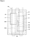
- FIG. 4 is a back view of the printed wiring board 42, the power device 41, and the reactor 27.
- the printed wiring board 42 wiring patterns made of a conductive body are formed on an insulating substrate of glass epoxy resin or the like formed into a rectangular shape in a plan view. Electric parts such as the capacitor 28, a resistor, a relay module, and a microcomputer are mounted on a main surface (upper surface) of the printed wiring board 42. Meanwhile, the power device 41 and the reactor 27 are arranged on a surface (back surface) opposite to the main surface of the printed wiring board 42.
- the power device 41 includes the converter circuit 22 and the inverter circuit 24 shown in FIG. 2 . In the power device 41 of the present embodiment, the converter circuit 22 and the inverter circuit 24 are housed in one case and modularized.
- the power device 41 is formed into a cuboid whose planar shape is a rectangle, the cuboid having thickness which is less than length of each side of the rectangle.
- the reactor 27 is similarly formed into a cuboid whose planar shape is a rectangle, the cuboid having thickness which is less than length of each side of the rectangle.
- the power device 41 and the reactor 27 are arranged side by side on the back surface side of the printed wiring board 42. Both the power device 41 and the reactor 27 are arranged within a plane projection area of the printed wiring board 42 adjacently to each other. Therefore, in comparison to a case where these parts 41, 27 (the reactor 27 in particular) are arranged out of the plane projection area of the printed wiring board 42, the inverter apparatus 21 can be more downsized.
- a large number of lead pins (connection terminals) 41a project in an outer peripheral portion of the power device 41. These lead pins 41a pass through the printed wiring board 42 in the up and down direction, and are connected to the wiring patterns of the printed wiring board 42.
- the reactor 27 includes a terminal block 27a in one side portion, and connection terminals 27b are provided in this terminal block 27a. Coil electric wires built in the reactor 27 are connected to the connection terminals 27b.
- the terminal block 27a is made of a synthetic resin material which is an insulating body. The terminal block 27a is arranged between the reactor 27 and the power device 41.
- the cooler 20 is arranged on lower surfaces of the power device 41 and the reactor 27 (surfaces opposite to the printed wiring board 42). This cooler 20 includes the cooling plate 44 and the refrigerant pipe 10A.
- the cooling plate 44 is made of a material having high thermal conductivity such as aluminum.
- the cooling plate 44 is provided in a range to cover the entire planar range of the power device 41 and the reactor 27.
- the cooling plate 44 includes a portion 44a that covers the lower surface side of the power device 41, and a portion 44b that covers the lower surface side of the reactor 27, and a step portion 44c is formed between both the portions 44a, 44b. Thickness of both the portions 44a, 44b is substantially the same, and a thickness difference between the power device 41 and the reactor 27 is absorbed by the step portion 44c.
- the portion 10A of the refrigerant pipe 10 is in contact with a lower surface of the cooling plate 44.
- this refrigerant pipe 10A is bent into a W shape to make two runs between one end portion of the cooling plate 44 and the other end portion. Since the refrigerant pipe 10 is bent into a W shape, substantially four straight pipe portions 10A1 of the refrigerant pipe 10A are arranged on the cooling plate 44, and two of the straight pipe portions 10A1 are arranged on the lower side of each of the power device 41 and the reactor 27.
- fixing plates 45 for fixing the refrigerant pipe 10A are provided in the cooling plate 44.
- Two fixing plates 45 are provided, and each of the fixing plates fixes two of the straight pipe portions 10A1.
- the refrigerant pipe 10A is fixed to the cooling plate 44 by being sandwiched between the cooling plate 44 and the fixing plates 45.
- the fixing plates 45 are attached to the cooling plate 44 by bolts and the like.
- the power device 41 and the reactor 27 are parts that generate more heat than the other parts on the printed wiring board 42 (high heat generating parts). However, both the power device and the reactor are cooled by performing heat exchange with the refrigerant flowing through the refrigerant pipe 10A via the cooling plate 44. Both the power device 41 and the reactor 27 are arranged on the one surface (back surface) side of the printed wiring board 42, and can be arranged close to each other. Thus, the power device and the reactor can be cooled by using the same cooler 20. Therefore, a structure for cooling the power device 41 and the reactor 27 can be simplified.
- the refrigerant pipe 10A is not limited to a W shape and may be bent into a U shape, for example.
- two straight pipe portions 10A1 of the U shaped refrigerant pipe 10A may be provided only in a portion 44a of the cooling plate 44 that covers the lower surface side of the power device 41. Even by only providing the straight pipe portions 10A1 in such a way, the reactor 27 can be sufficiently cooled.
- FIG. 5 is an illustrative plan view showing the wiring patterns of the printed wiring board.
- the printed wiring board 42 includes first connection portions C to H to which the power device 41 is connected, second connection portions I, J to which the reactor 27 is connected, third connection portions A to which a power supply wire 46 from the AC power supply 31 is connected, and fourth connection portions B to which an output wire 47 to the motor M is connected.
- the first connection portions C to H are provided at plural points corresponding to the plural lead pins 41a which are provided corresponding to the outer peripheral portion of the power device 41.
- the second connection portions I, J are provided at two points corresponding to two connection terminals 27b provided in the reactor 27.
- the third connection portions A are provided at three points corresponding to phases of the three-phase AC power supply 31.
- Each of the third connection portions A includes a terminal block 48 for attaching a crimping terminal in a terminal of the power supply wire 46 (refer to FIG. 2 ) by screwing or the like.
- the fourth connection portions B are provided at three points corresponding to output voltage of three phases outputted from the inverter circuit 24 of the power device 41.
- Each of the fourth connection portions B includes a terminal block 49 for attaching a crimping terminal in the output wire 47 connected to the motor M (refer to FIG. 2 ) by screwing or the like.
- the connection points of the third connection portions A and the fourth connection portions B are respectively provided in a place near the converter circuit 22 and the inverter circuit 24 in the power device 41. Thereby, the wiring patterns can be simplified.
- the first connection portions C to H connected to the power device 41 are arranged between the third connection portions A connected to the power supply wire 46 and the fourth connection portions B connected to the output wire 47, and the second connection portions I, J connected to the reactor 27.
- connection portions A and the first connection portions C among the first connection portions are connected by a wiring pattern 51 of the printed wiring board 42.
- the fourth connection portions B and the first connection portions D among the first connection portions are connected by a wiring pattern 52 of the printed wiring board 42.
- the second connection portion I among the second connection portions and the first connection portion G among the first connection portions are connected by a wiring pattern 53, and the second connection portion J and the first connection portion F are connected by a wiring pattern 54.
- an electric current flowing from the AC power supply 31 is inputted from the third connection portions A to the converter circuit 22 via the first connection portions C, then inputted from the converter circuit 22 to the reactor 27 via the first connection portion G and the second connection portion I, further inputted from the reactor 27 to the inverter circuit 24 via the second connection portion J and the first connection portion F, and outputted from the inverter circuit 24 to the motor M via the first connection portions D and the fourth connection portions B.
- the electric current from the AC power supply 31 flows to the converter circuit 22, the reactor 27, and the inverter circuit 24 in this order, and is outputted to the motor M.
- the wiring patterns 51 to 54 in the printed wiring board 42 can be formed along a flow of the electric current, so that the wiring patterns 51 to 54 can be simplified.
- connection terminals 27b of the reactor 27 are directly connected to the wiring patterns 53, 54 of the printed wiring board 42. Therefore, there is no electric wire for letting an electric current flow between the both. Thus, an influence of noises provided to peripheral electric parts due to the electric wire can be reduced.
- FIGS. 6A and 6B are illustrative sectional views each showing an example of connection between the connection terminals 27b of the reactor 27 and the printed wiring board 42.
- connection terminals 27b of the reactor 27 are inserted into holes 42a formed in the printed wiring board 42 and are fixed by soldering.
- connection terminals 27b of the reactor 27 are formed by press-fit pins.
- Each of the press-fit pins 27b has a hollow portion 27b1 in an intermediate portion in the longitudinal direction.
- connection terminals 27b may be fixed to the printed wiring board 42 by screwing or the like.
- the entire reactor 27 of the embodiment described above is arranged within the plane projection area of the printed wiring board 42. However, part of the reactor may be arranged within the plane projection area of the printed wiring board 42.
- the terminal block 27a in which the connection terminals 27b are provided among the reactor 27 is arranged out of the plane projection area of the printed wiring board 42, and the other portions are arranged within the plane projection area.
- the connection terminals 27b of the reactor 27 are connected to the second connection portions I, J of the printed wiring board 42 via harnesses (electric wires) 55.
- a half or more of the reactor 27 including the terminal block 27a is arranged out of the plane projection area of the printed wiring board 42.
- a half or more of the reactor 27 including the terminal block 27a is also arranged out of the plane projection area of the printed wiring board 42.
- the terminal block 27a is arranged in an end portion in the longitudinal direction of the reactor 27 in the example shown in FIG. 7B
- the terminal block 27a is arranged in an end portion in the short direction of the reactor 27 in the example shown in FIG. 7C and a distance between the terminal block 27a and the second connection portions I, J is shorter than the example shown in FIG. 7B . Therefore, the harnesses 55 connecting the terminal block 27a and the second connection portions I, J can be shortened.
- connection terminals 27b among the reactor 27 are arranged out of the plane projection area of the printed wiring board 42, the harnesses 55 for connecting to the second connection portions I, J can be connected outside the printed wiring board 42.
- a connection task such as arrangement of the harnesses 55 can be easily performed.
- the harnesses 55 connecting the connection terminals 27b of the reactor 27 and the printed wiring board 42 can be shortened.
- the harnesses 55 can be shortened as far as possible. There is a possibility that the harnesses 55 serve as noise propagation routes and provide the influence of noises on peripheral electric parts. Thus, by shortening the harnesses 55, the influence of noises can be reduced.
- FIG. 8 is a side view showing a modified example of the cooler 20.
- the cooler 20 of the embodiment described above cools the power device 41 and the reactor 27 with the refrigerant flowing through the refrigerant pipe 10A.
- the cooler 20 shown in FIG. 8 cools the power device 41 and the reactor 27 with the air as a cooling medium.
- Plural fins 44d for increasing a contact area with the air are provided on a lower surface of the cooling plate 44 of this cooler 20.
- the lower surface of the cooling plate 44 in which the fins 44d are provided is a flat surface, and on an upper surface of the cooling plate 44, a step surface 44e is provided between the portion 44a that covers the power device 41 and the portion 44b that covers the reactor 27, and thickness is different between both the portions 44a, 44b.
- a step surface 44e is provided between the portion 44a that covers the power device 41 and the portion 44b that covers the reactor 27, and thickness is different between both the portions 44a, 44b.
- the cooler 20 cools both the power device 41 and the reactor 27 by one cooling plate 44 in the above description.
- the cooling plate 44 may be divided into two corresponding to the power device 41 and the reactor 27.
- the present invention can also be applied to an inverter apparatus including a smoothing circuit in which pulsating voltage outputted from the converter circuit 22 is smoothed in place of the filter circuit 23 as described above.
- a large reactor 27 having greater inductance than that of the reactor of the filter circuit 23 is used. Even in such a case, the reactor 27 can also be cooled by the cooler 20 together with the power device 41.
- a cooling plate 44 having a structure in which the fins 44d are omitted from the cooling plate 44 shown in FIG. 8 may be used, or in the modified example shown in FIG. 8 , a cooling plate having a structure in which fins are provided in the cooling plate 44 shown in FIG. 2 may be used.
- the power device 41 is not limited to the power device in which the converter circuit 22 and the inverter circuit 24 are brought into an integrated module and may be a power device in which these circuits are formed as separate bodies.
- the printed wiring board 42, the power device 41 and the reactor 27, and the cooler 20 are arranged side by side in the up and down direction (laminated).
- the direction of arrangement of these is also not particularly limited.
- the printed wiring board 42, the power device 41 and the reactor 27, and the cooler 20 may be arranged and laminated in the horizontal direction.
- the present invention can also be applied to a refrigerating device other than the air conditioner 1 for indoor use.
Landscapes
- Engineering & Computer Science (AREA)
- Power Engineering (AREA)
- Chemical & Material Sciences (AREA)
- Combustion & Propulsion (AREA)
- Mechanical Engineering (AREA)
- General Engineering & Computer Science (AREA)
- Physics & Mathematics (AREA)
- Thermal Sciences (AREA)
- Microelectronics & Electronic Packaging (AREA)
- Inverter Devices (AREA)
Claims (4)
- Appareil onduleur qui commande de manière variable une fréquence de fonctionnement d'un moteur électrique (M) situé dans un dispositif de réfrigération (1), comprenant:une carte de circuit imprimé (42) ;un dispositif d'alimentation (41) fixé à une certaine surface de la carte de circuit imprimé (42), le dispositif d'alimentation incluant un circuit convertisseur (22) et un circuit onduleur (24) ;un réacteur (27) disposé sur un côté de la certaine surface de la carte de circuit imprimé (42), au moins une partie du réacteur étant agencée dans une zone de projection plane de la carte de circuit imprimé (42) ; etun refroidisseur (20) pour refroidir le dispositif d'alimentation (41) et le réacteur (27), le refroidisseur (20) étant agencé de telle sorte que le dispositif d'alimentation (41) et le réacteur (27) sont interposés entre le refroidisseur (20) et la carte de circuit imprimé (42) ;dans lequelle réacteur (27) est un réacteur de suppression harmonique prévu entre le circuit convertisseur (22) et le circuit onduleur (24) dans un circuit électrique,la carte de circuit imprimé (42) inclut une première portion de connexion (C à H) à laquelle est connecté le dispositif d'alimentation (41), une deuxième portion de connexion (I, J) à laquelle est connecté le réacteur (27), une troisième portion de connexion (A) à laquelle est connecté un fil d'alimentation électrique (46), et une quatrième portion de connexion (B) à laquelle est connecté un fil de sortie (47) vers le moteur électrique (M), etla première portion de connexion (C à H) est agencée entre la deuxième portion de connexion (I, J), et la troisième portion de connexion (A) et la quatrième portion de connexion (B).
- Appareil onduleur selon la revendication 1, dans lequel
le réacteur entier (27) est agencé dans la zone de projection plane de la carte de circuit imprimé (42). - Appareil onduleur selon la revendication 1 ou 2, dans lequel
une borne de connexion (27b) du réacteur (27) est agencée dans la zone de projection plane de la carte de circuit imprimé (42) et directement connectée à la carte de circuit imprimé (42). - Appareil onduleur selon la revendication 1, dans lequel
une borne de connexion (27b) du réacteur (27) est agencée en dehors de la zone de projection plane de la carte de circuit imprimé (42) et connectée à la carte de circuit imprimé (42) via un fil électrique (55).
Applications Claiming Priority (2)
| Application Number | Priority Date | Filing Date | Title |
|---|---|---|---|
| JP2015143853A JP6701637B2 (ja) | 2015-07-21 | 2015-07-21 | インバータ装置 |
| PCT/JP2016/066757 WO2017013951A1 (fr) | 2015-07-21 | 2016-06-06 | Appareil onduleur |
Publications (3)
| Publication Number | Publication Date |
|---|---|
| EP3327919A1 EP3327919A1 (fr) | 2018-05-30 |
| EP3327919A4 EP3327919A4 (fr) | 2019-03-20 |
| EP3327919B1 true EP3327919B1 (fr) | 2021-07-21 |
Family
ID=57833893
Family Applications (1)
| Application Number | Title | Priority Date | Filing Date |
|---|---|---|---|
| EP16827515.4A Active EP3327919B1 (fr) | 2015-07-21 | 2016-06-06 | Appareil onduleur |
Country Status (6)
| Country | Link |
|---|---|
| US (1) | US10495327B2 (fr) |
| EP (1) | EP3327919B1 (fr) |
| JP (1) | JP6701637B2 (fr) |
| CN (1) | CN107852103B (fr) |
| BR (1) | BR112017027856B1 (fr) |
| WO (1) | WO2017013951A1 (fr) |
Families Citing this family (15)
| Publication number | Priority date | Publication date | Assignee | Title |
|---|---|---|---|---|
| GB2542353A (en) * | 2015-09-15 | 2017-03-22 | Alstom Technology Ltd | A busbar assembly |
| JP6639689B2 (ja) * | 2016-09-16 | 2020-02-05 | 三菱電機株式会社 | 冷凍サイクル装置 |
| JP6884007B2 (ja) * | 2017-02-28 | 2021-06-09 | 日立ジョンソンコントロールズ空調株式会社 | 電力変換装置、及びこれを備える機器 |
| JP6828516B2 (ja) * | 2017-03-02 | 2021-02-10 | ダイキン工業株式会社 | 電力変換装置 |
| WO2019008634A1 (fr) * | 2017-07-03 | 2019-01-10 | 三菱電機株式会社 | Dissipateur thermique |
| JP2019022344A (ja) * | 2017-07-18 | 2019-02-07 | ダイキン工業株式会社 | アクティブフィルタシステム、空気調和装置 |
| CN107493672B (zh) * | 2017-08-04 | 2019-07-30 | 广东美的制冷设备有限公司 | 电控板及制冷装置 |
| GB2580262B (en) * | 2017-10-26 | 2022-09-14 | Mitsubishi Electric Corp | Heat sink and circuit device |
| US10557638B2 (en) | 2017-11-21 | 2020-02-11 | Haier Us Appliance Solutions, Inc. | Fan assembly for a packaged terminal air conditioner unit |
| US20200221611A1 (en) * | 2017-11-30 | 2020-07-09 | Mitsubishi Electric Corporation | Power conversion device and air-conditioning apparatus |
| EP3745035A4 (fr) * | 2018-01-26 | 2021-11-10 | Fujitsu General Limited | Module de composant électrique |
| JP6674668B2 (ja) * | 2018-01-26 | 2020-04-01 | 株式会社富士通ゼネラル | 電装品モジュール |
| KR102485690B1 (ko) | 2018-01-26 | 2023-01-06 | 삼성전자주식회사 | 공기조화기의 실외기 |
| JP6601580B1 (ja) * | 2019-01-24 | 2019-11-06 | 株式会社富士通ゼネラル | 電装品モジュール |
| JP7112027B2 (ja) * | 2018-11-16 | 2022-08-03 | 三菱電機株式会社 | 空気調和機の室外機 |
Family Cites Families (16)
| Publication number | Priority date | Publication date | Assignee | Title |
|---|---|---|---|---|
| JP2536657B2 (ja) * | 1990-03-28 | 1996-09-18 | 三菱電機株式会社 | 電気装置及びその製造方法 |
| JPH11113283A (ja) * | 1997-09-30 | 1999-04-23 | Toshiba Corp | モータの駆動装置 |
| US6650559B1 (en) * | 2000-10-31 | 2003-11-18 | Fuji Electric Co., Ltd. | Power converting device |
| JP3791772B2 (ja) * | 2000-10-31 | 2006-06-28 | 富士電機機器制御株式会社 | 電力変換装置 |
| JP3955285B2 (ja) * | 2003-03-27 | 2007-08-08 | 松下電器産業株式会社 | モータ駆動用インバータ制御装置および空気調和機 |
| JP4601044B2 (ja) * | 2004-08-30 | 2010-12-22 | 日立アプライアンス株式会社 | 電力変換装置およびその電力変換装置を備えた空気調和機 |
| JP4538359B2 (ja) * | 2005-03-31 | 2010-09-08 | 株式会社日立産機システム | 電気回路モジュール |
| EP1909377B1 (fr) * | 2006-01-16 | 2017-12-06 | Mitsubishi Electric Corporation | Circuit de commande de moteur et climatiseur d'exterieur |
| JP4775108B2 (ja) * | 2006-05-18 | 2011-09-21 | 富士電機株式会社 | パワー電子機器 |
| JP4580997B2 (ja) * | 2008-03-11 | 2010-11-17 | 日立オートモティブシステムズ株式会社 | 電力変換装置 |
| JP2012070531A (ja) * | 2010-09-24 | 2012-04-05 | Hitachi Appliances Inc | インバータ装置 |
| JP2012170183A (ja) * | 2011-02-10 | 2012-09-06 | Sanyo Electric Co Ltd | パワーコンディショナ |
| JP5644628B2 (ja) * | 2011-03-29 | 2014-12-24 | 株式会社デンソー | スイッチング電源装置 |
| JP5472364B2 (ja) | 2012-04-20 | 2014-04-16 | ダイキン工業株式会社 | 冷凍装置 |
| US9712039B2 (en) * | 2012-08-29 | 2017-07-18 | Mitsubishi Electric Corporation | In-vehicle power conversion system |
| JP5535292B2 (ja) * | 2012-10-12 | 2014-07-02 | 三菱電機株式会社 | 電力変換装置 |
-
2015
- 2015-07-21 JP JP2015143853A patent/JP6701637B2/ja active Active
-
2016
- 2016-06-06 US US15/740,700 patent/US10495327B2/en active Active
- 2016-06-06 BR BR112017027856-1A patent/BR112017027856B1/pt active IP Right Grant
- 2016-06-06 WO PCT/JP2016/066757 patent/WO2017013951A1/fr active Application Filing
- 2016-06-06 CN CN201680042983.2A patent/CN107852103B/zh active Active
- 2016-06-06 EP EP16827515.4A patent/EP3327919B1/fr active Active
Non-Patent Citations (1)
| Title |
|---|
| None * |
Also Published As
| Publication number | Publication date |
|---|---|
| BR112017027856A2 (pt) | 2018-08-28 |
| BR112017027856B1 (pt) | 2022-11-16 |
| CN107852103A (zh) | 2018-03-27 |
| US10495327B2 (en) | 2019-12-03 |
| JP6701637B2 (ja) | 2020-05-27 |
| JP2017028825A (ja) | 2017-02-02 |
| EP3327919A1 (fr) | 2018-05-30 |
| CN107852103B (zh) | 2020-07-24 |
| EP3327919A4 (fr) | 2019-03-20 |
| US20180187905A1 (en) | 2018-07-05 |
| WO2017013951A1 (fr) | 2017-01-26 |
Similar Documents
| Publication | Publication Date | Title |
|---|---|---|
| EP3327919B1 (fr) | Appareil onduleur | |
| US9523529B2 (en) | Refrigeration apparatus | |
| RU2713620C1 (ru) | Бортовое устройство преобразования мощности | |
| US10156239B2 (en) | Inverter-integrated electrical compressor | |
| JP6409968B2 (ja) | 機電一体型の回転電機装置 | |
| JP6987147B2 (ja) | 回路装置 | |
| CN104782041A (zh) | 高电压电气装置以及电动压缩机 | |
| JP2014093304A (ja) | 電力変換装置 | |
| CN111670325B (zh) | 电气装置模块 | |
| US10756647B2 (en) | Power converter device having a capacitor and a reactor adjacent to each other on the same circuit board | |
| JP6685424B2 (ja) | 電力変換装置及びこれを用いた空気調和装置 | |
| JP2016111746A (ja) | 電力変換装置 | |
| WO2023162029A1 (fr) | Dispositif de commande et dispositif de climatisation | |
| CN111656099B (zh) | 电气装置模块 | |
| JP2023041377A (ja) | パワー基板およびそれを用いた空気調和機の室外機 | |
| JP2020118377A (ja) | 電装品モジュール | |
| JP2018164400A (ja) | 電力変換装置 | |
| JP2014013105A (ja) | 冷凍装置 |
Legal Events
| Date | Code | Title | Description |
|---|---|---|---|
| STAA | Information on the status of an ep patent application or granted ep patent |
Free format text: STATUS: THE INTERNATIONAL PUBLICATION HAS BEEN MADE |
|
| PUAI | Public reference made under article 153(3) epc to a published international application that has entered the european phase |
Free format text: ORIGINAL CODE: 0009012 |
|
| STAA | Information on the status of an ep patent application or granted ep patent |
Free format text: STATUS: REQUEST FOR EXAMINATION WAS MADE |
|
| 17P | Request for examination filed |
Effective date: 20180103 |
|
| AK | Designated contracting states |
Kind code of ref document: A1 Designated state(s): AL AT BE BG CH CY CZ DE DK EE ES FI FR GB GR HR HU IE IS IT LI LT LU LV MC MK MT NL NO PL PT RO RS SE SI SK SM TR |
|
| AX | Request for extension of the european patent |
Extension state: BA ME |
|
| DAV | Request for validation of the european patent (deleted) | ||
| DAX | Request for extension of the european patent (deleted) | ||
| A4 | Supplementary search report drawn up and despatched |
Effective date: 20190215 |
|
| RIC1 | Information provided on ipc code assigned before grant |
Ipc: H02M 7/00 20060101ALI20190211BHEP Ipc: F24F 1/24 20110101ALI20190211BHEP Ipc: H02M 7/48 20070101AFI20190211BHEP |
|
| STAA | Information on the status of an ep patent application or granted ep patent |
Free format text: STATUS: EXAMINATION IS IN PROGRESS |
|
| 17Q | First examination report despatched |
Effective date: 20200603 |
|
| STAA | Information on the status of an ep patent application or granted ep patent |
Free format text: STATUS: EXAMINATION IS IN PROGRESS |
|
| GRAP | Despatch of communication of intention to grant a patent |
Free format text: ORIGINAL CODE: EPIDOSNIGR1 |
|
| STAA | Information on the status of an ep patent application or granted ep patent |
Free format text: STATUS: GRANT OF PATENT IS INTENDED |
|
| INTG | Intention to grant announced |
Effective date: 20210408 |
|
| GRAS | Grant fee paid |
Free format text: ORIGINAL CODE: EPIDOSNIGR3 |
|
| GRAA | (expected) grant |
Free format text: ORIGINAL CODE: 0009210 |
|
| STAA | Information on the status of an ep patent application or granted ep patent |
Free format text: STATUS: THE PATENT HAS BEEN GRANTED |
|
| AK | Designated contracting states |
Kind code of ref document: B1 Designated state(s): AL AT BE BG CH CY CZ DE DK EE ES FI FR GB GR HR HU IE IS IT LI LT LU LV MC MK MT NL NO PL PT RO RS SE SI SK SM TR |
|
| REG | Reference to a national code |
Ref country code: GB Ref legal event code: FG4D |
|
| REG | Reference to a national code |
Ref country code: CH Ref legal event code: EP |
|
| REG | Reference to a national code |
Ref country code: DE Ref legal event code: R096 Ref document number: 602016061031 Country of ref document: DE |
|
| REG | Reference to a national code |
Ref country code: AT Ref legal event code: REF Ref document number: 1413535 Country of ref document: AT Kind code of ref document: T Effective date: 20210815 |
|
| REG | Reference to a national code |
Ref country code: IE Ref legal event code: FG4D |
|
| REG | Reference to a national code |
Ref country code: LT Ref legal event code: MG9D |
|
| REG | Reference to a national code |
Ref country code: NL Ref legal event code: MP Effective date: 20210721 |
|
| REG | Reference to a national code |
Ref country code: AT Ref legal event code: MK05 Ref document number: 1413535 Country of ref document: AT Kind code of ref document: T Effective date: 20210721 |
|
| PG25 | Lapsed in a contracting state [announced via postgrant information from national office to epo] |
Ref country code: RS Free format text: LAPSE BECAUSE OF FAILURE TO SUBMIT A TRANSLATION OF THE DESCRIPTION OR TO PAY THE FEE WITHIN THE PRESCRIBED TIME-LIMIT Effective date: 20210721 Ref country code: SE Free format text: LAPSE BECAUSE OF FAILURE TO SUBMIT A TRANSLATION OF THE DESCRIPTION OR TO PAY THE FEE WITHIN THE PRESCRIBED TIME-LIMIT Effective date: 20210721 Ref country code: BG Free format text: LAPSE BECAUSE OF FAILURE TO SUBMIT A TRANSLATION OF THE DESCRIPTION OR TO PAY THE FEE WITHIN THE PRESCRIBED TIME-LIMIT Effective date: 20211021 Ref country code: AT Free format text: LAPSE BECAUSE OF FAILURE TO SUBMIT A TRANSLATION OF THE DESCRIPTION OR TO PAY THE FEE WITHIN THE PRESCRIBED TIME-LIMIT Effective date: 20210721 Ref country code: LT Free format text: LAPSE BECAUSE OF FAILURE TO SUBMIT A TRANSLATION OF THE DESCRIPTION OR TO PAY THE FEE WITHIN THE PRESCRIBED TIME-LIMIT Effective date: 20210721 Ref country code: PT Free format text: LAPSE BECAUSE OF FAILURE TO SUBMIT A TRANSLATION OF THE DESCRIPTION OR TO PAY THE FEE WITHIN THE PRESCRIBED TIME-LIMIT Effective date: 20211122 Ref country code: NO Free format text: LAPSE BECAUSE OF FAILURE TO SUBMIT A TRANSLATION OF THE DESCRIPTION OR TO PAY THE FEE WITHIN THE PRESCRIBED TIME-LIMIT Effective date: 20211021 Ref country code: NL Free format text: LAPSE BECAUSE OF FAILURE TO SUBMIT A TRANSLATION OF THE DESCRIPTION OR TO PAY THE FEE WITHIN THE PRESCRIBED TIME-LIMIT Effective date: 20210721 Ref country code: HR Free format text: LAPSE BECAUSE OF FAILURE TO SUBMIT A TRANSLATION OF THE DESCRIPTION OR TO PAY THE FEE WITHIN THE PRESCRIBED TIME-LIMIT Effective date: 20210721 Ref country code: FI Free format text: LAPSE BECAUSE OF FAILURE TO SUBMIT A TRANSLATION OF THE DESCRIPTION OR TO PAY THE FEE WITHIN THE PRESCRIBED TIME-LIMIT Effective date: 20210721 Ref country code: ES Free format text: LAPSE BECAUSE OF FAILURE TO SUBMIT A TRANSLATION OF THE DESCRIPTION OR TO PAY THE FEE WITHIN THE PRESCRIBED TIME-LIMIT Effective date: 20210721 |
|
| PG25 | Lapsed in a contracting state [announced via postgrant information from national office to epo] |
Ref country code: PL Free format text: LAPSE BECAUSE OF FAILURE TO SUBMIT A TRANSLATION OF THE DESCRIPTION OR TO PAY THE FEE WITHIN THE PRESCRIBED TIME-LIMIT Effective date: 20210721 Ref country code: LV Free format text: LAPSE BECAUSE OF FAILURE TO SUBMIT A TRANSLATION OF THE DESCRIPTION OR TO PAY THE FEE WITHIN THE PRESCRIBED TIME-LIMIT Effective date: 20210721 Ref country code: GR Free format text: LAPSE BECAUSE OF FAILURE TO SUBMIT A TRANSLATION OF THE DESCRIPTION OR TO PAY THE FEE WITHIN THE PRESCRIBED TIME-LIMIT Effective date: 20211022 |
|
| REG | Reference to a national code |
Ref country code: DE Ref legal event code: R097 Ref document number: 602016061031 Country of ref document: DE |
|
| PG25 | Lapsed in a contracting state [announced via postgrant information from national office to epo] |
Ref country code: DK Free format text: LAPSE BECAUSE OF FAILURE TO SUBMIT A TRANSLATION OF THE DESCRIPTION OR TO PAY THE FEE WITHIN THE PRESCRIBED TIME-LIMIT Effective date: 20210721 |
|
| PLBE | No opposition filed within time limit |
Free format text: ORIGINAL CODE: 0009261 |
|
| STAA | Information on the status of an ep patent application or granted ep patent |
Free format text: STATUS: NO OPPOSITION FILED WITHIN TIME LIMIT |
|
| PG25 | Lapsed in a contracting state [announced via postgrant information from national office to epo] |
Ref country code: SM Free format text: LAPSE BECAUSE OF FAILURE TO SUBMIT A TRANSLATION OF THE DESCRIPTION OR TO PAY THE FEE WITHIN THE PRESCRIBED TIME-LIMIT Effective date: 20210721 Ref country code: SK Free format text: LAPSE BECAUSE OF FAILURE TO SUBMIT A TRANSLATION OF THE DESCRIPTION OR TO PAY THE FEE WITHIN THE PRESCRIBED TIME-LIMIT Effective date: 20210721 Ref country code: RO Free format text: LAPSE BECAUSE OF FAILURE TO SUBMIT A TRANSLATION OF THE DESCRIPTION OR TO PAY THE FEE WITHIN THE PRESCRIBED TIME-LIMIT Effective date: 20210721 Ref country code: EE Free format text: LAPSE BECAUSE OF FAILURE TO SUBMIT A TRANSLATION OF THE DESCRIPTION OR TO PAY THE FEE WITHIN THE PRESCRIBED TIME-LIMIT Effective date: 20210721 Ref country code: CZ Free format text: LAPSE BECAUSE OF FAILURE TO SUBMIT A TRANSLATION OF THE DESCRIPTION OR TO PAY THE FEE WITHIN THE PRESCRIBED TIME-LIMIT Effective date: 20210721 Ref country code: AL Free format text: LAPSE BECAUSE OF FAILURE TO SUBMIT A TRANSLATION OF THE DESCRIPTION OR TO PAY THE FEE WITHIN THE PRESCRIBED TIME-LIMIT Effective date: 20210721 |
|
| 26N | No opposition filed |
Effective date: 20220422 |
|
| PG25 | Lapsed in a contracting state [announced via postgrant information from national office to epo] |
Ref country code: IT Free format text: LAPSE BECAUSE OF FAILURE TO SUBMIT A TRANSLATION OF THE DESCRIPTION OR TO PAY THE FEE WITHIN THE PRESCRIBED TIME-LIMIT Effective date: 20210721 |
|
| PG25 | Lapsed in a contracting state [announced via postgrant information from national office to epo] |
Ref country code: MC Free format text: LAPSE BECAUSE OF FAILURE TO SUBMIT A TRANSLATION OF THE DESCRIPTION OR TO PAY THE FEE WITHIN THE PRESCRIBED TIME-LIMIT Effective date: 20210721 |
|
| REG | Reference to a national code |
Ref country code: CH Ref legal event code: PL |
|
| REG | Reference to a national code |
Ref country code: BE Ref legal event code: MM Effective date: 20220630 |
|
| PG25 | Lapsed in a contracting state [announced via postgrant information from national office to epo] |
Ref country code: LU Free format text: LAPSE BECAUSE OF NON-PAYMENT OF DUE FEES Effective date: 20220606 Ref country code: LI Free format text: LAPSE BECAUSE OF NON-PAYMENT OF DUE FEES Effective date: 20220630 Ref country code: IE Free format text: LAPSE BECAUSE OF NON-PAYMENT OF DUE FEES Effective date: 20220606 Ref country code: CH Free format text: LAPSE BECAUSE OF NON-PAYMENT OF DUE FEES Effective date: 20220630 |
|
| PG25 | Lapsed in a contracting state [announced via postgrant information from national office to epo] |
Ref country code: BE Free format text: LAPSE BECAUSE OF NON-PAYMENT OF DUE FEES Effective date: 20220630 |
|
| P01 | Opt-out of the competence of the unified patent court (upc) registered |
Effective date: 20230525 |
|
| PGFP | Annual fee paid to national office [announced via postgrant information from national office to epo] |
Ref country code: FR Payment date: 20230510 Year of fee payment: 8 Ref country code: DE Payment date: 20230502 Year of fee payment: 8 |
|
| PGFP | Annual fee paid to national office [announced via postgrant information from national office to epo] |
Ref country code: GB Payment date: 20230427 Year of fee payment: 8 |
|
| PG25 | Lapsed in a contracting state [announced via postgrant information from national office to epo] |
Ref country code: HU Free format text: LAPSE BECAUSE OF FAILURE TO SUBMIT A TRANSLATION OF THE DESCRIPTION OR TO PAY THE FEE WITHIN THE PRESCRIBED TIME-LIMIT; INVALID AB INITIO Effective date: 20160606 |
|
| PG25 | Lapsed in a contracting state [announced via postgrant information from national office to epo] |
Ref country code: MK Free format text: LAPSE BECAUSE OF FAILURE TO SUBMIT A TRANSLATION OF THE DESCRIPTION OR TO PAY THE FEE WITHIN THE PRESCRIBED TIME-LIMIT Effective date: 20210721 Ref country code: CY Free format text: LAPSE BECAUSE OF FAILURE TO SUBMIT A TRANSLATION OF THE DESCRIPTION OR TO PAY THE FEE WITHIN THE PRESCRIBED TIME-LIMIT Effective date: 20210721 |