EP3327746B1 - Steuerungsvorrichtung an bord eines fahrzeugs und steuerungssystem an bord eines fahrzeugs - Google Patents
Steuerungsvorrichtung an bord eines fahrzeugs und steuerungssystem an bord eines fahrzeugs Download PDFInfo
- Publication number
- EP3327746B1 EP3327746B1 EP16827498.3A EP16827498A EP3327746B1 EP 3327746 B1 EP3327746 B1 EP 3327746B1 EP 16827498 A EP16827498 A EP 16827498A EP 3327746 B1 EP3327746 B1 EP 3327746B1
- Authority
- EP
- European Patent Office
- Prior art keywords
- relay
- power
- vehicle control
- electromagnetic induction
- control device
- Prior art date
- Legal status (The legal status is an assumption and is not a legal conclusion. Google has not performed a legal analysis and makes no representation as to the accuracy of the status listed.)
- Active
Links
- 238000003745 diagnosis Methods 0.000 claims description 88
- 230000005674 electromagnetic induction Effects 0.000 claims description 39
- 239000003990 capacitor Substances 0.000 claims description 32
- 238000007599 discharging Methods 0.000 claims description 3
- 238000000034 method Methods 0.000 description 65
- 230000007423 decrease Effects 0.000 description 19
- 238000001514 detection method Methods 0.000 description 14
- 230000000694 effects Effects 0.000 description 14
- 238000010586 diagram Methods 0.000 description 10
- 230000005540 biological transmission Effects 0.000 description 8
- 238000011144 upstream manufacturing Methods 0.000 description 8
- 239000013589 supplement Substances 0.000 description 7
- 238000007781 pre-processing Methods 0.000 description 4
- 230000003247 decreasing effect Effects 0.000 description 3
- 230000001131 transforming effect Effects 0.000 description 3
- 238000012986 modification Methods 0.000 description 2
- 230000004048 modification Effects 0.000 description 2
- 238000012544 monitoring process Methods 0.000 description 2
- 230000001502 supplementing effect Effects 0.000 description 2
- 230000001419 dependent effect Effects 0.000 description 1
- 238000009499 grossing Methods 0.000 description 1
- 238000005259 measurement Methods 0.000 description 1
- 230000002093 peripheral effect Effects 0.000 description 1
- 230000001052 transient effect Effects 0.000 description 1
Images


Classifications
-
- B—PERFORMING OPERATIONS; TRANSPORTING
- B60—VEHICLES IN GENERAL
- B60R—VEHICLES, VEHICLE FITTINGS, OR VEHICLE PARTS, NOT OTHERWISE PROVIDED FOR
- B60R16/00—Electric or fluid circuits specially adapted for vehicles and not otherwise provided for; Arrangement of elements of electric or fluid circuits specially adapted for vehicles and not otherwise provided for
- B60R16/02—Electric or fluid circuits specially adapted for vehicles and not otherwise provided for; Arrangement of elements of electric or fluid circuits specially adapted for vehicles and not otherwise provided for electric constitutive elements
- B60R16/03—Electric or fluid circuits specially adapted for vehicles and not otherwise provided for; Arrangement of elements of electric or fluid circuits specially adapted for vehicles and not otherwise provided for electric constitutive elements for supply of electrical power to vehicle subsystems or for
-
- H—ELECTRICITY
- H01—ELECTRIC ELEMENTS
- H01H—ELECTRIC SWITCHES; RELAYS; SELECTORS; EMERGENCY PROTECTIVE DEVICES
- H01H47/00—Circuit arrangements not adapted to a particular application of the relay and designed to obtain desired operating characteristics or to provide energising current
- H01H47/002—Monitoring or fail-safe circuits
-
- B—PERFORMING OPERATIONS; TRANSPORTING
- B60—VEHICLES IN GENERAL
- B60R—VEHICLES, VEHICLE FITTINGS, OR VEHICLE PARTS, NOT OTHERWISE PROVIDED FOR
- B60R16/00—Electric or fluid circuits specially adapted for vehicles and not otherwise provided for; Arrangement of elements of electric or fluid circuits specially adapted for vehicles and not otherwise provided for
- B60R16/02—Electric or fluid circuits specially adapted for vehicles and not otherwise provided for; Arrangement of elements of electric or fluid circuits specially adapted for vehicles and not otherwise provided for electric constitutive elements
-
- G—PHYSICS
- G07—CHECKING-DEVICES
- G07C—TIME OR ATTENDANCE REGISTERS; REGISTERING OR INDICATING THE WORKING OF MACHINES; GENERATING RANDOM NUMBERS; VOTING OR LOTTERY APPARATUS; ARRANGEMENTS, SYSTEMS OR APPARATUS FOR CHECKING NOT PROVIDED FOR ELSEWHERE
- G07C5/00—Registering or indicating the working of vehicles
- G07C5/08—Registering or indicating performance data other than driving, working, idle, or waiting time, with or without registering driving, working, idle or waiting time
- G07C5/0808—Diagnosing performance data
-
- H—ELECTRICITY
- H01—ELECTRIC ELEMENTS
- H01H—ELECTRIC SWITCHES; RELAYS; SELECTORS; EMERGENCY PROTECTIVE DEVICES
- H01H47/00—Circuit arrangements not adapted to a particular application of the relay and designed to obtain desired operating characteristics or to provide energising current
Definitions
- the present invention relates to a technique for controlling an electromagnetic load.
- the present invention has been made in view of the above problem, and an object thereof is to provide a technique for performing failure diagnoses more frequently even in a case where the failure diagnoses are performed while a relay is cut off.
- An in-vehicle control device to solve the above issue is an in-vehicle control device according to claim 1.
- Dependent claims relate to preferred embodiments of the present invention.
- the in-vehicle control device of the present invention it is possible to increase the frequency of failure diagnoses even though the failure diagnoses are performed while the relay is cut off.
- FIG. 1 is a diagram schematically illustrating a configuration of an automatic transmission of a vehicle equipped with an ECU 11 (electronic control transmission device) according to a first embodiment of the present embodiment.
- the rotational output from an engine 1 is input to a transmission 2.
- the transmission 2 decelerates the rotational output and outputs it to drive wheels 3.
- a hydraulic circuit 5 controls the gear ratio of the transmission 2.
- a hydraulic pump 4 generates a hydraulic pressure for operating the hydraulic circuit 5.
- An electromagnetic induction load (solenoid) 14 switches the hydraulic circuit 5.
- the electronic control unit (ECU) 11 outputs a load current 33 for driving the electromagnetic induction load 14.
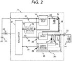
- FIG. 2 is a circuit configuration diagram of the ECU 11.
- the ECU 11 includes a microcomputer 21, a power-off relay 22, a voltage detection unit 23, a load drive circuit 25, and a capacitor 24.
- the power-off relay 22 is connected to the downstream side of an in-vehicle battery 13.
- the voltage smoothing capacitor 24 and the load drive circuit 25 are connected in parallel with each other on the downstream side of the power-off relay 22.
- the voltage detection unit 23 is connected to the upstream side and the downstream side of the power-off relay 22, monitors the upstream and downstream voltages of the power-off relay 22, and outputs the monitoring results to the microcomputer 21.
- the monitoring results input to the microcomputer 21 are an upstream voltage 42 and a downstream voltage 43.
- a switch 12 is connected to the downstream side of the in-vehicle battery 13, and turned on and off to start and stop the ECU 11.
- the power-off relay 22 is driven by a relay drive signal 37 to supply or cut off a power-supply voltage (voltage supplied by the in-vehicle battery 13) to a circuit arranged on the downstream side of the power-off relay 22. While the power-off relay 22 is on (energized), the upstream voltage 42 and the downstream voltage 43 of the power-off relay 22 are equal. While the power-off relay 22 is off (cut off), the upstream voltage 42 and the downstream voltage 43 of the power-off relay 22 are different from each other.
- the load drive circuit 25 is a circuit that controls a drive voltage for driving the electromagnetic induction load 14 and an energizing current 32 flowing through the electromagnetic induction load 14.
- the load drive circuit 25 includes a drive integrated circuit (IC) 26, a freewheeling diode 27, a current detection resistor 28, and a current detection unit 29.
- the drive IC 26 outputs the energizing current 32 to the electromagnetic induction load 14.
- the current detection unit 29 detects the actual load current 33 using the current detection resistor 28 and outputs the result as an actual current signal 38 to the microcomputer 21.
- the microcomputer 21 calculates the difference between a target current and the actual current signal 38 received from the current detection unit 29, determines the duty cycle of a drive signal 36 for operating the drive IC 26 based on the difference, and operates the drive IC 26.
- the energizing current 32 increases when the duty cycle of the drive signal 36 is high, and the energizing current 32 decreases when the duty cycle is low.
- the load current 33 includes the energizing current 32 output from the drive IC 26 and a freewheeling current 35 output from the freewheeling diode 27.
- the energizing current 32 flows only while the drive IC 26 is operating and does not flow while the drive IC 26 is not operating.
- the freewheeling current 35 flows only while the drive IC 26 is not operating after the drive IC 26 is changed from the operating state to the non-operating state.
- FIG. 3 is a flowchart for explaining a procedure in which the ECU 11 performs a failure diagnosis on the power-off relay 22. Each step of FIG. 3 will be described below. ( FIG. 3 : Step S100)
- the microcomputer 21 After the microcomputer 21 is started, it performs a self-failure diagnosis on the microcomputer 21 itself and its peripheral circuits to confirm that the ECU 11 can control the load properly, and shifts to a normal control mode. During the normal control, the load current 33 is controlled by repeatedly executing this flowchart based on various types of information input to the microcomputer 21. ( FIG. 3 : Step S110)
- the microcomputer 21 determines whether a relay diagnosis flag, which will be described later with reference to FIG. 4 , is on. If the relay diagnosis flag is on, steps S120 to S170 are executed. If the relay diagnosis flag is off, steps S210 to S260 are executed. Steps S210 to S260 are preprocessing steps that are performed before a relay failure diagnosis. Steps S120 to S170 are steps for a relay failure diagnosis process. In the following description, steps S210 to S260 will be described first for convenience of explanation. ( FIG. 3 : Steps S210 to S260: Supplement)
- the microcomputer 21 cuts off the power-off relay 22 in synchronization with the rise of the drive signal 36 according to the flowchart of FIG. 4 to be described later. While the power-off relay 22 is cut off, a discharge current 34 flows from the capacitor 24, and the downstream voltage 43 of the power-off relay 22 is decreased. If the decreased downstream voltage 43 falls between an upper limit threshold value and a lower limit threshold value, it is determined that the power-off relay 22 is normal. Steps S210 to S260 correspond to preprocessing steps for setting parameters for use in the diagnosis. ( FIG. 3 : Steps S210 to S220)
- the microcomputer 21 measures the load current 33 (S210) .
- the microcomputer 21 acquires the downstream voltage 43 of the power-off relay 22 from the voltage detection unit 23 (S220). ( FIG. 3 : Step S230)
- the microcomputer 21 calculates the time (cutoff-enabled time) during which the power-off relay 22 can be cut off. During the cutoff-enabled time for the power-off relay 22, the discharge current 34 is output by releasing the charge from the capacitor 24 while the power-off relay 22 is cut off, and it is possible to continue supplying the energizing current 32 using the discharge current 34. ( FIG. 3 : Step S230: Calculation Formula)
- the energizing current 32 measured in step S210 is assigned to the current I (discharge current of the capacitor 24), the downstream voltage 43 measured in step S220 is assigned to the voltage V (voltage between both ends of the capacitor 24), and the capacitance C of the capacitor 24 is used, whereby the cutoff-enabled time for the power-off relay 22 can be calculated.
- FIG. 3 Step S230: Calculation Example
- the microcomputer 21 sets the time (relay cutoff time) for actually cutting off the power-off relay 22 based on the cutoff-enabled time calculated in step S230.
- the relay cutoff time is shorter than the cutoff-enabled time. This is because if the relay cutoff time is longer than the cutoff-enabled time, it is impossible to continue supplying the discharge current 34 for supplementing the energizing current 32, and the control accuracy for driving the electromagnetic induction load 14 decreases due to the insufficient energizing current. ( FIG. 3 : Step S250)
- the drop voltage 44 of the downstream voltage 43 of the power-off relay 22 is calculated to be 10 [V] using Formula 4. Specifically, if the power-off relay 22 is cut off for 10 ms, the downstream voltage 43 of the power-off relay 22 decreases to 3.5 V. Assuming that the drop voltage that depends on circuit variations is ⁇ 1 V, the upper limit threshold value is 4.5 V, and the lower limit threshold value is 2.5 V. ( FIG. 3 : Step S260)
- the microcomputer 21 turns on the function of detecting the rise of the drive signal 36 of the drive IC 26. If this function is on, the flowchart to be described later with reference to FIG. 4 is executed. Specifically, steps S210 to S260 are preprocessing steps for executing the flowchart illustrated in FIG. 4 as an interrupt process. ( FIG. 3 : Step S120)
- the microcomputer 21 determines whether the relay cutoff time set in step S240 has elapsed by the present time since the power-off relay 22 was cut off. The elapsed time is measured with a timer to be described later with reference to FIG. 4 . If the relay cutoff time has not elapsed, the flowchart is ended (failure diagnosis on the power-off relay 22 is not executed) . If the relay cutoff time has elapsed, the process proceeds to step S130. ( FIG. 3 : Steps S130 to S140)
- the microcomputer 21 measures the downstream voltage 43 (S130). The microcomputer 21 determines whether the downstream voltage 43 falls between the upper limit threshold value and the lower limit threshold value set in step S250 (S140) . If the downstream voltage 43 falls between the upper limit threshold value and the lower limit threshold value (the power-off relay 22 is normal), the process proceeds to step S160. If the downstream voltage 43 does not fall between the upper limit threshold value and the lower limit threshold value (the power-off relay 22 is wrong), the process proceeds to step S150 . ( FIG. 3 : Steps S150 to S160)
- the microcomputer 21 If it is determined that the power-off relay 22 is wrong, the microcomputer 21 turns on a relay failure flag (S150) . If it is determined that the power-off relay 22 is normal, the microcomputer 21 turns off the relay diagnosis flag and resets the timer to be described later with reference to FIG. 4 (S160) . ( FIG. 3 : Step S170)
- the microcomputer 21 turns on the power-off relay 22 and ends the flowchart of FIG. 3 .
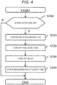
- FIG. 4 is the flowchart for explaining the interrupt process that is executed by the microcomputer 21.
- the microcomputer 21 executes this flowchart in synchronization with the rise of the drive signal 36.
- FIG. 4 Step S300
- the microcomputer 21 determines whether the function of detecting the rise of the drive signal 36 is on. If the function is not on, the flowchart is ended. If the function is on, the process proceeds to step S310. ( FIG. 4 : Step S310)
- the microcomputer 21 turns on the relay diagnosis flag. As a result, the microcomputer 21 shifts to an operation mode for executing a failure diagnosis on the power-off relay 22. ( FIG. 4 : Step S320)
- the microcomputer 21 turns off the function of detecting the rise of the drive signal 36. As a result, this flowchart is not executed while the failure diagnosis on the power-off relay 22 is being executed ("N" in S300) . ( FIG. 4 : Steps S330 to S340)
- the microcomputer 21 turns off the power-off relay 22 (S330).
- the microcomputer 21 starts the timer for measuring the time during which the power-off relay 22 is cut off (S340) .
- FIG. 5 is a timing chart for explaining a process in which the ECU 11 performs a failure diagnosis on the power-off relay 22.
- Time points t100 to t120 indicate one cycle of the drive signal for the load drive circuit 25.
- Time points t100 to t110 indicate the period during which the drive signal 36 is on, and the energizing current 32 flows through the electromagnetic induction load 14.
- Time points t110 to t120 indicate the period during which the drive signal 36 is off, and the freewheeling current 35 flows through the electromagnetic induction load 14.
- the microcomputer 21 executes steps S210 to S260 between time points t200 and t210.
- the microcomputer 21 detects the rise of the drive signal 36 and turns off the power-off relay 22.
- Time points t310 to t320 are the relay cutoff time, and the downstream voltage 43 decreases.
- the microcomputer 21 executes a failure diagnosis on the power-off relay 22 at time point t320.
- the ECU 11 can perform a failure diagnosis on the power-off relay 22 without affecting the accuracy of the drive control for the electromagnetic induction load 14 by cutting off the power-off relay 22 and supplementing the energizing current 32 with the discharge current 34 from the capacitor 24. As a result, it is possible to increase the frequency of detecting the failure of the power-off relay 22.
- FIG. 6 is a circuit configuration diagram of the ECU 11 according to a second embodiment of the present invention.
- the ECU 11 includes two load drive circuits 25.
- indices "a" and "b" are assigned to the load drive circuits 25 and their components in FIG. 6 .
- they are distinguished using these indices. Since the other configuration is the same as that of the first embodiment, differences will be mainly described below.
- FIG. 7 is a flowchart for explaining a procedure in which the ECU 11 performs a failure diagnosis on the power-off relay 22.
- step S200 is newly added. The other steps are the same as those of FIG. 3 . ( FIG. 7 : Step S200)
- the microcomputer 21 identifies the load drive circuit 25 in operation in order to confirm which load drive circuit 25 is operating while the following process is performed on the energizing current 32.
- FIG. 8 is a flowchart for explaining an interrupt process that is executed by the microcomputer 21.
- step S301 is newly added.
- the other steps are the same as those of FIG. 4 . ( FIG. 8 : Step S301)
- the microcomputer 21 determines whether the load drive circuit 25 identified in step S200 is on (in operation). If it is not on, the flowchart is ended. If it is on, the process proceeds to step S310. ( FIG. 8 : Step S301: Supplement)
- step S200 The purpose of this step is to prevent the downstream voltage 43 from being erroneously monitored even when a phase difference occurs between the operation timings of the plurality of load drive circuits 25 provided. For example, suppose it is identified in step S200 that the two load drive circuits 25 are operating. In this case, if step S301 is not performed, for example, there is a possibility that the power-off relay 22 is turned off while only the load drive circuit 25a is on. Specifically, even though the relay cutoff time and the drop voltage 44 are calculated in steps S200 to S260 under the assumption that the two load drive circuits 25a and 25b are operating, the power-off relay 22 may be turned off in step S320 while only the load drive circuit 25a is on.
- step S301 it is ensured that the operating state of the load drive circuits 25 for the case of calculating the drop voltage in steps S200 to S260 is the same as the operating state of the load drive circuits 25 in step S301 and subsequent steps. Therefore, the above-mentioned erroneous diagnosis can be prevented.
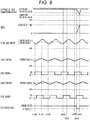
- FIG. 9 is a timing chart for explaining a process in which the ECU 11 performs a failure diagnosis on the power-off relay 22.
- Time points t100 to t200 are the same as those in the first embodiment.
- the microcomputer 21 identifies the load drive circuit 25 in operation, monitors the load current of each load drive circuit, and calculates the total load current 33.
- the microcomputer 21 detects the rise of the drive signal 36a and executes the interrupt process. Since only the load drive circuit 25a is operating at time point t300, the process of step S310 and subsequent steps is not executed.
- the microcomputer 21 detects the rise of the drive signal 36b and executes the interrupt process.
- step S310 Since both the load drive circuits 25a and 25b are operating at time point t310, the process of step S310 and subsequent steps is executed.
- the time between time points t310 and t320 is the relay cutoff time set in step S240.
- the microcomputer 21 executes a failure diagnosis on the power-off relay 22 at time point t320.
- the ECU 11 according to the second embodiment can perform a failure diagnosis on the power-off relay 22 without affecting the accuracy of the drive control for the electromagnetic induction load 14 in the same manner as the ECU 11 according to the first embodiment.
- the ECU 11 includes the two load drive circuits 25. However, a similar effect can be obtained even in a case where three or more load drive circuits 25 are provided.
- the second embodiment provides the method of performing a failure diagnosis on the power-off relay 22 while the plurality of load drive circuits 25 is operating. However, it is possible to perform a failure diagnosis on the power-off relay 22 while one of the plurality of load drive circuits 25 provided in the ECU 11 is operating. Further, it is possible to perform a failure diagnosis on the power-off relay 22 while the plurality of load drive circuits 25 is operating and there is no phase difference between the load drive circuits 25.
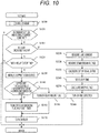
- FIG. 10 is a flowchart for explaining a procedure in which the ECU 11 according to a third embodiment of the present invention performs a failure diagnosis on the power-off relay 22.
- step S101 is newly added.
- the other steps are the same as those of FIG. 3 .
- the configuration of the ECU 11 and the flowchart of FIG. 4 are the same as those of the first embodiment. ( FIG. 10 : Step S101)
- the microcomputer 21 determines whether a target value of the load current 33 is constant and whether the load current 33 is settled. If the target current value is constant and the load current 33 is settled, the process proceeds to step S110. If the target current value is not constant or the load current 33 is not settled, the process skips to step S160. Specifically, in a state where the target current value is not constant or in a transient state where the load current 33 is not settled, the failure diagnosis on the power-off relay 22 is interrupted. ( FIG. 10 : Step S101: Supplement 1)
- the target value of the load current 33 may be changed during operation. Once the target value is changed, the microcomputer 21 controls the load current 33 toward the changed target value. If the failure diagnosis on the power-off relay 22 is performed during the period in which the load current 33 is not settled after the change of the target current value, there is a possibility that the following trouble may occur. If the actual load current 33 is smaller than the value used in calculating the relay cutoff time and the drop voltage in steps S210 to S260, the actual decrease in the downstream voltage 43 is smaller than the drop voltage calculated in step S250, and the failure of the power-off relay 22 is erroneously detected.
- step S101 it is possible to avoid erroneous detection of a failure and a decrease in the control accuracy.
- Whether the load current 33 is settled or not can be determined, for example, based on whether the load current 33 converges within the range of 95% to 105% of the target current. Other determination rules may be applied as appropriate.
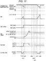
- FIG. 11 is a timing chart for explaining a process in which the ECU 11 performs a failure diagnosis on the power-off relay 22.
- the load current 33 and the drive signal 36 are a sawtooth wave and a rectangular wave, respectively, they are schematically indicated by straight lines in FIG. 11 .
- the microcomputer 21 turns off the power-off relay 22 and starts a failure diagnosis.
- the target current value is switched from a target value a to a target value b.
- Time points t311 to t400 correspond to the state where the target current value changes and the load current 33 is not settled. During this period, the microcomputer 21 interrupts the failure diagnosis on the power-off relay 22.
- Time point t400 and subsequent time points correspond to the state where the target current value is constant and the load current 33 is settled.
- the microcomputer 21 can perform a failure diagnosis on the power-off relay 22.
- steps S210 to S260 in the same manner as in FIG. 5 .
- the microcomputer 21 turns off the power-off relay 22 and executes a failure diagnosis in the same manner as in FIG. 5 .
- the ECU 11 according to the third embodiment interrupts the failure diagnosis on the power-off relay 22 during the period in which the load current 33 is transiently changing. As a result, it is possible to avoid erroneous detection of a failure and a decrease in the accuracy of the drive control for the electromagnetic induction load 14.
- the configuration and operation according to the third embodiment can also be applied, for example, to the second embodiment.
- FIG. 12 is a flowchart for explaining a procedure in which the ECU 11 according to a fourth embodiment of the present invention performs a failure diagnosis on the power-off relay 22.
- step S201 is newly added.
- the other steps are the same as those of FIG. 3 .
- the configuration of the ECU 11 and the flowchart of FIG. 4 are the same as those of the first embodiment. ( FIG. 12 : Step S201)
- the microcomputer 21 confirms whether the duty cycle of the drive signal 36 is such that no influence is exerted on the accuracy of the drive control for the electromagnetic induction load 14 even after the power-off relay 22 is cut off. Specifically, it is determined whether the duty cycle of the drive signal 36 falls between a duty cycle upper limit value and a duty cycle lower limit value. If the duty cycle of the drive signal 36 does not fall between the duty cycle upper limit value and the duty cycle lower limit value, the flowchart is ended. If the duty cycle of the drive signal 36 falls between the duty cycle upper limit value and the duty cycle lower limit value, the process proceeds to step S210. By adding step S201, it is possible to avoid overlooking a failure and decreasing the accuracy of the load drive control as described below. ( FIG. 12 : Step S201: Supplement 1)
- the energizing current 32 is sufficiently larger than the discharge current 34 from the capacitor 24, that is, in a case where the duty cycle of the drive signal 36 is high, the decrease rate of the downstream voltage 43 is fast after the power-off relay 22 is turned off to cause the discharge current 34 to flow from the capacitor 24.
- the load current 33 may not be supplemented with the discharge current 34.
- the energizing current 32 becomes insufficient, the electromagnetic induction load 14 cannot be sufficiently driven, and the accuracy of the drive control decreases.
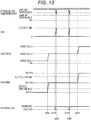
- FIG. 13 is a timing chart for explaining a process in which the ECU 11 performs a failure diagnosis on the power-off relay 22.
- the load current 33 and the drive signal 36 are a sawtooth wave and a rectangular wave, respectively, they are schematically indicated by straight lines in FIG. 13 .
- the drive signal 36 Before time point t500, the drive signal 36 is equal to or lower than the duty cycle lower limit value, and the microcomputer 21 does not perform a failure diagnosis on the power-off relay 22 in this period. After time point t510, the drive signal 36 is equal to or higher than the duty cycle upper limit value, and the microcomputer 21 does not perform a failure diagnosis on the power-off relay 22 in this period. During the period between time points t500 and t510, the duty cycle of the drive signal 36 falls between the duty cycle upper limit value and the duty cycle lower limit value, and the microcomputer 21 performs a failure diagnosis on the power-off relay 22 in this period.
- the ECU 11 according to the fourth embodiment can (a) suppress the possibility of overlooking the failure of the power-off relay 22 in a case where the energizing current 32 is sufficiently smaller than the discharge current 34 from the capacitor 24, and (b) suppress the possibility that the accuracy of the drive control for the electromagnetic induction load 14 decreases in a case where the energizing current 32 is sufficiently larger than the discharge current 34 from the capacitor 24.
- the configuration and operation according to the fourth embodiment can also be applied, for example, to the second embodiment.
- FIG. 14 is a flowchart for explaining a procedure in which the ECU 11 according to a fifth embodiment of the present invention performs a failure diagnosis on the power-off relay 22.
- steps S102 to S103 and S180 are newly added.
- the other steps are the same as those of FIG. 3 .
- the configuration of the ECU 11 and the flowchart of FIG. 4 are the same as those of the first embodiment. ( FIG. 14 : Step S180)
- the microcomputer 21 starts measuring the charging time for the capacitor 24.
- the current measurement value is reset.
- the downstream voltage 43 is low.
- the capacitor 24 starts being charged at the time that the power-off relay 22 is turned on in step S170, and the downstream voltage 43 starts to rise. This step is for measuring the charging time from the start of the charging for the capacitor 24. ( FIG. 14 : Step S102)
- the microcomputer 21 determines whether sufficient time to charge the capacitor 24 has elapsed. More specifically, it is determined whether the charging time exceeds a charging time threshold value. If the charging time does not exceed the charging time threshold value, the flowchart is ended, and the failure diagnosis (steps S103 to S180) on the power-off relay 22 is not executed. If the charging time exceeds the charging time threshold value, the process proceeds to step S103.
- the charging time threshold value can be set using, for example, the time t obtained by applying the capacitance C of the capacitor 24, the voltage V, and the charging current for the capacitor 24 to Formula 3. ( FIG. 14 : Step S103)
- the microcomputer 21 determines whether the downstream voltage 43 exceeds a charging voltage threshold value. If the downstream voltage 43 does not exceed the charging voltage threshold value, the flowchart is ended, and the failure diagnosis (steps S110 to S180) on the power-off relay 22 is not executed. If the downstream voltage 43 exceeds the charging voltage threshold value, the process proceeds to step S110.
- the charging voltage threshold value may be set to a freely-selected ratio to the downstream voltage 43 measured in step S220. ( FIG. 14 : Steps S102 to S103 and S180: Supplement)
- the downstream voltage 43 is low. If the failure diagnosis on the power-off relay 22 is restarted in this state, the relay cutoff time for the power-off relay 22 and the drop voltage calculated using Formulas 3 and 4 are extremely short and small, respectively. As a result, even if the power-off relay 22 is in failure, there is a possibility that the state of the power-off relay 22 is erroneously diagnosed as a normal state due to the power supply fluctuation occurring at the upstream voltage 42. By adding steps S102, S103, and S180, the failure diagnosis on the power-off relay 22 is interrupted immediately after the failure diagnosis on the power-off relay 22 is completed, whereby erroneous diagnosis can be avoided.
- FIG. 15 is a timing chart for explaining a process in which the ECU 11 performs a failure diagnosis on the power-off relay 22.
- the load current 33 and the drive signal 36 are a sawtooth wave and a rectangular wave, respectively, they are schematically indicated by straight lines in FIG. 15 .
- steps S210 to S260 are executed.
- steps S110 to S180 are executed.
- the microcomputer 21 starts measuring the charging time at time point t320 when the failure diagnosis on the power-off relay 22 is completed.
- Time point t600 is the timing at which the charging time exceeds the charging time threshold value.
- the microcomputer 21 monitors the downstream voltage 43 at time point t600, and performs a failure diagnosis on the power-off relay 22 if it exceeds the charging threshold value. After the failure diagnosis is completed, at time point t320, the microcomputer 21 resets the timer for measuring the charging time, and starts measuring the charging time again.
- the ECU 11 according to the fifth embodiment does not restart the failure diagnosis immediately after the failure diagnosis on the power-off relay 22 is completed. As a result, erroneous diagnosis on the power-off relay 22 can be avoided.
- the configuration and operation according to the fifth embodiment can also be applied, for example, to the second embodiment.
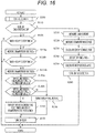
- FIG. 16 is a flowchart for explaining a procedure in which the ECU 11 according to a sixth embodiment of the present invention performs a failure diagnosis on the power-off relay 22.
- steps S120 to S140b and steps S240 and S250 are changed.
- the configuration of the ECU 11 and the flowchart of FIG. 4 are the same as those of the first embodiment. ( FIG. 16 : Step S240)
- the microcomputer 21 sets the relay cutoff time a and the relay cutoff time b.
- the relay cutoff time a is set shorter than the relay cutoff time b.
- the relay cutoff time b is the time for actually cutting off the power-off relay 22 (same as the relay cutoff time in the first embodiment) . ( FIG. 16 : Step S250)
- the microcomputer 21 calculates the drop voltage a of the downstream voltage 43a based on the relay cutoff time a. Further, based on the relay cutoff time b, the drop voltage b of the downstream voltage 43b is calculated. The microcomputer 21 further sets the upper limit threshold values a and b and the lower limit threshold values a and b corresponding to the drop voltages a and b, respectively. The distinction between the downstream voltages 43a and 43b will be described later. ( FIG. 16 : Step S120)
- the microcomputer 21 determines whether the relay cutoff time a has elapsed since the power-off relay 22 was turned off. If the elapsed time does not exceed the relay cutoff time a, the flowchart is ended, and the diagnosis process for the power-off relay 22 in step S130a and subsequent steps is not performed. If the elapsed time exceeds the relay cutoff time a, the process proceeds to step S130a. ( FIG. 16 : Step S130a)
- the microcomputer 21 determines whether the downstream voltage 43a has already been measured. If it has not been measured yet, the downstream voltage 43a of the power-off relay 22 is measured. If it has already been measured, the downstream voltage 43a of the power-off relay 22 is not measured. In this flowchart, since the downstream voltage 43 is measured twice, indices a and b are used to distinguish them. ( FIG. 16 : Step S130b)
- the microcomputer 21 determines whether the relay cutoff time b has elapsed since the power-off relay 22 was turned off. If the elapsed time does not exceed the relay cutoff time b, the flowchart is ended, and the diagnosis process for the power-off relay 22 in step S131b and subsequent steps is not performed. If the elapsed time exceeds the relay cutoff time b, the process proceeds to step S131b. ( FIG. 16 : Step S130b)
- the microcomputer 21 measures the downstream voltage 43b. ( FIG. 16 : Steps S140a to S140b)
- the microcomputer 21 determines whether the downstream voltage 43a falls between the upper limit threshold value a and the lower limit threshold value a (S140a). The microcomputer 21 also determines whether the downstream voltage 43b falls between the upper limit threshold value b and the lower limit threshold value b (S140b). If either of the determination conditions of step S140a and step S140b is not satisfied, the process proceeds to step S150. If both of the determination conditions of step S140a and step S140b are satisfied, the process proceeds to step S160. ( FIG. 16 : Step S160)
- the microcomputer 21 resets the downstream voltages 43a and 43b in addition to resetting the relay diagnosis flag and the timer.
- FIG. 17 is a timing chart for explaining a process in which the ECU 11 performs a failure diagnosis on the power-off relay 22.
- the power-off relay 22 is off.
- Time point t310 corresponds to the relay cutoff time a
- time point t320 corresponds to the relay cutoff time b.
- the microcomputer 21 measures the downstream voltage 43a.
- the microcomputer 21 measures the downstream voltage 43b. The microcomputer 21 determines whether the downstream voltages at time points t311 and t320 fall between the upper and lower limit threshold values a and b, respectively.
- the downstream voltage 43 may fall within the range of the upper and lower limit threshold values. Then, the microcomputer 21 erroneously diagnoses that the power-off relay 22 is normal even though the power-off relay 22 is suffering the short-circuit failure.
- the ECU 11 monitors the downstream voltage 43 of the power-off relay 22 multiple times while the power-off relay 22 is suffering the short-circuit failure, and if the downstream voltage 43 that is out of the range of the upper and lower limit threshold values is detected at least once, it is determined that the power-off relay 22 is in a failure state. As a result, erroneous diagnosis due to the above phenomenon can be avoided.
- the configuration and operation according to the sixth embodiment can also be applied, for example, to the second embodiment. A similar effect can be obtained by setting a plurality of periods of relay cutoff time 1 in the sixth embodiment.
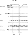
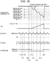
- FIG. 18 is a timing chart for explaining a process in which the ECU 11 according to a seventh embodiment of the present invention performs a failure diagnosis on the power-off relay 22.
- the configuration of the ECU 11 and the flowchart of FIG. 4 are the same as those of the first embodiment.
- the downstream voltage 43 is measured at the time that the timer reaches the relay cutoff time 1 and the relay cutoff time 2.
- the downstream voltage 43 is measured at the falling timing of the drive signal 36 for the load drive circuit 25. Therefore, the microcomputer 21 measures the downstream voltage 43 between time points t312 and t314. Since the downstream voltage 43 decreases in a stepwise manner in synchronization with the drive signal 36, the downstream voltage 43 is measured in synchronization with the drive signal 36.
- the microcomputer 21 diagnoses at time point t320 that each of the downstream voltages 43 between time points t312 and t314 falls within the range of the upper and lower limit threshold values. An effect similar to that of the sixth embodiment can be obtained with this method.
- the configuration and operation according to the seventh embodiment can also be applied, for example, to the second embodiment.
- FIG. 19 is a circuit configuration diagram of the ECU 11 according to an eighth embodiment of the present invention.
- the current detection unit 29 is configured as a part of the drive IC 26.
- the process of controlling the load current 33 is performed by a current control unit 51 included in the drive IC 26. Therefore, in the eighth embodiment, in contrast to the first embodiment, the microcomputer 21 cannot detect the rise of the drive signal 36. Therefore, the ECU 11 according to the eighth embodiment further includes a voltage detection unit 52.
- the voltage detection unit 52 monitors the output terminal waveform (that is, load voltage) of the drive IC 26 and notifies the microcomputer 21 of the result as a load voltage 31.
- the microcomputer 21 synchronizes the timing of turning off the power-off relay 22 with the rise of the output terminal waveform.
- FIG. 20 is a flowchart for explaining a procedure in which the ECU 11 according to the eighth embodiment performs a failure diagnosis on the power-off relay 22. Although this flowchart is substantially the same as that of FIG. 3 , the microcomputer 21 turns on the function of detecting the rise of the load voltage 31 in step S260 in accordance with the above configuration of the ECU 11.
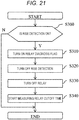
- FIG. 21 is a flowchart for explaining an interrupt process that is executed by the microcomputer 21. Although this flowchart is substantially the same as that of FIG. 4 , the microcomputer 21 determines whether the function of detecting the rise of the load voltage 31 is on in step S300 in accordance with the above configuration of the ECU 11.
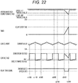
- FIG. 22 is a timing chart for explaining a process in which the ECU 11 performs a failure diagnosis on the power-off relay 22.
- FIG. 22 is the same as FIG. 5 except that the load voltage 31 is used instead of the drive signal 36. Since the load voltage 31 is supplied from the drive IC 25 during the period between time points t100 and t110, the load voltage 31 corresponds to the downstream voltage 43 of the power-off relay 22. Between time points t110 and t120, the drive IC 26 is stopped, and the freewheeling current 35 flows through the electromagnetic induction load 14 via the freewheeling diode 27. Therefore, the load voltage 31 is a minus voltage corresponding to the forward voltage of the freewheeling diode 27.
- the microcomputer 21 executes the preprocessing steps (steps S210 to S260) for the failure diagnosis on the power-off relay 22.
- the microcomputer 21 detects the rise of the load voltage 31, and executes steps S120 to S170.
- the ECU 11 according to the eighth embodiment can execute a failure diagnosis on the power-off relay 22 in the same manner as in the first embodiment using the load voltage 31.
- the configuration according to the eighth embodiment can also be applied, for example, to a circuit configuration including a plurality of load drive circuits 25 as in the second embodiment.
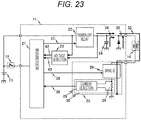
- FIG. 23 is a circuit configuration diagram of the ECU 11 according to a ninth embodiment of the present invention.
- the ninth embodiment is different from the first embodiment in that the load drive circuit 25 is replaced by a low-side load drive circuit.
- An effect similar to that of the first embodiment can be obtained with the low-side load drive circuit 25.
- An effect similar to that of the second embodiment can be obtained with the ECU 11 including a plurality of low-side load drive circuits 25 as in the second embodiment.
- the present invention is not limited to the above-mentioned examples, and includes a variety of modifications.
- the above-mentioned examples have been explained in detail for an easy understanding of the present invention, the present invention is not necessarily limited to what is provided with all of the described configurations.
- one example configuration can be partially replaced by another example configuration, and can be supplemented by another example configuration.
- Each example configuration can be partially deleted, or can be supplemented by/exchanged for another configuration.
- the present invention is not limited to the automatic transmission for a vehicle. An effect similar to that of the present invention can be obtained even in a case where the present invention is applied to a control device for a vehicle (e.g., engine control device) including a similar circuit configuration for driving an electromagnetic induction load.
- a control device for a vehicle e.g., engine control device
Landscapes
- Engineering & Computer Science (AREA)
- Mechanical Engineering (AREA)
- Physics & Mathematics (AREA)
- General Physics & Mathematics (AREA)
- Electronic Switches (AREA)
- Testing Electric Properties And Detecting Electric Faults (AREA)
Claims (9)
- Fahrzeuginterne Steuervorrichtung (11), die ausgelegt ist, ein Relais (22) zu steuern, das konfiguriert ist, einen Erregungsstrom für eine elektromagnetische Induktionslast (14) auszuschalten, wobei sie einen Kondensator (24) umfasst, der zwischen dem Relais (22) und der elektromagnetischen Induktionslast (14) angeschlossen ist, dadurch gekennzeichnet, dass
die fahrzeuginterne Steuervorrichtung (11)
das Relais (22) für einen vorgegebenen Zeitraum ausschaltet, während die elektromagnetische Induktionslast (14) erregt ist, und
das Relais (22) auf der Grundlage einer Spannung eines Abschnitts in Reihe mit dem Relais (22) diagnostiziert, die erhalten wird, wenn das Relais (22) ausgeschaltet ist,
die fahrzeuginterne Steuervorrichtung (11) die Zeit berechnet, während der das Relais (22) ausgeschaltet sein kann und der Kondensator (14) der elektromagnetischen Induktionslast (14) einen Erregungsstrom (32) zuführen kann, wobei
die fahrzeuginterne Steuervorrichtung (11) das Relais (22) ausschaltet, wenn ein Tastverhältnis eines Signals, das die elektromagnetische Induktionslast (14) ansteuert, in einen Schwellenwertbereich abfällt, in dem bestimmt wird, dass das Relais (22) ausgeschaltet werden kann. - Fahrzeuginterne Steuervorrichtung (11) nach Anspruch 1, wobei
die fahrzeuginterne Steuervorrichtung (11) einen Strom überwacht, der durch die elektromagnetische Induktionslast (14) fließt, während die elektromagnetische Induktionslast (14) angesteuert wird, und
der vorgegebene Zeitraum ein Zeitraum ist, in dem der Strom, der durch die elektromagnetische Induktionslast (14) fließt, durch das Entladen einer Ladung im Kondensator (24) ergänzt werden kann, während das Relais (22) ausgeschaltet ist. - Fahrzeuginterne Steuervorrichtung (11) nach Anspruch 2, wobei die fahrzeuginterne Steuervorrichtung (11)
den Zeitraum berechnet, in dem der Strom, der durch die elektromagnetische Induktionslast (14) fließt, durch das Entladen der Ladung im Kondensator (24) ergänzt werden kann, während das Relais (22) ausgeschaltet ist, und
eine Spannung des Abschnitts in Reihe mit dem Relais (22) für einen Fall, in dem das Relais (22) für den Zeitraum ausgeschaltet ist, berechnet. - Fahrzeuginterne Steuervorrichtung (11) nach einem der Ansprüche 1 bis 3, wobei
die fahrzeuginterne Steuervorrichtung (11)
das Relais (22) lediglich dann ausschaltet, während sich der Strom, der durch die elektromagnetische Induktionslast (14) fließt, in einem konstanten Zustand befindet, und
eine Fehlerdiagnose auf dem Relais (22) durchführt, ohne das Relais (22) auszuschalten, während der Strom, der durch die elektromagnetische Induktionslast (14) fließt, vorübergehend schwankt. - Fahrzeuginterne Steuervorrichtung (11) nach Anspruch 2 oder 3, wobei
die fahrzeuginterne Steuervorrichtung (11) nach einer Fehlerdiagnose an dem Relais (22) die Fehlerdiagnose an dem Relais (22) unterbricht, bis der Kondensator (24) mit einer Spannung aufgeladen ist. - Fahrzeuginterne Steuervorrichtung (11) nach einem der Ansprüche 1 bis 3, wobei
die fahrzeuginterne Steuervorrichtung (11) in mehreren Wiederholungen die Spannung des Abschnitts in Reihe mit dem Relais (22) überwacht, die abfällt, während das Relais (22) ausgeschaltet ist, und das Relais (22) diagnostiziert. - Fahrzeuginterne Steuervorrichtung (11) nach einem der Ansprüche 1 bis 6, wobei
die elektromagnetische Induktionslast (14) mehrere elektromagnetische Induktionslasten (14a, 14b) enthält und die mehreren elektromagnetischen Induktionslasten (14a, 14b) mit dem Abschnitt in Reihe mit dem Relais (22) parallel geschaltet sind, und
die fahrzeuginterne Steuervorrichtung (11) die Spannung des Abschnitts in Reihe mit dem Relais (22) überwacht, wenn die Anzahl der erregten elektromagnetischen Induktionslasten der mehreren elektromagnetischen Induktionslasten (14a, 14b) kleiner als eine vorgegebene Anzahl ist. - Fahrzeuginterne Steuervorrichtung (11) nach einem der Ansprüche 1 bis 7, wobei
die fahrzeuginterne Steuervorrichtung (11) das Relais (22) auf der Grundlage einer Potentialdifferenz zwischen dem Abschnitt in Reihe mit dem Relais (22) und einem Massepotential diagnostiziert. - Fahrzeuginternes Steuersystem, das Folgendes umfasst:eine elektromagnetische Induktionslast (14);ein Relais (22), das konfiguriert ist, einen Erregungsstrom für die elektromagnetische Induktionslast (14) auszuschalten; undeine fahrzeuginterne Steuervorrichtung (11) nach Anspruch 1, die konfiguriert ist, die elektromagnetische Induktionslast (14) und das Relais (22) zu steuern.
Applications Claiming Priority (2)
| Application Number | Priority Date | Filing Date | Title |
|---|---|---|---|
| JP2015145402 | 2015-07-23 | ||
| PCT/JP2016/064671 WO2017013934A1 (ja) | 2015-07-23 | 2016-05-18 | 車載制御装置、車載制御システム |
Publications (3)
| Publication Number | Publication Date |
|---|---|
| EP3327746A1 EP3327746A1 (de) | 2018-05-30 |
| EP3327746A4 EP3327746A4 (de) | 2019-06-19 |
| EP3327746B1 true EP3327746B1 (de) | 2020-08-19 |
Family
ID=57833897
Family Applications (1)
| Application Number | Title | Priority Date | Filing Date |
|---|---|---|---|
| EP16827498.3A Active EP3327746B1 (de) | 2015-07-23 | 2016-05-18 | Steuerungsvorrichtung an bord eines fahrzeugs und steuerungssystem an bord eines fahrzeugs |
Country Status (5)
| Country | Link |
|---|---|
| US (1) | US10710524B2 (de) |
| EP (1) | EP3327746B1 (de) |
| JP (1) | JP6445699B2 (de) |
| CN (1) | CN107851537B (de) |
| WO (1) | WO2017013934A1 (de) |
Families Citing this family (7)
| Publication number | Priority date | Publication date | Assignee | Title |
|---|---|---|---|---|
| WO2017130669A1 (ja) * | 2016-01-29 | 2017-08-03 | 日立オートモティブシステムズ株式会社 | 電磁負荷駆動装置、車載制御システム |
| JP6929155B2 (ja) * | 2017-07-26 | 2021-09-01 | Kyb株式会社 | 駆動回路の異常診断装置 |
| JP6840712B2 (ja) * | 2018-11-29 | 2021-03-10 | 矢崎総業株式会社 | 車載システム |
| CN113966492A (zh) * | 2019-06-24 | 2022-01-21 | 日立安斯泰莫株式会社 | 车载控制装置 |
| JP7247923B2 (ja) * | 2020-02-25 | 2023-03-29 | 株式会社デンソー | 車両制御の故障診断装置 |
| JP7463814B2 (ja) | 2020-04-01 | 2024-04-09 | マツダ株式会社 | 車両のバッテリーシステム |
| WO2024004140A1 (ja) * | 2022-06-30 | 2024-01-04 | 株式会社オートネットワーク技術研究所 | 車載用遮断制御装置 |
Family Cites Families (13)
| Publication number | Priority date | Publication date | Assignee | Title |
|---|---|---|---|---|
| JP2006310091A (ja) | 2005-04-28 | 2006-11-09 | Toyota Motor Corp | リレー制御装置 |
| JP4509914B2 (ja) | 2005-11-14 | 2010-07-21 | 三菱電機株式会社 | 故障診断装置 |
| JP2007159326A (ja) * | 2005-12-07 | 2007-06-21 | Honda Motor Co Ltd | 電源制御装置 |
| JP4765859B2 (ja) | 2006-09-15 | 2011-09-07 | 株式会社アドヴィックス | 車両用制動装置の異常診断装置、及び車両用制動装置の異常診断方法 |
| JP2008293057A (ja) | 2007-05-22 | 2008-12-04 | Hitachi Ltd | 負荷駆動回路 |
| US8620504B2 (en) * | 2009-02-25 | 2013-12-31 | Toyota Jidosha Kabushiki Kaisha | Device and method for controlling vehicle |
| JP5587689B2 (ja) * | 2010-07-12 | 2014-09-10 | 日立オートモティブシステムズ株式会社 | 車両の故障診断装置 |
| JP5983171B2 (ja) * | 2012-08-10 | 2016-08-31 | 株式会社Gsユアサ | スイッチ故障診断装置、蓄電装置 |
| JP6139130B2 (ja) * | 2012-12-27 | 2017-05-31 | 矢崎総業株式会社 | 電磁誘導負荷の制御装置 |
| JP6244110B2 (ja) | 2013-05-31 | 2017-12-06 | 日本電産エレシス株式会社 | 電子制御装置 |
| CN103439650B (zh) * | 2013-08-07 | 2016-04-06 | 王岩 | 一种继电器状态监测与故障诊断的方法和装置 |
| JP6331510B2 (ja) * | 2014-03-12 | 2018-05-30 | 株式会社ジェイテクト | 電磁クラッチの制御装置 |
| JP6460642B2 (ja) | 2014-05-16 | 2019-01-30 | シャープ株式会社 | 開閉器の制御装置 |
-
2016
- 2016-05-18 EP EP16827498.3A patent/EP3327746B1/de active Active
- 2016-05-18 US US15/743,566 patent/US10710524B2/en active Active
- 2016-05-18 CN CN201680025590.0A patent/CN107851537B/zh active Active
- 2016-05-18 WO PCT/JP2016/064671 patent/WO2017013934A1/ja active Application Filing
- 2016-05-18 JP JP2017529485A patent/JP6445699B2/ja active Active
Non-Patent Citations (1)
| Title |
|---|
| None * |
Also Published As
| Publication number | Publication date |
|---|---|
| CN107851537B (zh) | 2020-05-01 |
| JPWO2017013934A1 (ja) | 2018-02-08 |
| US20180201209A1 (en) | 2018-07-19 |
| EP3327746A1 (de) | 2018-05-30 |
| WO2017013934A1 (ja) | 2017-01-26 |
| CN107851537A (zh) | 2018-03-27 |
| US10710524B2 (en) | 2020-07-14 |
| EP3327746A4 (de) | 2019-06-19 |
| JP6445699B2 (ja) | 2018-12-26 |
Similar Documents
| Publication | Publication Date | Title |
|---|---|---|
| EP3327746B1 (de) | Steuerungsvorrichtung an bord eines fahrzeugs und steuerungssystem an bord eines fahrzeugs | |
| US8924059B2 (en) | Electronic control device and vehicle control system | |
| US20030079163A1 (en) | Microprocessor runaway monitoring control circuit | |
| US9622304B2 (en) | Load driving circuit | |
| US11626742B2 (en) | Battery control device for homogenizing battery cells | |
| JP2015217911A (ja) | 電子制御装置 | |
| JP2013200714A (ja) | 監視装置および車載型電子制御装置 | |
| JP2008298643A (ja) | パック電池の内部消費電流異常の検出方法 | |
| US9354695B2 (en) | Power supply apparatus, processing apparatus, and information processing system | |
| JP5928358B2 (ja) | 情報処理装置、監視装置、制御装置 | |
| JP2007041824A (ja) | 電子制御ユニットのリセット回路 | |
| JP2009267258A (ja) | ソレノイド駆動装置 | |
| EP3982540A1 (de) | Schaltersteuervorrichtung, schaltersteuerverfahren und fahrzeugstromversorgungssystem | |
| JP6625668B2 (ja) | 電磁負荷駆動装置、車載制御システム | |
| US11656276B2 (en) | Monitoring circuit and method for function monitoring | |
| CN105320028A (zh) | 负载控制备用信号生成电路 | |
| US11305669B2 (en) | Electronic control device | |
| US10164446B2 (en) | Discharge circuit malfunction diagnosis device and discharge circuit malfunction diagnosis method | |
| JP2004362139A (ja) | 制御装置 | |
| JP6379070B2 (ja) | リレー回路故障診断装置 | |
| US20240042951A1 (en) | Vehicle-Mounted Control Device | |
| JP2013161240A (ja) | 電子制御装置 | |
| CN109878332B (zh) | 电源系统 | |
| JP2013143818A (ja) | 半導体ヒューズ装置 | |
| CN115811123A (zh) | 电源控制装置以及电源控制方法 |
Legal Events
| Date | Code | Title | Description |
|---|---|---|---|
| STAA | Information on the status of an ep patent application or granted ep patent |
Free format text: STATUS: THE INTERNATIONAL PUBLICATION HAS BEEN MADE |
|
| PUAI | Public reference made under article 153(3) epc to a published international application that has entered the european phase |
Free format text: ORIGINAL CODE: 0009012 |
|
| STAA | Information on the status of an ep patent application or granted ep patent |
Free format text: STATUS: REQUEST FOR EXAMINATION WAS MADE |
|
| 17P | Request for examination filed |
Effective date: 20180223 |
|
| AK | Designated contracting states |
Kind code of ref document: A1 Designated state(s): AL AT BE BG CH CY CZ DE DK EE ES FI FR GB GR HR HU IE IS IT LI LT LU LV MC MK MT NL NO PL PT RO RS SE SI SK SM TR |
|
| AX | Request for extension of the european patent |
Extension state: BA ME |
|
| RIN1 | Information on inventor provided before grant (corrected) |
Inventor name: JYUMONJI, KENTAROU |
|
| DAV | Request for validation of the european patent (deleted) | ||
| DAX | Request for extension of the european patent (deleted) | ||
| A4 | Supplementary search report drawn up and despatched |
Effective date: 20190521 |
|
| RIC1 | Information provided on ipc code assigned before grant |
Ipc: B60R 16/02 20060101ALI20190515BHEP Ipc: H01H 47/00 20060101AFI20190515BHEP |
|
| GRAP | Despatch of communication of intention to grant a patent |
Free format text: ORIGINAL CODE: EPIDOSNIGR1 |
|
| STAA | Information on the status of an ep patent application or granted ep patent |
Free format text: STATUS: GRANT OF PATENT IS INTENDED |
|
| INTG | Intention to grant announced |
Effective date: 20200511 |
|
| GRAS | Grant fee paid |
Free format text: ORIGINAL CODE: EPIDOSNIGR3 |
|
| GRAA | (expected) grant |
Free format text: ORIGINAL CODE: 0009210 |
|
| STAA | Information on the status of an ep patent application or granted ep patent |
Free format text: STATUS: THE PATENT HAS BEEN GRANTED |
|
| AK | Designated contracting states |
Kind code of ref document: B1 Designated state(s): AL AT BE BG CH CY CZ DE DK EE ES FI FR GB GR HR HU IE IS IT LI LT LU LV MC MK MT NL NO PL PT RO RS SE SI SK SM TR |
|
| REG | Reference to a national code |
Ref country code: CH Ref legal event code: EP |
|
| REG | Reference to a national code |
Ref country code: DE Ref legal event code: R096 Ref document number: 602016042462 Country of ref document: DE |
|
| REG | Reference to a national code |
Ref country code: AT Ref legal event code: REF Ref document number: 1304895 Country of ref document: AT Kind code of ref document: T Effective date: 20200915 |
|
| REG | Reference to a national code |
Ref country code: IE Ref legal event code: FG4D |
|
| REG | Reference to a national code |
Ref country code: LT Ref legal event code: MG4D |
|
| REG | Reference to a national code |
Ref country code: NL Ref legal event code: MP Effective date: 20200819 |
|
| PG25 | Lapsed in a contracting state [announced via postgrant information from national office to epo] |
Ref country code: BG Free format text: LAPSE BECAUSE OF FAILURE TO SUBMIT A TRANSLATION OF THE DESCRIPTION OR TO PAY THE FEE WITHIN THE PRESCRIBED TIME-LIMIT Effective date: 20201119 Ref country code: SE Free format text: LAPSE BECAUSE OF FAILURE TO SUBMIT A TRANSLATION OF THE DESCRIPTION OR TO PAY THE FEE WITHIN THE PRESCRIBED TIME-LIMIT Effective date: 20200819 Ref country code: HR Free format text: LAPSE BECAUSE OF FAILURE TO SUBMIT A TRANSLATION OF THE DESCRIPTION OR TO PAY THE FEE WITHIN THE PRESCRIBED TIME-LIMIT Effective date: 20200819 Ref country code: GR Free format text: LAPSE BECAUSE OF FAILURE TO SUBMIT A TRANSLATION OF THE DESCRIPTION OR TO PAY THE FEE WITHIN THE PRESCRIBED TIME-LIMIT Effective date: 20201120 Ref country code: LT Free format text: LAPSE BECAUSE OF FAILURE TO SUBMIT A TRANSLATION OF THE DESCRIPTION OR TO PAY THE FEE WITHIN THE PRESCRIBED TIME-LIMIT Effective date: 20200819 Ref country code: FI Free format text: LAPSE BECAUSE OF FAILURE TO SUBMIT A TRANSLATION OF THE DESCRIPTION OR TO PAY THE FEE WITHIN THE PRESCRIBED TIME-LIMIT Effective date: 20200819 Ref country code: PT Free format text: LAPSE BECAUSE OF FAILURE TO SUBMIT A TRANSLATION OF THE DESCRIPTION OR TO PAY THE FEE WITHIN THE PRESCRIBED TIME-LIMIT Effective date: 20201221 Ref country code: NO Free format text: LAPSE BECAUSE OF FAILURE TO SUBMIT A TRANSLATION OF THE DESCRIPTION OR TO PAY THE FEE WITHIN THE PRESCRIBED TIME-LIMIT Effective date: 20201119 |
|
| REG | Reference to a national code |
Ref country code: AT Ref legal event code: MK05 Ref document number: 1304895 Country of ref document: AT Kind code of ref document: T Effective date: 20200819 |
|
| PG25 | Lapsed in a contracting state [announced via postgrant information from national office to epo] |
Ref country code: NL Free format text: LAPSE BECAUSE OF FAILURE TO SUBMIT A TRANSLATION OF THE DESCRIPTION OR TO PAY THE FEE WITHIN THE PRESCRIBED TIME-LIMIT Effective date: 20200819 Ref country code: PL Free format text: LAPSE BECAUSE OF FAILURE TO SUBMIT A TRANSLATION OF THE DESCRIPTION OR TO PAY THE FEE WITHIN THE PRESCRIBED TIME-LIMIT Effective date: 20200819 Ref country code: RS Free format text: LAPSE BECAUSE OF FAILURE TO SUBMIT A TRANSLATION OF THE DESCRIPTION OR TO PAY THE FEE WITHIN THE PRESCRIBED TIME-LIMIT Effective date: 20200819 Ref country code: LV Free format text: LAPSE BECAUSE OF FAILURE TO SUBMIT A TRANSLATION OF THE DESCRIPTION OR TO PAY THE FEE WITHIN THE PRESCRIBED TIME-LIMIT Effective date: 20200819 Ref country code: IS Free format text: LAPSE BECAUSE OF FAILURE TO SUBMIT A TRANSLATION OF THE DESCRIPTION OR TO PAY THE FEE WITHIN THE PRESCRIBED TIME-LIMIT Effective date: 20201219 |
|
| REG | Reference to a national code |
Ref country code: DE Ref legal event code: R082 Ref document number: 602016042462 Country of ref document: DE Representative=s name: MERH-IP MATIAS ERNY REICHL HOFFMANN PATENTANWA, DE Ref country code: DE Ref legal event code: R081 Ref document number: 602016042462 Country of ref document: DE Owner name: HITACHI ASTEMO, LTD., HITACHINAKA-SHI, JP Free format text: FORMER OWNER: HITACHI AUTOMOTIVE SYSTEMS, LTD., HITACHINAKA-SHI, IBARAKI, JP |
|
| PG25 | Lapsed in a contracting state [announced via postgrant information from national office to epo] |
Ref country code: CZ Free format text: LAPSE BECAUSE OF FAILURE TO SUBMIT A TRANSLATION OF THE DESCRIPTION OR TO PAY THE FEE WITHIN THE PRESCRIBED TIME-LIMIT Effective date: 20200819 Ref country code: DK Free format text: LAPSE BECAUSE OF FAILURE TO SUBMIT A TRANSLATION OF THE DESCRIPTION OR TO PAY THE FEE WITHIN THE PRESCRIBED TIME-LIMIT Effective date: 20200819 Ref country code: RO Free format text: LAPSE BECAUSE OF FAILURE TO SUBMIT A TRANSLATION OF THE DESCRIPTION OR TO PAY THE FEE WITHIN THE PRESCRIBED TIME-LIMIT Effective date: 20200819 Ref country code: SM Free format text: LAPSE BECAUSE OF FAILURE TO SUBMIT A TRANSLATION OF THE DESCRIPTION OR TO PAY THE FEE WITHIN THE PRESCRIBED TIME-LIMIT Effective date: 20200819 Ref country code: EE Free format text: LAPSE BECAUSE OF FAILURE TO SUBMIT A TRANSLATION OF THE DESCRIPTION OR TO PAY THE FEE WITHIN THE PRESCRIBED TIME-LIMIT Effective date: 20200819 |
|
| REG | Reference to a national code |
Ref country code: DE Ref legal event code: R097 Ref document number: 602016042462 Country of ref document: DE |
|
| PG25 | Lapsed in a contracting state [announced via postgrant information from national office to epo] |
Ref country code: ES Free format text: LAPSE BECAUSE OF FAILURE TO SUBMIT A TRANSLATION OF THE DESCRIPTION OR TO PAY THE FEE WITHIN THE PRESCRIBED TIME-LIMIT Effective date: 20200819 Ref country code: AT Free format text: LAPSE BECAUSE OF FAILURE TO SUBMIT A TRANSLATION OF THE DESCRIPTION OR TO PAY THE FEE WITHIN THE PRESCRIBED TIME-LIMIT Effective date: 20200819 Ref country code: AL Free format text: LAPSE BECAUSE OF FAILURE TO SUBMIT A TRANSLATION OF THE DESCRIPTION OR TO PAY THE FEE WITHIN THE PRESCRIBED TIME-LIMIT Effective date: 20200819 |
|
| PLBE | No opposition filed within time limit |
Free format text: ORIGINAL CODE: 0009261 |
|
| STAA | Information on the status of an ep patent application or granted ep patent |
Free format text: STATUS: NO OPPOSITION FILED WITHIN TIME LIMIT |
|
| PG25 | Lapsed in a contracting state [announced via postgrant information from national office to epo] |
Ref country code: SK Free format text: LAPSE BECAUSE OF FAILURE TO SUBMIT A TRANSLATION OF THE DESCRIPTION OR TO PAY THE FEE WITHIN THE PRESCRIBED TIME-LIMIT Effective date: 20200819 |
|
| 26N | No opposition filed |
Effective date: 20210520 |
|
| PG25 | Lapsed in a contracting state [announced via postgrant information from national office to epo] |
Ref country code: IT Free format text: LAPSE BECAUSE OF FAILURE TO SUBMIT A TRANSLATION OF THE DESCRIPTION OR TO PAY THE FEE WITHIN THE PRESCRIBED TIME-LIMIT Effective date: 20200819 |
|
| PG25 | Lapsed in a contracting state [announced via postgrant information from national office to epo] |
Ref country code: SI Free format text: LAPSE BECAUSE OF FAILURE TO SUBMIT A TRANSLATION OF THE DESCRIPTION OR TO PAY THE FEE WITHIN THE PRESCRIBED TIME-LIMIT Effective date: 20200819 |
|
| REG | Reference to a national code |
Ref country code: CH Ref legal event code: PL |
|
| GBPC | Gb: european patent ceased through non-payment of renewal fee |
Effective date: 20210518 |
|
| PG25 | Lapsed in a contracting state [announced via postgrant information from national office to epo] |
Ref country code: CH Free format text: LAPSE BECAUSE OF NON-PAYMENT OF DUE FEES Effective date: 20210531 Ref country code: LI Free format text: LAPSE BECAUSE OF NON-PAYMENT OF DUE FEES Effective date: 20210531 Ref country code: MC Free format text: LAPSE BECAUSE OF FAILURE TO SUBMIT A TRANSLATION OF THE DESCRIPTION OR TO PAY THE FEE WITHIN THE PRESCRIBED TIME-LIMIT Effective date: 20200819 Ref country code: LU Free format text: LAPSE BECAUSE OF NON-PAYMENT OF DUE FEES Effective date: 20210518 |
|
| REG | Reference to a national code |
Ref country code: BE Ref legal event code: MM Effective date: 20210531 |
|
| PG25 | Lapsed in a contracting state [announced via postgrant information from national office to epo] |
Ref country code: IE Free format text: LAPSE BECAUSE OF NON-PAYMENT OF DUE FEES Effective date: 20210518 Ref country code: GB Free format text: LAPSE BECAUSE OF NON-PAYMENT OF DUE FEES Effective date: 20210518 |
|
| PG25 | Lapsed in a contracting state [announced via postgrant information from national office to epo] |
Ref country code: BE Free format text: LAPSE BECAUSE OF NON-PAYMENT OF DUE FEES Effective date: 20210531 |
|
| PG25 | Lapsed in a contracting state [announced via postgrant information from national office to epo] |
Ref country code: CY Free format text: LAPSE BECAUSE OF FAILURE TO SUBMIT A TRANSLATION OF THE DESCRIPTION OR TO PAY THE FEE WITHIN THE PRESCRIBED TIME-LIMIT Effective date: 20200819 |
|
| PG25 | Lapsed in a contracting state [announced via postgrant information from national office to epo] |
Ref country code: HU Free format text: LAPSE BECAUSE OF FAILURE TO SUBMIT A TRANSLATION OF THE DESCRIPTION OR TO PAY THE FEE WITHIN THE PRESCRIBED TIME-LIMIT; INVALID AB INITIO Effective date: 20160518 |
|
| PGFP | Annual fee paid to national office [announced via postgrant information from national office to epo] |
Ref country code: FR Payment date: 20230411 Year of fee payment: 8 Ref country code: DE Payment date: 20230331 Year of fee payment: 8 |
|
| PG25 | Lapsed in a contracting state [announced via postgrant information from national office to epo] |
Ref country code: MK Free format text: LAPSE BECAUSE OF FAILURE TO SUBMIT A TRANSLATION OF THE DESCRIPTION OR TO PAY THE FEE WITHIN THE PRESCRIBED TIME-LIMIT Effective date: 20200819 |