EP3326851B2 - Roof closure assembly - Google Patents
Roof closure assembly Download PDFInfo
- Publication number
- EP3326851B2 EP3326851B2 EP16200972.4A EP16200972A EP3326851B2 EP 3326851 B2 EP3326851 B2 EP 3326851B2 EP 16200972 A EP16200972 A EP 16200972A EP 3326851 B2 EP3326851 B2 EP 3326851B2
- Authority
- EP
- European Patent Office
- Prior art keywords
- frame
- motor
- roof
- drive motor
- hole
- Prior art date
- Legal status (The legal status is an assumption and is not a legal conclusion. Google has not performed a legal analysis and makes no representation as to the accuracy of the status listed.)
- Active
Links
Images


Classifications
-
- B—PERFORMING OPERATIONS; TRANSPORTING
- B60—VEHICLES IN GENERAL
- B60J—WINDOWS, WINDSCREENS, NON-FIXED ROOFS, DOORS, OR SIMILAR DEVICES FOR VEHICLES; REMOVABLE EXTERNAL PROTECTIVE COVERINGS SPECIALLY ADAPTED FOR VEHICLES
- B60J7/00—Non-fixed roofs; Roofs with movable panels, e.g. rotary sunroofs
- B60J7/02—Non-fixed roofs; Roofs with movable panels, e.g. rotary sunroofs of sliding type, e.g. comprising guide shoes
- B60J7/04—Non-fixed roofs; Roofs with movable panels, e.g. rotary sunroofs of sliding type, e.g. comprising guide shoes with rigid plate-like element or elements, e.g. open roofs with harmonica-type folding rigid panels
- B60J7/057—Driving or actuating arrangements e.g. manually operated levers or knobs
- B60J7/0573—Driving or actuating arrangements e.g. manually operated levers or knobs power driven arrangements, e.g. electrical
-
- B—PERFORMING OPERATIONS; TRANSPORTING
- B60—VEHICLES IN GENERAL
- B60J—WINDOWS, WINDSCREENS, NON-FIXED ROOFS, DOORS, OR SIMILAR DEVICES FOR VEHICLES; REMOVABLE EXTERNAL PROTECTIVE COVERINGS SPECIALLY ADAPTED FOR VEHICLES
- B60J7/00—Non-fixed roofs; Roofs with movable panels, e.g. rotary sunroofs
- B60J7/02—Non-fixed roofs; Roofs with movable panels, e.g. rotary sunroofs of sliding type, e.g. comprising guide shoes
- B60J7/022—Sliding roof trays or assemblies
-
- B—PERFORMING OPERATIONS; TRANSPORTING
- B60—VEHICLES IN GENERAL
- B60J—WINDOWS, WINDSCREENS, NON-FIXED ROOFS, DOORS, OR SIMILAR DEVICES FOR VEHICLES; REMOVABLE EXTERNAL PROTECTIVE COVERINGS SPECIALLY ADAPTED FOR VEHICLES
- B60J7/00—Non-fixed roofs; Roofs with movable panels, e.g. rotary sunroofs
- B60J7/02—Non-fixed roofs; Roofs with movable panels, e.g. rotary sunroofs of sliding type, e.g. comprising guide shoes
- B60J7/04—Non-fixed roofs; Roofs with movable panels, e.g. rotary sunroofs of sliding type, e.g. comprising guide shoes with rigid plate-like element or elements, e.g. open roofs with harmonica-type folding rigid panels
- B60J7/043—Sunroofs e.g. sliding above the roof
-
- B—PERFORMING OPERATIONS; TRANSPORTING
- B60—VEHICLES IN GENERAL
- B60J—WINDOWS, WINDSCREENS, NON-FIXED ROOFS, DOORS, OR SIMILAR DEVICES FOR VEHICLES; REMOVABLE EXTERNAL PROTECTIVE COVERINGS SPECIALLY ADAPTED FOR VEHICLES
- B60J7/00—Non-fixed roofs; Roofs with movable panels, e.g. rotary sunroofs
- B60J7/0084—Water draining for non-fixed roofs or roof panels
Definitions
- the invention relates to a roof closure assembly for a vehicle having an opening in its fixed vehicle roof.
- parts of the assembly are mounted to the upper side of the frame, others to the lower side.
- the movable support mechanism for the closure and its guide rail must of course be mounted on the upper side of the frame.
- the drive motor is mounted to the lower side of the frame as this part must be accessible for servicing, and this can only be done from below.
- the elongate connecting member extends partly below and partly above the frame and must therefore be threaded through the frame which is undesirable as it makes assembling more difficult and poses a leakage risk as the connecting member often extends in a so-called wet portion of the frame used for draining water to a drain outlet.
- DE 40 14 487 C1 discloses a roof closure assembly according to the preamble of claim 1.
- the connecting members and possibly the drive motor are attached to the lower side of a holding plate which is an integral part of the frame.
- the connecting members extend to the upper side of the guide rails, thus extending partly above and partly below the frame.
- the roof closure assembly comprises the features of claim 1.
- the drive motor remains accessible from below which is important for servicing it. If the motor is mounted to the motor support by means of fastening members which are accessible from below after the motor support with its drive motor is mounted to the frame, it is possible to demount the drive motor and also remove it easily.
- the motor support may be a plate-shaped motor support to keep the building height as low as possible.
- the through-hole is of such dimensions that the drive motor can either be mounted to the motor support such that it extends at least partly below the through-hole if there is sufficient room below the frame, or it can be removed from the motor support through the through-hole for servicing during use.
- the frame may be provided with pre-mounted screw bolts projecting upwardly from the frame and the motor support comprising aligning holes, the motor support being mounted by nuts fitting with the screw bolts.
- the frame may be provided with nuts, for example to integrate them in a plastic frame, and to fix the motor support by bolts screwed into the nuts.
- An output gearwheel of a gearbox integrated with the drive motor may project upwardly, the elongated connecting member being a toothed drive cable guided along a circumference of the output gearwheel and being in engagement with it, and extending in a tube or channel away from the gearwheel.
- the motor support may be mounted to the frame with interposition of one or more additional vibration isolating members to prevent any vibrations of the drive motor to be picked up and possibly be amplified by the frame.
- the invention also includes a method of assembling a roof closure assembly for a vehicle roof.
- the method according to the invention comprises the features of claim 9.
- the method also comprises: pre-mounting the motor support and motor, the connecting member and optionally also the movable support mechanism and the guide rail into a pre-assembly that is subsequently mounted to the frame.
- This pre-mounting can be done on a separate sub-assembly line parallel to mounting operations on the frame, and the time required to mount the pre-assembly to the frame can be shorter than mounting parts separately to the frame, especially if the pre-assembly also includes the guide rail, and if the pre-assembly is mounted to a fixture before it is mounted to the frame.
- the fixture may be removed and reused after mounting the sub-assembly to the frame, so that no additional parts on the frame are used.
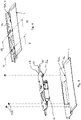
- Fig. 1 schematically shows parts of a roof closure assembly for a fixed roof of a vehicle (not shown).
- a frame 1 of the roof closure assembly may be attached to the lower or upper side of the fixed roof having a roof opening to be opened or closed by the closure, and the frame 1 then only having a passage opening 2 below the roof opening.
- Fig. 1 shows the frame 1 having two passage openings 2 and 3.
- the closure or closures to close these openings 2, 3 may for example be rigid, at least partly transparent panels 4, 5 (shown schematically by dotted lines), for example from glass or plastic.
- the front panel 4 may be a panel that is movable between a closed position closing the roof opening and an open position opening the opening at least partly, for example by tilting it to a venting position, and/or by sliding it rearwardly above the rear panel 5.
- the rear panel 5 may also be movable, or may be fixed in its position closing the rear passage opening 3.
- FIG. 1 An operating device for the front panel 4 is shown in assembled condition in Fig. 1 and includes a drive motor 6, two elongate connecting members 7, 8, here two drive cables fitted in guide tubes, two movable support mechanisms 9, 10, each movably supporting panel 4 at a side edge thereof, and two guide rails 11, 12 extending on opposite side edges of the roof opening 4 and slidably supporting the respective support mechanisms 9, 10. As is shown in Fig. 1 , all these parts are mounted to the frame 1 from above, and thus mainly on the upper side of frame 1.
- Fig. 2 , 3 and 4 show how drive motor 6 is mounted to frame 1, in this case to a front beam of frame 1. It is mounted to the front beam of frame 1 through a motor support 13, here a plate-shaped motor support 13 which is bolted to frame 1 by bolts 12a fixed to frame 1 and nuts 12b clamping motor support 13 to frame 1. Vibration isolating members 26 may be positioned between motor support 13 and frame 1 to isolate vibrations from drive motor 6 to frame 1.
- Drive motor 6 is mounted to the lower side of motor support 13.
- Frame 1 is provided with a vertical through-hole 14. When motor support 13 and drive motor 6 are in their mounted position, drive motor 6 projects through through-hole 14 which is thus of sufficient dimensions, i.e. larger than the vertical projection of the drive motor 6 with integrated gearbox to allow passage of drive motor 6.
- drive motor 6 is positioned completely or almost completely below through-hole 14 and only a drive gear wheel 15 of drive motor 6 is positioned above through-hole 14, so that connecting members 7, 8 may extend in a straight line above frame 1 (here in a depression 16 of frame 1) while being in engagement with drive gear wheel 15 of drive motor 6 positioned substantially below frame 1.
- drive motor 6 is positioned within or above through-hole 14.
- the function of through-hole 14 is to allow drive motor 6 to be serviced during the lifetime of the vehicle, which can only be done from the compartment of the vehicle, i.e. from below frame 1.
- motor support 13 and the through-hole 14 are used to obtain this combination of qualities.
- frame 1 and drive motor 6 are covered by a removable lining, panel or the like.
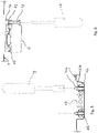
- Fig. 5 illustrates that motor support is mounted by fixing means that are accessible from above by means of a tool 19.
- Fig. 2 - 4 show guide tubes 20, 21 to guide elongate connecting members 7, 8. These guide tubes 20, 21 are only interrupted at the position of gear wheel 15 of drive motor 6, so that connecting members 7, 8, which have a tooting on their outer surface, can come into engagement with gear wheel 15 such that they are moved along their longitudinal axes to drive respective support mechanisms 9, 10 in order to move panel 4.
- a guide member 22 is used to keep connecting members 7, 8 in engagement with gear wheel 15 (see also Fig. 6 ) and a mounting member 23 fixes guide member 22 in position and aligns the guide tubes 20, 21 together with depressions on the lower side of motor support 13.
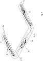
- Fig. 7 illustrates that a fixture 24 can be used to make a pre-assembly 25 of the operating device including drive motor 6, motor support 13, connecting members 7, 8, support mechanisms 9, 10 and guide rails 11, 12. All these parts are fixed in the correct relative position (when not already done by their fastening members) by fixture 24 and can be mounted as a pre-assembly to frame 1. It is then possible to remove fixture 24 and use it again for another closure roof assembly, although it is conceivable that a fixture is used that remains permanently fixed to frame 1. Such fixture then functions as a sub-frame. It will then be positioned below the operating device, not above as is shown in the removable version of Fig. 7 . Due to this fixture the mounting time in the main production line is minimised and many manipulations can be performed outside the main production line in parallel, which increases production capacity.
- the drive motor 6 is normally provided with a socket for an electric plug of wire cables of the electric and electronic control system of the vehicle and this plug will be plugged in the socket of electric drive motor 6 if it is mounted to the frame and is accessible from below frame 1 where the cable wire plug will temporarily be positioned before the roof closure assembly is mounted to the vehicle.
- the through-hole in the frame may remain partly open, or may be covered completely by the motor support.
- the invention is useful for all type of roofs, such as roofs with rigid panels (spoiler roofs, sliding roofs, tilt-sliding roofs etc.), folding roofs, slatted roofs and the like.
- the motor may be placed in any position, such as a front or rear beam, a centre beam if available.
- One or a plurality of drive motors may be attached to a single motor support and may be positioned in line with one through-hole or a plurality of through-holes.
- the guide tubes for the elongate connecting members may be replaced by guide channels formed in frame 1, which is especially suitable with a plastic injection moulded frame where the guide channels can easily be integrated.
Landscapes
- Engineering & Computer Science (AREA)
- Mechanical Engineering (AREA)
- Power-Operated Mechanisms For Wings (AREA)
- Body Structure For Vehicles (AREA)
- Seal Device For Vehicle (AREA)
- Sealing Battery Cases Or Jackets (AREA)
Description
- The invention relates to a roof closure assembly for a vehicle having an opening in its fixed vehicle roof.
- In some types of roof closure assemblies known today, parts of the assembly are mounted to the upper side of the frame, others to the lower side. The movable support mechanism for the closure and its guide rail must of course be mounted on the upper side of the frame. The drive motor, however, is mounted to the lower side of the frame as this part must be accessible for servicing, and this can only be done from below. As a result, the elongate connecting member extends partly below and partly above the frame and must therefore be threaded through the frame which is undesirable as it makes assembling more difficult and poses a leakage risk as the connecting member often extends in a so-called wet portion of the frame used for draining water to a drain outlet.
-
DE 40 14 487 C1 discloses a roof closure assembly according to the preamble ofclaim 1. The connecting members and possibly the drive motor are attached to the lower side of a holding plate which is an integral part of the frame. The connecting members extend to the upper side of the guide rails, thus extending partly above and partly below the frame. - It is one of the objects of the present invention to provide a roof closure assembly in which the disadvantages described above are removed or at least reduced.
- To obtain these and other objects, the roof closure assembly comprises the features of
claim 1. - By mounting the motor support, the connecting member and the movable support mechanism all to the upper side of the frame, no threading of the connecting member through the frame is necessary anymore, which is favourable. Furthermore, it is not required anymore during production to turn the frame 180 degrees to mount some parts to the upper and some parts to the lower side of the frame. Furthermore, in roof closure assemblies having one drive motor, there is only a single through-hole required for the drive motor, instead of two through-holes for the two connecting members that are generally being used. It is also easy to position the drive motor and thus the vertical through-hole outside the wet portions for drain water of a water management system of the frame thereby avoiding any leakage risk. Even if the through-hole is in the wet portion, it is easier to seal it, for example by sealing means connected to the motor support.
- Due to the vertical through-hole, the drive motor remains accessible from below which is important for servicing it. If the motor is mounted to the motor support by means of fastening members which are accessible from below after the motor support with its drive motor is mounted to the frame, it is possible to demount the drive motor and also remove it easily.
- The motor support may be a plate-shaped motor support to keep the building height as low as possible.
- The through-hole is of such dimensions that the drive motor can either be mounted to the motor support such that it extends at least partly below the through-hole if there is sufficient room below the frame, or it can be removed from the motor support through the through-hole for servicing during use.
- To facilitate mounting the motor support to the frame, the frame may be provided with pre-mounted screw bolts projecting upwardly from the frame and the motor support comprising aligning holes, the motor support being mounted by nuts fitting with the screw bolts. Of course, it is also possible to provide the frame with nuts, for example to integrate them in a plastic frame, and to fix the motor support by bolts screwed into the nuts.
- An output gearwheel of a gearbox integrated with the drive motor may project upwardly, the elongated connecting member being a toothed drive cable guided along a circumference of the output gearwheel and being in engagement with it, and extending in a tube or channel away from the gearwheel.
- The motor support may be mounted to the frame with interposition of one or more additional vibration isolating members to prevent any vibrations of the drive motor to be picked up and possibly be amplified by the frame.
- The invention also includes a method of assembling a roof closure assembly for a vehicle roof.
- The method according to the invention comprises the features of claim 9.
- Assembling is further facilitated if the method also comprises: pre-mounting the motor support and motor, the connecting member and optionally also the movable support mechanism and the guide rail into a pre-assembly that is subsequently mounted to the frame. This pre-mounting can be done on a separate sub-assembly line parallel to mounting operations on the frame, and the time required to mount the pre-assembly to the frame can be shorter than mounting parts separately to the frame, especially if the pre-assembly also includes the guide rail, and if the pre-assembly is mounted to a fixture before it is mounted to the frame.
- In the latter case, settings and adjustments can be made before mounting the pre-assembly to the frame thereby further reducing production time in the main production line.
- The fixture may be removed and reused after mounting the sub-assembly to the frame, so that no additional parts on the frame are used.
- The invention will further be elucidated with reference to the accompanying drawings showing an embodiment of the roof closure assembly by way of example.
-
Fig. 1 is a schematic perspective exploded view of a roof closure frame and operating device for a roof closure assembly. -
Fig. 2 is an exploded view of the parts in detail II inFig. 1 . -
Fig. 3 is a view corresponding to that ofFig. 2 , but showing the parts of the operating device in assembled condition. -
Fig. 4 is a view corresponding to that ofFig. 3 , but showing all parts assembled to the frame. -
Figs. 5 and 6 are sectional views according to the lines V-V and VI-VI, respectively, together with tools in dotted lines for mounting the motor support and for demounting the drive motor. -
Fig. 7 is a view corresponding to that ofFig. 1 , but illustrating the assembly of the operating device to the frame by means of a fixture. -
Fig. 1 schematically shows parts of a roof closure assembly for a fixed roof of a vehicle (not shown). Aframe 1 of the roof closure assembly may be attached to the lower or upper side of the fixed roof having a roof opening to be opened or closed by the closure, and theframe 1 then only having a passage opening 2 below the roof opening.Fig. 1 shows theframe 1 having two passage openings 2 and 3. The closure or closures to close these openings 2, 3 may for example be rigid, at least partly transparent panels 4, 5 (shown schematically by dotted lines), for example from glass or plastic. For example, the front panel 4 may be a panel that is movable between a closed position closing the roof opening and an open position opening the opening at least partly, for example by tilting it to a venting position, and/or by sliding it rearwardly above the rear panel 5. The rear panel 5 may also be movable, or may be fixed in its position closing the rear passage opening 3. - An operating device for the front panel 4 is shown in assembled condition in
Fig. 1 and includes adrive motor 6, two elongate connecting members 7, 8, here two drive cables fitted in guide tubes, two movable support mechanisms 9, 10, each movably supporting panel 4 at a side edge thereof, and twoguide rails Fig. 1 , all these parts are mounted to theframe 1 from above, and thus mainly on the upper side offrame 1. -
Fig. 2 ,3 and 4 show howdrive motor 6 is mounted toframe 1, in this case to a front beam offrame 1. It is mounted to the front beam offrame 1 through amotor support 13, here a plate-shaped motor support 13 which is bolted toframe 1 bybolts 12a fixed toframe 1 and nuts 12bclamping motor support 13 toframe 1.Vibration isolating members 26 may be positioned betweenmotor support 13 andframe 1 to isolate vibrations from drivemotor 6 toframe 1.Drive motor 6 is mounted to the lower side ofmotor support 13.Frame 1 is provided with a vertical through-hole 14. When motor support 13 anddrive motor 6 are in their mounted position, drivemotor 6 projects through through-hole 14 which is thus of sufficient dimensions, i.e. larger than the vertical projection of thedrive motor 6 with integrated gearbox to allow passage ofdrive motor 6. - As is shown in
Figs. 4 and6 ,drive motor 6 is positioned completely or almost completely below through-hole 14 and only adrive gear wheel 15 ofdrive motor 6 is positioned above through-hole 14, so that connecting members 7, 8 may extend in a straight line above frame 1 (here in adepression 16 of frame 1) while being in engagement withdrive gear wheel 15 ofdrive motor 6 positioned substantially belowframe 1. - In principle it is possible that
drive motor 6 is positioned within or above through-hole 14. The function of through-hole 14 is to allowdrive motor 6 to be serviced during the lifetime of the vehicle, which can only be done from the compartment of the vehicle, i.e. frombelow frame 1. Thus, to allow mounting the operating device to be mounted from above and to allow servicing of drive motor from below,motor support 13 and the through-hole 14 are used to obtain this combination of qualities. To allow demounting ofdrive motor 6, it is mounted tomotor support 13 bybolts 17 which are accessible by a tool 18 (seeFig. 6 ) from below. Of course, duringuse frame 1 and drivemotor 6 are covered by a removable lining, panel or the like. -
Fig. 5 illustrates that motor support is mounted by fixing means that are accessible from above by means of atool 19. -
Fig. 2 - 4 show guide tubes guide tubes gear wheel 15 ofdrive motor 6, so that connecting members 7, 8, which have a tooting on their outer surface, can come into engagement withgear wheel 15 such that they are moved along their longitudinal axes to drive respective support mechanisms 9, 10 in order to move panel 4. - A
guide member 22 is used to keep connecting members 7, 8 in engagement with gear wheel 15 (see alsoFig. 6 ) and amounting member 23fixes guide member 22 in position and aligns theguide tubes motor support 13. -
Fig. 7 illustrates that afixture 24 can be used to make a pre-assembly 25 of the operating device includingdrive motor 6,motor support 13, connecting members 7, 8, support mechanisms 9, 10 andguide rails fixture 24 and can be mounted as a pre-assembly to frame 1. It is then possible to removefixture 24 and use it again for another closure roof assembly, although it is conceivable that a fixture is used that remains permanently fixed toframe 1. Such fixture then functions as a sub-frame. It will then be positioned below the operating device, not above as is shown in the removable version ofFig. 7 . Due to this fixture the mounting time in the main production line is minimised and many manipulations can be performed outside the main production line in parallel, which increases production capacity. - The
drive motor 6 is normally provided with a socket for an electric plug of wire cables of the electric and electronic control system of the vehicle and this plug will be plugged in the socket ofelectric drive motor 6 if it is mounted to the frame and is accessible from belowframe 1 where the cable wire plug will temporarily be positioned before the roof closure assembly is mounted to the vehicle. - The invention is not limited to the embodiments described above and shown in the drawings, which may be varied in different manners within the scope of the appended claims.
- For example, the through-hole in the frame may remain partly open, or may be covered completely by the motor support. The invention is useful for all type of roofs, such as roofs with rigid panels (spoiler roofs, sliding roofs, tilt-sliding roofs etc.), folding roofs, slatted roofs and the like. The motor may be placed in any position, such as a front or rear beam, a centre beam if available. One or a plurality of drive motors may be attached to a single motor support and may be positioned in line with one through-hole or a plurality of through-holes. The guide tubes for the elongate connecting members may be replaced by guide channels formed in
frame 1, which is especially suitable with a plastic injection moulded frame where the guide channels can easily be integrated.
Claims (14)
- A roof closure assembly for a vehicle having an opening in its fixed vehicle roof, comprising:a frame (1) configured to be fixed to the vehicle roof and having an upper and lower side, the frame including a passage opening (2) positioned in use below the roof opening,a movable closure (4) for the roof opening,an operating device (6 - 12) on the frame movably supporting the closure, said operating device including at least one drive motor (6), at least a guide rail (11, 12) including a movable support mechanism (9, 10) for the closure and an elongate connecting member (7, 8) attached to the movable support mechanism and in engagement with the drive motor to enable the drive motor to drive the closure to move between a closed position closing the roof opening and an open position opening the roof opening at least partly,wherein the drive motor (6) is mounted to a lower side of a motor support (13),characterized in that the frame comprises a through-hole (14) providing communication between the upper and lower side of the frame (1), and wherein the motor support (13) with the motor (6) attached to its lower side in line with the through-hole (14) and the connecting member (7, 8) are mounted to the upper side of the frame, the through-hole (14) being larger than the vertical projection of the drive motor (6) with integrated gearbox such that the drive motor (6) is accessible through the through-hole (14).
- The roof closure assembly of claim 1, wherein the motor support (13) is a plate-shaped motor support.
- The roof closure assembly of claim 1 or 2, wherein the through-hole (14) is of such dimensions that the drive motor (6) can be mounted or removed from the motor support (13) through the through-hole (14).
- The roof closure assembly of claim 3, wherein the drive motor (6) extends at least partly below the through-hole (14) in the frame (1).
- The roof closure assembly of any of the preceding claim, wherein the drive motor (6) is mounted to the motor support (13) by one or more fastening members which are accessible through the through-hole in the frame.
- The roof closure assembly of any of the preceding claims, wherein an output gearwheel (15) of a gearbox integrated with the drive motor (6) projects upwardly, the elongated connecting member (7, 8) being a toothed drive cable guided along a circumference of the output gearwheel and being in engagement with it, and extending in a tube or channel (20, 21) away from the gearwheel.
- The roof closure assembly of any of the preceding claims, wherein the frame (1) is provided with a water management system including wet portions reachable for drain water, and wherein the motor support (13) is positioned outside the wet portions of the water management system.
- The roof closure assembly of any of the preceding claims, wherein the motor support (13) is mounted to the frame with interposition of one or more vibration isolating members (26).
- A method of assembling a roof closure assembly for a vehicle roof, said roof closure assembly comprising a frame (1) having an upper and lower side, a movable closure (4) for a roof opening, supported by the frame through a movable support mechanism (9, 10), and an operating device (6 - 12) including at least one drive motor (6), at least a guide rail (11, 12) including the movable support mechanism for the closure and an elongate connecting member (7, 8) attached to the movable support mechanism and in engagement with the drive motor enabling the closure to move between a closed position closing the roof opening (2) and an open position opening the roof opening at least partly, wherein the frame is provided with a through-hole (14) providing communication between the upper and lower side of the frame, said method comprising:- mounting the drive motor (6) to a lower side of a motor support (13),- mounting the motor support (13) with the motor (6) attached to its lower side in line with the through-hole (14) in the frame, the connecting member (7, 8) and the movable support mechanism (9, 10)to the upper side of the frame (1).
- The method of claim 9, and further comprising: pre-mounting the motor support (13) and motor (6), the connecting member (7, 8) and optionally also the movable support mechanism (9, 10) into a pre-assembly that is subsequently mounted to the frame (1) .
- The method of claim 10, wherein the pre-assembly also includes the guide rail (11, 12).
- The method of claim 10 or 11, further comprising mounting the motor support (13) and the motor (6), the connecting member (7, 8) and optionally the guide rail (11, 12) and movable support mechanism (9, 10) as the pre-assembly to a fixture (24)before it is mounted to the frame (1).
- The method of claim 12, comprising removing and reusing the fixture (24) after mounting the pre-assembly to the frame.
- The method of any of the preceding claims 9 - 13, comprising mounting the motor (6) to the motor support (13) by means of fastening members (17) which are accessible from below after the motor support and drive motor are mounted to the frame (1).
Priority Applications (4)
| Application Number | Priority Date | Filing Date | Title |
|---|---|---|---|
| ES16200972T ES2742837T5 (en) | 2016-11-28 | 2016-11-28 | roof closure assembly |
| EP16200972.4A EP3326851B2 (en) | 2016-11-28 | 2016-11-28 | Roof closure assembly |
| CN201711010432.0A CN108116208B (en) | 2016-11-28 | 2017-10-26 | Roof closure assembly and method of assembling a roof closure assembly |
| US15/816,284 US10322623B2 (en) | 2016-11-28 | 2017-11-17 | Roof closure assembly |
Applications Claiming Priority (1)
| Application Number | Priority Date | Filing Date | Title |
|---|---|---|---|
| EP16200972.4A EP3326851B2 (en) | 2016-11-28 | 2016-11-28 | Roof closure assembly |
Publications (3)
| Publication Number | Publication Date |
|---|---|
| EP3326851A1 EP3326851A1 (en) | 2018-05-30 |
| EP3326851B1 EP3326851B1 (en) | 2019-06-05 |
| EP3326851B2 true EP3326851B2 (en) | 2022-06-22 |
Family
ID=57406177
Family Applications (1)
| Application Number | Title | Priority Date | Filing Date |
|---|---|---|---|
| EP16200972.4A Active EP3326851B2 (en) | 2016-11-28 | 2016-11-28 | Roof closure assembly |
Country Status (4)
| Country | Link |
|---|---|
| US (1) | US10322623B2 (en) |
| EP (1) | EP3326851B2 (en) |
| CN (1) | CN108116208B (en) |
| ES (1) | ES2742837T5 (en) |
Families Citing this family (4)
| Publication number | Priority date | Publication date | Assignee | Title |
|---|---|---|---|---|
| DE102019004227A1 (en) * | 2019-06-13 | 2020-12-17 | Man Truck & Bus Se | Device for interior ventilation for a motor vehicle |
| EP3792091B1 (en) | 2019-09-10 | 2022-06-15 | Inalfa Roof Systems Group B.V. | Roof assembly for a vehicle and a method of assembling |
| EP3868992B1 (en) * | 2020-02-19 | 2024-10-09 | Inalfa Roof Systems Group B.V. | Open roof assembly for use in a vehicle and a method for operating same |
| EP4019307B1 (en) * | 2020-12-24 | 2024-05-01 | Inalfa Roof Systems Group B.V. | Central pop-up gearbox on standard platform motor |
Citations (1)
| Publication number | Priority date | Publication date | Assignee | Title |
|---|---|---|---|---|
| JPH0678039U (en) † | 1993-04-16 | 1994-11-01 | ダイキョー・ベバスト株式会社 | Mounting structure for movable roof panel drive |
Family Cites Families (31)
| Publication number | Priority date | Publication date | Assignee | Title |
|---|---|---|---|---|
| US3874722A (en) * | 1973-03-20 | 1975-04-01 | Ferro Mfg Corp | Sun roof gear box |
| DE2914855C2 (en) | 1979-04-12 | 1983-01-05 | Webasto-Werk W. Baier GmbH & Co, 8035 Gauting | Vehicle roof |
| DE3002246C2 (en) | 1980-01-23 | 1984-11-29 | Webasto-Werk W. Baier GmbH & Co, 8035 Gauting | Motor vehicle roof |
| JPS5824288B2 (en) * | 1980-08-15 | 1983-05-20 | マツダ株式会社 | Body roof structure of vehicles equipped with sliding grooves and its assembly method |
| JPS5830830A (en) * | 1981-08-13 | 1983-02-23 | Aisin Seiki Co Ltd | Driver for sun roof |
| JPH0777849B2 (en) | 1986-08-29 | 1995-08-23 | マツダ株式会社 | Vehicle bus stop |
| DE3832681C1 (en) | 1988-09-27 | 1989-10-26 | Webasto Ag Fahrzeugtechnik, 8035 Gauting, De | |
| JPH0370627A (en) | 1989-08-11 | 1991-03-26 | Mazda Motor Corp | Slide roof device for vehicle |
| DE4012635A1 (en) * | 1990-04-20 | 1991-10-24 | Webasto Ag Fahrzeugtechnik | Road vehicle roof arrangement - involves sliding roof in frame made of injection-moulded plastics, with reinforcement plates in high load areas |
| DE4014487C1 (en) | 1990-05-07 | 1991-08-14 | Webasto Ag Fahrzeugtechnik, 8035 Stockdorf, De | |
| DE9101213U1 (en) | 1991-02-02 | 1991-04-25 | Webasto AG Fahrzeugtechnik, 8035 Stockdorf | Sunroof or sliding/tilting roof for vehicles |
| US6129413A (en) | 1997-11-13 | 2000-10-10 | Asc Incorporated | Powered dual panel sunroof |
| JPH11240333A (en) | 1998-02-23 | 1999-09-07 | Yachiyo Industry Co Ltd | Sunroof equipment |
| DE10046674C2 (en) | 2000-07-06 | 2003-03-27 | Webasto Vehicle Sys Int Gmbh | Vehicle roof module |
| DE10146284C2 (en) | 2001-09-19 | 2003-11-13 | Webasto Vehicle Sys Int Gmbh | Openable vehicle roof |
| DE20122831U1 (en) | 2001-12-28 | 2008-06-12 | Webasto Ag | Openable vehicle roof with drive cables |
| DE202004015344U1 (en) | 2004-07-15 | 2005-11-24 | Daimlerchrysler Ag | Automobile door has inner module with supporting structure with strengthening frame that is joined to plastic base support to form hybrid part that simultaneously forms supporting surface of inner door cladding |
| DE102004050107B4 (en) | 2004-10-14 | 2008-08-21 | Webasto Ag | vehicle roof |
| JP4504797B2 (en) * | 2004-12-16 | 2010-07-14 | 八千代工業株式会社 | Mounting structure of drive motor unit in sunroof device |
| DE202005016483U1 (en) | 2005-10-20 | 2006-01-12 | Webasto Ag | Sunroof actuating device for motor vehicle, has motor, holding body and guiding pipes that are connected to each other and to framework using connecting units such as screw and nut |
| DE202005018138U1 (en) | 2005-11-17 | 2006-04-13 | Webasto Ag | Cable guide esp. for motor vehicle sun-roof, has guide tube running between drive and guide channel |
| JP2008037229A (en) * | 2006-08-04 | 2008-02-21 | Yachiyo Industry Co Ltd | Guide frame mounting structure for sunroof equipment |
| JP5207618B2 (en) * | 2006-11-17 | 2013-06-12 | ベバスト ジャパン株式会社 | Drive device |
| US7527328B2 (en) * | 2007-05-24 | 2009-05-05 | Specialty Vehicle Acquisition Corp. | Modular roof system for automotive vehicle |
| JP5185693B2 (en) | 2008-05-23 | 2013-04-17 | 八千代工業株式会社 | Bracket structure of drive motor in sunroof device |
| US7905542B2 (en) | 2009-06-23 | 2011-03-15 | Webasto Ag | Modular tilt slide sunroof assembly and method of manufacture |
| DE202010003687U1 (en) | 2010-03-16 | 2010-07-15 | Webasto Ag | Mounting frame for a movable vehicle body part |
| FR2960477B1 (en) | 2010-05-26 | 2012-06-08 | Webasto Systemes Carrosserie | SUPPORT DEVICE FOR MOTOR ORGAN |
| JP5790221B2 (en) * | 2011-07-12 | 2015-10-07 | アイシン精機株式会社 | Vehicle roof device |
| JP5741269B2 (en) * | 2011-07-20 | 2015-07-01 | アイシン精機株式会社 | Vehicle roof device |
| US20160288631A1 (en) | 2015-03-31 | 2016-10-06 | GM Global Technology Operations LLC | Dual drive sunroof transmission assembly |
-
2016
- 2016-11-28 ES ES16200972T patent/ES2742837T5/en active Active
- 2016-11-28 EP EP16200972.4A patent/EP3326851B2/en active Active
-
2017
- 2017-10-26 CN CN201711010432.0A patent/CN108116208B/en active Active
- 2017-11-17 US US15/816,284 patent/US10322623B2/en active Active
Patent Citations (1)
| Publication number | Priority date | Publication date | Assignee | Title |
|---|---|---|---|---|
| JPH0678039U (en) † | 1993-04-16 | 1994-11-01 | ダイキョー・ベバスト株式会社 | Mounting structure for movable roof panel drive |
Also Published As
| Publication number | Publication date |
|---|---|
| ES2742837T5 (en) | 2022-10-03 |
| EP3326851A1 (en) | 2018-05-30 |
| US10322623B2 (en) | 2019-06-18 |
| US20180147921A1 (en) | 2018-05-31 |
| ES2742837T3 (en) | 2020-02-17 |
| CN108116208A (en) | 2018-06-05 |
| EP3326851B1 (en) | 2019-06-05 |
| CN108116208B (en) | 2023-05-02 |
Similar Documents
| Publication | Publication Date | Title |
|---|---|---|
| EP3326851B2 (en) | Roof closure assembly | |
| CN102431425B (en) | Sunroof device | |
| EP3020587B1 (en) | Method of mounting a roof panel assembly; as well as such roof panel assembly | |
| US7743559B2 (en) | Modular support for automobile doors, door assembly for an automobile and method for mounting the modular support on a door frame | |
| DE19802478A1 (en) | Door module with external rope window regulator | |
| CN104114414A (en) | Motor vehicle arrangement having a three-element water box | |
| US11498402B2 (en) | Sunroof unit | |
| DE10327839A1 (en) | Vehicle roof module | |
| US9796439B2 (en) | Method for coupling a sunroof glass apparatus to a vehicle body | |
| US10913336B2 (en) | Method for producing a vehicle roof, modular roof for a vehicle roof, and vehicle roof for a motor vehicle | |
| US20080148647A1 (en) | Adjustable Mounting Assembly | |
| JP6595203B2 (en) | Open roof structure for vehicles | |
| CN112549927B (en) | Roof assembly and assembly method for a vehicle | |
| DE102011076400A1 (en) | Window lifter carrier with crash sensor | |
| JP2004114927A (en) | Vehicle sunroof structure | |
| FI109004B (en) | Procedure and arrangement for mounting a door in a vehicle basket | |
| CN111469954A (en) | Assembly structure and assembly method of automobile skylight | |
| KR20120100286A (en) | Roof console of automotive headliner and method for assembling the same | |
| EP1099582B1 (en) | Open roof construction for a vehicle | |
| CN115122883A (en) | Roof assembly | |
| GB2591137A (en) | System for mounting a roof fairing to a roof of a vehicle | |
| DE202005016582U1 (en) | Aggregate support for e.g. sliding door, has support plates arranged in parallel along surface that is clamped by outer edge areas, where part of mounting- and/or bearing areas of support is provided at support | |
| GB2478649A (en) | Body shell for a motor vehicle front-section, and method for manufacturing the same |
Legal Events
| Date | Code | Title | Description |
|---|---|---|---|
| PUAI | Public reference made under article 153(3) epc to a published international application that has entered the european phase |
Free format text: ORIGINAL CODE: 0009012 |
|
| STAA | Information on the status of an ep patent application or granted ep patent |
Free format text: STATUS: THE APPLICATION HAS BEEN PUBLISHED |
|
| AK | Designated contracting states |
Kind code of ref document: A1 Designated state(s): AL AT BE BG CH CY CZ DE DK EE ES FI FR GB GR HR HU IE IS IT LI LT LU LV MC MK MT NL NO PL PT RO RS SE SI SK SM TR |
|
| AX | Request for extension of the european patent |
Extension state: BA ME |
|
| STAA | Information on the status of an ep patent application or granted ep patent |
Free format text: STATUS: REQUEST FOR EXAMINATION WAS MADE |
|
| 17P | Request for examination filed |
Effective date: 20181115 |
|
| RBV | Designated contracting states (corrected) |
Designated state(s): AL AT BE BG CH CY CZ DE DK EE ES FI FR GB GR HR HU IE IS IT LI LT LU LV MC MK MT NL NO PL PT RO RS SE SI SK SM TR |
|
| GRAP | Despatch of communication of intention to grant a patent |
Free format text: ORIGINAL CODE: EPIDOSNIGR1 |
|
| STAA | Information on the status of an ep patent application or granted ep patent |
Free format text: STATUS: GRANT OF PATENT IS INTENDED |
|
| INTG | Intention to grant announced |
Effective date: 20190320 |
|
| RIN1 | Information on inventor provided before grant (corrected) |
Inventor name: NELLEN, MARCEL JOHAN CHRISTIAAN Inventor name: LAND, FRIJKE IRENE |
|
| GRAS | Grant fee paid |
Free format text: ORIGINAL CODE: EPIDOSNIGR3 |
|
| GRAA | (expected) grant |
Free format text: ORIGINAL CODE: 0009210 |
|
| STAA | Information on the status of an ep patent application or granted ep patent |
Free format text: STATUS: THE PATENT HAS BEEN GRANTED |
|
| AK | Designated contracting states |
Kind code of ref document: B1 Designated state(s): AL AT BE BG CH CY CZ DE DK EE ES FI FR GB GR HR HU IE IS IT LI LT LU LV MC MK MT NL NO PL PT RO RS SE SI SK SM TR |
|
| REG | Reference to a national code |
Ref country code: GB Ref legal event code: FG4D |
|
| REG | Reference to a national code |
Ref country code: CH Ref legal event code: EP |
|
| REG | Reference to a national code |
Ref country code: AT Ref legal event code: REF Ref document number: 1139629 Country of ref document: AT Kind code of ref document: T Effective date: 20190615 |
|
| REG | Reference to a national code |
Ref country code: IE Ref legal event code: FG4D |
|
| REG | Reference to a national code |
Ref country code: DE Ref legal event code: R096 Ref document number: 602016014762 Country of ref document: DE |
|
| REG | Reference to a national code |
Ref country code: NL Ref legal event code: MP Effective date: 20190605 |
|
| REG | Reference to a national code |
Ref country code: LT Ref legal event code: MG4D |
|
| PG25 | Lapsed in a contracting state [announced via postgrant information from national office to epo] |
Ref country code: HR Free format text: LAPSE BECAUSE OF FAILURE TO SUBMIT A TRANSLATION OF THE DESCRIPTION OR TO PAY THE FEE WITHIN THE PRESCRIBED TIME-LIMIT Effective date: 20190605 Ref country code: LT Free format text: LAPSE BECAUSE OF FAILURE TO SUBMIT A TRANSLATION OF THE DESCRIPTION OR TO PAY THE FEE WITHIN THE PRESCRIBED TIME-LIMIT Effective date: 20190605 Ref country code: NO Free format text: LAPSE BECAUSE OF FAILURE TO SUBMIT A TRANSLATION OF THE DESCRIPTION OR TO PAY THE FEE WITHIN THE PRESCRIBED TIME-LIMIT Effective date: 20190905 Ref country code: FI Free format text: LAPSE BECAUSE OF FAILURE TO SUBMIT A TRANSLATION OF THE DESCRIPTION OR TO PAY THE FEE WITHIN THE PRESCRIBED TIME-LIMIT Effective date: 20190605 Ref country code: SE Free format text: LAPSE BECAUSE OF FAILURE TO SUBMIT A TRANSLATION OF THE DESCRIPTION OR TO PAY THE FEE WITHIN THE PRESCRIBED TIME-LIMIT Effective date: 20190605 Ref country code: AL Free format text: LAPSE BECAUSE OF FAILURE TO SUBMIT A TRANSLATION OF THE DESCRIPTION OR TO PAY THE FEE WITHIN THE PRESCRIBED TIME-LIMIT Effective date: 20190605 |
|
| PG25 | Lapsed in a contracting state [announced via postgrant information from national office to epo] |
Ref country code: LV Free format text: LAPSE BECAUSE OF FAILURE TO SUBMIT A TRANSLATION OF THE DESCRIPTION OR TO PAY THE FEE WITHIN THE PRESCRIBED TIME-LIMIT Effective date: 20190605 Ref country code: BG Free format text: LAPSE BECAUSE OF FAILURE TO SUBMIT A TRANSLATION OF THE DESCRIPTION OR TO PAY THE FEE WITHIN THE PRESCRIBED TIME-LIMIT Effective date: 20190905 Ref country code: GR Free format text: LAPSE BECAUSE OF FAILURE TO SUBMIT A TRANSLATION OF THE DESCRIPTION OR TO PAY THE FEE WITHIN THE PRESCRIBED TIME-LIMIT Effective date: 20190906 Ref country code: RS Free format text: LAPSE BECAUSE OF FAILURE TO SUBMIT A TRANSLATION OF THE DESCRIPTION OR TO PAY THE FEE WITHIN THE PRESCRIBED TIME-LIMIT Effective date: 20190605 |
|
| REG | Reference to a national code |
Ref country code: AT Ref legal event code: MK05 Ref document number: 1139629 Country of ref document: AT Kind code of ref document: T Effective date: 20190605 |
|
| PG25 | Lapsed in a contracting state [announced via postgrant information from national office to epo] |
Ref country code: CZ Free format text: LAPSE BECAUSE OF FAILURE TO SUBMIT A TRANSLATION OF THE DESCRIPTION OR TO PAY THE FEE WITHIN THE PRESCRIBED TIME-LIMIT Effective date: 20190605 Ref country code: RO Free format text: LAPSE BECAUSE OF FAILURE TO SUBMIT A TRANSLATION OF THE DESCRIPTION OR TO PAY THE FEE WITHIN THE PRESCRIBED TIME-LIMIT Effective date: 20190605 Ref country code: PT Free format text: LAPSE BECAUSE OF FAILURE TO SUBMIT A TRANSLATION OF THE DESCRIPTION OR TO PAY THE FEE WITHIN THE PRESCRIBED TIME-LIMIT Effective date: 20191007 Ref country code: EE Free format text: LAPSE BECAUSE OF FAILURE TO SUBMIT A TRANSLATION OF THE DESCRIPTION OR TO PAY THE FEE WITHIN THE PRESCRIBED TIME-LIMIT Effective date: 20190605 Ref country code: NL Free format text: LAPSE BECAUSE OF FAILURE TO SUBMIT A TRANSLATION OF THE DESCRIPTION OR TO PAY THE FEE WITHIN THE PRESCRIBED TIME-LIMIT Effective date: 20190605 Ref country code: SK Free format text: LAPSE BECAUSE OF FAILURE TO SUBMIT A TRANSLATION OF THE DESCRIPTION OR TO PAY THE FEE WITHIN THE PRESCRIBED TIME-LIMIT Effective date: 20190605 Ref country code: AT Free format text: LAPSE BECAUSE OF FAILURE TO SUBMIT A TRANSLATION OF THE DESCRIPTION OR TO PAY THE FEE WITHIN THE PRESCRIBED TIME-LIMIT Effective date: 20190605 |
|
| REG | Reference to a national code |
Ref country code: ES Ref legal event code: FG2A Ref document number: 2742837 Country of ref document: ES Kind code of ref document: T3 Effective date: 20200217 |
|
| PG25 | Lapsed in a contracting state [announced via postgrant information from national office to epo] |
Ref country code: IT Free format text: LAPSE BECAUSE OF FAILURE TO SUBMIT A TRANSLATION OF THE DESCRIPTION OR TO PAY THE FEE WITHIN THE PRESCRIBED TIME-LIMIT Effective date: 20190605 Ref country code: SM Free format text: LAPSE BECAUSE OF FAILURE TO SUBMIT A TRANSLATION OF THE DESCRIPTION OR TO PAY THE FEE WITHIN THE PRESCRIBED TIME-LIMIT Effective date: 20190605 Ref country code: IS Free format text: LAPSE BECAUSE OF FAILURE TO SUBMIT A TRANSLATION OF THE DESCRIPTION OR TO PAY THE FEE WITHIN THE PRESCRIBED TIME-LIMIT Effective date: 20191005 |
|
| REG | Reference to a national code |
Ref country code: DE Ref legal event code: R026 Ref document number: 602016014762 Country of ref document: DE |
|
| PLBI | Opposition filed |
Free format text: ORIGINAL CODE: 0009260 |
|
| PG25 | Lapsed in a contracting state [announced via postgrant information from national office to epo] |
Ref country code: TR Free format text: LAPSE BECAUSE OF FAILURE TO SUBMIT A TRANSLATION OF THE DESCRIPTION OR TO PAY THE FEE WITHIN THE PRESCRIBED TIME-LIMIT Effective date: 20190605 |
|
| PLAX | Notice of opposition and request to file observation + time limit sent |
Free format text: ORIGINAL CODE: EPIDOSNOBS2 |
|
| 26 | Opposition filed |
Opponent name: WEBASTO SE Effective date: 20200304 |
|
| PG25 | Lapsed in a contracting state [announced via postgrant information from national office to epo] |
Ref country code: DK Free format text: LAPSE BECAUSE OF FAILURE TO SUBMIT A TRANSLATION OF THE DESCRIPTION OR TO PAY THE FEE WITHIN THE PRESCRIBED TIME-LIMIT Effective date: 20190605 Ref country code: PL Free format text: LAPSE BECAUSE OF FAILURE TO SUBMIT A TRANSLATION OF THE DESCRIPTION OR TO PAY THE FEE WITHIN THE PRESCRIBED TIME-LIMIT Effective date: 20190605 |
|
| PG25 | Lapsed in a contracting state [announced via postgrant information from national office to epo] |
Ref country code: SI Free format text: LAPSE BECAUSE OF FAILURE TO SUBMIT A TRANSLATION OF THE DESCRIPTION OR TO PAY THE FEE WITHIN THE PRESCRIBED TIME-LIMIT Effective date: 20190605 |
|
| REG | Reference to a national code |
Ref country code: CH Ref legal event code: PL |
|
| PG25 | Lapsed in a contracting state [announced via postgrant information from national office to epo] |
Ref country code: LU Free format text: LAPSE BECAUSE OF NON-PAYMENT OF DUE FEES Effective date: 20191128 Ref country code: MC Free format text: LAPSE BECAUSE OF FAILURE TO SUBMIT A TRANSLATION OF THE DESCRIPTION OR TO PAY THE FEE WITHIN THE PRESCRIBED TIME-LIMIT Effective date: 20190605 Ref country code: LI Free format text: LAPSE BECAUSE OF NON-PAYMENT OF DUE FEES Effective date: 20191130 Ref country code: CH Free format text: LAPSE BECAUSE OF NON-PAYMENT OF DUE FEES Effective date: 20191130 |
|
| PLBB | Reply of patent proprietor to notice(s) of opposition received |
Free format text: ORIGINAL CODE: EPIDOSNOBS3 |
|
| REG | Reference to a national code |
Ref country code: BE Ref legal event code: MM Effective date: 20191130 |
|
| PG25 | Lapsed in a contracting state [announced via postgrant information from national office to epo] |
Ref country code: IE Free format text: LAPSE BECAUSE OF NON-PAYMENT OF DUE FEES Effective date: 20191128 |
|
| PG25 | Lapsed in a contracting state [announced via postgrant information from national office to epo] |
Ref country code: BE Free format text: LAPSE BECAUSE OF NON-PAYMENT OF DUE FEES Effective date: 20191130 |
|
| PG25 | Lapsed in a contracting state [announced via postgrant information from national office to epo] |
Ref country code: CY Free format text: LAPSE BECAUSE OF FAILURE TO SUBMIT A TRANSLATION OF THE DESCRIPTION OR TO PAY THE FEE WITHIN THE PRESCRIBED TIME-LIMIT Effective date: 20190605 |
|
| PG25 | Lapsed in a contracting state [announced via postgrant information from national office to epo] |
Ref country code: MT Free format text: LAPSE BECAUSE OF FAILURE TO SUBMIT A TRANSLATION OF THE DESCRIPTION OR TO PAY THE FEE WITHIN THE PRESCRIBED TIME-LIMIT Effective date: 20190605 Ref country code: HU Free format text: LAPSE BECAUSE OF FAILURE TO SUBMIT A TRANSLATION OF THE DESCRIPTION OR TO PAY THE FEE WITHIN THE PRESCRIBED TIME-LIMIT; INVALID AB INITIO Effective date: 20161128 |
|
| APAH | Appeal reference modified |
Free format text: ORIGINAL CODE: EPIDOSCREFNO |
|
| APAW | Appeal reference deleted |
Free format text: ORIGINAL CODE: EPIDOSDREFNO |
|
| APBM | Appeal reference recorded |
Free format text: ORIGINAL CODE: EPIDOSNREFNO |
|
| APBP | Date of receipt of notice of appeal recorded |
Free format text: ORIGINAL CODE: EPIDOSNNOA2O |
|
| APBQ | Date of receipt of statement of grounds of appeal recorded |
Free format text: ORIGINAL CODE: EPIDOSNNOA3O |
|
| APBU | Appeal procedure closed |
Free format text: ORIGINAL CODE: EPIDOSNNOA9O |
|
| PUAH | Patent maintained in amended form |
Free format text: ORIGINAL CODE: 0009272 |
|
| STAA | Information on the status of an ep patent application or granted ep patent |
Free format text: STATUS: PATENT MAINTAINED AS AMENDED |
|
| 27A | Patent maintained in amended form |
Effective date: 20220622 |
|
| AK | Designated contracting states |
Kind code of ref document: B2 Designated state(s): AL AT BE BG CH CY CZ DE DK EE ES FI FR GB GR HR HU IE IS IT LI LT LU LV MC MK MT NL NO PL PT RO RS SE SI SK SM TR |
|
| REG | Reference to a national code |
Ref country code: DE Ref legal event code: R102 Ref document number: 602016014762 Country of ref document: DE |
|
| PG25 | Lapsed in a contracting state [announced via postgrant information from national office to epo] |
Ref country code: MK Free format text: LAPSE BECAUSE OF FAILURE TO SUBMIT A TRANSLATION OF THE DESCRIPTION OR TO PAY THE FEE WITHIN THE PRESCRIBED TIME-LIMIT Effective date: 20190605 |
|
| REG | Reference to a national code |
Ref country code: ES Ref legal event code: DC2A Ref document number: 2742837 Country of ref document: ES Kind code of ref document: T5 Effective date: 20221003 |
|
| PGFP | Annual fee paid to national office [announced via postgrant information from national office to epo] |
Ref country code: DE Payment date: 20251128 Year of fee payment: 10 |
|
| PGFP | Annual fee paid to national office [announced via postgrant information from national office to epo] |
Ref country code: GB Payment date: 20251127 Year of fee payment: 10 |
|
| PGFP | Annual fee paid to national office [announced via postgrant information from national office to epo] |
Ref country code: FR Payment date: 20251125 Year of fee payment: 10 |
|
| PGFP | Annual fee paid to national office [announced via postgrant information from national office to epo] |
Ref country code: ES Payment date: 20251201 Year of fee payment: 10 |