EP4019307B1 - Central pop-up gearbox on standard platform motor - Google Patents
Central pop-up gearbox on standard platform motor Download PDFInfo
- Publication number
- EP4019307B1 EP4019307B1 EP21207311.8A EP21207311A EP4019307B1 EP 4019307 B1 EP4019307 B1 EP 4019307B1 EP 21207311 A EP21207311 A EP 21207311A EP 4019307 B1 EP4019307 B1 EP 4019307B1
- Authority
- EP
- European Patent Office
- Prior art keywords
- roof construction
- open roof
- panel
- gearbox
- motor
- Prior art date
- Legal status (The legal status is an assumption and is not a legal conclusion. Google has not performed a legal analysis and makes no representation as to the accuracy of the status listed.)
- Active
Links
- 238000010276 construction Methods 0.000 claims description 40
- 230000000712 assembly Effects 0.000 claims description 26
- 238000000429 assembly Methods 0.000 claims description 26
- 238000013016 damping Methods 0.000 claims description 15
- 239000000463 material Substances 0.000 claims description 14
- 230000007246 mechanism Effects 0.000 description 12
- 230000005540 biological transmission Effects 0.000 description 4
- 238000002955 isolation Methods 0.000 description 2
- 238000005259 measurement Methods 0.000 description 2
- 239000004033 plastic Substances 0.000 description 2
- 229920003023 plastic Polymers 0.000 description 2
- 238000007789 sealing Methods 0.000 description 2
- 229910000831 Steel Inorganic materials 0.000 description 1
- 238000005452 bending Methods 0.000 description 1
- 230000000694 effects Effects 0.000 description 1
- 239000011521 glass Substances 0.000 description 1
- 239000003292 glue Substances 0.000 description 1
- 239000002184 metal Substances 0.000 description 1
- 238000000034 method Methods 0.000 description 1
- 238000004806 packaging method and process Methods 0.000 description 1
- 239000010959 steel Substances 0.000 description 1
- XLYOFNOQVPJJNP-UHFFFAOYSA-N water Substances O XLYOFNOQVPJJNP-UHFFFAOYSA-N 0.000 description 1
Images


Classifications
-
- F—MECHANICAL ENGINEERING; LIGHTING; HEATING; WEAPONS; BLASTING
- F16—ENGINEERING ELEMENTS AND UNITS; GENERAL MEASURES FOR PRODUCING AND MAINTAINING EFFECTIVE FUNCTIONING OF MACHINES OR INSTALLATIONS; THERMAL INSULATION IN GENERAL
- F16H—GEARING
- F16H57/00—General details of gearing
- F16H57/02—Gearboxes; Mounting gearing therein
-
- E—FIXED CONSTRUCTIONS
- E05—LOCKS; KEYS; WINDOW OR DOOR FITTINGS; SAFES
- E05F—DEVICES FOR MOVING WINGS INTO OPEN OR CLOSED POSITION; CHECKS FOR WINGS; WING FITTINGS NOT OTHERWISE PROVIDED FOR, CONCERNED WITH THE FUNCTIONING OF THE WING
- E05F15/00—Power-operated mechanisms for wings
- E05F15/60—Power-operated mechanisms for wings using electrical actuators
- E05F15/603—Power-operated mechanisms for wings using electrical actuators using rotary electromotors
- E05F15/632—Power-operated mechanisms for wings using electrical actuators using rotary electromotors for horizontally-sliding wings
- E05F15/649—Power-operated mechanisms for wings using electrical actuators using rotary electromotors for horizontally-sliding wings operated by swinging arms
-
- B—PERFORMING OPERATIONS; TRANSPORTING
- B60—VEHICLES IN GENERAL
- B60J—WINDOWS, WINDSCREENS, NON-FIXED ROOFS, DOORS, OR SIMILAR DEVICES FOR VEHICLES; REMOVABLE EXTERNAL PROTECTIVE COVERINGS SPECIALLY ADAPTED FOR VEHICLES
- B60J7/00—Non-fixed roofs; Roofs with movable panels, e.g. rotary sunroofs
- B60J7/02—Non-fixed roofs; Roofs with movable panels, e.g. rotary sunroofs of sliding type, e.g. comprising guide shoes
- B60J7/04—Non-fixed roofs; Roofs with movable panels, e.g. rotary sunroofs of sliding type, e.g. comprising guide shoes with rigid plate-like element or elements, e.g. open roofs with harmonica-type folding rigid panels
- B60J7/057—Driving or actuating arrangements e.g. manually operated levers or knobs
- B60J7/0573—Driving or actuating arrangements e.g. manually operated levers or knobs power driven arrangements, e.g. electrical
-
- B—PERFORMING OPERATIONS; TRANSPORTING
- B60—VEHICLES IN GENERAL
- B60J—WINDOWS, WINDSCREENS, NON-FIXED ROOFS, DOORS, OR SIMILAR DEVICES FOR VEHICLES; REMOVABLE EXTERNAL PROTECTIVE COVERINGS SPECIALLY ADAPTED FOR VEHICLES
- B60J7/00—Non-fixed roofs; Roofs with movable panels, e.g. rotary sunroofs
- B60J7/02—Non-fixed roofs; Roofs with movable panels, e.g. rotary sunroofs of sliding type, e.g. comprising guide shoes
- B60J7/04—Non-fixed roofs; Roofs with movable panels, e.g. rotary sunroofs of sliding type, e.g. comprising guide shoes with rigid plate-like element or elements, e.g. open roofs with harmonica-type folding rigid panels
- B60J7/043—Sunroofs e.g. sliding above the roof
-
- B—PERFORMING OPERATIONS; TRANSPORTING
- B60—VEHICLES IN GENERAL
- B60J—WINDOWS, WINDSCREENS, NON-FIXED ROOFS, DOORS, OR SIMILAR DEVICES FOR VEHICLES; REMOVABLE EXTERNAL PROTECTIVE COVERINGS SPECIALLY ADAPTED FOR VEHICLES
- B60J7/00—Non-fixed roofs; Roofs with movable panels, e.g. rotary sunroofs
- B60J7/08—Non-fixed roofs; Roofs with movable panels, e.g. rotary sunroofs of non-sliding type, i.e. movable or removable roofs or panels, e.g. let-down tops or roofs capable of being easily detached or of assuming a collapsed or inoperative position
- B60J7/16—Non-fixed roofs; Roofs with movable panels, e.g. rotary sunroofs of non-sliding type, i.e. movable or removable roofs or panels, e.g. let-down tops or roofs capable of being easily detached or of assuming a collapsed or inoperative position non-foldable and rigid, e.g. a one-piece hard-top or a single rigid roof panel
- B60J7/1628—Non-fixed roofs; Roofs with movable panels, e.g. rotary sunroofs of non-sliding type, i.e. movable or removable roofs or panels, e.g. let-down tops or roofs capable of being easily detached or of assuming a collapsed or inoperative position non-foldable and rigid, e.g. a one-piece hard-top or a single rigid roof panel for covering the passenger compartment
- B60J7/1635—Non-fixed roofs; Roofs with movable panels, e.g. rotary sunroofs of non-sliding type, i.e. movable or removable roofs or panels, e.g. let-down tops or roofs capable of being easily detached or of assuming a collapsed or inoperative position non-foldable and rigid, e.g. a one-piece hard-top or a single rigid roof panel for covering the passenger compartment of non-convertible vehicles
- B60J7/1642—Roof panels, e.g. sunroofs or hatches, movable relative to the main roof structure, e.g. by lifting or pivoting
-
- E—FIXED CONSTRUCTIONS
- E05—LOCKS; KEYS; WINDOW OR DOOR FITTINGS; SAFES
- E05F—DEVICES FOR MOVING WINGS INTO OPEN OR CLOSED POSITION; CHECKS FOR WINGS; WING FITTINGS NOT OTHERWISE PROVIDED FOR, CONCERNED WITH THE FUNCTIONING OF THE WING
- E05F15/00—Power-operated mechanisms for wings
- E05F15/60—Power-operated mechanisms for wings using electrical actuators
- E05F15/603—Power-operated mechanisms for wings using electrical actuators using rotary electromotors
- E05F15/632—Power-operated mechanisms for wings using electrical actuators using rotary electromotors for horizontally-sliding wings
- E05F15/655—Power-operated mechanisms for wings using electrical actuators using rotary electromotors for horizontally-sliding wings specially adapted for vehicle wings
- E05F15/662—Motor units therefor, e.g. geared motors
-
- E—FIXED CONSTRUCTIONS
- E05—LOCKS; KEYS; WINDOW OR DOOR FITTINGS; SAFES
- E05F—DEVICES FOR MOVING WINGS INTO OPEN OR CLOSED POSITION; CHECKS FOR WINGS; WING FITTINGS NOT OTHERWISE PROVIDED FOR, CONCERNED WITH THE FUNCTIONING OF THE WING
- E05F15/00—Power-operated mechanisms for wings
- E05F15/60—Power-operated mechanisms for wings using electrical actuators
- E05F15/603—Power-operated mechanisms for wings using electrical actuators using rotary electromotors
- E05F15/665—Power-operated mechanisms for wings using electrical actuators using rotary electromotors for vertically-sliding wings
- E05F15/689—Power-operated mechanisms for wings using electrical actuators using rotary electromotors for vertically-sliding wings specially adapted for vehicle windows
- E05F15/697—Motor units therefor, e.g. geared motors
-
- F—MECHANICAL ENGINEERING; LIGHTING; HEATING; WEAPONS; BLASTING
- F16—ENGINEERING ELEMENTS AND UNITS; GENERAL MEASURES FOR PRODUCING AND MAINTAINING EFFECTIVE FUNCTIONING OF MACHINES OR INSTALLATIONS; THERMAL INSULATION IN GENERAL
- F16H—GEARING
- F16H57/00—General details of gearing
- F16H57/02—Gearboxes; Mounting gearing therein
- F16H57/021—Shaft support structures, e.g. partition walls, bearing eyes, casing walls or covers with bearings
-
- F—MECHANICAL ENGINEERING; LIGHTING; HEATING; WEAPONS; BLASTING
- F16—ENGINEERING ELEMENTS AND UNITS; GENERAL MEASURES FOR PRODUCING AND MAINTAINING EFFECTIVE FUNCTIONING OF MACHINES OR INSTALLATIONS; THERMAL INSULATION IN GENERAL
- F16H—GEARING
- F16H57/00—General details of gearing
- F16H57/02—Gearboxes; Mounting gearing therein
- F16H57/023—Mounting or installation of gears or shafts in the gearboxes, e.g. methods or means for assembly
-
- F—MECHANICAL ENGINEERING; LIGHTING; HEATING; WEAPONS; BLASTING
- F16—ENGINEERING ELEMENTS AND UNITS; GENERAL MEASURES FOR PRODUCING AND MAINTAINING EFFECTIVE FUNCTIONING OF MACHINES OR INSTALLATIONS; THERMAL INSULATION IN GENERAL
- F16H—GEARING
- F16H57/00—General details of gearing
- F16H57/02—Gearboxes; Mounting gearing therein
- F16H57/025—Support of gearboxes, e.g. torque arms, or attachment to other devices
-
- F—MECHANICAL ENGINEERING; LIGHTING; HEATING; WEAPONS; BLASTING
- F16—ENGINEERING ELEMENTS AND UNITS; GENERAL MEASURES FOR PRODUCING AND MAINTAINING EFFECTIVE FUNCTIONING OF MACHINES OR INSTALLATIONS; THERMAL INSULATION IN GENERAL
- F16H—GEARING
- F16H57/00—General details of gearing
- F16H57/02—Gearboxes; Mounting gearing therein
- F16H57/028—Gearboxes; Mounting gearing therein characterised by means for reducing vibration or noise
-
- F—MECHANICAL ENGINEERING; LIGHTING; HEATING; WEAPONS; BLASTING
- F16—ENGINEERING ELEMENTS AND UNITS; GENERAL MEASURES FOR PRODUCING AND MAINTAINING EFFECTIVE FUNCTIONING OF MACHINES OR INSTALLATIONS; THERMAL INSULATION IN GENERAL
- F16H—GEARING
- F16H57/00—General details of gearing
- F16H57/02—Gearboxes; Mounting gearing therein
- F16H57/039—Gearboxes for accommodating worm gears
-
- E—FIXED CONSTRUCTIONS
- E05—LOCKS; KEYS; WINDOW OR DOOR FITTINGS; SAFES
- E05Y—INDEXING SCHEME RELATING TO HINGES OR OTHER SUSPENSION DEVICES FOR DOORS, WINDOWS OR WINGS AND DEVICES FOR MOVING WINGS INTO OPEN OR CLOSED POSITION, CHECKS FOR WINGS AND WING FITTINGS NOT OTHERWISE PROVIDED FOR, CONCERNED WITH THE FUNCTIONING OF THE WING
- E05Y2201/00—Constructional elements; Accessories therefore
- E05Y2201/60—Suspension or transmission members; Accessories therefore
- E05Y2201/622—Suspension or transmission members elements
- E05Y2201/624—Arms
- E05Y2201/626—Levers
-
- E—FIXED CONSTRUCTIONS
- E05—LOCKS; KEYS; WINDOW OR DOOR FITTINGS; SAFES
- E05Y—INDEXING SCHEME RELATING TO HINGES OR OTHER SUSPENSION DEVICES FOR DOORS, WINDOWS OR WINGS AND DEVICES FOR MOVING WINGS INTO OPEN OR CLOSED POSITION, CHECKS FOR WINGS AND WING FITTINGS NOT OTHERWISE PROVIDED FOR, CONCERNED WITH THE FUNCTIONING OF THE WING
- E05Y2201/00—Constructional elements; Accessories therefore
- E05Y2201/60—Suspension or transmission members; Accessories therefore
- E05Y2201/622—Suspension or transmission members elements
- E05Y2201/628—Bearings
-
- E—FIXED CONSTRUCTIONS
- E05—LOCKS; KEYS; WINDOW OR DOOR FITTINGS; SAFES
- E05Y—INDEXING SCHEME RELATING TO HINGES OR OTHER SUSPENSION DEVICES FOR DOORS, WINDOWS OR WINGS AND DEVICES FOR MOVING WINGS INTO OPEN OR CLOSED POSITION, CHECKS FOR WINGS AND WING FITTINGS NOT OTHERWISE PROVIDED FOR, CONCERNED WITH THE FUNCTIONING OF THE WING
- E05Y2201/00—Constructional elements; Accessories therefore
- E05Y2201/60—Suspension or transmission members; Accessories therefore
- E05Y2201/622—Suspension or transmission members elements
- E05Y2201/696—Screw mechanisms
- E05Y2201/704—Worm wheels
-
- E—FIXED CONSTRUCTIONS
- E05—LOCKS; KEYS; WINDOW OR DOOR FITTINGS; SAFES
- E05Y—INDEXING SCHEME RELATING TO HINGES OR OTHER SUSPENSION DEVICES FOR DOORS, WINDOWS OR WINGS AND DEVICES FOR MOVING WINGS INTO OPEN OR CLOSED POSITION, CHECKS FOR WINGS AND WING FITTINGS NOT OTHERWISE PROVIDED FOR, CONCERNED WITH THE FUNCTIONING OF THE WING
- E05Y2201/00—Constructional elements; Accessories therefore
- E05Y2201/60—Suspension or transmission members; Accessories therefore
- E05Y2201/622—Suspension or transmission members elements
- E05Y2201/71—Toothed gearing
-
- E—FIXED CONSTRUCTIONS
- E05—LOCKS; KEYS; WINDOW OR DOOR FITTINGS; SAFES
- E05Y—INDEXING SCHEME RELATING TO HINGES OR OTHER SUSPENSION DEVICES FOR DOORS, WINDOWS OR WINGS AND DEVICES FOR MOVING WINGS INTO OPEN OR CLOSED POSITION, CHECKS FOR WINGS AND WING FITTINGS NOT OTHERWISE PROVIDED FOR, CONCERNED WITH THE FUNCTIONING OF THE WING
- E05Y2600/00—Mounting or coupling arrangements for elements provided for in this subclass
- E05Y2600/50—Mounting methods; Positioning
- E05Y2600/51—Screwing or bolting
-
- E—FIXED CONSTRUCTIONS
- E05—LOCKS; KEYS; WINDOW OR DOOR FITTINGS; SAFES
- E05Y—INDEXING SCHEME RELATING TO HINGES OR OTHER SUSPENSION DEVICES FOR DOORS, WINDOWS OR WINGS AND DEVICES FOR MOVING WINGS INTO OPEN OR CLOSED POSITION, CHECKS FOR WINGS AND WING FITTINGS NOT OTHERWISE PROVIDED FOR, CONCERNED WITH THE FUNCTIONING OF THE WING
- E05Y2800/00—Details, accessories and auxiliary operations not otherwise provided for
- E05Y2800/40—Protection
- E05Y2800/422—Protection against vibration or noise
-
- E—FIXED CONSTRUCTIONS
- E05—LOCKS; KEYS; WINDOW OR DOOR FITTINGS; SAFES
- E05Y—INDEXING SCHEME RELATING TO HINGES OR OTHER SUSPENSION DEVICES FOR DOORS, WINDOWS OR WINGS AND DEVICES FOR MOVING WINGS INTO OPEN OR CLOSED POSITION, CHECKS FOR WINGS AND WING FITTINGS NOT OTHERWISE PROVIDED FOR, CONCERNED WITH THE FUNCTIONING OF THE WING
- E05Y2900/00—Application of doors, windows, wings or fittings thereof
- E05Y2900/50—Application of doors, windows, wings or fittings thereof for vehicles
- E05Y2900/53—Application of doors, windows, wings or fittings thereof for vehicles characterised by the type of wing
- E05Y2900/542—Roof panels
-
- F—MECHANICAL ENGINEERING; LIGHTING; HEATING; WEAPONS; BLASTING
- F16—ENGINEERING ELEMENTS AND UNITS; GENERAL MEASURES FOR PRODUCING AND MAINTAINING EFFECTIVE FUNCTIONING OF MACHINES OR INSTALLATIONS; THERMAL INSULATION IN GENERAL
- F16H—GEARING
- F16H57/00—General details of gearing
- F16H57/02—Gearboxes; Mounting gearing therein
- F16H2057/02039—Gearboxes for particular applications
- F16H2057/02043—Gearboxes for particular applications for vehicle transmissions
Landscapes
- Engineering & Computer Science (AREA)
- General Engineering & Computer Science (AREA)
- Mechanical Engineering (AREA)
- Power-Operated Mechanisms For Wings (AREA)
- Body Structure For Vehicles (AREA)
Description
- The invention relates to an open roof construction for a vehicle.
- Open roof constructions are known in the art, however usually from products not having an Anti-Trap System (ATS) that complies with the state of the art required for the legal requirements in the EU and North America (NA). To comply with the todays legal ATS requirements, the software and electronics are developed and tuned to the hardware of the open roof construction. Major influencing parts for tuning the software and electronics are the mechanisms that move the panel and the driveline including the motor. Developing software and electronics from scratch for an open roof construction is a timely and expensive project. Such software (loaded in a CPU) and further electronics usually are physically incorporated in an electronic box attached to the motor. Further in the automotive industry there is a continuous strive for reduction of noise and vibrations, which makes the Noise Vibrations and Harshness (NVH) requirements of the vehicle more and more challenging as before.
-
EP 2 098 396 - It is an object of the invention to provide an improved open roof construction.
- For this purpose, the open roof construction comprises the features of
claim 1. - According to the present invention, the motor with the ATS software and electronics, which are developed and industrialized for another type of open roof construction, may be used due to the use of a separate (or additional) gearbox. The software and electronics stored in the electronic box attached to this known motor is useable to a large extent for the new type of open roof construction of the present invention. This means that the software and electronics for a small part need to be adjusted towards the new mechanism and driveline of the new open roof construction of the present invention. In this way, using such known motor, costs and timing in the development project may be reduced while meeting the legal ATS requirements.
- Part of the mechanism in the present invention is built in a so-called "add on" gearbox, which is a separate part from the motor with internal gearbox. This "add-on" gearbox is partly required because of the input axis of the known motor being perpendicular to the axis of the rotor of the motor and thus perpendicular to the main rotation rod of the mechanism. To solve this, a set of gearwheels is mounted in the gearbox to create a geared engagement between the output axis of the motor and the main rotation rod of the mechanism.
- As such, the gearbox can be developed and tuned such that a minimum of tuning of the ATS software and electronics is required, and at the same time the motor and the separate gearbox can be isolated from the frame by means of vibration dampers. To have a maximum effect of these dampers the motor is fixedly connected to the motor support being part of the gearbox, and the motor support is isolated from the frame by means of the vibration dampers thereby isolating the motor and the gearbox from the frame.
- According to another aspect of the invention, a bearing comprising vibration-damping material is mounted on an input shaft of the gearbox. Moreover, the gear wheels are equipped with a bearing comprising vibration-damping material.
- It is important that as much as possible, the vibrations coming from the motor are isolated and/or damped before the vibrations may be transmitted to the panel. This is because the panel my act as a speaker and may dissipate vibrations towards the interior of the vehicle. To reduce any transmission of vibrations to the panel a series of isolation measurements are proposed. One of these measurements is the vibration-damping element mounted on an input shaft, i.e., the bearing containing vibration damping material.
- According to another aspect of the invention the drive motor is connected to the motor support by means of screws. To avoid any transmission of vibrations via the motor support to the frame, the gearbox is connected to the frame by vibration dampers.
- According to another aspect of the invention the lever assemblies are each attached to an end of the rotation rod. The rotation rod extends in transverse direction of the open roof construction such that the lever assemblies mounted at the extreme ends of the rod are positioned near short sides of the motor and within the boundaries of the inner side of a headliner, when the panel is in a closed position. As such, the levers are hidden behind the headliners even if the panel is in an open position; it is not likely that occupants from their seating position can observe the levers.
- According to another aspect of the invention, the rotation rod is isolated from the gearbox housing by means of at least one bearing equipped with vibration damping material. Should there be any transmission of vibrations via the output gearwheel to the gearbox; a second line of vibration isolation is created by the bearings of the rotation rod in order to reduce vibrations and noises to be transmitted to the interior of the vehicle.
- According to another aspect of the invention, the lever assembly at a hinge point is equipped with a bearing comprising vibration-damping material. Likewise, to reduce or isolate any transmission of vibrations that, despite the measures comprising damping material described before, may be subjected to the lever assembly, a hinge point of the levers may be equipped with a bearing comprising damping material. This may be applied at any of the hinge points of the at least one lever assembly.
- According to another embodiment of the invention, the rotation rod extends in transverse direction of the open roof construction such that the lever assemblies mounted at the extreme ends of the rod are positioned in the vicinity of lateral sides of the panel. This may be the case if, for instance when the panel is closed, the rear corners of the panel may not close off properly against the seals provided for on the frame. This may be the case when the bending stiffness of the panel is not enough, or the sealing is too stiff to close off the panel against the sealing. So, in this case this may be solved by extending the rotation rod in lateral direction and apply lever assemblies at the end of the rod in the area where the levers may be fitted in the vicinity of the rear corners of the panel. Both embodiments may be combined so that there are four lever assemblies distributed along the rear edge of the panel.
- Further details and advantages of the invention follow from the below description with reference to the drawings in which:
-
Fig.1 is a schematic perspective view of a vehicle roof having an open roof construction according to the invention. -
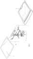
Fig. 2 is an exploded view of the panel and the frame with the operating mechanism of the panel assembled. -
Fig. 3 is an exploded view similar to that ofFig. 2 but showing the operating mechanism in exploded view as well. -
Fig. 4 shows the exploded operating mechanism ofFig. 3 on a larger scale. -
Fig. 5 is a perspective view of the motor and the operating mechanism. -
Fig. 6 is a schematic side view of the motor, the operating mechanism, part of the panel and the frame and part of the fixed roof. -
Fig. 7 is a schematic side view similar to that ofFig. 6 , but showing the gearbox in a sectional view. -
Fig. 8 is a schematic cross section according to line VIII-VIII infig. 5 showing the connection between the motor support of the gearbox and the frame. -
Fig. 9 is a schematic sectional side view according to line IX-IX infig. 5 , showing worm wheel, gearwheel, gearbox, and motor. -
Fig. 10 is a schematic sectional view along line X-X infig. 5 showing the rotation rod. -
Fig. 11 is a schematic side view of the lever assembly showing the bearing in the hinges of one of the lever assemblies. -
Figs. 12a and b are schematic plan views of the outline of the panel, the outline of the headliner and a first and a second embodiment of the positions of the of lever assemblies. - Referring to
fig. 1 a vehicle roof is shown having an open roof construction, in which a roof opening 2 in the vehicle roof can be opened and closed by apanel 1. Thispanel 1 is part of the open roof construction of the vehicle. Thepanel 1 in this case is a rigid, at least partly transparent panel, made of glass, plastics or the like. The open roof construction is of the so-called "pop up" type, which means that the operating mechanism of the open roof construction is capable of moving thepanel 1 at its rear end upwardly to open thepanel 1 and downwardly again to close thepanel 1. Thepanel 1 in this embodiment comprises hinges on its front side, so that thepanel 1 can only rotate and not move in longitudinal direction of the open roof construction and vehicle. Some longitudinal movement at the front of the panel would be conceivable, but in a controlled manner in which the longitudinal movement is dependable on the rotational movement. - The
openable panel 1 may be a top loaded open roof construction or a bottom loaded roof construction, meaning that the open roof construction when assembled in the vehicle may be assembled from the upper (top) side of the roof of the vehicle or the from the lower (bottom) side of the roof. The drawings in this document show a top loaded open roof construction. Infig. 2 , thepanel 1 is shown separately from aframe 4 of the open roof construction. A small part of theframe 4 is shown e.g., inFigs. 6 - 8 . On theframe 4 are attached adrive motor 5, agearbox 12 and twolever assemblies 13, 13' which parts are clearly shown infig. 3 . Thedrive motor 5 is placed in the vicinity of therear edge 6 of theopening 2 in the fixedroof 3 and in the vicinity of alongitudinal centre line 7 of the opening, seeFig. 1 . - As is shown in
figs. 3 and4 , themotor 5 is mounted to the lower side of amotor support 17 by means ofscrews 19 inserted from below. Thismotor support 17 is part of the additional ("add-on")gearbox 12, which is separate from an internal gearbox of themotor 5. - The
motor 5 has agearwheel 30 on an output shaft 8 (fig. 9 ) whichgearwheel 30 is normally used for engaging drive cables of an operating mechanism. In this open roof construction, thegearwheel 30 of theoutput shaft 8 fits into a receiving shaft (i.e., theinput shaft 29 and aworm wheel 26 carried thereby) of the gearbox 12 (seefig. 9 ). Theoutput shaft 8 of themotor 5 is oriented in vertical direction and a drive shaft (i.e., a rotation rod 15) for thelever assemblies 13, 13' is oriented in a horizontal direction transverse to the open roof construction. Theworm wheel 26 on theinput shaft 29 and agearwheel 27 on the rotation rod 15 (together forming a set of gearwheels 16) cause the torque of themotor 5 to be transferred from thevertical output shaft 8 to the horizontally orientedrotation rod 15 for thelever assemblies 13, 13'. Thelever assemblies 13, 13' are attached in a rotationally fixed manner at the extreme ends 18, 18' of therotation rod 15. -
Figs. 10, 11 show that eachlever assembly 13, 13' comprises a first lever and a second lever. At each extreme end of the first and second lever of theassemblies 13, 13', a hinge 21, 21' is arranged whereby between the first and second lever only one hinge 21, 21' is present. Thelever assemblies 13, 13' are connected at one end to the inside of thepanel 1 by means of the respective hinge 21, 21'. For this connection, apanel bracket 31 is glued to the inside of thepanel 1. This panel bracket has connection points for the hinges 21, 21' of thelever assemblies 13, 13', such that forces, transferred via thelever assemblies 13, 13', can be exerted to thepanel 1. As the longitudinal movement of thepanel 1 at the hinges 21, 21' is dependable on the rotation ofpanel 1, the rotation of the first lever of thelever assemblies 13, 13' is controlled by therotation rod 15 and the rotation of the second lever is controlled by the rotation of the first lever and the rotation of thepanel 1. - Referring to
figs. 4 ,5 , and8 - 10 , thegearbox 12 is shown in further detail. Thegearbox 12 comprises a gearbox housing which is partly formed by themotor support 17, which is such thatvibration dampers 14 may be mounted to it. Thevibration dampers 14 may be mounted to themotor support 17 by sliding them into a cavity formed in themotor support 17. Screws 32 (only one is shown infigs. 4 and8 ) are used to attach an inner bush of thevibration dampers 14 to theframe 4. Themotor support 17 is only in contact with (the circumference of) a rubber part of thevibration damper 14 so that themotor support 17 and themotor 5 mounted to it are isolated from theframe 4. - The
motor support 17 forms a bottom wall of thegearbox 12 and rotatably accommodates theworm wheel 26, thegearwheel 27 and therotation rod 15 by means ofbearings 20, 20', 28 (fig. 10 ) that comprise vibration-damping materials. Further, themotor support 17 at its upper side comprises acover 33 to form a gearbox housing. Thecover 33 is fixed by means ofscrews 34 to themotor support 17. - In
fig. 5 , thegearbox 12 is shown in an assembled condition with underneath themotor support 17 themotor 5 attached to it. - In
fig. 6 a side view is shown whereby thepanel 1 is shown in an open position (solid lines) and in closed position (dotted lines). The fixedroof 3 is shown partly and as such only a section of the rear edge of theopening 6 is visible. Theframe 4 is mounted on a flange of the fixedroof 3 by means of glue, however also fixing methods using screws or the like are conceivable. Theframe 4 is made of plastic, however it is also conceivable that theframe 4 is made of steel or another metal. On the upper side of the flange of the frame 4 a seal is mounted, with which thepanel 1 is in contact when thepanel 1 is closed and which seal provides a water and noise tight closure between theframe 4 and theclosed panel 1. Themotor 5 is shown below thegearbox 12. Thelever assemblies 13, 13' are shown in a position when thepanel 1 is in an open position (solid lines), and in a position in which thepanel 1 is in a closed position (dotted lines). - In
fig. 7 , in a similar view as infig. 6 , thegearbox 12 is shown with a section through the set of gearwheels 16 (which includesworm wheel 26 and gearwheel 27), theoutput shaft 8 of themotor 5 and therotation rod 15. In this view is shown how the torque from themotor 5 is transferred from the output shaft 8 (Fig. 9 ) of themotor 5 via theworm wheel 26 to the gearwheel 27 (Fig. 9 ), the latter being connected to therotation rod 15. Thelever assemblies 13, 13', which are arranged on the extreme ends 18, 18' (Fig. 10 ) of therotation rod 15, are rotationally driven to open or close thepanel 1. - In
fig. 8 a sectional side view through themotor 5,thegearbox 12 and theframe 4 is shown. The section is taken through one of the fixings of themotor support 17 of thegearbox 12 to theframe 4, showing thevibration damper 14 and the fixingscrew 32. Thescrew 32 does not touch thegearbox 12 and thevibration dampers 14 damp the vibrations arising from the operation of themotor 5 and thus do not reach theframe 4. - In
fig. 9 a sectional view is shown in a similar section as is shown infig. 7 , but only showing themotor 5 andgearbox 12. Themotor 5 comprises theoutput shaft 8, which is equipped with agearwheel 30. Thisgearwheel 30 fits into thehollow worm wheel 26 supported by theinput shaft 29. The cavity in theworm wheel 26 has gear teeth that fit into opposite gear teeth of thegearwheel 30 of theoutput shaft 8 of themotor 5. -
Fig. 10 shows a section through therotation rod 15 showing thebearings 20, 20' comprising vibration damping material and thelevers 13, 13' at the extreme ends 18, 18' of therotation rod 15. - In
fig. 11 in a side view one of thelever assemblies 13, 13' is shown with the hinge points 21, 21' and the bearings 22, 22' comprising vibration damping material in the hinge points 21, 21'. - In
fig. 12a an embodiment is shown in which therotation rod 15 is limited in transverse length whereby the extreme ends 18, 18' of therotation rod 15 are positioned near the short ends of thegearbox 12 to the left and right of thecentre line 7 of the vehicle. So, in this embodiment thepanel 1 is supported on its rear side in a central area only. - In
fig. 12b another embodiment is shown wherein therotation rod 15 extends to the vicinity of the lateral sides 24, 24' of thepanel 1. In this embodiment thelever assemblies 13, 13' are connected to thepanel 1 at the lateral sides 24, 24' of thepanel 1 and thus in this embodiment the rear corners of thepanel 1 may be pulled down by thelever assemblies 13, 13'. While in the embodiment offig. 12a thepanel 1 may be pulled down in the centre area closer to thelongitudinal centreline 7 of the vehicle. - The invention is not limited to the embodiments described before which may be varied widely within the scope of the invention as defined in the appended claims. For instance, it may be conceivable that the
rotation rod 15 is equipped withadditional lever assemblies 13, 13'. The rotation rod may extend in transverse direction up to the lateral sides 24, 24' of thepanel 1 and comprises at both extreme ends 18, 18' a first andsecond lever assembly 13, 13' attached to thepanel 1. In the area closer to the longitudinal centre line of the vehicle a third and fourth lever assembly is attached to thepanel 1. In such case the four lever assemblies may exert an even force to thepanel 1 when thepanel 1 is in its closed position to be able to have an even seal pressure along the rear edge of thepanel 1. Eachlever assembly 13, 13' may comprise more or less than the pair of levers shown in the drawings. It comprises at least a lever combined with one or more structural elements like levers, slides etc. The motor support may form a part of the additional gearbox or may be a separate part supporting the gearbox. The former embodiment of course has the advantage of a smaller vertical packaging and reduced number of parts.
Claims (13)
- An open roof construction for a vehicle having an opening (2) in its fixed roof (3), comprising:at least a panel (1), capable of at least partly opening and closing the opening (2) in the fixed roof (3) of the vehicle by means of at least one lever assembly connected to the panel (1),a stationary frame (4) fitted in the opening of the fixed roof,a drive motor (5) placed in the vicinity of the rear edge (6) of the opening (2) in the fixed roof (3) and in the vicinity of a longitudinal centre line (7) of the opening, said drive motor (5) comprising an output shaft (8) having a centre axis (9) which is perpendicular to a centre axis (10) of a rotor shaft (11) of the drive motor (5), said drive motor (5) being connected to a motor support (17) which is attached to the frame (4) by means of vibration dampers (14),wherein the motor support (17) supports a separate gearbox (12) comprising a set of gear wheels (16) to transfer the torque from the output shaft (8) of the motor (5) through 90 degrees to a rotation rod (15) of the gearbox (12), extending in a transverse direction of the open roof construction, and then to the at least one lever assembly (13, 13') connected to the panel (1).
- The open roof construction according to claim 1, wherein the at least one lever assembly (13, 13') is attached to each end of the rotation rod (18, 18').
- The open roof construction according to claim 1, wherein the drive motor (5) is connected to the motor support by means of screws (19).
- The open roof construction according to claim 1, wherein the rotation rod (15) is isolated from the motor support (17) by means of at least one bearing (20, 20') equipped with vibration damping material.
- The open roof construction according to claim 1, wherein the lever assembly is equipped at a hinge point (21, 21') with a bearing (22, 22') comprising vibration-damping material.
- The open roof construction according to claim 2, wherein the rotation rod (15) extends in transverse direction of the open roof construction such that the lever assemblies (13, 13') mounted at the extreme ends (18, 18') of the rod are positioned near the short sides of the motor (5) and within the boundaries of the inner side of a headliner (23) when the panel (1) is in a closed position.
- The open roof construction according to claim 2, wherein the rotation rod (15) extends in transverse direction of the open roof construction such that the lever assemblies (13, 13') mounted at the extreme ends (18, 18') of the rod (15) are positioned in the vicinity of lateral sides (24, 24') of the panel (1).
- The open roof construction according to claim 1, wherein a bearing (25) comprising vibration damping material is mounted on an input shaft (29) of the gearbox (12).
- The open roof construction according to claim 1, wherein the set of gearwheels (16) comprises a worm wheel (26) connected to an input shaft (29) of the gearbox (12) and a gear wheel (27) attached to the rotation rod (15).
- The open roof construction according to claim 9, wherein the gear wheel (27) is equipped with a bearing (28) comprising vibration damping material.
- The open roof construction according to claim 1, wherein the motor support (17) forms a bottom wall of the gearbox (12).
- The open roof construction according to claim 11, wherein the motor support (17) at least partly accommodates a set of gearwheels (16) of the gearbox (12).
- A vehicle comprising the open roof construction of any of the preceding claims.
Priority Applications (2)
| Application Number | Priority Date | Filing Date | Title |
|---|---|---|---|
| CN202111548371.XA CN114673776A (en) | 2020-12-24 | 2021-12-17 | Central pop-up gearbox on standard platform motor |
| US17/645,676 US20220205304A1 (en) | 2020-12-24 | 2021-12-22 | Central pop-up gearbox on standard platform motor |
Applications Claiming Priority (1)
| Application Number | Priority Date | Filing Date | Title |
|---|---|---|---|
| EP20217306 | 2020-12-24 |
Publications (2)
| Publication Number | Publication Date |
|---|---|
| EP4019307A1 EP4019307A1 (en) | 2022-06-29 |
| EP4019307B1 true EP4019307B1 (en) | 2024-05-01 |
Family
ID=73943217
Family Applications (1)
| Application Number | Title | Priority Date | Filing Date |
|---|---|---|---|
| EP21207311.8A Active EP4019307B1 (en) | 2020-12-24 | 2021-11-09 | Central pop-up gearbox on standard platform motor |
Country Status (3)
| Country | Link |
|---|---|
| US (1) | US20220205304A1 (en) |
| EP (1) | EP4019307B1 (en) |
| CN (1) | CN114673776A (en) |
Family Cites Families (8)
| Publication number | Priority date | Publication date | Assignee | Title |
|---|---|---|---|---|
| JPS56155925U (en) * | 1980-04-19 | 1981-11-20 | ||
| FI79488C (en) * | 1988-01-19 | 1990-01-10 | Parton Oy Ab | OEPPNINGS- OCH STAENGNINGSANORDNING FOER TAKLUCKA I FORDON. |
| JPH04134161U (en) * | 1991-06-04 | 1992-12-14 | 株式会社三ツ葉電機製作所 | Motor with worm reducer |
| DE4323946C2 (en) * | 1993-07-16 | 1999-02-25 | Webasto Karosseriesysteme | Drive device for an adjustable vehicle part |
| NL1002589C2 (en) * | 1996-03-13 | 1997-09-17 | Inalfa Ind Bv | Drive unit; as well as a vehicle open roof structure constructed with a drive unit. |
| EP2098396B1 (en) * | 2008-03-04 | 2012-05-16 | Inalfa Roof Systems Group B.V. | Drive unit for at least two movable parts of a vehicle, in particular a roof assembly thereof |
| US8905185B2 (en) * | 2009-12-23 | 2014-12-09 | Mando Corporation | Reducer of electric power steering apparatus |
| EP3326851B2 (en) * | 2016-11-28 | 2022-06-22 | Inalfa Roof Systems Group B.V. | Roof closure assembly |
-
2021
- 2021-11-09 EP EP21207311.8A patent/EP4019307B1/en active Active
- 2021-12-17 CN CN202111548371.XA patent/CN114673776A/en active Pending
- 2021-12-22 US US17/645,676 patent/US20220205304A1/en active Pending
Also Published As
| Publication number | Publication date |
|---|---|
| EP4019307A1 (en) | 2022-06-29 |
| US20220205304A1 (en) | 2022-06-30 |
| CN114673776A (en) | 2022-06-28 |
Similar Documents
| Publication | Publication Date | Title |
|---|---|---|
| US7566087B2 (en) | Power closure assembly | |
| AU2014324065B2 (en) | Swinging-sliding door module for a rail vehicle with improved over-centre locking | |
| US7097230B2 (en) | Power actuator system for actuating a closure member | |
| US8469439B2 (en) | Vehicle body rear structure | |
| JP5281084B2 (en) | Vehicle having at least one tailgate | |
| JP3715804B2 (en) | Openable interior device | |
| US6820920B2 (en) | Vehicle rear structure | |
| US6862846B1 (en) | Door module for a motor vehicle with pivotally attached sections | |
| CN1534159A (en) | Motion damping device of mouvable furniture parts in its closed region | |
| WO2016006141A1 (en) | Power-door opening and closing device and automobile provided with opening and closing device | |
| EP4019307B1 (en) | Central pop-up gearbox on standard platform motor | |
| JP2006116997A (en) | Rear gate structure | |
| JP5402333B2 (en) | Switchgear and window using the same | |
| JPS6410380B2 (en) | ||
| WO2019178196A1 (en) | Vehicle closure actuator assembly | |
| ATE358224T1 (en) | GEAR FOR SWINGING A VEHICLE DOOR OR VEHICLE HATCH | |
| CN111002800A (en) | Door glass assembly for vehicle | |
| EP1169188B1 (en) | Door module | |
| US7083221B2 (en) | Arrangement structure of vehicle door open-close device | |
| CN217919615U (en) | Automatic uncovering structure and garbage can | |
| KR100223113B1 (en) | Door hinge with door checker for automobile | |
| US20230118226A1 (en) | Structure of flap part for covering rail part when opening sliding door of vehicle | |
| JP2003336441A (en) | Automatic opening/closing device for vehicle | |
| JPH09104228A (en) | Vehicular door | |
| KR100463163B1 (en) | Glove box damper device of automobile |
Legal Events
| Date | Code | Title | Description |
|---|---|---|---|
| PUAI | Public reference made under article 153(3) epc to a published international application that has entered the european phase |
Free format text: ORIGINAL CODE: 0009012 |
|
| STAA | Information on the status of an ep patent application or granted ep patent |
Free format text: STATUS: THE APPLICATION HAS BEEN PUBLISHED |
|
| AK | Designated contracting states |
Kind code of ref document: A1 Designated state(s): AL AT BE BG CH CY CZ DE DK EE ES FI FR GB GR HR HU IE IS IT LI LT LU LV MC MK MT NL NO PL PT RO RS SE SI SK SM TR |
|
| STAA | Information on the status of an ep patent application or granted ep patent |
Free format text: STATUS: REQUEST FOR EXAMINATION WAS MADE |
|
| 17P | Request for examination filed |
Effective date: 20221223 |
|
| RBV | Designated contracting states (corrected) |
Designated state(s): AL AT BE BG CH CY CZ DE DK EE ES FI FR GB GR HR HU IE IS IT LI LT LU LV MC MK MT NL NO PL PT RO RS SE SI SK SM TR |
|
| RIC1 | Information provided on ipc code assigned before grant |
Ipc: E05F 15/697 20150101ALI20231031BHEP Ipc: B60J 7/057 20060101AFI20231031BHEP |
|
| GRAP | Despatch of communication of intention to grant a patent |
Free format text: ORIGINAL CODE: EPIDOSNIGR1 |
|
| STAA | Information on the status of an ep patent application or granted ep patent |
Free format text: STATUS: GRANT OF PATENT IS INTENDED |
|
| INTG | Intention to grant announced |
Effective date: 20231211 |
|
| GRAS | Grant fee paid |
Free format text: ORIGINAL CODE: EPIDOSNIGR3 |
|
| GRAA | (expected) grant |
Free format text: ORIGINAL CODE: 0009210 |
|
| STAA | Information on the status of an ep patent application or granted ep patent |
Free format text: STATUS: THE PATENT HAS BEEN GRANTED |
|
| AK | Designated contracting states |
Kind code of ref document: B1 Designated state(s): AL AT BE BG CH CY CZ DE DK EE ES FI FR GB GR HR HU IE IS IT LI LT LU LV MC MK MT NL NO PL PT RO RS SE SI SK SM TR |
|
| REG | Reference to a national code |
Ref country code: GB Ref legal event code: FG4D |