EP3326757A2 - Ensemble cylindre pour un dispositif d'entraînement de fixation de ressort à gaz - Google Patents
Ensemble cylindre pour un dispositif d'entraînement de fixation de ressort à gaz Download PDFInfo
- Publication number
- EP3326757A2 EP3326757A2 EP17200925.0A EP17200925A EP3326757A2 EP 3326757 A2 EP3326757 A2 EP 3326757A2 EP 17200925 A EP17200925 A EP 17200925A EP 3326757 A2 EP3326757 A2 EP 3326757A2
- Authority
- EP
- European Patent Office
- Prior art keywords
- cylinder
- inner cylinder
- fastener
- gas
- driver
- Prior art date
- Legal status (The legal status is an assumption and is not a legal conclusion. Google has not performed a legal analysis and makes no representation as to the accuracy of the status listed.)
- Granted
Links
- 238000003860 storage Methods 0.000 claims description 39
- 238000000034 method Methods 0.000 claims description 15
- 238000004891 communication Methods 0.000 claims description 12
- 239000012530 fluid Substances 0.000 claims description 12
- 230000008569 process Effects 0.000 claims description 8
- 238000005096 rolling process Methods 0.000 claims description 6
- 238000001125 extrusion Methods 0.000 claims description 5
- 238000004519 manufacturing process Methods 0.000 claims description 3
- 230000002093 peripheral effect Effects 0.000 claims description 2
- 230000004044 response Effects 0.000 claims description 2
- 230000005540 biological transmission Effects 0.000 description 6
- 230000008878 coupling Effects 0.000 description 4
- 238000010168 coupling process Methods 0.000 description 4
- 238000005859 coupling reaction Methods 0.000 description 4
- 230000008901 benefit Effects 0.000 description 2
- 230000000977 initiatory effect Effects 0.000 description 2
- 239000000463 material Substances 0.000 description 2
- 230000004913 activation Effects 0.000 description 1
- 238000005266 casting Methods 0.000 description 1
- 238000010276 construction Methods 0.000 description 1
- 238000010304 firing Methods 0.000 description 1
- 238000003754 machining Methods 0.000 description 1
- 230000013011 mating Effects 0.000 description 1
- 230000007246 mechanism Effects 0.000 description 1
- 238000000465 moulding Methods 0.000 description 1
- 238000012354 overpressurization Methods 0.000 description 1
- 230000002035 prolonged effect Effects 0.000 description 1
- 230000008439 repair process Effects 0.000 description 1
- 230000000717 retained effect Effects 0.000 description 1
- 238000007789 sealing Methods 0.000 description 1
- 238000003466 welding Methods 0.000 description 1
Images


Classifications
-
- B—PERFORMING OPERATIONS; TRANSPORTING
- B25—HAND TOOLS; PORTABLE POWER-DRIVEN TOOLS; MANIPULATORS
- B25C—HAND-HELD NAILING OR STAPLING TOOLS; MANUALLY OPERATED PORTABLE STAPLING TOOLS
- B25C1/00—Hand-held nailing tools; Nail feeding devices
- B25C1/008—Safety devices
-
- B—PERFORMING OPERATIONS; TRANSPORTING
- B25—HAND TOOLS; PORTABLE POWER-DRIVEN TOOLS; MANIPULATORS
- B25C—HAND-HELD NAILING OR STAPLING TOOLS; MANUALLY OPERATED PORTABLE STAPLING TOOLS
- B25C1/00—Hand-held nailing tools; Nail feeding devices
- B25C1/04—Hand-held nailing tools; Nail feeding devices operated by fluid pressure, e.g. by air pressure
- B25C1/047—Mechanical details
-
- B—PERFORMING OPERATIONS; TRANSPORTING
- B25—HAND TOOLS; PORTABLE POWER-DRIVEN TOOLS; MANIPULATORS
- B25C—HAND-HELD NAILING OR STAPLING TOOLS; MANUALLY OPERATED PORTABLE STAPLING TOOLS
- B25C1/00—Hand-held nailing tools; Nail feeding devices
- B25C1/06—Hand-held nailing tools; Nail feeding devices operated by electric power
Definitions
- the present invention relates to powered fastener drivers, and more particularly to gas spring-powered fastener drivers.
- fastener drivers used to drive fasteners (e.g., nails, tacks, staples, etc.) into a workpiece known in the art.
- fastener drivers operate utilizing various means (e.g., compressed air generated by an air compressor, electrical energy, flywheel mechanisms) known in the art, but often these designs are met with power, size, and cost constraints.
- the present invention provides, in one aspect, a gas spring-powered fastener driver including a cylinder, a moveable piston positioned within the cylinder, and a driver blade attached to the piston and moveable therewith from a retracted position to a driven position to drive a fastener into a workpiece.
- the gas spring-powered fastener driver further includes a fill valve coupled to the cylinder and operable to selectively fill the cylinder with gas to a pressure.
- the fastener driver may further comprise a pressure relief valve coupled to the cylinder and operable to release gas from the cylinder when the pressure exceeds a first predetermined pressure.
- the cylinder may include a portion that is configured to rupture to release gas from the cylinder when the pressure in the cylinder exceeds a second predetermined pressure that is greater than the first predetermined pressure.
- the portion configured to rupture may be a thin-wall portion.
- the cylinder may be an inner cylinder and the fastener driver may further comprise an outer cylinder surrounding the inner cylinder.
- the space between the outer cylinder and the inner cylinder may define a gas storage chamber.
- the thin-wall portion may be defined by a blind bore within an annular wall of the inner cylinder engaged with the outer cylinder.
- the thin-wall portion may separate the gas storage chamber and a blind end of the bore.
- An opposite, open end of the bore may be in fluid communication with atmosphere.
- the thin-wall portion may be contiguous with a tapered wall of the inner cylinder adjacent the annular wall that is engaged with the outer cylinder.
- the second predetermined pressure may be about 150 psi.
- the first predetermined pressure may be about 120 psi.
- the fill valve may be a Schrader valve.
- the fastener driver may further comprise a housing enclosing the cylinder and a removable cover to selectively provide access to the fill valve.
- the cylinder may be an inner cylinder, and the fastener driver may further comprise an outer cylinder surrounding the inner cylinder.
- the space between the outer cylinder and the inner cylinder may define a gas storage chamber.
- An upper open end of the inner cylinder may be in fluid communication with the gas storage chamber.
- the fill valve may discharge pressurized gas into at least one of the gas storage chamber or the inner cylinder.
- the outer cylinder may include a rear wall. The fill valve may be at least partially supported by the rear wall.
- the present invention provides, in another aspect, a gas spring-powered fastener driver including a housing and cylinder assembly.
- the cylinder assembly includes a cylinder containing a compressed gas, a moveable piston positioned within the cylinder, and a driver blade attached to the piston and moveable therewith from a retracted position to a driven position to drive a fastener into a workpiece.
- the cylinder assembly may further include a bumper positioned within the cylinder to retain the moveable piston within the cylinder.
- the cylinder assembly may be removably coupled to the housing.
- the housing may include a removable cover to provide access to the cylinder assembly for removal.
- the cylinder, the moveable piston, the driver blade, and the bumper may be removable from the housing, through an opening upon removal of the cover, as a unit.
- the cylinder may be an inner cylinder and the fastener driver may further comprise an outer cylinder surrounding the inner cylinder.
- the space between the outer cylinder and the inner cylinder may define a gas storage chamber.
- the cylinder assembly may further comprise an end cover positioned adjacent an end of the inner cylinder proximate the bumper.
- the fastener driver may further comprise a mounting plate affixed to the housing.
- the cylinder assembly may be fastened to the housing via the mounting plate.
- the fastener driver may further comprise: aligned bores in the mounting plate, the end cover, and the inner cylinder, respectively; and a fastener received within each of the bores to secure the inner cylinder and the end cover to the mounting plate.
- the bore in the inner cylinder may be in fluid communication with the gas storage chamber.
- the fastener when threaded to the bore in the inner cylinder, may seal the bore in the inner cylinder.
- the compressed gas within the gas storage chamber may be released to depressurize the cylinder in response to removal of the fastener from the respective bores in the mounting plate, the end cover, and the inner cylinder.
- the cylinder assembly may be removable from the housing after the fastener is removed from the respective bores in the mounting plate, the end cover, and the inner cylinder.
- the cylinder assembly may include a second fastener for securing the end cover to the inner cylinder.
- the end cover may remain secured to the inner cylinder upon removal of the cylinder assembly from the housing.
- the end cover may retain the bumper and the piston within the inner cylinder.
- the second fastener may be removable from the inner cylinder.
- the bumper, the piston and the driver blade may be axially removable from the inner cylinder when the end cover is removed from the inner cylinder.
- the outer cylinder may include a radially inward-extending projection received within a circumferentially extending groove in an outer peripheral surface of the inner cylinder to axially retain the outer cylinder to the inner cylinder.
- the outer cylinder may include a radially inwardly turned flange at least partially overlapping a tapered bottom end of the inner cylinder.
- the end cover may include an annular flange groove into which the flange is at least partially received to sandwich the flange between the end cover and the inner cylinder, which may thereby secure the flange over the bottom end of the inner cylinder.
- the present invention provides, in yet another aspect, a method of manufacturing a pressure vessel.
- the method includes forming an outer cylinder including an annular wall, positioning an inner cylinder within the outer cylinder, and deforming the annular wall of the outer cylinder to engage a portion of the inner cylinder to retain the inner cylinder within the outer cylinder and form the pressure vessel.
- Deforming the annular wall of the outer cylinder may include deforming the annular wall radially inward into a groove defined by the inner cylinder.
- the groove defined by the inner cylinder may be annular.
- Deforming the annular wall radially inward may include deforming the annular wall about a circumference of the annular wall into the annular groove. Deforming the annular wall radially inward may include using a rolling process.
- Deforming the annular wall of the outer cylinder may include deforming an end of the annular wall radially inward to form a flange to retain the inner cylinder.
- the method may further comprise forming the outer cylinder using an impact extrusion process.
- the method may further comprise forming the inner cylinder using an impact extrusion process.
- FIGS. 1A-2 illustrate a gas spring-powered fastener driver 10 operable to drive fasteners (e.g., nails, tacks, staples, etc.) into a workpiece.
- the fastener driver 10 includes a nosepiece 14, and a magazine 18 for sequentially feeding fasteners (e.g., collated fasteners) into the nosepiece 14 prior to each fastener-driving operation.
- the fastener driver 10 further includes a gas cylinder assembly 22 removably coupled to a mounting plate 30 of an internal frame structure 26 (i.e., housing), as shown in FIGS. 3-4 .
- the gas cylinder assembly 22 includes an inner piston cylinder 34 and a moveable piston 36 positioned within the inner cylinder 34.
- the fastener driver 10 further includes a driver blade 38 that is attached to the piston 36 via a threaded end 40 ( FIG. 5 ) and moveable therewith.
- the driver blade 38 extends through the internal frame structure 26 such that a tip 42 of the driver blade 38 is received within the nosepiece 14.
- the fastener driver 10 does not require an external source of air pressure, but rather the gas cylinder assembly 22 further includes an outer cylinder 44 containing pressurized gas (e.g., air) in fluid communication with the inner cylinder 34.
- the inner cylinder 34 is positioned concentrically within the outer cylinder 44.
- the inner cylinder 34 and the driver blade 38 define a driving axis A ( FIG. 6 ), and during a driving cycle the driver blade 38 and piston 36 are moveable between a retracted or ready position (see FIG. 6 ) and a driven position (i.e., bottom dead center; see FIG. 7 ).
- the fastener driver 10 further includes a lifting assembly 48, which is driven by a motor 50 ( FIG. 2 ) via a transmission 51 ( FIG. 2 ), and which is operable to move the driver blade 38 from the driven position to the ready position.
- the lifting assembly 48 is generally enclosed in and supported by the internal frame structure 26.
- the driver blade 38 includes a plurality of first teeth 52 positioned along one side of the driver blade 38 and a plurality of second teeth 54 positioned along an opposite side of the driver blade 38.
- the lifting assembly 48 further includes a pinion 55 drivingly coupled to a lifter 56 having three bearings 58 positioned circumferentially about the lifter 56. The bearings 58 are configured to engage the first teeth 52 as the lifter 56 rotates to move the driver blade 38 to the ready position ( FIG. 6 ).
- a spring biased latch 60 is pivotably mounted to the internal frame structure 26 and is biased into engagement with the second teeth 54 as the driver blade 38 is moved to the ready position and while in the ready position to prevent movement of the driver blade 38 towards the driven position.
- the latch 60 is arranged to be operatively disengaged from the second teeth 54 by actuation of a solenoid 62 ( FIG. 1B ) to release the driver blade 38 and the piston 36, such that the piston 36 and the driver blade 38 are thrust downwards toward the driven position ( FIG. 7 ) by the expanding gas within the gas cylinder assembly 22.
- the fastener driver 10 may include an outer housing 66 having a cylinder support portion 68 in which the gas cylinder assembly 22 may be at least partially positioned, a handle portion 70 graspable by a user during normal operation, and a transmission housing portion 72 in which the transmission 51 is at least partially positioned.
- a trigger 74 which is depressible by the user of the fastener driver 10 to initiate a fastener driving operation, is adjacent the handle portion 70.
- at least two selected from the group of the cylinder support portion 68, the handle portion 70, and the transmission housing portion 72 may be formed together as a generally singular piece (i.e., two halves formed using a casting or molding process, depending on the material used).
- the housing 66 is formed from plastic.
- the motor 50 is coupled to the internal frame structure 26 and selectively provides torque to the transmission 51 to rotationally drive the lifter 56 of the lifting assembly 48 when activated.
- a battery 78 ( FIG. 1A ) is electrically connected to the motor 50 for supplying electrical power to the motor 50.
- the trigger 74 may be actuated to selectively provide power to the motor 50.
- the battery 78 is mechanically connectable to a battery receptacle 76 formed by the outer housing 66 at a distal end of the handle portion 70 of the housing 66.
- the battery is a rechargeable battery.
- the fastener driver 10 may be powered from an AC voltage input (i.e., from a wall outlet or mains), or by an alternative DC voltage input (e.g., a DC power supply).
- the inner cylinder 34 has a first annular wall 82 defining a cavity 84, and a second annular wall 86 extending axially from the first annular wall 82 to an upper open end 87.
- a tapered wall 83 ( FIG. 6 ) connects the first and second annular walls 82, 84.
- the second annular wall 86 defines a piston bore 88, which receives the piston 36.
- a plurality of bosses 92 ( FIG. 5 ) extend radially into the cavity 84 from the first annular wall 82. The bosses 92 are evenly circumferentially spaced about the axis A, such that a channel 90 is defined between any two adjacent bosses 92.
- bosses 92 define mounting fastener bores 94 ( FIG. 8 ), two of the bosses 92 define end cover fastener bores 96, one of the bosses 92 defines a valve bore 98 ( FIG. 10 ), and one of the bosses 92 defines a safety rupture bore 100 ( FIG. 11 ).
- An outer surface of the first annular wall 82 defines a pair of circumferentially extending seal grooves 102 ( FIG. 8 ) that each receives a first gasket or annular seal 104.
- the outer surface of the first annular wall 82 also defines a circumferentially extending coupling groove 106 positioned axially between a lower end 85 of the inner cylinder 34 and the seal grooves 102. As explained in greater detail below, the groove 106 receives a projection 174 of the outer cylinder 44 to couple the inner cylinder 34 and the outer cylinder 44 together.
- the outer cylinder 44 includes a third annular wall 110 defining a cavity with an inner diameter slightly larger than an outer diameter of the first annular wall 82 of the inner cylinder 34.
- the outer cylinder 44 has an upper end with a rear wall 114 to close off the cavity and an opposite open lower end 112.
- the rear wall 114 is generally semi-spherical with a central recessed portion 116.
- the outer cylinder 44 receives the inner cylinder 34 such that both the first and second annular walls 82, 86 of the inner cylinder 34 extend into the outer cylinder 44.
- the lower end 85 of the inner cylinder 34 is adjacent the lower end 112 of the outer cylinder 44.
- the first gaskets 104 between the seal grooves 102 of the inner cylinder 34 and the inner surface of the outer cylinder 44 provide a gas-tight seal.
- a gas storage chamber 118 is defined between the inner cylinder 34 and the outer cylinder 44.
- the piston bore 88 is in fluid communication with the gas storage chamber 118 via the upper end 87 of the inner cylinder 34.
- the piston 36 defines a pair of circumferentially extending grooves 122 that each receives a second gasket or piston ring 124 for sealing the piston 36 within the piston bore 88.
- the gas cylinder assembly 22 includes a high-pressure side 128 and a low-pressure side 130 that each inversely vary in volume as the piston 36 translates within the piston bore 88.
- the high-pressure side 128 includes a portion of the piston bore 88 above (i.e., toward the rear wall 114 of the outer cylinder 44) the piston 36 and the gas storage chamber 118.
- the low-pressure side 130 beneath (i.e., toward the lower end 112 of the outer cylinder 44) the piston 36.
- the low-pressure side 130 is in fluid communication with atmosphere, as described in more detail below.
- the gas cylinder assembly 22 further includes a cylinder spacing member 134, a bumper 136, and a cylinder end cover 138 ( FIG. 3 ).
- the cylinder spacing member 134 includes an annular cap 142 that receives the upper end 87 of the second annular wall 86 of the inner cylinder 34.
- the annular cap 142 has a rim 144 defining an opening 146.
- the rim 144 supports the spacing member 134 on the upper end 87 of the second annular wall 86.
- the cylinder spacing member 134 further includes a plurality of fins 148 extending radially outward from the annular cap 142. In the illustrated embodiment, there are four fins 148.
- the fins 148 contact both the rear wall 114 and the third annular wall 110 of the outer cylinder 44 to hold the inner cylinder 34 axially in place and to radially center the inner cylinder 34 within the outer cylinder 44.
- the opening 146 in the spacing member 134 allows for fluid communication between the piston bore 88 and the gas storage chamber 118.
- the bumper 136 is positioned within the cavity 84 of the inner cylinder 34.
- the bumper 136 defines a central passage 152 to receive and guide the driver blade 38.
- the bumper 136 also includes radially extending projections 154 evenly circumferentially spaced about the axis A such that a channel 90b is defined between any two adjacent projections 154.
- Each of the projections 154 on the bumper 136 is supported on a corresponding one of the bosses 92 of the inner cylinder 34. Accordingly, the channels 90, 90b of the inner cylinder 34 and the bumper 136 form a plurality of passages extending from the low-pressure side 130 of the piston bore 88 around the bumper 136.
- the bumper 136 may be made of a material to inhibit wear caused by repeated impacts from the piston 36 and friction between the driver blade 38 and the central passage 152.
- the bumper 136 may be made from a wear resistant plastic.
- the cylinder end cover 138 defines a central aperture 160 through which the driver blade 38 extends.
- the end cover 138 further defines a plurality of arcuate slots 162 extending through the end cover 138 and in fluid communication with the low-pressure side 130 side via the passages formed between the bumper 136 and the inner cylinder 34.
- the end cover 138 further defines four mounting fastener apertures 164 and two end cover fastener apertures 166 corresponding to the mounting fastener bores 94 and the end cover fastener bores 96 of the inner cylinder 34, respectively.
- Each of corresponding end cover fastener apertures 166 and end cover fastener bores 96 receive an end cover fastener 168 to couple the end cover 138 to the inner cylinder 34.
- the end cover 138 retains the bumper 136 and the piston 36 within the inner cylinder 34, and the driver blade 38 from being disconnected from the piston 36.
- the inner cylinder 34 is coupled to the outer cylinder 44 by a deformed portion of the third annular wall 110 of the outer cylinder 44 to engage a portion of the inner cylinder 34.
- the third annular wall 110 of the outer cylinder 44 includes a circumferential projection 174 extending radially inward about the third annular wall 110 that engages with the coupling groove 106 to couple the inner and outer cylinders 34, 44 together.
- the end of the third annular wall 110 of the outer cylinder 44 includes a radially inwardly turned flange 176 that overlaps a tapered bottom end of the inner cylinder 34 to retain the inner cylinder 34 within the outer cylinder 44.
- the flange 176 is generally bent an angle of approximately 45 degrees, but may be bent at any other angle (e.g., approximately 60 degrees, approximately 90 degrees, etc.). Engagement between the spacing member 134 and the rear wall 114, and the first annular wall 82 and the flange 176 secures the inner cylinder 34 in place.
- the circumferential projection 174 and the flange 176 are each formed by a deformation process, in which the third annular wall 110 is deformed into engagement with one or more portions of the inner cylinder 34. More specifically, the circumferential projection 174 and the flange 176 may be formed by a rolling process.
- An annular flange groove 170 defined in the cylinder end cover 138 receives the flange 176 to sandwich the flange 176 between the end cover 138 and the inner cylinder 34 and secure the flange 176 over the lower end 85 of the inner cylinder 34.
- the mounting plate 30 of the internal frame structure 26 is similar to the end cover 138 of the gas cylinder assembly 22.
- the mounting plate 30 and the internal frame structure 26 define a central channel 160b for passage of the driver blade 38.
- the mounting plate 30 further defines a plurality of arcuate slots 162b corresponding to the arcuate slots 162 of the end cover 138 so as to fluidly communicate the low-pressure side 130 of the gas cylinder assembly 22 with atmosphere.
- the internal frame structure 26 may be at least partially enclosed within the housing 66.
- the nosepiece 14 may fluidly communicate with atmosphere. Additionally or alternatively, the housing 66 may further define vents to provide fluid communication with atmosphere.
- the mounting plate 30 further defines four mounting fastener apertures 164b corresponding with the mounting fastener apertures 164 in the end cover 138.
- the mounting fastener apertures 164, 164b are aligned with the mounting fastener bores 94 of the inner cylinder 34 so as to receive corresponding mounting fasteners 182 ( FIG. 3 ) to couple the gas cylinder assembly 22 with the internal frame structure 26, and thereby, the fastener driver 10.
- the gas cylinder assembly 22, including the inner cylinder 34, the outer cylinder 44, the bumper 136, the piston 36, the driver blade 38, and the end cover 138, is removable as a unit that can be, for example, serviced or replaced by a user.
- the gas cylinder assembly 22 includes the end cover 138, in other embodiments, the gas cylinder assembly 22 may instead be directly coupled to the mounting plate 30, such that the mounting plate 30 retains the bumper 136 within the cavity 84.
- the gas cylinder assembly 22 is removably coupled to the housing via the mounting fasteners 182, a user may easily service of the gas cylinder assembly 22 in the field.
- the gas cylinder assembly 22 may be replaced with a replacement gas cylinder assembly if a component of the gas cylinder assembly 22 has failed or been damaged.
- one may also replace individual components (e.g., the bumper 136, the driver blade 38, and the piston 36) by removing the end cover 138 to provide access to the cavity 84 and the piston bore 88.
- the mounting fastener bores 94 extend axially through the corresponding bosses 92.
- Each of the mounting fasteners 182 includes two fastener gaskets 184 to inhibit leakage of gas from the gas storage chamber 118 through the mounting fastener bores 94.
- Each of the mounting fastener bores 94 fluidly communicates the gas storage chamber 118 (i.e., the high-pressure side 128) with the cavity 84 (i.e., the low-pressure side 130), when one of the mounting fasteners 182 is removed from the corresponding mounting fastener bore 94.
- the pressure within the gas cylinder assembly 22 is released through the mating threads of the mounting fastener bore 94 and the mounting fastener 182. This allows the pressure to be slowly leaked out as the mounting fasteners 182 are unthreaded from the mounting fastener bores 94 to safely depressurize the gas cylinder assembly 22 before disassembling the gas cylinder assembly 22.
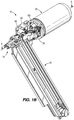
- the gas cylinder assembly 22 further includes a fill valve 188 coupled to the rear wall 114 of the outer cylinder 44 within the recessed portion 116 of the rear wall 114 and along the central axis of the outer cylinder 44.
- the fill valve 188 is configured to be selectively connected with a source of compressed gas via a gas chuck 190 (shown in FIGS. 13-14 ), fluidly connected with a source of compressed gas, such as an air compressor (e.g., a standard air compressor).
- a source of compressed gas such as an air compressor (e.g., a standard air compressor).
- the fill valve 188 permits the gas storage chamber 118 of the gas cylinder assembly 22 to be refilled or recharged with compressed gas if any prior leakage has occurred.
- the gas storage chamber 118 may be filled such that the high-pressure side 128 is at a desired pressure between approximately 90 psi and approximately 150 psi (e.g., approximately 120 psi). In some embodiments, the pressure may be less than 100 psi and greater than 150 psi.
- the fill valve 188 may be configured as a Schrader valve. In other embodiments, the fill valve 188 is configured as a Presta valve, Dunlop valve, or other similar pneumatic fill valve. The fill valve 188 also allows a user to measure and check the pressure within the high-pressure side 128 with any standard pressure gauge device.
- a portable single-use pressurizer 194 may be used to pressurize the high-pressure side 128.
- the portable single-use pressurizer 194 includes a gas chuck 196 (similar to gas chuck 190 of FIGS. 13-14 ), a small tank 198, and a release lever 200.
- the small tank 198 contains enough compressed gas to fill the gas storage chamber 118 with compressed gas to the pressure (e.g., 120 psi) once.
- the gas chuck 190 couples to the fill valve 188 such that the release lever 200 may be actuated by a user to fill the high-pressure side 128 of the gas cylinder assembly 22 to the desired pressure.
- the portable single-use pressurizer 194 does not require external power.
- a rear cover portion 204 of the housing 66 may be removably coupled from the remainder of the housing 66 to provide access to the fill valve 188.
- the cover portion 204 is coupled to the housing 66 via threaded fasteners.
- the cover portion 204 is coupled to the housing 66 via a snap-fit connection.
- the cover portion 204 defines threads that engage with threads defined in a rear opening of the housing 66 (i.e., the cover portion 204 is a threaded cover).
- the valve bore 98 extends through the corresponding boss 92 of the inner cylinder 34 from the gas storage chamber 118 (i.e., the high-pressure side 128) to the cavity 84 (i.e., the low-pressure side 130).
- the valve bore 98 receives and supports a pressure relief valve 208 that is threaded into the valve bore 98.
- the pressure relief valve 208 i.e., a one-way pressure valve
- the first safety pressure is greater than or equal to the desired pressure of the high-pressure side 128 and may be for example between approximately 90 psi and approximately 160 psi (e.g., approximately 125 psi). In some embodiments, the first safety pressure may be less than 90 psi or greater than 160 psi.
- the pressure relief valve 208 prevents the gas storage chamber 118 from being over pressurized. Over pressurization can result in catastrophic failure of the gas cylinder assembly 22.
- the safety rupture bore 100 extends axially into the corresponding boss 92 from the cavity 84 towards the gas storage chamber 118.
- the safety rupture bore 100 defines a rupturable portion 212 of the inner cylinder 34 that is constructed to rupture when the pressure within the gas storage chamber 118 (i.e., the high-pressure side 128) exceeds a second safety pressure (i.e., a second predetermined threshold) that is greater than the first safety pressure.
- a second safety pressure i.e., a second predetermined threshold
- the second safety pressure may be between approximately 120 psi and approximately 180 psi (e.g., approximately 150 psi).
- the second safety pressure may be less than 120 psi or greater than 180 psi.
- the rupturable portion 212 is a thin wall portion of the tapered wall 83 defined adjacent a blind end of the safety rupture bore 100 so as to have a thickness that will rupture once the second safety pressure is reached.
- the rupturable portion 212 provides a pressure relief failsafe for the gas storage chamber 118 in case the pressure relief valve 208 fails or if the pressure in the gas storage chamber 118 increases faster than the pressure relief valve 208 is able to reduce it.
- the gas cylinder assembly 22 is manufactured by first separately forming the inner cylinder 34 and the outer cylinder 44.
- each of the inner cylinder 34 and the outer cylinder 44 may be formed by impact extrusion.
- the seal grooves 102 and the coupling groove 106 is formed in the first annular wall 82 of the inner cylinder 34 (e.g., by a machining process).
- the inner cylinder 34 is inserted inside the outer cylinder 44 with the spacing member 134.
- the open end of the inner cylinder 34 is positioned within the annular cap 142 of the spacing member 134 such that the spacing member 134 centers the inner cylinder 34 within the outer cylinder 44.
- the first gaskets 104 are positioned within the seal grooves 102 of the inner cylinder 34 between the inner cylinder 34 and the outer cylinder 44 to form a gas-tight seal between the first annular wall 82 of the inner cylinder 34 and the third annular wall 110 of the outer cylinder 44.
- the pressure relief valve 208 is inserted into the valve bore 98 of the inner cylinder 34.
- the inner cylinder 34 is coupled with the outer cylinder 44 to form a pressure vessel by deforming a portion of the third annular wall 110 to engage with a portion of the inner cylinder 34.
- a rolling process deforms the third annular wall 110 radially inward, forming the circumferential projection 174 that extends into and engages the coupling groove 106.
- Another rolling process deforms the third annular wall 110 at the lower end 112 of the outer cylinder 44 radially inward to form the flange 176 that retains the inner cylinder 34 within the outer cylinder.
- the rolling processes may be performed independently or simultaneously on the third annular wall 110.
- This gas cylinder assembly 22 process has advantages over welding or fasteners, for example, by reducing weight of the gas cylinder assembly 22, and providing cost savings, among other benefits.
- the driver blade 38 is coupled to the piston 36 via the threaded end 40 of the driver blade 38.
- the piston 36 is then inserted into the piston bore 88 of the inner cylinder 34, such that the driver blade 38 extends out of the inner cylinder 34.
- the second gaskets 124 are positioned between the piston 36 and the inner cylinder 34 to form a gas-tight seal between the piston 36 and the inner cylinder 34.
- the bumper 136 is fitted over the driver blade 38 and positioned within the cavity 84 defined by the first annular wall 82 of the inner cylinder 34.
- the end cover 138 is then positioned such that the driver blade 38 extends through the central aperture 160 and the mounting fastener apertures 164 and the cover fastener apertures 96 align with the mounting fastener bores 94 and the cover fastener bores 96, respectively.
- the end cover fasteners 168 are inserted through the cover fastener apertures 166 and threaded into the cover fastener bores 96.
- the bumper 136, the driver blade 38, and the piston 36 are retained within the inner cylinder 34.
- the gas cylinder assembly 22 as a unit can then be coupled to the internal frame structure 26 of the fastener driver 10.
- the gas cylinder assembly 22 is positioned such that the mounting fastener apertures 164, 164b of the cylinder end cover 138 and the mounting plate 30 are axially aligned.
- the mounting fasteners 182 can then be inserted through the mounting fastener apertures 164, 164b and threaded into the mounting fastener bores 94.
- the fastener gaskets 184 form a gas-tight seal between the mounting fasteners 182 and the inner cylinder 34 within the mounting fastener bores 94.
- the high-pressure side 128 of the gas cylinder assembly 22 may be filled with a gas from a source of compressed gas via the fill valve 188.
- the gas chuck 190 which is fluidly connected with a source of compressed gas (e.g., a gas compressor), is coupled to the fill valve 188 and pressurized to a desired pressure, after which the gas chuck 190 is decoupled from the fill valve 188.
- the pressure relief valve 208 releases pressure within the high-pressure side 128 of the gas cylinder assembly 22 if the pressure exceeds the first safety pressure.
- the thin wall portion 212 also provides a failsafe by rupturing if the pressure exceeds the second safety pressure, which may occur if the pressure relief valve 208 fails or the pressure increases too quickly.
- the lifting assembly 48 drives the piston 36 and the driver blade 38 to the ready position ( FIG. 6 ) by energizing the motor 50.
- the lifter 56 is rotated counterclockwise (as viewed from FIG. 6 ) by the motor 50 via the transmission 51, causing the bearings 58 to engage the first teeth 52 moving the driver blade 38 and the piston 36 toward the ready position along the axis A.
- the spring biased latch 60 engages the second teeth 54 and prevents the piston 36 and driver blade 38 from being forced into the driven position.
- the gas in the piston bore 88 above the piston 36 and the gas within the gas storage chamber 118 i.e., the high-pressure side 128) is further compressed.
- the piston 36 and the driver blade 38 are held in position until being released by user activation of the trigger.
- the compressed gas above the piston 36 and within the gas storage chamber 118 expands and drives the piston 36 and the driver blade 38 to the driven position ( FIG. 7 ), thereby driving a fastener into a workpiece.
- air is forced out of the low-pressure 130, through the cavity 84 and the arcuate slots 162, 162b by the piston 36.
- the illustrated fastener driver 10 therefore operates on a gas spring principle utilizing the lifting assembly 48 and the piston 36 to further compress the gas within the inner cylinder 34 and the outer cylinder 44 (i.e., the high-pressure side 128 of the gas cylinder assembly 22). This process may be repeated to quickly drive multiple fasteners from the magazine into the workpiece using the same compressed gas within the high-pressure side 128 of the gas cylinder assembly 22 repeatedly.
- gas contained within the high-pressure side 128 of the gas cylinder assembly 22 may leak out.
- the gas storage chamber 118 may need to be periodically refilled or recharged by a source of compressed gas.
- a user removes the rear cover portion 204 of the housing 66 ( FIG. 1A ) to access the fill valve 188.
- the user may then remove the valve cap 192, couple the gas chuck 190 connected to the source of compressed gas to the fill valve 188, and fill the gas storage chamber 118 with gas to re-pressurize the high-pressure side 128 to the desired pressure.
- the user may alternatively use a portable single-use pressurizer 194 ( FIG. 14 ) to quickly re-pressurize the high-pressure side 128. This provides an alternative way to pressurizer the gas cylinder assembly 22, when in the field and a gas compressor or other powered device is not readily available.
- a user may disconnect the gas cylinder assembly 22 from the fastener driver 10 as a unit for replacement of the entire gas cylinder assembly 22 or to replace a single component thereof
- the user removes at least a portion of the housing 66 ( FIG. 1A ) to access the gas cylinder assembly 22 and the mounting fasteners 182.
- the user may then remove the mounting fasteners 182 so that the gas cylinder assembly 22 may be disconnected from the mounting plate 30 of the internal frame structure 26 and removed from the fastener driver 10 as a unit.
- the gas within the gas storage chamber 118 leaks out of the mounting fastener bore 94 to depressurize the high-pressure side 128.
- a replacement gas cylinder assembly may then be coupled to the mounting plate 30, as described above in detail.
- the user may disconnect the end cover 138 from the inner cylinder 34 by removing the end cover fasteners 168 from the cover fastener bores 96 of the inner cylinder 34.
- the bumper 136, the piston 36, and the driver blade 38 may be axially removed from the inner cylinder 34.
- the driver blade 38 may be detached from the piston 36 for further disassembly.
- One or more of the bumper 136, the piston 36, and the driver blade 38 may then be swapped out with a corresponding replacement component.
- the user may replace the second gaskets 124 on the piston 36 if they have failed or become worn resulting in leakage and pressure loss.
- the bumper 136, the piston 36, and the driver blade 38 are reassembled and repositioned within the piston bore 88 of the inner cylinder 34.
- the end cover 138 is then reconnected to the inner cylinder 34 to retain the gas cylinder assembly 22 as a single unit, before connecting the gas cylinder assembly 22 to the mounting plate 30, refilling the high-pressure side 128, and reattaching the rear cover portion 204, as described above.
Priority Applications (1)
| Application Number | Priority Date | Filing Date | Title |
|---|---|---|---|
| EP21204276.6A EP3967456A1 (fr) | 2016-11-09 | 2017-11-09 | Ensemble cylindre pour un dispositif d'entraînement de fixation de ressort à gaz |
Applications Claiming Priority (1)
| Application Number | Priority Date | Filing Date | Title |
|---|---|---|---|
| US201662419801P | 2016-11-09 | 2016-11-09 |
Related Child Applications (2)
| Application Number | Title | Priority Date | Filing Date |
|---|---|---|---|
| EP21204276.6A Division-Into EP3967456A1 (fr) | 2016-11-09 | 2017-11-09 | Ensemble cylindre pour un dispositif d'entraînement de fixation de ressort à gaz |
| EP21204276.6A Division EP3967456A1 (fr) | 2016-11-09 | 2017-11-09 | Ensemble cylindre pour un dispositif d'entraînement de fixation de ressort à gaz |
Publications (3)
| Publication Number | Publication Date |
|---|---|
| EP3326757A2 true EP3326757A2 (fr) | 2018-05-30 |
| EP3326757A3 EP3326757A3 (fr) | 2018-11-07 |
| EP3326757B1 EP3326757B1 (fr) | 2022-03-16 |
Family
ID=60301851
Family Applications (2)
| Application Number | Title | Priority Date | Filing Date |
|---|---|---|---|
| EP21204276.6A Pending EP3967456A1 (fr) | 2016-11-09 | 2017-11-09 | Ensemble cylindre pour un dispositif d'entraînement de fixation de ressort à gaz |
| EP17200925.0A Active EP3326757B1 (fr) | 2016-11-09 | 2017-11-09 | Ensemble cylindre pour un dispositif d'entraînement de fixation de ressort à gaz |
Family Applications Before (1)
| Application Number | Title | Priority Date | Filing Date |
|---|---|---|---|
| EP21204276.6A Pending EP3967456A1 (fr) | 2016-11-09 | 2017-11-09 | Ensemble cylindre pour un dispositif d'entraînement de fixation de ressort à gaz |
Country Status (4)
| Country | Link |
|---|---|
| US (3) | US10632600B2 (fr) |
| EP (2) | EP3967456A1 (fr) |
| CN (1) | CN108058137B (fr) |
| CA (2) | CA3187695A1 (fr) |
Cited By (3)
| Publication number | Priority date | Publication date | Assignee | Title |
|---|---|---|---|---|
| CN110091171A (zh) * | 2019-05-24 | 2019-08-06 | 宁波力品格自动化科技有限公司 | 一种气弹簧活塞杆组件的油封总成安装装置 |
| EP3670088A1 (fr) * | 2018-12-20 | 2020-06-24 | Hilti Aktiengesellschaft | Appareil de pose |
| WO2022094190A3 (fr) * | 2020-10-30 | 2022-06-09 | Milwaukee Electric Tool Corporation | Dispositif d'entraînement d'élément de fixation motorisé |
Families Citing this family (27)
| Publication number | Priority date | Publication date | Assignee | Title |
|---|---|---|---|---|
| WO2016127101A1 (fr) | 2015-02-06 | 2016-08-11 | Milwaukee Electric Tool Corporation | Dispositif d'entraînement de fixation alimenté par ressort à gaz |
| CN105818099B (zh) * | 2016-05-26 | 2017-11-17 | 杭州科龙电器工具股份有限公司 | 使用气弹簧的电动钉枪 |
| CA2985110C (fr) * | 2016-11-09 | 2023-05-09 | Tti (Macao Commercial Offshore) Limited | Mecanisme de soulevement et de liberation de bourrage destine a un mecanisme d'entrainement de source de gaz |
| CA3187695A1 (fr) | 2016-11-09 | 2018-05-09 | Tti (Macao Commercial Offshore) Limited | Ensemble de cylindre destine a un mecanisme de fixation de ressort a gaz |
| US10800022B2 (en) * | 2017-02-09 | 2020-10-13 | Illinois Tool Works Inc. | Powered-fastener-driving tool including a driver blade having a varying cross-section |
| US10654160B2 (en) * | 2017-06-20 | 2020-05-19 | Miner Elastomer Products Corporation | Nail gun recoil bumper |
| US20190224825A1 (en) * | 2018-01-24 | 2019-07-25 | Tricord Solutions, Inc. | Gas spring and impacting and driving apparatus with gas spring |
| US11292114B2 (en) * | 2018-01-24 | 2022-04-05 | Tricord Solutions, Inc. | Fastener driving apparatus |
| NZ768772A (en) * | 2018-04-20 | 2022-09-30 | Kyocera Senco Ind Tools Inc | Improved lift mechanism for framing nailer |
| JP7115025B2 (ja) * | 2018-05-18 | 2022-08-09 | 工機ホールディングス株式会社 | 打込機 |
| DE102018117519A1 (de) | 2018-07-19 | 2020-01-23 | Prebena Wilfried Bornemann Gmbh & Co. Kg | Druckluftbetriebene Austreibvorrichtung |
| CN110757413B (zh) | 2018-07-26 | 2022-08-26 | 创科无线普通合伙 | 气动工具 |
| USD900575S1 (en) | 2018-09-26 | 2020-11-03 | Milwaukee Electric Tool Corporation | Powered fastener driver |
| CN110253695B (zh) * | 2018-12-29 | 2021-05-25 | 厦门华蔚物联网科技有限公司 | 一种自动加钉打钉机 |
| US11130221B2 (en) * | 2019-01-31 | 2021-09-28 | Milwaukee Electric Tool Corporation | Powered fastener driver |
| CN110253504B (zh) * | 2019-06-11 | 2022-03-08 | 南京腾亚精工科技股份有限公司 | 一种手持式击打工具 |
| US11951601B2 (en) | 2019-06-14 | 2024-04-09 | Milwaukee Electric Tool Corporation | Lifter mechanism for a powered fastener driver |
| CN217394880U (zh) | 2019-06-14 | 2022-09-09 | 米沃奇电动工具公司 | 动力紧固件驱动器 |
| US20220219301A1 (en) | 2019-06-14 | 2022-07-14 | Milwaukee Electric Tool Corporation | Lifter mechanism for a powered fastener driver |
| WO2021158940A1 (fr) * | 2020-02-05 | 2021-08-12 | Kyocera Senco Industrial Tools, Inc. | Outil d'entraînement d'élément de fixation à ressort à gaz ayant une soupape de remplissage situé dans un capuchon d'extrémité |
| JP7452624B2 (ja) | 2020-03-05 | 2024-03-19 | 工機ホールディングス株式会社 | 打込機 |
| EP4126461A1 (fr) | 2020-03-25 | 2023-02-08 | Milwaukee Electric Tool Corporation | Dispositif d'entraînement d'élément de fixation alimenté en énergie |
| JP7332522B2 (ja) * | 2020-03-31 | 2023-08-23 | 株式会社マキタ | 打ち込み工具 |
| WO2022020987A1 (fr) * | 2020-07-27 | 2022-02-03 | 杭州联和工具制造有限公司 | Cloueuse à alimentation hybride |
| EP4334086A1 (fr) * | 2021-05-07 | 2024-03-13 | Kyocera Senco Industrial Tools, Inc. | Outil d'entraînement d'élément de fixation à ressort à gaz doté d'un capuchon d'extrémité amovible pour réaliser une maintenance ou un entretien |
| WO2023288083A1 (fr) * | 2021-07-16 | 2023-01-19 | Milwaukee Electric Tool Corporation | Dispositif d'entraînement d'élément de fixation motorisé par ressort à gaz avec mécanisme de pression |
| WO2023158729A1 (fr) * | 2022-02-18 | 2023-08-24 | Milwaukee Electric Tool Corporation | Visseuse de fermeture motorisée |
Family Cites Families (50)
| Publication number | Priority date | Publication date | Assignee | Title |
|---|---|---|---|---|
| GB2101277A (en) | 1981-05-28 | 1983-01-12 | Pritchard | Inflating and pressure relieving valve |
| US6123241A (en) * | 1995-05-23 | 2000-09-26 | Applied Tool Development Corporation | Internal combustion powered tool |
| US5749509A (en) * | 1995-06-05 | 1998-05-12 | Sencorp | Resiliently expandable ring seal for combustion chamber of propellant tool |
| JP3676879B2 (ja) * | 1995-07-25 | 2005-07-27 | 株式会社マキタ | 締結具打込み工具 |
| DE19746018C2 (de) | 1997-10-17 | 2000-12-21 | Lechner Gmbh | Verfahren zur Herstellung einer Zweikammerdruckpackung und Vorrichtung zur Durchführung des Verfahrens |
| DE19808295A1 (de) | 1998-02-27 | 1999-11-11 | Boehringer Ingelheim Int | Behälter für eine medizinische Flüssigkeit |
| US6422447B1 (en) | 1998-09-18 | 2002-07-23 | Stanley Fastening Systems, L.P. | Feed system for nailer |
| US6499643B1 (en) | 1998-09-18 | 2002-12-31 | Stanley Fastenening Systems, L.P. | Drive channel for nailer |
| US6431430B1 (en) | 1998-09-18 | 2002-08-13 | Stanley Fastening Systems, L.P. | Battery operated roofing nailer and nails therefor |
| EP1113906A1 (fr) | 1998-09-18 | 2001-07-11 | Stanley Fastening Systems L.P. | Dispositif de pose a chocs |
| TW409787U (en) * | 1999-05-05 | 2000-10-21 | Shiu Kuen Shan | Improved air pressure pump |
| TW435316U (en) * | 1999-06-23 | 2001-05-16 | De Poan Pneumatic Corp | Improved moving valve structure for nailing gun |
| US6672498B2 (en) | 1999-09-17 | 2004-01-06 | Stanley Fastening Sytems Lp | Feed system for nailer |
| US6796478B2 (en) * | 2000-10-12 | 2004-09-28 | Illinois Tool Works Inc. | Fuel cell adapter system for combustion tools |
| US6604664B2 (en) | 2001-01-16 | 2003-08-12 | Illinois Tool Works Inc. | Safe trigger with time delay for pneumatic fastener driving tools |
| US7494035B2 (en) | 2001-04-30 | 2009-02-24 | Black & Decker Inc. | Pneumatic compressor |
| US7225959B2 (en) * | 2001-04-30 | 2007-06-05 | Black & Decker, Inc. | Portable, battery-powered air compressor for a pneumatic tool system |
| US6659127B2 (en) | 2001-06-13 | 2003-12-09 | Larry G. Keast | Relief valve |
| DE20110754U1 (de) * | 2001-06-28 | 2001-10-18 | Prebena Wilfried Bornemann | Netzunabhängiges Eintreibgerät für Befestigungsmittel |
| EP1459850B1 (fr) * | 2003-03-19 | 2008-05-21 | Hitachi Koki Co., Ltd. | Outil entraîné par gaz de combustion avec dispositif pour éviter la surchauffe des composants mécaniques dans l'outil |
| US6938810B2 (en) * | 2003-04-15 | 2005-09-06 | Illinois Tool Works Inc. | Fuel cell adapter system for combustion tools |
| US6722550B1 (en) * | 2003-05-09 | 2004-04-20 | Illinois Tool Works Inc. | Fuel level indicator for combustion tools |
| US6966478B2 (en) | 2003-11-03 | 2005-11-22 | Illinois Tool Works Inc | Combustion apparatus having collapsible volume |
| CN201198823Y (zh) | 2005-05-02 | 2009-02-25 | 布莱克和戴克公司 | 压缩机组件 |
| DE102005029746B4 (de) * | 2005-06-24 | 2017-10-26 | Boehringer Ingelheim International Gmbh | Zerstäuber |
| JP5182549B2 (ja) * | 2007-09-28 | 2013-04-17 | 日立工機株式会社 | 打込機 |
| US8011547B2 (en) | 2007-10-05 | 2011-09-06 | Senco Brands, Inc. | Fastener driving tool using a gas spring |
| CN101712148B (zh) | 2008-09-30 | 2013-07-10 | 株式会社牧田 | 气动工具 |
| US9132467B2 (en) | 2008-10-09 | 2015-09-15 | Boehringer Ingelheim International Gmbh | Method and tool for the cylindrical deformation of an Al sleeve to the core dimension of the internal plastic closure, as preparation for a diffusion-proof press connection within the two components |
| JP5509770B2 (ja) | 2008-10-14 | 2014-06-04 | 日立工機株式会社 | 空気打込機 |
| JP5509771B2 (ja) | 2008-10-14 | 2014-06-04 | 日立工機株式会社 | 空気打込機 |
| US8317069B2 (en) | 2010-02-08 | 2012-11-27 | Robert Bosch Gmbh | Pneumatic nailer with sleeve actuated piston return |
| US8079504B1 (en) * | 2010-11-04 | 2011-12-20 | Tricord Solutions, Inc. | Fastener driving apparatus |
| US9463560B2 (en) * | 2011-10-03 | 2016-10-11 | Illinois Tool Works Inc. | Portable pressurized power source for fastener driving tool |
| CN103185171A (zh) | 2011-12-30 | 2013-07-03 | 泰思康公司 | 用于可视化指示从安全阀泄漏的装置 |
| DE102012206108A1 (de) * | 2012-04-13 | 2013-10-17 | Hilti Aktiengesellschaft | Eintreibgerät |
| JP5849920B2 (ja) * | 2012-09-28 | 2016-02-03 | 日立工機株式会社 | 打込機 |
| CN203532939U (zh) | 2013-06-13 | 2014-04-09 | 新乡航空工业(集团)有限公司 | 一种蒸汽空气阀开启压力指示器 |
| EP2826601A1 (fr) | 2013-07-16 | 2015-01-21 | HILTI Aktiengesellschaft | Procédé de commande et machine-outil manuelle |
| WO2015024398A1 (fr) * | 2013-08-22 | 2015-02-26 | Techtronic Power Tools Technology Limited | Système de propulsion pneumatique d'élément de fixation |
| JP6100680B2 (ja) * | 2013-12-11 | 2017-03-22 | 株式会社マキタ | 打ち込み工具 |
| TWI607839B (zh) * | 2014-06-05 | 2017-12-11 | Basso Ind Corp | Portable power tool and impact block resetting device |
| WO2016127101A1 (fr) * | 2015-02-06 | 2016-08-11 | Milwaukee Electric Tool Corporation | Dispositif d'entraînement de fixation alimenté par ressort à gaz |
| CN107249823A (zh) | 2015-02-26 | 2017-10-13 | 日立工机株式会社 | 打入机 |
| JP6519651B2 (ja) * | 2015-04-30 | 2019-05-29 | 工機ホールディングス株式会社 | 打込機 |
| US10094754B2 (en) * | 2015-12-11 | 2018-10-09 | Caterpillar Inc. | Pressure indicator for hydraulic hammer |
| CN105818099B (zh) * | 2016-05-26 | 2017-11-17 | 杭州科龙电器工具股份有限公司 | 使用气弹簧的电动钉枪 |
| CA2985110C (fr) | 2016-11-09 | 2023-05-09 | Tti (Macao Commercial Offshore) Limited | Mecanisme de soulevement et de liberation de bourrage destine a un mecanisme d'entrainement de source de gaz |
| CA3187695A1 (fr) | 2016-11-09 | 2018-05-09 | Tti (Macao Commercial Offshore) Limited | Ensemble de cylindre destine a un mecanisme de fixation de ressort a gaz |
| EP3321037B1 (fr) | 2016-11-09 | 2020-10-07 | TTI (Macao Commercial Offshore) Limited | Système de commande pour un dispositif d'entraînement de fixation de ressort à gaz |
-
2017
- 2017-11-09 CA CA3187695A patent/CA3187695A1/fr active Pending
- 2017-11-09 CA CA2985043A patent/CA2985043C/fr active Active
- 2017-11-09 US US15/807,727 patent/US10632600B2/en active Active
- 2017-11-09 EP EP21204276.6A patent/EP3967456A1/fr active Pending
- 2017-11-09 EP EP17200925.0A patent/EP3326757B1/fr active Active
- 2017-11-09 CN CN201711108510.0A patent/CN108058137B/zh active Active
-
2020
- 2020-03-19 US US16/824,131 patent/US11679478B2/en active Active
-
2023
- 2023-05-16 US US18/318,083 patent/US20230286123A1/en active Pending
Non-Patent Citations (1)
| Title |
|---|
| None |
Cited By (4)
| Publication number | Priority date | Publication date | Assignee | Title |
|---|---|---|---|---|
| EP3670088A1 (fr) * | 2018-12-20 | 2020-06-24 | Hilti Aktiengesellschaft | Appareil de pose |
| WO2020126407A1 (fr) * | 2018-12-20 | 2020-06-25 | Hilti Aktiengesellschaft | Appareil de pose |
| CN110091171A (zh) * | 2019-05-24 | 2019-08-06 | 宁波力品格自动化科技有限公司 | 一种气弹簧活塞杆组件的油封总成安装装置 |
| WO2022094190A3 (fr) * | 2020-10-30 | 2022-06-09 | Milwaukee Electric Tool Corporation | Dispositif d'entraînement d'élément de fixation motorisé |
Also Published As
| Publication number | Publication date |
|---|---|
| CA3187695A1 (fr) | 2018-05-09 |
| US10632600B2 (en) | 2020-04-28 |
| US20180126527A1 (en) | 2018-05-10 |
| CN108058137A (zh) | 2018-05-22 |
| US20200215672A1 (en) | 2020-07-09 |
| US11679478B2 (en) | 2023-06-20 |
| EP3326757A3 (fr) | 2018-11-07 |
| CA2985043A1 (fr) | 2018-05-09 |
| EP3326757B1 (fr) | 2022-03-16 |
| EP3967456A1 (fr) | 2022-03-16 |
| US20230286123A1 (en) | 2023-09-14 |
| CN108058137B (zh) | 2022-09-09 |
| CA2985043C (fr) | 2023-03-14 |
Similar Documents
| Publication | Publication Date | Title |
|---|---|---|
| US11679478B2 (en) | Cylinder assembly for gas spring fastener driver | |
| JP2898984B2 (ja) | 交換型ガススプリング | |
| EP2930362B1 (fr) | Compresseur à air | |
| AU2021216036B2 (en) | Gas spring fastener driving tool with fill valve located in an end cap | |
| US7261220B2 (en) | Cordless DC caulk gun | |
| WO2021192838A1 (fr) | Outil à percussion | |
| CN114102521A (zh) | 用于紧固件驱动工具的气弹簧 | |
| EP3056732B1 (fr) | Compresseur d'air amélioré | |
| US20210245345A1 (en) | Driving tool | |
| CN109630482A (zh) | 一种弹簧活塞式带单向阀的蓄压器 | |
| EP2955381B1 (fr) | Appareil du type compresseur d'air | |
| CN101298135A (zh) | 驱动工具以及驱动工具的头阀组件 | |
| CN212744269U (zh) | 空压机的汽缸出气结构改良 | |
| CN210141238U (zh) | 一种排气机构 | |
| JP2012167708A (ja) | プレッシャーユニット | |
| US20240131675A1 (en) | Powered fastener driver | |
| RU2774935C1 (ru) | Пневматическое выталкивающее устройство | |
| CN219606733U (zh) | 一种气钉枪的增压储气机构 | |
| US10618152B2 (en) | All-direction valve and handheld power tool having same | |
| US20230158651A1 (en) | Fuel cell adapter for fastener driving tool | |
| US20220388135A1 (en) | Piston seal for powered fastener driver | |
| JP2024517010A (ja) | メンテナンス又は点検を実行するために取り外し可能なエンドキャップを有するガススプリング締結具駆動ツール | |
| JP2004202691A (ja) | 打込機 | |
| JP2018001336A (ja) | 打込機 |
Legal Events
| Date | Code | Title | Description |
|---|---|---|---|
| PUAI | Public reference made under article 153(3) epc to a published international application that has entered the european phase |
Free format text: ORIGINAL CODE: 0009012 |
|
| STAA | Information on the status of an ep patent application or granted ep patent |
Free format text: STATUS: THE APPLICATION HAS BEEN PUBLISHED |
|
| AK | Designated contracting states |
Kind code of ref document: A2 Designated state(s): AL AT BE BG CH CY CZ DE DK EE ES FI FR GB GR HR HU IE IS IT LI LT LU LV MC MK MT NL NO PL PT RO RS SE SI SK SM TR |
|
| AX | Request for extension of the european patent |
Extension state: BA ME |
|
| PUAL | Search report despatched |
Free format text: ORIGINAL CODE: 0009013 |
|
| RIN1 | Information on inventor provided before grant (corrected) |
Inventor name: SCHNELL, JOHN Inventor name: SCOTT, ZACHARY Inventor name: POMEROY, EDWARD A. Inventor name: NAMOUZ, ESSAM |
|
| AK | Designated contracting states |
Kind code of ref document: A3 Designated state(s): AL AT BE BG CH CY CZ DE DK EE ES FI FR GB GR HR HU IE IS IT LI LT LU LV MC MK MT NL NO PL PT RO RS SE SI SK SM TR |
|
| AX | Request for extension of the european patent |
Extension state: BA ME |
|
| RIC1 | Information provided on ipc code assigned before grant |
Ipc: B25C 1/04 20060101AFI20181003BHEP Ipc: B25C 1/06 20060101ALI20181003BHEP Ipc: B23P 11/00 20060101ALI20181003BHEP |
|
| STAA | Information on the status of an ep patent application or granted ep patent |
Free format text: STATUS: REQUEST FOR EXAMINATION WAS MADE |
|
| 17P | Request for examination filed |
Effective date: 20190507 |
|
| RBV | Designated contracting states (corrected) |
Designated state(s): AL AT BE BG CH CY CZ DE DK EE ES FI FR GB GR HR HU IE IS IT LI LT LU LV MC MK MT NL NO PL PT RO RS SE SI SK SM TR |
|
| RAP1 | Party data changed (applicant data changed or rights of an application transferred) |
Owner name: TTI (MACAO COMMERCIAL OFFSHORE) LIMITED |
|
| RAP1 | Party data changed (applicant data changed or rights of an application transferred) |
Owner name: TECHTRONIC CORDLESS GP |
|
| GRAP | Despatch of communication of intention to grant a patent |
Free format text: ORIGINAL CODE: EPIDOSNIGR1 |
|
| STAA | Information on the status of an ep patent application or granted ep patent |
Free format text: STATUS: GRANT OF PATENT IS INTENDED |
|
| GRAJ | Information related to disapproval of communication of intention to grant by the applicant or resumption of examination proceedings by the epo deleted |
Free format text: ORIGINAL CODE: EPIDOSDIGR1 |
|
| GRAP | Despatch of communication of intention to grant a patent |
Free format text: ORIGINAL CODE: EPIDOSNIGR1 |
|
| STAA | Information on the status of an ep patent application or granted ep patent |
Free format text: STATUS: GRANT OF PATENT IS INTENDED |
|
| INTG | Intention to grant announced |
Effective date: 20211011 |
|
| INTG | Intention to grant announced |
Effective date: 20211026 |
|
| GRAS | Grant fee paid |
Free format text: ORIGINAL CODE: EPIDOSNIGR3 |
|
| GRAA | (expected) grant |
Free format text: ORIGINAL CODE: 0009210 |
|
| STAA | Information on the status of an ep patent application or granted ep patent |
Free format text: STATUS: THE PATENT HAS BEEN GRANTED |
|
| AK | Designated contracting states |
Kind code of ref document: B1 Designated state(s): AL AT BE BG CH CY CZ DE DK EE ES FI FR GB GR HR HU IE IS IT LI LT LU LV MC MK MT NL NO PL PT RO RS SE SI SK SM TR |
|
| REG | Reference to a national code |
Ref country code: GB Ref legal event code: FG4D |
|
| REG | Reference to a national code |
Ref country code: CH Ref legal event code: EP Ref country code: DE Ref legal event code: R096 Ref document number: 602017054603 Country of ref document: DE |
|
| REG | Reference to a national code |
Ref country code: IE Ref legal event code: FG4D |
|
| REG | Reference to a national code |
Ref country code: AT Ref legal event code: REF Ref document number: 1475557 Country of ref document: AT Kind code of ref document: T Effective date: 20220415 |
|
| REG | Reference to a national code |
Ref country code: LT Ref legal event code: MG9D |
|
| REG | Reference to a national code |
Ref country code: NL Ref legal event code: MP Effective date: 20220316 |
|
| PG25 | Lapsed in a contracting state [announced via postgrant information from national office to epo] |
Ref country code: SE Free format text: LAPSE BECAUSE OF FAILURE TO SUBMIT A TRANSLATION OF THE DESCRIPTION OR TO PAY THE FEE WITHIN THE PRESCRIBED TIME-LIMIT Effective date: 20220316 Ref country code: RS Free format text: LAPSE BECAUSE OF FAILURE TO SUBMIT A TRANSLATION OF THE DESCRIPTION OR TO PAY THE FEE WITHIN THE PRESCRIBED TIME-LIMIT Effective date: 20220316 Ref country code: NO Free format text: LAPSE BECAUSE OF FAILURE TO SUBMIT A TRANSLATION OF THE DESCRIPTION OR TO PAY THE FEE WITHIN THE PRESCRIBED TIME-LIMIT Effective date: 20220616 Ref country code: LT Free format text: LAPSE BECAUSE OF FAILURE TO SUBMIT A TRANSLATION OF THE DESCRIPTION OR TO PAY THE FEE WITHIN THE PRESCRIBED TIME-LIMIT Effective date: 20220316 Ref country code: HR Free format text: LAPSE BECAUSE OF FAILURE TO SUBMIT A TRANSLATION OF THE DESCRIPTION OR TO PAY THE FEE WITHIN THE PRESCRIBED TIME-LIMIT Effective date: 20220316 Ref country code: BG Free format text: LAPSE BECAUSE OF FAILURE TO SUBMIT A TRANSLATION OF THE DESCRIPTION OR TO PAY THE FEE WITHIN THE PRESCRIBED TIME-LIMIT Effective date: 20220616 |
|
| REG | Reference to a national code |
Ref country code: AT Ref legal event code: MK05 Ref document number: 1475557 Country of ref document: AT Kind code of ref document: T Effective date: 20220316 |
|
| PG25 | Lapsed in a contracting state [announced via postgrant information from national office to epo] |
Ref country code: LV Free format text: LAPSE BECAUSE OF FAILURE TO SUBMIT A TRANSLATION OF THE DESCRIPTION OR TO PAY THE FEE WITHIN THE PRESCRIBED TIME-LIMIT Effective date: 20220316 Ref country code: GR Free format text: LAPSE BECAUSE OF FAILURE TO SUBMIT A TRANSLATION OF THE DESCRIPTION OR TO PAY THE FEE WITHIN THE PRESCRIBED TIME-LIMIT Effective date: 20220617 Ref country code: FI Free format text: LAPSE BECAUSE OF FAILURE TO SUBMIT A TRANSLATION OF THE DESCRIPTION OR TO PAY THE FEE WITHIN THE PRESCRIBED TIME-LIMIT Effective date: 20220316 |
|
| PG25 | Lapsed in a contracting state [announced via postgrant information from national office to epo] |
Ref country code: NL Free format text: LAPSE BECAUSE OF FAILURE TO SUBMIT A TRANSLATION OF THE DESCRIPTION OR TO PAY THE FEE WITHIN THE PRESCRIBED TIME-LIMIT Effective date: 20220316 |
|
| PG25 | Lapsed in a contracting state [announced via postgrant information from national office to epo] |
Ref country code: SM Free format text: LAPSE BECAUSE OF FAILURE TO SUBMIT A TRANSLATION OF THE DESCRIPTION OR TO PAY THE FEE WITHIN THE PRESCRIBED TIME-LIMIT Effective date: 20220316 Ref country code: SK Free format text: LAPSE BECAUSE OF FAILURE TO SUBMIT A TRANSLATION OF THE DESCRIPTION OR TO PAY THE FEE WITHIN THE PRESCRIBED TIME-LIMIT Effective date: 20220316 Ref country code: RO Free format text: LAPSE BECAUSE OF FAILURE TO SUBMIT A TRANSLATION OF THE DESCRIPTION OR TO PAY THE FEE WITHIN THE PRESCRIBED TIME-LIMIT Effective date: 20220316 Ref country code: PT Free format text: LAPSE BECAUSE OF FAILURE TO SUBMIT A TRANSLATION OF THE DESCRIPTION OR TO PAY THE FEE WITHIN THE PRESCRIBED TIME-LIMIT Effective date: 20220718 Ref country code: ES Free format text: LAPSE BECAUSE OF FAILURE TO SUBMIT A TRANSLATION OF THE DESCRIPTION OR TO PAY THE FEE WITHIN THE PRESCRIBED TIME-LIMIT Effective date: 20220316 Ref country code: EE Free format text: LAPSE BECAUSE OF FAILURE TO SUBMIT A TRANSLATION OF THE DESCRIPTION OR TO PAY THE FEE WITHIN THE PRESCRIBED TIME-LIMIT Effective date: 20220316 Ref country code: CZ Free format text: LAPSE BECAUSE OF FAILURE TO SUBMIT A TRANSLATION OF THE DESCRIPTION OR TO PAY THE FEE WITHIN THE PRESCRIBED TIME-LIMIT Effective date: 20220316 Ref country code: AT Free format text: LAPSE BECAUSE OF FAILURE TO SUBMIT A TRANSLATION OF THE DESCRIPTION OR TO PAY THE FEE WITHIN THE PRESCRIBED TIME-LIMIT Effective date: 20220316 |
|
| PG25 | Lapsed in a contracting state [announced via postgrant information from national office to epo] |
Ref country code: PL Free format text: LAPSE BECAUSE OF FAILURE TO SUBMIT A TRANSLATION OF THE DESCRIPTION OR TO PAY THE FEE WITHIN THE PRESCRIBED TIME-LIMIT Effective date: 20220316 Ref country code: IS Free format text: LAPSE BECAUSE OF FAILURE TO SUBMIT A TRANSLATION OF THE DESCRIPTION OR TO PAY THE FEE WITHIN THE PRESCRIBED TIME-LIMIT Effective date: 20220716 Ref country code: AL Free format text: LAPSE BECAUSE OF FAILURE TO SUBMIT A TRANSLATION OF THE DESCRIPTION OR TO PAY THE FEE WITHIN THE PRESCRIBED TIME-LIMIT Effective date: 20220316 |
|
| REG | Reference to a national code |
Ref country code: DE Ref legal event code: R097 Ref document number: 602017054603 Country of ref document: DE |
|
| PLBE | No opposition filed within time limit |
Free format text: ORIGINAL CODE: 0009261 |
|
| STAA | Information on the status of an ep patent application or granted ep patent |
Free format text: STATUS: NO OPPOSITION FILED WITHIN TIME LIMIT |
|
| PG25 | Lapsed in a contracting state [announced via postgrant information from national office to epo] |
Ref country code: DK Free format text: LAPSE BECAUSE OF FAILURE TO SUBMIT A TRANSLATION OF THE DESCRIPTION OR TO PAY THE FEE WITHIN THE PRESCRIBED TIME-LIMIT Effective date: 20220316 |
|
| 26N | No opposition filed |
Effective date: 20221219 |
|
| PG25 | Lapsed in a contracting state [announced via postgrant information from national office to epo] |
Ref country code: SI Free format text: LAPSE BECAUSE OF FAILURE TO SUBMIT A TRANSLATION OF THE DESCRIPTION OR TO PAY THE FEE WITHIN THE PRESCRIBED TIME-LIMIT Effective date: 20220316 |
|
| PG25 | Lapsed in a contracting state [announced via postgrant information from national office to epo] |
Ref country code: MC Free format text: LAPSE BECAUSE OF FAILURE TO SUBMIT A TRANSLATION OF THE DESCRIPTION OR TO PAY THE FEE WITHIN THE PRESCRIBED TIME-LIMIT Effective date: 20220316 |
|
| REG | Reference to a national code |
Ref country code: CH Ref legal event code: PL |
|
| REG | Reference to a national code |
Ref country code: BE Ref legal event code: MM Effective date: 20221130 |
|
| PG25 | Lapsed in a contracting state [announced via postgrant information from national office to epo] |
Ref country code: LI Free format text: LAPSE BECAUSE OF NON-PAYMENT OF DUE FEES Effective date: 20221130 Ref country code: IT Free format text: LAPSE BECAUSE OF FAILURE TO SUBMIT A TRANSLATION OF THE DESCRIPTION OR TO PAY THE FEE WITHIN THE PRESCRIBED TIME-LIMIT Effective date: 20220316 Ref country code: CH Free format text: LAPSE BECAUSE OF NON-PAYMENT OF DUE FEES Effective date: 20221130 |
|
| PG25 | Lapsed in a contracting state [announced via postgrant information from national office to epo] |
Ref country code: LU Free format text: LAPSE BECAUSE OF NON-PAYMENT OF DUE FEES Effective date: 20221109 |
|
| PG25 | Lapsed in a contracting state [announced via postgrant information from national office to epo] |
Ref country code: IE Free format text: LAPSE BECAUSE OF NON-PAYMENT OF DUE FEES Effective date: 20221109 |
|
| PG25 | Lapsed in a contracting state [announced via postgrant information from national office to epo] |
Ref country code: BE Free format text: LAPSE BECAUSE OF NON-PAYMENT OF DUE FEES Effective date: 20221130 |
|
| PGFP | Annual fee paid to national office [announced via postgrant information from national office to epo] |
Ref country code: GB Payment date: 20231127 Year of fee payment: 7 |
|
| PGFP | Annual fee paid to national office [announced via postgrant information from national office to epo] |
Ref country code: FR Payment date: 20231127 Year of fee payment: 7 Ref country code: DE Payment date: 20231129 Year of fee payment: 7 |
|
| PG25 | Lapsed in a contracting state [announced via postgrant information from national office to epo] |
Ref country code: HU Free format text: LAPSE BECAUSE OF FAILURE TO SUBMIT A TRANSLATION OF THE DESCRIPTION OR TO PAY THE FEE WITHIN THE PRESCRIBED TIME-LIMIT; INVALID AB INITIO Effective date: 20171109 |
|
| PG25 | Lapsed in a contracting state [announced via postgrant information from national office to epo] |
Ref country code: CY Free format text: LAPSE BECAUSE OF FAILURE TO SUBMIT A TRANSLATION OF THE DESCRIPTION OR TO PAY THE FEE WITHIN THE PRESCRIBED TIME-LIMIT Effective date: 20220316 |