EP3325307B1 - Elektrischer traktionsantrieb für ein fahrzeug - Google Patents
Elektrischer traktionsantrieb für ein fahrzeug Download PDFInfo
- Publication number
- EP3325307B1 EP3325307B1 EP17764326.9A EP17764326A EP3325307B1 EP 3325307 B1 EP3325307 B1 EP 3325307B1 EP 17764326 A EP17764326 A EP 17764326A EP 3325307 B1 EP3325307 B1 EP 3325307B1
- Authority
- EP
- European Patent Office
- Prior art keywords
- emergency operation
- emergency
- drive
- drive according
- operation function
- Prior art date
- Legal status (The legal status is an assumption and is not a legal conclusion. Google has not performed a legal analysis and makes no representation as to the accuracy of the status listed.)
- Active
Links
Images


Classifications
-
- B—PERFORMING OPERATIONS; TRANSPORTING
- B60—VEHICLES IN GENERAL
- B60L—PROPULSION OF ELECTRICALLY-PROPELLED VEHICLES; SUPPLYING ELECTRIC POWER FOR AUXILIARY EQUIPMENT OF ELECTRICALLY-PROPELLED VEHICLES; ELECTRODYNAMIC BRAKE SYSTEMS FOR VEHICLES IN GENERAL; MAGNETIC SUSPENSION OR LEVITATION FOR VEHICLES; MONITORING OPERATING VARIABLES OF ELECTRICALLY-PROPELLED VEHICLES; ELECTRIC SAFETY DEVICES FOR ELECTRICALLY-PROPELLED VEHICLES
- B60L3/00—Electric devices on electrically-propelled vehicles for safety purposes; Monitoring operating variables, e.g. speed, deceleration or energy consumption
- B60L3/0092—Electric devices on electrically-propelled vehicles for safety purposes; Monitoring operating variables, e.g. speed, deceleration or energy consumption with use of redundant elements for safety purposes
-
- B—PERFORMING OPERATIONS; TRANSPORTING
- B60—VEHICLES IN GENERAL
- B60K—ARRANGEMENT OR MOUNTING OF PROPULSION UNITS OR OF TRANSMISSIONS IN VEHICLES; ARRANGEMENT OR MOUNTING OF PLURAL DIVERSE PRIME-MOVERS IN VEHICLES; AUXILIARY DRIVES FOR VEHICLES; INSTRUMENTATION OR DASHBOARDS FOR VEHICLES; ARRANGEMENTS IN CONNECTION WITH COOLING, AIR INTAKE, GAS EXHAUST OR FUEL SUPPLY OF PROPULSION UNITS IN VEHICLES
- B60K6/00—Arrangement or mounting of plural diverse prime-movers for mutual or common propulsion, e.g. hybrid propulsion systems comprising electric motors and internal combustion engines
- B60K6/20—Arrangement or mounting of plural diverse prime-movers for mutual or common propulsion, e.g. hybrid propulsion systems comprising electric motors and internal combustion engines the prime-movers consisting of electric motors and internal combustion engines, e.g. HEVs
-
- B—PERFORMING OPERATIONS; TRANSPORTING
- B60—VEHICLES IN GENERAL
- B60L—PROPULSION OF ELECTRICALLY-PROPELLED VEHICLES; SUPPLYING ELECTRIC POWER FOR AUXILIARY EQUIPMENT OF ELECTRICALLY-PROPELLED VEHICLES; ELECTRODYNAMIC BRAKE SYSTEMS FOR VEHICLES IN GENERAL; MAGNETIC SUSPENSION OR LEVITATION FOR VEHICLES; MONITORING OPERATING VARIABLES OF ELECTRICALLY-PROPELLED VEHICLES; ELECTRIC SAFETY DEVICES FOR ELECTRICALLY-PROPELLED VEHICLES
- B60L7/00—Electrodynamic brake systems for vehicles in general
- B60L7/24—Electrodynamic brake systems for vehicles in general with additional mechanical or electromagnetic braking
- B60L7/26—Controlling the braking effect
-
- B—PERFORMING OPERATIONS; TRANSPORTING
- B62—LAND VEHICLES FOR TRAVELLING OTHERWISE THAN ON RAILS
- B62D—MOTOR VEHICLES; TRAILERS
- B62D63/00—Motor vehicles or trailers not otherwise provided for
- B62D63/02—Motor vehicles
- B62D63/04—Component parts or accessories
-
- H—ELECTRICITY
- H02—GENERATION; CONVERSION OR DISTRIBUTION OF ELECTRIC POWER
- H02K—DYNAMO-ELECTRIC MACHINES
- H02K7/00—Arrangements for handling mechanical energy structurally associated with dynamo-electric machines, e.g. structural association with mechanical driving motors or auxiliary dynamo-electric machines
- H02K7/10—Structural association with clutches, brakes, gears, pulleys or mechanical starters
- H02K7/116—Structural association with clutches, brakes, gears, pulleys or mechanical starters with gears
-
- H—ELECTRICITY
- H02—GENERATION; CONVERSION OR DISTRIBUTION OF ELECTRIC POWER
- H02P—CONTROL OR REGULATION OF ELECTRIC MOTORS, ELECTRIC GENERATORS OR DYNAMO-ELECTRIC CONVERTERS; CONTROLLING TRANSFORMERS, REACTORS OR CHOKE COILS
- H02P5/00—Arrangements specially adapted for regulating or controlling the speed or torque of two or more electric motors
- H02P5/68—Arrangements specially adapted for regulating or controlling the speed or torque of two or more electric motors controlling two or more DC dynamo-electric motors
- H02P5/69—Arrangements specially adapted for regulating or controlling the speed or torque of two or more electric motors controlling two or more DC dynamo-electric motors mechanically coupled by gearing
- H02P5/695—Differential gearing
-
- H—ELECTRICITY
- H02—GENERATION; CONVERSION OR DISTRIBUTION OF ELECTRIC POWER
- H02P—CONTROL OR REGULATION OF ELECTRIC MOTORS, ELECTRIC GENERATORS OR DYNAMO-ELECTRIC CONVERTERS; CONTROLLING TRANSFORMERS, REACTORS OR CHOKE COILS
- H02P5/00—Arrangements specially adapted for regulating or controlling the speed or torque of two or more electric motors
- H02P5/74—Arrangements specially adapted for regulating or controlling the speed or torque of two or more electric motors controlling two or more AC dynamo-electric motors
-
- B—PERFORMING OPERATIONS; TRANSPORTING
- B60—VEHICLES IN GENERAL
- B60K—ARRANGEMENT OR MOUNTING OF PROPULSION UNITS OR OF TRANSMISSIONS IN VEHICLES; ARRANGEMENT OR MOUNTING OF PLURAL DIVERSE PRIME-MOVERS IN VEHICLES; AUXILIARY DRIVES FOR VEHICLES; INSTRUMENTATION OR DASHBOARDS FOR VEHICLES; ARRANGEMENTS IN CONNECTION WITH COOLING, AIR INTAKE, GAS EXHAUST OR FUEL SUPPLY OF PROPULSION UNITS IN VEHICLES
- B60K6/00—Arrangement or mounting of plural diverse prime-movers for mutual or common propulsion, e.g. hybrid propulsion systems comprising electric motors and internal combustion engines
- B60K6/20—Arrangement or mounting of plural diverse prime-movers for mutual or common propulsion, e.g. hybrid propulsion systems comprising electric motors and internal combustion engines the prime-movers consisting of electric motors and internal combustion engines, e.g. HEVs
- B60K6/22—Arrangement or mounting of plural diverse prime-movers for mutual or common propulsion, e.g. hybrid propulsion systems comprising electric motors and internal combustion engines the prime-movers consisting of electric motors and internal combustion engines, e.g. HEVs characterised by apparatus, components or means specially adapted for HEVs
- B60K6/26—Arrangement or mounting of plural diverse prime-movers for mutual or common propulsion, e.g. hybrid propulsion systems comprising electric motors and internal combustion engines the prime-movers consisting of electric motors and internal combustion engines, e.g. HEVs characterised by apparatus, components or means specially adapted for HEVs characterised by the motors or the generators
- B60K2006/266—Arrangement or mounting of plural diverse prime-movers for mutual or common propulsion, e.g. hybrid propulsion systems comprising electric motors and internal combustion engines the prime-movers consisting of electric motors and internal combustion engines, e.g. HEVs characterised by apparatus, components or means specially adapted for HEVs characterised by the motors or the generators with two coaxial motors or generators
-
- B—PERFORMING OPERATIONS; TRANSPORTING
- B60—VEHICLES IN GENERAL
- B60L—PROPULSION OF ELECTRICALLY-PROPELLED VEHICLES; SUPPLYING ELECTRIC POWER FOR AUXILIARY EQUIPMENT OF ELECTRICALLY-PROPELLED VEHICLES; ELECTRODYNAMIC BRAKE SYSTEMS FOR VEHICLES IN GENERAL; MAGNETIC SUSPENSION OR LEVITATION FOR VEHICLES; MONITORING OPERATING VARIABLES OF ELECTRICALLY-PROPELLED VEHICLES; ELECTRIC SAFETY DEVICES FOR ELECTRICALLY-PROPELLED VEHICLES
- B60L2220/00—Electrical machine types; Structures or applications thereof
- B60L2220/40—Electrical machine applications
- B60L2220/44—Wheel Hub motors, i.e. integrated in the wheel hub
-
- H—ELECTRICITY
- H02—GENERATION; CONVERSION OR DISTRIBUTION OF ELECTRIC POWER
- H02J—ELECTRIC POWER NETWORKS; CIRCUIT ARRANGEMENTS OR SYSTEMS FOR SUPPLYING OR DISTRIBUTING ELECTRIC POWER; SYSTEMS FOR STORING ELECTRIC ENERGY
- H02J7/00—Circuit arrangements for charging or discharging batteries or for supplying loads from batteries
- H02J7/14—Circuit arrangements for charging or discharging batteries or for supplying loads from batteries for charging batteries from dynamo-electric generators driven at varying speed, e.g. on vehicle
- H02J7/143—Circuit arrangements for charging or discharging batteries or for supplying loads from batteries for charging batteries from dynamo-electric generators driven at varying speed, e.g. on vehicle with multiple generators
-
- Y—GENERAL TAGGING OF NEW TECHNOLOGICAL DEVELOPMENTS; GENERAL TAGGING OF CROSS-SECTIONAL TECHNOLOGIES SPANNING OVER SEVERAL SECTIONS OF THE IPC; TECHNICAL SUBJECTS COVERED BY FORMER USPC CROSS-REFERENCE ART COLLECTIONS [XRACs] AND DIGESTS
- Y02—TECHNOLOGIES OR APPLICATIONS FOR MITIGATION OR ADAPTATION AGAINST CLIMATE CHANGE
- Y02T—CLIMATE CHANGE MITIGATION TECHNOLOGIES RELATED TO TRANSPORTATION
- Y02T10/00—Road transport of goods or passengers
- Y02T10/60—Other road transportation technologies with climate change mitigation effect
- Y02T10/64—Electric machine technologies in electromobility
Definitions
- the present invention relates to an electric traction drive for a vehicle, having at least two individual wheel drives that can be controlled independently of one another.
- vehicle is to be understood in the broadest sense, whereby it is predominantly a question here of passenger vehicles, including buses, and commercial vehicles, including special-purpose vehicles.
- Hybrid vehicles usually include an electric central motor as well as a transmission and a differential in addition to the internal combustion engine.
- the central motor is supplied with electrical energy via a high-voltage battery and a converter.
- a control unit is used to control the central motor.
- Electric single-wheel drives with gear ratios and gearless single-wheel drives as direct drives are also already known from practice, namely so-called wheel hub motors. They are used in the area of passenger cars as well as in the area of commercial vehicles and buses as well as in special vehicles.
- wheel hub drives are integrated into the drive train and the individual wheel drives are protected centrally and controlled via a single interface on the drive control unit (cf. figure 2 ).
- Reliable emergency operation is therefore not possible because, for example, a fault in the power supply can deactivate both drives.
- a fault in the data bus line would also lead to a loss of function of both drives. According to the state of the art, genuine emergency operation is therefore not possible.
- the document WO 2014/048462 A1 discloses a drive arrangement for a motor vehicle and a corresponding motor vehicle.
- the pamphlet DE 10 2005 004 330 A1 relates to an on-board network for safety-relevant consumers.
- the object of the present invention is to provide an electric traction drive for a vehicle with individually driven wheels, which enables emergency operation using simple means and without any special design effort, in order to prevent the vehicle from breaking down.
- the limp home function should at least make it possible to drive the vehicle independently out of the danger zone. Ideally, it should be possible to drive the vehicle to the nearest service workshop independently.
- an electric traction drive for a vehicle with at least two independently controllable single-wheel drives, is characterized by two individually driven wheels on one axle and a common energy source for the two individually driven wheels on the axle, with the drives being redundant in order to implement an emergency running function , the two individual wheel drives each having their own control and/or power-related network in the sense of a subsystem, and each subsystem comprising a separate data bus interface on a central axle drive control unit (6) for controlling the individual wheel drives.
- the emergency operation function is implemented in that the drives are redundantly functional. This means that at least if both individual wheel drives are not defective at the same time, one of the drives can work in emergency mode.
- the two individual wheel drives each have their own control and/or power-related networking in the sense of a subsystem.
- the network or each subsystem includes a separate data bus interface on a central axle drive control unit, namely for the direct or indirect activation of the respective individual wheel drives. To this extent, the dependency on a single data bus line is eliminated.
- the network or the subsystem can include an emergency energy source that provides the required energy for the power section of a respective converter.
- the emergency energy source can be an energy generator or the energy generator can be part of the emergency energy source. This can be a generator, solar cells, etc.
- the emergency energy source can preferably be an accumulator or a battery that is provided in a smaller design and with lower power.
- the emergency energy source is used to supply voltage or power to the individual wheel drives in emergency operation, with this being reduced in terms of performance, especially since the emergency energy source is used exclusively to ensure the emergency function.
- the emergency energy source causes asymmetric traction or the drive of a single drive wheel in order to move the vehicle independently out of the danger area or to drive it to the next service workshop at reduced speed.
- the emergency function i.e. emergency operation
- the detection can take place, for example, from a control unit or a battery management system.
- the emergency operation function i.e. the emergency operation mode
- the emergency operation function can be activated manually by the driver of the vehicle using a switch, button, etc., namely when the damage/defect has occurred.
- the emergency function for example, the emergency energy source and/or the special control mechanisms of the subsystem causing the emergency function are activated.
- the direction of travel can be selected with or after activation of the limp home function, so that the vehicle is sufficiently manoeuvrable.
- the gas pedal can be used for the usual actuation or can act on a suitable switching or control device (lever, etc.).
- a low-voltage signal activating the emergency function can be routed to the converter and at least one of the individual drives via a control line directly or via the axle drive control unit. It is essential that the same converter is actively supplied with energy, possibly from the emergency energy source.
- the actual driving operation is implemented via a control current in the converter, with the amount of the control current being able to be stored in software assigned to the converter.
- the subsystem of the emergency operation function also accesses this software in order to ensure an adequate energy supply in emergency operation.
- the emergency function is implemented predominantly or completely via software. Accordingly, it can be retrofitted in existing drives.
- the algorithm of the emergency function is stored entirely or at least partially as software in the converter control unit, in an original or a redundant secondary hardware area.
- the emergency function in particular the algorithms of the emergency function, to be stored entirely or at least partially as software in the battery management system.
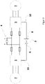
- a central motor 1 is provided as the electric motor, which acts on an axle 3 via a differential 2 .
- the central motor 1 is supplied with energy via an energy source 4 (usually HV battery), which supplies the central motor 1 with electrical energy via a converter 5, controlled by a drive control device 6.
- an energy source 4 usually HV battery
- the drive control unit 6 controls the two drives 7 each via a converter 5 assigned to the respective drive 7, wherein the function block containing the converter 5 can include further functional elements.
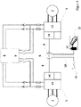
- FIG 3 shows an exemplary embodiment of a drive according to the invention with the implementation of emergency operation, with networking being provided there.
- Both wheel hub drives 7 have their own network as a respective subsystem. In detail, this means separate protection of the energy source 4 or the high-voltage DC voltage supply.
- two separate data bus interfaces 8 are provided on the central drive control unit 6 (CU) for the control.
- an alternative energy source to the energy source 4 (high-voltage battery) can be used to supply the drives.
- control line 10 in the low-voltage range from an emergency switch, not shown there, to the converter 5 of at least one wheel hub drive 7 and a power supply 4 to the same converter 5 is active.
- the control line 10 can be connected directly to the converter 5 via the drive control device 6 .
- the emergency operation switch can be connected to the converter via the CAN bus.
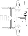
- Fig.4 shows a further exemplary embodiment of the drive according to the invention, an emergency energy source 9 being provided there in addition to the actual energy source 4 .
- the emergency energy source can be a high-voltage battery, with both the actual energy source 4 and the emergency energy source 9 being able to be assigned a battery management system (BMS).
- BMS battery management system
- the BMS can be part or sub-unit of the overall power supply arrangement.
- the arrangement of the energy source 4 and the emergency energy source 9 can be checked for complete or conditional functionality.
- a control line 10 in the low-voltage range leads from an emergency switch 11 to the converter 5 to at least one of the drives 7.
- the control line 10 leads from the emergency switch 11 via the axle drive control unit 6 to the converter 5.
- the same converter 5 is actively being supplied with energy, either via the actual energy source 4 or via the emergency energy source 9
- the control line 10 can be connected to the converter 5 via the drive control device 6 or directly. It can then be actuated in emergency mode via the gas pedal 12 and the direction switch 11 .
- an emergency voltage is connected or activated from the emergency energy source 9 via additional connection points, which provides the required energy for the power section 13 of the converter 5 .
- figure 5 shows another embodiment of a drive according to the invention. It includes the functional unit of the converter 5. In addition to the signal part 14, an additional area 15 is provided so that the emergency mode can be operated via a separate interface.
- the control current is in turn specified via the control line 10, the signal being triggered via a selector switch 11 or an analog value transmitter.
- the gas pedal 12 can be actuated conventionally in emergency operation.
Landscapes
- Engineering & Computer Science (AREA)
- Power Engineering (AREA)
- Transportation (AREA)
- Mechanical Engineering (AREA)
- Chemical & Material Sciences (AREA)
- Combustion & Propulsion (AREA)
- Life Sciences & Earth Sciences (AREA)
- Sustainable Development (AREA)
- Sustainable Energy (AREA)
- Electromagnetism (AREA)
- Physics & Mathematics (AREA)
- Electric Propulsion And Braking For Vehicles (AREA)
- Hybrid Electric Vehicles (AREA)
- Auxiliary Drives, Propulsion Controls, And Safety Devices (AREA)
- Axle Suspensions And Sidecars For Cycles (AREA)
- Lubricants (AREA)
Applications Claiming Priority (2)
| Application Number | Priority Date | Filing Date | Title |
|---|---|---|---|
| DE102016214275.5A DE102016214275A1 (de) | 2016-08-02 | 2016-08-02 | Elektrischer Traktionsantrieb für ein Fahrzeug |
| PCT/DE2017/200070 WO2018024296A1 (de) | 2016-08-02 | 2017-07-21 | Elektrischer traktionsantrieb für ein fahrzeug |
Publications (2)
| Publication Number | Publication Date |
|---|---|
| EP3325307A1 EP3325307A1 (de) | 2018-05-30 |
| EP3325307B1 true EP3325307B1 (de) | 2022-11-02 |
Family
ID=59811046
Family Applications (1)
| Application Number | Title | Priority Date | Filing Date |
|---|---|---|---|
| EP17764326.9A Active EP3325307B1 (de) | 2016-08-02 | 2017-07-21 | Elektrischer traktionsantrieb für ein fahrzeug |
Country Status (7)
| Country | Link |
|---|---|
| US (1) | US11351868B2 (pl) |
| EP (1) | EP3325307B1 (pl) |
| CN (1) | CN109562692B (pl) |
| DE (1) | DE102016214275A1 (pl) |
| ES (1) | ES2935975T3 (pl) |
| PL (1) | PL3325307T3 (pl) |
| WO (1) | WO2018024296A1 (pl) |
Families Citing this family (2)
| Publication number | Priority date | Publication date | Assignee | Title |
|---|---|---|---|---|
| DE102021125224A1 (de) | 2021-09-29 | 2023-03-30 | Schaeffler Technologies AG & Co. KG | Antriebssystem für ein Fahrzeug, Fahrzeug mit einem Antriebssystem, Verfahren zum Betrieb eines Fahrzeugs |
| CN118900055B (zh) * | 2023-05-04 | 2026-04-14 | 株洲中车时代电气股份有限公司 | 一种牵引变流器、控制方法、装置、设备、介质及系统 |
Citations (3)
| Publication number | Priority date | Publication date | Assignee | Title |
|---|---|---|---|---|
| DE19910091C1 (de) * | 1999-03-08 | 2000-08-03 | Daimler Chrysler Ag | Elektroantrieb |
| DE102005004330A1 (de) * | 2005-01-31 | 2006-08-10 | Robert Bosch Gmbh | Bordnetz für sicherheitsrelevante Verbraucher |
| WO2014048462A1 (de) * | 2012-09-26 | 2014-04-03 | Siemens Aktiengesellschaft | Antriebsanordnung für ein kraftfahrzeug |
Family Cites Families (3)
| Publication number | Priority date | Publication date | Assignee | Title |
|---|---|---|---|---|
| JP4473448B2 (ja) * | 1998-07-21 | 2010-06-02 | 株式会社東京アールアンドデー | ハイブリッド車両 |
| FR2921310B1 (fr) * | 2007-09-20 | 2011-04-29 | Michelin Soc Tech | Architecture materielle redondante pour l'etage de signaux de commande d'un systeme de freinage d'un vehicule dont toutes les roues sont reliees chacune a au moins une machine electrique rotative |
| DE102012216089A1 (de) * | 2012-09-11 | 2014-03-13 | Siemens Aktiengesellschaft | Verfahren und Steuereinheit zur Ansteuerung von Aktoren eines Fahrzeugs in einem Notbetrieb |
-
2016
- 2016-08-02 DE DE102016214275.5A patent/DE102016214275A1/de not_active Ceased
-
2017
- 2017-07-21 EP EP17764326.9A patent/EP3325307B1/de active Active
- 2017-07-21 CN CN201780048758.4A patent/CN109562692B/zh active Active
- 2017-07-21 PL PL17764326.9T patent/PL3325307T3/pl unknown
- 2017-07-21 ES ES17764326T patent/ES2935975T3/es active Active
- 2017-07-21 WO PCT/DE2017/200070 patent/WO2018024296A1/de not_active Ceased
- 2017-07-21 US US16/322,867 patent/US11351868B2/en active Active
Patent Citations (3)
| Publication number | Priority date | Publication date | Assignee | Title |
|---|---|---|---|---|
| DE19910091C1 (de) * | 1999-03-08 | 2000-08-03 | Daimler Chrysler Ag | Elektroantrieb |
| DE102005004330A1 (de) * | 2005-01-31 | 2006-08-10 | Robert Bosch Gmbh | Bordnetz für sicherheitsrelevante Verbraucher |
| WO2014048462A1 (de) * | 2012-09-26 | 2014-04-03 | Siemens Aktiengesellschaft | Antriebsanordnung für ein kraftfahrzeug |
Also Published As
| Publication number | Publication date |
|---|---|
| EP3325307A1 (de) | 2018-05-30 |
| US20190202294A1 (en) | 2019-07-04 |
| PL3325307T3 (pl) | 2023-03-06 |
| WO2018024296A1 (de) | 2018-02-08 |
| DE102016214275A1 (de) | 2018-02-08 |
| US11351868B2 (en) | 2022-06-07 |
| CN109562692B (zh) | 2022-06-07 |
| CN109562692A (zh) | 2019-04-02 |
| ES2935975T3 (es) | 2023-03-13 |
Similar Documents
| Publication | Publication Date | Title |
|---|---|---|
| DE102009046010B4 (de) | Hierarchisches Informationsanzeigesystem für ein Fahrzeug | |
| DE102015223612A1 (de) | System und Verfahren zur Steuerung der Degradation von Fahrzeugverbrauchern | |
| EP3121563B1 (de) | Verfahren und vorrichtung zur warnung vor dem liegenbleiben eines fahrzeuges | |
| DE102010052964A1 (de) | Verfahren zum Betreiben eines Fahrzeugs und Fahrerassistenzeinrichtung | |
| DE102008017699A1 (de) | System und Verfahren zur Bereitstellung von Streckeninformationen für einen Fahrer eines Fahrzeugs | |
| DE102017206694A1 (de) | Verfahren zur Assistenz eines Fahrmanövers und Assistenzsystem für ein Fahrmanöver | |
| DE102017206695A1 (de) | Fahrassistenzverfahren zur Assistenz eines leistungsintensiven Fahrmanövers eines Ego-Fahrzeugs und Fahrassistenzsystem für ein leistungsintensives Fahrmanöver eines Ego-Fahrzeugs | |
| DE102019100239A1 (de) | Verfahren und vorrichtungen zum unterstützen des entschärfens von fahrzeugblockaden an bahnübergängen | |
| DE102018115551A1 (de) | Verfahren zum Betreiben eines Fahrassistenzsystems eines Kraftfahrzeugs, wobei optisch eine Übergangsphase einer Verkehrssignalanlage erfasst wird, Fahrassistenzsystem sowie Kraftfahrzeug | |
| WO2017084951A1 (de) | Verfahren und vorrichtung zum assistierten, teilautomatisierten, hochautomatisierten, vollautomatisierten oder fahrerlosen fahren eines kraftfahrzeuges | |
| DE102018128565A1 (de) | Steuerungssystem und Steuerungsverfahren zum Anpassen einer Wiedergabe von visuellen Signalen für ein Fahrzeug mit Hybridantrieb | |
| DE102016216153A1 (de) | Verfahren und Vorrichtung zur situationsbasierten Warnung eines Fahrers eines Fahrzeugs | |
| EP3668747B1 (de) | Verfahren zum betreiben eines batteriemanagementsystems, batteriemanagementsystem und kraftfahrzeug | |
| EP3325307B1 (de) | Elektrischer traktionsantrieb für ein fahrzeug | |
| DE19914428C1 (de) | Antriebsanordnung für ein Kraftfahrzeug | |
| EP3760511A1 (de) | Verfahren zum betreiben eines fahrzeugs | |
| DE102010010557A1 (de) | Vorrichtung und Verfahren zum Betrieb eines Fahrerassistenzsystems für ein Fahrzeug | |
| DE102010007640A1 (de) | Gekoppeltes Achsantriebssystem für ein Fahrzeug | |
| DE102018205320B4 (de) | Antriebssystem zum elektromechanischen Antreiben eines mehrspurigen Fahrzeugs sowie entsprechendes mehrspuriges Fahrzeug | |
| DE102015014238A1 (de) | Vorrichtung und Verfahren für eine batteriedynamische Leistungsanzeige für ein Elektrofahrzeug | |
| DE102023108150B3 (de) | Brennstoffzellen-Fahrzeug und Verfahren zu dessen Betrieb | |
| DE102019217610A1 (de) | Verfahren zum Betrieb eines aus einem Zugfahrzeug und wenigstens einem Anhänger bestehenden Gespanns | |
| DE102019205924A1 (de) | Verfahren zum Betreiben eines Kraftfahrzeugs, Fahrerassistenzsystem und Kraftfahrzeug | |
| DE102018210412A1 (de) | Fahrerassistenzsystem mit einer Nothaltefunktion für ein Fahrzeug, Fahrzeug mit demselben und Verfahren zum Nothalten eines Fahrzeugs | |
| DE102008062636A1 (de) | Verfahren und Vorrichtung zur Änderung eines Höhenniveaus eines Fahrzeugs |
Legal Events
| Date | Code | Title | Description |
|---|---|---|---|
| STAA | Information on the status of an ep patent application or granted ep patent |
Free format text: STATUS: UNKNOWN |
|
| STAA | Information on the status of an ep patent application or granted ep patent |
Free format text: STATUS: THE INTERNATIONAL PUBLICATION HAS BEEN MADE |
|
| PUAI | Public reference made under article 153(3) epc to a published international application that has entered the european phase |
Free format text: ORIGINAL CODE: 0009012 |
|
| STAA | Information on the status of an ep patent application or granted ep patent |
Free format text: STATUS: REQUEST FOR EXAMINATION WAS MADE |
|
| 17P | Request for examination filed |
Effective date: 20180222 |
|
| AK | Designated contracting states |
Kind code of ref document: A1 Designated state(s): AL AT BE BG CH CY CZ DE DK EE ES FI FR GB GR HR HU IE IS IT LI LT LU LV MC MK MT NL NO PL PT RO RS SE SI SK SM TR |
|
| AX | Request for extension of the european patent |
Extension state: BA ME |
|
| STAA | Information on the status of an ep patent application or granted ep patent |
Free format text: STATUS: EXAMINATION IS IN PROGRESS |
|
| RIC1 | Information provided on ipc code assigned before grant |
Ipc: B60K 6/26 20071001ALI20180209BHEP Ipc: H02P 5/68 20060101ALI20180209BHEP Ipc: B60L 3/00 20190101AFI20180209BHEP Ipc: H02P 5/74 20060101ALI20180209BHEP Ipc: H02J 7/14 20060101ALI20180209BHEP Ipc: B60K 6/20 20071001ALI20180209BHEP |
|
| 17Q | First examination report despatched |
Effective date: 20190116 |
|
| DAV | Request for validation of the european patent (deleted) | ||
| DAX | Request for extension of the european patent (deleted) | ||
| GRAP | Despatch of communication of intention to grant a patent |
Free format text: ORIGINAL CODE: EPIDOSNIGR1 |
|
| STAA | Information on the status of an ep patent application or granted ep patent |
Free format text: STATUS: GRANT OF PATENT IS INTENDED |
|
| INTG | Intention to grant announced |
Effective date: 20220603 |
|
| GRAS | Grant fee paid |
Free format text: ORIGINAL CODE: EPIDOSNIGR3 |
|
| GRAA | (expected) grant |
Free format text: ORIGINAL CODE: 0009210 |
|
| STAA | Information on the status of an ep patent application or granted ep patent |
Free format text: STATUS: THE PATENT HAS BEEN GRANTED |
|
| AK | Designated contracting states |
Kind code of ref document: B1 Designated state(s): AL AT BE BG CH CY CZ DE DK EE ES FI FR GB GR HR HU IE IS IT LI LT LU LV MC MK MT NL NO PL PT RO RS SE SI SK SM TR |
|
| REG | Reference to a national code |
Ref country code: GB Ref legal event code: FG4D Free format text: NOT ENGLISH |
|
| REG | Reference to a national code |
Ref country code: CH Ref legal event code: EP Ref country code: AT Ref legal event code: REF Ref document number: 1528529 Country of ref document: AT Kind code of ref document: T Effective date: 20221115 |
|
| REG | Reference to a national code |
Ref country code: DE Ref legal event code: R096 Ref document number: 502017014048 Country of ref document: DE |
|
| REG | Reference to a national code |
Ref country code: IE Ref legal event code: FG4D Free format text: LANGUAGE OF EP DOCUMENT: GERMAN |
|
| REG | Reference to a national code |
Ref country code: NL Ref legal event code: FP |
|
| REG | Reference to a national code |
Ref country code: SE Ref legal event code: TRGR |
|
| REG | Reference to a national code |
Ref country code: LT Ref legal event code: MG9D |
|
| REG | Reference to a national code |
Ref country code: ES Ref legal event code: FG2A Ref document number: 2935975 Country of ref document: ES Kind code of ref document: T3 Effective date: 20230313 |
|
| PG25 | Lapsed in a contracting state [announced via postgrant information from national office to epo] |
Ref country code: PT Free format text: LAPSE BECAUSE OF FAILURE TO SUBMIT A TRANSLATION OF THE DESCRIPTION OR TO PAY THE FEE WITHIN THE PRESCRIBED TIME-LIMIT Effective date: 20230302 Ref country code: NO Free format text: LAPSE BECAUSE OF FAILURE TO SUBMIT A TRANSLATION OF THE DESCRIPTION OR TO PAY THE FEE WITHIN THE PRESCRIBED TIME-LIMIT Effective date: 20230202 Ref country code: LT Free format text: LAPSE BECAUSE OF FAILURE TO SUBMIT A TRANSLATION OF THE DESCRIPTION OR TO PAY THE FEE WITHIN THE PRESCRIBED TIME-LIMIT Effective date: 20221102 Ref country code: FI Free format text: LAPSE BECAUSE OF FAILURE TO SUBMIT A TRANSLATION OF THE DESCRIPTION OR TO PAY THE FEE WITHIN THE PRESCRIBED TIME-LIMIT Effective date: 20221102 |
|
| PG25 | Lapsed in a contracting state [announced via postgrant information from national office to epo] |
Ref country code: RS Free format text: LAPSE BECAUSE OF FAILURE TO SUBMIT A TRANSLATION OF THE DESCRIPTION OR TO PAY THE FEE WITHIN THE PRESCRIBED TIME-LIMIT Effective date: 20221102 Ref country code: LV Free format text: LAPSE BECAUSE OF FAILURE TO SUBMIT A TRANSLATION OF THE DESCRIPTION OR TO PAY THE FEE WITHIN THE PRESCRIBED TIME-LIMIT Effective date: 20221102 Ref country code: IS Free format text: LAPSE BECAUSE OF FAILURE TO SUBMIT A TRANSLATION OF THE DESCRIPTION OR TO PAY THE FEE WITHIN THE PRESCRIBED TIME-LIMIT Effective date: 20230302 Ref country code: HR Free format text: LAPSE BECAUSE OF FAILURE TO SUBMIT A TRANSLATION OF THE DESCRIPTION OR TO PAY THE FEE WITHIN THE PRESCRIBED TIME-LIMIT Effective date: 20221102 Ref country code: GR Free format text: LAPSE BECAUSE OF FAILURE TO SUBMIT A TRANSLATION OF THE DESCRIPTION OR TO PAY THE FEE WITHIN THE PRESCRIBED TIME-LIMIT Effective date: 20230203 |
|
| P01 | Opt-out of the competence of the unified patent court (upc) registered |
Effective date: 20230516 |
|
| PG25 | Lapsed in a contracting state [announced via postgrant information from national office to epo] |
Ref country code: SM Free format text: LAPSE BECAUSE OF FAILURE TO SUBMIT A TRANSLATION OF THE DESCRIPTION OR TO PAY THE FEE WITHIN THE PRESCRIBED TIME-LIMIT Effective date: 20221102 Ref country code: RO Free format text: LAPSE BECAUSE OF FAILURE TO SUBMIT A TRANSLATION OF THE DESCRIPTION OR TO PAY THE FEE WITHIN THE PRESCRIBED TIME-LIMIT Effective date: 20221102 Ref country code: EE Free format text: LAPSE BECAUSE OF FAILURE TO SUBMIT A TRANSLATION OF THE DESCRIPTION OR TO PAY THE FEE WITHIN THE PRESCRIBED TIME-LIMIT Effective date: 20221102 Ref country code: DK Free format text: LAPSE BECAUSE OF FAILURE TO SUBMIT A TRANSLATION OF THE DESCRIPTION OR TO PAY THE FEE WITHIN THE PRESCRIBED TIME-LIMIT Effective date: 20221102 Ref country code: CZ Free format text: LAPSE BECAUSE OF FAILURE TO SUBMIT A TRANSLATION OF THE DESCRIPTION OR TO PAY THE FEE WITHIN THE PRESCRIBED TIME-LIMIT Effective date: 20221102 |
|
| REG | Reference to a national code |
Ref country code: DE Ref legal event code: R097 Ref document number: 502017014048 Country of ref document: DE |
|
| PG25 | Lapsed in a contracting state [announced via postgrant information from national office to epo] |
Ref country code: SK Free format text: LAPSE BECAUSE OF FAILURE TO SUBMIT A TRANSLATION OF THE DESCRIPTION OR TO PAY THE FEE WITHIN THE PRESCRIBED TIME-LIMIT Effective date: 20221102 Ref country code: AL Free format text: LAPSE BECAUSE OF FAILURE TO SUBMIT A TRANSLATION OF THE DESCRIPTION OR TO PAY THE FEE WITHIN THE PRESCRIBED TIME-LIMIT Effective date: 20221102 |
|
| PLBE | No opposition filed within time limit |
Free format text: ORIGINAL CODE: 0009261 |
|
| STAA | Information on the status of an ep patent application or granted ep patent |
Free format text: STATUS: NO OPPOSITION FILED WITHIN TIME LIMIT |
|
| 26N | No opposition filed |
Effective date: 20230803 |
|
| PG25 | Lapsed in a contracting state [announced via postgrant information from national office to epo] |
Ref country code: SI Free format text: LAPSE BECAUSE OF FAILURE TO SUBMIT A TRANSLATION OF THE DESCRIPTION OR TO PAY THE FEE WITHIN THE PRESCRIBED TIME-LIMIT Effective date: 20221102 |
|
| PG25 | Lapsed in a contracting state [announced via postgrant information from national office to epo] |
Ref country code: MC Free format text: LAPSE BECAUSE OF FAILURE TO SUBMIT A TRANSLATION OF THE DESCRIPTION OR TO PAY THE FEE WITHIN THE PRESCRIBED TIME-LIMIT Effective date: 20221102 |
|
| PG25 | Lapsed in a contracting state [announced via postgrant information from national office to epo] |
Ref country code: MC Free format text: LAPSE BECAUSE OF FAILURE TO SUBMIT A TRANSLATION OF THE DESCRIPTION OR TO PAY THE FEE WITHIN THE PRESCRIBED TIME-LIMIT Effective date: 20221102 |
|
| REG | Reference to a national code |
Ref country code: CH Ref legal event code: PL |
|
| REG | Reference to a national code |
Ref country code: SE Ref legal event code: EUG |
|
| REG | Reference to a national code |
Ref country code: NL Ref legal event code: MM Effective date: 20230801 |
|
| REG | Reference to a national code |
Ref country code: BE Ref legal event code: MM Effective date: 20230731 |
|
| PG25 | Lapsed in a contracting state [announced via postgrant information from national office to epo] |
Ref country code: LU Free format text: LAPSE BECAUSE OF NON-PAYMENT OF DUE FEES Effective date: 20230721 |
|
| PG25 | Lapsed in a contracting state [announced via postgrant information from national office to epo] |
Ref country code: LU Free format text: LAPSE BECAUSE OF NON-PAYMENT OF DUE FEES Effective date: 20230721 |
|
| PG25 | Lapsed in a contracting state [announced via postgrant information from national office to epo] |
Ref country code: NL Free format text: LAPSE BECAUSE OF NON-PAYMENT OF DUE FEES Effective date: 20230801 |
|
| REG | Reference to a national code |
Ref country code: IE Ref legal event code: MM4A |
|
| PG25 | Lapsed in a contracting state [announced via postgrant information from national office to epo] |
Ref country code: NL Free format text: LAPSE BECAUSE OF NON-PAYMENT OF DUE FEES Effective date: 20230801 Ref country code: CH Free format text: LAPSE BECAUSE OF NON-PAYMENT OF DUE FEES Effective date: 20230731 |
|
| PG25 | Lapsed in a contracting state [announced via postgrant information from national office to epo] |
Ref country code: SE Free format text: LAPSE BECAUSE OF NON-PAYMENT OF DUE FEES Effective date: 20230722 Ref country code: BE Free format text: LAPSE BECAUSE OF NON-PAYMENT OF DUE FEES Effective date: 20230731 |
|
| PG25 | Lapsed in a contracting state [announced via postgrant information from national office to epo] |
Ref country code: IE Free format text: LAPSE BECAUSE OF NON-PAYMENT OF DUE FEES Effective date: 20230721 |
|
| PG25 | Lapsed in a contracting state [announced via postgrant information from national office to epo] |
Ref country code: IT Free format text: LAPSE BECAUSE OF NON-PAYMENT OF DUE FEES Effective date: 20230721 Ref country code: IE Free format text: LAPSE BECAUSE OF NON-PAYMENT OF DUE FEES Effective date: 20230721 |
|
| REG | Reference to a national code |
Ref country code: AT Ref legal event code: MM01 Ref document number: 1528529 Country of ref document: AT Kind code of ref document: T Effective date: 20230721 |
|
| PGFP | Annual fee paid to national office [announced via postgrant information from national office to epo] |
Ref country code: DE Payment date: 20240927 Year of fee payment: 8 |
|
| PGFP | Annual fee paid to national office [announced via postgrant information from national office to epo] |
Ref country code: GB Payment date: 20240723 Year of fee payment: 8 |
|
| PGFP | Annual fee paid to national office [announced via postgrant information from national office to epo] |
Ref country code: FR Payment date: 20240724 Year of fee payment: 8 |
|
| PGFP | Annual fee paid to national office [announced via postgrant information from national office to epo] |
Ref country code: ES Payment date: 20240816 Year of fee payment: 8 |
|
| PG25 | Lapsed in a contracting state [announced via postgrant information from national office to epo] |
Ref country code: AT Free format text: LAPSE BECAUSE OF NON-PAYMENT OF DUE FEES Effective date: 20230721 |
|
| PGFP | Annual fee paid to national office [announced via postgrant information from national office to epo] |
Ref country code: PL Payment date: 20240715 Year of fee payment: 8 |
|
| PG25 | Lapsed in a contracting state [announced via postgrant information from national office to epo] |
Ref country code: AT Free format text: LAPSE BECAUSE OF NON-PAYMENT OF DUE FEES Effective date: 20230721 |
|
| PG25 | Lapsed in a contracting state [announced via postgrant information from national office to epo] |
Ref country code: BG Free format text: LAPSE BECAUSE OF FAILURE TO SUBMIT A TRANSLATION OF THE DESCRIPTION OR TO PAY THE FEE WITHIN THE PRESCRIBED TIME-LIMIT Effective date: 20221102 |
|
| PG25 | Lapsed in a contracting state [announced via postgrant information from national office to epo] |
Ref country code: BG Free format text: LAPSE BECAUSE OF FAILURE TO SUBMIT A TRANSLATION OF THE DESCRIPTION OR TO PAY THE FEE WITHIN THE PRESCRIBED TIME-LIMIT Effective date: 20221102 |
|
| PG25 | Lapsed in a contracting state [announced via postgrant information from national office to epo] |
Ref country code: CY Free format text: LAPSE BECAUSE OF FAILURE TO SUBMIT A TRANSLATION OF THE DESCRIPTION OR TO PAY THE FEE WITHIN THE PRESCRIBED TIME-LIMIT; INVALID AB INITIO Effective date: 20170721 |
|
| PG25 | Lapsed in a contracting state [announced via postgrant information from national office to epo] |
Ref country code: HU Free format text: LAPSE BECAUSE OF FAILURE TO SUBMIT A TRANSLATION OF THE DESCRIPTION OR TO PAY THE FEE WITHIN THE PRESCRIBED TIME-LIMIT; INVALID AB INITIO Effective date: 20170721 |
|
| REG | Reference to a national code |
Ref country code: DE Ref legal event code: R119 Ref document number: 502017014048 Country of ref document: DE |
|
| GBPC | Gb: european patent ceased through non-payment of renewal fee |
Effective date: 20250721 |
|
| PG25 | Lapsed in a contracting state [announced via postgrant information from national office to epo] |
Ref country code: GB Free format text: LAPSE BECAUSE OF NON-PAYMENT OF DUE FEES Effective date: 20250721 |
|
| PG25 | Lapsed in a contracting state [announced via postgrant information from national office to epo] |
Ref country code: DE Free format text: LAPSE BECAUSE OF NON-PAYMENT OF DUE FEES Effective date: 20260203 |
|
| PG25 | Lapsed in a contracting state [announced via postgrant information from national office to epo] |
Ref country code: FR Free format text: LAPSE BECAUSE OF NON-PAYMENT OF DUE FEES Effective date: 20250731 |