EP3325307B1 - Elektrischer traktionsantrieb für ein fahrzeug - Google Patents
Elektrischer traktionsantrieb für ein fahrzeug Download PDFInfo
- Publication number
- EP3325307B1 EP3325307B1 EP17764326.9A EP17764326A EP3325307B1 EP 3325307 B1 EP3325307 B1 EP 3325307B1 EP 17764326 A EP17764326 A EP 17764326A EP 3325307 B1 EP3325307 B1 EP 3325307B1
- Authority
- EP
- European Patent Office
- Prior art keywords
- emergency operation
- emergency
- drive
- drive according
- operation function
- Prior art date
- Legal status (The legal status is an assumption and is not a legal conclusion. Google has not performed a legal analysis and makes no representation as to the accuracy of the status listed.)
- Active
Links
- 230000006855 networking Effects 0.000 claims description 11
- 230000004913 activation Effects 0.000 claims description 3
- 230000005540 biological transmission Effects 0.000 description 2
- 238000002485 combustion reaction Methods 0.000 description 2
- 230000007547 defect Effects 0.000 description 2
- 238000004804 winding Methods 0.000 description 2
- 230000003213 activating effect Effects 0.000 description 1
- 238000010276 construction Methods 0.000 description 1
- 230000002950 deficient Effects 0.000 description 1
- 238000001514 detection method Methods 0.000 description 1
- 238000011161 development Methods 0.000 description 1
- 230000018109 developmental process Effects 0.000 description 1
- 230000007246 mechanism Effects 0.000 description 1
- 230000001960 triggered effect Effects 0.000 description 1
Images


Classifications
-
- B—PERFORMING OPERATIONS; TRANSPORTING
- B60—VEHICLES IN GENERAL
- B60L—PROPULSION OF ELECTRICALLY-PROPELLED VEHICLES; SUPPLYING ELECTRIC POWER FOR AUXILIARY EQUIPMENT OF ELECTRICALLY-PROPELLED VEHICLES; ELECTRODYNAMIC BRAKE SYSTEMS FOR VEHICLES IN GENERAL; MAGNETIC SUSPENSION OR LEVITATION FOR VEHICLES; MONITORING OPERATING VARIABLES OF ELECTRICALLY-PROPELLED VEHICLES; ELECTRIC SAFETY DEVICES FOR ELECTRICALLY-PROPELLED VEHICLES
- B60L3/00—Electric devices on electrically-propelled vehicles for safety purposes; Monitoring operating variables, e.g. speed, deceleration or energy consumption
- B60L3/0092—Electric devices on electrically-propelled vehicles for safety purposes; Monitoring operating variables, e.g. speed, deceleration or energy consumption with use of redundant elements for safety purposes
-
- B—PERFORMING OPERATIONS; TRANSPORTING
- B60—VEHICLES IN GENERAL
- B60K—ARRANGEMENT OR MOUNTING OF PROPULSION UNITS OR OF TRANSMISSIONS IN VEHICLES; ARRANGEMENT OR MOUNTING OF PLURAL DIVERSE PRIME-MOVERS IN VEHICLES; AUXILIARY DRIVES FOR VEHICLES; INSTRUMENTATION OR DASHBOARDS FOR VEHICLES; ARRANGEMENTS IN CONNECTION WITH COOLING, AIR INTAKE, GAS EXHAUST OR FUEL SUPPLY OF PROPULSION UNITS IN VEHICLES
- B60K6/00—Arrangement or mounting of plural diverse prime-movers for mutual or common propulsion, e.g. hybrid propulsion systems comprising electric motors and internal combustion engines ; Control systems therefor, i.e. systems controlling two or more prime movers, or controlling one of these prime movers and any of the transmission, drive or drive units Informative references: mechanical gearings with secondary electric drive F16H3/72; arrangements for handling mechanical energy structurally associated with the dynamo-electric machine H02K7/00; machines comprising structurally interrelated motor and generator parts H02K51/00; dynamo-electric machines not otherwise provided for in H02K see H02K99/00
- B60K6/20—Arrangement or mounting of plural diverse prime-movers for mutual or common propulsion, e.g. hybrid propulsion systems comprising electric motors and internal combustion engines ; Control systems therefor, i.e. systems controlling two or more prime movers, or controlling one of these prime movers and any of the transmission, drive or drive units Informative references: mechanical gearings with secondary electric drive F16H3/72; arrangements for handling mechanical energy structurally associated with the dynamo-electric machine H02K7/00; machines comprising structurally interrelated motor and generator parts H02K51/00; dynamo-electric machines not otherwise provided for in H02K see H02K99/00 the prime-movers consisting of electric motors and internal combustion engines, e.g. HEVs
-
- B—PERFORMING OPERATIONS; TRANSPORTING
- B60—VEHICLES IN GENERAL
- B60L—PROPULSION OF ELECTRICALLY-PROPELLED VEHICLES; SUPPLYING ELECTRIC POWER FOR AUXILIARY EQUIPMENT OF ELECTRICALLY-PROPELLED VEHICLES; ELECTRODYNAMIC BRAKE SYSTEMS FOR VEHICLES IN GENERAL; MAGNETIC SUSPENSION OR LEVITATION FOR VEHICLES; MONITORING OPERATING VARIABLES OF ELECTRICALLY-PROPELLED VEHICLES; ELECTRIC SAFETY DEVICES FOR ELECTRICALLY-PROPELLED VEHICLES
- B60L7/00—Electrodynamic brake systems for vehicles in general
- B60L7/24—Electrodynamic brake systems for vehicles in general with additional mechanical or electromagnetic braking
- B60L7/26—Controlling the braking effect
-
- B—PERFORMING OPERATIONS; TRANSPORTING
- B62—LAND VEHICLES FOR TRAVELLING OTHERWISE THAN ON RAILS
- B62D—MOTOR VEHICLES; TRAILERS
- B62D63/00—Motor vehicles or trailers not otherwise provided for
- B62D63/02—Motor vehicles
- B62D63/04—Component parts or accessories
-
- H—ELECTRICITY
- H02—GENERATION; CONVERSION OR DISTRIBUTION OF ELECTRIC POWER
- H02K—DYNAMO-ELECTRIC MACHINES
- H02K7/00—Arrangements for handling mechanical energy structurally associated with dynamo-electric machines, e.g. structural association with mechanical driving motors or auxiliary dynamo-electric machines
- H02K7/10—Structural association with clutches, brakes, gears, pulleys or mechanical starters
- H02K7/116—Structural association with clutches, brakes, gears, pulleys or mechanical starters with gears
-
- H—ELECTRICITY
- H02—GENERATION; CONVERSION OR DISTRIBUTION OF ELECTRIC POWER
- H02P—CONTROL OR REGULATION OF ELECTRIC MOTORS, ELECTRIC GENERATORS OR DYNAMO-ELECTRIC CONVERTERS; CONTROLLING TRANSFORMERS, REACTORS OR CHOKE COILS
- H02P5/00—Arrangements specially adapted for regulating or controlling the speed or torque of two or more electric motors
- H02P5/68—Arrangements specially adapted for regulating or controlling the speed or torque of two or more electric motors controlling two or more dc dynamo-electric motors
- H02P5/69—Arrangements specially adapted for regulating or controlling the speed or torque of two or more electric motors controlling two or more dc dynamo-electric motors mechanically coupled by gearing
- H02P5/695—Differential gearing
-
- H—ELECTRICITY
- H02—GENERATION; CONVERSION OR DISTRIBUTION OF ELECTRIC POWER
- H02P—CONTROL OR REGULATION OF ELECTRIC MOTORS, ELECTRIC GENERATORS OR DYNAMO-ELECTRIC CONVERTERS; CONTROLLING TRANSFORMERS, REACTORS OR CHOKE COILS
- H02P5/00—Arrangements specially adapted for regulating or controlling the speed or torque of two or more electric motors
- H02P5/74—Arrangements specially adapted for regulating or controlling the speed or torque of two or more electric motors controlling two or more ac dynamo-electric motors
-
- B—PERFORMING OPERATIONS; TRANSPORTING
- B60—VEHICLES IN GENERAL
- B60K—ARRANGEMENT OR MOUNTING OF PROPULSION UNITS OR OF TRANSMISSIONS IN VEHICLES; ARRANGEMENT OR MOUNTING OF PLURAL DIVERSE PRIME-MOVERS IN VEHICLES; AUXILIARY DRIVES FOR VEHICLES; INSTRUMENTATION OR DASHBOARDS FOR VEHICLES; ARRANGEMENTS IN CONNECTION WITH COOLING, AIR INTAKE, GAS EXHAUST OR FUEL SUPPLY OF PROPULSION UNITS IN VEHICLES
- B60K6/00—Arrangement or mounting of plural diverse prime-movers for mutual or common propulsion, e.g. hybrid propulsion systems comprising electric motors and internal combustion engines ; Control systems therefor, i.e. systems controlling two or more prime movers, or controlling one of these prime movers and any of the transmission, drive or drive units Informative references: mechanical gearings with secondary electric drive F16H3/72; arrangements for handling mechanical energy structurally associated with the dynamo-electric machine H02K7/00; machines comprising structurally interrelated motor and generator parts H02K51/00; dynamo-electric machines not otherwise provided for in H02K see H02K99/00
- B60K6/20—Arrangement or mounting of plural diverse prime-movers for mutual or common propulsion, e.g. hybrid propulsion systems comprising electric motors and internal combustion engines ; Control systems therefor, i.e. systems controlling two or more prime movers, or controlling one of these prime movers and any of the transmission, drive or drive units Informative references: mechanical gearings with secondary electric drive F16H3/72; arrangements for handling mechanical energy structurally associated with the dynamo-electric machine H02K7/00; machines comprising structurally interrelated motor and generator parts H02K51/00; dynamo-electric machines not otherwise provided for in H02K see H02K99/00 the prime-movers consisting of electric motors and internal combustion engines, e.g. HEVs
- B60K6/22—Arrangement or mounting of plural diverse prime-movers for mutual or common propulsion, e.g. hybrid propulsion systems comprising electric motors and internal combustion engines ; Control systems therefor, i.e. systems controlling two or more prime movers, or controlling one of these prime movers and any of the transmission, drive or drive units Informative references: mechanical gearings with secondary electric drive F16H3/72; arrangements for handling mechanical energy structurally associated with the dynamo-electric machine H02K7/00; machines comprising structurally interrelated motor and generator parts H02K51/00; dynamo-electric machines not otherwise provided for in H02K see H02K99/00 the prime-movers consisting of electric motors and internal combustion engines, e.g. HEVs characterised by apparatus, components or means specially adapted for HEVs
- B60K6/26—Arrangement or mounting of plural diverse prime-movers for mutual or common propulsion, e.g. hybrid propulsion systems comprising electric motors and internal combustion engines ; Control systems therefor, i.e. systems controlling two or more prime movers, or controlling one of these prime movers and any of the transmission, drive or drive units Informative references: mechanical gearings with secondary electric drive F16H3/72; arrangements for handling mechanical energy structurally associated with the dynamo-electric machine H02K7/00; machines comprising structurally interrelated motor and generator parts H02K51/00; dynamo-electric machines not otherwise provided for in H02K see H02K99/00 the prime-movers consisting of electric motors and internal combustion engines, e.g. HEVs characterised by apparatus, components or means specially adapted for HEVs characterised by the motors or the generators
- B60K2006/266—Arrangement or mounting of plural diverse prime-movers for mutual or common propulsion, e.g. hybrid propulsion systems comprising electric motors and internal combustion engines ; Control systems therefor, i.e. systems controlling two or more prime movers, or controlling one of these prime movers and any of the transmission, drive or drive units Informative references: mechanical gearings with secondary electric drive F16H3/72; arrangements for handling mechanical energy structurally associated with the dynamo-electric machine H02K7/00; machines comprising structurally interrelated motor and generator parts H02K51/00; dynamo-electric machines not otherwise provided for in H02K see H02K99/00 the prime-movers consisting of electric motors and internal combustion engines, e.g. HEVs characterised by apparatus, components or means specially adapted for HEVs characterised by the motors or the generators with two coaxial motors or generators
-
- B—PERFORMING OPERATIONS; TRANSPORTING
- B60—VEHICLES IN GENERAL
- B60L—PROPULSION OF ELECTRICALLY-PROPELLED VEHICLES; SUPPLYING ELECTRIC POWER FOR AUXILIARY EQUIPMENT OF ELECTRICALLY-PROPELLED VEHICLES; ELECTRODYNAMIC BRAKE SYSTEMS FOR VEHICLES IN GENERAL; MAGNETIC SUSPENSION OR LEVITATION FOR VEHICLES; MONITORING OPERATING VARIABLES OF ELECTRICALLY-PROPELLED VEHICLES; ELECTRIC SAFETY DEVICES FOR ELECTRICALLY-PROPELLED VEHICLES
- B60L2220/00—Electrical machine types; Structures or applications thereof
- B60L2220/40—Electrical machine applications
- B60L2220/44—Wheel Hub motors, i.e. integrated in the wheel hub
-
- H—ELECTRICITY
- H02—GENERATION; CONVERSION OR DISTRIBUTION OF ELECTRIC POWER
- H02J—CIRCUIT ARRANGEMENTS OR SYSTEMS FOR SUPPLYING OR DISTRIBUTING ELECTRIC POWER; SYSTEMS FOR STORING ELECTRIC ENERGY
- H02J7/00—Circuit arrangements for charging or depolarising batteries or for supplying loads from batteries
- H02J7/14—Circuit arrangements for charging or depolarising batteries or for supplying loads from batteries for charging batteries from dynamo-electric generators driven at varying speed, e.g. on vehicle
- H02J7/143—Circuit arrangements for charging or depolarising batteries or for supplying loads from batteries for charging batteries from dynamo-electric generators driven at varying speed, e.g. on vehicle with multiple generators
-
- Y—GENERAL TAGGING OF NEW TECHNOLOGICAL DEVELOPMENTS; GENERAL TAGGING OF CROSS-SECTIONAL TECHNOLOGIES SPANNING OVER SEVERAL SECTIONS OF THE IPC; TECHNICAL SUBJECTS COVERED BY FORMER USPC CROSS-REFERENCE ART COLLECTIONS [XRACs] AND DIGESTS
- Y02—TECHNOLOGIES OR APPLICATIONS FOR MITIGATION OR ADAPTATION AGAINST CLIMATE CHANGE
- Y02T—CLIMATE CHANGE MITIGATION TECHNOLOGIES RELATED TO TRANSPORTATION
- Y02T10/00—Road transport of goods or passengers
- Y02T10/60—Other road transportation technologies with climate change mitigation effect
- Y02T10/64—Electric machine technologies in electromobility
Definitions
- the present invention relates to an electric traction drive for a vehicle, having at least two individual wheel drives that can be controlled independently of one another.
- vehicle is to be understood in the broadest sense, whereby it is predominantly a question here of passenger vehicles, including buses, and commercial vehicles, including special-purpose vehicles.
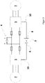
- Hybrid vehicles usually include an electric central motor as well as a transmission and a differential in addition to the internal combustion engine.
- the central motor is supplied with electrical energy via a high-voltage battery and a converter.
- a control unit is used to control the central motor.
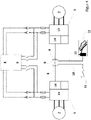
- Electric single-wheel drives with gear ratios and gearless single-wheel drives as direct drives are also already known from practice, namely so-called wheel hub motors. They are used in the area of passenger cars as well as in the area of commercial vehicles and buses as well as in special vehicles.
- wheel hub drives are integrated into the drive train and the individual wheel drives are protected centrally and controlled via a single interface on the drive control unit (cf. figure 2 ).
- Reliable emergency operation is therefore not possible because, for example, a fault in the power supply can deactivate both drives.
- a fault in the data bus line would also lead to a loss of function of both drives. According to the state of the art, genuine emergency operation is therefore not possible.
- the document WO 2014/048462 A1 discloses a drive arrangement for a motor vehicle and a corresponding motor vehicle.
- the pamphlet DE 10 2005 004 330 A1 relates to an on-board network for safety-relevant consumers.
- the object of the present invention is to provide an electric traction drive for a vehicle with individually driven wheels, which enables emergency operation using simple means and without any special design effort, in order to prevent the vehicle from breaking down.
- the limp home function should at least make it possible to drive the vehicle independently out of the danger zone. Ideally, it should be possible to drive the vehicle to the nearest service workshop independently.
- an electric traction drive for a vehicle with at least two independently controllable single-wheel drives, is characterized by two individually driven wheels on one axle and a common energy source for the two individually driven wheels on the axle, with the drives being redundant in order to implement an emergency running function , the two individual wheel drives each having their own control and/or power-related network in the sense of a subsystem, and each subsystem comprising a separate data bus interface on a central axle drive control unit (6) for controlling the individual wheel drives.
- the emergency operation function is implemented in that the drives are redundantly functional. This means that at least if both individual wheel drives are not defective at the same time, one of the drives can work in emergency mode.
- the two individual wheel drives each have their own control and/or power-related networking in the sense of a subsystem.
- the network or each subsystem includes a separate data bus interface on a central axle drive control unit, namely for the direct or indirect activation of the respective individual wheel drives. To this extent, the dependency on a single data bus line is eliminated.
- the network or the subsystem can include an emergency energy source that provides the required energy for the power section of a respective converter.
- the emergency energy source can be an energy generator or the energy generator can be part of the emergency energy source. This can be a generator, solar cells, etc.
- the emergency energy source can preferably be an accumulator or a battery that is provided in a smaller design and with lower power.
- the emergency energy source is used to supply voltage or power to the individual wheel drives in emergency operation, with this being reduced in terms of performance, especially since the emergency energy source is used exclusively to ensure the emergency function.
- the emergency energy source causes asymmetric traction or the drive of a single drive wheel in order to move the vehicle independently out of the danger area or to drive it to the next service workshop at reduced speed.
- the emergency function i.e. emergency operation
- the detection can take place, for example, from a control unit or a battery management system.
- the emergency operation function i.e. the emergency operation mode
- the emergency operation function can be activated manually by the driver of the vehicle using a switch, button, etc., namely when the damage/defect has occurred.
- the emergency function for example, the emergency energy source and/or the special control mechanisms of the subsystem causing the emergency function are activated.
- the direction of travel can be selected with or after activation of the limp home function, so that the vehicle is sufficiently manoeuvrable.
- the gas pedal can be used for the usual actuation or can act on a suitable switching or control device (lever, etc.).
- a low-voltage signal activating the emergency function can be routed to the converter and at least one of the individual drives via a control line directly or via the axle drive control unit. It is essential that the same converter is actively supplied with energy, possibly from the emergency energy source.
- the actual driving operation is implemented via a control current in the converter, with the amount of the control current being able to be stored in software assigned to the converter.
- the subsystem of the emergency operation function also accesses this software in order to ensure an adequate energy supply in emergency operation.
- the emergency function is implemented predominantly or completely via software. Accordingly, it can be retrofitted in existing drives.
- the algorithm of the emergency function is stored entirely or at least partially as software in the converter control unit, in an original or a redundant secondary hardware area.
- the emergency function in particular the algorithms of the emergency function, to be stored entirely or at least partially as software in the battery management system.
- a central motor 1 is provided as the electric motor, which acts on an axle 3 via a differential 2 .
- the central motor 1 is supplied with energy via an energy source 4 (usually HV battery), which supplies the central motor 1 with electrical energy via a converter 5, controlled by a drive control device 6.
- an energy source 4 usually HV battery
- the drive control unit 6 controls the two drives 7 each via a converter 5 assigned to the respective drive 7, wherein the function block containing the converter 5 can include further functional elements.
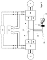
- FIG 3 shows an exemplary embodiment of a drive according to the invention with the implementation of emergency operation, with networking being provided there.
- Both wheel hub drives 7 have their own network as a respective subsystem. In detail, this means separate protection of the energy source 4 or the high-voltage DC voltage supply.
- two separate data bus interfaces 8 are provided on the central drive control unit 6 (CU) for the control.
- an alternative energy source to the energy source 4 (high-voltage battery) can be used to supply the drives.
- control line 10 in the low-voltage range from an emergency switch, not shown there, to the converter 5 of at least one wheel hub drive 7 and a power supply 4 to the same converter 5 is active.
- the control line 10 can be connected directly to the converter 5 via the drive control device 6 .
- the emergency operation switch can be connected to the converter via the CAN bus.
- Fig.4 shows a further exemplary embodiment of the drive according to the invention, an emergency energy source 9 being provided there in addition to the actual energy source 4 .
- the emergency energy source can be a high-voltage battery, with both the actual energy source 4 and the emergency energy source 9 being able to be assigned a battery management system (BMS).
- BMS battery management system
- the BMS can be part or sub-unit of the overall power supply arrangement.
- the arrangement of the energy source 4 and the emergency energy source 9 can be checked for complete or conditional functionality.
- a control line 10 in the low-voltage range leads from an emergency switch 11 to the converter 5 to at least one of the drives 7.
- the control line 10 leads from the emergency switch 11 via the axle drive control unit 6 to the converter 5.
- the same converter 5 is actively being supplied with energy, either via the actual energy source 4 or via the emergency energy source 9
- the control line 10 can be connected to the converter 5 via the drive control device 6 or directly. It can then be actuated in emergency mode via the gas pedal 12 and the direction switch 11 .
- an emergency voltage is connected or activated from the emergency energy source 9 via additional connection points, which provides the required energy for the power section 13 of the converter 5 .
- figure 5 shows another embodiment of a drive according to the invention. It includes the functional unit of the converter 5. In addition to the signal part 14, an additional area 15 is provided so that the emergency mode can be operated via a separate interface.
- the control current is in turn specified via the control line 10, the signal being triggered via a selector switch 11 or an analog value transmitter.
- the gas pedal 12 can be actuated conventionally in emergency operation.
Description
- Die vorliegende Erfindung betrifft einen elektrischen Traktionsantrieb für ein Fahrzeug, mit mindestens zwei unabhängig voneinander ansteuerbaren Einzelradantrieben.
- Der Begriff "Fahrzeug" ist im weitesten Sinne zu verstehen, wobei es hier ganz überwiegend um Personenfahrzeuge, inklusive Omnibusse sowie um Nutzfahrzeuge, inklusive Sonderfahrzeuge geht.
- Tritt in hybrid- oder batterieelektrischen Fahrzeugen ein Schaden im Antriebssystem auf, insbesondere an einem Verbrennungsmotor, einem Elektromotor, dem Getriebe, dem Differenzial, einem Umrichter oder an der Hochvoltbatterie, lässt sich das Fahrzeug nicht mehr von der Stelle bewegen und wird als so genannter "Liegenbleiber" bezeichnet. Solche "Liegenbleiber" stellen ein Hindernis und eine Gefahr im Straßenverkehr dar. Das erforderliche Abschleppen bedingt zudem erhebliche Kosten.
- Hybridfahrzeuge umfassen üblicherweise zum Verbrennungsmotor einen elektrischen Zentralmotor sowie ein Getriebe und ein Differenzial. Zum diesbezüglichen Stand der Technik sei auf
Figur 1 verwiesen. Der Zentralmotor wird über eine Hochvoltbatterie und einen Umrichter mit elektrischer Energie versorgt. Ein Steuergerät dient zur Ansteuerung des Zentralmotors. - Aus der Praxis sind auch bereits elektrische Einzelradantriebe mit Getriebeübersetzung und getriebelose Einzelradantriebe als Direktantrieb bekannt, nämlich sogenannte Radnabenmotoren. Sie finden sowohl im Bereich der Personenkraftwagen als auch im Bereich der Nutzfahrzeuge und Omnibusse sowie bei Sonderfahrzeugen ihren Einsatz.
- Ungeachtet der konkreten Ausführung ist bei einem Schaden im Antriebssystem eine Weiterfahrt aus fahrzeugeigenem Antrieb nicht mehr möglich, beispielsweise aufgrund einer Blockade rotierender Teile im Antriebsstrang. Das liegengebliebene Fahrzeug muss daher abgeschleppt oder vor Ort instandgesetzt werden. Insbesondere an Gefahrenstellen wie unübersichtlichen Kurven, an Baustellen, auf mehrspurigen Kraftfahrstraßen/Schnellstraßen/Autobahnen, an Bahnübergängen, etc. bedeutet dies eine Gefahr für Fahrer, Insassen und Dritte.
- Aus dem aus der Praxis bekannten Stand der Technik ist die einfache Vernetzung sogenannter Radnabenantriebe bekannt. Sie sind in den Antriebsstrang integriert und es erfolgt eine zentrale Absicherung der Einzelradantriebe sowie eine Ansteuerung über eine einzige Schnittstelle am Steuergerät des Antriebs (vgl.
Figur 2 ). Ein zuverlässiger Notlaufbetrieb ist damit nicht möglich, da beispielsweise ein Fehler in der Stromversorgung beide Antriebe deaktivieren kann. Ein Fehler in der Datenbus-Leitung würde ebenfalls zu einem Funktionsverlust beider Antriebe führen. Ein echter Notlaufbetrieb ist gemäß Stand der Technik daher nicht möglich. - Des Weiteren ist aus der
DE 199 10 091 C1 ein Elektroantrieb mit einem Elektromotor und einer Motorelektronik bekannt, wobei der Strom für den Elektromotor von einer Stromquelle erzeugt wird, wobei mindestens zwei voneinander unabhängige Stromquellen vorgesehen sind. Jeder Stromquelle ist eine Elektromotorwicklung zugeordnet, wobei zum Beispiel ein Elektromotor zwei parallele Wicklungen aufweist. - Das Dokument
WO 2014/048462 A1 offenbart eine Antriebsanordnung für ein Kraftfahrzeug und ein entsprechendes Kraftfahrzeug. Die DruckschriftDE 10 2005 004 330 A1 betrifft ein Bordnetz für sicherheitsrelevante Verbraucher. - Der vorliegenden Erfindung liegt nun die Aufgabe zugrunde, einen elektrischen Traktionsantrieb für ein Fahrzeug mit einzeln angetriebenen Rädern zu schaffen, der mit einfachen Mitteln, ohne besonderen konstruktiven Aufwand, einen Notlaufbetrieb ermöglicht, um ein Liegenbleiben des Fahrzeugs zu vermeiden. Die Notlauffunktion soll es zumindest ermöglichen, das Fahrzeug eigenständig aus dem Gefahrenbereich zu fahren. Im Idealfall soll es möglich sein, das Fahrzeug eigenständig zur nächsten Service-Werkstatt zu fahren.
- Voranstehende Aufgabe ist durch die Merkmale des Anspruchs 1 gelöst. Danach ist ein elektrischer Traktionsantrieb für ein Fahrzeug, mit mindestens zwei unabhängig voneinander ansteuerbaren Einzelradantrieben, gekennzeichnet durch zwei einzeln angetriebene Räder auf einer Achse und eine gemeinsame Energiequelle für die zwei einzeln angetriebenen Räder auf der Achse, wobei zur Realisierung einer Notlauffunktion die Antriebe redundant funktionsfähig sind, wobei die beiden Einzelradantriebe jeweils eine eigene steuerungs- und/oder leistungstechnische Vernetzung im Sinne eines Subsystems haben und wobei jedes Subsystem eine separate Datenbusschnittstelle an einem zentralen Achsantriebs-Steuergerät (6) zur Ansteuerung der Einzelradantriebe umfasst.
- Bei einem elektrischen Traktionsantrieb für ein Fahrzeug, welches mindestens zwei unabhängig voneinander ansteuerbare Einzelradantriebe auf einer Achse hat, ist die Notlauffunktion dadurch realisiert, dass die Antriebe redundant funktionsfähig sind. Dies bedeutet, dass zumindest dann, wenn nicht gleichzeitig beide Einzelradantriebe defekt sind, einer der Antriebe im Notlauf arbeiten kann.
- Zur Realisierung der Notlauffunktion umfassen die beiden Einzelradantriebe jeweils eine eigene steuerungs- und/oder leistungstechnische Vernetzung im Sinne eines Subsystems. Dazu umfasst die Vernetzung bzw. jedes Subsystem eine separate Datenbus-Schnittstelle an einem zentralen Achsantriebs-Steuergerät, nämlich zur unmittelbaren oder mittelbaren Ansteuerung der jeweiligen Einzelradantriebe. Insoweit ist die Abhängigkeit von einer einzigen Datenbusleitung eliminiert.
- Des Weiteren kann die Vernetzung bzw. das Subsystem eine Not-Energiequelle umfassen, die die erforderliche Energie für das Leistungsteil eines jeweiligen Umrichters bereitstellt.
- Bei der Not-Energiequelle kann es sich um einen Energie-Erzeuger handeln bzw. kann der Energie-Erzeuger Bestandteil der Not-Energiequelle sein. Dabei kann es sich um einen Generator, um Solarzellen, etc. handeln.
- Bei der Not-Energiequelle kann es sich bevorzugt um einen Akkumulator bzw. eine Batterie handeln, die in kleinerer Bauart und geringerer Leistung bereitgestellt wird. Die Not-Energiequelle dient zur Spannungs- bzw. Stromversorgung der Einzelradantriebe im Notlaufbetrieb, wobei diese in ihrer Leistung reduziert ist, zumal die Not-Energiequelle ausschließlich zur Gewährleistung der Notlauffunktion dient.
- Auch ist es denkbar, dass die Not-Energiequelle eine asymmetrische Traktion oder den Antrieb eines einzigen Antriebsrads bewirkt, um das Fahrzeug eigenständig aus dem Gefahrenbereich zu bewegen oder es mit reduzierter Geschwindigkeit zur nächsten Service-Werkstatt zu fahren.
- Grundsätzlich ist es denkbar, dass die Notlauffunktion, d.h. der Notlaufbetrieb, bei Detektion vorgebbarer Parameter automatisch aktivierbar ist. Die Detektion kann beispielsweise aus einem Steuergerät oder einem Batteriemanagementsystem heraus erfolgen.
- Ebenso und im Rahmen einer besonders einfachen Ausgestaltung ist es denkbar, dass die Notlauffunktion, d.h. der Notlaufbetrieb manuell, per Schalter, Taster, etc. vom Fahrer des Fahrzeugs aktivierbar ist, nämlich dann, wenn der Schaden/Defekt eingetreten ist. Mit Aktivierung der Notlauffunktion wird dann beispielsweise die Not-Energiequelle und/oder werden die besonderen Steuermechanismen des die Notlauffunktion bewirkenden Subsystems aktiviert. Mit oder nach Aktivierung der Notlauffunktion ist die Fahrtrichtung wählbar, so dass das Fahrzeug hinreichend gut manövrierbar ist. Dabei kann das Gaspedal zur üblichen Betätigung dienen oder auf eine geeignete Schalt- oder Regelvorrichtung (Hebel, etc.) wirken.
- Ein die Notlauffunktion aktivierendes Niedervolt-Signal kann über eine Steuerungsleitung direkt oder über das Achsantriebs-Steuergerät an den Umrichter und mindestens einen der Einzelantriebe geführt werden. Dabei ist wesentlich, dass derselbe Umrichter aktiv mit Energie versorgt wird, ggf. von der Not-Energiequelle her.
- Der eigentliche Fahrbetrieb wird über einen Stellstrom im Umrichter realisiert, wobei der Betrag des Stellstroms in einer dem Umrichter zugeordneten Software hinterlegt sein kann. Auf diese Software greift auch das Subsystem der Notlauffunktion zu, um eine hinreichende Energieversorgung im Notlaufbetrieb zu gewährleisten.
- Die Notlauffunktion ist ganz überwiegend oder vollständig über Software implementiert. Entsprechend kann diese in bestehende Antriebe nachgerüstet werden. Insbesondere die Algorithmik der Notlauffunktion ist insgesamt oder zumindest teilweise als Software im Umrichter-Steuergerät, in einem originären oder einem redundanten sekundären Hardware-Bereich, hinterlegt.
- Ebenso ist es denkbar, dass die Notlauffunktion, insbesondere die Algorithmen der Notlauffunktion, insgesamt oder zumindest teilweise als Software im Batterie-Management-System hinterlegt ist.
- Wie bereits zuvor ausgeführt, kann über die Software der Notlauffunktion eine weiterreichende Beschädigung des Antriebssystems vermieden werden, nämlich dadurch, dass sie eine Leistungslimitierung im Notlaufbetrieb herbeiführt, ggf. unter Berücksichtigung des jeweils detektierten bzw. ermittelten Defekts.
- Es gibt nun verschiedene Möglichkeiten, die Lehre der vorliegenden Erfindung in vorteilhafter Weise auszugestalten und weiterzubilden. Dazu ist einerseits auf die dem Anspruch 1 nachgeordneten Ansprüche und andererseits auf die nachfolgende Erläuterung bevorzugter Ausführungsbeispiele der Erfindung anhand der Zeichnung zu verweisen. In Verbindung mit der Erläuterung der bevorzugten Ausführungsbeispiele der Erfindung anhand der Zeichnung werden auch im Allgemeinen bevorzugte Ausgestaltungen und Weiterbildungen der Lehre erläutert. In der Zeichnung zeigen
- Fig. 1
- in schematischer Darstellung einen elektrischen Zentralmotor umfassenden Antrieb bei einfacher Vernetzung (Stand der Technik),
- Fig. 2
- in schematischer Darstellung einen Radnabenantriebe umfassenden Antrieb mit einfacher Vernetzung (Stand der Technik),
- Fig. 3
- in schematischer Darstellung ein erstes Ausführungsbeispiel eines erfindungsgemäßen Antriebs mit zwei Radnabenantrieben auf einer Achse und einfacher Vernetzung, unter Realisierung eines Notlaufbetriebs,
- Fig. 4
- in schematischer Darstellung ein zweites Ausführungsbeispiel eines erfindungsgemäßen Antriebs mit zwei Radnabenantrieben auf einer Achse und einfacher Vernetzung, unter Realisierung eines Notlaufbetriebs und
- Fig. 5
- in schematischer Darstellung ein drittes Ausführungsbeispiel eines erfindungsgemäßen Antriebs mit zwei Radnabenantrieben auf einer Achse und zusätzlicher Vernetzung, unter Realisierung eines Notlaufbetriebs.
-
Fig. 1 zeigt in einer schematischen Ansicht einen den Stand der Technik betreffenden Antrieb beispielsweise eines Hybrid-Fahrzeugs, bezogen auf den elektrischen Teil des Antriebs. Es ist als Elektromotor ein Zentralmotor 1 vorgesehen, der über ein Differenzial 2 auf eine Achse 3 wirkt. - Der Zentralmotor 1 wird über eine Energiequelle 4 (üblicherweise HV-Batterie) mit Energie versorgt, die über einen Umrichter 5, angesteuert über ein Antriebs-Steuergerät 6, den Zentralmotor 1 mit elektrischer Energie versorgt.
-
Fig. 2 zeigt eine aus der Praxis ebenfalls bereits bekannte Variante, nämlich die Vorkehrung zweier Radnabenantriebe 7 bei einfacher Vernetzung. Auch hier werden die beiden Antriebe über eine Energiequelle 4 mit Hochvolt-Gleichspannung versorgt. Das Antriebs-Steuergerät 6 steuert die beiden Antriebe 7 jeweils über einen dem jeweiligen Antrieb 7 zugeordneten Umrichter 5, wobei der den Umrichter 5 enthaltene Funktionsblock weitere funktionale Elemente umfassen kann. -
Fig. 3 zeigt ein Ausführungsbeispiel eines erfindungsgemäßen Antriebs mit Realisierung eines Notlaufbetriebs, wobei dort eine Vernetzung vorgesehen ist. Beide Radnabenantriebe 7 haben als jeweiliges Subsystem eine eigene Vernetzung. Dies bedeutet im Detail eine getrennte Absicherung der Energiequelle 4 bzw. der Hochvolt-Gleichspannungsversorgung. Des Weiteren sind für die Ansteuerung zwei getrennte Datenbus-Schnittstellen 8 am zentralen Antriebs-Steuergerät 6 (CU) vorgesehen. - Optional kann eine zur Energiequelle 4 (Hochvoltbatterie) alternative Energiequelle zur Versorgung der Antriebe eingesetzt werden.
- Im Rahmen der
Fig. 3 entnehmbaren Ausgestaltung muss sichergestellt sein, dass eine Steuerungsleitung 10 im Niedervoltbereich von einem dort nicht gezeigten Notlaufschalter an den Umrichter 5 von mindestens einem Radnabenantrieb 7 und eine Energieversorgung 4 an demselben Umrichter 5 aktiv vorliegt. Die Steuerungsleitung 10 kann über das Antriebs-Steuergerät 6 direkt an den Umrichter 5 angebunden sein. Alternativ ist eine Anbindung über CAN-Bus des Notlaufschalters an den Umrichter möglich. -
Fig.4 zeigt ein weiteres Ausführungsbeispiel des erfindungsgemäßen Antriebs, wobei dort neben der eigentlichen Energiequelle 4 eine Not-Energiequelle 9 vorgesehen ist. Bei der Not-Energiequelle kann es sich wie bei der eigentlichen Energiequelle 4 um eine Hochvoltbatterie handeln, wobei sowohl der eigentlichen Energiequelle 4 als auch der Not-Energiequelle 9 ein Batteriemanagementsystem (BMS) zugeordnet sein kann. Das BMS kann Teilbereich oder Untereinheit der gesamten Anordnung der Energieversorgung sein. Mittels eines vorzugsweise integrierten Software-Analysesystems kann die Anordnung der Energiequelle 4 und der Not-Energiequelle 9 auf vollständige oder bedingte Funktionsfähigkeit geprüft werden. - Gemäß der Anordnung in
Fig. 4 ist sichergestellt, dass eine Steuerungsleitung 10 im Niedervoltbereich von einem Notlaufschalter 11 an den Umrichter 5 zu mindestens einem der Antriebe 7 führt. Im Konkreten führt die Steuerungsleitung 10 von dem Notlaufschalter 11 über das Achsantriebs-Steuergerät 6 zu dem Umrichter 5. Gleichzeitig muss sichergestellt sein, dass an dem gleichen Umrichter 5 aktiv die Energieversorgung vorliegt, entweder über die eigentliche Energiequelle 4 oder über die Not-Energiequelle 9. Wesentlich ist, dass die Steuerungsleitung 10 über das Antriebs-Steuergerät 6 oder direkt an den Umrichter 5 angebunden sein kann. Die Betätigung kann dann im Notlaufbetrieb über das Gaspedal 12 und den Richtungsschalter 11 erfolgen. - Fällt die Versorgungsspannung der Energiequelle 4 aus, wird über zusätzliche Anschlusspunkte eine Notspannung von der Not-Energiequelle 9 her angeschlossen bzw. aktiviert, die die erforderliche Energie für das Leistungsteil 13 des Umrichters 5 bereitstellt.
-
Fig. 5 zeigt ein weiteres Ausführungsbeispiel eines erfindungsgemäßen Antriebs. Es umfasst die Funktionseinheit des Umrichters 5. Neben dem Signalteil 14 ist ein zusätzlicher Bereich 15 vorgesehen, so dass der Notlaufbetrieb über eine getrennte Schnittstelle betrieben werden kann. Die Vorgabe des Stellstroms erfolgt wiederum über die Steuerungsleitung 10, wobei das Signal über einen Wahlschalter 11 oder einen Analogwertgeber ausgelöst wird. Das Gaspedal 12 kann im Notlaufbetrieb herkömmlich betätigt werden. - Hinsichtlich weiterer vorteilhafter Ausgestaltungen der erfindungsgemäßen Lehre wird zur Vermeidung von Wiederholungen auf den allgemeinen Teil der Beschreibung sowie auf die beigefügten Ansprüche verwiesen.
- Schließlich sei ausdrücklich darauf hingewiesen, dass die voranstehend beschriebenen Ausführungsbeispiele der erfindungsgemäßen Lehre lediglich zur Er-örterung der beanspruchten Lehre dienen, diese jedoch nicht auf die Ausführungsbeispiele einschränken.
-
- 1
- Zentralmotor, Elektromotor
- 2
- Differenzial
- 3
- Achse
- 4
- Energiequelle
- 5
- Umrichter, Umrichtereinheit
- 6
- Antriebs-Steuergerät
- 7
- Radnabenantrieb, Einzelantrieb
- 8
- Datenbus-Schnittstelle
- 9
- Not-Energiequelle
- 10
- Steuerungsleitung
- 11
- Notlaufschalter, Wahlschalter, Richtungsschalter
- 12
- Gaspedal
- 13
- Leistungsteil des Umrichters
- 14
- Signalteil des Umrichters
- 15
- zusätzlicher Signalteil für Notlaufsteuerung
Claims (13)
- Elektrischer Traktionsantrieb für ein Fahrzeug, mit mindestens zwei unabhängig voneinander ansteuerbaren Einzelradantrieben (7),
gekennzeichnet durch zwei einzeln angetriebene Räder auf einer Achse (3) und eine gemeinsame Energiequelle (4) für die zwei einzeln angetriebenen Räder auf der Achse (3), wobei zur Realisierung einer Notlauffunktion die Antriebe redundant funktionsfähig sind, wobei die beiden Einzelradantriebe (7) jeweils eine eigene steuerungs- und/oder leistungstechnische Vernetzung im Sinne eines Subsystems haben und wobei jedes Subsystem eine separate Datenbusschnittstelle (8) an einem zentralen Achsantriebs-Steuergerät (6) zur Ansteuerung der Einzelradantriebe (7) umfasst. - Antrieb nach Anspruch 1, dadurch gekennzeichnet, dass die Vernetzung bzw. das Subsystem eine Not-Energiequelle (9) umfasst, die die erforderliche Energie für das Leistungsteil (13) eines jeweiligen Umrichters (5) bereitstellt, wobei die Not-Energiequelle (9) ein Energie-Erzeuger oder ein Akkumulator bzw. eine Batterie oder ein Netzgerät oder Spannungswandler sein kann.
- Antrieb nach Anspruch 2, dadurch gekennzeichnet, dass die Not-Energiequelle (9) zu einer reduzierten Spannungs- oder Stromansteuerung der Einzelradantriebe (7) dient.
- Antrieb nach Anspruch 2 oder 3, dadurch gekennzeichnet, dass mit der Not-Energiequelle (9) eine symmetrische, asymmetrische Traktion oder der Antrieb eines einzigen Antriebsrades bewirkt wird.
- Antrieb nach einem der Ansprüche 1 bis 4, dadurch gekennzeichnet, dass die Notlauffunktion, d.h. der Notlaufbetrieb, bei Detektion vorgebbarer Parameter automatisch aktivierbar ist.
- Antrieb nach einem der Ansprüche 1 bis 4, dadurch gekennzeichnet, dass die Notlauffunktion, d.h. der Notlaufbetrieb, per Schalter, Taster, Fußpedal, etc. aktivierbar ist.
- Antrieb nach Anspruch 5 oder 6, dadurch gekennzeichnet, dass mit oder nach Aktivierung der Notlauffunktion die Fahrtrichtung wählbar ist.
- Antrieb nach einem der Ansprüche 1 bis 7, dadurch gekennzeichnet, dass ein die Notlauffunktion aktivierendes Niedervolt-Signal über eine Steuerungsleitung (10) direkt oder über das Achsantriebs-Steuergerät (6) an den Umrichter (5) mindestens eines der Einzelradantriebe (7) geführt wird, wobei derselbe Umrichter (5) aktiv mit Energie versorgt wird.
- Antrieb nach Anspruch 8, dadurch gekennzeichnet, dass der eigentliche Fahrbetrieb über einen Stellstrom im Umrichter (5) realisiert wird, wobei der Betrag des Stellstroms in einer dem Umrichter (5) zugeordneten Software hinterlegt ist.
- Antrieb nach einem der Ansprüche 1 bis 9, dadurch gekennzeichnet, dass die Notlauffunktion ganz überwiegend oder vollständig über Software implementierbar und entsprechend in bestehende Antriebe nachrüstbar ist.
- Antrieb nach einem der Ansprüche 1 bis 10, dadurch gekennzeichnet, dass die Notlauffunktion, insbesondere die Algorithmen der Notlauffunktion, insgesamt oder zumindest teilweise als Software im Motor-Steuergerät, in einem originären oder in einem redundanten sekundären Hardware-Bereich, hinterlegt ist.
- Antrieb nach einem der Ansprüche 1 bis 11, dadurch gekennzeichnet, dass die Notlauffunktion, insbesondere die Algorithmen der Notlauffunktion, insgesamt oder zumindest teilweise als Software im Umrichter (5) oder alternativ Motorsteuergerät hinterlegt ist.
- Antrieb nach einem der Ansprüche 9 bis 12, dadurch gekennzeichnet, dass in der Software der Notlauffunktion eine Leistungslimitierung zur Vermeidung einer weiteren Beschädigung des Antriebssystems hinterlegt ist.
Applications Claiming Priority (2)
| Application Number | Priority Date | Filing Date | Title |
|---|---|---|---|
| DE102016214275.5A DE102016214275A1 (de) | 2016-08-02 | 2016-08-02 | Elektrischer Traktionsantrieb für ein Fahrzeug |
| PCT/DE2017/200070 WO2018024296A1 (de) | 2016-08-02 | 2017-07-21 | Elektrischer traktionsantrieb für ein fahrzeug |
Publications (2)
| Publication Number | Publication Date |
|---|---|
| EP3325307A1 EP3325307A1 (de) | 2018-05-30 |
| EP3325307B1 true EP3325307B1 (de) | 2022-11-02 |
Family
ID=59811046
Family Applications (1)
| Application Number | Title | Priority Date | Filing Date |
|---|---|---|---|
| EP17764326.9A Active EP3325307B1 (de) | 2016-08-02 | 2017-07-21 | Elektrischer traktionsantrieb für ein fahrzeug |
Country Status (7)
| Country | Link |
|---|---|
| US (1) | US11351868B2 (de) |
| EP (1) | EP3325307B1 (de) |
| CN (1) | CN109562692B (de) |
| DE (1) | DE102016214275A1 (de) |
| ES (1) | ES2935975T3 (de) |
| PL (1) | PL3325307T3 (de) |
| WO (1) | WO2018024296A1 (de) |
Families Citing this family (1)
| Publication number | Priority date | Publication date | Assignee | Title |
|---|---|---|---|---|
| DE102021125224A1 (de) | 2021-09-29 | 2023-03-30 | Schaeffler Technologies AG & Co. KG | Antriebssystem für ein Fahrzeug, Fahrzeug mit einem Antriebssystem, Verfahren zum Betrieb eines Fahrzeugs |
Citations (3)
| Publication number | Priority date | Publication date | Assignee | Title |
|---|---|---|---|---|
| DE19910091C1 (de) * | 1999-03-08 | 2000-08-03 | Daimler Chrysler Ag | Elektroantrieb |
| DE102005004330A1 (de) * | 2005-01-31 | 2006-08-10 | Robert Bosch Gmbh | Bordnetz für sicherheitsrelevante Verbraucher |
| WO2014048462A1 (de) * | 2012-09-26 | 2014-04-03 | Siemens Aktiengesellschaft | Antriebsanordnung für ein kraftfahrzeug |
Family Cites Families (3)
| Publication number | Priority date | Publication date | Assignee | Title |
|---|---|---|---|---|
| JP4473448B2 (ja) * | 1998-07-21 | 2010-06-02 | 株式会社東京アールアンドデー | ハイブリッド車両 |
| FR2921310B1 (fr) * | 2007-09-20 | 2011-04-29 | Michelin Soc Tech | Architecture materielle redondante pour l'etage de signaux de commande d'un systeme de freinage d'un vehicule dont toutes les roues sont reliees chacune a au moins une machine electrique rotative |
| DE102012216089A1 (de) * | 2012-09-11 | 2014-03-13 | Siemens Aktiengesellschaft | Verfahren und Steuereinheit zur Ansteuerung von Aktoren eines Fahrzeugs in einem Notbetrieb |
-
2016
- 2016-08-02 DE DE102016214275.5A patent/DE102016214275A1/de not_active Ceased
-
2017
- 2017-07-21 US US16/322,867 patent/US11351868B2/en active Active
- 2017-07-21 ES ES17764326T patent/ES2935975T3/es active Active
- 2017-07-21 PL PL17764326.9T patent/PL3325307T3/pl unknown
- 2017-07-21 WO PCT/DE2017/200070 patent/WO2018024296A1/de unknown
- 2017-07-21 CN CN201780048758.4A patent/CN109562692B/zh active Active
- 2017-07-21 EP EP17764326.9A patent/EP3325307B1/de active Active
Patent Citations (3)
| Publication number | Priority date | Publication date | Assignee | Title |
|---|---|---|---|---|
| DE19910091C1 (de) * | 1999-03-08 | 2000-08-03 | Daimler Chrysler Ag | Elektroantrieb |
| DE102005004330A1 (de) * | 2005-01-31 | 2006-08-10 | Robert Bosch Gmbh | Bordnetz für sicherheitsrelevante Verbraucher |
| WO2014048462A1 (de) * | 2012-09-26 | 2014-04-03 | Siemens Aktiengesellschaft | Antriebsanordnung für ein kraftfahrzeug |
Also Published As
| Publication number | Publication date |
|---|---|
| ES2935975T3 (es) | 2023-03-13 |
| DE102016214275A1 (de) | 2018-02-08 |
| CN109562692B (zh) | 2022-06-07 |
| US20190202294A1 (en) | 2019-07-04 |
| PL3325307T3 (pl) | 2023-03-06 |
| CN109562692A (zh) | 2019-04-02 |
| WO2018024296A1 (de) | 2018-02-08 |
| US11351868B2 (en) | 2022-06-07 |
| EP3325307A1 (de) | 2018-05-30 |
Similar Documents
| Publication | Publication Date | Title |
|---|---|---|
| EP2646305B1 (de) | Verfahren zum betreiben eines fahrzeugs und fahrerassistenzeinrichtung | |
| DE102009046010B4 (de) | Hierarchisches Informationsanzeigesystem für ein Fahrzeug | |
| EP2437968B1 (de) | Energiesparendes fahren von schienenfahrzeugen mit wenigstens zwei antriebseinheiten | |
| DE102015223612A1 (de) | System und Verfahren zur Steuerung der Degradation von Fahrzeugverbrauchern | |
| EP3121563B1 (de) | Verfahren und vorrichtung zur warnung vor dem liegenbleiben eines fahrzeuges | |
| DE102008017699A1 (de) | System und Verfahren zur Bereitstellung von Streckeninformationen für einen Fahrer eines Fahrzeugs | |
| WO2018192800A1 (de) | Verfahren zur assistenz eines fahrmanövers und assistenzsystem für ein fahrmanöver | |
| DE102017206695A1 (de) | Fahrassistenzverfahren zur Assistenz eines leistungsintensiven Fahrmanövers eines Ego-Fahrzeugs und Fahrassistenzsystem für ein leistungsintensives Fahrmanöver eines Ego-Fahrzeugs | |
| DE102018103196A1 (de) | Steuerung einer redundanten leistungsarchitektur für ein fahrzeug | |
| EP3668747B1 (de) | Verfahren zum betreiben eines batteriemanagementsystems, batteriemanagementsystem und kraftfahrzeug | |
| DE102010007644A1 (de) | Steuerungssystem für ein Fahrzeug mit zwei Achsantriebsvorrichtungen und Verfahren zum Betreiben eines Steuerungssystems | |
| DE102015209654A1 (de) | Notfahrmodus für ein Kraftfahrzeug | |
| WO2017084951A1 (de) | Verfahren und vorrichtung zum assistierten, teilautomatisierten, hochautomatisierten, vollautomatisierten oder fahrerlosen fahren eines kraftfahrzeuges | |
| DE102018128565A1 (de) | Steuerungssystem und Steuerungsverfahren zum Anpassen einer Wiedergabe von visuellen Signalen für ein Fahrzeug mit Hybridantrieb | |
| DE102016216153A1 (de) | Verfahren und Vorrichtung zur situationsbasierten Warnung eines Fahrers eines Fahrzeugs | |
| DE102017210750A1 (de) | Bordnetz für ein Schienenfahrzeug, Verfahren zum Betreiben des Bordnetzes und Schienenfahrzeug | |
| DE102019100239A1 (de) | Verfahren und vorrichtungen zum unterstützen des entschärfens von fahrzeugblockaden an bahnübergängen | |
| DE19914428C1 (de) | Antriebsanordnung für ein Kraftfahrzeug | |
| EP3325307B1 (de) | Elektrischer traktionsantrieb für ein fahrzeug | |
| DE102010010557A1 (de) | Vorrichtung und Verfahren zum Betrieb eines Fahrerassistenzsystems für ein Fahrzeug | |
| DE102010007640A1 (de) | Gekoppeltes Achsantriebssystem für ein Fahrzeug | |
| DE102014221964A1 (de) | Verfahren zum Betreiben eines Fahrzeugs | |
| DE102015014238A1 (de) | Vorrichtung und Verfahren für eine batteriedynamische Leistungsanzeige für ein Elektrofahrzeug | |
| DE102018205320B4 (de) | Antriebssystem zum elektromechanischen Antreiben eines mehrspurigen Fahrzeugs sowie entsprechendes mehrspuriges Fahrzeug | |
| DE102008062636A1 (de) | Verfahren und Vorrichtung zur Änderung eines Höhenniveaus eines Fahrzeugs |
Legal Events
| Date | Code | Title | Description |
|---|---|---|---|
| STAA | Information on the status of an ep patent application or granted ep patent |
Free format text: STATUS: UNKNOWN |
|
| STAA | Information on the status of an ep patent application or granted ep patent |
Free format text: STATUS: THE INTERNATIONAL PUBLICATION HAS BEEN MADE |
|
| PUAI | Public reference made under article 153(3) epc to a published international application that has entered the european phase |
Free format text: ORIGINAL CODE: 0009012 |
|
| STAA | Information on the status of an ep patent application or granted ep patent |
Free format text: STATUS: REQUEST FOR EXAMINATION WAS MADE |
|
| 17P | Request for examination filed |
Effective date: 20180222 |
|
| AK | Designated contracting states |
Kind code of ref document: A1 Designated state(s): AL AT BE BG CH CY CZ DE DK EE ES FI FR GB GR HR HU IE IS IT LI LT LU LV MC MK MT NL NO PL PT RO RS SE SI SK SM TR |
|
| AX | Request for extension of the european patent |
Extension state: BA ME |
|
| STAA | Information on the status of an ep patent application or granted ep patent |
Free format text: STATUS: EXAMINATION IS IN PROGRESS |
|
| RIC1 | Information provided on ipc code assigned before grant |
Ipc: B60K 6/26 20071001ALI20180209BHEP Ipc: H02P 5/68 20060101ALI20180209BHEP Ipc: B60L 3/00 20190101AFI20180209BHEP Ipc: H02P 5/74 20060101ALI20180209BHEP Ipc: H02J 7/14 20060101ALI20180209BHEP Ipc: B60K 6/20 20071001ALI20180209BHEP |
|
| 17Q | First examination report despatched |
Effective date: 20190116 |
|
| DAV | Request for validation of the european patent (deleted) | ||
| DAX | Request for extension of the european patent (deleted) | ||
| STAA | Information on the status of an ep patent application or granted ep patent |
Free format text: STATUS: EXAMINATION IS IN PROGRESS |
|
| STAA | Information on the status of an ep patent application or granted ep patent |
Free format text: STATUS: EXAMINATION IS IN PROGRESS |
|
| GRAP | Despatch of communication of intention to grant a patent |
Free format text: ORIGINAL CODE: EPIDOSNIGR1 |
|
| STAA | Information on the status of an ep patent application or granted ep patent |
Free format text: STATUS: GRANT OF PATENT IS INTENDED |
|
| INTG | Intention to grant announced |
Effective date: 20220603 |
|
| GRAS | Grant fee paid |
Free format text: ORIGINAL CODE: EPIDOSNIGR3 |
|
| GRAA | (expected) grant |
Free format text: ORIGINAL CODE: 0009210 |
|
| STAA | Information on the status of an ep patent application or granted ep patent |
Free format text: STATUS: THE PATENT HAS BEEN GRANTED |
|
| AK | Designated contracting states |
Kind code of ref document: B1 Designated state(s): AL AT BE BG CH CY CZ DE DK EE ES FI FR GB GR HR HU IE IS IT LI LT LU LV MC MK MT NL NO PL PT RO RS SE SI SK SM TR |
|
| REG | Reference to a national code |
Ref country code: GB Ref legal event code: FG4D Free format text: NOT ENGLISH |
|
| REG | Reference to a national code |
Ref country code: CH Ref legal event code: EP Ref country code: AT Ref legal event code: REF Ref document number: 1528529 Country of ref document: AT Kind code of ref document: T Effective date: 20221115 |
|
| REG | Reference to a national code |
Ref country code: DE Ref legal event code: R096 Ref document number: 502017014048 Country of ref document: DE |
|
| REG | Reference to a national code |
Ref country code: IE Ref legal event code: FG4D Free format text: LANGUAGE OF EP DOCUMENT: GERMAN |
|
| REG | Reference to a national code |
Ref country code: NL Ref legal event code: FP |
|
| REG | Reference to a national code |
Ref country code: SE Ref legal event code: TRGR |
|
| REG | Reference to a national code |
Ref country code: LT Ref legal event code: MG9D |
|
| REG | Reference to a national code |
Ref country code: ES Ref legal event code: FG2A Ref document number: 2935975 Country of ref document: ES Kind code of ref document: T3 Effective date: 20230313 |
|
| PG25 | Lapsed in a contracting state [announced via postgrant information from national office to epo] |
Ref country code: PT Free format text: LAPSE BECAUSE OF FAILURE TO SUBMIT A TRANSLATION OF THE DESCRIPTION OR TO PAY THE FEE WITHIN THE PRESCRIBED TIME-LIMIT Effective date: 20230302 Ref country code: NO Free format text: LAPSE BECAUSE OF FAILURE TO SUBMIT A TRANSLATION OF THE DESCRIPTION OR TO PAY THE FEE WITHIN THE PRESCRIBED TIME-LIMIT Effective date: 20230202 Ref country code: LT Free format text: LAPSE BECAUSE OF FAILURE TO SUBMIT A TRANSLATION OF THE DESCRIPTION OR TO PAY THE FEE WITHIN THE PRESCRIBED TIME-LIMIT Effective date: 20221102 Ref country code: FI Free format text: LAPSE BECAUSE OF FAILURE TO SUBMIT A TRANSLATION OF THE DESCRIPTION OR TO PAY THE FEE WITHIN THE PRESCRIBED TIME-LIMIT Effective date: 20221102 |
|
| PG25 | Lapsed in a contracting state [announced via postgrant information from national office to epo] |
Ref country code: RS Free format text: LAPSE BECAUSE OF FAILURE TO SUBMIT A TRANSLATION OF THE DESCRIPTION OR TO PAY THE FEE WITHIN THE PRESCRIBED TIME-LIMIT Effective date: 20221102 Ref country code: LV Free format text: LAPSE BECAUSE OF FAILURE TO SUBMIT A TRANSLATION OF THE DESCRIPTION OR TO PAY THE FEE WITHIN THE PRESCRIBED TIME-LIMIT Effective date: 20221102 Ref country code: IS Free format text: LAPSE BECAUSE OF FAILURE TO SUBMIT A TRANSLATION OF THE DESCRIPTION OR TO PAY THE FEE WITHIN THE PRESCRIBED TIME-LIMIT Effective date: 20230302 Ref country code: HR Free format text: LAPSE BECAUSE OF FAILURE TO SUBMIT A TRANSLATION OF THE DESCRIPTION OR TO PAY THE FEE WITHIN THE PRESCRIBED TIME-LIMIT Effective date: 20221102 Ref country code: GR Free format text: LAPSE BECAUSE OF FAILURE TO SUBMIT A TRANSLATION OF THE DESCRIPTION OR TO PAY THE FEE WITHIN THE PRESCRIBED TIME-LIMIT Effective date: 20230203 |
|
| P01 | Opt-out of the competence of the unified patent court (upc) registered |
Effective date: 20230516 |
|
| PG25 | Lapsed in a contracting state [announced via postgrant information from national office to epo] |
Ref country code: SM Free format text: LAPSE BECAUSE OF FAILURE TO SUBMIT A TRANSLATION OF THE DESCRIPTION OR TO PAY THE FEE WITHIN THE PRESCRIBED TIME-LIMIT Effective date: 20221102 Ref country code: RO Free format text: LAPSE BECAUSE OF FAILURE TO SUBMIT A TRANSLATION OF THE DESCRIPTION OR TO PAY THE FEE WITHIN THE PRESCRIBED TIME-LIMIT Effective date: 20221102 Ref country code: EE Free format text: LAPSE BECAUSE OF FAILURE TO SUBMIT A TRANSLATION OF THE DESCRIPTION OR TO PAY THE FEE WITHIN THE PRESCRIBED TIME-LIMIT Effective date: 20221102 Ref country code: DK Free format text: LAPSE BECAUSE OF FAILURE TO SUBMIT A TRANSLATION OF THE DESCRIPTION OR TO PAY THE FEE WITHIN THE PRESCRIBED TIME-LIMIT Effective date: 20221102 Ref country code: CZ Free format text: LAPSE BECAUSE OF FAILURE TO SUBMIT A TRANSLATION OF THE DESCRIPTION OR TO PAY THE FEE WITHIN THE PRESCRIBED TIME-LIMIT Effective date: 20221102 |
|
| REG | Reference to a national code |
Ref country code: DE Ref legal event code: R097 Ref document number: 502017014048 Country of ref document: DE |
|
| PG25 | Lapsed in a contracting state [announced via postgrant information from national office to epo] |
Ref country code: SK Free format text: LAPSE BECAUSE OF FAILURE TO SUBMIT A TRANSLATION OF THE DESCRIPTION OR TO PAY THE FEE WITHIN THE PRESCRIBED TIME-LIMIT Effective date: 20221102 Ref country code: AL Free format text: LAPSE BECAUSE OF FAILURE TO SUBMIT A TRANSLATION OF THE DESCRIPTION OR TO PAY THE FEE WITHIN THE PRESCRIBED TIME-LIMIT Effective date: 20221102 |
|
| PLBE | No opposition filed within time limit |
Free format text: ORIGINAL CODE: 0009261 |
|
| STAA | Information on the status of an ep patent application or granted ep patent |
Free format text: STATUS: NO OPPOSITION FILED WITHIN TIME LIMIT |
|
| 26N | No opposition filed |
Effective date: 20230803 |
|
| PGFP | Annual fee paid to national office [announced via postgrant information from national office to epo] |
Ref country code: GB Payment date: 20230824 Year of fee payment: 7 Ref country code: ES Payment date: 20230821 Year of fee payment: 7 |
|
| PG25 | Lapsed in a contracting state [announced via postgrant information from national office to epo] |
Ref country code: SI Free format text: LAPSE BECAUSE OF FAILURE TO SUBMIT A TRANSLATION OF THE DESCRIPTION OR TO PAY THE FEE WITHIN THE PRESCRIBED TIME-LIMIT Effective date: 20221102 |
|
| PGFP | Annual fee paid to national office [announced via postgrant information from national office to epo] |
Ref country code: PL Payment date: 20230731 Year of fee payment: 7 Ref country code: FR Payment date: 20230818 Year of fee payment: 7 Ref country code: DE Payment date: 20230929 Year of fee payment: 7 |
|
| PG25 | Lapsed in a contracting state [announced via postgrant information from national office to epo] |
Ref country code: MC Free format text: LAPSE BECAUSE OF FAILURE TO SUBMIT A TRANSLATION OF THE DESCRIPTION OR TO PAY THE FEE WITHIN THE PRESCRIBED TIME-LIMIT Effective date: 20221102 |
|
| PG25 | Lapsed in a contracting state [announced via postgrant information from national office to epo] |
Ref country code: MC Free format text: LAPSE BECAUSE OF FAILURE TO SUBMIT A TRANSLATION OF THE DESCRIPTION OR TO PAY THE FEE WITHIN THE PRESCRIBED TIME-LIMIT Effective date: 20221102 |
|
| REG | Reference to a national code |
Ref country code: CH Ref legal event code: PL |
|
| REG | Reference to a national code |
Ref country code: SE Ref legal event code: EUG |
|
| REG | Reference to a national code |
Ref country code: NL Ref legal event code: MM Effective date: 20230801 |
|
| REG | Reference to a national code |
Ref country code: BE Ref legal event code: MM Effective date: 20230731 |
|
| PG25 | Lapsed in a contracting state [announced via postgrant information from national office to epo] |
Ref country code: LU Free format text: LAPSE BECAUSE OF NON-PAYMENT OF DUE FEES Effective date: 20230721 |
|
| PG25 | Lapsed in a contracting state [announced via postgrant information from national office to epo] |
Ref country code: LU Free format text: LAPSE BECAUSE OF NON-PAYMENT OF DUE FEES Effective date: 20230721 |
|
| PG25 | Lapsed in a contracting state [announced via postgrant information from national office to epo] |
Ref country code: NL Free format text: LAPSE BECAUSE OF NON-PAYMENT OF DUE FEES Effective date: 20230801 |
|
| PG25 | Lapsed in a contracting state [announced via postgrant information from national office to epo] |
Ref country code: NL Free format text: LAPSE BECAUSE OF NON-PAYMENT OF DUE FEES Effective date: 20230801 Ref country code: CH Free format text: LAPSE BECAUSE OF NON-PAYMENT OF DUE FEES Effective date: 20230731 |