EP3324728B1 - Pflückwagensystem zur mechanisierung der obsternte mit einem eine unterfahrgasse aufweisenden pflückwagen - Google Patents
Pflückwagensystem zur mechanisierung der obsternte mit einem eine unterfahrgasse aufweisenden pflückwagen Download PDFInfo
- Publication number
- EP3324728B1 EP3324728B1 EP16756566.2A EP16756566A EP3324728B1 EP 3324728 B1 EP3324728 B1 EP 3324728B1 EP 16756566 A EP16756566 A EP 16756566A EP 3324728 B1 EP3324728 B1 EP 3324728B1
- Authority
- EP
- European Patent Office
- Prior art keywords
- picking
- conveyor belt
- fruit
- truck
- picking truck
- Prior art date
- Legal status (The legal status is an assumption and is not a legal conclusion. Google has not performed a legal analysis and makes no representation as to the accuracy of the status listed.)
- Not-in-force
Links
- 235000013399 edible fruits Nutrition 0.000 title claims description 121
- 238000003306 harvesting Methods 0.000 title claims description 40
- 230000032258 transport Effects 0.000 description 61
- 241000220225 Malus Species 0.000 description 54
- 239000004033 plastic Substances 0.000 description 39
- 229920003023 plastic Polymers 0.000 description 39
- 230000033001 locomotion Effects 0.000 description 37
- 235000021016 apples Nutrition 0.000 description 31
- 230000008878 coupling Effects 0.000 description 17
- 238000010168 coupling process Methods 0.000 description 17
- 238000005859 coupling reaction Methods 0.000 description 17
- 229910052751 metal Inorganic materials 0.000 description 11
- 239000002184 metal Substances 0.000 description 11
- 238000010276 construction Methods 0.000 description 10
- 238000000034 method Methods 0.000 description 10
- 230000008901 benefit Effects 0.000 description 9
- 239000002985 plastic film Substances 0.000 description 8
- 230000008569 process Effects 0.000 description 5
- 230000001133 acceleration Effects 0.000 description 4
- 229910052782 aluminium Inorganic materials 0.000 description 4
- XAGFODPZIPBFFR-UHFFFAOYSA-N aluminium Chemical compound [Al] XAGFODPZIPBFFR-UHFFFAOYSA-N 0.000 description 4
- 230000008859 change Effects 0.000 description 4
- 238000000151 deposition Methods 0.000 description 4
- 238000013461 design Methods 0.000 description 4
- 230000005540 biological transmission Effects 0.000 description 3
- 239000000463 material Substances 0.000 description 3
- 230000002787 reinforcement Effects 0.000 description 3
- 230000003014 reinforcing effect Effects 0.000 description 3
- 229910000851 Alloy steel Inorganic materials 0.000 description 2
- 241000196324 Embryophyta Species 0.000 description 2
- 238000013459 approach Methods 0.000 description 2
- 238000004590 computer program Methods 0.000 description 2
- 239000012141 concentrate Substances 0.000 description 2
- 238000011161 development Methods 0.000 description 2
- 238000009826 distribution Methods 0.000 description 2
- 239000000835 fiber Substances 0.000 description 2
- 238000012423 maintenance Methods 0.000 description 2
- 230000007246 mechanism Effects 0.000 description 2
- 210000002445 nipple Anatomy 0.000 description 2
- 238000005096 rolling process Methods 0.000 description 2
- 239000005060 rubber Substances 0.000 description 2
- 238000000926 separation method Methods 0.000 description 2
- 238000012546 transfer Methods 0.000 description 2
- 229920002430 Fibre-reinforced plastic Polymers 0.000 description 1
- 241001124569 Lycaenidae Species 0.000 description 1
- 229910000831 Steel Inorganic materials 0.000 description 1
- 241001142475 Veronica filiformis Species 0.000 description 1
- 238000009825 accumulation Methods 0.000 description 1
- 244000052616 bacterial pathogen Species 0.000 description 1
- 238000005452 bending Methods 0.000 description 1
- 210000000078 claw Anatomy 0.000 description 1
- 230000007547 defect Effects 0.000 description 1
- 230000001934 delay Effects 0.000 description 1
- 230000001419 dependent effect Effects 0.000 description 1
- 230000005489 elastic deformation Effects 0.000 description 1
- 238000005516 engineering process Methods 0.000 description 1
- 239000004744 fabric Substances 0.000 description 1
- 230000002349 favourable effect Effects 0.000 description 1
- 239000011151 fibre-reinforced plastic Substances 0.000 description 1
- 239000002657 fibrous material Substances 0.000 description 1
- 238000005429 filling process Methods 0.000 description 1
- 235000011389 fruit/vegetable juice Nutrition 0.000 description 1
- 230000005484 gravity Effects 0.000 description 1
- 230000003993 interaction Effects 0.000 description 1
- 239000007769 metal material Substances 0.000 description 1
- 238000012544 monitoring process Methods 0.000 description 1
- 239000005445 natural material Substances 0.000 description 1
- 244000052769 pathogen Species 0.000 description 1
- 238000013138 pruning Methods 0.000 description 1
- 238000003908 quality control method Methods 0.000 description 1
- 230000008439 repair process Effects 0.000 description 1
- 230000000630 rising effect Effects 0.000 description 1
- 238000007665 sagging Methods 0.000 description 1
- 230000001932 seasonal effect Effects 0.000 description 1
- 125000006850 spacer group Chemical group 0.000 description 1
- 238000005507 spraying Methods 0.000 description 1
- 230000006641 stabilisation Effects 0.000 description 1
- 238000011105 stabilization Methods 0.000 description 1
- 230000000087 stabilizing effect Effects 0.000 description 1
- 239000010959 steel Substances 0.000 description 1
- 238000003860 storage Methods 0.000 description 1
Images





Classifications
-
- A—HUMAN NECESSITIES
- A01—AGRICULTURE; FORESTRY; ANIMAL HUSBANDRY; HUNTING; TRAPPING; FISHING
- A01D—HARVESTING; MOWING
- A01D46/00—Picking of fruits, vegetables, hops, or the like; Devices for shaking trees or shrubs
- A01D46/24—Devices for picking apples or like fruit
-
- A—HUMAN NECESSITIES
- A01—AGRICULTURE; FORESTRY; ANIMAL HUSBANDRY; HUNTING; TRAPPING; FISHING
- A01D—HARVESTING; MOWING
- A01D46/00—Picking of fruits, vegetables, hops, or the like; Devices for shaking trees or shrubs
- A01D46/24—Devices for picking apples or like fruit
- A01D46/243—Accessories specially adapted for manual picking, e.g. ladders, carts
-
- A—HUMAN NECESSITIES
- A01—AGRICULTURE; FORESTRY; ANIMAL HUSBANDRY; HUNTING; TRAPPING; FISHING
- A01D—HARVESTING; MOWING
- A01D46/00—Picking of fruits, vegetables, hops, or the like; Devices for shaking trees or shrubs
- A01D46/30—Robotic devices for individually picking crops
Definitions
- the present invention relates to a picking carriage system arrangement for use in fruit harvesting according to the features in the preamble of claim 1.
- the method described above is mainly used for picking in the lower part of shrubby rows of trees.
- tractor-driven lifting platforms on which the pickers stand and on both sides of the alley between the rows of trees harvest the picked fruits.
- self-propelled lifting platforms which drive automatically with crawl speed through the streets, with sensors arranged on both sides ensure the direction is maintained. The driving speed corresponds to the picking speed.
- this lifting platforms At both ends of this lifting platforms boom are arranged with which lifted the empty transport crates on the lifting platforms and the filled transport crates lowered back to ground level or transferred to transport vehicles.
- a particular disadvantage is that two different methods must be used in harvesting, the traditional method for harvesting at the bottom and picking with lift trucks for harvesting at the top.
- Another mechanized picking aid is known in which the individual pickers place the harvested fruit on pivotable small conveyors, which transfer their cargo to an accumulation belt, which then subsequently transfers into the transport box.
- the machine is very complicated due to the large number of conveyors and thus prone to failure in the rough harvesting operation, costs and costs are extremely high, so that this principle could not prevail until now.
- a picking truck system for fruit harvest wherein the picking trolley has a mobile frame on which a conveyor belt is mounted and harvested fruit is conveyed by the conveyor belt to a collection point.
- a picking trolley system which is suitable for fruit harvest, especially apple harvest and can be pulled as well as self-propelled, has a structurally simple and fail-safe and robust construction, the Harvest performance is increased by the picking trolley.
- the picking trolley system is intended for fruit harvesting, especially apple picking, wherein the picking trolley has a mobile frame on which a conveyor belt is mounted and harvested fruit is conveyed with the conveyor belt to a collection point. It is characterized in that below the picking trolley a drive-through lane is formed, wherein in the transit lane a road transport car is arranged and on the road transport car collection boxes are arranged, wherein the fruit is conveyed by the conveyor belt in the collection crates.
- the drive-through alley is designed in such a way that a tractor, in particular a mini-tractor, inserted in the fruit harvest can travel completely through it.
- the passageway can be designed statically. Also, however, the frame of the picking carriage can be designed such that it can be raised, so that the passage lane is temporarily formed for the passage of a tractor.
- the picking trolley for fruit harvest, especially for apple harvest has a mobile frame on which a conveyor belt is mounted and harvested fruit, especially harvested apples are conveyed by the conveyor belt to a collection point.
- the mobile frame can be formed either on the principle of a trailer or trailer. However, the mobile frame can also be self-propelled, so that drive units are arranged on the frame.
- the inventive advantage of the picking carriage is that this is formed from a simple, yet robust strut frame.
- This may be a light metal frame, in particular a tubular construction, but also a frame made of a steel alloy.
- the picking trolley preferably has a height-adjustable frame.
- this is designed as a scissors mechanism. This makes it possible to raise or lower the picking trolley, in particular the picking and transport belt located on the picking trolley, in the vertical direction. Actuators can also perform the lifting function in the vertical direction.
- conveyor belt also called collection and conveyor belt.
- This conveyor belt is made of a plastic tarpaulin. This has the advantage that it can be easily processed and thus individually adapted to the needs of each produced picking trolley. In addition, however, it is possible in case of damage to the plastic tarpaulin, in particular, this easy to repair on site and / or replace inexpensive.
- the conveyor belt runs in the horizontal direction on the picking trolley.
- unevenness for example, slope lengths are recorded in the fruit harvest areas, it would thus lead to a bending of the conveying direction relative to a horizontal.
- the apples on the conveyor belt in the direction of the slope begin to roll and no longer be promoted accordingly.
- brush strips are arranged at predetermined intervals.
- the brushes may in particular be plastic bristles, but they are flexible. In particular, the brushes are elastically deformable.
- the individual brush strips are arranged at an angle, in particular transversely to the conveying direction on the conveyor belt.
- the bristles of the brush strip are preferably 5 to 15 cm, in particular 8 to 12 cm and very particularly preferably 9 to 11 cm protruding relative to the surface of the conveyor belt.
- the fruit stored on the conveyor belt is thus removed at the latest when it rests on a brush strip in the conveying direction.
- the brush strips extend substantially over the width of the conveyor belt.
- the invention provides that at least one collecting plate is arranged at an angle to the conveyor belt at the side of the conveyor belt on the frame of the picking carriage, in cross-sectional view.
- at least one collecting plate is arranged on each side of the picking carriage, in a particularly preferred embodiment variant at least two collecting plates are arranged on each side of the picking carriage.
- the collecting plate is in turn in a particularly preferred embodiment variant to a flat plate, for example made of a light metal.
- the plate may also be formed of a plastic or of a steel alloy of steel material. Particularly preferred is also a fiber-reinforced plastic used.
- This collection plate has the advantage that it is arranged in the region of the working position of a picker. The picker can thus concentrate exclusively on the fruit to be harvested, in particular the apples to be harvested. This is important in terms of recognizing the size, shape and Pflückreife the fruit to be harvested. After picking, the picker can, without changing the direction of view and in particular without rotational movement of the upper body, the harvested fruit, especially the harvested apples on the collecting plate laterally of his upper body or behind his upper body drop. He does not have to take a look at the place of departure.
- brush strips are again set on the collection plate, the targeted control of the stored fruit on the collecting plate towards the Make conveyor belt.
- the brush strips are positioned relative to each other so that they direct funnel shape in a plan view of the collection plate from a left and right side the discarded fruit in a center of the collection plate and from this central then lower point of the collection plate, the fruit is transferred to the conveyor belt.
- the brush strips are arranged such that they do not allow the fruit deposited on the collecting plate to roll directly onto the conveyor belt, but initially slow the deposited fruit in the rolling motion by moving at an angle to the conveying direction. As a result, damage to the fruit by bouncing on each other too fast and / or impacts on the conveyor belt avoided. This results in a higher picking performance, since there are fewer movements of the picker regarding the depositing of the fruit good and at the same time a lesser reject due to bounced or damaged crop is present.
- the conveyor belt is in particular a plastic tarpaulin. It is a plastic-based tarpaulin, which may also have a reinforcing fabric, in particular a fiber reinforcement layer.
- the tarpaulin of the conveyor belt has a thickness between 0.5 and 5 mm, in particular between 1 and 3 mm, very particularly preferably between 1.2 and 2.5 mm.
- Particularly preferred is a plastic sheet with a density between 800 and 1000 g / m 2 , in particular 850 to 950 g / m 2 and most preferably used of 900 g / m 2 .
- For additional reinforcement is furthermore particularly preferably arranged laterally on the respective underside of the plastic tarpaulin a webbing.
- a webbing which has a tensile strength of 1 to 3 kN / m 2 , in particular 2 kN / m 2 .
- the webbing can be glued to the plastic sheeting, in particular welded.
- the introduced eyelets can preferably pass through the webbing and the plastic cover.
- the collection and transport belt which is initially formed exclusively from the plastic tarpaulin with the brush strips, suspended in the frame free-hanging.
- a circulating in the frame drawstring is about Coupling links connected to the collection and conveyor belt.
- the coupling links extend in particular transversely to the conveying direction.
- a tension band is arranged on each side of the plastic tarpaulin, so that the plastic tarpaulin is suspended between the two tension bands via the coupling members.
- the drawstring itself is preferably formed of a plastic band or a circumferential rubber band.
- the drawstring can also be formed from a wire rope or a natural fiber material.
- the drawstring can also be designed as a chain.
- the coupling members are in particular designed as a tensile force transmitting bands.
- rubber bands are used, at the end of a hook or a crosspiece is arranged so that they can be hung in the eyelets of the collection and transport belt or the plastic tarpaulin. In the event of a defect or maintenance, it is thus possible to change the collection and transport belt within a very short time.
- the brush strips are now mounted on the plastic sheet such that at the bottom end of the brush strips a rail, in particular a plastic rail is formed.
- This rail can also be formed of light metal.
- the brush bar is then placed on the plastic tarpaulin.
- the brush bar can be positively coupled to the plastic sheet.
- a counterpart is placed on the opposite side of the plastic tarpaulin and then the plastic tarpaulin by riveting or bolted form-fitting with the rail of the brush bar.
- the strips are formed of light metal.
- the brush strip is glued to the plastic sheet.
- the plastic tarpaulin also has a certain self-expansion or deformation. This offers in particular the advantage that when stored on the plastic tarpaulin fruit in conjunction with the gravitational force the fruit good the Plastic tarpaulin in cross-section in a central area led to sagging. Also, this can be referred to as bulbous in connection with the fruit. This ensures that the harvested fruit does not roll off the side of the conveyor belt. It thus always rolls centrally directed to the center of the conveyor belt and is then transported away in the conveying direction.
- a circumferential guide for the conveyor belt is particularly preferably arranged.
- This guide can be, for example, a roller guide or a piping guide.
- a circumferential drawstring in particular a Kederband arranged.
- This can also be a plastic band, but it can also be a metallic band, for example a wire rope act. It is also conceivable that a corresponding conveyor chain is used.
- coupling members From this band then in turn extend in the horizontal direction, in particular transversely to the conveying direction, coupling members.
- These can be made of plastic, but also of metallic material or of natural material, such as natural fibers.
- a hook is arranged, which are laterally hooked into the conveyor belt, preferably in eyelets of the conveyor belt.
- the conveyor belt is turned over at least once on its lateral side surface.
- eyelets are introduced at intervals to each other, in which the coupling links are hooked.
- the conveyor belt is free-hanging formed in the central region of the picking carriage and is due to a power transmission, for example, on the rotating drawstring or even a power transmission directly on the conveyor belt set in motion, that the conveying movement is performed.
- the curved in cross-section or bulbous conveyor belt this position not only when stored conveyed, is further provided that on the respective bottom of the conveyor belt a central roller guide is arranged so that the conveyor belt lowers from both lateral side surfaces to the center , Especially with a top flange or upper strand of the Conveyor belt is thus ensured that the stored fruit good on the conveyor belt rolls to a central area.
- a collection box is provided at one end of the picking carriage. This stands on a road carriage arranged in the passage lane. So that now the fruit but not at a deflection point of the conveyor belt on the vertical direction simply falls down into the collection box, it is possible by the inventive design freedom of the conveyor belt with plastic tarpaulin, relative to the vertical direction in relation to deflect downward, so that the subsidized fruit is conveyed into the collection box.
- a cover is provided parallel to the vertical part of the conveyor belt from the deflection point.
- the cover, a respective front and rear brush bar in the conveying direction and the plastic tarpaulin thus form a movable transport direction in the conveying direction.
- the cover prevents the conveyed fruit good from falling out of this transport space.
- a brush roller outlet can be provided, which permits a gentle distribution of the fruit to be deposited in the collecting box.
- a variable height vertical conveyor can be provided.
- the vertical conveyor has a circumferential plastic tarpaulin, being arranged on the plastic tarpaulin transverse to the conveying direction brush rails.
- a cover is provided, so that the passing brush rails form the conveyor belt and the cover a space movable in the conveying direction.
- the picking trolley is adjustable in height.
- the entire picking trolley can be designed by means of a scissor mechanism or another telescopic actuator such that the entire picking trolley is lifted.
- the frame is raised, with this additionally a chassis can be assigned.
- the frame is then raised in height relative to the chassis.
- the conveyor belt and the picking platforms are raised at the same time. For example, first a passage for harvesting can be driven at a lower altitude and then a second pass can be driven at a higher level. It would also be conceivable within the scope of the invention that not the entire frame is raised, but that the picking platforms are adjustable in height relative to the frame.
- the picking trolley is preferably designed as a trailer.
- a traction vehicle present in most fruit farms, in particular a tractor, can be used to pull the picking trolley.
- the drive of the conveyor belt in turn, for example, via an electric drive, in which case preferably the power supply is coming from the towing vehicle of the picking carriage.
- a mechanical coupling can be done so that a power drive of the towing vehicle takes over the drive of the conveyor belt on the picking trolley.
- the picking trolley is self-propelled. Thus, only the picking trolley is needed to drive through the rows of fruit trees and perform the appropriate harvest.
- the picking trolley is pulled along in the through lane of the picking carriage arranged road transport car.
- the road transport car itself is pulled by a tractor.
- the picking trolley is detachably connected to the road transport car. This can be done for example by means of laterally attacking on the road transport truck jaws.
- the picking trolley can be at least partially mechanized, in particular fully automated.
- the partial mechanization provides that the picking trolley is self-propelled and there is a corresponding sensor system that allows computer-controlled driving.
- the picking trolley must thus be steered at best into the rows between the fruit trees by a human driver, from here the picking trolley would be self-propelled, so that the human pickers can concentrate exclusively on the harvesting of the fruit.
- a turning maneuver of the picking carriage would be conceivable in the parallel line between the fruit trees. This can also be understood as semi-automatic operation.
- the picking trolley picking arms are assigned. These are actuator arms which have a gripping end, for example a pneumatic gripper, or else a mechanical gripper with mechanical gripper fingers.
- sensors such as a video or chamber-based sensor detects the fruit to be harvested and also defined in its picking and picking position, a corresponding control command is issued to the picking arms, so that the fruit is gripped, for example in the case of an apple, a corresponding kinking movement is performed to separate the apple from the fruit tree and to obtain the stem of the apple and then the harvested apple is placed on the conveyor belt.
- a fully automatic operation of the picking trolley would be possible, whereby at most a human operator on the picking trolley would be used when an error occurs and exclusively for monitoring purposes.
- picking arms are mounted on the picking trolley or on the picking trolley, wherein the picking arms are pivotable, rotatable and / or movable relatively movably to the picking trolley.
- the picking arms are constructed in particular according to the movement principle of an industrial robot, in particular a six-axis industrial robot.
- the picking arms preferably have at least two arm parts, which can be coupled to one another relatively by a pivoting movement, a lower arm part being arranged rotatably and pivotably on the picking carriage.
- the arm parts themselves are preferably designed as a lightweight finned tube construction with low mass. This allows a simple and low-force movement of the picking arms themselves. In particular, this is necessary in order to be able to meet high accelerations and short acceleration times in a targeted movement on an apple to be harvested. Only shortly before reaching the apple to be harvested, the system then slows down and performs a slow and gentle gripping movement.
- the finned tube construction or the lightweight construction of the picking arms is designed such that an arm part made of plastic or light metal profiles or plastic or light metal tubes arranged parallel to one another can be used. These plastic or light metal profiles or tubes are preferably connected to each other with a disc structure.
- a gripping device is formed.
- the gripping device is preferably by a pneumatic Suction gripper trained.
- the gripping device can also be formed by a mechanical gripping hand with gripper fingers, also called gripping claw.
- the picking arm is first moved towards the apple to be harvested, in particular with a rapid movement, then decelerated before reaching the apple to be picked, wherein subsequently a relatively slower, gentle gripping movement is performed.
- a combined Greifsaugière is performed.
- an item of fruit to be harvested, in particular an apple can be gripped by two preferably opposing sides by suction heads, in particular suction attachments, arranged at the ends of the gripping device.
- the gripping device further comprises a sensor which makes a fine identification of the fruit to be picked.
- the fruit is classified into harvestable fruit or juice fruit.
- the sensor may also have a braking function, so that shortly before reaching the fruit to be harvested, in particular 10 cm before reaching the fruit to be harvested, a brake signal is delivered to the control of the picking arm.
- an actuator system coupling this is provided.
- this pneumatic or electrical or electromechanical actuators can be used.
- corresponding rotary motors are provided on the picking trolley via which the picking arms are coupled to the picking trolley.
- electromechanical servomotors can be used here.
- the picking arm is moved back towards the picking trolley and places the harvested apple on the conveyor.
- FIG. 1 shows a picking trolley 1 according to the invention, comprising a frame 2, which is designed here as a bar grating construction.
- the picking trolley 1 itself has four wheels 3, two being visible and front wheels 3 being pivotable via a drawbar 4.
- the picking trolley 1 is then supplied with power and / or mechanical or hydraulic energy from the towing vehicle, so that the conveyor belt 6 arranged on the picking trolley 1 can be moved in the conveying direction 7.
- own sensors 8 or even computer controls 9 are arranged on the picking trolley 1, which can generate energy or else the individual properties with respect to a lifting or lowering operation described below or the specification of the speed of the conveyor belt 6 can intervene.
- the conveyor belt 6 is executed in the horizontal direction H.
- a box holder 10 is arranged, on which a collecting box 11 is arranged.
- apples 12 which were previously harvested and conveyed on the conveyor belt 6, collected.
- it is provided here to convey directly into a collection box 11 arranged on a road transport carriage 27, as in FIG FIG. 6 shown.
- a rear part of the conveyor belt 6 is deflected relative to the vertical direction V.
- a cover 14 for example in the form of an in-line belt, so that between cover 14, conveyor belt 6 and arranged on the conveyor belt 6 drivers in the form of brush strips 16 can be lowered by a lift principle.
- a brush holder not shown in detail may be arranged.
- the following description also refers to a preferred embodiment variant of the picking carriage, also called semi-automatic picking aid.
- All four wheels are swung out and - because of the uneven floor in the streets between the rows of trees - equipped with a likewise preferably hydraulically activated vertical pivoting device, not shown.
- the picking aid moves at a creeping speed well below 10 km / h.
- steering and control devices ensure that the vehicle always moves at the same speed as the progress of pickers.
- Compliance with the lane, ie, the wheel swing control impulses, are dictated by laser beams, by spacers to the trees, or by conventional GPS signals.
- the pickers On the front of the anthology, the pickers, who harvest the fruit in the lower part of the trees, lay their fruits. Pickers, who harvest the fruit in the upper part of the trees, stand on platforms attached to the side of the wagon, not shown, and lay the harvested fruits in the rising part 3a.
- FIG. 2 shows a front view of the picking trolley 1 according to the invention, wherein also here the frame 2 and schematically shown the conveyor belt 6 are arranged. Laterally 2 picking platforms 20 are arranged on the frame. On this picking platforms 20 can be human pickers and then harvest from the plants, especially fruit trees 21, not shown in detail to harvest fruit.
- the picking trolley 1 in this case has a preferred width 22 which is less than 2 m, in particular less than 1.70 m, preferably 1.50 m, so that it can travel through the distance between the rows of fruit trees of different fruit growing regions.
- the picking trolley 1 itself is driven by the tractor 5 on the image plane in the direction towards the viewer.
- a large part of the picking truck 1, in particular the picking platforms 20 and the conveyor belt 6, may be height-adjustable to the vertical direction V so that both fruit in an upper region and fruit in a lower region on the fruit tree 21 can be harvested.
- Also shown in accordance with the invention are laterally arranged collection plates 32, which are arranged at an angle ⁇ relative to the conveyor belt 6 in a cross-sectional view. Fruit deposited on the collecting plate 32 by a picker thus rolls onto the conveyor belt 6.
- a through-lane 39 is formed below the conveyor belt 6 so that a tractor 5 shown can travel below the picking carriage 1 with the road transport vehicle, not shown in detail.
- the frame 2 of the picking carriage 1, in particular the conveyor belt 6, relative to the vertical direction V can be raised or lowered.
- the picking carriage 1, in particular the frame 2 of the picking carriage 1 has such an inner width 40 that the existing tractor of a fruit-growing operation can likewise pass through it.
- the picking trolley 1 also called semi-automatic picking aid is described in a further embodiment.
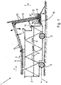
- FIG. 3 the side view of another embodiment of the mobile, semi-automatic picking aid according to the invention is shown in the lower picture, in the retracted and in the upper picture in the extended state.
- the picking a very essential part of the task, which is not achieved with the prior art and on the market picking aids, namely, that with one and the same machine picking both the lower part of the trees, as well -
- a second operation - can be done in the upper area.
- the horizontally arranged along its entire length collection tape is - in contrast to the embodiment of FIG. 1 - Connected via the supports firmly to the upper platform of the mobile picking device.
- the attachment between the supports and the upper platform is effected by not shown in detail, self-locking, provided with safety pins wedge connections, so that the collector can be solved after harvesting in a simple manner from the vehicle.
- the change in the working height is carried out by the scissors whose movement can be done by a hydraulic cylinder, not shown, or a chain hoist.
- the change in the lifting height is preferably 1.2 to 2 m.
- each two or three working platforms which preferably consist of gratings and are connected via holding elements to the upper platform.
- the platforms are near the ground, when harvesting in the upper area they are raised over the full stroke.
- the design is preferably such that two pickers can work on each platform, so that the collection tape is filled by up to eight pickers.
- the cover band already places itself on the collecting belt at the point in order to absolutely rule out that harvested fruits can fall out of the collecting belt when bent in the area.
- collecting tape can also be simple baffles according to when using bristle rows FIG. 7 Find use.
- the hinged base for the transport box can be with the guide device at the back of the picking carriage by a cylinder, not shown, or by a likewise not shown chain hoist - as in forklifts - up and down according to the arrows.
- This back and forth which is automatically controlled by not shown sensors and a computer program, has two tasks: once the up and down movement takes place synchronously with the adjustment of the working height by the scissors, on the other hand, the base bar at each lifting height and fixed scissors Slowly move down with increasing fill level.
- the base is lowered over the guides and in the vicinity of the ground, the folding in the in FIG. 1 described manner takes place.
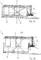
- FIG. 4 shows a cross-sectional view along the section line AA FIG. 3a ,
- a human picker 24 is shown placing apples 12 picked on the conveyor belt 6.
- the picking trolley 1 and the picking platforms 20 permanently connected thereto are in the lowered position.
- the rear of the picking trolley 1 arranged vertical piece of the conveyor belt 6 for conveying the guided over the conveyor belt 6 apples 12 in the collection box 11.
- the conveyor belt 6 has an upper run 25 and a lower run 26.
- the upper run 25 transports the fruit stored thereon, in particular the apples 12 in the conveying direction 7 and the lower run 26 represents the return of the conveyor belt 6.
- FIG. 4 is the schematic representation of a section through the mobile picking aid at the point AA in FIG. 3 ,
- the work platforms are lowered to pick the fruit in the lower part of the trees.
- the supports of the collecting tape are fastened at their lower ends on U-shaped supports, which exceed the description in the description FIG. 3 mentioned easily releasable wedge connections are connected to the upper plate.
- the belt of the collecting belt is connected in this particularly advantageous variant on both sides via terminals or connecting straps with the preferably elastic traction means, via the support rollers and the drive roller in FIG. 1 to run.
- This has the significant advantage that the collection and conveyor belt can be angled up and down in the filled state.
- a simple interchangeability is given.
- the belt of the collecting belt is provided with cylindrical nipples.
- FIG. 3 and FIG. 4 Describe the desire and the requirements to perform the picking in the upper and in the lower area in separate passes.
- FIG. 5 shows a further embodiment variant of the picking carriage 1, in which three in the conveying direction 7 relative to the vertical direction V at different heights positioned picking platforms 20 are arranged.
- the in the direction of travel related rear picking platforms 20 are again adjustable in height relative to the picking carriage 1. It is thus possible to pick fruit at three different heights at the same time as passing through the alley for harvesting.
- the structural design by means of the frame 2 and the use of the conveyor belt 6 allows a picking trolley 1 individually adapted to the needs of the picking area, the picking size and / or the harvest.
- the picking platform 20 on the image plane is equipped with a separate conveyor belt 6, which supplies a first vertical section of the actual conveyor belt 6.
- a cover 14 is provided, which according to Art a blind or shutter armor works and thus is adjustable in height.
- spaces 15 are then created in which the apples 12 can be introduced and conveyed upwards in the vertical direction V, wherein in turn a vertical discharge area is formed in the rear area, with a cover 14 around the harvested apples 12 in the Collection box to move 11, which is arranged on a road transport vehicle, not shown.
- the embodiment according to FIG. 5 By contrast, it is designed to pick at three different heights at the same time.
- the picking trolley can either be attached to a tractor or according to FIG. 1 be self-driving.
- the transport box is - according to the embodiment according to FIG. 3 - moved up and down at the rear end of the picking cart.
- the collection and conveyor belt is in the front of the picking carriage on the picking "down” designed and in the rear area on the picking "top".
- Sliding, limb-shaped cover plates, which are designed according to the principle of roller shutters, ensure that the apples in the steep areas can not fall out.
- FIG. 6 the embodiment of the invention is shown.
- the tractor 5 pulls a road transport carriage 27, on which the collecting boxes 11 are arranged in the direction of travel 23 in a row. If the first collecting box 11.1 is filled, then the tractor 5 can be moved forward relative to the picking trolley 1 in the direction of travel 23, and the outlet 17 of the conveyed apples 12 can be introduced into the second collecting box 11.2 related to the direction of travel 23. Is the last in the direction of travel 23 collection box 11.3 filled, so can the Pull out road transport car 27 with the tractor 5 completely and spend the apples 12 to a storage location. A new road transport car 27 with tractor 5 can in turn enter the picking carriage 1 and drive under the picking carriage 1, in which case the filling process begins again.
- the passageway 39 is then formed for entering or driving through the road transport car 27. Also, as shown here, the picking trolley 1 can be clamped to the road transport car 27. It is thus possible to pull the road transport car 27 by driving the tractor 5 in the direction of travel 23 and at the same time pull the picking trolley 1 so that fruit deposited on the conveyor belt 6 is filled directly by the picking trolley 1 in collecting crates 11 which are arranged on the road trolley 27 are.
- the forward movement of the tractor 5 can be briefly interrupted and the clamping or braking device released, so that the road transport carriage 27 makes a relative movement in the direction of travel 23 to the picking carriage 1 and then again the vertical conveyor, in particular the outlet 17 of the vertical conveyor, in the following on the direction of travel 23 second collection box 11.2 promotes the harvested fruit. Then, the forward drive of the tractor 5 and thus the harvesting process can be continued.
- this can drive out of the picking trolley 1 and an empty road transport car 27 and a road transport car 27 with empty collection boxes 11 can enter the transit lane 39 of the picking carriage 1.
- This embodiment is transferable to all other variants.
- FIG. 6 the embodiment of the invention is shown in a side view, which far exceeds all previously proposed solutions in procedural terms, because the picked fruit can be filled directly into the standing on the road transport trains transport crates.
- FIG. 2 shows the corresponding cross-section.
- FIG. 6 and FIG. 2 illustrated embodiment of the invention now makes it possible to raise by a particularly narrow construction of the side lattice girder of the picking trolley the collecting belt, so that the tractor can drive with the road transport train underneath.
- FIGS. 8a to c Good to see that each outboard rotating drawstring 29 is shown, extending from the drawstring 29 in the horizontal direction H and transverse to the conveying direction 7 coupling members 30, where the conveyor belt 6 or the cover band D are hung up.
- eyelets 31 are arranged, wherein the coupling members 30 are suspended or hooked into the eyelets 31.
- a lower web, on which the bristles of the brush strip 16 are fixed has a curvature, so that the conveyor belt 6 is bulged downward in terms of the vertical direction V downwards.
- the apples 12 deposited on the conveyor belt 6 thus all roll from the sides to a center and can then be removed in the conveying direction 7.
- the individual brush strips 16 are then arranged so that entrainment is given due to positive plant contact of each apple 12 by a brush strip 16.
- FIG. 8c illustrated individual webs or tiller arranged which enclose correspondingly form-fitting the apples 12 and take in the conveying direction 7.
- FIG. 8 The following is FIG. 8 further described.
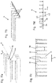
- FIG. 8 shows the top view of a particularly advantageous cover strip and the top view and the cross sections of three embodiments for the collection tape.
- the cover band consists of a net-like network of ribbons whose openings are sized so that even smaller fruits can not fall out.
- the upper plan view shows the embodiment variant with frustoconical elevations.
- the cross sections and the two lower plan views show nipples or rows of brushes which are fastened on the collecting belt.
- the rows of brushes are a particularly favorable solution.
- Both the collection and the cover band, the embodiment has been selected, run in the lateral traction over the support and the drive rollers and the collection or cover band is attached via eyelets and connecting straps on this traction means. As already mentioned, this is the best embodiment if the bands have to be angled both up and down.
- FIGS. 9a and b show a respective partial view of the conveyor belt 6.
- this is shown in plan view.
- the brush strips 16 and the collecting plate 32 are slowed down by gentle brushes 16 likewise arranged on the collecting plate 32 in such a way that they roll smoothly onto the collecting belt.
- the apples can thus be placed in several places on the collecting plate 32, wherein then based on the conveying direction 7, the brush strips 16, which finally passes the deposited apple 12 to get on the conveyor belt 6, in principle at an angle ⁇ less than 45 ° Direction 7 are oriented.
- the angle ⁇ is less than 45 °, in particular less than 40 °, and greater than 5 °.
- FIG. 9b shows a cross-sectional view through the conveyor belt 6. Good to see laterally rotating rollers 33 so that the upper strand 25 and the lower strand 26 are conveyed according to the conveying direction 7 via a laterally circulating drawstring 29. From this, H coupling members 30 are then arranged in the horizontal direction H, on which the conveyor belt 6 is suspended itself.
- the harvested apples 12 stored on the collecting plates 32 can thus roll gently and slowly onto the conveyor belt 6 and are transported away from the upper run 25, the lower run 26 leads the conveyor belt 6 back again.
- the collecting plates 32 are then arranged at an angle ⁇ to the horizontal direction H, so that in turn the apples 12 deposited on the collecting plate 32 roll on the conveyor belt 6 due to the gravitational force g and their own weight.
- FIG. 9 shows the top view and a cross section through a collection strip with bristle rows for the positioning of the apples to be conveyed, in which lateral inflow surfaces facilitate the picking "blind” depositing the apples.
- the laterally inclined inlet surfaces are also provided with bristle rows. In addition, they are padded so that it does not damage the apples even when "heavy" dropping or dropping.
- FIGS. 10a and b show a respective cross-sectional view through an upper part of the frame 2.
- the rollers 33 on which an outer circumferential drawstring 29 in the conveying direction 7 is circumferential. If the brush strip 16 is moved in the conveying direction 7, the brush plate itself can pass through the elastic deformation of the bristles themselves, the collecting plate 32 due to the flexibility of the brushes on the upper run 25.
- the collecting plates 32 can be adjusted at an angle ⁇ , so that they move a faster or more gentle rolling of the stored on the collecting plate 32 Good.
- appropriate brushes, as in FIG. 9 can be arranged on the collection plate 32 itself.
- side brushes 35 which prevent lateral drops of apples 12, not shown, transported on the conveyor belt 6.
- FIG. 10b It is shown that at the bottom 36 of the conveyor belt 6 a follower roller guide 37 is arranged so that the conveyor belt 6 is permanently lowered or bulged from a center, regardless of on the conveyor belt 6 stored Good. This makes it possible for the material to be conveyed on the conveyor belt 6 to roll due to the gravitational pull g into the center and to be transported away in the conveying direction 7. It is further shown that the conveyor belt 6 is formed at the lateral end regions or along its longitudinal sides 38 by folding double-layered or a webbing 52 is arranged on the underside 36. Also shown are laterally arranged, in cross-section C-shaped profiles 42. The profiles 42 are preferably made of light metal, in particular aluminum. In particular, these are canted aluminum profiles.
- the rollers 33 are then arranged for guiding and steering the drawstring 29.
- the profiles 42 are each coupled by a transverse web 44 or a plurality of transverse webs 44 arranged at a distance from one another in the conveying direction 7.
- the profiles 42 and the transverse webs 44 may be coupled together by riveting.
- a significant advantage of the invention is shown, according to which the conveyor belt 6 is formed offset inwardly on the horizontal direction H by the coupling members 30.
- the conveyor belt 6 is thus spaced from the rollers 33, in particular guide rollers.
- this as in FIG. 10b shown, have a downward curvature, so that stored fruit rolls due to its own weight always inward.
- the curvature can also be caused by a in FIG. 11a shown ridge 44 of the brush strips 16 done. This one is in FIG. 11a but straight, so without curvature, running.
- the web 44 is formed of either plastic or light metal and can then be preformed accordingly, so that it has a curvature. The coupled with the web 44 plastic tarpaulin is thus curved downward bulging.
- FIGS. 11a to d The brush strips 16 extend transversely to the conveying direction 7, the conveying direction 7 is shown in each case with arrows, wherein a lateral end along the longitudinal side 38 is folded accordingly and laterally the coupling members 30 in eyelets 31 are mounted. Further shown especially in FIG. 11d the thickness 34 of the plastic tarpaulin, which forms the conveyor belt 6 and the illustrated height 46, with which the brush strips 16 with respect to the top 45 of the conveyor belt 6 are formed projecting. The brush strips 16 are then each arranged at a distance 47 with respect to the conveying direction 7 to each other.
- the upper part of the frame 2 is shown, comprising the two opposite cross-sectionally C-shaped profiles 42. These may have a reinforcing profile 48, wherein the profiles 42 are particularly preferably made of thin light metal sheet, in particular aluminum sheet, by edges.
- the reinforcing profiles 48 may then be coupled to the profiles 42, for example by a riveting method.
- the collection plate 33 with brush strips 16 placed thereon are oriented in one direction only at an angle in order to supply the fruit deposited thereon to the conveyor belt (not shown).
- various collection plate holder 49 may be arranged so that depending on picking intensity of the fruit growing area optionally more collection plates 32 can be arranged and several pickers can be involved in the picking process.
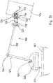
- FIG. 13 shows a side view of an inventive embodiment of a rotatably mounted picking 108 (buckling robot), which is rotatably mounted with its base plate 122 on the bracket 123, which in turn is mounted on the cover plate 107.
- this ensures full space mobility for the bars 127 and 128 so that they reach both the picking field assigned to the respective picking arm 108 by the sensors 132 and the computer 116a and also the area assigned to the collecting belt 6 can.
- the rod 128 is about 11 ⁇ 2 times as long as the rod 127.
- the gripping device 109 is arranged in such a manner that in the bearing 129 a rotational movement and about the bolt 130 a pivoting movement is possible.
- the gripping device 109 targeted to the selected via the sensors from the computer and the electronic control devices to be harvested fruit in the area to can be moved.
- the gripping device 109 After enclosing the fruit by the fingers 131 performs the gripping device 109 - controlled by the computer - specified for each fruit movement, so that the "breaking point", ie in most cases, the weak point on the stem, breaks off at the desired location or is severed.
- the moving and rotating speeds of the rods 127 and 128 must be very high. Therefore, the rods 127, 128 and the gripping device 109 in lightweight construction, preferably made of plastic or high-strength materials designed to achieve high accelerations and equally large delays by the actuators and transmission elements, not shown in detail.
- the movement speeds of the gripping device 109 are more than 1 m / s.
- a distance sensor 132 which slows down when approaching the selected from the controller fruit to be picked about 10 to 20 cm before touching the high approach speed and ensures a slow approach over the last distance.
- sensors 133 preferably small cameras, can be arranged which emit a status message to the computer when enclosing the fruit or send an image, which are compared with a desired value or corresponding image for quality control in the computer. This can be achieved at lower quality, that the picked fruit not the Sammelband 6, but another collecting device, eg. B. for fruit to be fed, is supplied.
- the spread apart when approaching the fruit to be picked fingers 131 of the gripping device 109 close and lie gently to the fruit to be picked when the distance sensor 132 reports the contact.
- the approaching movement is terminated at the same time and initiated for the actual picking process, stored in the computer movement sequence of the gripping device 109 and the rods 127 and 128 initiated.
- the fingers 131 are coated on their inner side with pads 134.
- the fingers 131 can also be designed so that they automatically attach to the fruit to be harvested after a first contact on the lower part of the fingers 131 due to their special construction.
- the picking arm 108 has two articulated sections 169 and 170, also referred to above as the arm section, and a rotatably mounted base plate 171.
- Compressed air cylinders 172 and 173 ensure fast movements.
- preferably 6 plastic tubes 174 are arranged on a circle.
- Distances ensure stabilization plates 175 for a high dimensional stability.
- a suction device 176 At the free end of the picking arm is a suction device 176, in which just before touching the fruit to be picked by a pump, not shown, a negative pressure is generated, which leads to a firm suction and a stable adhesion. To store the picked fruit on the collecting belt 6, the negative pressure is stopped. Furthermore, a section along the line AA is shown.
Landscapes
- Life Sciences & Earth Sciences (AREA)
- Environmental Sciences (AREA)
- Engineering & Computer Science (AREA)
- Robotics (AREA)
- Harvesting Machines For Specific Crops (AREA)
Priority Applications (1)
| Application Number | Priority Date | Filing Date | Title |
|---|---|---|---|
| PL16756566T PL3324728T3 (pl) | 2015-07-17 | 2016-07-15 | Układ pojazdu do zrywania w celu mechanizacji zbiorów owoców z pojazdem do zrywania mającym uliczkę do przejazdu dołem |
Applications Claiming Priority (3)
| Application Number | Priority Date | Filing Date | Title |
|---|---|---|---|
| DE102015111682.0A DE102015111682A1 (de) | 2015-07-17 | 2015-07-17 | Vollautomatisches Pflücksystem sowie Verfahren zum Betreiben des Pflücksystems |
| DE102015111665.0A DE102015111665A1 (de) | 2015-07-17 | 2015-07-17 | Pflückwagen zur Mechanisierung der Obsternte mit Sammelband und Abrolltisch |
| PCT/DE2016/000275 WO2017012604A1 (de) | 2015-07-17 | 2016-07-15 | Pflückwagensystem zur mechanisierung der obsternte mit einem eine unterfahrgasse aufweisenden pflückwagen |
Publications (2)
| Publication Number | Publication Date |
|---|---|
| EP3324728A1 EP3324728A1 (de) | 2018-05-30 |
| EP3324728B1 true EP3324728B1 (de) | 2019-05-22 |
Family
ID=56799153
Family Applications (1)
| Application Number | Title | Priority Date | Filing Date |
|---|---|---|---|
| EP16756566.2A Not-in-force EP3324728B1 (de) | 2015-07-17 | 2016-07-15 | Pflückwagensystem zur mechanisierung der obsternte mit einem eine unterfahrgasse aufweisenden pflückwagen |
Country Status (3)
| Country | Link |
|---|---|
| EP (1) | EP3324728B1 (pl) |
| PL (1) | PL3324728T3 (pl) |
| WO (1) | WO2017012604A1 (pl) |
Cited By (1)
| Publication number | Priority date | Publication date | Assignee | Title |
|---|---|---|---|---|
| US11910753B2 (en) | 2016-12-15 | 2024-02-27 | Richard Arnold | Harvest accessory for a tractor mounted work platform |
Families Citing this family (11)
| Publication number | Priority date | Publication date | Assignee | Title |
|---|---|---|---|---|
| WO2018152555A1 (en) * | 2017-02-14 | 2018-08-23 | Frederik Brand | Harvester |
| CN108476732B (zh) * | 2018-05-25 | 2023-08-04 | 辽宁工业大学 | 基于方向盘操控的类球形水果采摘装置 |
| CN108848898B (zh) * | 2018-07-02 | 2023-07-21 | 浙江工业大学 | 基于半自动化草莓柔性采摘的匍匐茎切断机构 |
| CN109156166A (zh) * | 2018-10-26 | 2019-01-08 | 安徽理工大学 | 一种自动草莓采摘装置 |
| IL273316B (en) * | 2020-03-15 | 2021-02-28 | Tevel Aerobotics Tech Ltd | Device and method for picking fruit |
| CN111567214B (zh) * | 2020-06-19 | 2024-10-15 | 山东农业大学 | 一种全自动番茄自动采摘运输一体化机器人及使用方法 |
| CN112586183A (zh) * | 2020-12-15 | 2021-04-02 | 高飞 | 一种利用限位的侧柏枝加工装置 |
| CN113330905B (zh) * | 2021-06-25 | 2022-05-31 | 济宁市农业科学研究院 | 一种大豆采摘系统及方法 |
| CN118120472A (zh) * | 2024-04-02 | 2024-06-04 | 青岛耕云科技有限公司 | 一种用于玻璃温室数据采集的农业采摘车 |
| CN119732259A (zh) * | 2024-12-30 | 2025-04-01 | 上海大学 | 一种成熟果实采摘方法 |
| CN120304165B (zh) * | 2025-04-21 | 2026-04-21 | 青岛农业大学 | 一种采茶机器人 |
Family Cites Families (3)
| Publication number | Priority date | Publication date | Assignee | Title |
|---|---|---|---|---|
| NL7210766A (pl) * | 1972-08-07 | 1974-02-11 | ||
| DE202011107841U1 (de) * | 2011-11-10 | 2012-01-19 | Daniel Gruber | Obstverleseband |
| US9723787B2 (en) * | 2013-12-23 | 2017-08-08 | Huron Fruit Systems, Inc. | Fruit harvester platform |
-
2016
- 2016-07-15 PL PL16756566T patent/PL3324728T3/pl unknown
- 2016-07-15 WO PCT/DE2016/000275 patent/WO2017012604A1/de not_active Ceased
- 2016-07-15 EP EP16756566.2A patent/EP3324728B1/de not_active Not-in-force
Non-Patent Citations (1)
| Title |
|---|
| None * |
Cited By (1)
| Publication number | Priority date | Publication date | Assignee | Title |
|---|---|---|---|---|
| US11910753B2 (en) | 2016-12-15 | 2024-02-27 | Richard Arnold | Harvest accessory for a tractor mounted work platform |
Also Published As
| Publication number | Publication date |
|---|---|
| PL3324728T3 (pl) | 2020-01-31 |
| EP3324728A1 (de) | 2018-05-30 |
| WO2017012604A1 (de) | 2017-01-26 |
Similar Documents
| Publication | Publication Date | Title |
|---|---|---|
| EP3324728A1 (de) | Pflückwagensystem zur mechanisierung der obsternte mit einem eine unterfahrgasse aufweisenden pflückwagen | |
| DE102015111665A1 (de) | Pflückwagen zur Mechanisierung der Obsternte mit Sammelband und Abrolltisch | |
| DE102015111682A1 (de) | Vollautomatisches Pflücksystem sowie Verfahren zum Betreiben des Pflücksystems | |
| EP2067399B1 (de) | Anordnung zur Verstellung der Position einer Aufnehmertrommel und eines Niederhalters einer landwirtschaftlichen Erntemaschine | |
| DE102017100610A1 (de) | Pflückwagen mit Gasse | |
| DE102017100619A1 (de) | Pflückwagen | |
| DE102015111650A1 (de) | Erntesystem mit automatischem Transportkistenwechsel | |
| DE60310619T2 (de) | Selbstfahrendes Fahrzeug zum Handhaben und Transportieren von Kisten | |
| EP3440922B1 (de) | Ballentransportwagen | |
| DE2115862A1 (de) | Ballenladewagen | |
| DE2018156C3 (de) | Mit einer Schlauchtrommel, sowie einer verfahrbaren Laufkatze versehene Vorrichtung zum Bearbeiten landwirtschaftlicher Reihenkulturen | |
| EP4305952A1 (de) | Landwirtschaftlicher ladewagen | |
| DE2533311C2 (de) | Selbstfahrende Hopfenpflückmaschine sowie Erntevorrichtung hierfür | |
| DE102019101857B4 (de) | Fahrzeug zum Anheben, Transportieren und Absenken von Ladungsträgern | |
| WO2016118986A1 (de) | Vorrichtung zum laden und zum transport von rundballen | |
| DE2316616C2 (de) | Ballenladewagen | |
| DE2553438C2 (de) | Vorrichtung zur Handhabung von Rundballen | |
| DE2553437A1 (de) | Vorrichtung zur handhabung von heu- oder futterballen | |
| DE2454581C3 (de) | Fahrbarer Kettenhöhenförderer für Preßballen | |
| DE2115861A1 (de) | Ballenladewagen | |
| DE2413460C3 (de) | Transportkarrensystem | |
| DE4422311A1 (de) | Verfahren und Preßballensammelgerät zum Abtransport von quaderförmigen Preßballen aus gepreßtem Erntegut oder Ernterückständen | |
| DE3726700C1 (en) | Loading system for pressed bales mountable on a tractor | |
| EP4442106A1 (de) | Ballensammelwagen zum transportieren eines ballens, arbeitszug umfassend eine rundballenpresse und einen solchen ballensammelwagen, sowie verfahren zum entladen von ballen aus einer rundballenpresse eines solchen arbeitszuges | |
| DE4306944C1 (de) | Einrichtung zum Überdecken von Schwaden oder anderen Flächen auf Acker- und Grünland |
Legal Events
| Date | Code | Title | Description |
|---|---|---|---|
| STAA | Information on the status of an ep patent application or granted ep patent |
Free format text: STATUS: THE INTERNATIONAL PUBLICATION HAS BEEN MADE |
|
| PUAI | Public reference made under article 153(3) epc to a published international application that has entered the european phase |
Free format text: ORIGINAL CODE: 0009012 |
|
| STAA | Information on the status of an ep patent application or granted ep patent |
Free format text: STATUS: REQUEST FOR EXAMINATION WAS MADE |
|
| 17P | Request for examination filed |
Effective date: 20171018 |
|
| AK | Designated contracting states |
Kind code of ref document: A1 Designated state(s): AL AT BE BG CH CY CZ DE DK EE ES FI FR GB GR HR HU IE IS IT LI LT LU LV MC MK MT NL NO PL PT RO RS SE SI SK SM TR |
|
| AX | Request for extension of the european patent |
Extension state: BA ME |
|
| DAV | Request for validation of the european patent (deleted) | ||
| DAX | Request for extension of the european patent (deleted) | ||
| GRAJ | Information related to disapproval of communication of intention to grant by the applicant or resumption of examination proceedings by the epo deleted |
Free format text: ORIGINAL CODE: EPIDOSDIGR1 |
|
| STAA | Information on the status of an ep patent application or granted ep patent |
Free format text: STATUS: GRANT OF PATENT IS INTENDED |
|
| GRAP | Despatch of communication of intention to grant a patent |
Free format text: ORIGINAL CODE: EPIDOSNIGR1 |
|
| INTG | Intention to grant announced |
Effective date: 20181214 |
|
| GRAS | Grant fee paid |
Free format text: ORIGINAL CODE: EPIDOSNIGR3 |
|
| GRAA | (expected) grant |
Free format text: ORIGINAL CODE: 0009210 |
|
| STAA | Information on the status of an ep patent application or granted ep patent |
Free format text: STATUS: THE PATENT HAS BEEN GRANTED |
|
| AK | Designated contracting states |
Kind code of ref document: B1 Designated state(s): AL AT BE BG CH CY CZ DE DK EE ES FI FR GB GR HR HU IE IS IT LI LT LU LV MC MK MT NL NO PL PT RO RS SE SI SK SM TR |
|
| RAP1 | Party data changed (applicant data changed or rights of an application transferred) |
Owner name: SPIES, KLAUS |
|
| REG | Reference to a national code |
Ref country code: GB Ref legal event code: FG4D Free format text: NOT ENGLISH |
|
| RIN1 | Information on inventor provided before grant (corrected) |
Inventor name: SPIES, KLAUS |
|
| REG | Reference to a national code |
Ref country code: CH Ref legal event code: EP |
|
| REG | Reference to a national code |
Ref country code: IE Ref legal event code: FG4D Free format text: LANGUAGE OF EP DOCUMENT: GERMAN |
|
| REG | Reference to a national code |
Ref country code: DE Ref legal event code: R096 Ref document number: 502016004820 Country of ref document: DE |
|
| REG | Reference to a national code |
Ref country code: AT Ref legal event code: REF Ref document number: 1134939 Country of ref document: AT Kind code of ref document: T Effective date: 20190615 |
|
| REG | Reference to a national code |
Ref country code: NL Ref legal event code: MP Effective date: 20190522 |
|
| REG | Reference to a national code |
Ref country code: LT Ref legal event code: MG4D |
|
| PG25 | Lapsed in a contracting state [announced via postgrant information from national office to epo] |
Ref country code: LT Free format text: LAPSE BECAUSE OF FAILURE TO SUBMIT A TRANSLATION OF THE DESCRIPTION OR TO PAY THE FEE WITHIN THE PRESCRIBED TIME-LIMIT Effective date: 20190522 Ref country code: HR Free format text: LAPSE BECAUSE OF FAILURE TO SUBMIT A TRANSLATION OF THE DESCRIPTION OR TO PAY THE FEE WITHIN THE PRESCRIBED TIME-LIMIT Effective date: 20190522 Ref country code: FI Free format text: LAPSE BECAUSE OF FAILURE TO SUBMIT A TRANSLATION OF THE DESCRIPTION OR TO PAY THE FEE WITHIN THE PRESCRIBED TIME-LIMIT Effective date: 20190522 Ref country code: AL Free format text: LAPSE BECAUSE OF FAILURE TO SUBMIT A TRANSLATION OF THE DESCRIPTION OR TO PAY THE FEE WITHIN THE PRESCRIBED TIME-LIMIT Effective date: 20190522 Ref country code: SE Free format text: LAPSE BECAUSE OF FAILURE TO SUBMIT A TRANSLATION OF THE DESCRIPTION OR TO PAY THE FEE WITHIN THE PRESCRIBED TIME-LIMIT Effective date: 20190522 Ref country code: PT Free format text: LAPSE BECAUSE OF FAILURE TO SUBMIT A TRANSLATION OF THE DESCRIPTION OR TO PAY THE FEE WITHIN THE PRESCRIBED TIME-LIMIT Effective date: 20190922 Ref country code: NO Free format text: LAPSE BECAUSE OF FAILURE TO SUBMIT A TRANSLATION OF THE DESCRIPTION OR TO PAY THE FEE WITHIN THE PRESCRIBED TIME-LIMIT Effective date: 20190822 Ref country code: ES Free format text: LAPSE BECAUSE OF FAILURE TO SUBMIT A TRANSLATION OF THE DESCRIPTION OR TO PAY THE FEE WITHIN THE PRESCRIBED TIME-LIMIT Effective date: 20190522 Ref country code: NL Free format text: LAPSE BECAUSE OF FAILURE TO SUBMIT A TRANSLATION OF THE DESCRIPTION OR TO PAY THE FEE WITHIN THE PRESCRIBED TIME-LIMIT Effective date: 20190522 |
|
| PG25 | Lapsed in a contracting state [announced via postgrant information from national office to epo] |
Ref country code: RS Free format text: LAPSE BECAUSE OF FAILURE TO SUBMIT A TRANSLATION OF THE DESCRIPTION OR TO PAY THE FEE WITHIN THE PRESCRIBED TIME-LIMIT Effective date: 20190522 Ref country code: BG Free format text: LAPSE BECAUSE OF FAILURE TO SUBMIT A TRANSLATION OF THE DESCRIPTION OR TO PAY THE FEE WITHIN THE PRESCRIBED TIME-LIMIT Effective date: 20190822 Ref country code: LV Free format text: LAPSE BECAUSE OF FAILURE TO SUBMIT A TRANSLATION OF THE DESCRIPTION OR TO PAY THE FEE WITHIN THE PRESCRIBED TIME-LIMIT Effective date: 20190522 Ref country code: GR Free format text: LAPSE BECAUSE OF FAILURE TO SUBMIT A TRANSLATION OF THE DESCRIPTION OR TO PAY THE FEE WITHIN THE PRESCRIBED TIME-LIMIT Effective date: 20190823 |
|
| PG25 | Lapsed in a contracting state [announced via postgrant information from national office to epo] |
Ref country code: SK Free format text: LAPSE BECAUSE OF FAILURE TO SUBMIT A TRANSLATION OF THE DESCRIPTION OR TO PAY THE FEE WITHIN THE PRESCRIBED TIME-LIMIT Effective date: 20190522 Ref country code: EE Free format text: LAPSE BECAUSE OF FAILURE TO SUBMIT A TRANSLATION OF THE DESCRIPTION OR TO PAY THE FEE WITHIN THE PRESCRIBED TIME-LIMIT Effective date: 20190522 Ref country code: DK Free format text: LAPSE BECAUSE OF FAILURE TO SUBMIT A TRANSLATION OF THE DESCRIPTION OR TO PAY THE FEE WITHIN THE PRESCRIBED TIME-LIMIT Effective date: 20190522 Ref country code: CZ Free format text: LAPSE BECAUSE OF FAILURE TO SUBMIT A TRANSLATION OF THE DESCRIPTION OR TO PAY THE FEE WITHIN THE PRESCRIBED TIME-LIMIT Effective date: 20190522 Ref country code: RO Free format text: LAPSE BECAUSE OF FAILURE TO SUBMIT A TRANSLATION OF THE DESCRIPTION OR TO PAY THE FEE WITHIN THE PRESCRIBED TIME-LIMIT Effective date: 20190522 |
|
| REG | Reference to a national code |
Ref country code: DE Ref legal event code: R097 Ref document number: 502016004820 Country of ref document: DE |
|
| PG25 | Lapsed in a contracting state [announced via postgrant information from national office to epo] |
Ref country code: SM Free format text: LAPSE BECAUSE OF FAILURE TO SUBMIT A TRANSLATION OF THE DESCRIPTION OR TO PAY THE FEE WITHIN THE PRESCRIBED TIME-LIMIT Effective date: 20190522 Ref country code: MC Free format text: LAPSE BECAUSE OF FAILURE TO SUBMIT A TRANSLATION OF THE DESCRIPTION OR TO PAY THE FEE WITHIN THE PRESCRIBED TIME-LIMIT Effective date: 20190522 |
|
| REG | Reference to a national code |
Ref country code: CH Ref legal event code: PL |
|
| PLBE | No opposition filed within time limit |
Free format text: ORIGINAL CODE: 0009261 |
|
| STAA | Information on the status of an ep patent application or granted ep patent |
Free format text: STATUS: NO OPPOSITION FILED WITHIN TIME LIMIT |
|
| PG25 | Lapsed in a contracting state [announced via postgrant information from national office to epo] |
Ref country code: TR Free format text: LAPSE BECAUSE OF FAILURE TO SUBMIT A TRANSLATION OF THE DESCRIPTION OR TO PAY THE FEE WITHIN THE PRESCRIBED TIME-LIMIT Effective date: 20190522 |
|
| REG | Reference to a national code |
Ref country code: BE Ref legal event code: MM Effective date: 20190731 |
|
| 26N | No opposition filed |
Effective date: 20200225 |
|
| PG25 | Lapsed in a contracting state [announced via postgrant information from national office to epo] |
Ref country code: LU Free format text: LAPSE BECAUSE OF NON-PAYMENT OF DUE FEES Effective date: 20190715 Ref country code: CH Free format text: LAPSE BECAUSE OF NON-PAYMENT OF DUE FEES Effective date: 20190731 Ref country code: LI Free format text: LAPSE BECAUSE OF NON-PAYMENT OF DUE FEES Effective date: 20190731 Ref country code: SI Free format text: LAPSE BECAUSE OF FAILURE TO SUBMIT A TRANSLATION OF THE DESCRIPTION OR TO PAY THE FEE WITHIN THE PRESCRIBED TIME-LIMIT Effective date: 20190522 Ref country code: BE Free format text: LAPSE BECAUSE OF NON-PAYMENT OF DUE FEES Effective date: 20190731 |
|
| PG25 | Lapsed in a contracting state [announced via postgrant information from national office to epo] |
Ref country code: FR Free format text: LAPSE BECAUSE OF NON-PAYMENT OF DUE FEES Effective date: 20190722 |
|
| PG25 | Lapsed in a contracting state [announced via postgrant information from national office to epo] |
Ref country code: IE Free format text: LAPSE BECAUSE OF NON-PAYMENT OF DUE FEES Effective date: 20190715 |
|
| PGFP | Annual fee paid to national office [announced via postgrant information from national office to epo] |
Ref country code: PL Payment date: 20200706 Year of fee payment: 5 Ref country code: IT Payment date: 20200724 Year of fee payment: 5 |
|
| GBPC | Gb: european patent ceased through non-payment of renewal fee |
Effective date: 20200715 |
|
| PG25 | Lapsed in a contracting state [announced via postgrant information from national office to epo] |
Ref country code: GB Free format text: LAPSE BECAUSE OF NON-PAYMENT OF DUE FEES Effective date: 20200715 |
|
| PG25 | Lapsed in a contracting state [announced via postgrant information from national office to epo] |
Ref country code: CY Free format text: LAPSE BECAUSE OF FAILURE TO SUBMIT A TRANSLATION OF THE DESCRIPTION OR TO PAY THE FEE WITHIN THE PRESCRIBED TIME-LIMIT Effective date: 20190522 |
|
| PG25 | Lapsed in a contracting state [announced via postgrant information from national office to epo] |
Ref country code: IS Free format text: LAPSE BECAUSE OF FAILURE TO SUBMIT A TRANSLATION OF THE DESCRIPTION OR TO PAY THE FEE WITHIN THE PRESCRIBED TIME-LIMIT Effective date: 20190922 |
|
| PG25 | Lapsed in a contracting state [announced via postgrant information from national office to epo] |
Ref country code: HU Free format text: LAPSE BECAUSE OF FAILURE TO SUBMIT A TRANSLATION OF THE DESCRIPTION OR TO PAY THE FEE WITHIN THE PRESCRIBED TIME-LIMIT; INVALID AB INITIO Effective date: 20160715 Ref country code: MT Free format text: LAPSE BECAUSE OF FAILURE TO SUBMIT A TRANSLATION OF THE DESCRIPTION OR TO PAY THE FEE WITHIN THE PRESCRIBED TIME-LIMIT Effective date: 20190522 |
|
| PGFP | Annual fee paid to national office [announced via postgrant information from national office to epo] |
Ref country code: DE Payment date: 20210729 Year of fee payment: 6 |
|
| PG25 | Lapsed in a contracting state [announced via postgrant information from national office to epo] |
Ref country code: MK Free format text: LAPSE BECAUSE OF FAILURE TO SUBMIT A TRANSLATION OF THE DESCRIPTION OR TO PAY THE FEE WITHIN THE PRESCRIBED TIME-LIMIT Effective date: 20190522 |
|
| PG25 | Lapsed in a contracting state [announced via postgrant information from national office to epo] |
Ref country code: IT Free format text: LAPSE BECAUSE OF NON-PAYMENT OF DUE FEES Effective date: 20210715 |
|
| REG | Reference to a national code |
Ref country code: AT Ref legal event code: MM01 Ref document number: 1134939 Country of ref document: AT Kind code of ref document: T Effective date: 20210715 |
|
| PG25 | Lapsed in a contracting state [announced via postgrant information from national office to epo] |
Ref country code: AT Free format text: LAPSE BECAUSE OF NON-PAYMENT OF DUE FEES Effective date: 20210715 |
|
| REG | Reference to a national code |
Ref country code: DE Ref legal event code: R119 Ref document number: 502016004820 Country of ref document: DE |
|
| PG25 | Lapsed in a contracting state [announced via postgrant information from national office to epo] |
Ref country code: PL Free format text: LAPSE BECAUSE OF NON-PAYMENT OF DUE FEES Effective date: 20210715 Ref country code: DE Free format text: LAPSE BECAUSE OF NON-PAYMENT OF DUE FEES Effective date: 20230201 |