EP3324125B1 - Gargerät mit türschloss - Google Patents
Gargerät mit türschloss Download PDFInfo
- Publication number
- EP3324125B1 EP3324125B1 EP17196051.1A EP17196051A EP3324125B1 EP 3324125 B1 EP3324125 B1 EP 3324125B1 EP 17196051 A EP17196051 A EP 17196051A EP 3324125 B1 EP3324125 B1 EP 3324125B1
- Authority
- EP
- European Patent Office
- Prior art keywords
- door
- appliance
- state
- lock
- cooking
- Prior art date
- Legal status (The legal status is an assumption and is not a legal conclusion. Google has not performed a legal analysis and makes no representation as to the accuracy of the status listed.)
- Active
Links
Images



Classifications
-
- F—MECHANICAL ENGINEERING; LIGHTING; HEATING; WEAPONS; BLASTING
- F24—HEATING; RANGES; VENTILATING
- F24C—DOMESTIC STOVES OR RANGES ; DETAILS OF DOMESTIC STOVES OR RANGES, OF GENERAL APPLICATION
- F24C15/00—Details
- F24C15/02—Doors specially adapted for stoves or ranges
- F24C15/022—Latches
Definitions
- the present invention relates to a cooking appliance and in particular to a pyrolysis-capable oven according to the preamble of claim 1.
- Such a cooking device is from the DE 100 27 774 A1 known.
- Known closure system for a furnace there are a pair of identical closures, one of which is arranged in the upper region and another in the lower region of a door pivotable about a vertical axis.
- Each lock has a lever that extends beyond the front of the door and both levers are connected to each other by a rod-shaped handle.
- the levers are movable between a closed position, a released position and a fully open position. In the released position, the door is opened in columns.
- the DE 100 27 774 A1 shows an oven with a locking piston on the door, which engages in a lock box on the housing. So that the door can be opened in columns, one of the locking elements is movably attached to the housing or to the door. The door then remains in this position until an unlocking takes place, which enables a complete opening from the gap-open position.
- One from the EP 2 845 532 A1 Known household appliance comprises a device body and a treatment room with a loading opening which can be closed by a door.
- a push element can move the door in the pressing direction, so that a door lock is unlocked.
- An opening of the door can then be caused by reversing the direction of movement of the push element, by spring force or a combination thereof.
- a cooking device is designed in particular as a pyrolysis-capable oven or comprises one.
- the cooking appliance comprises at least two components, one component being an appliance housing and one component being an appliance door.
- the appliance door is arranged to be movable relative to the appliance housing. This means that the appliance door can be pivoted on the appliance housing, alternatively it can be moved away from the housing with a so-called baking cart.
- a door lock is used to lock the appliance door. In a first state, the appliance door is in a closed position and the door lock is in an engagement position in engagement with the appliance door. In a second state, the appliance door is in an at least gap-open position and the door lock in the engagement position is in engagement with the appliance door. In a third state, the door lock is in a release position and releases the appliance door.
- At least one cooking program is stored or programmable, in which the gap-open position can be activated during the program sequence and / or towards the end of the program.
- the appliance door is preloaded with a spring device in the opening direction. This means that in the third state the door automatically opens at least in gaps or more.
- the appliance door is opened by the spring force of the spring device.
- the appliance door can be transferred from the closed position to the gap-open position.
- the door it is also possible for the door to be opened further than in columns.
- the device door can be opened almost completely or completely. Such an embodiment is useful, for example, for handle-less variants of the appliance door or the cooking appliance.
- the cooking device according to the invention offers many advantages.
- a significant advantage of the cooking device according to the invention is that a multitude of functions are made available with the door lock.
- the cooking appliance and in particular the appliance door, the lock and the appliance housing can be converted into different states.
- the individual states are defined by the positions of the individual parts and components. In a first state, the appliance door is in a closed position and the door lock is in an engagement position with the appliance door. This means that the appliance door is held by the door lock. In a second state, the appliance door is in an open position at least in columns and in particular in columns, while the door lock is (still) in engagement with the appliance door. This means that the appliance door is held by the door lock even in this gap-wise opening position.
- the door lock In a third state, the door lock is in a release position and releases the appliance door. Then the appliance door can open automatically.
- the door lock comprises a lock housing mounted on a first of the components and a lock latch on the second component.
- the door lock preferably comprises a locking device which can be extended relative to the lock housing and which is extended in particular in the second state.
- the locking device is preferably retracted (partially or completely) in the first state. This means that during the transfer from the first state to the second state, the locking device is transferred from the (further) retracted position to the (further) extended position.
- the door lock can remain in the engaged position and be in engagement with the appliance door.
- a drive means is provided in order to convert the first state into the second state and vice versa.
- the appliance door is transferred from the closed position to the gap-open position and / or from the gap-open position (back again) to the closed position while the door lock is (preferably continuously) in the engaged position.
- a drive means for the controlled transfer into the first state and the second state and / or back offers considerable advantages, since it enables the device door to be specifically opened in the program sequence. Controlled closing of the appliance door can also be carried out.
- a transition from the first state to the second state by means of the drive means takes place more slowly than an opening of the appliance door by the spring force of the spring device in the third state.
- the first state is preferably converted into the second state with the drive means within 15 to 90 seconds and preferably within 25 to 60 seconds.
- the appliance door is transferred from the closed position into the at least gap-open position within less than 15 seconds and in particular within less than 10 seconds by means of the spring force of the spring device. Opening is also possible and preferred within 5 seconds or 4 seconds.
- the appliance door can be opened by means of the spring force of the spring device, the appliance door is preferably designed without a handle. Then, by pressing a button or under program control, the door can be opened at least in columns or completely.
- the appliance door can be transferred from the second state by applying tensile or compressive force into the closed position or into a further open position.
- a further open position can be, for example, the (almost) fully open position.
- the appliance door can be transferred manually from the gap-open position into the fully open position or into the closed position by applying tensile or compressive force, this enables flexible manual intervention by the user. If, for example, the user determines that the food to be cooked is ready, he can open the appliance door completely to remove the food to be cooked.
- a gap-wise opening of the appliance door is controlled by the program preferably when a so-called rapid cooling is to be carried out, in which the heat present in the cooking space is to be dissipated as quickly as possible in order to prevent further cooking of the food. It is possible that the temperature in the cooking space is reduced to such a level that the food is at the right temperature for consumption.
- the user can simply grasp the appliance door and open it further without pressing buttons or sensors in order to remove the food to be cooked. If the user then determines that he would rather leave the food to be cooked in the cooking space, he can, if necessary, bring the appliance door back into the gap-open position and lock it with the locking device.
- a button or the like is preferably provided (button, sensor, etc.), and when the button is pressed, the appliance door is moved into the gap-open position and / or a further open position (automatically).
- a fourth state is provided in which the door lock is locked and the appliance door is closed.
- a fourth state is particularly advantageous if the cooking device is provided for a pyrolysis function and a pyrolysis program is stored.
- the fourth state is preferably activated. The appliance door is closed (active) and the door lock (active) is locked, so that in this state it is no longer possible for the user to open the door manually.
- Figures 1 to 3 show different states 41-43 of the cooking appliance 1 or the door lock 3 and the appliance door 5.
- Figure 1 shows a strong schematic perspective view of the cooking device 1, wherein the cooking device 1 has an appliance housing 4 and an appliance door 5.
- the appliance door 5 is received on the appliance housing 4 via hinges 55 so that it can pivot about a pivot axis 57 oriented horizontally here. Alternatively, it can be moved away from the device housing 4 together with a so-called baking cart (not shown).
- the appliance cooling is provided above the cooking space.
- the door lock 3 is fastened, with the lock housing 6 being fastened to the device housing 4 and the lock latch 2 being formed on the device door 5.
- Figure 1 shows the cooking appliance in the state 41, the appliance door 5 being in the closed position 50.
- the door lock 3 or the locking device 7 (compare Figure 4 ) of the door lock 3 is in Figure 1 in the closed position 70.
- the appliance door 5 can be preloaded by spring devices 54, for example on the hinges 55, into the open or the closed position 50 of the appliance door 5. In any case, the appliance door 5 is in the state 41 according to Figure 1 held by the device lock 3.
- the appliance door 5 can be opened automatically by pressing the button 46.
- FIG 2 shows a highly schematic side view of the cooking appliance 1 Figure 1 , wherein the cooking appliance is in state 42.
- the door lock 3 or the locking hook 8 is in the engagement position 80 and is in engagement with the appliance door 5.
- the appliance door 5 is shown in the illustration Figure 2 opened in the opening direction 53 in columns.
- the locking hook 8 or the door lock 3 are in engagement with the appliance door 5, so that the appliance door 5 is fixed in the gap 51 open position.
- the locking device 7 is in the extended position 71. The retraction and extension of the locking device 7 is driven in particular by a drive means 11.
- the locking hook 8 is transferred into the release position 81 and if the appliance door is preloaded in the opening direction 53, the appliance door 5 opens automatically after the transfer of the locking hook into the release position 81, so that a state 43 results, as shown in FIG Figure 3 is shown.
- the appliance door is then in a further open position 52.
- This further opened position 52 can be the fully open position of the appliance door.
- Figure 4 shows a perspective top view of a door lock 3, which comprises a lock housing 6, which is intended for this, attached to the device housing 4 to become.
- the lock latch 2 is provided on the appliance door, of which only the door cover strip 58 can be seen here.
- the hook housing 9 of the door lock 3 is immersed in the lock latch 2.
- the locking hook 8 is pivoted laterally out of the hook housing 9 and is in the engagement position 80, in which the appliance door 5 is held in the given position by the door lock 3.
- Switches 24, 25 and 26 are provided for recognizing different positions.
- a motor 12, which acts on the locking device 7, is provided to control various positions and states.
- FIG Figure 5 shows an alternative embodiment in which the door lock 3 is prepared for the use of a handle-less door.
- an active actuating element 20 which can be designed, for example, as a synchronous motor and is used to actively release the appliance door.
- the drive means 20 can ensure that the appliance door 5 is opened completely and not just in columns.
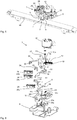
- Figure 6 shows an exploded view of the door lock 3 Figure 4 ,
- the lowest component shown is the lock housing 6, which is attached here to the device housing 4.
- the hook housing 9 is received, which consists of the lower part 18 of the hook housing and the upper part 19 of the hook housing.
- a spring receptacle 18a can be seen on the hook housing lower part 18, on which a preloading unit 82 is arranged in the assembled state in order to preload the locking hook 8 into the engagement position 80 (cf. Figure 9 ).
- the locking hook 8 is pivotally received in the hook housing 9.
- the locking hook 8 is pivotally mounted about a pivot axis 85 of the lower part 18 and has an engagement section 83 at one end and a bracket 84 at the other end.
- the preloading unit 82 is located between the bracket 84 and the spring mount 18a.
- three different switches 24, 25 and 26 are provided, each of which has one of the buttons 24a, 25a and 26a.
- the switch 24 and its button 24a is activated outside the locked and outside the extended position.
- the switch 24 indicates the engaged position 80 of the door lock 3, in which the usual oven functions such as baking, roasting and grilling take place.
- the switch 24 is no longer actuated.
- a safety query can be carried out via this.
- the switch 25 or its button 25a is activated when the locking device 7 is in the extended position 71. It can be detected whether the door is in the gap 51 open position.
- the position 71 indicates that the appliance door is open in gaps to e.g. B. perform a rapid cooling and can therefore also be called rapid cooling position.
- the switch 26 or its button 26a is activated when the cooking appliance is in state 44 and the locking hook 8 or the door lock 3 is in the locking position 30 (cf. Figure 12 ).
- the upper part 19 of the hook housing has at its front end a plunger 60 which is preloaded into the extended position by means of two helical springs 64. Is shown in Figure 6 only one of the two identical helical springs 64. Two springs 64 are received in the assembled state on the spring receptacles 18b in the lower part 18 of the hook housing 9 and press against the (rear) end of the upper part 19.
- the upper part 19 is opposite the lower part of the hook housing 9 movable, so that the plunger 60 extends forward from the hook housing 9 when the appliance door 5 is not in contact with the hook housing 9.
- a web or wall 63 is formed on the upper part. In the extended empty position 61 or zero position of the plunger 60, this wall 63 blocks a rotary movement of the coupling 10, so that pyrolysis operation cannot be started. Due to the mechanical blocking, the coupling 10 cannot rotate so far that the switch 26 for the locking is actuated. A locking of the appliance door 5 can therefore not be achieved when the plunger is extended.
- the coupling 10 is shown, on which the motor 12 acts via the pinion shaft 12a.
- the rotational movement is transmitted via the pinion shaft 12a and the gearwheel formed thereon to the toothing in the transmission link 13, which has two transmission sections 14 and 15 which are angled with respect to one another.
- the coupling 10 can be pivoted about the pivot axis 31.
- the coupling 10 acts in the assembled state on switching arms 33 and 34, which in turn have buttons 22 and 23 in order to activate the switches 25 or 26 in corresponding positions.
- the switching arm 33 is rotatably received on the receptacle 33a in the lock housing 6 and the switching arm 34 is rotatably supported on the receptacle 34a in the lock housing 6.
- the button 22 is used to control the switch 25, while the button 23 is used to control the switch 26.
- the switching arm 10a is formed on the coupling with the button 21 for actuating the switch 24.
- the (smooth-running) switching arms 33 and 34 are reset here by the restoring force of the buttons 25a and 26a.
- FIG 7 shows the door lock 3 in a top view, the cooking appliance 1 being in the state 43 in which the appliance door 5 is out of engagement with the appliance housing.
- the plunger 60 is therefore in the extended empty position 61.
- the engagement section 83 of the Closing hook 8 is laterally out of the hook housing 9 after the appliance door 5 has been released and opened. Then the locking hook 8 extends again when the appliance door is pivoted past the locking hook 8.
- the locking device 7, which includes the hook housing 9 and also the coupling 10, is in the closed position 70 or the retracted position. In this position, the pinion shaft 12a of the motor 12, not shown here, engages approximately centrally in the second transmission section 15 of the transmission link 13.
- the first and second transmission sections 14 and 15 are angled with respect to one another and have an angle between approximately 60 and 90 ° to one another .
- the pivot axis 85 for the locking hook 8 can also be seen in this plan view.
- Figure 8 shows a schematic top view of the door lock 3, with components such as the motor 12 and also the switching arms 33, 34 being omitted here in order to improve the overview.
- the locking device 7 is in the retracted position or the closed position 70.
- the plunger 60 is in the contact position 62 or in the retracted position and the upper part 19 of the hook housing has been moved back together with the plunger 60.
- the engagement section 83 of the locking hook 8 engages in the lock latch 2 and thus secures the appliance door 5 in the closed position 50.
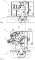
- Figure 9 shows a horizontal section through the representation according to Figure 8 , wherein the locking hook 8 can be seen with its pivot axis 85.
- the preloading unit 82 presses the engagement section 83 into the engagement position 80.
- the door is in the closed position 50 and the plunger 60 is shown in the contact position 62.
- FIG 10 shows the state 42 of the cooking device 1, the locking device 7 being in the extended position 71.
- the hook housing 9 is extended so that the appliance door 5 is moved into the position 51 which is open in the gap.
- the cooking space is opened in gaps so that rapid cooling can be carried out.
- rapid cooling is particularly advantageous if the food to be cooked is to remain in the cooking space and the cooking space is still at a high temperature level.
- the heat present in the cooking space can be effectively dissipated to the outside. This effectively prevents re-cooking.
- the motor 12 which is also not shown here, is activated, which engages with the toothing on the transmission link 13 via the pinion shaft 12a.
- the motor is specifically rotated in a certain direction of rotation until an end region of the first transmission section 14 is reached.
- the first transmission section practically serves to move the locking device 7 outwards or to withdraw it.
- the button 25a of the switch 25 is activated, so that the control of the cooking device 1 receives feedback about the position of the locking device 7.
- Figures 11 and 12 finally show a top view and an associated horizontal section of the door lock 3 when the cooking appliance 1 is in the fourth state 44.
- the door lock In this state, the door lock is in a locking position 30, in which manual opening and closing of the appliance door 5 is not possible.
- a pivoting of the locking hook 8 is prevented in that the locking hook 8 with its locking section 86 hooks onto the locking section 87 of the coupling 10, so that a transfer of the locking hook 8 into the release position 81 is not possible.
- the button 26a of the switch 26 is activated, so that the control system receives feedback that the locking hook and the door lock are in the locking position 30 as a whole.
- a locking position 30 is activated when, for example, a pyrolysis process is to be carried out.
- the coupling 10 is rotated in the opposite direction via the motor 12 and the pinion shaft 12a until the pinion shaft 12a is in the end region of the second transmission section 15.
- the invention provides an advantageous cooking device in which many functions can be implemented. Because the door lock has received the closing device so that it can be extended, the device door can be opened at least in gaps by extending the closing device. In a handle-less variant, the door can be easily opened by moving the locking hook from the engagement position to the release position. This opening process is independent of whether or not the appliance door is opened in columns with the closing device. The appliance door can be opened both from the closed position and from the gap-open position.
- the door lock for the cooking device according to the invention is of simple construction and of modular design. In this way, the same installation dimensions can be used for different variants.
- Reference list 1 Cooking appliance 31 Swivel axis of 10 2 Lock latch 32 Swivel position of 10 3 Door lock 33 Switching arm 4 Component, device housing 33a Axis of rotation of 33 5 Component, appliance door 34 Switching arm 6 Lock housing 34a Axis of rotation of 34 7 Locking device 41 first state 8th Locking hook 42 second state 9 Hook housing 43 third state 10 Paddock 44 fourth state 10a Switching arm 46 button 11 Drive means 50 closed position of 5 12 engine 51 gap open position of 5 12a Pinion shaft 52 Open position 13 Broadcasting backdrop 53 Opening direction 14 first transmission section 54 Spring device 15 second transmission section 55 hinge 18th Housing part, lower part of the hook housing 57 58 Swivel axis of door cover strip 18a Feather mount 60 Pestle 18b Feather mount 61 Vacancy of 60 19 Housing part, 62 Contact position from 60 Upper part of the hook housing 63 wall
Landscapes
- Engineering & Computer Science (AREA)
- Chemical & Material Sciences (AREA)
- Combustion & Propulsion (AREA)
- Mechanical Engineering (AREA)
- General Engineering & Computer Science (AREA)
- Electric Ovens (AREA)
- Cookers (AREA)
Description
- Die vorliegende Erfindung betrifft ein Gargerät und insbesondere einen pyrolysefähigen Backofen nach dem Oberbegriff des Anspruchs 1.
- Ein solches Gargerät ist aus der
DE 100 27 774 A1 bekannt. - Im Stand der Technik sind verschiedenste Gargeräte und pyrolysefähige Backöfen bekannt geworden, die über einen Türverschluss verschließbar sind.
- Mit der
EP 1 860 382 A2 ist eine Türverriegelung für ein Haushaltsgerät mit einem Schließkloben und einer Schlossfalle bekannt geworden, wobei der Schließkloben zwischen einer Schließlage, in der dieser mit der Schlossfalle verriegelt ist und die Tür im Wesentlichen dicht an dem Frontrahmen des Korpus oder einer daran angeordneten Türdichtung anliegt und einer Öffnungslage, in der die Tür nicht verriegelt ist, hin und her bewegbar ist. Der Schließkloben ist schwenkbar an dem Korpus aufgenommen und wird zur Überführung zwischen der Schließlage und der Öffnungslage um etwa 90° gedreht. Bei diesem bekannten Stand der Technik treibt ein Antriebsmotor eine Antriebsschnecke an, die mit einem Zahnrad zu Verschwenkung des Schließklobens gekoppelt ist. Die Türverriegelung des bekannten Haushaltsgeräts funktioniert grundsätzlich, bietet aber relativ wenig Funktionen. - Bei einem aus der
WO 2013/119 614 A1 bekannten Verschlusssystem für einen Ofen gibt es ein Paar identischer Verschlüsse, von denen eines im oberen Bereich und ein anderes im unteren Bereich einer um eine vertikale Achse schwenkbaren Tür angeordnet ist. Jeder Verschluss weist einen Hebel auf der sich über die Stirnseite der Tür hinaus erstreckt und beide Hebel sind durch einen stangenförmigen Handgriff miteinander verbunden. Die Hebel sind zwischen einer geschlossenen Position, einer gelösten Position und einer vollständig geöffneten Position bewegbar. In der gelösten Position ist die Tür spaltweise geöffnet. - Die
DE 100 27 774 A1 zeigt einen Backofen mit einem Schließkolben an der Tür, der in einen Schließkasten am Gehäuse eingreift. Damit die Tür spaltweise geöffnet werden kann, ist eines der Verschlusselemente beweglich am Gehäuse oder an der Tür befestigt. Die Tür verbleibt dann in dieser Stellung, bis eine Entriegelung erfolgt, die aus der spaltweise geöffneten Stellung eine vollständige Öffnung ermöglicht. - Ein aus der
EP 2 845 532 A1 bekanntes Haushaltgerät umfasst einen Gerätekorpus und einen Behandlungsraum mit einer Beschickungsöffnung, die durch eine Tür verschließbar ist. Ein Schubelement kann die Tür in Anpressrichtung verschieben, so dass ein Türverschluss entriegelt wird. Eine Öffnung der Tür kann dann durch eine Umkehr der Bewegungsrichtung des Schubelements, durch Federkraft oder eine Kombination davon hervorgerufen werden. - Aus der
GB 2 252 787 A - Auch die in der
DE 42 08 216 A1 und in derUS 4 960 297 A beschriebenen Türverschlüsse ermöglichen sowohl den vollständigen Verschluss der Tür als auch eine Zwischenstellung, in der die Tür spaltweise geöffnet werden kann. - Es ist deshalb die Aufgabe der vorliegenden Erfindung, ein Gargerät und insbesondere einen pyrolysefähigen Backofen mit einem Türverschluss zur Verfügung zu stellen, womit mehr Funktionen möglich sind.
- Diese Aufgabe wird gelöst durch das Gargerät mit den Merkmalen des Anspruchs 1. Bevorzugte Weiterbildungen der Erfindung sind Gegenstand der Unteransprüche. Weitere Vorteile und Merkmale der vorliegenden Erfindung ergeben sich aus der allgemeinen Beschreibung und der Beschreibung der Ausführungsbeispiele.
- Ein erfindungsgemäßes Gargerät ist insbesondere als pyrolysefähiger Backofen ausgebildet oder umfasst einen solchen. Das Gargerät umfasst mindestens zwei Bauteile, wobei ein Bauteil als Gerätegehäuse und ein Bauteil als Gerätetür ausgebildet ist. Die Gerätetür ist relativ zum Gerätegehäuse beweglich angeordnet. Das bedeutet, dass die Gerätetür am Gerätegehäuse schwenkbar gelagert sein kann, alternativ kann sie mit einem sogenannten Backwagen vom Gehäuse weg verfahrbar sein. Ein Türverschluss dient zum Verschließen der Gerätetür. In einem ersten Zustand befindet sich die Gerätetür in einer geschlossenen Stellung und der Türverschluss befindet sich in einer Eingriffsstellung im Eingriff mit der Gerätetür. In einem zweiten Zustand befinden sich die Gerätetür in einer wenigstens spaltweise geöffneten Stellung und der Türverschluss in der Eingriffsstellung im Eingriff mit der Gerätetür. In einem dritten Zustand befindet sich der Türverschluss in einer Freigabestellung und gibt die Gerätetür frei.
- Es ist vorgesehen, dass wenigstens ein Garprogramm hinterlegt ist oder programmierbar ist, bei welchem die spaltweise geöffnete Stellung während des Programmablaufes und/oder gegen Programmende ansteuerbar ist.
- Dabei wird die Gerätetür mit einer Federeinrichtung in Öffnungsrichtung vorbelastet. Das bedeutet, dass sich die Tür im dritten Zustand selbsttätig wenigstens spaltweise oder mehr öffnet.
- Die Gerätetür wird im dritten Zustand durch die Federkraft der Federeinrichtung geöffnet. Dabei kann eine Überführung der Gerätetür von der geschlossenen Stellung in die spaltweise geöffnete Stellung erfolgen. Es ist aber auch möglich, dass die Tür weiter als spaltweise geöffnet wird. Es kann eine nahezu vollständige oder auch vollständige Öffnung der Gerätetür erfolgen. Eine solche Ausgestaltung bietet sich beispielsweise bei grifflosen Varianten der Gerätetür bzw. des Gargeräts an.
- Das erfindungsgemäße Gargerät bietet viele Vorteile. Ein erheblicher Vorteil des erfindungsgemäßen Gargeräts besteht darin, dass mit dem Türverschluss eine Vielzahl von Funktionen zur Verfügung gestellt wird. Das Gargerät und insbesondere die Gerätetür, der Verschluss und das Gerätegehäuse sind in verschiedene Zustände überführbar. Die einzelnen Zustände werden jeweils durch die Stellungen der einzelnen Bauteile und Komponenten definiert. In einem ersten Zustand befinden sich die Gerätetür in einer geschlossenen Stellung und der Türverschluss in einer Eingriffsstellung mit der Gerätetür. Das bedeutet, dass die Gerätetür durch den Türverschluss gehalten wird. In in einem zweiten Zustand befinden sich die Gerätetür in einer wenigstens spaltweise und insbesondere spaltweise geöffneten Stellung, während der Türverschluss sich (immer noch) in der Eingriffsstellung im Eingriff mit der Gerätetür befindet. Das bedeutet, dass auch in dieser spaltweisen Öffnungsstellung die Gerätetür durch den Türverschluss gehalten wird. In einem dritten Zustand befindet sich der Türverschluss in einer Freigabestellung und gibt die Gerätetür frei. Dann kann die Gerätetür selbsttätig öffnen. In einer bevorzugten Weiterbildung umfasst der Türverschluss ein an einem ersten der Bauteile gelagertes Schlossgehäuse und eine Schlossfalle an dem zweiten Bauteil. Der Türverschluss umfasst vorzugsweise eine gegenüber dem Schlossgehäuse ausfahrbare Schließeinrichtung, welche insbesondere in dem zweiten Zustand ausgefahren ist. Vorzugsweise ist die Schließeinrichtung in dem ersten Zustand (teilweise oder auch vollständig) eingefahren. Das bedeutet, dass bei der Überführung von dem ersten Zustand in den zweiten Zustand die Schließeinrichtung aus der (weiter) eingefahrenen Stellung in die (weiter) ausgefahrene Stellung überführt wird. Dabei kann der Türverschluss in der Eingriffsstellung verbleiben und sich im Eingriff mit der Gerätetür befinden.
- Erfindungsgemäß ist ein Antriebsmittel vorgesehen, um den ersten Zustand in den zweiten Zustand und umgekehrt zu überführen. Dabei wird insbesondere die Gerätetür von der geschlossenen Stellung in die spaltweise geöffnete Stellung und/oder von der spaltweise geöffneten Stellung (wieder zurück) in die geschlossene Stellung überführt, während sich der Türverschluss (vorzugsweise fortwährend) in der Eingriffsstellung befindet. Ein Antriebsmittel zur gesteuerten Überführung in den ersten Zustand und den zweiten Zustand und/oder zurück bietet erhebliche Vorteile, da es im Programmablauf die gezielte Öffnung der Gerätetür ermöglicht. Es kann auch ein gesteuertes Schließen der Gerätetür durchgeführt werden.
- Erfindungsgemäß erfolgt eine Überführung von dem ersten Zustand in den zweiten Zustand mittels des Antriebsmittels langsamer als eine Öffnung der Gerätetür durch die Federkraft der Federeinrichtung im dritten Zustand. Vorzugsweise wird der erste Zustand in den zweiten Zustand mit dem Antriebsmittel innerhalb von 15 bis 90 Sekunden und vorzugsweise innerhalb von 25 bis 60 Sekunden überführt. Im dritten Zustand wird die Gerätetür mittels der Federkraft der Federeinrichtung von der geschlossenen Stellung in die wenigstens spaltweise geöffnete Stellung innerhalb von weniger als 15 Sekunden und insbesondere innerhalb von weniger als 10 Sekunden überführt. Eine Öffnung ist auch innerhalb von 5 Sekunden oder 4 Sekunden möglich und bevorzugt.
- Wenn die Gerätetür mittels der Federkraft der Federeinrichtung geöffnet werden kann, ist die Gerätetür vorzugsweise grifflos ausgebildet. Dann kann durch Drücken einer Taste oder programmgesteuert eine Öffnung der Tür wenigstens spaltweise oder vollständig erfolgen.
- In bevorzugten Ausgestaltungen ist die Gerätetür von dem zweiten Zustand durch Aufbringung von Zug- oder Druckkraft in die geschlossene Stellung oder in eine weiter geöffnete Stellung überführbar. Eine weiter geöffnete Stellung kann beispielsweise die (nahezu) vollständig geöffnete Stellung sein.
- Wenn die Gerätetür manuell durch Aufbringung von Zug- oder Druckkraft aus der spaltweise geöffneten Stellung in die vollständig geöffnete Stellung oder in die geschlossene Stellung überführt werden kann, ermöglicht das einen flexiblen manuellen Eingriff durch den Benutzer. Wenn der Benutzer beispielsweise feststellt, dass das Gargut fertig zubereitet ist, kann er die Gerätetür vollständig öffnen, um das Gargut zu entnehmen.
- Eine spaltweise Öffnung der Gerätetür erfolgt durch das Programm gesteuert vorzugsweise dann, wenn ein sogenanntes Schnellabkühlen durchgeführt werden soll, bei dem die in dem Garraum vorhandene Wärme möglichst schnell abgeführt werden soll, um ein Weitergaren des Gargutes zu verhindern. Es ist möglich, dass die Temperatur im Garraum auf ein solches Niveau abgesenkt wird, dass das Gargut passend temperiert für den Verzehr ist. Bei einer solchen Programmierung ist es sinnvoll, dass der Benutzer ohne das Betätigen von Tasten oder Sensoren einfach die Gerätetür ergreifen und weiter öffnen kann, um das Gargut zu entnehmen. Falls der Benutzer dann feststellt, dass er das Gargut lieber im Garraum belassen will, kann er die Gerätetür gegebenenfalls wieder in die spaltweise geöffnete Stellung verbringen und mit der Schließeinrichtung verrasten.
- Vorzugsweise ist eine Taste oder dergleichen vorgesehen (Taster, Sensor etc.), wobei bei Betätigung der Taste ein Überführen der Gerätetür in die spaltweise geöffnete Stellung und/oder eine weiter geöffnete Stellung (automatisch) veranlasst wird.
- In allen Ausgestaltungen ist es bevorzugt, dass ein vierter Zustand vorgesehen ist, in welchem der Türverschluss verriegelt und die Gerätetür geschlossen sind. Ein solcher vierter Zustand ist insbesondere vorteilhaft, wenn das Gargerät für eine Pyrolysefunktion vorgesehen ist und ein Pyrolyseprogramm hinterlegt ist. Bei Aktivierung eines Pyrolyseprogramms wird vorzugsweise der vierte Zustand aktiviert. Dabei wird die Gerätetür (aktiv) geschlossen und der Türverschluss (aktiv) verriegelt, sodass in diesem Zustand eine Öffnung der Tür durch den Nutzer manuell nicht mehr möglich ist.
- Weitere Vorteile und Merkmale ergeben sich aus den Ausführungsbeispielen, die im Folgenden mit Bezug auf die beiliegenden Figuren erläutert werden.
- In den Figuren zeigen:
- Figur 1
- eine schematische perspektivische Ansicht eines erfindungsgemäßen Gargeräts in einem ersten Zustand;
- Figur 2
- das Gargerät gemäß
Figur 1 in einem zweiten Zustand; - Figur 3
- das Gargerät aus
Figur 1 in einem dritten Zustand; - Figur 4
- den Türverschluss des Gargeräts aus
Figur 1 in einer ersten Ausführungsform in einer perspektivischen Darstellung; - Figur 5
- einen anderen Türverschluss für das Gargerät nach
Figur 1 in einer grifflosen Variante; - Figur 6
- den Türverschluss aus
Figur 4 in einer Explosionsdarstellung; - Figur 7
- schematische Draufsicht auf den Türverschluss nach
Figur 4 in der Leerstellung; - Figur 8
- eine schematische Draufsicht auf den Türverschluss nach
Figur 4 bei geschlossener Tür; - Figur 9
- den Türverschluss gemäß
Figur 8 in einem Horizontalschnitt; - Figur 10
- den Türverschluss gemäß
Figur 4 bei einer spaltweise geöffneten Gerätetür; - Figur 11
- den Türverschluss gemäß
Figur 4 in der Pyrolysestellung; und - Figur 12
- einen Horizontalschnitt durch die Darstellung gemäß
Figur 11 . - Mit Bezug auf die beiliegenden Figuren werden im folgenden Varianten eines erfindungsgemäßen Gargeräts erläutert.
Figuren 1 bis 3 zeigen verschiedene Zustände 41 - 43 des Gargeräts 1 bzw. des Türverschlusses 3 und der Gerätetür 5.Figur 1 zeigt dabei eine stark schematische perspektivische Darstellung des Gargeräts 1, wobei das Gargerät 1 über ein Gerätegehäuse 4 und eine Gerätetür 5 verfügt. Die Gerätetür 5 ist über Scharniere 55 um eine hier horizontal ausgerichtete Schwenkachse 57 schwenkbar an dem Gerätegehäuse 4 aufgenommen. Alternativ kann sie zusammen mit einem sogenannten Backwagen vom Gerätegehäuse 4 weg verfahren werden (nicht dargestellt). Oberhalb des Garraums ist die Gerätekühlung vorgesehen. Im Bereich der Gerätekühlung ist der Türverschluss 3 befestigt, wobei hier das Schlossgehäuse 6 an dem Gerätegehäuse 4 befestigt ist und die Schlossfalle 2 an der Gerätetür 5 ausgebildet ist. -
Figur 1 zeigt das Gargerät in dem Zustand 41, wobei sich die Gerätetür 5 in der geschlossenen Stellung 50 befindet. Der Türverschluss 3 bzw. die Schließeinrichtung 7 (vergleicheFigur 4 ) des Türverschlusses 3 befindet sich inFigur 1 in der Schließstellung 70. - Die Gerätetür 5 kann durch Federeinrichtungen 54 zum Beispiel an den Scharnieren 55 in die geöffnete oder die geschlossene Stellung 50 der Gerätetür 5 vorbelastet sein. Jedenfalls wird die Gerätetür 5 in dem Zustand 41 gemäß
Figur 1 von dem Geräteverschluss 3 gehalten. - Wenn das Gargerät 1 mit einer grifflosen Tür ausgerüstet ist, kann durch Betätigung der Taste 46 die Gerätetür 5 automatisch geöffnet werden.
-
Figur 2 zeigt eine stark schematische Seitenansicht des Gargeräts 1 ausFigur 1 , wobei das Gargerät sich in dem Zustand 42 befindet. In dem Zustand 42 befindet sich der Türverschluss 3 bzw. der Schließhaken 8 in der Eingriffsstellung 80 und steht im Eingriff mit der Gerätetür 5. Die Gerätetür 5 ist in der Darstellung gemäßFigur 2 in Öffnungsrichtung 53 spaltweise geöffnet. Der Schließhaken 8 bzw. der Türverschluss 3 befinden sich aber im Eingriff mit der Gerätetür 5, sodass die Gerätetür 5 in der spaltweise geöffneten Stellung 51 fixiert wird. InFigur 2 befindet sich die Schließeinrichtung 7 in der ausgefahrenen Stellung 71. Das Einfahren und Ausfahren der Schließeinrichtung 7 wird insbesondere über ein Antriebsmittel 11 angetrieben. - Wenn in der Darstellung gemäß
Figur 2 der Schließhaken 8 in die Freigabestellung 81 überführt wird und wenn die Gerätetür in die Öffnungsrichtung 53 vorbelastet ist, so öffnet sich nach der Überführung des Schließhakens in die Freigabestellung 81 die Gerätetür 5 automatisch, sodass sich ein Zustand 43 ergibt, wie er inFigur 3 dargestellt ist. Die Gerätetür befindet sich dann in einer weiter geöffneten Stellung 52. Diese weiter geöffnete Stellung 52 kann die vollständig geöffnete Position der Gerätetür sein. - In
Figur 3 ist die Schließeinrichtung 7 wieder in der Schließstellung bzw. in der eingefahrenen Stellung 70 abgebildet. -
Figur 4 zeigt eine perspektivische Draufsicht auf einen Türverschluss 3, der ein Schlossgehäuse 6 umfasst, welches dafür vorgesehen ist, an dem Gerätegehäuse 4 befestigt zu werden. Die Schlossfalle 2 ist an der Gerätetür vorgesehen, von der hier nur die Türabdeckleiste 58 zu sehen ist. - Das Hakengehäuse 9 des Türverschlusses 3 ist in die Schlossfalle 2 eingetaucht. Der Schließhaken 8 ist seitlich aus dem Hakengehäuse 9 heraus geschwenkt und befindet sich in der Eingriffsstellung 80, in der die Gerätetür 5 von dem Türverschluss 3 in der gegebenen Stellung gehalten wird.
- Schalter 24, 25 und 26 sind zur Erkennung unterschiedlicher Positionen vorgesehen. Zur Ansteuerung verschiedener Positionen und Zustände ist ein Motor 12 vorgesehen, der auf die Schließeinrichtung 7 einwirkt.
-
Figur 5 zeigt eine alternative Ausgestaltung, bei der der Türverschluss 3 für den Einsatz einer grifflosen Tür vorbereitet ist. Der Türverschluss 3 umfasst zusätzlich zu der Ausgestaltung gemäßFigur 4 noch ein aktives Betätigungselement 20, welches beispielsweise als Synchronmotor ausgeführt sein kann und zur aktiven Freigabe der Gerätetür dient. Durch das Antriebsmittel 20 kann für eine vollständige und nicht nur eine spaltweise Öffnung der Gerätetür 5 gesorgt werden. -
Figur 6 zeigt eine Explosionsdarstellung des Türverschlusses 3 ausFigur 4 . Das unterste dargestellte Bauteil ist das Schlossgehäuse 6, welches hier an dem Gerätegehäuse 4 befestigt wird. An dem Schlossgehäuse 6 wird das Hakengehäuse 9 aufgenommen, welches aus dem Hakengehäuse-Unterteil 18 und dem Hakengehäuse-Oberteil 19 besteht. An dem Hakengehäuse-Unterteil 18 ist unter anderem eine Federaufnahme 18a zu erkennen, an der im montierten Zustand eine Vorbelastungseinheit 82 angeordnet ist, um den Schließhaken 8 in die Eingriffsstellung 80 vorzubelasten (vergleicheFigur 9 ). - In dem Hakengehäuse 9 ist der Schließhaken 8 verschwenkbar aufgenommen. Der Schließhaken 8 ist schwenkbar um eine Schwenkachse 85 des Unterteils 18 gelagert und verfügt an einem Ende über einen Eingriffsabschnitt 83 und am anderen Ende über einen Ausleger 84. Zwischen dem Ausleger 84 und der Federaufnahme 18a befindet sich montierten Zustand die Vorbelastungseinheit 82.
- Bei dieser Ausgestaltung sind drei verschiedene Schalter 24, 25 und 26 vorgesehen, die jeweils über einen der Taster 24a, 25a und 26a verfügen. Der Schalter 24 und dessen Taster 24a wird außerhalb der verriegelten und außerhalb der ausgefahrenen Stellung aktiviert. Der Schalter 24 zeigt die Eingriffsstellung 80 des Türverschlusses 3 an, in der die üblichen Backofenfunktionen wie Backen, Braten und Grillen stattfinden. Wenn die Gerätetür 5 geschlossen und verriegelt ist (Pyrolysestellung), ist der Schalter 24 nicht mehr betätigt. Darüber kann eine Sicherheitsabfrage durchgeführt werden. Der Schalter 25 bzw. dessen Taster 25a wird aktiviert, wenn sich die Schließeinrichtung 7 in der ausgefahrenen Stellung 71 befindet. Darüber kann detektiert werden, ob sich die Tür in der spaltweise geöffneten Stellung 51 befindet. Die Stellung 71 zeigt an, dass die Gerätetür spaltweise geöffnet ist, um z. B. ein Schnellabkühlen durchzuführen und kann deshalb auch Schnellabkühlen-Stellung genannt werden. Der Schalter 26 bzw. dessen Taster 26a wird aktiviert, wenn sich das Gargerät in Zustand 44 befindet und sich der Schließhaken 8 bzw. der Türverschluss 3 in der Verriegelungsstellung 30 befindet (vergleiche
Figur 12 ). - Das Oberteil 19 des Hakengehäuses verfügt an seinem vorderen Ende über einen Stößel 60, der über zwei wendelförmige Federn 64 in die ausgefahrene Stellung vorbelastet ist. Dargestellt ist in
Figur 6 nur eine der beiden identischen wendelförmigen Federn 64. Zwei Federn 64 sind im montierten Zustand an den Federaufnahmen 18b in dem Unterteil 18 des Hakengehäuses 9 aufgenommen und drücken gegen das (hintere) Ende des Oberteils 19. Das Oberteil 19 ist gegenüber dem Unterteil des Hakengehäuses 9 bewegbar, sodass der Stößel 60 aus dem Hakengehäuse 9 nach vorn ausfährt, wenn die Gerätetür 5 nicht in Kontakt mit dem Hakengehäuse 9 steht. - An dem Oberteil ist ein Steg oder eine Wand 63 ausgebildet. Diese Wand 63 blockiert in der ausgefahrenen Leerstellung 61 oder Nullstellung des Stößels 60 eine Drehbewegung der Koppel 10, sodass ein Pyrolysebetrieb nicht gestartet werden kann. Durch die mechanische Blockierung kann die Koppel 10 nicht so weit drehen, dass der Schalter 26 für die Verriegelung betätigt wird. Eine Verriegelung der Gerätetür 5 deshalb kann nicht erreicht werden, wenn der Stößel ausgefahren ist.
- Oberhalb des Oberteils 19 ist die Koppel 10 abgebildet, auf die der Motor 12 über die Ritzelwelle 12a einwirkt. Durch Drehen des Motors 12 wird über die Ritzelwelle 12a und das daran ausgebildete Zahnrad die Drehbewegung auf die Verzahnung in der Übertragungskulisse 13 übertragen, die über 2 zueinander gewinkelte Übertragungsabschnitte 14 und 15 verfügt. Die Koppel 10 ist um die Schwenkachse 31 schwenkbar. Die Koppel 10 wirkt im montierten Zustand auf Schaltarme 33 und 34 ein, die wiederum über Schaltflächen 22 und 23 verfügen, um in entsprechenden Stellungen die Schalter 25 oder 26 zu aktivieren. Der Schaltarm 33 ist an der Aufnahme 33a im Schlossgehäuse 6 drehbar aufgenommen und der Schaltarm 34 ist drehbar an der Aufnahme 34a im Schlossgehäuse 6 abgestützt. Dabei dient die Schaltfläche 22 zur Ansteuerung des Schalters 25, während die Schaltfläche 23 zur Ansteuerung des Schalters 26 dient. An der Koppel ist der Schaltarm 10a mit der Schaltfläche 21 zur Ansteuerung des Schalters 24 ausgebildet. Eine Rückstellung der (leichtgängigen) Schaltarme 33 und 34 erfolgt hier durch die Rückstellkraft der Taster 25a und 26a.
-
Figur 7 zeigt den Türverschluss 3 in einer Draufsicht, wobei sich das Gargerät 1 in dem Zustand 43 befindet, in dem die Gerätetür 5 außer Eingriff mit dem Gerätegehäuse ist. Der Stößel 60 befindet sich deshalb in der ausgefahrenen Leerstellung 61. Der Eingriffsabschnitt 83 des Schließhakens 8 ist seitlich aus dem Hakengehäuse 9 ausgetaucht, nachdem die Gerätetür 5 freigegeben und geöffnet wurde. Anschließend fährt der Schließhaken 8 wieder aus, wenn die Gerätetür an dem Schließhaken 8 vorbeigeschwenkt ist. - Die Schließeinrichtung 7, die das Hakengehäuse 9 und auch die Koppel 10 umfasst befindet sich in der Schließstellung 70 bzw. der eingefahrenen Stellung. In dieser Stellung ist die Ritzelwelle 12a des hier nicht dargestellten Motors 12 etwa mittig im Eingriff an dem zweiten Übertragungsabschnitt 15 der Übertragungskulisse 13. Der erste und der zweite Übertragungsabschnitt 14 und 15 sind zueinander gewinkelt und weisen einen Winkel zwischen etwa 60 und 90° zueinander auf.
- In dieser Draufsicht ist auch die Schwenkachse 85 für den Schließhaken 8 zu erkennen.
-
Figur 8 zeigt eine schematische Draufsicht auf den Türverschluss 3, wobei auch hier Komponenten wie der Motor 12 und auch die Schaltarme 33, 34 weggelassen wurden, um die Übersicht zu verbessern. In der Darstellung gemäßFigur 8 befindet sich die Schließeinrichtung 7 in der eingefahrenen Stellung bzw. der Schließstellung 70. Der Stößel 60 befindet sich in der Kontaktstellung 62 bzw. in der eingefahrenen Stellung und das Oberteil 19 des Hakengehäuses ist zusammen mit dem Stößel 60 zurückbewegt worden. - Der Eingriffsabschnitt 83 des Schließhakens 8 greift in die Schlossfalle 2 ein und sichert so die Gerätetür 5 in der geschlossenen Position 50.
-
Figur 9 zeigt ein Horizontalschnitt durch die Darstellung gemäßFigur 8 , wobei der Schließhaken 8 mit seiner Schwenkachse 85 zu sehen ist. Die Vorbelastungseinheit 82 drückt den Eingriffsabschnitt 83 in die Eingriffsstellung 80. Die Tür befindet sich in der geschlossenen Stellung 50 und der Stößel 60 ist in der Kontaktstellung 62 eingezeichnet. - Zu Erkennen ist in
Figur 9 auch die Schwenkachse 31 der hier nicht weiter dargestellten Koppel 10. -
Figur 10 zeigt den Zustand 42 des Gargeräts 1, wobei sich die Schließeinrichtung 7 in der ausgefahrenen Stellung 71 befindet. Durch das Ausfahren der Schließeinrichtung 7 wird das Hakengehäuse 9 ausgefahren, sodass die Gerätetür 5 in die spaltweise geöffnete Stellung 51 überführt wird. In dieser Stellung ist der Garraum spaltweise geöffnet, sodass ein Schnellabkühlen durchgeführt werden kann. Ein solches Schnellabkühlen ist besonders vorteilhaft, wenn das Gargut noch in dem Garraum verbleiben soll und sich der Garraum aber noch auf einem hohen Temperaturniveau befindet. Durch ein gezieltes aktives Öffnen der Gerätetür 5 (und gleichzeitiges Aktivieren entsprechender Lüfter) kann die im Garraum vorhandene Wärme effektiv nach außen abgeführt werden. Dadurch kann ein Nachgaren effektiv verhindert werden. - Zum Überführen der Schließeinrichtung 7 in die ausgefahrene Stellung 71 wird der hier ebenfalls nicht dargestellte Motor 12 aktiviert, der über die Ritzelwelle 12a im Eingriff mit der Verzahnung an der Übertragungskulisse 13 steht. Der Motor wird gezielt in eine bestimmte Drehrichtung gedreht, bis ein Endbereich des ersten Übertragungsabschnitts 14 erreicht wird. Der erste Übertragungsabschnitt dient praktisch dazu, die Schließeinrichtung 7 nach außen zu bewegen oder zurückzuziehen.
- Obwohl in dem Zustand 42 gemäß
Figur 10 die Gerätetür sich in der spaltweise geöffneten Stellung 51 befindet, steht der Eingriffsabschnitt 83 noch im Eingriff mit der Schlossfalle 2 an der Gerätetür 5. - In der dargestellten Stellung ist der Taster 25a des Schalters 25 aktiviert, sodass die Steuerung des Gargeräts 1 eine Rückmeldung über die Position der Schließeinrichtung 7 erhält.
-
Figuren 11 und 12 zeigen schließlich eine Draufsicht und einen zugehörigen Horizontalschnitt des Türverschlusses 3, wenn sich das Gargerät 1 in dem vierten Zustand 44 befindet. In diesem Zustand befindet sich der Türverschluss in einer Verriegelungsstellung 30, in der ein manuelles Öffnen und Schließen der Gerätetür 5 nicht möglich ist. Eine Verschwenkung des Schließhakens 8 wird dadurch verhindert, dass sich der Schließhaken 8 mit seinem Verriegelungsabschnitt 86 an dem Verrieglungsabschnitt 87 der Koppel 10 verhakt, sodass eine Überführung des Schließhakens 8 in die Freigabestellung 81 nicht möglich ist. - In dem Zustand 44 ist der Taster 26a des Schalters 26 aktiviert, sodass die Steuerung eine Rückmeldung darüber erhält, dass sich der Schließhaken und der Türverschluss insgesamt in der Verriegelungsstellung 30 befinden. Eine solche Verriegelungsstellung 30 wird aktiviert, wenn beispielsweise ein Pyrolysevorgang durchgeführt werden soll.
- Um diese Stellung zu erreichen, wird über den Motor 12 und die Ritzelwelle 12a die Koppel 10 in die entgegengesetzte Richtung gedreht, bis sich die Ritzelwelle 12a im Endbereich des zweiten Übertragungsabschnitts 15 befindet.
- Insgesamt stellt die Erfindung ein vorteilhaftes Gargerät zur Verfügung, bei dem viele Funktionen realisiert werden können. Dadurch, dass der Türverschluss die Schließeinrichtung ausfahrbar aufgenommen hat, kann durch Ausfahren der Schließeinrichtung die Gerätetür wenigstens spaltweise geöffnet werden. Bei einer grifflosen Variante kann durch Überführung des Schließhakens von der Eingriffsstellung in die Freigabestellung ein einfaches Öffnen der Tür erreicht werden. Dieser Öffnungsvorgang ist unabhängig davon, ob mit der Schließeinrichtung die Gerätetür spaltweise geöffnet wird oder nicht. Ein Öffnen der Gerätetür ist sowohl aus der geschlossenen Stellung als auch aus der spaltweise geöffneten Stellung möglich.
- Mit dem erfindungsgemäßen Gargerät ist es möglich, die Gerätetür nicht nur spaltweise zu öffnen, sondern anschließend auch wieder zu schließen. Ein solcher Öffnungs- oder Schließvorgang kann gegen Ende eines Automatikprogramms oder auch am Anfang oder im mittleren Bereich des Programms erfolgen.
- Der Türverschluss für das erfindungsgemäße Gargerät ist einfach aufgebaut und modular ausgestaltet. So können gleiche Einbaumaße für unterschiedliche Varianten verwendet werden.
Bezugszeichenliste 1 Gargerät 31 Schwenkachse von 10 2 Schlossfalle 32 Schwenkstellung von 10 3 Türverschluss 33 Schaltarm 4 Bauteil, Gerätegehäuse 33a Drehachse von 33 5 Bauteil, Gerätetür 34 Schaltarm 6 Schlossgehäuse 34a Drehachse von 34 7 Schließeinrichtung 41 erster Zustand 8 Schließhaken 42 zweiter Zustand 9 Hakengehäuse 43 dritter Zustand 10 Koppel 44 vierter Zustand 10a Schaltarm 46 Taste 11 Antriebsmittel 50 geschlossene Stellung von 5 12 Motor 51 spaltweise geöffnete Stellung von 5 12a Ritzelwelle 52 Offenstellung 13 Übertragungskulisse 53 Öffnungsrichtung 14 erster Übertragungsabschnitt 54 Federreinrichtung 15 zweiter Übertragungsabschnitt 55 Scharnier 18 Gehäuseteil, Hakengehäuse-Unterteil 57 58 Schwenkachse Türabdeckleiste 18a Federaufnahme 60 Stößel 18b Federaufnahme 61 Leerstellung von 60 19 Gehäuseteil, 62 Kontaktstellung von 60 Hakengehäuse-Oberteil 63 Wand 20 aktives Betätigungselement 64 Feder 21 Schaltfläche 70 Schließstellung von 7 22 Schaltfläche 71 ausgefahrene Stellung von 7 23 Schaltfläche 80 Eingriffsstellung von 8 24 Schalter für 80 81 Freigabestellung von 8 24a Taster 82 Vorbelastungseinheit für 8 25 Schalter für 71 83 Eingriffsabschnitt 25a Taster 84 Ausleger 26 Schalter 85 Schwenkachse 26a Taster 86 Verriegelungsabschnitt von 8 30 Verriegelungsstellung 87 Verriegelungsabschnitt von 10
Claims (11)
- Gargerät (1), insbesondere pyrolysefähiger Backofen, mit mindestens zwei Bauteilen (4, 5), wobei ein Bauteil als Gerätegehäuse (4) und ein Bauteil als Gerätetür (5) ausgebildet ist und wobei die Gerätetür (5) relativ zum Gerätegehäuse (4) beweglich angeordnet ist, und mit einem Türverschluss (3),• wobei sich in einem ersten Zustand (41) die Gerätetür (5) in einer geschlossenen Stellung (50) und der Türverschluss (3) in einer Eingriffsstellung (80) im Eingriff mit der Gerätetür (5) befinden,• wobei sich in einem zweiten Zustand (42) die Gerätetür (5) in einer wenigstens spaltweise geöffneten Stellung (51) und der Türverschluss (3) in der Eingriffsstellung (80) im Eingriff mit der Gerätetür (5) befinden, wobei ein Antriebsmittel (11) vorgesehen ist, um den ersten Zustand (41) in den zweiten Zustand (42) und umgekehrt zu überführen, und wobei wenigstens ein Garprogramm hinterlegt ist, bei welchem die spaltweise geöffnete Stellung (51) während des Programmablaufes und/oder gegen Programmende ansteuerbar ist,• wobei sich in einem dritten Zustand (43) der Türverschluss (3) in einer Freigabestellung (81) befindet und die Gerätetür (5) freigibt,dadurch gekennzeichnet,
dass die Gerätetür (5) mit einer Federreinrichtung (54) in Öffnungsrichtung (53) vorbelastet wird, dass durch die Federkraft der Federreinrichtung (54) die Gerätetür (5) im dritten Zustand (43) geöffnet wird und eine Überführung von dem ersten Zustand (41) in den zweiten Zustand (42) mittels des Antriebsmittels (11) langsamer erfolgt als eine Öffnung der Gerätetür (5) durch die Federkraft der Federreinrichtung (54) im dritten Zustand (43). - Gargerät (1) nach dem vorhergehenden Anspruch, wobei der erste Zustand (41) in den zweiten Zustand (42) mit dem Antriebsmittel (11) innerhalb von 15 bis 90 Sekunden und insbesondere innerhalb von 25 Sekunden bis 60 Sekunden überführbar ist.
- Gargerät (1) nach einem der vorhergehenden Ansprüche, wobei im dritten Zustand (43) die Gerätetür (5) mittels der Federkraft der Federreinrichtung (54) von der geschlossenen Stellung (50) in die wenigstens spaltweise geöffnete Stellung (51) innerhalb von weniger als 15 Sekunden und insbesondere innerhalb von weniger als 10 Sekunden erfolgt.
- Gargerät (1) nach einem der vorhergehenden Ansprüche, wobei der Türverschluss (3) ein an einem ersten der Bauteile (4) gelagertes Schlossgehäuse (6) und eine Schlossfalle (2) an dem zweiten Bauteil (5) umfasst und wobei der Türverschluss (3) eine gegenüber dem Schlossgehäuse (6) ausfahrbare Schließeinrichtung (7) umfasst, welche in dem zweiten Zustand (42) ausgefahren ist.
- Gargerät (1) nach dem vorhergehenden Anspruch, wobei die Schließeinrichtung (7) in dem ersten Zustand (41) eingefahren ist.
- Gargerät (1) nach einem der vorhergehenden Ansprüche, wobei ein Antriebsmittel (11) vorgesehen ist, um den ersten Zustand (41) in den zweiten Zustand (42) und umgekehrt zu überführen.
- Gargerät (1) nach einem der vorhergehenden Ansprüche, wobei die Gerätetür (5) grifflos ausgebildet ist.
- Gargerät (1) nach einem der vorhergehenden Ansprüche, wobei die Gerätetür (5) in dem zweiten Zustand (42) durch Aufbringung von Zug- oder Druckkraft in die geschlossene Stellung (50) oder in eine weiter geöffnete Stellung (52) überführbar ist.
- Gargerät (1) nach einem der vorhergehenden Ansprüche, wobei eine Taste (46) vorgesehen ist, deren Betätigung ein Überführen der Gerätetür (5) in eine weiter geöffnete Stellung (52) veranlasst.
- Gargerät (1) nach einem der vorhergehenden Ansprüche, wobei in einem vierten Zustand (44) der Türverschluss (3) verriegelt und die Gerätetür (5) geschlossen ist.
- Gargerät (1) nach dem vorhergehenden Anspruch, wobei ein Pyrolyseprogramm hinterlegt ist, bei welchem der vierte Zustand (44) aktiviert wird.
Priority Applications (1)
| Application Number | Priority Date | Filing Date | Title |
|---|---|---|---|
| PL17196051T PL3324125T3 (pl) | 2016-11-16 | 2017-10-12 | Urządzenie do gotowania z zamknięciem drzwiowym |
Applications Claiming Priority (1)
| Application Number | Priority Date | Filing Date | Title |
|---|---|---|---|
| DE102016122011 | 2016-11-16 |
Publications (2)
| Publication Number | Publication Date |
|---|---|
| EP3324125A1 EP3324125A1 (de) | 2018-05-23 |
| EP3324125B1 true EP3324125B1 (de) | 2020-03-04 |
Family
ID=60083173
Family Applications (1)
| Application Number | Title | Priority Date | Filing Date |
|---|---|---|---|
| EP17196051.1A Active EP3324125B1 (de) | 2016-11-16 | 2017-10-12 | Gargerät mit türschloss |
Country Status (3)
| Country | Link |
|---|---|
| EP (1) | EP3324125B1 (de) |
| ES (1) | ES2781298T3 (de) |
| PL (1) | PL3324125T3 (de) |
Cited By (1)
| Publication number | Priority date | Publication date | Assignee | Title |
|---|---|---|---|---|
| WO2025040382A1 (de) * | 2023-08-23 | 2025-02-27 | Miele & Cie. Kg | Gargerät mit einer funktion eines schnellabkühlens eines garraums |
Families Citing this family (2)
| Publication number | Priority date | Publication date | Assignee | Title |
|---|---|---|---|---|
| DE102019115157B4 (de) * | 2019-06-05 | 2021-03-18 | Miele & Cie. Kg | Schaltervorrichtung für ein Gargerät mit einem durch eine Tür verschließbaren Garraum und Gargerät |
| BE1029396B1 (de) | 2021-05-11 | 2022-12-12 | Miele & Cie | Verfahren zum Kühlen des austretenden Wrasens oder Dampfs aus dem Garraum eines Gargeräts und Gargerät |
Family Cites Families (6)
| Publication number | Priority date | Publication date | Assignee | Title |
|---|---|---|---|---|
| US4960297A (en) * | 1989-09-28 | 1990-10-02 | Component Hardware Group, Inc. | Double action latch |
| GB2252787B (en) * | 1991-02-12 | 1995-02-08 | Stoves Ltd | Improvements in or relating to door hinge mechanisms |
| DE4208216A1 (de) * | 1992-03-14 | 1993-09-16 | Wiesheu Gmbh | Tuerverschluss fuer geraete |
| DE10027774C2 (de) * | 2000-04-20 | 2003-08-21 | Miwe Michael Wenz Gmbh | Vorrichtung zum Schließen der Tür eines Ofens und Ofen |
| GB2584061B (en) * | 2012-02-07 | 2021-03-03 | Southco | Lever actuated compression latch |
| DE102013109620A1 (de) * | 2013-09-04 | 2015-03-05 | Miele & Cie. Kg | Haushaltgerät mit automatischem Türöffnungsmechanismus |
-
2017
- 2017-10-12 PL PL17196051T patent/PL3324125T3/pl unknown
- 2017-10-12 ES ES17196051T patent/ES2781298T3/es active Active
- 2017-10-12 EP EP17196051.1A patent/EP3324125B1/de active Active
Non-Patent Citations (1)
| Title |
|---|
| None * |
Cited By (1)
| Publication number | Priority date | Publication date | Assignee | Title |
|---|---|---|---|---|
| WO2025040382A1 (de) * | 2023-08-23 | 2025-02-27 | Miele & Cie. Kg | Gargerät mit einer funktion eines schnellabkühlens eines garraums |
Also Published As
| Publication number | Publication date |
|---|---|
| EP3324125A1 (de) | 2018-05-23 |
| PL3324125T3 (pl) | 2020-07-13 |
| ES2781298T3 (es) | 2020-09-01 |
Similar Documents
| Publication | Publication Date | Title |
|---|---|---|
| EP3045639B1 (de) | Scharnier für ein haushaltsgerät sowie verfahren zum betreiben eines solchen scharniers | |
| EP2845532B1 (de) | Haushaltgerät mit automatischem Türöffnungsmechanismus | |
| DE102004061231B3 (de) | Türverriegelung für einen Herd | |
| EP2594713B1 (de) | Türöffner | |
| EP3261507B1 (de) | Spülmaschine | |
| DE102012020631A1 (de) | Gargerät | |
| EP3534752B1 (de) | Möbel mit einem motorischen antrieb für ein möbelteil sowie motorischer antrieb für ein möbel | |
| EP3324124B1 (de) | Gargerät mit türschloss | |
| EP2822442A2 (de) | Haushaltsgerät | |
| DE102019003360B4 (de) | Fahrzeug-Türsystem mit Türöffner | |
| EP3324125A1 (de) | Gargerät mit türschloss | |
| DE102011084571A1 (de) | Vorrichtung zur Behandlung von Lebensmitteln mit verbesserter Tür-Anbindung | |
| EP2741015B1 (de) | Tür für ein Haushaltsgerät mit einem plattenartigen Greifteil und einem Greifteilöffner, Haushaltsgerät mit einer derartigen Tür sowie Verfahren zum Öffnen einer Tür eines Haushaltsgeräts | |
| DE102017211203B4 (de) | Hebesystem für eine Haushaltsgeschirrspülmaschine oder ein Möbel | |
| EP3324126B1 (de) | Gargerät mit türverschluss | |
| EP2765861B1 (de) | Vorrichtung zur behandlung von lebensmitteln mit tür-reinigungsstellung | |
| EP2732113B1 (de) | Verschluss zum verschliessen einer tür, insbesondere einer gerätetür | |
| DE102011085447A1 (de) | Haushaltsmaschine | |
| DE102011084570B4 (de) | Vorrichtung zur Behandlung von Lebensmitteln mit Tür-Schiebemechanismus | |
| DE69429738T2 (de) | Verriegelungsvorrichtung für eine Backofentür | |
| EP0339294B1 (de) | Beschlag für einen zumindest kippbaren und parallelabstellbaren Flügel eines Fensters, einer Tür od. dgl. | |
| DE10251726A1 (de) | Türverriegelung für einen Ofen, insbesondere einen Backofen mit pyrolytischer Selbstreinigung | |
| DE102013101947A1 (de) | Türverschluss für Gerätetüren, insbesondere von Heiß-, Gar-, Back- oder Kühlgeräten | |
| EP2896773B1 (de) | Schließfolgeregelung | |
| DE202015100873U1 (de) | Spülmaschine |
Legal Events
| Date | Code | Title | Description |
|---|---|---|---|
| PUAI | Public reference made under article 153(3) epc to a published international application that has entered the european phase |
Free format text: ORIGINAL CODE: 0009012 |
|
| STAA | Information on the status of an ep patent application or granted ep patent |
Free format text: STATUS: THE APPLICATION HAS BEEN PUBLISHED |
|
| AK | Designated contracting states |
Kind code of ref document: A1 Designated state(s): AL AT BE BG CH CY CZ DE DK EE ES FI FR GB GR HR HU IE IS IT LI LT LU LV MC MK MT NL NO PL PT RO RS SE SI SK SM TR |
|
| AX | Request for extension of the european patent |
Extension state: BA ME |
|
| STAA | Information on the status of an ep patent application or granted ep patent |
Free format text: STATUS: REQUEST FOR EXAMINATION WAS MADE |
|
| 17P | Request for examination filed |
Effective date: 20181123 |
|
| RBV | Designated contracting states (corrected) |
Designated state(s): AL AT BE BG CH CY CZ DE DK EE ES FI FR GB GR HR HU IE IS IT LI LT LU LV MC MK MT NL NO PL PT RO RS SE SI SK SM TR |
|
| STAA | Information on the status of an ep patent application or granted ep patent |
Free format text: STATUS: EXAMINATION IS IN PROGRESS |
|
| 17Q | First examination report despatched |
Effective date: 20190531 |
|
| GRAP | Despatch of communication of intention to grant a patent |
Free format text: ORIGINAL CODE: EPIDOSNIGR1 |
|
| STAA | Information on the status of an ep patent application or granted ep patent |
Free format text: STATUS: GRANT OF PATENT IS INTENDED |
|
| INTG | Intention to grant announced |
Effective date: 20191122 |
|
| GRAS | Grant fee paid |
Free format text: ORIGINAL CODE: EPIDOSNIGR3 |
|
| GRAA | (expected) grant |
Free format text: ORIGINAL CODE: 0009210 |
|
| STAA | Information on the status of an ep patent application or granted ep patent |
Free format text: STATUS: THE PATENT HAS BEEN GRANTED |
|
| AK | Designated contracting states |
Kind code of ref document: B1 Designated state(s): AL AT BE BG CH CY CZ DE DK EE ES FI FR GB GR HR HU IE IS IT LI LT LU LV MC MK MT NL NO PL PT RO RS SE SI SK SM TR |
|
| REG | Reference to a national code |
Ref country code: GB Ref legal event code: FG4D Free format text: NOT ENGLISH |
|
| REG | Reference to a national code |
Ref country code: CH Ref legal event code: EP |
|
| REG | Reference to a national code |
Ref country code: AT Ref legal event code: REF Ref document number: 1240814 Country of ref document: AT Kind code of ref document: T Effective date: 20200315 |
|
| REG | Reference to a national code |
Ref country code: DE Ref legal event code: R096 Ref document number: 502017004071 Country of ref document: DE |
|
| REG | Reference to a national code |
Ref country code: IE Ref legal event code: FG4D Free format text: LANGUAGE OF EP DOCUMENT: GERMAN |
|
| REG | Reference to a national code |
Ref country code: GB Ref legal event code: 746 Effective date: 20200331 Ref country code: ES Ref legal event code: GC2A Effective date: 20200416 |
|
| PG25 | Lapsed in a contracting state [announced via postgrant information from national office to epo] |
Ref country code: RS Free format text: LAPSE BECAUSE OF FAILURE TO SUBMIT A TRANSLATION OF THE DESCRIPTION OR TO PAY THE FEE WITHIN THE PRESCRIBED TIME-LIMIT Effective date: 20200304 Ref country code: NO Free format text: LAPSE BECAUSE OF FAILURE TO SUBMIT A TRANSLATION OF THE DESCRIPTION OR TO PAY THE FEE WITHIN THE PRESCRIBED TIME-LIMIT Effective date: 20200604 Ref country code: FI Free format text: LAPSE BECAUSE OF FAILURE TO SUBMIT A TRANSLATION OF THE DESCRIPTION OR TO PAY THE FEE WITHIN THE PRESCRIBED TIME-LIMIT Effective date: 20200304 |
|
| REG | Reference to a national code |
Ref country code: DE Ref legal event code: R084 Ref document number: 502017004071 Country of ref document: DE |
|
| REG | Reference to a national code |
Ref country code: NL Ref legal event code: MP Effective date: 20200304 |
|
| PG25 | Lapsed in a contracting state [announced via postgrant information from national office to epo] |
Ref country code: HR Free format text: LAPSE BECAUSE OF FAILURE TO SUBMIT A TRANSLATION OF THE DESCRIPTION OR TO PAY THE FEE WITHIN THE PRESCRIBED TIME-LIMIT Effective date: 20200304 Ref country code: GR Free format text: LAPSE BECAUSE OF FAILURE TO SUBMIT A TRANSLATION OF THE DESCRIPTION OR TO PAY THE FEE WITHIN THE PRESCRIBED TIME-LIMIT Effective date: 20200605 Ref country code: SE Free format text: LAPSE BECAUSE OF FAILURE TO SUBMIT A TRANSLATION OF THE DESCRIPTION OR TO PAY THE FEE WITHIN THE PRESCRIBED TIME-LIMIT Effective date: 20200304 Ref country code: LV Free format text: LAPSE BECAUSE OF FAILURE TO SUBMIT A TRANSLATION OF THE DESCRIPTION OR TO PAY THE FEE WITHIN THE PRESCRIBED TIME-LIMIT Effective date: 20200304 Ref country code: BG Free format text: LAPSE BECAUSE OF FAILURE TO SUBMIT A TRANSLATION OF THE DESCRIPTION OR TO PAY THE FEE WITHIN THE PRESCRIBED TIME-LIMIT Effective date: 20200604 |
|
| REG | Reference to a national code |
Ref country code: ES Ref legal event code: FG2A Ref document number: 2781298 Country of ref document: ES Kind code of ref document: T3 Effective date: 20200901 |
|
| REG | Reference to a national code |
Ref country code: LT Ref legal event code: MG4D |
|
| PG25 | Lapsed in a contracting state [announced via postgrant information from national office to epo] |
Ref country code: NL Free format text: LAPSE BECAUSE OF FAILURE TO SUBMIT A TRANSLATION OF THE DESCRIPTION OR TO PAY THE FEE WITHIN THE PRESCRIBED TIME-LIMIT Effective date: 20200304 |
|
| PG25 | Lapsed in a contracting state [announced via postgrant information from national office to epo] |
Ref country code: RO Free format text: LAPSE BECAUSE OF FAILURE TO SUBMIT A TRANSLATION OF THE DESCRIPTION OR TO PAY THE FEE WITHIN THE PRESCRIBED TIME-LIMIT Effective date: 20200304 Ref country code: SK Free format text: LAPSE BECAUSE OF FAILURE TO SUBMIT A TRANSLATION OF THE DESCRIPTION OR TO PAY THE FEE WITHIN THE PRESCRIBED TIME-LIMIT Effective date: 20200304 Ref country code: IS Free format text: LAPSE BECAUSE OF FAILURE TO SUBMIT A TRANSLATION OF THE DESCRIPTION OR TO PAY THE FEE WITHIN THE PRESCRIBED TIME-LIMIT Effective date: 20200704 Ref country code: CZ Free format text: LAPSE BECAUSE OF FAILURE TO SUBMIT A TRANSLATION OF THE DESCRIPTION OR TO PAY THE FEE WITHIN THE PRESCRIBED TIME-LIMIT Effective date: 20200304 Ref country code: LT Free format text: LAPSE BECAUSE OF FAILURE TO SUBMIT A TRANSLATION OF THE DESCRIPTION OR TO PAY THE FEE WITHIN THE PRESCRIBED TIME-LIMIT Effective date: 20200304 Ref country code: PT Free format text: LAPSE BECAUSE OF FAILURE TO SUBMIT A TRANSLATION OF THE DESCRIPTION OR TO PAY THE FEE WITHIN THE PRESCRIBED TIME-LIMIT Effective date: 20200729 Ref country code: EE Free format text: LAPSE BECAUSE OF FAILURE TO SUBMIT A TRANSLATION OF THE DESCRIPTION OR TO PAY THE FEE WITHIN THE PRESCRIBED TIME-LIMIT Effective date: 20200304 Ref country code: SM Free format text: LAPSE BECAUSE OF FAILURE TO SUBMIT A TRANSLATION OF THE DESCRIPTION OR TO PAY THE FEE WITHIN THE PRESCRIBED TIME-LIMIT Effective date: 20200304 |
|
| REG | Reference to a national code |
Ref country code: DE Ref legal event code: R097 Ref document number: 502017004071 Country of ref document: DE |
|
| PLBE | No opposition filed within time limit |
Free format text: ORIGINAL CODE: 0009261 |
|
| STAA | Information on the status of an ep patent application or granted ep patent |
Free format text: STATUS: NO OPPOSITION FILED WITHIN TIME LIMIT |
|
| PG25 | Lapsed in a contracting state [announced via postgrant information from national office to epo] |
Ref country code: DK Free format text: LAPSE BECAUSE OF FAILURE TO SUBMIT A TRANSLATION OF THE DESCRIPTION OR TO PAY THE FEE WITHIN THE PRESCRIBED TIME-LIMIT Effective date: 20200304 |
|
| 26N | No opposition filed |
Effective date: 20201207 |
|
| PG25 | Lapsed in a contracting state [announced via postgrant information from national office to epo] |
Ref country code: SI Free format text: LAPSE BECAUSE OF FAILURE TO SUBMIT A TRANSLATION OF THE DESCRIPTION OR TO PAY THE FEE WITHIN THE PRESCRIBED TIME-LIMIT Effective date: 20200304 |
|
| REG | Reference to a national code |
Ref country code: CH Ref legal event code: PL |
|
| PG25 | Lapsed in a contracting state [announced via postgrant information from national office to epo] |
Ref country code: LU Free format text: LAPSE BECAUSE OF NON-PAYMENT OF DUE FEES Effective date: 20201012 Ref country code: MC Free format text: LAPSE BECAUSE OF FAILURE TO SUBMIT A TRANSLATION OF THE DESCRIPTION OR TO PAY THE FEE WITHIN THE PRESCRIBED TIME-LIMIT Effective date: 20200304 |
|
| REG | Reference to a national code |
Ref country code: BE Ref legal event code: MM Effective date: 20201031 |
|
| PG25 | Lapsed in a contracting state [announced via postgrant information from national office to epo] |
Ref country code: BE Free format text: LAPSE BECAUSE OF NON-PAYMENT OF DUE FEES Effective date: 20201031 Ref country code: CH Free format text: LAPSE BECAUSE OF NON-PAYMENT OF DUE FEES Effective date: 20201031 Ref country code: LI Free format text: LAPSE BECAUSE OF NON-PAYMENT OF DUE FEES Effective date: 20201031 |
|
| PG25 | Lapsed in a contracting state [announced via postgrant information from national office to epo] |
Ref country code: IE Free format text: LAPSE BECAUSE OF NON-PAYMENT OF DUE FEES Effective date: 20201012 |
|
| PG25 | Lapsed in a contracting state [announced via postgrant information from national office to epo] |
Ref country code: MT Free format text: LAPSE BECAUSE OF FAILURE TO SUBMIT A TRANSLATION OF THE DESCRIPTION OR TO PAY THE FEE WITHIN THE PRESCRIBED TIME-LIMIT Effective date: 20200304 Ref country code: CY Free format text: LAPSE BECAUSE OF FAILURE TO SUBMIT A TRANSLATION OF THE DESCRIPTION OR TO PAY THE FEE WITHIN THE PRESCRIBED TIME-LIMIT Effective date: 20200304 |
|
| PG25 | Lapsed in a contracting state [announced via postgrant information from national office to epo] |
Ref country code: MK Free format text: LAPSE BECAUSE OF FAILURE TO SUBMIT A TRANSLATION OF THE DESCRIPTION OR TO PAY THE FEE WITHIN THE PRESCRIBED TIME-LIMIT Effective date: 20200304 Ref country code: AL Free format text: LAPSE BECAUSE OF FAILURE TO SUBMIT A TRANSLATION OF THE DESCRIPTION OR TO PAY THE FEE WITHIN THE PRESCRIBED TIME-LIMIT Effective date: 20200304 |
|
| P01 | Opt-out of the competence of the unified patent court (upc) registered |
Effective date: 20230528 |
|
| REG | Reference to a national code |
Ref country code: AT Ref legal event code: MM01 Ref document number: 1240814 Country of ref document: AT Kind code of ref document: T Effective date: 20221012 |
|
| PG25 | Lapsed in a contracting state [announced via postgrant information from national office to epo] |
Ref country code: AT Free format text: LAPSE BECAUSE OF NON-PAYMENT OF DUE FEES Effective date: 20221012 |
|
| PGFP | Annual fee paid to national office [announced via postgrant information from national office to epo] |
Ref country code: TR Payment date: 20250929 Year of fee payment: 9 Ref country code: PL Payment date: 20250930 Year of fee payment: 9 |
|
| PGFP | Annual fee paid to national office [announced via postgrant information from national office to epo] |
Ref country code: DE Payment date: 20251031 Year of fee payment: 9 |
|
| PGFP | Annual fee paid to national office [announced via postgrant information from national office to epo] |
Ref country code: GB Payment date: 20251023 Year of fee payment: 9 |
|
| PGFP | Annual fee paid to national office [announced via postgrant information from national office to epo] |
Ref country code: IT Payment date: 20251022 Year of fee payment: 9 |
|
| PGFP | Annual fee paid to national office [announced via postgrant information from national office to epo] |
Ref country code: FR Payment date: 20251027 Year of fee payment: 9 |
|
| PGFP | Annual fee paid to national office [announced via postgrant information from national office to epo] |
Ref country code: ES Payment date: 20251118 Year of fee payment: 9 |