EP3323366B1 - Kryosonde und verfahren zur herstellung einer solchen - Google Patents
Kryosonde und verfahren zur herstellung einer solchen Download PDFInfo
- Publication number
- EP3323366B1 EP3323366B1 EP16199575.8A EP16199575A EP3323366B1 EP 3323366 B1 EP3323366 B1 EP 3323366B1 EP 16199575 A EP16199575 A EP 16199575A EP 3323366 B1 EP3323366 B1 EP 3323366B1
- Authority
- EP
- European Patent Office
- Prior art keywords
- sleeve
- nozzle
- hose
- channel
- cryoprobe
- Prior art date
- Legal status (The legal status is an assumption and is not a legal conclusion. Google has not performed a legal analysis and makes no representation as to the accuracy of the status listed.)
- Active
Links
- 238000004519 manufacturing process Methods 0.000 title claims description 15
- 239000004033 plastic Substances 0.000 claims description 35
- 229920003023 plastic Polymers 0.000 claims description 35
- 238000000034 method Methods 0.000 claims description 26
- 238000003825 pressing Methods 0.000 claims description 11
- 229910052751 metal Inorganic materials 0.000 claims description 8
- 239000002184 metal Substances 0.000 claims description 8
- 238000004873 anchoring Methods 0.000 claims description 6
- 239000000463 material Substances 0.000 claims description 6
- 239000000919 ceramic Substances 0.000 claims description 2
- 230000008569 process Effects 0.000 description 15
- 230000001070 adhesive effect Effects 0.000 description 11
- 239000000853 adhesive Substances 0.000 description 10
- 210000001519 tissue Anatomy 0.000 description 9
- 238000005304 joining Methods 0.000 description 8
- 238000003466 welding Methods 0.000 description 5
- 239000000523 sample Substances 0.000 description 4
- 239000007788 liquid Substances 0.000 description 3
- 238000009826 distribution Methods 0.000 description 2
- 230000006870 function Effects 0.000 description 2
- 238000003780 insertion Methods 0.000 description 2
- 230000037431 insertion Effects 0.000 description 2
- 229910001000 nickel titanium Inorganic materials 0.000 description 2
- 210000004224 pleura Anatomy 0.000 description 2
- 229920002635 polyurethane Polymers 0.000 description 2
- 239000004814 polyurethane Substances 0.000 description 2
- 229920001651 Cyanoacrylate Polymers 0.000 description 1
- 241000209035 Ilex Species 0.000 description 1
- MWCLLHOVUTZFKS-UHFFFAOYSA-N Methyl cyanoacrylate Chemical compound COC(=O)C(=C)C#N MWCLLHOVUTZFKS-UHFFFAOYSA-N 0.000 description 1
- 239000004696 Poly ether ether ketone Substances 0.000 description 1
- 239000004952 Polyamide Substances 0.000 description 1
- 229920002614 Polyether block amide Polymers 0.000 description 1
- 230000009471 action Effects 0.000 description 1
- 239000004840 adhesive resin Substances 0.000 description 1
- 229920006223 adhesive resin Polymers 0.000 description 1
- 230000008901 benefit Effects 0.000 description 1
- JUPQTSLXMOCDHR-UHFFFAOYSA-N benzene-1,4-diol;bis(4-fluorophenyl)methanone Chemical compound OC1=CC=C(O)C=C1.C1=CC(F)=CC=C1C(=O)C1=CC=C(F)C=C1 JUPQTSLXMOCDHR-UHFFFAOYSA-N 0.000 description 1
- 238000001574 biopsy Methods 0.000 description 1
- 230000015572 biosynthetic process Effects 0.000 description 1
- 239000002131 composite material Substances 0.000 description 1
- 230000006835 compression Effects 0.000 description 1
- 238000007906 compression Methods 0.000 description 1
- 238000011109 contamination Methods 0.000 description 1
- 230000007423 decrease Effects 0.000 description 1
- 239000003814 drug Substances 0.000 description 1
- 230000000694 effects Effects 0.000 description 1
- 238000005538 encapsulation Methods 0.000 description 1
- 239000003822 epoxy resin Substances 0.000 description 1
- 238000005530 etching Methods 0.000 description 1
- 238000001704 evaporation Methods 0.000 description 1
- 229920002457 flexible plastic Polymers 0.000 description 1
- 239000012530 fluid Substances 0.000 description 1
- 238000003682 fluorination reaction Methods 0.000 description 1
- 230000001788 irregular Effects 0.000 description 1
- 210000004072 lung Anatomy 0.000 description 1
- 230000004048 modification Effects 0.000 description 1
- 238000012986 modification Methods 0.000 description 1
- HLXZNVUGXRDIFK-UHFFFAOYSA-N nickel titanium Chemical compound [Ti].[Ti].[Ti].[Ti].[Ti].[Ti].[Ti].[Ti].[Ti].[Ti].[Ti].[Ni].[Ni].[Ni].[Ni].[Ni].[Ni].[Ni].[Ni].[Ni].[Ni].[Ni].[Ni].[Ni].[Ni] HLXZNVUGXRDIFK-UHFFFAOYSA-N 0.000 description 1
- 230000002093 peripheral effect Effects 0.000 description 1
- 238000000678 plasma activation Methods 0.000 description 1
- 229920002647 polyamide Polymers 0.000 description 1
- 229920000647 polyepoxide Polymers 0.000 description 1
- 229920002530 polyetherether ketone Polymers 0.000 description 1
- 229920000098 polyolefin Polymers 0.000 description 1
- 239000003507 refrigerant Substances 0.000 description 1
- 238000005096 rolling process Methods 0.000 description 1
- 238000007788 roughening Methods 0.000 description 1
- 239000000565 sealant Substances 0.000 description 1
- 238000007789 sealing Methods 0.000 description 1
- 239000012781 shape memory material Substances 0.000 description 1
- 239000002904 solvent Substances 0.000 description 1
- 230000001954 sterilising effect Effects 0.000 description 1
- 238000004659 sterilization and disinfection Methods 0.000 description 1
Images

Classifications
-
- A—HUMAN NECESSITIES
- A61—MEDICAL OR VETERINARY SCIENCE; HYGIENE
- A61B—DIAGNOSIS; SURGERY; IDENTIFICATION
- A61B18/00—Surgical instruments, devices or methods for transferring non-mechanical forms of energy to or from the body
- A61B18/02—Surgical instruments, devices or methods for transferring non-mechanical forms of energy to or from the body by cooling, e.g. cryogenic techniques
-
- A—HUMAN NECESSITIES
- A61—MEDICAL OR VETERINARY SCIENCE; HYGIENE
- A61B—DIAGNOSIS; SURGERY; IDENTIFICATION
- A61B10/00—Instruments for taking body samples for diagnostic purposes; Other methods or instruments for diagnosis, e.g. for vaccination diagnosis, sex determination or ovulation-period determination; Throat striking implements
- A61B10/02—Instruments for taking cell samples or for biopsy
-
- B—PERFORMING OPERATIONS; TRANSPORTING
- B23—MACHINE TOOLS; METAL-WORKING NOT OTHERWISE PROVIDED FOR
- B23P—METAL-WORKING NOT OTHERWISE PROVIDED FOR; COMBINED OPERATIONS; UNIVERSAL MACHINE TOOLS
- B23P19/00—Machines for simply fitting together or separating metal parts or objects, or metal and non-metal parts, whether or not involving some deformation; Tools or devices therefor so far as not provided for in other classes
- B23P19/02—Machines for simply fitting together or separating metal parts or objects, or metal and non-metal parts, whether or not involving some deformation; Tools or devices therefor so far as not provided for in other classes for connecting objects by press fit or for detaching same
-
- A—HUMAN NECESSITIES
- A61—MEDICAL OR VETERINARY SCIENCE; HYGIENE
- A61B—DIAGNOSIS; SURGERY; IDENTIFICATION
- A61B17/00—Surgical instruments, devices or methods
- A61B2017/00526—Methods of manufacturing
-
- A—HUMAN NECESSITIES
- A61—MEDICAL OR VETERINARY SCIENCE; HYGIENE
- A61B—DIAGNOSIS; SURGERY; IDENTIFICATION
- A61B18/00—Surgical instruments, devices or methods for transferring non-mechanical forms of energy to or from the body
- A61B2018/00053—Mechanical features of the instrument of device
- A61B2018/00166—Multiple lumina
-
- A—HUMAN NECESSITIES
- A61—MEDICAL OR VETERINARY SCIENCE; HYGIENE
- A61B—DIAGNOSIS; SURGERY; IDENTIFICATION
- A61B18/00—Surgical instruments, devices or methods for transferring non-mechanical forms of energy to or from the body
- A61B2018/00315—Surgical instruments, devices or methods for transferring non-mechanical forms of energy to or from the body for treatment of particular body parts
- A61B2018/00541—Lung or bronchi
-
- A—HUMAN NECESSITIES
- A61—MEDICAL OR VETERINARY SCIENCE; HYGIENE
- A61B—DIAGNOSIS; SURGERY; IDENTIFICATION
- A61B18/00—Surgical instruments, devices or methods for transferring non-mechanical forms of energy to or from the body
- A61B2018/00964—Features of probes
-
- A—HUMAN NECESSITIES
- A61—MEDICAL OR VETERINARY SCIENCE; HYGIENE
- A61B—DIAGNOSIS; SURGERY; IDENTIFICATION
- A61B18/00—Surgical instruments, devices or methods for transferring non-mechanical forms of energy to or from the body
- A61B18/02—Surgical instruments, devices or methods for transferring non-mechanical forms of energy to or from the body by cooling, e.g. cryogenic techniques
- A61B2018/0212—Surgical instruments, devices or methods for transferring non-mechanical forms of energy to or from the body by cooling, e.g. cryogenic techniques using an instrument inserted into a body lumen, e.g. catheter
-
- A—HUMAN NECESSITIES
- A61—MEDICAL OR VETERINARY SCIENCE; HYGIENE
- A61B—DIAGNOSIS; SURGERY; IDENTIFICATION
- A61B18/00—Surgical instruments, devices or methods for transferring non-mechanical forms of energy to or from the body
- A61B18/02—Surgical instruments, devices or methods for transferring non-mechanical forms of energy to or from the body by cooling, e.g. cryogenic techniques
- A61B2018/0231—Characteristics of handpieces or probes
- A61B2018/0262—Characteristics of handpieces or probes using a circulating cryogenic fluid
- A61B2018/0268—Characteristics of handpieces or probes using a circulating cryogenic fluid with restriction of flow
Definitions
- the invention relates to a method for producing a cryoprobe and a cryoprobe.
- Cryoprobes are used in medicine to act on biological tissue by means of cold.
- a cryoprobe is, for example DE 10 2009 018 291 A1 refer to.
- This cryoprobe comprises a flexible tube, at the distal end of which is provided a metal head specially shaped for the specific application, which can be internally cooled using a refrigerant. It can thus be achieved that biological tissue freezes onto the head and can be separated and removed from the surrounding tissue for the purpose of biopsy, for example.
- a cryoprobe which has an end cap at its distal end.
- the end cap is held on a tube, in the lumen of which a capillary with a nozzle is arranged.
- the capillary can assume various axial positions to influence the function.
- connection between the head provided distally and the flexible tube must be fluid-tight and tensile-proof.
- cryoprobes with a very small diameter are often desired, so that the probe can also penetrate into narrow lumens and vessels of a patient.
- cryoprobes in sterile form by the manufacturer, so that the cryoprobe can be used on the patient without additional sterilization treatment.
- the aim is to provide such instruments inexpensively as single-use products.
- the method provides that for the production of a cryoprobe from a hose arrangement having at least two channels, a nozzle in the form of a separate, preferably prefabricated component is inserted into one of the channels and the hose end is provided with a sleeve on the outside in such a way that the Sleeve receives the hose end and protrudes distally over the hose end, in particular over its frontal, preferably flat end face. Then the sleeve is deformed inwards in a forming process in such a way that it is fixed on the hose end by means of a press connection.
- the sleeve can have an inner diameter that is smaller than the outer diameter of the hose end, which is then axially pressed into this sleeve.
- the sleeve has a clear inner width that is smaller than the outer diameter of the hose arrangement. This ensures a press fit of the sleeve on the hose end.
- the sleeve can in principle be closed at its distal end or can be closed afterwards.
- An end cap can be used for this purpose, which is sealingly connected to the sleeve by means of an annular sealing connection, for example a weld seam, for the distal closure of the sleeve.
- the welding seam is preferably formed after it has been attached the sleeve on the end of the hose.
- the end cap can also be connected to the sleeve using one of the aforementioned methods, for example by means of an annular weld seam, before the sleeve is attached. It is also possible to form the sleeve and the end cap in one piece, ie seamlessly in one piece, from one and the same material.
- a probe tip e.g. made of thermally conductive plastic and a plastic encapsulation can be used. Tightness and compressive strength are then e.g. achieved by ultrasonic welding.
- the production of the cryoprobe in the process mentioned using a sleeve open on both sides is preferred.
- the sleeve can then be received by an assembly mandrel which has a contact surface for the sleeve, on which the sleeve has a fixed front end contact and which is used for axial positioning of the sleeve during assembly on the hose end.
- the assembly mandrel can have a projection within this annular contact surface, which is used to contact the end of the hose so that the desired distance between the end surface of the sleeve and the end surface of the hose end is ensured. In this way, it can be ensured in a simple joining process that the sleeve has a fixed, desired protrusion with respect to the hose end.
- the nozzle can also be pushed into the end of the hose in this operation and with the aid of the assembly mandrel.
- a nozzle received by the mandrel or previously placed with one end in the hose end can be pushed into the hose end from a nozzle contact surface of the receiving mandrel during the joining process of the sleeve and the hose, so that the nozzle protrudes axially precisely beyond the hose end to a desired extent, that is, in particular, has a precise axial projection over the end face of the hose end.
- the cryoprobe to be produced in this way can, if desired, be provided without the aid of adhesives.
- the seal between the expansion space and the hose is made by the plastic material of the hose itself, which acts as a seal.
- the seal between the cap and the sleeve takes place, for example, through the weld seam.
- the seal between the nozzle and the inner wall of the channel of the hose is provided by the hose material itself, which also acts as a seal.
- the manufacturing process can do without liquid sealants and adhesives and is suitable for use in cleanrooms. This simplifies the production as a sterile product and reduces the effort involved.
- the tube arrangement of the cryoprobe can be formed by a single tube having two or more channels.
- the other design variants explained above or below are also given in such a hose arrangement as in the case of a one-piece hose which has two or more channels.
- the nozzle is a separate component and can in particular be provided with an anchoring structure for anchoring in the hose end on its otherwise cylindrical outer peripheral surface.
- the anchoring structure can be formed, for example, in local or also circumferentially extending, for example annular, ribs which have a triangular cross-section, for example.
- the anchoring structure can also be formed by micro-depressions or elevations, i.e. a roughness provided on the entire outer circumferential surface or in zones thereof or in a knurling.
- the hose end can in particular in the area in which the sleeve has been deformed inwards, i. be provided with a support structure in the deformation zone, in which it exerts a radially inwardly directed force on the hose end.
- This support structure can be formed by the nozzle itself.
- the nozzle is held firmly in the channel by this and, if present, by its anchoring structure. Due to the radially inward deformation of the sleeve, a) the sleeve with the end cap to be attached later is secured axially immovable on the hose and also b) the nozzle is secured axially immovable in the channel of the hose.
- support structures can be arranged in the free channels, ie channels that do not receive the nozzle.
- Metal pipe sections, wire structures, for example in the manner of a helical spring, or a plastic lining of the relevant channel with a plastic, the rigidity of which is higher than the rigidity of the rest of the hose material, are suitable as the support structure.
- the support structure especially in the case of the rigid plastic lining, can extend along the entire length of the hose.
- Such a Single-channel or multi-channel hose can be provided as a co-extrudate, for example.
- the radially inward deformation of the sleeve can be done by a forming tool with two or more clamping jaws arranged around the circumference of the sleeve, which deform the sleeve in a pressing process so that its inner diameter decreases and the hose end is clamped.
- the deformation can also be done by rolling, e.g. by means of one or more rollers rotating along the circumference of the sleeve.
- the deformation can take place in a contactless manner using a magnetic forming process.
- the sleeve can be placed in a magnetic coil to which a current pulse is applied, which induces eddy currents in the sleeve.
- the eddy current interacts with the coil current by Lorenz force and deforms the sleeve radially inwards in at least one annular zone.
- the sleeve may be made from a shape memory material, particularly shape memory metal, e.g. a nickel-titanium alloy (nitinol).
- shape memory metal e.g. a nickel-titanium alloy (nitinol).
- the sleeve is then e.g. provided in a cold expanded state with an inner diameter that is larger than the outer diameter of the hose, where it returns to its original shape when heated, in which the inner diameter is smaller than the outer diameter of the hose.
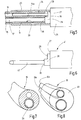
- a cryoprobe 12 is illustrated, which can be used, for example, for the cryotreatment of biological tissue.
- the cryoprobe 12 can be used in a bronchoscope to remove a tissue sample.
- the cryoprobe 12 is introduced, for example, by means of a flexible bronchoscope into the lungs, for example into the pleura, where the head 13 is then brought into contact with biological tissue.
- At least a section of the head 13 is then cooled to such an extent that the adjacent biological tissue freezes and, if tissue removal is desired, adheres to the head 13 and can be taken from the pleura together with this.
- an expanding or evaporating, ie gaseous or liquid cryofluid such as N 2 or CO 2
- a hose arrangement 14 belongs to the tissue probe 12, which in the present exemplary embodiment is formed by a flexible plastic hose 15 which has a first channel 16 and a second channel 17. Both channels 16, 17 can have different diameters.
- the cross section of the second channel 17 is preferably 1.1 to 2.5 times larger than the cross section of the first channel 16. Both channels 16, 17 preferably extend parallel to one another and at a distance from one another through the entire length of the plastic tube 15 and both open the distal, preferably flat end face 18 of the same.
- the plastic tube 15 has a tube end 19 which carries the head 13 of the cryoprobe 12.
- the head 13 comprises a sleeve 20 which is held on the hose end 19 and projects beyond the end face 18.
- the sleeve 20 carries an end cap 21 which is connected to the sleeve in a fluid-tight manner.
- the end cap 21 is preferably welded to the distal end of the sleeve 20, for example in the case of an annular laser weld seam or some other weld seam.
- the end cap 21 thus delimits an expansion space 23 distally for the cryofluid, which is brought in via the first channel 16 and introduced into the expansion space 23 via a nozzle 24.
- the nozzle is a component that can consist of metal, ceramic or a plastic, the plastic preferably being a plastic different from the material of the plastic hose.
- the nozzle 24 is held with its nozzle shaft 24a in the end section of the first channel 16 adjoining the distal end face 18, for example clamped.
- the nozzle 24 can terminate at the end with the distal end face 18 or, as is preferred and in Figure 2 is shown, protrude somewhat out of the channel 16 into the expansion space 23.
- the axial position of the nozzle influences the flow conditions in the expansion chamber 23 and is therefore essential for correct functioning.
- the nozzle 24 preferably has an essentially round nozzle opening which is arranged centrally in the nozzle 24 and thus centrically to the channel in which the nozzle is held. This simplifies manufacture because the nozzle does not need to be aligned before it is pushed into the channel 16. However, an asymmetrical arrangement is also possible, which can benefit the cold distribution.
- the production of the cryoprobe 12 described so far is at least partially in FIG Figure 3 illustrated.
- the plastic tube 15 is first provided with the nozzle 24, which is introduced into the channel 16 at least to the extent that it is temporarily held therein.
- the sleeve 20 is placed on an assembly mandrel 25 which has a sleeve receptacle 26 for this purpose.
- This comprises an annular, preferably flat pressure surface 27 which surrounds a projection 28.
- This projection 28 has, for example, a cylindrical outer circumferential surface, the outer diameter of which corresponds to the inner diameter of the sleeve 20, so that the sleeve 20 can be slipped onto the projection 28 and then onto it is held.
- the projection 28 and the pressure surface 27 together form a seat for the sleeve 20.
- the projection 28 is preferably stepped on its end face. It has a first contact surface 29 for the nozzle 24 and a second contact surface 30, which is intended to come into contact with the distal end face 18 of the plastic tube 15 in the region of the second channel 17 during assembly.
- the assembly of the sleeve 20 and the nozzle 24 on the hose end 19 of the plastic hose 15 results from Figure 5 .
- the plastic hose 15, into which the nozzle 24 with its nozzle shaft 24a is partially inserted, and the assembly mandrel 25 provided with the sleeve 20 are moved axially towards one another in such a way that the hose end 19 first moves into the sleeve 20 and the first contact surface 29 with the End face of the nozzle 24 comes into contact.
- the axial movement is then continued until the second contact surface 30 of the projection 28 comes into contact with the distal end surface 18 of the plastic tube 15.
- the sleeve 20 and the nozzle 24 have well-defined axial positions in relation to the distal end face 18, thus creating an essential basis for the subsequent correct functioning of the cryoprobe 12.
- the joining process described so far can be used both in a first embodiment, in which the sleeve 20 has a smaller diameter than the outer diameter of the plastic tube 15, and in a second embodiment, in which the inner diameter of the sleeve 20 is at least as large as the outer diameter of the plastic hose 15.
- the sleeve 20 can have a funnel-like insertion bevel (not illustrated further) at its proximal end.
- the distal end face 18 of the plastic tube 15 can merge at its radially outer edge into a conical surface which forms an insertion bevel on the tube side. It is possible to secure the sleeve 20 in a press fit on the hose end 19 and the nozzle 24 in a press fit in the hose end 19.
- the sleeve 20 is subsequently deformed radially inwards at least in places and thus narrowed.
- Figure 2 illustrates such a sleeve 20 with two axially spaced apart, in each case annular, pressing zones 31, 32 which encircle the entire circumference of the sleeve 20 and which have been achieved by plastic deformation of the sleeve.
- the plastic deformation can be formed by two or more clamping jaws that hold the sleeve 20 between each other and move radially inward during the pressing process, by a roller burnishing tool with a roller that encircles the circumference of the compression sleeve 20 one or more times or with several such rollers.
- the sleeve can be narrowed in zones or as a whole by magnet deformation by means of a pulsed magnetic field, ie it can be deformed radially inward. In principle, no mechanical contact with the workpiece is required, so that surface contamination of the sleeve can be excluded.
- the process can be used under clean room conditions.
- a suitable connecting means for example an adhesive
- an adhesive on the hose end 19.
- a suitable connecting means for example an adhesive
- the hose end 19 can be pretreated to improve adhesion. For example, this can be done mechanically by fluorination, etching Treatment, for example roughening, plasma activation or by means of a primer.
- adhesives are preferably not used.
- the nozzle 24 (i.e. in particular the nozzle shaft 24a) is also held in a press fit according to the invention.
- the nozzle 24 can have a slightly larger outer diameter than the first lumen 16 in which it is held.
- the press fit can also take place through an at least zone-wise narrowing of the lumen 16 as a result of the pressure exerted on the hose end 19 by the sleeve 20 in a radially inward direction.
- the end cap 21 is attached. To facilitate positioning, this can be one ring-shaped or several e.g. have three finger-shaped or shaped like tabs protrusions that grip into the part of the sleeve 20 protruding beyond the distal end face 18.
- the extension can also be designed as a ring extension with one or more interruptions.
- the end cap 21, which is initially attached, can then be connected to the sleeve 20 in a fluid-tight manner using a suitable joining or welding process, for example laser welding.
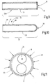
- Figure 11 illustrates the formation of the pressing zone 32 in dashed form.
- the depth of the pressing zone 32 can vary around the circumference of the sleeve 20.
- the depth of the pressing zone 32 in the immediate vicinity of the channels 16, 17 can be reduced compared to the rest of the depth of the pressing zone 32 in order to keep deformation, in particular a narrowing of the channels 16, 17 within limits. It is also possible to reduce the depth of the pressing zone 32 only in the area of the second channel 17 in order to prevent a collapse of the second channel 17, while the pressing action on the first channel 16 promotes the securing of the nozzle 24 in the first channel 16.
- Figure 9 illustrates a nozzle 24 which has a smooth-walled pipe section 33 which is closed at one end by a nozzle plate 34 which has at least one nozzle opening 36.
- the nozzle plate 34 can be welded to the pipe section 33, for example by laser welding.
- the constriction can take place coaxially or asymmetrically with respect to the pipe section 33, for example eccentrically or with an axis oriented obliquely to the axial direction of the pipe section 33.
- the structures for axially securing the nozzle in the lumen 16 can be formed by projections, for example ring-shaped tooth ribs 36, 37, 38, by one or more ribs, knobs, irregular structures such as roughness or knurling .
- the first channel 16 is used for the fluid inflow, that is to say to feed the nozzle 24 with liquid or gaseous cryofluid.
- the second channel 17 serves to discharge the cryofluid from the expansion space 23.
- a support structure 39 in the hose end 19 or along the entire channel 17 to be provided.
- the support structure 39 there consists of a plastic lining of the second channel 17, as it is made of Figure 7 emerges.
- the support structure 39 can consist of one comparatively stiffer plastic or a metal mesh. If the support structure is limited to the hose end 19, it can also consist of a metal tube.
- the hose assembly 14 can, as in Figure 8 can also be formed from several, for example two, plastic tubes 15, 15b, which have the same or different diameters and are preferably embedded in a plastic body 40 in the area of the head. This then forms the hose end 19, otherwise the previous description applies accordingly.
- the manufacture in particular the joining of the hose end 19 with the nozzle 24 and the sleeve 20, takes place according to the invention with an assembly mandrel 41 Figure 4 and 6th .
- a support mandrel 42 is arranged on the second contact surface 30, the outer diameter of which essentially corresponds to the inner diameter of the second channel 17 or is slightly smaller than this.
- the support mandrel 41 moves into the second channel 17 and remains in the channel 17, especially during the radially inward deformation of the sleeve 20.
- the support mandrel 42 prevents the channel 17 from being damaged as a result of the radially inward deformation of the Sleeve 20 is collapsed or narrowed too much.
- the support mandrel 42 can serve to accommodate a thin-walled tube which abuts the frontal contact with the second contact surface 30 and is pushed into the second channel 17 during the joining process to prevent the second channel 17 from collapsing there during the radially inward deformation of the sleeve 20 to prevent. It is also possible to form the projection 28 without a step, the contact surface 29 being formed in a recess in the contact surface 30. The recess, the bottom of which is formed by the contact surface 29, then serves to accommodate the distal end of the nozzle 24, which is then pushed into the first lumen 16 during the joining process. The depth of the recess in turn determines the protrusion of the nozzle 24 over the distal end face 18 in the fully assembled state.
- the recess can be round to accommodate cylindrical, rotationally symmetrical nozzles. If the nozzles are not rotationally symmetrical, for example because the nozzle opening is designed to be eccentric or radiate obliquely, the nozzle can have an anti-rotation structure and for this purpose, for example, have a nose or a recess or be non-circular in some other suitable way. The depression is then correspondingly out of round.
- the inventive method for producing a cryoprobe uses an assembly mandrel 25 for receiving a sleeve 20, which is to form part of the head 13 of the cryoprobe and has three axially offset contact surfaces 27, 29, 30, which after assembly of the sleeve 20 and the nozzle 24 at the hose end 19 ensure the correct axial positioning, in particular the nozzle 24 and the sleeve 20 in relation to the distal end surface 18 of the hose end 19. This ensures the position of the nozzle 24 in the expansion chamber 23 generated after the sleeve 20 has been closed, and thus the functioning of the cryoprobe.
Landscapes
- Health & Medical Sciences (AREA)
- Surgery (AREA)
- Life Sciences & Earth Sciences (AREA)
- Nuclear Medicine, Radiotherapy & Molecular Imaging (AREA)
- Engineering & Computer Science (AREA)
- Veterinary Medicine (AREA)
- Medical Informatics (AREA)
- Molecular Biology (AREA)
- Heart & Thoracic Surgery (AREA)
- Animal Behavior & Ethology (AREA)
- General Health & Medical Sciences (AREA)
- Public Health (AREA)
- Biomedical Technology (AREA)
- Otolaryngology (AREA)
- Pathology (AREA)
- Mechanical Engineering (AREA)
- Surgical Instruments (AREA)
- Endoscopes (AREA)
- Lining Or Joining Of Plastics Or The Like (AREA)
- Quick-Acting Or Multi-Walled Pipe Joints (AREA)
- Joints Allowing Movement (AREA)
- Compressors, Vaccum Pumps And Other Relevant Systems (AREA)
- Pistons, Piston Rings, And Cylinders (AREA)
- Prostheses (AREA)
Priority Applications (8)
| Application Number | Priority Date | Filing Date | Title |
|---|---|---|---|
| PL16199575T PL3323366T3 (pl) | 2016-11-18 | 2016-11-18 | Kriosonda i sposób jej wytwarzania |
| EP16199575.8A EP3323366B1 (de) | 2016-11-18 | 2016-11-18 | Kryosonde und verfahren zur herstellung einer solchen |
| BR102017024072-0A BR102017024072B1 (pt) | 2016-11-18 | 2017-11-09 | Criossonda |
| KR1020170149784A KR102409530B1 (ko) | 2016-11-18 | 2017-11-10 | 냉동 프로브 및 그 제조 방법 |
| JP2017218935A JP7016242B2 (ja) | 2016-11-18 | 2017-11-14 | 凍結プローブおよびその製造方法 |
| RU2017140077A RU2749868C2 (ru) | 2016-11-18 | 2017-11-17 | Криозонд и способ его изготовления |
| US15/816,720 US11076905B2 (en) | 2016-11-18 | 2017-11-17 | Cryoprobe and method of manufacturing the same |
| CN201711146249.3A CN108066002B (zh) | 2016-11-18 | 2017-11-17 | 冷冻探针以及制造冷冻探针的方法 |
Applications Claiming Priority (1)
| Application Number | Priority Date | Filing Date | Title |
|---|---|---|---|
| EP16199575.8A EP3323366B1 (de) | 2016-11-18 | 2016-11-18 | Kryosonde und verfahren zur herstellung einer solchen |
Publications (2)
| Publication Number | Publication Date |
|---|---|
| EP3323366A1 EP3323366A1 (de) | 2018-05-23 |
| EP3323366B1 true EP3323366B1 (de) | 2020-09-30 |
Family
ID=57354217
Family Applications (1)
| Application Number | Title | Priority Date | Filing Date |
|---|---|---|---|
| EP16199575.8A Active EP3323366B1 (de) | 2016-11-18 | 2016-11-18 | Kryosonde und verfahren zur herstellung einer solchen |
Country Status (8)
| Country | Link |
|---|---|
| US (1) | US11076905B2 (pl) |
| EP (1) | EP3323366B1 (pl) |
| JP (1) | JP7016242B2 (pl) |
| KR (1) | KR102409530B1 (pl) |
| CN (1) | CN108066002B (pl) |
| BR (1) | BR102017024072B1 (pl) |
| PL (1) | PL3323366T3 (pl) |
| RU (1) | RU2749868C2 (pl) |
Families Citing this family (6)
| Publication number | Priority date | Publication date | Assignee | Title |
|---|---|---|---|---|
| EP3597112A1 (de) * | 2018-07-17 | 2020-01-22 | Erbe Elektromedizin GmbH | Biopsatbergeeinrichtung |
| EP3769706A1 (de) | 2019-07-23 | 2021-01-27 | Erbe Elektromedizin GmbH | Kryosonde |
| CN111388081B (zh) * | 2020-04-17 | 2024-07-09 | 上海导向医疗系统有限公司 | 冷冻探针结构的锁紧装置与冷冻治疗设备 |
| EP4349288A1 (de) | 2022-10-07 | 2024-04-10 | Erbe Elektromedizin GmbH | Ablationssonde mit innerer kühlung |
| WO2024259414A1 (en) * | 2023-06-16 | 2024-12-19 | Atricure, Inc. | Cryogenic surgical instrument with right angle end effector |
| KR102660309B1 (ko) * | 2023-10-16 | 2024-04-23 | 박성덕 | 용종 제거장치용 체내삽입형 이중튜브의 제조방법 |
Citations (1)
| Publication number | Priority date | Publication date | Assignee | Title |
|---|---|---|---|---|
| US20090287202A1 (en) * | 2008-05-15 | 2009-11-19 | Boston Scientific Scimed, Inc. | Apparatus and methods for cryogenically ablating tissue and adjusting cryogenic ablation regions |
Family Cites Families (11)
| Publication number | Priority date | Publication date | Assignee | Title |
|---|---|---|---|---|
| US5857997A (en) * | 1994-11-14 | 1999-01-12 | Heart Rhythm Technologies, Inc. | Catheter for electrophysiological procedures |
| US5573532A (en) * | 1995-01-13 | 1996-11-12 | Cryomedical Sciences, Inc. | Cryogenic surgical instrument and method of manufacturing the same |
| US7220257B1 (en) * | 2000-07-25 | 2007-05-22 | Scimed Life Systems, Inc. | Cryotreatment device and method |
| US6241722B1 (en) * | 1998-06-17 | 2001-06-05 | Cryogen, Inc. | Cryogenic device, system and method of using same |
| US20070179575A1 (en) * | 2005-07-21 | 2007-08-02 | Esch Brady D | Thermal therapeutic catheter with location detection enhancement |
| DE102008026635B4 (de) | 2007-06-26 | 2010-10-28 | Erbe Elektromedizin Gmbh | Kryobiopsiesonde |
| DE102009018291A1 (de) | 2009-04-21 | 2010-10-28 | Erbe Elektromedizin Gmbh | Kryochirurgisches Instrument |
| DE102009052208A1 (de) * | 2009-09-24 | 2011-04-07 | Erbe Elektromedizin Gmbh | Schlauchverbinder für ein Hochfrequenz-Chirurgiegerät, Handgriff für HF-Chirurgiegerät und Verfahren zum Verbinden von Schläuchen für ein HF-Chirurgiegerät mit einem derartigen Schlauchverbinder |
| DE102010016291A1 (de) * | 2010-04-01 | 2011-10-06 | Erbe Elektromedizin Gmbh | Chirurgisches Instrument, insbesondere elektrochirurgisches Instrument |
| EP2608837B1 (en) | 2010-08-26 | 2016-05-04 | Cryomedix, LLC | Cryoablation balloon catheter |
| US9095320B2 (en) * | 2010-09-27 | 2015-08-04 | CyroMedix, LLC | Cryo-induced renal neuromodulation devices and methods |
-
2016
- 2016-11-18 PL PL16199575T patent/PL3323366T3/pl unknown
- 2016-11-18 EP EP16199575.8A patent/EP3323366B1/de active Active
-
2017
- 2017-11-09 BR BR102017024072-0A patent/BR102017024072B1/pt active IP Right Grant
- 2017-11-10 KR KR1020170149784A patent/KR102409530B1/ko active Active
- 2017-11-14 JP JP2017218935A patent/JP7016242B2/ja active Active
- 2017-11-17 CN CN201711146249.3A patent/CN108066002B/zh active Active
- 2017-11-17 US US15/816,720 patent/US11076905B2/en active Active
- 2017-11-17 RU RU2017140077A patent/RU2749868C2/ru active
Patent Citations (1)
| Publication number | Priority date | Publication date | Assignee | Title |
|---|---|---|---|---|
| US20090287202A1 (en) * | 2008-05-15 | 2009-11-19 | Boston Scientific Scimed, Inc. | Apparatus and methods for cryogenically ablating tissue and adjusting cryogenic ablation regions |
Also Published As
| Publication number | Publication date |
|---|---|
| BR102017024072A2 (pt) | 2018-06-12 |
| CN108066002A (zh) | 2018-05-25 |
| RU2017140077A (ru) | 2019-05-17 |
| US11076905B2 (en) | 2021-08-03 |
| RU2017140077A3 (pl) | 2020-09-08 |
| PL3323366T3 (pl) | 2021-01-25 |
| US20180140342A1 (en) | 2018-05-24 |
| JP7016242B2 (ja) | 2022-02-04 |
| RU2749868C2 (ru) | 2021-06-17 |
| KR102409530B1 (ko) | 2022-06-17 |
| KR20180056379A (ko) | 2018-05-28 |
| JP2018108347A (ja) | 2018-07-12 |
| EP3323366A1 (de) | 2018-05-23 |
| CN108066002B (zh) | 2021-07-06 |
| BR102017024072B1 (pt) | 2023-04-11 |
Similar Documents
| Publication | Publication Date | Title |
|---|---|---|
| EP3323366B1 (de) | Kryosonde und verfahren zur herstellung einer solchen | |
| DE102012110991B4 (de) | Steckereinheit und Verbindungssystem zum Verbinden von Kapillaren, insbesondere für die Hochleistungsflüssigkeitschromatographie | |
| DE10103218B4 (de) | Schnell zerlegbare Düsenanordnung | |
| EP1516142A1 (de) | Vorrichtung zum verbinden von einer aus flexiblem material bestehenden kanüle mit einem rohr | |
| DE60116131T2 (de) | Dichtungsanordnung | |
| DE2830690C2 (de) | Verfahren zur mechanischen Herstellung einer leckdichten Rohrverbindung | |
| WO2013113509A1 (de) | Expansionskopf für aufweitwerkzeuge, diesen umfassendes expansionswerkzeug sowie deren verwendung | |
| EP2153917A2 (de) | Aufweitwerkzeug für Rohre und Rohrpresskupplung | |
| EP3103559A1 (de) | Verfahren zum befestigen eines nietelements und entsprechendes befestigungssystem hierfür | |
| DE102014000624B4 (de) | Verfahren zum Fügen von zumindest zwei zumindest in einer Fügezone überlappend angeordneten Fügeteilen unter Verwendung eines Fügelements | |
| DE69504780T2 (de) | Nietnägel, sowie anwendungsverfahren | |
| EP2028377B1 (de) | Membranantrieb und Verfahren zum Herstellen eines Membranantriebs | |
| EP2683318B1 (de) | Sonotrode für die einbringung von ultraschall-energie | |
| EP3597113A1 (de) | Biopsatbergeeinrichtung | |
| EP1519801A1 (de) | VERFAHREN UND VORRICHTUNG ZUR BEFESTIGUNG VON BAUTEILEN AN UMFÄNGLICH GESCHLOSSENEN HOHLPROFILEN | |
| DE10321309B4 (de) | Vorrichtung zum Verbinden von einer aus flexiblem Material bestehenden Kanüle mit einem Rohr | |
| WO2002026141A1 (de) | Vorrichtung zur verbindung chirurgischer räum- oder bohrwerkzeug-bestandteilen | |
| EP3180543B1 (de) | Schwingungselement mit entkoppeltem bauteil | |
| WO1998006518A1 (de) | Vorrichtung und verfahren zum verbinden eines ersten rohres mit einem rohrförmigen element sowie verbindung zwischen einem ersten rohr und einem rohrförmigen element | |
| EP4236877B1 (de) | Prothesenanker | |
| EP2682253B1 (de) | Aufweitwerkzeug und Werkzeug für Installationsrohre | |
| WO2012031671A1 (de) | Verfahren zum einbringen einer hülse, insbesondere einer gewindehülse in ein werkstück | |
| DE102007049514A1 (de) | Ultraschall-Handstück | |
| DE112016006869T5 (de) | Injektionsnadel für ein Endoskop | |
| AT525084B1 (de) | Rohrpresskupplung |
Legal Events
| Date | Code | Title | Description |
|---|---|---|---|
| PUAI | Public reference made under article 153(3) epc to a published international application that has entered the european phase |
Free format text: ORIGINAL CODE: 0009012 |
|
| STAA | Information on the status of an ep patent application or granted ep patent |
Free format text: STATUS: THE APPLICATION HAS BEEN PUBLISHED |
|
| AK | Designated contracting states |
Kind code of ref document: A1 Designated state(s): AL AT BE BG CH CY CZ DE DK EE ES FI FR GB GR HR HU IE IS IT LI LT LU LV MC MK MT NL NO PL PT RO RS SE SI SK SM TR |
|
| AX | Request for extension of the european patent |
Extension state: BA ME |
|
| STAA | Information on the status of an ep patent application or granted ep patent |
Free format text: STATUS: REQUEST FOR EXAMINATION WAS MADE |
|
| 17P | Request for examination filed |
Effective date: 20180927 |
|
| RBV | Designated contracting states (corrected) |
Designated state(s): AL AT BE BG CH CY CZ DE DK EE ES FI FR GB GR HR HU IE IS IT LI LT LU LV MC MK MT NL NO PL PT RO RS SE SI SK SM TR |
|
| STAA | Information on the status of an ep patent application or granted ep patent |
Free format text: STATUS: EXAMINATION IS IN PROGRESS |
|
| 17Q | First examination report despatched |
Effective date: 20191023 |
|
| GRAP | Despatch of communication of intention to grant a patent |
Free format text: ORIGINAL CODE: EPIDOSNIGR1 |
|
| STAA | Information on the status of an ep patent application or granted ep patent |
Free format text: STATUS: GRANT OF PATENT IS INTENDED |
|
| INTG | Intention to grant announced |
Effective date: 20200525 |
|
| GRAS | Grant fee paid |
Free format text: ORIGINAL CODE: EPIDOSNIGR3 |
|
| GRAA | (expected) grant |
Free format text: ORIGINAL CODE: 0009210 |
|
| STAA | Information on the status of an ep patent application or granted ep patent |
Free format text: STATUS: THE PATENT HAS BEEN GRANTED |
|
| AK | Designated contracting states |
Kind code of ref document: B1 Designated state(s): AL AT BE BG CH CY CZ DE DK EE ES FI FR GB GR HR HU IE IS IT LI LT LU LV MC MK MT NL NO PL PT RO RS SE SI SK SM TR |
|
| REG | Reference to a national code |
Ref country code: CH Ref legal event code: EP Ref country code: GB Ref legal event code: FG4D Free format text: NOT ENGLISH |
|
| REG | Reference to a national code |
Ref country code: AT Ref legal event code: REF Ref document number: 1317962 Country of ref document: AT Kind code of ref document: T Effective date: 20201015 |
|
| REG | Reference to a national code |
Ref country code: DE Ref legal event code: R096 Ref document number: 502016011302 Country of ref document: DE |
|
| REG | Reference to a national code |
Ref country code: IE Ref legal event code: FG4D Free format text: LANGUAGE OF EP DOCUMENT: GERMAN |
|
| PG25 | Lapsed in a contracting state [announced via postgrant information from national office to epo] |
Ref country code: SE Free format text: LAPSE BECAUSE OF FAILURE TO SUBMIT A TRANSLATION OF THE DESCRIPTION OR TO PAY THE FEE WITHIN THE PRESCRIBED TIME-LIMIT Effective date: 20200930 Ref country code: NO Free format text: LAPSE BECAUSE OF FAILURE TO SUBMIT A TRANSLATION OF THE DESCRIPTION OR TO PAY THE FEE WITHIN THE PRESCRIBED TIME-LIMIT Effective date: 20201230 Ref country code: FI Free format text: LAPSE BECAUSE OF FAILURE TO SUBMIT A TRANSLATION OF THE DESCRIPTION OR TO PAY THE FEE WITHIN THE PRESCRIBED TIME-LIMIT Effective date: 20200930 Ref country code: GR Free format text: LAPSE BECAUSE OF FAILURE TO SUBMIT A TRANSLATION OF THE DESCRIPTION OR TO PAY THE FEE WITHIN THE PRESCRIBED TIME-LIMIT Effective date: 20201231 Ref country code: HR Free format text: LAPSE BECAUSE OF FAILURE TO SUBMIT A TRANSLATION OF THE DESCRIPTION OR TO PAY THE FEE WITHIN THE PRESCRIBED TIME-LIMIT Effective date: 20200930 Ref country code: BG Free format text: LAPSE BECAUSE OF FAILURE TO SUBMIT A TRANSLATION OF THE DESCRIPTION OR TO PAY THE FEE WITHIN THE PRESCRIBED TIME-LIMIT Effective date: 20201230 |
|
| PG25 | Lapsed in a contracting state [announced via postgrant information from national office to epo] |
Ref country code: RS Free format text: LAPSE BECAUSE OF FAILURE TO SUBMIT A TRANSLATION OF THE DESCRIPTION OR TO PAY THE FEE WITHIN THE PRESCRIBED TIME-LIMIT Effective date: 20200930 Ref country code: LV Free format text: LAPSE BECAUSE OF FAILURE TO SUBMIT A TRANSLATION OF THE DESCRIPTION OR TO PAY THE FEE WITHIN THE PRESCRIBED TIME-LIMIT Effective date: 20200930 |
|
| REG | Reference to a national code |
Ref country code: NL Ref legal event code: MP Effective date: 20200930 |
|
| REG | Reference to a national code |
Ref country code: LT Ref legal event code: MG4D |
|
| PG25 | Lapsed in a contracting state [announced via postgrant information from national office to epo] |
Ref country code: EE Free format text: LAPSE BECAUSE OF FAILURE TO SUBMIT A TRANSLATION OF THE DESCRIPTION OR TO PAY THE FEE WITHIN THE PRESCRIBED TIME-LIMIT Effective date: 20200930 Ref country code: PT Free format text: LAPSE BECAUSE OF FAILURE TO SUBMIT A TRANSLATION OF THE DESCRIPTION OR TO PAY THE FEE WITHIN THE PRESCRIBED TIME-LIMIT Effective date: 20210201 Ref country code: RO Free format text: LAPSE BECAUSE OF FAILURE TO SUBMIT A TRANSLATION OF THE DESCRIPTION OR TO PAY THE FEE WITHIN THE PRESCRIBED TIME-LIMIT Effective date: 20200930 Ref country code: SM Free format text: LAPSE BECAUSE OF FAILURE TO SUBMIT A TRANSLATION OF THE DESCRIPTION OR TO PAY THE FEE WITHIN THE PRESCRIBED TIME-LIMIT Effective date: 20200930 Ref country code: CZ Free format text: LAPSE BECAUSE OF FAILURE TO SUBMIT A TRANSLATION OF THE DESCRIPTION OR TO PAY THE FEE WITHIN THE PRESCRIBED TIME-LIMIT Effective date: 20200930 Ref country code: LT Free format text: LAPSE BECAUSE OF FAILURE TO SUBMIT A TRANSLATION OF THE DESCRIPTION OR TO PAY THE FEE WITHIN THE PRESCRIBED TIME-LIMIT Effective date: 20200930 |
|
| PG25 | Lapsed in a contracting state [announced via postgrant information from national office to epo] |
Ref country code: AL Free format text: LAPSE BECAUSE OF FAILURE TO SUBMIT A TRANSLATION OF THE DESCRIPTION OR TO PAY THE FEE WITHIN THE PRESCRIBED TIME-LIMIT Effective date: 20200930 Ref country code: ES Free format text: LAPSE BECAUSE OF FAILURE TO SUBMIT A TRANSLATION OF THE DESCRIPTION OR TO PAY THE FEE WITHIN THE PRESCRIBED TIME-LIMIT Effective date: 20200930 Ref country code: IS Free format text: LAPSE BECAUSE OF FAILURE TO SUBMIT A TRANSLATION OF THE DESCRIPTION OR TO PAY THE FEE WITHIN THE PRESCRIBED TIME-LIMIT Effective date: 20210130 |
|
| PG25 | Lapsed in a contracting state [announced via postgrant information from national office to epo] |
Ref country code: SK Free format text: LAPSE BECAUSE OF FAILURE TO SUBMIT A TRANSLATION OF THE DESCRIPTION OR TO PAY THE FEE WITHIN THE PRESCRIBED TIME-LIMIT Effective date: 20200930 Ref country code: MC Free format text: LAPSE BECAUSE OF FAILURE TO SUBMIT A TRANSLATION OF THE DESCRIPTION OR TO PAY THE FEE WITHIN THE PRESCRIBED TIME-LIMIT Effective date: 20200930 Ref country code: NL Free format text: LAPSE BECAUSE OF FAILURE TO SUBMIT A TRANSLATION OF THE DESCRIPTION OR TO PAY THE FEE WITHIN THE PRESCRIBED TIME-LIMIT Effective date: 20200930 |
|
| REG | Reference to a national code |
Ref country code: CH Ref legal event code: PL |
|
| REG | Reference to a national code |
Ref country code: DE Ref legal event code: R097 Ref document number: 502016011302 Country of ref document: DE |
|
| PG25 | Lapsed in a contracting state [announced via postgrant information from national office to epo] |
Ref country code: LU Free format text: LAPSE BECAUSE OF NON-PAYMENT OF DUE FEES Effective date: 20201118 |
|
| PLBE | No opposition filed within time limit |
Free format text: ORIGINAL CODE: 0009261 |
|
| STAA | Information on the status of an ep patent application or granted ep patent |
Free format text: STATUS: NO OPPOSITION FILED WITHIN TIME LIMIT |
|
| REG | Reference to a national code |
Ref country code: BE Ref legal event code: MM Effective date: 20201130 |
|
| PG25 | Lapsed in a contracting state [announced via postgrant information from national office to epo] |
Ref country code: DK Free format text: LAPSE BECAUSE OF FAILURE TO SUBMIT A TRANSLATION OF THE DESCRIPTION OR TO PAY THE FEE WITHIN THE PRESCRIBED TIME-LIMIT Effective date: 20200930 Ref country code: CH Free format text: LAPSE BECAUSE OF NON-PAYMENT OF DUE FEES Effective date: 20201130 Ref country code: LI Free format text: LAPSE BECAUSE OF NON-PAYMENT OF DUE FEES Effective date: 20201130 |
|
| 26N | No opposition filed |
Effective date: 20210701 |
|
| PG25 | Lapsed in a contracting state [announced via postgrant information from national office to epo] |
Ref country code: IE Free format text: LAPSE BECAUSE OF NON-PAYMENT OF DUE FEES Effective date: 20201118 |
|
| PG25 | Lapsed in a contracting state [announced via postgrant information from national office to epo] |
Ref country code: SI Free format text: LAPSE BECAUSE OF FAILURE TO SUBMIT A TRANSLATION OF THE DESCRIPTION OR TO PAY THE FEE WITHIN THE PRESCRIBED TIME-LIMIT Effective date: 20200930 |
|
| PG25 | Lapsed in a contracting state [announced via postgrant information from national office to epo] |
Ref country code: IS Free format text: LAPSE BECAUSE OF FAILURE TO SUBMIT A TRANSLATION OF THE DESCRIPTION OR TO PAY THE FEE WITHIN THE PRESCRIBED TIME-LIMIT Effective date: 20210130 Ref country code: TR Free format text: LAPSE BECAUSE OF FAILURE TO SUBMIT A TRANSLATION OF THE DESCRIPTION OR TO PAY THE FEE WITHIN THE PRESCRIBED TIME-LIMIT Effective date: 20200930 Ref country code: MT Free format text: LAPSE BECAUSE OF FAILURE TO SUBMIT A TRANSLATION OF THE DESCRIPTION OR TO PAY THE FEE WITHIN THE PRESCRIBED TIME-LIMIT Effective date: 20200930 Ref country code: CY Free format text: LAPSE BECAUSE OF FAILURE TO SUBMIT A TRANSLATION OF THE DESCRIPTION OR TO PAY THE FEE WITHIN THE PRESCRIBED TIME-LIMIT Effective date: 20200930 |
|
| PG25 | Lapsed in a contracting state [announced via postgrant information from national office to epo] |
Ref country code: MK Free format text: LAPSE BECAUSE OF FAILURE TO SUBMIT A TRANSLATION OF THE DESCRIPTION OR TO PAY THE FEE WITHIN THE PRESCRIBED TIME-LIMIT Effective date: 20200930 |
|
| PG25 | Lapsed in a contracting state [announced via postgrant information from national office to epo] |
Ref country code: BE Free format text: LAPSE BECAUSE OF NON-PAYMENT OF DUE FEES Effective date: 20201130 |
|
| REG | Reference to a national code |
Ref country code: AT Ref legal event code: MM01 Ref document number: 1317962 Country of ref document: AT Kind code of ref document: T Effective date: 20211118 |
|
| PG25 | Lapsed in a contracting state [announced via postgrant information from national office to epo] |
Ref country code: AT Free format text: LAPSE BECAUSE OF NON-PAYMENT OF DUE FEES Effective date: 20211118 |
|
| PGFP | Annual fee paid to national office [announced via postgrant information from national office to epo] |
Ref country code: DE Payment date: 20241128 Year of fee payment: 9 |
|
| PGFP | Annual fee paid to national office [announced via postgrant information from national office to epo] |
Ref country code: PL Payment date: 20241023 Year of fee payment: 9 |
|
| PGFP | Annual fee paid to national office [announced via postgrant information from national office to epo] |
Ref country code: GB Payment date: 20241126 Year of fee payment: 9 |
|
| PGFP | Annual fee paid to national office [announced via postgrant information from national office to epo] |
Ref country code: FR Payment date: 20241126 Year of fee payment: 9 |
|
| PGFP | Annual fee paid to national office [announced via postgrant information from national office to epo] |
Ref country code: IT Payment date: 20241125 Year of fee payment: 9 |