EP4236877B1 - Prothesenanker - Google Patents
Prothesenanker Download PDFInfo
- Publication number
- EP4236877B1 EP4236877B1 EP21798708.0A EP21798708A EP4236877B1 EP 4236877 B1 EP4236877 B1 EP 4236877B1 EP 21798708 A EP21798708 A EP 21798708A EP 4236877 B1 EP4236877 B1 EP 4236877B1
- Authority
- EP
- European Patent Office
- Prior art keywords
- prosthesis
- wedge
- clamping shaft
- anchor
- clamping
- Prior art date
- Legal status (The legal status is an assumption and is not a legal conclusion. Google has not performed a legal analysis and makes no representation as to the accuracy of the status listed.)
- Active
Links
Images

Classifications
-
- A—HUMAN NECESSITIES
- A61—MEDICAL OR VETERINARY SCIENCE; HYGIENE
- A61F—FILTERS IMPLANTABLE INTO BLOOD VESSELS; PROSTHESES; DEVICES PROVIDING PATENCY TO, OR PREVENTING COLLAPSING OF, TUBULAR STRUCTURES OF THE BODY, e.g. STENTS; ORTHOPAEDIC, NURSING OR CONTRACEPTIVE DEVICES; FOMENTATION; TREATMENT OR PROTECTION OF EYES OR EARS; BANDAGES, DRESSINGS OR ABSORBENT PADS; FIRST-AID KITS
- A61F2/00—Filters implantable into blood vessels; Prostheses, i.e. artificial substitutes or replacements for parts of the body; Appliances for connecting them with the body; Devices providing patency to, or preventing collapsing of, tubular structures of the body, e.g. stents
- A61F2/02—Prostheses implantable into the body
- A61F2/28—Bones
- A61F2/2814—Bone stump caps
-
- A—HUMAN NECESSITIES
- A61—MEDICAL OR VETERINARY SCIENCE; HYGIENE
- A61B—DIAGNOSIS; SURGERY; IDENTIFICATION
- A61B17/00—Surgical instruments, devices or methods
- A61B17/56—Surgical instruments or methods for treatment of bones or joints; Devices specially adapted therefor
- A61B17/58—Surgical instruments or methods for treatment of bones or joints; Devices specially adapted therefor for osteosynthesis, e.g. bone plates, screws or setting implements
- A61B17/68—Internal fixation devices, including fasteners and spinal fixators, even if a part thereof projects from the skin
- A61B17/72—Intramedullary devices, e.g. pins or nails
- A61B17/7233—Intramedullary devices, e.g. pins or nails with special means of locking the nail to the bone
- A61B17/7258—Intramedullary devices, e.g. pins or nails with special means of locking the nail to the bone with laterally expanding parts, e.g. for gripping the bone
-
- A—HUMAN NECESSITIES
- A61—MEDICAL OR VETERINARY SCIENCE; HYGIENE
- A61F—FILTERS IMPLANTABLE INTO BLOOD VESSELS; PROSTHESES; DEVICES PROVIDING PATENCY TO, OR PREVENTING COLLAPSING OF, TUBULAR STRUCTURES OF THE BODY, e.g. STENTS; ORTHOPAEDIC, NURSING OR CONTRACEPTIVE DEVICES; FOMENTATION; TREATMENT OR PROTECTION OF EYES OR EARS; BANDAGES, DRESSINGS OR ABSORBENT PADS; FIRST-AID KITS
- A61F2/00—Filters implantable into blood vessels; Prostheses, i.e. artificial substitutes or replacements for parts of the body; Appliances for connecting them with the body; Devices providing patency to, or preventing collapsing of, tubular structures of the body, e.g. stents
- A61F2/02—Prostheses implantable into the body
- A61F2/30—Joints
- A61F2002/30001—Additional features of subject-matter classified in A61F2/28, A61F2/30 and subgroups thereof
- A61F2002/30108—Shapes
- A61F2002/30199—Three-dimensional shapes
- A61F2002/30224—Three-dimensional shapes cylindrical
- A61F2002/3023—Three-dimensional shapes cylindrical wedge-shaped cylinders
-
- A—HUMAN NECESSITIES
- A61—MEDICAL OR VETERINARY SCIENCE; HYGIENE
- A61F—FILTERS IMPLANTABLE INTO BLOOD VESSELS; PROSTHESES; DEVICES PROVIDING PATENCY TO, OR PREVENTING COLLAPSING OF, TUBULAR STRUCTURES OF THE BODY, e.g. STENTS; ORTHOPAEDIC, NURSING OR CONTRACEPTIVE DEVICES; FOMENTATION; TREATMENT OR PROTECTION OF EYES OR EARS; BANDAGES, DRESSINGS OR ABSORBENT PADS; FIRST-AID KITS
- A61F2/00—Filters implantable into blood vessels; Prostheses, i.e. artificial substitutes or replacements for parts of the body; Appliances for connecting them with the body; Devices providing patency to, or preventing collapsing of, tubular structures of the body, e.g. stents
- A61F2/02—Prostheses implantable into the body
- A61F2/30—Joints
- A61F2002/30001—Additional features of subject-matter classified in A61F2/28, A61F2/30 and subgroups thereof
- A61F2002/30108—Shapes
- A61F2002/30199—Three-dimensional shapes
- A61F2002/30224—Three-dimensional shapes cylindrical
- A61F2002/30235—Three-dimensional shapes cylindrical tubular, e.g. sleeves
- A61F2002/30237—Three-dimensional shapes cylindrical tubular, e.g. sleeves partial tubes
-
- A—HUMAN NECESSITIES
- A61—MEDICAL OR VETERINARY SCIENCE; HYGIENE
- A61F—FILTERS IMPLANTABLE INTO BLOOD VESSELS; PROSTHESES; DEVICES PROVIDING PATENCY TO, OR PREVENTING COLLAPSING OF, TUBULAR STRUCTURES OF THE BODY, e.g. STENTS; ORTHOPAEDIC, NURSING OR CONTRACEPTIVE DEVICES; FOMENTATION; TREATMENT OR PROTECTION OF EYES OR EARS; BANDAGES, DRESSINGS OR ABSORBENT PADS; FIRST-AID KITS
- A61F2/00—Filters implantable into blood vessels; Prostheses, i.e. artificial substitutes or replacements for parts of the body; Appliances for connecting them with the body; Devices providing patency to, or preventing collapsing of, tubular structures of the body, e.g. stents
- A61F2/02—Prostheses implantable into the body
- A61F2/30—Joints
- A61F2002/30001—Additional features of subject-matter classified in A61F2/28, A61F2/30 and subgroups thereof
- A61F2002/30316—The prosthesis having different structural features at different locations within the same prosthesis; Connections between prosthetic parts; Special structural features of bone or joint prostheses not otherwise provided for
- A61F2002/30329—Connections or couplings between prosthetic parts, e.g. between modular parts; Connecting elements
- A61F2002/30331—Connections or couplings between prosthetic parts, e.g. between modular parts; Connecting elements made by longitudinally pushing a protrusion into a complementarily-shaped recess, e.g. held by friction fit
- A61F2002/30362—Connections or couplings between prosthetic parts, e.g. between modular parts; Connecting elements made by longitudinally pushing a protrusion into a complementarily-shaped recess, e.g. held by friction fit with possibility of relative movement between the protrusion and the recess
- A61F2002/30375—Connections or couplings between prosthetic parts, e.g. between modular parts; Connecting elements made by longitudinally pushing a protrusion into a complementarily-shaped recess, e.g. held by friction fit with possibility of relative movement between the protrusion and the recess with an intermediate bushing or sleeve between the moving parts
-
- A—HUMAN NECESSITIES
- A61—MEDICAL OR VETERINARY SCIENCE; HYGIENE
- A61F—FILTERS IMPLANTABLE INTO BLOOD VESSELS; PROSTHESES; DEVICES PROVIDING PATENCY TO, OR PREVENTING COLLAPSING OF, TUBULAR STRUCTURES OF THE BODY, e.g. STENTS; ORTHOPAEDIC, NURSING OR CONTRACEPTIVE DEVICES; FOMENTATION; TREATMENT OR PROTECTION OF EYES OR EARS; BANDAGES, DRESSINGS OR ABSORBENT PADS; FIRST-AID KITS
- A61F2/00—Filters implantable into blood vessels; Prostheses, i.e. artificial substitutes or replacements for parts of the body; Appliances for connecting them with the body; Devices providing patency to, or preventing collapsing of, tubular structures of the body, e.g. stents
- A61F2/02—Prostheses implantable into the body
- A61F2/30—Joints
- A61F2002/30001—Additional features of subject-matter classified in A61F2/28, A61F2/30 and subgroups thereof
- A61F2002/30316—The prosthesis having different structural features at different locations within the same prosthesis; Connections between prosthetic parts; Special structural features of bone or joint prostheses not otherwise provided for
- A61F2002/30329—Connections or couplings between prosthetic parts, e.g. between modular parts; Connecting elements
- A61F2002/30405—Connections or couplings between prosthetic parts, e.g. between modular parts; Connecting elements made by screwing complementary threads machined on the parts themselves
-
- A—HUMAN NECESSITIES
- A61—MEDICAL OR VETERINARY SCIENCE; HYGIENE
- A61F—FILTERS IMPLANTABLE INTO BLOOD VESSELS; PROSTHESES; DEVICES PROVIDING PATENCY TO, OR PREVENTING COLLAPSING OF, TUBULAR STRUCTURES OF THE BODY, e.g. STENTS; ORTHOPAEDIC, NURSING OR CONTRACEPTIVE DEVICES; FOMENTATION; TREATMENT OR PROTECTION OF EYES OR EARS; BANDAGES, DRESSINGS OR ABSORBENT PADS; FIRST-AID KITS
- A61F2/00—Filters implantable into blood vessels; Prostheses, i.e. artificial substitutes or replacements for parts of the body; Appliances for connecting them with the body; Devices providing patency to, or preventing collapsing of, tubular structures of the body, e.g. stents
- A61F2/02—Prostheses implantable into the body
- A61F2/30—Joints
- A61F2002/30001—Additional features of subject-matter classified in A61F2/28, A61F2/30 and subgroups thereof
- A61F2002/30316—The prosthesis having different structural features at different locations within the same prosthesis; Connections between prosthetic parts; Special structural features of bone or joint prostheses not otherwise provided for
- A61F2002/30329—Connections or couplings between prosthetic parts, e.g. between modular parts; Connecting elements
- A61F2002/30433—Connections or couplings between prosthetic parts, e.g. between modular parts; Connecting elements using additional screws, bolts, dowels, rivets or washers e.g. connecting screws
-
- A—HUMAN NECESSITIES
- A61—MEDICAL OR VETERINARY SCIENCE; HYGIENE
- A61F—FILTERS IMPLANTABLE INTO BLOOD VESSELS; PROSTHESES; DEVICES PROVIDING PATENCY TO, OR PREVENTING COLLAPSING OF, TUBULAR STRUCTURES OF THE BODY, e.g. STENTS; ORTHOPAEDIC, NURSING OR CONTRACEPTIVE DEVICES; FOMENTATION; TREATMENT OR PROTECTION OF EYES OR EARS; BANDAGES, DRESSINGS OR ABSORBENT PADS; FIRST-AID KITS
- A61F2/00—Filters implantable into blood vessels; Prostheses, i.e. artificial substitutes or replacements for parts of the body; Appliances for connecting them with the body; Devices providing patency to, or preventing collapsing of, tubular structures of the body, e.g. stents
- A61F2/02—Prostheses implantable into the body
- A61F2/30—Joints
- A61F2002/30001—Additional features of subject-matter classified in A61F2/28, A61F2/30 and subgroups thereof
- A61F2002/30316—The prosthesis having different structural features at different locations within the same prosthesis; Connections between prosthetic parts; Special structural features of bone or joint prostheses not otherwise provided for
- A61F2002/30329—Connections or couplings between prosthetic parts, e.g. between modular parts; Connecting elements
- A61F2002/30476—Connections or couplings between prosthetic parts, e.g. between modular parts; Connecting elements locked by an additional locking mechanism
- A61F2002/30494—Cooperating protrusions and recesses, e.g. radial serrations, located on abutting end surfaces of a longitudinal connection
-
- A—HUMAN NECESSITIES
- A61—MEDICAL OR VETERINARY SCIENCE; HYGIENE
- A61F—FILTERS IMPLANTABLE INTO BLOOD VESSELS; PROSTHESES; DEVICES PROVIDING PATENCY TO, OR PREVENTING COLLAPSING OF, TUBULAR STRUCTURES OF THE BODY, e.g. STENTS; ORTHOPAEDIC, NURSING OR CONTRACEPTIVE DEVICES; FOMENTATION; TREATMENT OR PROTECTION OF EYES OR EARS; BANDAGES, DRESSINGS OR ABSORBENT PADS; FIRST-AID KITS
- A61F2/00—Filters implantable into blood vessels; Prostheses, i.e. artificial substitutes or replacements for parts of the body; Appliances for connecting them with the body; Devices providing patency to, or preventing collapsing of, tubular structures of the body, e.g. stents
- A61F2/02—Prostheses implantable into the body
- A61F2/30—Joints
- A61F2002/30001—Additional features of subject-matter classified in A61F2/28, A61F2/30 and subgroups thereof
- A61F2002/30316—The prosthesis having different structural features at different locations within the same prosthesis; Connections between prosthetic parts; Special structural features of bone or joint prostheses not otherwise provided for
- A61F2002/30329—Connections or couplings between prosthetic parts, e.g. between modular parts; Connecting elements
- A61F2002/30518—Connections or couplings between prosthetic parts, e.g. between modular parts; Connecting elements with possibility of relative movement between the prosthetic parts
-
- A—HUMAN NECESSITIES
- A61—MEDICAL OR VETERINARY SCIENCE; HYGIENE
- A61F—FILTERS IMPLANTABLE INTO BLOOD VESSELS; PROSTHESES; DEVICES PROVIDING PATENCY TO, OR PREVENTING COLLAPSING OF, TUBULAR STRUCTURES OF THE BODY, e.g. STENTS; ORTHOPAEDIC, NURSING OR CONTRACEPTIVE DEVICES; FOMENTATION; TREATMENT OR PROTECTION OF EYES OR EARS; BANDAGES, DRESSINGS OR ABSORBENT PADS; FIRST-AID KITS
- A61F2/00—Filters implantable into blood vessels; Prostheses, i.e. artificial substitutes or replacements for parts of the body; Appliances for connecting them with the body; Devices providing patency to, or preventing collapsing of, tubular structures of the body, e.g. stents
- A61F2/02—Prostheses implantable into the body
- A61F2/30—Joints
- A61F2002/30001—Additional features of subject-matter classified in A61F2/28, A61F2/30 and subgroups thereof
- A61F2002/30316—The prosthesis having different structural features at different locations within the same prosthesis; Connections between prosthetic parts; Special structural features of bone or joint prostheses not otherwise provided for
- A61F2002/30535—Special structural features of bone or joint prostheses not otherwise provided for
- A61F2002/30537—Special structural features of bone or joint prostheses not otherwise provided for adjustable
- A61F2002/30545—Special structural features of bone or joint prostheses not otherwise provided for adjustable for adjusting a diameter
-
- A—HUMAN NECESSITIES
- A61—MEDICAL OR VETERINARY SCIENCE; HYGIENE
- A61F—FILTERS IMPLANTABLE INTO BLOOD VESSELS; PROSTHESES; DEVICES PROVIDING PATENCY TO, OR PREVENTING COLLAPSING OF, TUBULAR STRUCTURES OF THE BODY, e.g. STENTS; ORTHOPAEDIC, NURSING OR CONTRACEPTIVE DEVICES; FOMENTATION; TREATMENT OR PROTECTION OF EYES OR EARS; BANDAGES, DRESSINGS OR ABSORBENT PADS; FIRST-AID KITS
- A61F2/00—Filters implantable into blood vessels; Prostheses, i.e. artificial substitutes or replacements for parts of the body; Appliances for connecting them with the body; Devices providing patency to, or preventing collapsing of, tubular structures of the body, e.g. stents
- A61F2/02—Prostheses implantable into the body
- A61F2/30—Joints
- A61F2002/30001—Additional features of subject-matter classified in A61F2/28, A61F2/30 and subgroups thereof
- A61F2002/30316—The prosthesis having different structural features at different locations within the same prosthesis; Connections between prosthetic parts; Special structural features of bone or joint prostheses not otherwise provided for
- A61F2002/30535—Special structural features of bone or joint prostheses not otherwise provided for
- A61F2002/30579—Special structural features of bone or joint prostheses not otherwise provided for with mechanically expandable devices, e.g. fixation devices
Definitions
- the invention relates to a prosthesis anchor for a prosthesis, in particular an endoprosthesis or exoprosthesis, with a clamping axis having a threaded section for transmitting an axial relative movement between at least one sleeve body according to the preamble of the main claim that can be placed against an inner wall surface of a recess in a bone, in particular a bore or a bone canal, and can be pre-tensioned in the radial direction relative to the clamping axis with respect to the inner wall surface.
- the invention also relates to a prosthesis designed, for example, as a joint prosthesis with such a prosthesis anchor.
- Such a prosthetic anchor is already available from US 5 116 378 A
- a proximal element is provided with a hole whose diameter is slightly larger than the diameter of the clamping axis.
- joint prostheses typically consist of a prosthetic shaft that is anchored in the bone and a joint head that is connected to the prosthetic shaft and replaces the natural joint head, with different materials such as plastic, such as polyethylene, and ceramic being used.
- the known joint prostheses mostly have a prosthetic shaft with nail- or screw-shaped ends that are inserted into the corresponding distal or proximal bone.
- cement-free prostheses are driven firmly into the bone.
- a special rough surface or coating ensures that the prosthesis is firmly in place immediately after insertion and that the bone then gradually bonds with it.
- Cemented prostheses are attached with a special two-component adhesive.
- the EN 603 11 269 T2 refers to a joint prosthesis in which expansion inserts equipped with sleeves are arranged in a respective canal of the bone An expansion element is then screwed onto an internal thread of the sleeve. When screwed in, the expansion element moves axially so that the conical shaft of the expansion element acts on the sleeves, which are elastically deformable in the radial direction by means of grooves and cause an expansion of the frustoconical outer profile of the expansion inserts.
- the EP 0 827 385 B1 refers to a nail for fixing the position and shape of broken long bones.
- the nail When the nail is implanted, its cross-section is reversibly expanded.
- the enlargement body is pressurized from the inside by pumping in a gas or liquid and expanded, resulting in a star-shaped cross-section.
- the DE 103 08 338 A1 refers to a bone dowel that can be inserted into a hole in the bone and into which a screw can be screwed to ensure reliable, permanent anchoring in the bone, for example to fix bone fragments using an osteosynthesis plate.
- the dowel spreads out in such a way that the screw emerges through a slot on one side of the bone dowel and can engage the bone.
- the US 3 846 846 A describes a hip joint head prosthesis with an anchoring part that engages and can be fixed in the bone canal of the thigh with several expansion elements that are spread open using an expansion element. The resulting steps, together with the friction of the expansion surfaces, ensure that the prosthesis is anchored securely and without slipping. Anti-twisting protection between a pull rod and the expansion elements is achieved by profiling the pull rod.
- fixation devices A disadvantage of such fixation devices is that the deformation by a wedge body or by a fluid leads to a relatively even transfer of force to the bone, but the pre-tensioning force acting on the bone can only be adjusted to a very limited extent.
- high loads on the prosthesis shaft can lead to compression of the deforming body, which can then come loose from the cavity.
- fixation can lead to an undesirable change in orientation, in particular to a deflection from its coaxial orientation to the cavity, which is noticeable to the affected patient during use, especially in the case of joint prostheses.
- Bone nails are known that are inserted into holes and expand due to the so-called memory effect when heat is applied using a heater or body heat. Open cross-sections with wave or sawtooth profiles along the nail can be used for better adhesion.
- An intramedullary nail is known in which the nail shaft is designed as a hollow body made of a memory alloy that takes on one of two possible shape states depending on the temperature. This allows the intramedullary nail to be converted in situ from a small-section to an expanded state and vice versa.
- the invention is based on the object of creating a prosthesis anchor which allows a defined introduction of force in the radial direction relative to the inner wall surface and at the same time the maintenance of a predetermined, in particular centered, orientation within the recess. Furthermore, the invention is based on the object of creating a prosthesis, in particular designed as a joint prosthesis, with such a prosthesis anchor.
- the first-mentioned object is achieved according to the invention with a prosthetic anchor according to the features of claim 1.
- the further embodiment of the invention can be found in the subclaims.
- a prosthesis anchor in which the clamping axis is connected to at least one wedge sleeve in a rotationally fixed manner.
- This provides the first possibility of fixing the prosthesis anchor in the correct position in the cavity by means of a defined introduction of force, which also does not require the introduction of pressure fluids or thermal energy.
- the essential idea of the invention is the relative axial displacement of the wedge sleeves, which slide along their inclined surfaces and are therefore deflected radially with the clamping axis in accordance with the annular gap.
- the torque introduced by the clamping body, designed as a sleeve nut for example, for the relative axial displacement of the wedge sleeves can also be used to draw conclusions with sufficient accuracy on the radial force effect of the wedge sleeves in relation to the inner wall surface on the basis of empirical values, so that overloading can be avoided here by limiting the torque and the required holding forces can be achieved without any problems.
- the introduced torque can of course also be monitored and recorded using measurement technology or fed into a data processing system.
- the sliding of the wedge sleeves along their inclined surfaces also leads to a uniform, synchronous radial displacement of the wedge sleeves in the radial direction, without this causing an undesirable displacement or deflection of the clamping axis.
- the position and orientation of the clamping axis does not change during fixation, so that tight tolerances in positioning can be maintained and, in addition to the durability, the functionality of the prosthesis fixed in this way can also be significantly improved.
- the wedge sleeves are displaced parallel to the clamping axis according to the invention and thus lie flat against the inner wall surface. This achieves optimal force transmission, which can be further improved by a suitable surface finish of the wedge sleeves, for example structuring or profiling.
- the wedge sleeves could, for example, have a polygonal cross-sectional shape.
- the wedge sleeves have a rotationally symmetrical, in particular cylindrical basic shape.
- the wedge sleeves are preferably made of a high-quality metal suitable for medical products, although plastics are not fundamentally excluded.
- wedge sleeves made of GRP or CFRP can be made, which can optionally be provided with a metallic position indicator in order to be able to check the position of use using X-ray methods.
- the wedge sleeves can lie directly against each other along their inclined surfaces.
- the prosthesis anchor has at least one guide part arranged between the wedge sleeves and lying against the inclined surfaces of opposite wedge sleeves, which, due to its material properties, for example made of plastic, serves to reduce the frictional forces during the radial displacement of the wedge sleeves and in particular to prevent undesirable material abrasion, which would otherwise occur in the bone.
- the guide part is suitable as a cover element for closing the gaps or slots of the wedge sleeves as well as other recesses on the clamping axis so that the surface is free of undercuts.
- the guide part can also have optimized properties with regard to growing into the bone. Furthermore, the guide part can be exchanged for easy length adjustment.
- At least the section of the prosthetic anchor delimited by the wedge sleeves is enclosed by a flexible, for example tubular, casing body in order to introduce an intermediate layer into the cavity that is favorable for the bone tissue.
- the components of the prosthetic anchor are thereby captively enclosed by the casing body even when not in use.
- the clamping body is fixed in a rotationally fixed manner in the use position relative to the clamping axis by means of a rotation lock.
- the clamping body designed for example as a clamping toggle for manual operation, serves to transfer the axial preload force to the wedge sleeves. In the use position, this is fixed in a rotationally fixed manner in that the rotation lock simultaneously encloses the non-rotationally symmetrical clamping body by means of a positive-locking recess and engages with a projection in a recess in the clamping axis.
- the rotation lock is thus connected to the clamping axis in a rotationally fixed manner.
- the rotation lock is in turn secured by a fixing means acting in the axial direction, for example a screw.
- the clamping axis in the end section has an internal thread for the fixing means in addition to the external thread for the clamping toggle.
- the clamping axis could be permanently or integrally connected to a functional carrier of the prosthesis, for example a joint head.
- a functional carrier of the prosthesis for example a joint head.
- a variant of the invention in which the clamping axis has a shape for a tool holder and/or a functional element of the prosthesis is particularly practical, so that the functional element can be connected to the clamping axis after it has been fixed and can be aligned or adjusted accordingly.
- the clamping axis therefore enables universal use and is not limited to prostheses in the narrower sense, but can also be used, for example, to fix bone plates or other medical aids that have to be separated from the body after healing.
- the clamping axis has a radially expanded pressure plate with the shape for the positive reception of the anti-rotation device.
- the pressure plate serves to support the prosthetic anchor on an edge area surrounding the recess in the bone and thus at the same time as a depth stop for a defined positioning of the prosthetic anchor in the bone.
- the pressure plate preferably has a rotationally symmetrical basic shape and a flat support surface as an abutment for the clamping body.
- At least one of the wedge sleeves is designed to be continuously slotted, in particular in the longitudinal direction, wherein in the position of use at least one radial projection of the clamping axis engages in the slot and connects the wedge sleeve to the clamping axis in a rotationally fixed manner.
- At least one projection of the clamping axis engages in a slot of each of the two wedge sleeves, they are connected to the clamping axis in a rotationally fixed manner relative to the latter.
- At least one of the wedge sleeves has a longitudinally continuous slot with a slot width greater than the diameter of the clamping axis in the cross-sectional plane, so that the wedge sleeves can be placed on the clamping axis transversely to it and can be easily replaced.
- the second task namely to create a prosthesis, particularly designed as a joint prosthesis, with such a prosthesis anchor, is achieved according to the invention in that the sleeve body has at least two wedge sleeves that can be moved relative to one another, which rest against one another or against a guide part enclosed between the wedge sleeves as a contact surface along an inclined surface that is inclined relative to the cross-sectional plane to their longitudinal axis and are simultaneously displaced radially due to a relative axial displacement and approach, insofar as the annular gap between the inner diameter of the wedge sleeves and the enclosed clamping axis allows this.
- the wedge sleeves designed as dimensionally stable hollow bodies, can thus be pressed against the inner wall surface of the bone cavity with a defined pre-tensioning force.
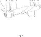
- a prosthesis anchor 1 according to the invention for a prosthesis not shown in detail is described below with reference to Figures 1 to 5 explained in more detail.
- the prosthesis anchor 1 has a clamping axis 2 with a threaded section 3, onto which a clamping body 5 equipped with an internal thread 4 can be screwed.
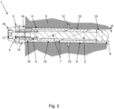
- the resulting axial relative movement causes two wedge sleeves 6, which are equipped with an inclined surface 7 that is inclined relative to the cross-sectional plane of the clamping axis 2, to be displaced radially until they finally come into contact with an inner wall surface 8 of a Figure 2 indicated bone cavity of a bone 9.
- the clamping axis 2 forms a basic element and carries the two slotted wedge sleeves 6.
- a radial projection 10 of the clamping axis 2 engages in a respective slot 11 of the wedge sleeves 6, so that these are connected to the clamping axis 2 in a rotationally fixed manner.
- the wedge sleeves 6 can be clamped manually by means of the clamping body 5 designed as a clamping toggle.
- the wedge sleeves 6 By dimensioning the clear inner diameter of the wedge sleeves 6 slightly larger than the diameter of the clamping axis 2, a relative radial displacement relative to the clamping axis 2 in opposite directions in the direction of arrow 12 transverse to the clamping axis 2 with a distance A is made possible.
- the wedge sleeves 6 are clamped against one another by means of an enclosed guide part 13 and slide along its corresponding surfaces. As a result the wedge sleeves 6 are clamped in the cavity of the bone 9 on opposite surface sections of the inner wall surface 8.
- the guide part 13 arranged between the wedge sleeves 6 serves to center the prosthesis anchor 1 in the cavity of the bone 9.
- the clamping body 5 lies axially against an end face of a pressure plate 14 designed as a flange or collar.
- the pressure plate 14 also serves as a base for the particularly form-fitting and/or force-fitting fixation of functional elements of the prosthesis by means of a formation 15 for a tool holder and a functional element of the prosthesis.
- the use position thus set is secured by an anti-twist device 16, which connects the pressure plate 14 and the clamping body 5 in the use position in a rotationally fixed manner and thus prevents an unintentional release of the connection, as shown in Figure 5 shown.
- the anti-twisting device 16 is in turn secured by a fixing means 17 designed as a screw acting in the axial direction, in that the fixing means 17 is screwed into the internal thread 4 in the end section of the clamping axis 2.
Landscapes
- Health & Medical Sciences (AREA)
- Orthopedic Medicine & Surgery (AREA)
- Cardiology (AREA)
- Oral & Maxillofacial Surgery (AREA)
- Transplantation (AREA)
- Engineering & Computer Science (AREA)
- Biomedical Technology (AREA)
- Heart & Thoracic Surgery (AREA)
- Vascular Medicine (AREA)
- Life Sciences & Earth Sciences (AREA)
- Animal Behavior & Ethology (AREA)
- General Health & Medical Sciences (AREA)
- Public Health (AREA)
- Veterinary Medicine (AREA)
- Prostheses (AREA)
Description
- Die Erfindung betrifft einen Prothesenanker für eine Prothese, insbesondere eine Endo- oder Exoprothese, mit einer einen Gewindeabschnitt aufweisenden Spannachse zur Übertragung einer axialen Relativbewegung zwischen zumindest einem gegen eine Innenwandfläche einer Ausnehmung in einem Knochen, insbesondere einer Bohrung oder einem Knochenkanal, anlegbaren und in radialer Richtung bezogen auf die Spannachse gegenüber der Innenwandfläche vorspannbaren Hülsenkörper nach dem Oberbegriff des Hauptanspruchs. Weiterhin betrifft die Erfindung eine beispielsweise als Gelenkprothese ausgeführte Prothese mit einem solchen Prothesenanker.
- Ein solcher Prothesenanker ist bereits aus der
US 5 116 378 A bekannt. Ein proximales Element ist mit einer Bohrung versehen, deren Durchmesser etwas größer als der Durchmesser der Spannachse ist. Bei einer Drehung der Spannachse werden die Keilhülsen nach außen verschoben, wobei zugleich verhindert wird, dass sich die Spannachse seitlich verschiebt. - Aus dem Stand der Technik sind eine Vielzahl von Prothesen mit unterschiedlichen Arten zur Verankerung im Knochen bekannt. Beispielsweise bestehen Gelenkprothesen typischerweise aus einem Prothesenschaft, der im Knochen verankert wird, und einem Gelenkkopf, der mit dem Prothesenschaft verbunden wird und den natürlichen Gelenkkopf ersetzt, wobei unterschiedliche Materialien wie beispielsweise Kunststoff, wie Polyethylen, und Keramik zum Einsatz kommen.
- Die bekannten Gelenkprothesen haben überwiegend einen Prothesenschaft mit nagel- oder schraubenförmigen Enden, die in den entsprechenden distalen bzw. proximalen Knochen eingeführt werden.
- Nach dem Prinzip der Verankerung der Prothese werden zementfreie und zementierte Prothese unterschieden. Zementfreie Prothesen werden fest in den Knochen getrieben. Eine spezielle raue Oberfläche oder Beschichtung sorgt dafür, dass die Prothese direkt nach dem Einsetzen bereits festsitzt und sich der Knochen dann allmählich mit ihr verbindet. Zementierte Prothesen werden mit einem speziellen Zwei-Komponenten-Kleber befestigt.
- Die
DE 603 11 269 T2 bezieht sich auf eine Gelenkprothese, bei der mit Hülsen ausgestattete Expansionseinsätze in einem jeweiligen Kanal des Knochens angeordnet werden. Dann wird ein Expansionselement mit einem Innengewinde der Hülse verschraubt. Durch Einschrauben bewegt sich das Expansionselement axial, sodass der konische Schaft des Expansionselements auf die Hülsen einwirkt, die durch Nuten in radialer Richtung elastisch verformbar sind und eine Expansion des kegelstumpfförmigen Außenprofils der Expansionseinsätze verursachen. - Die
EP 0 827 385 B1 betrifft einen Nagel zur Lage- und Formfixierung von gebrochenen Röhrenknochen. In einem implantierten Zustand des Nagels wird sein Querschnitt reversibel aufgeweitet. Hierzu wird der Vergrößerungskörper durch Einpumpen eines Gases oder einer Flüssigkeit von innen unter Druck gesetzt und aufgeweitet, wodurch sich ein sternartiger Querschnitt ergibt. - Die
DE 103 08 338 A1 bezieht sich auf einen Knochendübel, der in eine Bohrung im Knochen einsteckbar ist und in den eine Schraube eingedreht werden kann, um eine zuverlässige, dauerhafte Verankerung im Knochen zu gewährleisten, beispielsweise zur Fixierung von Knochenfragmenten mittels einer Osteosynthese-Platte. Beim Eindrehen der Schraube erfolgt ein Aufspreizen des Dübels derart, dass die Schraube auf einer Seite des Knochendübels durch einen Schlitz nach außen tritt und am Knochen angreifen kann. - Die
US 3 846 846 A beschreibt eine Hüftgelenkkopfprothese mit einem in den Knochenkanal des Oberschenkels eingreifenden und dort festsetzbaren Verankerungsteil mit mehreren Spreizelementen, die mittels eines Spreizelements aufgespreizt werden. Die entstehenden Stufen sorgen zusammen mit der Reibung der Spreizflächen für eine sichere und rutschfeste Verankerung der Prothese. Eine Verdrehsicherung zwischen einer Zugstange und den Spreizelementen wird durch eine Profilierung der Zugstange erreicht. - Als nachteilig erweist es sich bei solchen Fixiermitteln, dass die Verformung durch einen Keilkörper oder durch ein Fluid zwar zu einer vergleichsweise gleichmäßigen Kraftübertragung auf den Knochen führt, allerdings ist die dabei wirkende Vorspannkraft auf den Knochen nur sehr eingeschränkt einstellbar. Zudem kann es bei hohen Belastungen des Prothesenschafts zu einer Kompression des Verformungskörpers kommen, der sich dadurch aus dem Hohlraum lösen kann. Weiterhin kann es bei der Fixierung zu einer unerwünschten Änderung der Orientierung, insbesondere also zu einer Auslenkung aus ihrer zu dem Hohlraum koaxialen Orientierung, kommen, was im Gebrauch, insbesondere bei Gelenkprothesen für den betroffenen Patienten spürbar ist.
- Aus der
DE 27 03 529 A1 sind Knochennägel bekannt, die in Bohrungen eingebracht werden und infolge des sogenannten Memory-Effekts durch Wärmezufuhr mittels einer Heizung oder durch die Körperwärme aufgeweitet werden. Dabei lassen sich offene Querschnitte mit Wellen- oder Sägezahnprofilen längs des Nagels zur besseren Haftung verwenden. - Aus der
DE 32 01 056 C1 ist ein Marknagel bekannt, bei dem der Nagelschaft als Hohlkörper aus einer Memory-Legierung ausgeführt ist, die in Abhängigkeit von der Temperatur jeweils einen von zwei möglichen Formzuständen einnimmt. Damit kann der Marknagel in situ aus einem kleinquerschnittigen in einen aufgeweiteten Zustand überführt werden und umgekehrt. - Nachteilig bei diesem bekannten Marknagel ist die thermische Belastung des Knochens und des Knochenmarks, die die für die Aufweitung des Nagelschafts erforderliche Erwärmung mit sich bringt.
- Der Erfindung liegt die Aufgabe zugrunde, einen Prothesenanker zu schaffen, welcher eine definierten Krafteinleitung in radialer Richtung gegenüber der Innenwandfläche und zugleich die Einhaltung einer vorbestimmten, insbesondere zentrierten Orientierung innerhalb der Ausnehmung gestattet. Weiterhin liegt der Erfindung die Aufgabe zugrunde, eine insbesondere als eine Gelenkprothese ausgeführte Prothese mit einem solchen Prothesenanker zu schaffen.
- Die erstgenannte Aufgabe wird erfindungsgemäß mit einem Prothesenanker gemäß den Merkmalen des Anspruchs 1 gelöst. Die weitere Ausgestaltung der Erfindung ist den Unteransprüchen zu entnehmen.
- Erfindungsgemäß ist also ein Prothesenanker vorgesehen, bei dem die Spannachse mit zumindest einer Keilhülse drehfest verbunden ist. Hierdurch wird erstmals eine Möglichkeit zur lagerichtigen Fixierung des Prothesenankers in dem Hohlraum mittels einer definierten Krafteinleitung erreicht, die zudem ohne Einleitung von Druckfluiden oder thermischer Energie auskommt. Der wesentliche Erfindungsgedanke ist dabei die relative axiale Verlagerung der Keilhülsen, die dabei entlang ihrer Schrägflächen abgleiten und daher entsprechend des Ringspalts mit der Spannachse radial ausgelenkt werden. Indem die Spannachse zumindest mit der distalen Keilhülse drehfest verbunden und die Spannachse mit einer Werkzeugaufnahme ausgestattet ist, um die Spannachse und somit die Keilhülse während der Fixierung drehfest zu arretieren, bleibt nicht nur die gewünschte Orientierung der Spannachse unverändert erhalten, sondern es wirkt auch kein Drehmoment zwischen den Keilhülsen und der Innenwandfläche, sodass insbesondere unerwünschte Scherkräfte vermieden werden. Von dem mittels des beispielsweise als Hülsenmutter ausgeführten Spannkörpers eingeleiteten Drehmoment zur relativen axialen Verlagerung der Keilhülsen kann zudem auf der Basis von Erfahrungswerten mit ausreichender Genauigkeit auf die radiale Krafteinwirkung der Keilhülsen gegenüber der Innenwandfläche geschlossen werden, sodass hier durch eine Drehmomentbegrenzung eine Überlastung vermieden und erforderliche Haltekräfte problemlos erreicht werden. Selbstverständlich kann das eingeleitete Drehmoment auch messtechnisch überwacht und protokolliert bzw. einer Datenverarbeitung zugeführt werden. Durch das Abgleiten der Keilhülsen entlang ihrer Schrägflächen kommt es zudem zu einer gleichmäßigen, synchronen radialen Verlagerung der Keilhülsen in radialer Richtung, ohne dass hiermit eine unerwünschte Verlagerung bzw. Auslenkung der Spannachse verbunden ist. Im Gegensatz zum Stand der Technik ändert sich somit die Position und Orientierung der Spannachse während der Fixierung nicht, sodass enge Toleranzen bei der Positionierung eingehalten werden können und dadurch neben der Haltbarkeit auch die Funktionsfähigkeit der auf diese Weise fixierten Prothese wesentlich verbessert werden kann. Dabei hat sich bereits gezeigt, dass die Keilhülsen erfindungsgemäß gegenüber der Spannachse parallel verlagert werden und dadurch flächig gegen die Innenwandfläche anliegen. Dadurch wird eine optimale Kraftübertragung erreicht, die durch eine geeignete Oberflächenbeschaffenheit der Keilhülsen, beispielsweise eine Strukturierung oder Profilierung, noch weiter verbessert werden kann.
- Die Keilhülsen könnten beispielsweise eine polygonale Querschnittsform aufweisen. Als vorteilhaft hat es sich demgegenüber bereits erwiesen, wenn die Keilhülsen eine rotationssymmetrische, insbesondere zylindrische Grundform aufweisen.
- Dabei bestehen die Keilhülsen bevorzugt aus einem hochwertigen, für Medizinprodukte geeigneten Metall, wobei Kunststoffe nicht grundsätzlich ausgeschlossen sind. Beispielsweise sind Keilhülsen aus GFK oder CFK realisierbar, die gegebenenfalls mit einem metallischen Lageindikator versehen sein können, um die Gebrauchsposition durch Röntgenverfahren überprüfen zu können.
- Die Keilhülsen können entlang ihrer Schrägflächen unmittelbar gegeneinander anliegen. Eine besonders praxisnahe Ausgestaltungsform der Erfindung wird hingegen dadurch erreicht, dass der Prothesenanker zumindest ein zwischen den Keilhülsen angeordnetes, gegen die Schrägflächen gegenüberliegender Keilhülsen anliegendes Führungsteil aufweist, welches aufgrund seiner Materiabeschaffenheit, beispielsweise aus Kunststoff, dazu dient, die Reibungskräfte bei der radialen Verlagerung der Keilhülsen zu reduzieren und insbesondere einen unerwünschten Materialabrieb, der anderenfalls in den Knochen eindringen könnte, zu vermeiden. Darüber hinaus eignet sich das Führungsteil als Abdeckelement zum Verschließen der Spalte bzw. Schlitze der Keilhülsen ebenso wie sonstiger Ausnehmungen an der Spannachse, sodass die Oberfläche frei von Hinterschneidungen ist. Das Führungsteil kann aber auch im Hinblick auf das Einwachsen in den Knochen optimierte Eigenschaften aufweisen. Weiterhin kann das Führungsteil zur einfachen Längenanpassung ausgetauscht werden.
- Besonders bevorzugt ist zumindest der durch die Keilhülsen begrenzte Abschnitt des Prothesenankers durch einen flexiblen, beispielsweise schlauchförmigen, Hüllkörper eingeschlossen, um so eine für das Knochengewebe günstige Zwischenschicht in den Hohlraum einzubringen. Zudem werden dadurch die Bestandteile des Prothesenankers auch in der Nichtgebrauchsstellung von dem Hüllkörper unverlierbar eingeschlossen.
- Eine weitere, ebenfalls besonders vorteilhafte Ausführungsform der Erfindung wird auch dadurch realisiert, dass der Spannkörper in der Gebrauchsposition relativ zu der Spannachse mittels einer Drehsicherung drehfest fixiert ist. Der beispielsweise als Spannknebel zur manuellen Betätigung ausgeführte Spannkörper dient dazu, die axiale Vorspannkraft auf die Keilhülsen zu übertragen. In der Gebrauchsposition wird dieser drehfest fixiert, indem die Drehsicherung zugleich mittels einer formschlüssigen Ausnehmung den nicht-rotationssymmetrischen Spannkörper einschließt und mit einem Vorsprung in einer Ausnehmung der Spannachse eingreift. Dadurch ist die Drehsicherung mit der Spannachse drehfest verbunden. Die Drehsicherung wird ihrerseits durch ein in axialer Richtung wirkendes Fixiermittel, beispielsweise eine Schraube, gesichert. Hierzu weist die Spannachse in dem Endabschnitt zusätzlich zu dem Außengewinde für den Spannknebel ein Innengewinde für das Fixiermittel auf.
- Die Spannachse könnte unlösbar oder einteilig mit einem Funktionsträger der Prothese, beispielsweise einem Gelenkkopf, verbunden sein. Besonders praxisgerecht ist hingegen eine Variante der Erfindung, bei welcher die Spannachse eine Ausformung für eine Werkzeugaufnahme und/oder ein Funktionselement der Prothese aufweist, sodass das Funktionselement im Anschluss an die Fixierung der Spannachse mit dieser verbunden und entsprechend ausgerichtet oder justiert werden kann. Die Spannachse ermöglicht dadurch einen universellen Einsatz und ist dabei insbesondere nicht auf Prothesen im engeren Sinne beschränkt, sondern kann beispielsweise auch zur Fixierung von Knochenplatten oder sonstigen, nach einer Heilung von dem Körper zu trennenden medizinischen Hilfsmitteln dienen.
- Weiterhin hat es sich bereits als besonders zweckmäßig erwiesen, wenn die Spannachse eine die Ausformung aufweisende, radial erweiterte Druckplatte zur insbesondere formschlüssigen Aufnahme der Drehsicherung aufweist. Die Druckplatte dient dabei als Abstützung des Prothesenankers an einem die Ausnehmung in dem Knochen umgebenden Randbereich und somit zugleich als Tiefenanschlag für eine definierte Positionierung des Prothesenankers in dem Knochen. Die Druckplatte hat vorzugsweise eine rotationssymmetrische Grundform und eine ebene Stützfläche als Widerlager für den Spannkörper.
- Eine andere, ebenfalls besonders vorteilhafte Ausgestaltungsform der Erfindung wird dadurch realisiert, dass zumindest eine der Keilhülsen, insbesondere in Längsrichtung durchgehend geschlitzt ausgeführt ist, wobei in der Gebrauchsposition zumindest ein radialer Vorsprung der Spannachse in den Schlitz eingreift und die Keilhülse drehfest mit der Spannachse verbindet. Indem jeweils zumindest ein Vorsprung der Spannachse in jeweils einen Schlitz der beiden Keilhülsen eingreift, sind diese relativ zu der Spannachse drehfest mit dieser verbunden. Somit kommt es bei dem axialen Verspannen der Keilhülsen und der damit verbundenen radialen Verlagerung nicht zu einer unerwünschten Drehbewegung der Keilhülsen.
- Bei einer bevorzugten Variante weist zumindest eine der Keilhülsen einen in Längsrichtung durchgehenden Schlitz mit einer Schlitzbreite größer als der Durchmesser der Spannachse in der Querschnittsebene auf, sodass die Keilhülsen quer zu der Spannachse auf diese aufgesetzt und problemlos ausgetauscht werden können.
- Die zweitgenannte Aufgabe, eine insbesondere als eine Gelenkprothese ausgeführte Prothese mit einem solchen Prothesenanker zu schaffen, wird erfindungsgemäß dadurch gelöst, dass der Hülsenkörper zumindest zwei relativ zueinander bewegliche Keilhülsen aufweist, die entlang einer gegenüber der Querschnittsebene zu ihrer Längsachse geneigten Schrägfläche als Kontaktfläche gegeneinander oder gegen ein zwischen den Keilhülsen eingeschlossenes Führungsteil anliegen und aufgrund einer relativen axialen Verlagerung und Annäherung zugleich auch radial verlagert werden, soweit dies der Ringspalt zwischen dem Innendurchmesser der Keilhülsen und der eingeschlossenen Spannachse zulässt. Die als formstabile Hohlkörper ausgeführten Keilhülsen können dadurch mit einer definierten Vorspannkraft gegen die Innenwandfläche des Knochenhohlraums angepresst werden.
- Die Erfindung lässt verschiedene Ausführungsformen zu. Zur weiteren Verdeutlichung ihres Grundprinzips ist eine davon in der Zeichnung dargestellt und wird nachfolgend beschrieben. Diese zeigt in
- Fig. 1
- eine perspektivische Darstellung eines erfindungsgemäßen Prothesenankers;
- Fig. 2
- eine Gebrauchsposition des in einen Knochenhohlraum eingesetzten Prothesenankers in einer geschnittenen Seitenansicht;
- Fig. 3
- eine perspektivische Darstellung des Prothesenankers mit gelöstem Spannkörper;
- Fig. 4
- eine perspektivische Darstellung des Prothesenankers mit fixiertem Spannkörper;
- Fig. 5
- eine perspektivische Darstellung des Prothesenankers mit dem durch eine Drehsicherung festgelegten Spannkörper.
- Ein erfindungsgemäßer Prothesenanker 1 für eine nicht weiter dargestellte Prothese wird nachstehend anhand der
Figuren 1 bis 5 näher erläutert. Der Prothesenanker 1 hat eine Spannachse 2 mit einem Gewindeabschnitt 3, auf den ein mit einem Innengewinde 4 ausgestatteter Spannkörper 5 aufschraubbar ist. Durch die dabei entstehende axiale Relativbewegung werden zwei Keilhülsen 6, die mit einer gegenüber der Querschnittsebene der Spannachse 2 geneigten Schrägfläche 7 ausgestattet sind, radial verschoben, bis diese schließlich gegen eine Innenwandfläche 8 eines inFigur 2 andeutungsweise dargestellten Knochenhohlraums eines Knochens 9 anliegen. - Die einzelnen Arbeitsschritte bei der Fixierung des Prothesenankers 1 werden anhand der
Figuren 3 bis 5 weiter verdeutlicht. Die Spannachse 2 bildet ein Grundelement und trägt die beiden geschlitzten Keilhülsen 6. Dabei greift jeweils ein radialer Vorsprung 10 der Spannachse 2 in einen jeweiligen Schlitz 11 der Keilhülsen 6 ein, sodass diese mit der Spannachse 2 drehfest verbunden sind. Mittels des als Spannknebel ausgeführten Spannkörpers 5 lassen sich die Keilhülsen 6 manuell verspannen. Indem der lichte Innendurchmesser der Keilhülsen 6 geringfügig größer als der Durchmesser der Spannachse 2 bemessen ist, wird eine relative radiale Verlagerung gegenüber der Spannachse 2 in entgegengesetzten Richtungen in Pfeilrichtung 12 quer zu der Spannachse 2 mit einem Abstand A ermöglicht. Insbesondere werden durch Drehen des Spannkörpers 5 die Keilhülsen 6 mittels eines eingeschlossenen Führungsteils 13 gegeneinander verspannt und gleiten an dessen korrespondierenden Flächen ab. Dadurch verspannen sich die Keilhülsen 6 in dem Hohlraum des Knochens 9 an gegenüberliegenden Flächenabschnitten der Innenwandfläche 8. Das zwischen den Keilhülsen 6 angeordnete Führungsteil 13 dient dabei der Zentrierung des Prothesenankers 1 in dem Hohlraum des Knochens 9. - Wie in
Figur 4 zu erkennen ist, liegt in der vorgespannten Gebrauchsposition der Keilhülsen 6 der Spannkörper 5 gegen eine als Flansch oder Kragen ausgeführte Stirnfläche einer Druckplatte 14 axial an. Die Druckplatte 14 dient zugleich als Basis zur insbesondere form- und/oder kraftschlüssigen Fixierung von Funktionselementen der Prothese mittels einer Ausformung 15 für eine Werkzeugaufnahme und ein Funktionselement der Prothese. - Gesichert wird die so eingestellte Gebrauchsposition durch eine Verdrehsicherung 16, welche die Druckplatte 14 und den Spannkörper 5 in der Gebrauchsposition drehfest verbindet und so ein unbeabsichtigtes Lösen der Verbindung verhindert, wie in
Figur 5 gezeigt. Die Verdrehsicherung 16 wird ihrerseits durch ein in axialer Richtung wirkendes, als Schraube ausgeführtes Fixiermittel 17 gesichert, indem das Fixiermittel 17 in das Innengewinde 4 in dem Endabschnitt der Spannachse 2 eingeschraubt wird. -
1 Prothesenanker 16 Verdrehsicherung 2 Spannachse 17 Fixiermittel 3 Gewindeabschnitt 4 Innengewinde A Abstand 5 Spannkörper 6 Keilhülse 7 Schrägfläche 8 Innenwandfläche 9 Knochen 10 Vorsprung 11 Schlitz 12 Pfeilrichtung 13 Führungsteil 14 Druckplatte 15 Ausformung
Claims (10)
- Prothesenanker (1) für eine Prothese mit einer einen Gewindeabschnitt (3) aufweisenden Spannachse (2) zur Übertragung einer axialen Relativbewegung zwischen zumindest einem gegen eine Innenwandfläche (8) einer Ausnehmung in einem Knochen (9) anlegbaren und in radialer Richtung bezogen auf die Spannachse (2) gegenüber der Innenwandfläche (8) vorspannbaren Hülsenkörper, wobei der Hülsenkörper zumindest zwei relativ zueinander bewegliche Keilhülsen (6) aufweist, die jeweils eine gegenüber der Querschnittsebene zu ihrer Längsachse geneigten Schrägfläche (7) aufweisen, wobei der Innendurchmesser der Keilhülsen (6) größer ist als der Durchmesser der Spannachse (2), sodass jede Keilhülse (6) in der Nichtgebrauchsposition mit der Spannachse (2) einen Ringspalt einschließt und die Keilhülsen (6) in der Gebrauchsposition mittels eines eine Gewindeaufnahme für den Gewindeabschnitt (3) der Spannachse (2) aufweisenden Spannkörpers (5) axial gegeneinander derart verspannt sind, dass die Keilhülsen (6) in der Gebrauchsposition mit einem Abstand (A) aus der Nichtgebrauchsposition in entgegengesetzten Richtungen quer zu der Spannachse (2) verlagert sind, dadurch gekennzeichnet, dass die Spannachse (2) mit zumindest einer Keilhülse (6) drehfest verbunden ist.
- Prothesenanker (1) nach Anspruch 1, dadurch gekennzeichnet, dass der Prothesenanker (1) zumindest ein zwischen den Keilhülsen (6) angeordnetes, gegen die Schrägflächen (7) gegenüberliegender Keilhülsen (6) anliegendes Führungsteil (13) aufweist.
- Prothesenanker (1) nach Anspruch 1 oder 2, dadurch gekennzeichnet, dass der Spannkörper (5) in der Gebrauchsposition relativ zu der Spannachse (2) mittels einer Verdrehsicherung (16) drehfest fixiert ist.
- Prothesenanker (1) nach einem der vorhergehenden Ansprüche, dadurch gekennzeichnet, dass die Spannachse (2) eine Ausformung (15) für eine Werkzeugaufnahme und/oder ein Funktionselement der Prothese aufweist.
- Prothesenanker (1) nach Anspruch 4, dadurch gekennzeichnet, dass die Spannachse (2) eine die Ausformung (15) aufweisende, radial erweiterte Druckplatte (14) aufweist.
- Prothesenanker (1) nach zumindest einem der vorhergehenden Ansprüche, dadurch gekennzeichnet, dass zumindest eine der Keilhülsen (6), insbesondere in Längsrichtung, durchgehend geschlitzt ausgeführt ist, wobei in der Gebrauchsposition zumindest ein radialer Vorsprung (10) der Spannachse (2) in den Schlitz (11) eingreift und die Keilhülse (6) drehfest mit der Spannachse (2) verbindet.
- Prothesenanker (1) nach zumindest einem der vorhergehenden Ansprüche, dadurch gekennzeichnet, dass zumindest eine der Keilhülsen (6) einen in Längsrichtung durchgehenden Schlitz (11) mit einer Schlitzbreite größer als der Durchmesser der Spannachse (2) in der Querschnittsebene aufweist.
- Prothesenanker (1) nach zumindest einem der vorhergehenden Ansprüche, dadurch gekennzeichnet, dass zumindest der durch die Keilhülsen (6) begrenzte Abschnitt des Prothesenankers (1) durch einen flexiblen, beispielsweise schlauchförmigen, Hüllkörper eingeschlossen ist.
- Prothesenanker (1) nach zumindest einem der vorhergehenden Ansprüche, dadurch gekennzeichnet, dass zumindest eine Keilhülse (6) eine polygonale oder eine rotationssymmetrische, insbesondere zylindrische, Querschnittsform aufweist.
- Eine mit einem Prothesenanker (1) nach zumindest einem der vorhergehenden Ansprüche ausgestattete Prothese.
Applications Claiming Priority (2)
| Application Number | Priority Date | Filing Date | Title |
|---|---|---|---|
| DE102020128512.4A DE102020128512B3 (de) | 2020-10-29 | 2020-10-29 | Prothesenanker |
| PCT/EP2021/079675 WO2022090221A1 (de) | 2020-10-29 | 2021-10-26 | Prothesenanker |
Publications (2)
| Publication Number | Publication Date |
|---|---|
| EP4236877A1 EP4236877A1 (de) | 2023-09-06 |
| EP4236877B1 true EP4236877B1 (de) | 2024-07-31 |
Family
ID=78280800
Family Applications (1)
| Application Number | Title | Priority Date | Filing Date |
|---|---|---|---|
| EP21798708.0A Active EP4236877B1 (de) | 2020-10-29 | 2021-10-26 | Prothesenanker |
Country Status (3)
| Country | Link |
|---|---|
| EP (1) | EP4236877B1 (de) |
| DE (1) | DE102020128512B3 (de) |
| WO (1) | WO2022090221A1 (de) |
Families Citing this family (1)
| Publication number | Priority date | Publication date | Assignee | Title |
|---|---|---|---|---|
| DE102021119574B4 (de) * | 2021-07-28 | 2024-03-07 | mechamed GmbH | Fixiermittel für eine Prothese |
Family Cites Families (11)
| Publication number | Priority date | Publication date | Assignee | Title |
|---|---|---|---|---|
| DE7235643U (de) | 1972-09-28 | 1974-06-27 | Fischer A | Hüftgelenkkopfprothese |
| DE2703529A1 (de) | 1977-01-28 | 1978-08-03 | Krupp Gmbh | Implantat zur verbindung von trennstellen in lebendem gewebe |
| AU559286B2 (en) * | 1981-05-06 | 1987-03-05 | Allan Henry George Brown | Two part expansion sleeve |
| DE3201056C1 (de) | 1982-01-15 | 1983-08-11 | Fried. Krupp Gmbh, 4300 Essen | Marknagel |
| US5116378A (en) * | 1990-01-23 | 1992-05-26 | Orthovations, Inc. | Method and apparatus for expanding a shaft for use in prosthesis |
| CN1183878C (zh) | 1995-04-21 | 2005-01-12 | 格尔德·沃丁 | 管状骨骨折用的定位定型骨针 |
| DE10308338B4 (de) | 2003-02-27 | 2006-06-14 | Gausepohl, Thomas, Dr. | Knochendübel |
| EP1527758B1 (de) | 2003-10-31 | 2007-01-17 | ORTHOFIX S.r.l. | Gelenksprothese für metakarpale oder interphalangäre Gelenke |
| WO2007110863A2 (en) * | 2006-03-24 | 2007-10-04 | Yosef Freedland | Curved wall fasteners |
| US10492839B2 (en) * | 2017-04-30 | 2019-12-03 | Felasfa Wodajo | Expandable osseointegration bone fixation apparatus for use in a variety of settings |
| DE202020002112U1 (de) * | 2020-05-13 | 2020-06-09 | Manssur Ali Arbabian | Expansionsnagel |
-
2020
- 2020-10-29 DE DE102020128512.4A patent/DE102020128512B3/de active Active
-
2021
- 2021-10-26 WO PCT/EP2021/079675 patent/WO2022090221A1/de not_active Ceased
- 2021-10-26 EP EP21798708.0A patent/EP4236877B1/de active Active
Also Published As
| Publication number | Publication date |
|---|---|
| DE102020128512B3 (de) | 2021-11-18 |
| WO2022090221A1 (de) | 2022-05-05 |
| EP4236877A1 (de) | 2023-09-06 |
Similar Documents
| Publication | Publication Date | Title |
|---|---|---|
| EP0795306B1 (de) | Modulares Knochenimplantat mit Pfanne und Stiften | |
| DE69417098T2 (de) | Biologisch abbaubarer medullärer Pfropfen | |
| EP2878280B1 (de) | Dentalimplantatsystem mit einem Keramikimplantat | |
| EP0794736B1 (de) | Osteosynthetisches befestigungselement | |
| EP2705802A2 (de) | Implantatsystem zum Stabilisieren von Knochen | |
| DE19720782A1 (de) | Vorrichtung zur Verbindung eines Längsträgers mit einer Pedikelschraube | |
| EP3075357A1 (de) | Spacerform und verfahren zur herstellung von hüftspacern | |
| EP0024442A1 (de) | Verbund-Endoprothese aus einem Metallschaft und einem keramischen Gelenkteil | |
| WO2007014697A1 (de) | Befetigungselement zum einsetzen in eine bohrung | |
| EP2039319A1 (de) | Dentalimplantat | |
| EP4236877B1 (de) | Prothesenanker | |
| DE2260839C2 (de) | Vorrichtung zur Behandlung von getrennten Röhrenknochen mittels Druckosteosynthese | |
| EP3518837B1 (de) | Retraktor mit puzzleverbindung | |
| DE202006020201U1 (de) | Verbindung zum wiederlösbaren Verbinden eines Werkzeugs mit einem zahnärztlichen Handstück sowie Verbindung zwischen Werkzeug und zahnärztlichem Handstück | |
| DE102012105123B3 (de) | Fixierungsvorrichtung zum Fixieren von Bruchenden von Knochen einer Knochenfraktur | |
| DE102011001016A1 (de) | Spannelement zum Fixieren einer Knochenfraktur sowie selbiges aufweisende modulare Fixierungsvorrichtung und Verfahren zur Herstellung hierfür | |
| WO2010003716A1 (de) | Zementapplikator mit formkappe | |
| EP4013356B1 (de) | Operations-kit zur ergänzung eines gelenks | |
| EP3284437B1 (de) | Dentalimplantat und dentalimplantatsystem | |
| DE10114059C1 (de) | Verfahren zum Abdichten und Verbinden von Rohren | |
| DE102009055826A1 (de) | Vorrichtung zur Plattenosteosynthese | |
| EP1827267A1 (de) | Orthopädische fixationsvorrichtung und orthopädisches fixationssystem | |
| DE2305329B2 (de) | Implantat mittels Schraubverbindungen | |
| EP3380047B1 (de) | Gelenkpfannenimplantat | |
| AT504622A1 (de) | Niet |
Legal Events
| Date | Code | Title | Description |
|---|---|---|---|
| STAA | Information on the status of an ep patent application or granted ep patent |
Free format text: STATUS: UNKNOWN |
|
| STAA | Information on the status of an ep patent application or granted ep patent |
Free format text: STATUS: THE INTERNATIONAL PUBLICATION HAS BEEN MADE |
|
| PUAI | Public reference made under article 153(3) epc to a published international application that has entered the european phase |
Free format text: ORIGINAL CODE: 0009012 |
|
| STAA | Information on the status of an ep patent application or granted ep patent |
Free format text: STATUS: REQUEST FOR EXAMINATION WAS MADE |
|
| 17P | Request for examination filed |
Effective date: 20230530 |
|
| AK | Designated contracting states |
Kind code of ref document: A1 Designated state(s): AL AT BE BG CH CY CZ DE DK EE ES FI FR GB GR HR HU IE IS IT LI LT LU LV MC MK MT NL NO PL PT RO RS SE SI SK SM TR |
|
| DAV | Request for validation of the european patent (deleted) | ||
| DAX | Request for extension of the european patent (deleted) | ||
| REG | Reference to a national code |
Ref country code: DE Ref legal event code: R079 Free format text: PREVIOUS MAIN CLASS: A61F0002280000 Ipc: A61B0017720000 Ref country code: DE Ref legal event code: R079 Ref document number: 502021004623 Country of ref document: DE Free format text: PREVIOUS MAIN CLASS: A61F0002280000 Ipc: A61B0017720000 |
|
| GRAP | Despatch of communication of intention to grant a patent |
Free format text: ORIGINAL CODE: EPIDOSNIGR1 |
|
| STAA | Information on the status of an ep patent application or granted ep patent |
Free format text: STATUS: GRANT OF PATENT IS INTENDED |
|
| RIC1 | Information provided on ipc code assigned before grant |
Ipc: A61F 2/30 20060101ALI20240423BHEP Ipc: A61F 2/28 20060101ALI20240423BHEP Ipc: A61B 17/72 20060101AFI20240423BHEP |
|
| INTG | Intention to grant announced |
Effective date: 20240516 |
|
| GRAS | Grant fee paid |
Free format text: ORIGINAL CODE: EPIDOSNIGR3 |
|
| GRAA | (expected) grant |
Free format text: ORIGINAL CODE: 0009210 |
|
| STAA | Information on the status of an ep patent application or granted ep patent |
Free format text: STATUS: THE PATENT HAS BEEN GRANTED |
|
| AK | Designated contracting states |
Kind code of ref document: B1 Designated state(s): AL AT BE BG CH CY CZ DE DK EE ES FI FR GB GR HR HU IE IS IT LI LT LU LV MC MK MT NL NO PL PT RO RS SE SI SK SM TR |
|
| REG | Reference to a national code |
Ref country code: CH Ref legal event code: EP Ref country code: GB Ref legal event code: FG4D Free format text: NOT ENGLISH |
|
| REG | Reference to a national code |
Ref country code: DE Ref legal event code: R096 Ref document number: 502021004623 Country of ref document: DE |
|
| REG | Reference to a national code |
Ref country code: IE Ref legal event code: FG4D Free format text: LANGUAGE OF EP DOCUMENT: GERMAN |
|
| REG | Reference to a national code |
Ref country code: LT Ref legal event code: MG9D |
|
| REG | Reference to a national code |
Ref country code: NL Ref legal event code: MP Effective date: 20240731 |
|
| PG25 | Lapsed in a contracting state [announced via postgrant information from national office to epo] |
Ref country code: PT Free format text: LAPSE BECAUSE OF FAILURE TO SUBMIT A TRANSLATION OF THE DESCRIPTION OR TO PAY THE FEE WITHIN THE PRESCRIBED TIME-LIMIT Effective date: 20241202 |
|
| PG25 | Lapsed in a contracting state [announced via postgrant information from national office to epo] |
Ref country code: PT Free format text: LAPSE BECAUSE OF FAILURE TO SUBMIT A TRANSLATION OF THE DESCRIPTION OR TO PAY THE FEE WITHIN THE PRESCRIBED TIME-LIMIT Effective date: 20241202 |
|
| PGFP | Annual fee paid to national office [announced via postgrant information from national office to epo] |
Ref country code: DE Payment date: 20241213 Year of fee payment: 4 |
|
| PG25 | Lapsed in a contracting state [announced via postgrant information from national office to epo] |
Ref country code: NO Free format text: LAPSE BECAUSE OF FAILURE TO SUBMIT A TRANSLATION OF THE DESCRIPTION OR TO PAY THE FEE WITHIN THE PRESCRIBED TIME-LIMIT Effective date: 20241031 |
|
| PG25 | Lapsed in a contracting state [announced via postgrant information from national office to epo] |
Ref country code: FI Free format text: LAPSE BECAUSE OF FAILURE TO SUBMIT A TRANSLATION OF THE DESCRIPTION OR TO PAY THE FEE WITHIN THE PRESCRIBED TIME-LIMIT Effective date: 20240731 Ref country code: GR Free format text: LAPSE BECAUSE OF FAILURE TO SUBMIT A TRANSLATION OF THE DESCRIPTION OR TO PAY THE FEE WITHIN THE PRESCRIBED TIME-LIMIT Effective date: 20241101 Ref country code: PL Free format text: LAPSE BECAUSE OF FAILURE TO SUBMIT A TRANSLATION OF THE DESCRIPTION OR TO PAY THE FEE WITHIN THE PRESCRIBED TIME-LIMIT Effective date: 20240731 Ref country code: NL Free format text: LAPSE BECAUSE OF FAILURE TO SUBMIT A TRANSLATION OF THE DESCRIPTION OR TO PAY THE FEE WITHIN THE PRESCRIBED TIME-LIMIT Effective date: 20240731 |
|
| PG25 | Lapsed in a contracting state [announced via postgrant information from national office to epo] |
Ref country code: BG Free format text: LAPSE BECAUSE OF FAILURE TO SUBMIT A TRANSLATION OF THE DESCRIPTION OR TO PAY THE FEE WITHIN THE PRESCRIBED TIME-LIMIT Effective date: 20240731 |
|
| PG25 | Lapsed in a contracting state [announced via postgrant information from national office to epo] |
Ref country code: LV Free format text: LAPSE BECAUSE OF FAILURE TO SUBMIT A TRANSLATION OF THE DESCRIPTION OR TO PAY THE FEE WITHIN THE PRESCRIBED TIME-LIMIT Effective date: 20240731 |
|
| PG25 | Lapsed in a contracting state [announced via postgrant information from national office to epo] |
Ref country code: IS Free format text: LAPSE BECAUSE OF FAILURE TO SUBMIT A TRANSLATION OF THE DESCRIPTION OR TO PAY THE FEE WITHIN THE PRESCRIBED TIME-LIMIT Effective date: 20241130 |
|
| PG25 | Lapsed in a contracting state [announced via postgrant information from national office to epo] |
Ref country code: HR Free format text: LAPSE BECAUSE OF FAILURE TO SUBMIT A TRANSLATION OF THE DESCRIPTION OR TO PAY THE FEE WITHIN THE PRESCRIBED TIME-LIMIT Effective date: 20240731 |
|
| PG25 | Lapsed in a contracting state [announced via postgrant information from national office to epo] |
Ref country code: ES Free format text: LAPSE BECAUSE OF FAILURE TO SUBMIT A TRANSLATION OF THE DESCRIPTION OR TO PAY THE FEE WITHIN THE PRESCRIBED TIME-LIMIT Effective date: 20240731 Ref country code: RS Free format text: LAPSE BECAUSE OF FAILURE TO SUBMIT A TRANSLATION OF THE DESCRIPTION OR TO PAY THE FEE WITHIN THE PRESCRIBED TIME-LIMIT Effective date: 20241031 |
|
| PG25 | Lapsed in a contracting state [announced via postgrant information from national office to epo] |
Ref country code: RS Free format text: LAPSE BECAUSE OF FAILURE TO SUBMIT A TRANSLATION OF THE DESCRIPTION OR TO PAY THE FEE WITHIN THE PRESCRIBED TIME-LIMIT Effective date: 20241031 Ref country code: PL Free format text: LAPSE BECAUSE OF FAILURE TO SUBMIT A TRANSLATION OF THE DESCRIPTION OR TO PAY THE FEE WITHIN THE PRESCRIBED TIME-LIMIT Effective date: 20240731 Ref country code: NO Free format text: LAPSE BECAUSE OF FAILURE TO SUBMIT A TRANSLATION OF THE DESCRIPTION OR TO PAY THE FEE WITHIN THE PRESCRIBED TIME-LIMIT Effective date: 20241031 Ref country code: NL Free format text: LAPSE BECAUSE OF FAILURE TO SUBMIT A TRANSLATION OF THE DESCRIPTION OR TO PAY THE FEE WITHIN THE PRESCRIBED TIME-LIMIT Effective date: 20240731 Ref country code: LV Free format text: LAPSE BECAUSE OF FAILURE TO SUBMIT A TRANSLATION OF THE DESCRIPTION OR TO PAY THE FEE WITHIN THE PRESCRIBED TIME-LIMIT Effective date: 20240731 Ref country code: IS Free format text: LAPSE BECAUSE OF FAILURE TO SUBMIT A TRANSLATION OF THE DESCRIPTION OR TO PAY THE FEE WITHIN THE PRESCRIBED TIME-LIMIT Effective date: 20241130 Ref country code: HR Free format text: LAPSE BECAUSE OF FAILURE TO SUBMIT A TRANSLATION OF THE DESCRIPTION OR TO PAY THE FEE WITHIN THE PRESCRIBED TIME-LIMIT Effective date: 20240731 Ref country code: GR Free format text: LAPSE BECAUSE OF FAILURE TO SUBMIT A TRANSLATION OF THE DESCRIPTION OR TO PAY THE FEE WITHIN THE PRESCRIBED TIME-LIMIT Effective date: 20241101 Ref country code: FI Free format text: LAPSE BECAUSE OF FAILURE TO SUBMIT A TRANSLATION OF THE DESCRIPTION OR TO PAY THE FEE WITHIN THE PRESCRIBED TIME-LIMIT Effective date: 20240731 Ref country code: ES Free format text: LAPSE BECAUSE OF FAILURE TO SUBMIT A TRANSLATION OF THE DESCRIPTION OR TO PAY THE FEE WITHIN THE PRESCRIBED TIME-LIMIT Effective date: 20240731 Ref country code: BG Free format text: LAPSE BECAUSE OF FAILURE TO SUBMIT A TRANSLATION OF THE DESCRIPTION OR TO PAY THE FEE WITHIN THE PRESCRIBED TIME-LIMIT Effective date: 20240731 |
|
| PG25 | Lapsed in a contracting state [announced via postgrant information from national office to epo] |
Ref country code: RO Free format text: LAPSE BECAUSE OF FAILURE TO SUBMIT A TRANSLATION OF THE DESCRIPTION OR TO PAY THE FEE WITHIN THE PRESCRIBED TIME-LIMIT Effective date: 20240731 Ref country code: SM Free format text: LAPSE BECAUSE OF FAILURE TO SUBMIT A TRANSLATION OF THE DESCRIPTION OR TO PAY THE FEE WITHIN THE PRESCRIBED TIME-LIMIT Effective date: 20240731 Ref country code: DK Free format text: LAPSE BECAUSE OF FAILURE TO SUBMIT A TRANSLATION OF THE DESCRIPTION OR TO PAY THE FEE WITHIN THE PRESCRIBED TIME-LIMIT Effective date: 20240731 |
|
| PG25 | Lapsed in a contracting state [announced via postgrant information from national office to epo] |
Ref country code: EE Free format text: LAPSE BECAUSE OF FAILURE TO SUBMIT A TRANSLATION OF THE DESCRIPTION OR TO PAY THE FEE WITHIN THE PRESCRIBED TIME-LIMIT Effective date: 20240731 |
|
| PG25 | Lapsed in a contracting state [announced via postgrant information from national office to epo] |
Ref country code: CZ Free format text: LAPSE BECAUSE OF FAILURE TO SUBMIT A TRANSLATION OF THE DESCRIPTION OR TO PAY THE FEE WITHIN THE PRESCRIBED TIME-LIMIT Effective date: 20240731 |
|
| PG25 | Lapsed in a contracting state [announced via postgrant information from national office to epo] |
Ref country code: SK Free format text: LAPSE BECAUSE OF FAILURE TO SUBMIT A TRANSLATION OF THE DESCRIPTION OR TO PAY THE FEE WITHIN THE PRESCRIBED TIME-LIMIT Effective date: 20240731 Ref country code: IT Free format text: LAPSE BECAUSE OF FAILURE TO SUBMIT A TRANSLATION OF THE DESCRIPTION OR TO PAY THE FEE WITHIN THE PRESCRIBED TIME-LIMIT Effective date: 20240731 |
|
| REG | Reference to a national code |
Ref country code: DE Ref legal event code: R097 Ref document number: 502021004623 Country of ref document: DE |
|
| REG | Reference to a national code |
Ref country code: CH Ref legal event code: PL |
|
| PLBE | No opposition filed within time limit |
Free format text: ORIGINAL CODE: 0009261 |
|
| STAA | Information on the status of an ep patent application or granted ep patent |
Free format text: STATUS: NO OPPOSITION FILED WITHIN TIME LIMIT |
|
| PG25 | Lapsed in a contracting state [announced via postgrant information from national office to epo] |
Ref country code: MC Free format text: LAPSE BECAUSE OF FAILURE TO SUBMIT A TRANSLATION OF THE DESCRIPTION OR TO PAY THE FEE WITHIN THE PRESCRIBED TIME-LIMIT Effective date: 20240731 |
|
| 26N | No opposition filed |
Effective date: 20250501 |
|
| PG25 | Lapsed in a contracting state [announced via postgrant information from national office to epo] |
Ref country code: LU Free format text: LAPSE BECAUSE OF NON-PAYMENT OF DUE FEES Effective date: 20241026 Ref country code: BE Free format text: LAPSE BECAUSE OF NON-PAYMENT OF DUE FEES Effective date: 20241031 |
|
| PG25 | Lapsed in a contracting state [announced via postgrant information from national office to epo] |
Ref country code: FR Free format text: LAPSE BECAUSE OF NON-PAYMENT OF DUE FEES Effective date: 20241031 |
|
| PG25 | Lapsed in a contracting state [announced via postgrant information from national office to epo] |
Ref country code: CH Free format text: LAPSE BECAUSE OF NON-PAYMENT OF DUE FEES Effective date: 20241031 |
|
| PGFP | Annual fee paid to national office [announced via postgrant information from national office to epo] |
Ref country code: CH Payment date: 20250625 Year of fee payment: 4 |
|
| REG | Reference to a national code |
Ref country code: BE Ref legal event code: MM Effective date: 20241031 |
|
| PG25 | Lapsed in a contracting state [announced via postgrant information from national office to epo] |
Ref country code: SE Free format text: LAPSE BECAUSE OF FAILURE TO SUBMIT A TRANSLATION OF THE DESCRIPTION OR TO PAY THE FEE WITHIN THE PRESCRIBED TIME-LIMIT Effective date: 20240731 |
|
| PGFP | Annual fee paid to national office [announced via postgrant information from national office to epo] |
Ref country code: GB Payment date: 20250806 Year of fee payment: 5 |
|
| PG25 | Lapsed in a contracting state [announced via postgrant information from national office to epo] |
Ref country code: IE Free format text: LAPSE BECAUSE OF NON-PAYMENT OF DUE FEES Effective date: 20241026 |
|
| REG | Reference to a national code |
Ref country code: CH Ref legal event code: U11 Free format text: ST27 STATUS EVENT CODE: U-0-0-U10-U11 (AS PROVIDED BY THE NATIONAL OFFICE) Effective date: 20251101 |