EP3321571B1 - Monoreflektor-operationsraumleuchte - Google Patents
Monoreflektor-operationsraumleuchte Download PDFInfo
- Publication number
- EP3321571B1 EP3321571B1 EP17200537.3A EP17200537A EP3321571B1 EP 3321571 B1 EP3321571 B1 EP 3321571B1 EP 17200537 A EP17200537 A EP 17200537A EP 3321571 B1 EP3321571 B1 EP 3321571B1
- Authority
- EP
- European Patent Office
- Prior art keywords
- reflector
- fixing
- optical system
- circuit board
- light
- Prior art date
- Legal status (The legal status is an assumption and is not a legal conclusion. Google has not performed a legal analysis and makes no representation as to the accuracy of the status listed.)
- Active
Links
- 230000003287 optical effect Effects 0.000 claims description 54
- 239000011521 glass Substances 0.000 claims description 28
- 230000004907 flux Effects 0.000 claims description 11
- 238000000034 method Methods 0.000 claims description 11
- 238000009434 installation Methods 0.000 claims description 8
- 230000005855 radiation Effects 0.000 claims description 8
- 230000000007 visual effect Effects 0.000 claims description 5
- 229910052782 aluminium Inorganic materials 0.000 claims description 4
- XAGFODPZIPBFFR-UHFFFAOYSA-N aluminium Chemical compound [Al] XAGFODPZIPBFFR-UHFFFAOYSA-N 0.000 claims description 4
- 238000001816 cooling Methods 0.000 claims description 2
- 230000001678 irradiating effect Effects 0.000 claims 2
- 230000000284 resting effect Effects 0.000 claims 2
- 239000004411 aluminium Substances 0.000 claims 1
- 230000005540 biological transmission Effects 0.000 claims 1
- 238000007789 sealing Methods 0.000 description 8
- 230000000712 assembly Effects 0.000 description 6
- 238000000429 assembly Methods 0.000 description 6
- 230000008901 benefit Effects 0.000 description 3
- 230000015572 biosynthetic process Effects 0.000 description 3
- 238000005286 illumination Methods 0.000 description 3
- 229910052751 metal Inorganic materials 0.000 description 3
- 239000002184 metal Substances 0.000 description 3
- 238000010521 absorption reaction Methods 0.000 description 2
- 238000002347 injection Methods 0.000 description 2
- 239000007924 injection Substances 0.000 description 2
- 239000000463 material Substances 0.000 description 2
- 230000002093 peripheral effect Effects 0.000 description 2
- 230000008569 process Effects 0.000 description 2
- 238000000149 argon plasma sintering Methods 0.000 description 1
- 230000000295 complement effect Effects 0.000 description 1
- 230000008878 coupling Effects 0.000 description 1
- 238000010168 coupling process Methods 0.000 description 1
- 238000005859 coupling reaction Methods 0.000 description 1
- 230000001419 dependent effect Effects 0.000 description 1
- 238000011161 development Methods 0.000 description 1
- 230000018109 developmental process Effects 0.000 description 1
- 230000003670 easy-to-clean Effects 0.000 description 1
- 230000000694 effects Effects 0.000 description 1
- 238000005516 engineering process Methods 0.000 description 1
- 239000006260 foam Substances 0.000 description 1
- 230000017525 heat dissipation Effects 0.000 description 1
- 238000007373 indentation Methods 0.000 description 1
- 230000010354 integration Effects 0.000 description 1
- 238000004519 manufacturing process Methods 0.000 description 1
- 230000008439 repair process Effects 0.000 description 1
- 238000000926 separation method Methods 0.000 description 1
- 239000000243 solution Substances 0.000 description 1
- 230000007704 transition Effects 0.000 description 1
Images


Classifications
-
- F—MECHANICAL ENGINEERING; LIGHTING; HEATING; WEAPONS; BLASTING
- F21—LIGHTING
- F21S—NON-PORTABLE LIGHTING DEVICES; SYSTEMS THEREOF; VEHICLE LIGHTING DEVICES SPECIALLY ADAPTED FOR VEHICLE EXTERIORS
- F21S8/00—Lighting devices intended for fixed installation
-
- F—MECHANICAL ENGINEERING; LIGHTING; HEATING; WEAPONS; BLASTING
- F21—LIGHTING
- F21V—FUNCTIONAL FEATURES OR DETAILS OF LIGHTING DEVICES OR SYSTEMS THEREOF; STRUCTURAL COMBINATIONS OF LIGHTING DEVICES WITH OTHER ARTICLES, NOT OTHERWISE PROVIDED FOR
- F21V13/00—Producing particular characteristics or distribution of the light emitted by means of a combination of elements specified in two or more of main groups F21V1/00 - F21V11/00
- F21V13/02—Combinations of only two kinds of elements
- F21V13/04—Combinations of only two kinds of elements the elements being reflectors and refractors
-
- F—MECHANICAL ENGINEERING; LIGHTING; HEATING; WEAPONS; BLASTING
- F21—LIGHTING
- F21V—FUNCTIONAL FEATURES OR DETAILS OF LIGHTING DEVICES OR SYSTEMS THEREOF; STRUCTURAL COMBINATIONS OF LIGHTING DEVICES WITH OTHER ARTICLES, NOT OTHERWISE PROVIDED FOR
- F21V14/00—Controlling the distribution of the light emitted by adjustment of elements
- F21V14/04—Controlling the distribution of the light emitted by adjustment of elements by movement of reflectors
-
- F—MECHANICAL ENGINEERING; LIGHTING; HEATING; WEAPONS; BLASTING
- F21—LIGHTING
- F21V—FUNCTIONAL FEATURES OR DETAILS OF LIGHTING DEVICES OR SYSTEMS THEREOF; STRUCTURAL COMBINATIONS OF LIGHTING DEVICES WITH OTHER ARTICLES, NOT OTHERWISE PROVIDED FOR
- F21V15/00—Protecting lighting devices from damage
- F21V15/01—Housings, e.g. material or assembling of housing parts
-
- F—MECHANICAL ENGINEERING; LIGHTING; HEATING; WEAPONS; BLASTING
- F21—LIGHTING
- F21V—FUNCTIONAL FEATURES OR DETAILS OF LIGHTING DEVICES OR SYSTEMS THEREOF; STRUCTURAL COMBINATIONS OF LIGHTING DEVICES WITH OTHER ARTICLES, NOT OTHERWISE PROVIDED FOR
- F21V17/00—Fastening of component parts of lighting devices, e.g. shades, globes, refractors, reflectors, filters, screens, grids or protective cages
- F21V17/10—Fastening of component parts of lighting devices, e.g. shades, globes, refractors, reflectors, filters, screens, grids or protective cages characterised by specific fastening means or way of fastening
- F21V17/12—Fastening of component parts of lighting devices, e.g. shades, globes, refractors, reflectors, filters, screens, grids or protective cages characterised by specific fastening means or way of fastening by screwing
-
- F—MECHANICAL ENGINEERING; LIGHTING; HEATING; WEAPONS; BLASTING
- F21—LIGHTING
- F21V—FUNCTIONAL FEATURES OR DETAILS OF LIGHTING DEVICES OR SYSTEMS THEREOF; STRUCTURAL COMBINATIONS OF LIGHTING DEVICES WITH OTHER ARTICLES, NOT OTHERWISE PROVIDED FOR
- F21V19/00—Fastening of light sources or lamp holders
- F21V19/001—Fastening of light sources or lamp holders the light sources being semiconductors devices, e.g. LEDs
- F21V19/0015—Fastening arrangements intended to retain light sources
-
- F—MECHANICAL ENGINEERING; LIGHTING; HEATING; WEAPONS; BLASTING
- F21—LIGHTING
- F21V—FUNCTIONAL FEATURES OR DETAILS OF LIGHTING DEVICES OR SYSTEMS THEREOF; STRUCTURAL COMBINATIONS OF LIGHTING DEVICES WITH OTHER ARTICLES, NOT OTHERWISE PROVIDED FOR
- F21V29/00—Protecting lighting devices from thermal damage; Cooling or heating arrangements specially adapted for lighting devices or systems
- F21V29/50—Cooling arrangements
-
- F—MECHANICAL ENGINEERING; LIGHTING; HEATING; WEAPONS; BLASTING
- F21—LIGHTING
- F21V—FUNCTIONAL FEATURES OR DETAILS OF LIGHTING DEVICES OR SYSTEMS THEREOF; STRUCTURAL COMBINATIONS OF LIGHTING DEVICES WITH OTHER ARTICLES, NOT OTHERWISE PROVIDED FOR
- F21V29/00—Protecting lighting devices from thermal damage; Cooling or heating arrangements specially adapted for lighting devices or systems
- F21V29/85—Protecting lighting devices from thermal damage; Cooling or heating arrangements specially adapted for lighting devices or systems characterised by the material
- F21V29/89—Metals
-
- F—MECHANICAL ENGINEERING; LIGHTING; HEATING; WEAPONS; BLASTING
- F21—LIGHTING
- F21V—FUNCTIONAL FEATURES OR DETAILS OF LIGHTING DEVICES OR SYSTEMS THEREOF; STRUCTURAL COMBINATIONS OF LIGHTING DEVICES WITH OTHER ARTICLES, NOT OTHERWISE PROVIDED FOR
- F21V3/00—Globes; Bowls; Cover glasses
- F21V3/04—Globes; Bowls; Cover glasses characterised by materials, surface treatments or coatings
- F21V3/06—Globes; Bowls; Cover glasses characterised by materials, surface treatments or coatings characterised by the material
- F21V3/061—Globes; Bowls; Cover glasses characterised by materials, surface treatments or coatings characterised by the material the material being glass
-
- F—MECHANICAL ENGINEERING; LIGHTING; HEATING; WEAPONS; BLASTING
- F21—LIGHTING
- F21V—FUNCTIONAL FEATURES OR DETAILS OF LIGHTING DEVICES OR SYSTEMS THEREOF; STRUCTURAL COMBINATIONS OF LIGHTING DEVICES WITH OTHER ARTICLES, NOT OTHERWISE PROVIDED FOR
- F21V5/00—Refractors for light sources
- F21V5/007—Array of lenses or refractors for a cluster of light sources, e.g. for arrangement of multiple light sources in one plane
-
- F—MECHANICAL ENGINEERING; LIGHTING; HEATING; WEAPONS; BLASTING
- F21—LIGHTING
- F21V—FUNCTIONAL FEATURES OR DETAILS OF LIGHTING DEVICES OR SYSTEMS THEREOF; STRUCTURAL COMBINATIONS OF LIGHTING DEVICES WITH OTHER ARTICLES, NOT OTHERWISE PROVIDED FOR
- F21V7/00—Reflectors for light sources
- F21V7/0008—Reflectors for light sources providing for indirect lighting
-
- F—MECHANICAL ENGINEERING; LIGHTING; HEATING; WEAPONS; BLASTING
- F21—LIGHTING
- F21V—FUNCTIONAL FEATURES OR DETAILS OF LIGHTING DEVICES OR SYSTEMS THEREOF; STRUCTURAL COMBINATIONS OF LIGHTING DEVICES WITH OTHER ARTICLES, NOT OTHERWISE PROVIDED FOR
- F21V7/00—Reflectors for light sources
- F21V7/0025—Combination of two or more reflectors for a single light source
- F21V7/0033—Combination of two or more reflectors for a single light source with successive reflections from one reflector to the next or following
-
- F—MECHANICAL ENGINEERING; LIGHTING; HEATING; WEAPONS; BLASTING
- F21—LIGHTING
- F21V—FUNCTIONAL FEATURES OR DETAILS OF LIGHTING DEVICES OR SYSTEMS THEREOF; STRUCTURAL COMBINATIONS OF LIGHTING DEVICES WITH OTHER ARTICLES, NOT OTHERWISE PROVIDED FOR
- F21V7/00—Reflectors for light sources
- F21V7/04—Optical design
- F21V7/06—Optical design with parabolic curvature
-
- F—MECHANICAL ENGINEERING; LIGHTING; HEATING; WEAPONS; BLASTING
- F21—LIGHTING
- F21W—INDEXING SCHEME ASSOCIATED WITH SUBCLASSES F21K, F21L, F21S and F21V, RELATING TO USES OR APPLICATIONS OF LIGHTING DEVICES OR SYSTEMS
- F21W2131/00—Use or application of lighting devices or systems not provided for in codes F21W2102/00-F21W2121/00
- F21W2131/20—Lighting for medical use
- F21W2131/205—Lighting for medical use for operating theatres
-
- F—MECHANICAL ENGINEERING; LIGHTING; HEATING; WEAPONS; BLASTING
- F21—LIGHTING
- F21Y—INDEXING SCHEME ASSOCIATED WITH SUBCLASSES F21K, F21L, F21S and F21V, RELATING TO THE FORM OR THE KIND OF THE LIGHT SOURCES OR OF THE COLOUR OF THE LIGHT EMITTED
- F21Y2115/00—Light-generating elements of semiconductor light sources
- F21Y2115/10—Light-emitting diodes [LED]
Definitions
- the invention relates to a mono-reflector operating room light (OP light), comprising a housing upper part that is dome-shaped, hood-shaped, or shell-shaped at least in sections, with a housing top that faces upwards in the installed position and a housing inner side that faces downwards, which is preferably designed as an aluminum die-cast body , an LED light source arranged on the inside of the housing upper part for generating a luminous flux radiating in a primary light direction, which hits a deflecting reflector arranged in a radiation direction in front of the LED light source, which in turn directs the luminous flux back onto a main reflector arranged in the upper housing part, which directs the luminous flux through a light exit opening in the upper part of the housing, which is sealed with a cover plate, to illuminate a visual task.
- the cover disk is arranged on a lower support or attachment edge.
- Mono-reflector surgical lights comprising a centrally arranged light source with an optical system arranged in front of it in the direction of radiation, offer improved depth illumination of a wound, in contrast to so-called multi-field lights with several light fields mounted around a central holder and pivoted to this holder for focusing the OP and therefore require less readjustment than multi-field lights.
- Such a mono-reflector surgical light has the advantage of a particularly high depth of illumination, i.e. a relatively high area around the area of the maximum luminance, in which at least 60 percent of this maximum luminance is achieved in order to be able to see the wound during an operation without loss of light and readjustment or adjustment. to illuminate the focus.
- the mono-reflector operating room lights known from the prior art comprise a dome-shaped or bowl-shaped upper housing part, on the inside of which a retaining flange is mounted at the upper apex, to which a light module that widens conically in the direction of radiation is fastened and is accommodated in the upper housing part and extends from the top to the bottom.
- This light module comprises an LED circuit board with several LEDs arranged in a grid, attached directly to the retaining flange that acts as a heat sink, as well as a hollow pyramidal module housing that encloses this LED circuit board and widens conically downwards in the direction of radiation, on the inner surface of which several reflectors are arranged.
- a saddle-shaped or pointed deflection reflector is arranged at the lower end of the surgical light.
- Such a light module is, for example, the ITOS SL module from OSRAM.
- Such a light module represents an integral complete module, which includes the LED circuit board and several reflectors in the surrounding housing at the top end. At the same time, this essentially determines the overall height of the operating room light, because the mono-reflector operating room light must be at least as large as the longitudinal direction of the module housing in order to be able to accommodate it.
- individual assemblies When assembling such mono-reflector lights, individual assemblies must first be preassembled and then these assemblies must be finally assembled to form the operating room light. The assemblies must be turned over and handled several times will.
- a first assembly is the lower glass ring in the installed position, with the glass pane closing the light exit opening and the main reflector, essentially designed as a parabolic ring segment, with an opening at the top for inserting the light module.
- a second assembly is the upper part of the housing, also known as the "hood”, with the light module attached to it on the inside. This light module is inserted into the inverted, bowl-shaped upper part of the housing and screwed to the retaining flange provided on the inside of the upper part of the housing. The upper part of the housing is then rotated 180 degrees together with the light module and inserted from above into the opening on the top of the main reflector, which is then inserted onto the lower glass ring with the cover plate accommodated. Finally, the upper part of the case and the lower glass ring are screwed together at a point of separation and sealed with a seal on the outside.
- Generic mono-reflector surgical lights are from the DE 10 2012 201 706 A1 the applicant and the CN 104 100 878 A famous.
- Other types of surgical lights are from the DE 20 2013 006 570 U1 , WO 87/00603 A1 , DE 25 35 556 A1 , WO 2013/000639 A2 such as US 4,600,979A famous.
- a generic lamp is also from the U.S. 2010/0254128 A1 famous.
- the assemblies have to be assembled and then the assemblies to form the surgical light have to be connected to one another and aligned with one another.
- the individual assemblies must be turned over several times, which is expensive.
- the overall height of these known surgical lights is relatively high, mainly due to the light module, so that they are relatively large and heavy.
- the object of the invention is to at least partially avoid these disadvantages and in particular to provide a monoreflector surgical light that is more compact and easier to assemble.
- the invention relates to a mono-reflector surgical light having the features of claim 1.
- the upper housing part is designed in one piece, which extends without interruption from an upper end to a lower end to form a closed reference system.
- the housing upper part has, on the inside of the housing, a fastening plane that serves as a reference plane for the components of the optical system.
- the optical system comprises at least one LED circuit board, an attachment optics for light guidance of the luminous flux generated by the at least one LED circuit board, and preferably also an aperture designed essentially as a hollow cylinder, which encloses or borders the LED circuit board and the attachment optics on the outside in the installed position .
- the LED circuit board, the attachment optics and the optional screen can be mounted or mounted as parts of the optical system on the mounting level.
- several attachment points spaced apart from the reference plane can be provided on other attachment planes for other components of the optical system, in particular for the main reflector. Due to this design, the upper part of the housing forms a self-contained reference system, which guarantees the optically optimal alignment or arrangement of the components in the optical target position during assembly.
- the reference system is thus formed by the attachment plane, which forms the zero point or reference point of the reference system, and several attachment points spaced apart from it on other attachment planes for components of the optical system, It is of course also possible to attach components of the optical system that build on one another on the attachment level, such as the LED circuit board, an attachment optics and a screen preferably enclosing these two first components.
- a module housing is no longer required, so that the space required for this and in particular the height of the luminaire are no longer required, which expands the scope for design in terms of both technology and design.
- the overall height of the surgical light according to the invention can be reduced by about a quarter to a third compared to existing mono-reflector surgical lights.
- the aforementioned ITOS module from the prior art requires mirrors arranged on the side of the module housing as reflection surfaces for bundling the light in the desired light direction, but essentially requires the predefined overall height through the housing of the module. According to the invention, this housing is no longer necessary because the collimator lenses focus the light emitted by the LEDs in the main beam direction.
- the assembly of the lamp is significantly simplified by the inventive design.
- the one-piece, preferably shell-shaped luminaire housing must be placed on a base with the luminaire housing top facing downwards and the light exit opening facing upwards. Then all the necessary components can be attached to the inside, based on the attachment or assembly level, which thus serves as a reference level for the optical system.
- a particular aspect of the invention lies in the design of the attachment level as a reference level for the optical system comprising the LED circuit board, attachment optics and preferably the aperture as well as the deflection reflector, the main reflector and the cover plate, which optimizes the assembly and the alignment to one another to achieve an optical system thus simplified and by the inventive one-piece design of the Housing is only possible because not several housing parts next to the optical systems must be assembled and aligned with each other.
- fastening means can also be provided at a corresponding distance from the fastening plane for fastening the diaphragm and/or the main reflector and other components of the optical system.
- fastening means preferably define the further fastening planes arranged at specified distances from the fastening plane for fastening the main reflector and further optical components in the respective optical desired position.
- the main reflector can, for example, comprise fastening lugs which protrude radially from the peripheral edge and which lie on a corresponding further fastening plane and can be fastened in this desired optical position, e.g. B. by means of screws.
- This additional level of attachment for the main reflector can, for. B. offset against the direction of radiation upwards at a lower bearing or mounting edge for the cover plate, z. B. in the form of recesses into which engage the fastening tabs of the main reflector and rest.
- fastening domes or supports for the support of the cover plate are provided, which are also formed over an outer edge of the upper part of the housing that is offset relative to the light exit plane and are also formed for fastening the main reflector.
- these fastening domes which are designed in the shape of supports or rods and are spaced apart from one another, extend beyond a plane defined by the outer edge of the upper part of the housing.
- these attachment domes include supports which form the further attachment level for attachment of the main reflector.
- the fastening domes preferably comprise pockets or recesses radially on the inside, into which fastening lugs projecting radially outwards at the lower light exit end of the main reflector can be inserted in the installation position and fixed in position there.
- These fastening domes can therefore include receptacles designed to receive or fasten the main reflector.
- the lower light exit end of the main reflector comprises fastening lugs protruding outwards from the outer edge, which are seated in these receptacles of the fastening domes and are screwed there.
- these recordings which are preferably offset downwards from the plane of attachment for the cover pane, also form part of the optical reference system.
- the housing upper part thus extends from its preferably closed upper end to the downwardly open lower end which defines the light exit plane, this lower end being formed by fastening domes which protrude beyond the actual outer edge of the housing upper part for supporting the cover plate.
- this attachment plane is preferably formed on the inside of the housing in the area of this crest point and thus extends transversely to the central vertical axis of rotation or optical axis of the OP -Lamp.
- the fastening plane is preferably designed or optimized as a cooling surface in order to realize the highest possible heat dissipation and thus the heat absorption caused by the upper housing part, which also functions as a heat sink.
- the fastening plane is not designed to be continuously closed, but has a large number of ribs, grooves and depressions, which are preferably arranged symmetrically, in particular comprising several ring-shaped concentrically widening outwards from a center point and with their upper edges the fastening plane defining ring surfaces, each with a radius that increases safely from the center point, and recesses or open spaces formed in between.
- the annular surfaces formed can be crossed by webs, for example webs which extend through the center and cross the concentrically widening circular rings.
- the fastening plane formed in this way is particularly preferably formed in one piece on the upper part of the housing.
- the cover pane and the main reflector were mounted in an under-glass ring and were therefore often not optimally aligned with the optical system mounted in the upper part and had to be aligned in a complex manner, which required specialist personnel.
- all the components are arranged in the upper part of the housing and are therefore automatically optimally aligned optically by the reference system.
- the under-glass ring only functions to center the cover pane and is therefore completely independent of the optical system of the surgical light.
- the cover pane preferably has an etched surface with a special degree of gloss in order to implement a diffuse light transition.
- This separating plane between the cover disk and the housing preferably extends in a plane along the outer peripheral edge of the upper housing part, which is arranged at the bottom in the installed position, which also simplifies the assembly.
- an optical attachment comprising at least one collimator lens is preferably arranged, which focuses or bundles the light emitted by the associated LED according to the visual task to be realized to form the luminous flux.
- At least one centering means is preferably provided between the two joining partners, ie the LED circuit board on the one hand and the attachment optics on the other hand, to further simplify assembly.
- a centering means is understood to be a device which aligns the front optics centered in front of the LED circuit board so that the one or more optics, in particular designed as at least one lens, particularly preferably at least one collimator lens, is correctly positioned along the respective optical axis of the associated LED.
- position fixing means are also provided, i.e. means which, in addition to the centering, also ensure the arrangement of the attachment optics at the correct mounting angle in front of the LED circuit board and fix them so that the at least one lens provided on the attachment optics along the optical Axis of an associated LED is aligned.
- centering and/or position fixing means can either be designed as additional components or, which is preferred, can be provided in one piece on the joining partners (optical attachment and LED circuit board).
- the LED board comprises a plurality of individual LEDs arranged in a regular pattern on the board and the front optics comprise a plurality of individual lenses associated with the individual LEDs , which must therefore be correctly aligned along the respective optical axis in the installation position.
- centering and/or position-fixing means as pins which engage in openings on the respective joining partner in the installed position is preferred and particularly simple.
- the solution according to the invention is particularly easy to install because the individual components are designed to be self-centering through these centering and position-fixing means, and thus the individual components of the optical system, i.e. the LED circuit board arranged on the fastening level, the front optics or lens and the aperture are centering means are designed for relative alignment along the optical axis, ie, for example, a centering, which the correct axial alignment, and / or an angular adjustment, which the correct angular alignment of the individual components to each other during assembly and / or repair guarantee.
- the housing upper part thus forms a one-piece, continuous reference system, as a result of which particularly low tolerances will occur in the overall system, but in any case significantly lower tolerance chains than in the prior art with several housing parts assembled together.
- the centering means preferably comprise a centering pin formed centrally between the LED circuit board and the front optics, and the position fixing means comprise a plurality of positioning pins spaced apart from this. In the case of an attachment optics with several lenses, these positioning pins ensure that the individual lenses are correctly seated above the LEDs on the LED circuit board that are assigned to them.
- a particularly good light control in the primary light or main beam direction onto the deflection reflector is achieved by arranging a screen around the LED circuit board and front optics (lens or lens arrangement comprising several lenses, particularly preferably designed as at least one collimator lens) in the direction of radiation.
- a particularly good avoidance of undesired lateral stray light is realized in that this screen is non-reflecting, at least on the inside.
- the panel is preferably made of a black material and is in particular designed as a plastic injection molded part.
- the screen not only serves to guide the light, but is also designed to absorb scattered light by enclosing the LED circuit board and the front optics in a circumferential manner.
- a particularly good avoidance of this scattered light is achieved by a rough design of the material at least on the inside of the panel facing the LED circuit board, with which diffuse light scattering is realized. Without this screen, there is the slight possibility of individual light rays escaping into the main reflector, which can cause undesired lighting effects in the illumination field generated.
- This panel is preferably designed essentially as a hollow cylinder, which holds the LED circuit board and the attachment optics in the installed position encloses extensively or on the outside.
- the screen is preferably designed to press the attachment optics onto the LED circuit board in the installed position. This can preferably be done, for example, by a shoulder, edge or the like formed on the inside of the diaphragm, which is geometrically adapted to rest against an outer edge of the collimator lens, so that the diaphragm rests with this shoulder on the upper side on the outer edge of the collimator lens and thus against the LED circuit board pressed.
- This screen directs the luminous flux generated along the optical axis in the main beam direction, without forming scattered light, onto the deflecting reflector arranged in front of it in the cover pane in the beam direction.
- This deflection reflector is preferably adjustable in height via a focusing unit, e.g. comprising a linear gear. The light is directed upwards again by this deflection reflector, ie against the main beam direction onto the main reflector which annularly surrounds the central vertical axis or main beam direction and is accommodated in the upper part of the housing.
- This main reflector has a reflector surface which is adapted to the application and the visual task to be implemented and which preferably comprises a number of individual reflector surfaces.
- a facet structure which is preferably regularly distributed on the surface of the main reflector and which can also be configured differently in different zones has proven to be particularly expedient.
- honeycomb structure with individual reflection surfaces that are directly adjacent to one another or at a distance from one another with other geometrically designed reflection areas, eg a ring structure and/or corrugated structure with concentrically widening ring sections on the main reflector.
- the at least one LED circuit board attached to the mounting level, the attachment optics arranged in front of it in the direction of radiation and the screen preferably enclosing these two components form the LED module, which can be completely customized and configured and which has an overall height of 50 to 100 mm, in particular 68 mm, is significantly lower than existing LED modules.
- a further simplification of the assembly can be achieved in that a position fixation is provided between the upper part of the housing and the main reflector, which is an axial and / or rotational arrangement in relation to each other in precise alignment of the main reflector to the assembly plane with the LED module and the housing allows.
- This position fixing preferably includes projections which engage in corresponding grooves. Projections on the radial outer edge of the main reflector, which can be inserted into recesses in the hood or the upper part of the housing, are particularly preferred.
- a further simplification of assembly can be achieved by providing an adjustment between the upper part of the housing and the lower glass ring holding the cover pane, which acts during assembly, preferably comprising complementary acting bevels, which slide off during assembly or only with the respective counterpart and thus after screwing in the fastening means Realize a press fit between the joining partners.
- these joining partners can be designed to fix the cover plate in position, in order to position it precisely in the middle and to hold it circumferentially.
- the cover pane is also aligned with the reference system and is only fixed in the desired position by the ring underneath the glass.
- the main reflector preferably has at least one position fixation, particularly preferably comprising laterally protruding lugs, which are referenced in terms of height to the mounting plane of the upper housing part.
- the upper part of the housing has receptacles or indentations at a defined distance from the mounting plane for receiving them in the installed position.
- the cover plate which closes the light exit opening, is also held in the mono-reflector surgical light according to the invention by a lower glass ring, which encompasses the outer edge of the cover plate on the underside in the installed position.
- the lower glass ring preferably comprises a support or holding flange, which forms a support surface for the cover pane and from which an outer edge extends upwards transversely to the plane of this support surface, which can be connected to the upper part of the housing.
- the lower glass ring is thus designed as a lower part of the housing, which adjoins the upper part of the housing on the underside and forms a harmonious unit with the upper part of the housing.
- the upper part of the housing which also functions as a heat sink, is preferably made of metal, preferably in the form of a die-cast aluminum body, in order to achieve a desired high heat absorption capacity. Such metal body must be in the manufacture be demouldable, which limits the design freedom with regard to the formation of complex geometries, especially those with undercuts.
- a plurality of handles which are arranged at a distance from one another and with which the surgical light can be adjusted, are preferably provided circumferentially around the light exit plane or the lower edge of the upper part of the housing.
- the lower glass ring does not have to be made of metal, but can, for example, have plastic or consist entirely of it, e.g. comprising a PUR foam. This opens up particularly wide design and cost potentials.
- a seal is preferably provided between the cover disk and the support flange, which particularly preferably comprises foamed-in sealing elements or O-rings seated in corresponding receiving grooves.
- one or more sealing elements are provided which are radially spaced apart from one another from the central axis of the lamp.
- a tongue and groove connection with a further seal is preferably provided on an upper fastening end of the outer edge of the lower glass ring that can be connected to the upper part of the housing, so that the mono-reflector surgical light has two sealing levels offset in height from one another, namely a first - lower - sealing level between the cover plate and the support flange of the lower glass ring and a second - upper - at the connection point of the outer edge with the upper part of the housing.
- the interior sealing surfaces make it particularly easy to clean the lamp in the sterile operating room environment.
- This multi-stage sealing system is particularly advantageous for the realization of higher protection classes, in this case in particular IP54.
- On the lower glass ring is to simplify assembly or correct placement of the lower glass ring on the upper part of the housing and correct Alignment of the cover plate is provided with a position-fixing means, which in particular comprises several circumferentially spaced stop bevels, against which the outer edge of the cover plate is derived in such a way that the cover plate is centered when the lower glass ring is completely placed on the upper part of the housing.
- the invention relates to this extent independently of the mono-reflector operating room light (OP light) per se also a method for the particularly efficient, i.e.
- the light housing according to the invention has its own reference system for the optically correct assembly and optically optimal alignment of the components in this reference system, i.e. in the target optical position, which almost completely rules out incorrect assembly.
- a screen can be attached around the LED circuit board and the front optics, preferably also on or at the attachment level.
- the LED circuit board of the front optics and the panel can be attached to the attachment level in one step.
- an under-glass ring can be fastened to the cover pane, which has an edge that surrounds the cover pane in the installed position and that preferably completely surrounds the cover pane.
- This lower glass ring can also include stop bevels acting on the inside against the outer edge of the cover pane for fixing the cover pane in the desired position.
- the lower glass ring can include sealing means for connection to the upper part of the housing, with a two-stage design of the sealing means preferably being implemented, ie a seal in two different levels for realizing higher degrees of protection of IP54 and higher.
- connection In the context of this description, the terms “connected”, “connected” and “integrated” are used to describe both a direct and an indirect connection, a direct or indirect connection and a direct or indirect integration.
- connection In the figures, identical or similar elements are provided with identical reference symbols, insofar as this is appropriate.
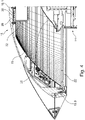
- the figure 1 shows a longitudinal section of a mono-reflector operating room light known from the prior art.
- This consists essentially of an upper housing top part 2, a lower lower glass ring 4, an essentially parabolic main reflector 6, a light module 10 attached to a heat sink 8 on the inside of the housing top part 2, a cover plate 12 for closing the lower light exit surface and a light exit surface in this arranged linear gear 14 on the top of a roof or saddle-shaped deflection reflector 16 is arranged adjustable in height.
- a plug-in coupling 18 is provided laterally in the lower glass ring 4, with which the operating room light can be fastened to a linkage (not shown).
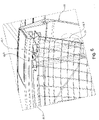
- figure 2 shows a longitudinal section through a monoreflector surgical light according to the invention.
- This also essentially comprises a bowl-shaped housing upper part 18, an annular main reflector 19 surrounding the center with the vertically extending optical axis, a lower glass ring 20, a cover plate 22 and a height-adjustable via a linear gear 24 and located in the center of the cover plate 22 recorded deflection reflector 26.
- the upper housing part is designed as a trough-shaped, one-piece die-cast aluminum housing and includes a housing top with an upper vertex 18.1 from which it extends with a uniform curvature to the light exit surface on which the cover plate 22 is arranged.
- the linear gear 14 with the pointed or saddle-shaped deflection reflector is in the center of the cover plate, ie aligned with the optical central axis in the main beam direction of the light 26 attached.
- the fastening plane 18.2 is formed parallel to and offset upwards from the cover plate 22 is.
- the upper light entry opening of the main reflector 19 is almost immediately adjacent to the attachment plane 18.2 or is located close to it, which means that the overall height is reduced according to the invention by a quarter to a third compared to the prior art becomes particularly clear.
- the cover 32 which is made of black plastic as a plastic injection molded part, has an inner shoulder at its upper end, which in the installed position rests against the outer edge of the collimator lens 30 and the LED circuit board 28 and together encompasses them on the outside, where the cover is screwed or latched to the fastening level 18.2 is.
- the figure 3 shows the surgical light during assembly, i.e. in the assembly position, with the shell-shaped upper housing part 18 being arranged on a non-illustrated surface, in a holder or the like with the upper side of the upper housing part 18 facing downwards and then the individual components based on the Reference level serving attachment level 18.2 are used in the upper housing part 18, in the present case the LED circuit board 28 and the collimator lens 30 are already mounted on the attachment level 18.2.
- the panel 32, the LED circuit board 28 and the collimator lens 30 are screwed to the mounting plane 18.2, then the main reflector 19 is inserted and with six evenly spaced on a circle, in figure 3 upwardly directed, but arranged below in the installed position, outwardly protruding mounting brackets 19.1 in recordings 18.4, which on a total of six on the inside of the upper part of the housing on a circle evenly from each other spaced and extending to the light exit opening mounting domes 18.3 are used and screwed to these mounting domes 18.3.
- One of these mounting domes 18.3 is enlarged in the figure 6 shown.
- this includes the receptacle 18.4 in the middle, which is offset downwards from the plane of the light exit surface formed by the support for the cover pane 22.
- the main reflector 19 has a circumferential outer flange 19.2 and includes recesses so that it can be placed on the fastening domes 18.3.
- the rotatable handle may further include a central camera encased by a rotatable sleeve, with which an operation may be filmed.
Landscapes
- Engineering & Computer Science (AREA)
- General Engineering & Computer Science (AREA)
- Securing Globes, Refractors, Reflectors Or The Like (AREA)
- Non-Portable Lighting Devices Or Systems Thereof (AREA)
- Fastening Of Light Sources Or Lamp Holders (AREA)
- Arrangement Of Elements, Cooling, Sealing, Or The Like Of Lighting Devices (AREA)
Description
- Die Erfindung betrifft eine Monoreflektor-Operationsraum-Leuchte (OP-Leuchte), umfassend ein zumindest abschnittsweise dom- bzw. hauben- oder schalenförmiges Gehäuseoberteil mit einer in Einbaulage nach oben gerichteten Gehäuseoberseite und einer nach unten gerichteten Gehäuseinnenseite, welches vorzugsweise ausgebildet als Aluminiumdruckguss-Körper, ein innenseitig an der Gehäuseinnenseite des Gehäuseoberteils angeordnetes LED-Leuchtmittel zur Erzeugung eines in einer Primärlichtrichtung strahlenden Lichtstroms, der auf einen in einer Strahlungsrichtung vor dem LED-Leuchtmittel angeordneten Umlenkreflektor trifft, welcher den Lichtstrom seinerseits zurück auf einen in dem Gehäuseoberteil angeordneten Hauptreflektor lenkt, der den Lichtstrom durch eine mit einer Abdeckscheibe verschlossenen Lichtaustrittsöffnung des Gehäuseoberteils zur Ausleuchtung einer Sehaufgabe lenkt. Die Abdeckscheibe ist an einem unteren Auflage- bzw. Befestigungsrand angeordnet.
- Monoreflektor-OP-Leuchten umfassend ein zentral angeordnetes Leuchtmittel mit einem in Strahlungsrichtung vor diesem angeordneten optischen System, bieten im Gegensatz zu sogenannten Mehrfeldleuchten mit mehreren um einen mittleren Halter herum und zur Fokussierung schwenkbar an diesem Halter befestigten Lichtfeldern, eine verbesserte Tiefenausleuchtung einer Wunde, während der OP und bedürfen insofern weniger Nachjustierung als Mehrfeldleuchten.
- Eine derartige Monoreflektor-OP-Leuchte hat den Vorteil einer besonders hohen Tiefenausleuchtung, also eines relativ hohen Bereichs um den Bereich der maximalen Leuchtdichte, in dem mindestens 60 Prozent dieser maximalen Leuchtdichte erzielt werden, um bei einer Operation die Wunde ohne Lichtverlust und Nachjustierung bzw. Fokussierung ausleuchten zu können.
- Die aus dem Stand der Technik bekannten Monoreflektor-Operationsraum-Leuchten umfassen ein dom- oder schalenförmig ausgebildetes Gehäuseoberteil, an dessen Innenseite am oberen Scheitelpunkt eines Halteflansches montiert ist, an dem ein sich konisch in Strahlungsrichtung aufweitendes Lichtmodul befestigt ist, das in dem Gehäuseoberteil aufgenommen ist und sich vom Oberende bis zum Unterende erstreckt. Dieses Lichtmodul umfasst unmittelbar befestigt an dem als Kühlkörper fungierenden Halteflansch eine LED-Platine mit mehreren rasterförmig angeordneten LEDs sowie eine diese LED-Platine umschließende, sich konisch nach unten in Strahlungsrichtung erweiterndes und hohlpyramidisches Modulgehäuse an dessen innerer Mantelfläche mehrere Reflektoren angeordnet sind. An dem unteren Ende der OP-Leuchte ist ein sattelförmiger bzw. spitz zulaufender Umlenkreflektor angeordnet, welcher den direkt auftreffenden Lichtstrom seitlich nach oben auf den das Lichtmodul umgebenden Hauptreflektor lenkt und von diesem durch die Lichtaustrittsöffnung und die Abdeckscheibe auf die Sehaufgabe lenkt.
- Ein solches Lichtmodul ist z.B. das ITOS SL-Modul der Firma OSRAM. Ein solches Lichtmodul stellt ein integrales Komplettmodul dar, welches in dem umgebenden Gehäuse am oberen Ende die LED-Platine und mehrere Reflektoren umfasst. Gleichzeitig bestimmt dieses wesentlich die Bauhöhe der OP-Leuchte, weil die Monoreflektor-OP-Leuchte mindestens so groß wie die Längsrichtung des Modulgehäuses sein muss, um dieses aufnehmen zu können. Bei der Montage derartiger Monoreflektor Leuchten müssen zunächst einzelne Baugruppen vormontiert und diese Baugruppen dann zur OP-Leuchte endmontiert werden. Dabei müssen die Baugruppen mehrfach umgedreht und gehandhabt werden. Eine erste Baugruppe ist der in Einbaulage unten gelegene Unterglasring mit der die Lichtaustrittsöffnung verschließenden Glasscheibe und dem im Wesentlichen als parabelförmiges Ringsegment ausgebildeter Hauptreflektor mit einer oberseitigen Öffnung zum Einsetzen des Lichtmoduls. Eine zweite Baugruppe bildet das Gehäuseoberteil, auch als "Haube" bezeichnet, mit dem innenseitig daran befestigten Lichtmodul. Dieses Lichtmodul wird in das umgedrehte, schüsselförmige Gehäuseoberteil eingesetzt und an dem innenseitig in dem Gehäuseoberteil vorgesehenen Halteflansch verschraubt. Sodann wird das Gehäuseoberteil zusammen mit dem Lichtmodul um 180 Grad gedreht und von oben in die oberseitige Öffnung des Hauptreflektors eingesetzt, der dann auf den Unterglasring mit der aufgenommenen Abdeckscheibe eingesetzt ist. Schließlich werden das Gehäuseoberteil und der Unterglasring an einer Trennstelle miteinander verschraubt und über eine an der Außenseite Dichtung abgedichtet.
- Gattungsgemäße Monoreflektor-OP-Leuchten sind aus der
DE 10 2012 201 706 A1 der Anmelderin und derCN 104 100 878 A bekannt. OP-Leuchten anderer Art sind aus derDE 20 2013 006 570 U1 ,WO 87/00603 A1 DE 25 35 556 A1 ,WO 2013/000639 A2 sowieUS 4,600,979 A bekannt. - Ferner ist eine LED-OP-Leuchte ohne einen Umlenkreflektor aus der
DE 10 2007 042 646 A1 der Anmelderin bekannt. Zudem ist eine LED-Beleuchtungsvorrichtung aus derDE 10 2009 012 138 A1 bekannt. Eine gattungsfremde Lampe ist zudem aus derUS 2010/0254128 A1 bekannt. - Die Baugruppen müssen insofern zusammengesetzt und dann die Baugruppen zur OP-Leuchte miteinander verbunden und zueinander ausgerichtet werden. Dabei müssen die einzelnen Baugruppen mehrfach umgedreht werden, was aufwendig ist. Ferner ist die Bauhöhe dieser bekannten OP-Leuchten hauptsächlich bedingt durch das Lichtmodul relativ hoch, so dass diese relativ groß und schwer sind.
- Ausgehend von diesem Stand der Technik liegt der Erfindung die Aufgabe zugrunde, diese Nachteile zumindest teilweise zu vermeiden und insbesondere eine Monoreflektor-OP-Leuchte vorzusehen, die kompakter aufgebaut und einfacher zu montieren ist.
- Die Erfindung betrifft eine Monoreflektor-OP-Leuchte mit den Merkmalen des Anspruchs 1.
- Erfindungsgemäß wird diese Aufgabe bei einer Monoreflektor-OP-Leuchte der eingangs genannten Art im Wesentlichen bereits dadurch gelöst, dass das Gehäuseoberteil einteilig ausgebildet ist, welches sich unterbrechungsfrei von einem Oberende bis zu einem Unterende zur Bildung eines geschlossenen Referenzsystems erstreckt. Das Gehäuseoberteil weist insofern auf einer Gehäuseinnenseite eine als Referenzebene dienende Befestigungsebene für die Bestandteile des optischen Systems auf. Das optische System umfasst zumindest eine LED-Platine, eine Vorsatzoptik zur Lichtlenkung des von der mindestens einen LED-Platine erzeugten Lichtstroms sowie vorzugsweise zusätzlich eine im Wesentlichen als Hohlzylinder ausgebildete Blende, welche die LED-Platine und die Vorsatzoptik in Einbaulage außenseitig umschließt bzw. einfasst. Die LED-Platine, die Vorsatzoptik und die optionale Blende sind als Teile des optischen Systems auf der Befestigungsebene montierbar bzw. montiert. Zudem können mehrere von der Referenzebene beabstandete Befestigungspunkte auf anderen Befestigungsebenen für weitere Bestanteile des optischen Systems vorgesehen sein, insbesondere für den Hauptreflektor. Das Gehäuseoberteil bildet durch diese Ausbildung ein in sich geschlossenes Referenzsystem, welches die optisch optimale Ausrichtung bzw. Anordnung der Bauteile in der optischen Sollposition bei der Montage garantiert. Vorteilhafte Weiterentwicklungen sind in den Unteransprüchen wiedergegeben. Das Referenzsystem wird somit gebildet durch die Befestigungsebene, welche den Nullpunkt bzw. Bezugspunkt des Referenzsystems bildet, und mehreren davon beabstandeten Befestigungspunkten auf anderen Befestigungsebenen für Bestandteile des optischen Systems, wobei natürlich auch auf der Befestigungsebene aufeinander aufbauend Bestandteile des optischen Systems befestigt werden können, wie die LED-Platine, eine Vorsatzoptik und eine vorzugsweise diese beiden ersten Bauteile umschließende Blende.
- Diese erfindungsgemäße Ausgestaltung hat entscheidende Vorteile. Zum einen wird kein Modulgehäuse mehr benötigt, so dass der für dieses benötigte Bauraum und insbesondere die Leuchtenhöhe nicht mehr erforderlich, was den Gestaltungsspielraum in technischer als auch unter Designaspekten erweitert. Somit kann die Bauhöhe der erfindungsgemäßen OP-Leuchte um etwa ein Viertel bis ein Drittel im Vergleich zu bestehenden Monoreflektor-OP-Leuchten reduziert werden. Das vorgenannte ITOS Modul aus dem Stand der Technik benötigt nämlich seitlich an dem Modulgehäuse angeordnete Spiegel als Reflexionsflächen zum Bündeln des Lichts in die gewünschte Lichtrichtung, bedingt aber die vordefinierte Bauhöhe durch das Gehäuse des Moduls wesentlich. Erfindungsgemäß ist dieses Gehäuse nicht mehr notwendig, weil die Kollimatorlinsen das von den LEDs ausgestrahlte Licht in Hauptstrahlrichtung bündeln.
- Somit wird durch die erfindungsgemäße Ausbildung die Montage der Leuchte deutlich vereinfacht. Für die Montage muss nämlich nur noch das einteilige, vorzugsweise schalenförmige Leuchtengehäuse mit der Leuchtengehäuseoberseite nach unten und der Lichtaustrittsöffnung nach oben gerichtet auf einer Unterlage aufgesetzt werden. Sodann können alle notwendigen Bauteile an der Innenseite befestigt werden, und zwar aufbauend auf die Befestigungs- bzw. Montageebene, welche somit als Referenzebene für das optische System dient.
- Ein besonderer Aspekt der Erfindung liegt in der Ausbildung der Befestigungsebene als Referenzebene für das optische System umfassend LED-Platine, Vorsatzoptik und vorzugsweise die Blende sowie zusätzlich auch dem Umlenkreflektor, dem Hauptreflektor und der Abdeckscheibe, welches die Montage und die Ausrichtung zueinander zur Erzielung eines optimierten optischen Systems somit vereinfacht und durch die erfindungsgemäße einteilige Ausbildung des Gehäuses erst möglich ist, weil nicht mehrere Gehäuseteile neben den optischen Systemen miteinander montiert und ausgerichtet werden müssen.
- Für die Befestigung der Blende und/oder des Hauptreflektors und weitere Komponenten des optischen Systems können aber auch andere Befestigungsmittel entsprechend beabstandet von der Befestigungsebene vorgesehen sein.
- Diese anderen Befestigungsmittel definieren bevorzugt die weiteren Befestigungsebenen angeordnet in Sollabständen zu der Befestigungsebene für die Befestigung des Hauptreflektors und weiterer optischer Komponenten in der jeweiligen optischen Sollposition. Der Hauptreflektor kann z.B. radial vom Umfangsrand abstehende Befestigungslaschen umfassen, die auf einer entsprechenden weiteren Befestigungsebene aufliegen und in dieser optischen Sollposition befestigbar sind, z. B. mittels Schrauben.
- Diese weitere Befestigungsebene für den Hauptreflektor kann z. B. auch entgegen der Strahlungsrichtung nach oben versetzt an einem unteren Auflage- bzw. Befestigungsrand für die Abdeckscheibe ausgebildet sein, z. B. in Form von Ausnehmungen, in welche die Befestigungslaschen des Hauptreflektors eingreifen und aufliegen. Ferner sind Befestigungsdome oder Auflagen für die Auflage der Abdeckscheibe vorgesehen, welche auch über einen gegenüber der Lichtaustrittsebene versetzt angeordneten Außenrand des Gehäuseoberteils ausgebildet sind und ferner ausgebildet zur Befestigung des Hauptreflektors sind. Im bevorzugten Fall erstrecken sich diese stützen- oder stabförmig ausgebildeten und voneinander beabstandeten Befestigungsdome über eine durch den Außenrand des Gehäuseoberteils definierte Ebene hinaus. Diese Befestigungsdome umfassen als Teil des Referenzsystems Auflager, welche die weitere Befestigungsebene zur Befestigung des Hauptreflektors bilden. Vorzugsweise umfassen die Befestigungsdome radial innseitige Taschen oder Ausnehmungen, in welche radial nach außen abstehende Befestigungslaschen am unteren Lichtaustrittsende des Hauptreflektors in Einbaulage einlegbar und dort lagefixierbar sind.
- Diese Befestigungsdome können also Aufnahmen ausgebildet zur Aufnahme bzw. Befestigung des Hauptreflektors umfassen. Besonders bevorzugt umfasst das untere Lichtaustrittsende des Hauptreflektors vom Außenrand nach außen abstehende Befestigungslaschen, die in diese Aufnahmen der Befestigungsdome einsitzen und dort verschraubt sind. Somit bilden auch diese Aufnahmen, die vorzugsweise nach unten versetzt von der Befestigungsebene für die Abdeckscheibe sind, einen Bestanteil des optischen Referenzsystems.
- Das Gehäuseoberteil erstreckt sich somit von seinem vorzugsweise geschlossenen Oberende bis zu dem nach unten offenen Unterende, welches die Lichtaustrittsebene definiert, wobei dieses Unterende durch Befestigungsdome, die über den eigentlichen Außenrand des Gehäuseoberteils vorstehen, für die Auflage der Abdeckscheibe gebildetist.
- Wenn das Gehäuseoberteil bei der bevorzugten Ausbildung als im Wesentlichen parabolisch, schalen- oder wannenförmiger Körper mit einem Scheiteilpunkt ausgebildet ist, ist diese Befestigungsebene vorzugsweise an der Gehäuseinnenseite im Bereich dieses Scheiteilpunktes ausgebildet und erstreckt sich somit quer zur mittleren vertikalen Rotationsachsachse bzw. optischen Achse der OP-Leuchte.
- Die Befestigungsebene ist bevorzugt als Kühlfläche ausgebildet bzw. optimiert zur Realisierung einer möglichst hohen Wärmeabführung und damit bewirkten Wärmeaufnahme durch das auch als Kühlkörper fungierende Gehäuseoberteil. Dieses erfolgt insbesondere dadurch, dass die Befestigungsebene nicht durchgängig geschlossen flächig ausgebildet ist, sondern eine Vielzahl von Rippen, Rillen und Vertiefungen aufweist, die vorzugsweise symmetrisch angeordnet sind, insbesondere umfassend mehrere ringförmig von einem Mittelpunkt konzentrisch sich nach außen verbreiternden und mit ihren Oberkanten die Befestigungsebene definierenden Ringflächen mit jeweils sich vom Mittelpunkt sicher vergrößerndem Radius und dazwischen ausgebildeten Ausnehmungen bzw. Freiflächen. Diese so gebildeten Ringflächen können durch Stege gekreuzt werden, z.B. sich kreuzend durch den Mittelpunkt sich erstreckende Stege, welche die konzentrisch sich verbreiternden Kreisringe kreuzen. Besonders bevorzugt ist die so gebildete Befestigungsebene einstückig an dem Gehäuseoberteil ausgebildet.
- Beim Stand der Technik wurden nämlich die Abdeckscheibe und der Hauptreflektor in einem Unterglasring montiert und waren daher häufig nicht optimal zu dem im Oberteil montierten optischen System ausgerichtet und mussten insofern aufwendig ausgerichtet werden, wozu Fachpersonal benötigt wird. Bei der Erfindung sind hingegen alle Komponenten im Gehäuseoberteil angeordnet und deshalb automatisch durch das Referenzsystem optimal optisch ausgereichtet werden. Bei der Erfindungsgemäßen OP-Leuchte fungiert der Unterglasring nur noch zur Zentrierung der Abdeckscheibe, und ist somit völlig unabhängig vom optischen System der OP-Leuchte.
- Bevorzugt weist die Abdeckscheibe eine geätzte Oberfläche mit einem besonderen Glanzgrad zur Realisierung eines diffusen Lichtüberganges auf.
- Diese Trennebene zwischen Abdeckscheibe und Gehäuse erstreckt sich vorzugsweise in einer Ebene entlang des äußeren, in Einbaulage unten angeordneten Umfangsrands des Gehäuseoberteils, was ebenfalls die Montage vereinfacht.
- Vor der LED-Platine wird vorzugsweise eine mindestens eine Kollimatorlinse umfassende Vorsatzoptik angeordnet, welche das von den zugeordneten LED ausgestrahlte Licht entsprechend der zu realisierenden Sehaufgabe zu dem Lichtstrom fokussiert bzw. bündelt.
- Zwischen den beiden Fügepartnern, also der LED Platine einerseits und der Vorsatzoptik andererseits sind zur weiteren Montagevereinfachung vorzugsweise zumindest ein Zentriermittel vorgesehen. Als Zentriermittel wird eine Vorrichtung verstanden, welches die Vorsatzoptik zentriert vor der LED Platine ausrichtet, damit die eine oder mehreren Optiken, insbesondere ausgebildet als mindestens eine Linse, besonders bevorzugt mindestens eine Kollimatorlinse, korrekt entlang der jeweiligen optischen Achse der zugehörigen LED angeordnet ist.
- Bei der besonders bevorzugten Ausbildung sind neben den Zentriermitteln zudem Lagefixiermittel vorgesehen, also Mittel, welche neben der Zentrierung auch die Anordnung der Vorsatzoptik im korrekten Montagewinkel vor der LED Platine gewährleisten und diese fixieren, damit die an auf der Vorsatzoptik vorgesehene mindestens eine Linse entlang der optischen Achse einer zugeordneten LED ausgerichtet ist.
- Diese Zentrier- und/oder Lagefixermittel können entweder als zusätzliche Bauteile ausgebildet sein oder, was bevorzugt ist, einstückig an den Fügepartnern (Vorsatzoptik und LED-Platine) vorgesehen sein.
- Dieses ist natürlich von besonderer Bedeutung, wenn, was bei der bevorzugten Ausführungsform der Fall ist, die LED-Platine mehrere einzelne LEDs umfasst, die in einem regelmäßigen Muster auf der Platine angeordnet sind, und die Vorsatzoptik mehrere einzelne, den einzelnen LEDs zugeordnete Linsen umfasst, welche also in Einbaulage korrekt entlang der jeweiligen optischen Achse ausgerichtet sein müssen.
- Bevorzugt und besonders einfach ist die Ausbildung der Zentrier-und/oder der Lagefixiermittel als Stifte, die in Öffnungen an dem jeweiligen Fügepartner in Einbaulage eingreifen.
- Die erfindungsgemäße Lösung ist insofern besonders einfach zu montieren, weil durch diese Zentrier- und Lagefixiermittel die einzelnen Bauteile selbstzentrierend ausgebildet sind und somit die einzelnen Komponenten des optischen Systems, also dem auf Befestigungsebene angeordneten LED-Platine, der Vorsatzoptik bzw. Linse und der Blende Zentriermittel zur relativen Ausrichtung entlang der optischen Achse ausgebildet sind, also z.B. eine Zentrierung, welche die korrekte axiale Ausrichtung, und/oder eine Winkeljustierung, welche die korrekte Winkelausrichtung der einzelnen Bauteile zueinander bei der Montage und/oder Reparatur gewährleisten. Das Gehäuseoberteil bildet somit ein einstückiges, durchgängiges Referenzsystem, wodurch besonders geringe Toleranzen im Gesamtsystem auftreten werden, jedenfalls aber deutlich geringere Toleranzketten als beim Stand der Technik mit mehreren zusammengesetzten Gehäuseteilen.
- Vorzugsweise umfassen die Zentriermittel einen mittig zwischen der LED-Platine und der Vorsatzoptik ausgebildeten Zentrierstift und die Lagefixiermittel mehrere von diesem beabstandete Positionierstifte. Diese Positionierstifte realisieren bei einer Vorsatzoptik mit mehreren Linsen den korrekten Sitz der einzelnen Linsen oberhalb der ihnen zugeordneten LEDs der LED-Platine.
- Eine besonders gute Lichtlenkung in der Primärlicht- bzw. Hauptstrahlrichtung auf den Umlenkreflektor wird durch Anordnung einer Blende um die LED-Platine und in Strahlungsrichtung vorgesetzte Vorsatzoptik (Linse bzw. Linsenanordnung umfassend mehrere Linsen, besonders bevorzugt ausgebildet als mindestens eine Kollimatorlinse) realisiert. Eine besonders gute Vermeidung von ungewünschtem seitlichem Streulicht (nicht definiert auf reflektierende Flächen treffendes Licht) wird dadurch realisiert, dass diese Blende zumindest innenseitig nicht reflektierend ausgebildet ist. Hierzu ist die Blende vorzugsweise aus einem schwarzen Werkstoff gefertigt und insbesondere ausgebildet Kunststoff-Spritzgussteil. Die Blende dient erfindungsgemäß nicht nur der Lichtlenkung, sondern ist auch zur Absorption von Streulicht ausgebildet, indem es die LED-Platine und die Vorsatzoptik umfänglich umschließend einfasst. Eine besonders gute Vermeidung dieses Streulichts wird durch eine raue Ausbildung des Materials zumindest an der der LED-Platine zugewandten Innenseite der Blende erzielt, womit eine diffuse Lichtstreuung realisiert wird. Ohne diese Blende besteht nämlich doch die geringe Möglichkeit des Austritts einzelner Lichtstrahlen in den Hauptreflektor, welche ungewünschte Lichteffekte im erzeugten Beleuchtungsfeld hervorrufen können.
- Bevorzugt ist diese Blende im Wesentlichen als Hohlzylinder ausgebildet, der die LED-Platine und die Vorsatzoptik in Einbaulage umfänglich bzw. außenseitig umschließt. Bevorzugt ist die Blende ausgebildet, um die Vorsatzoptik in Einbaulage auf die LED-Platine zu drücken. Dieses kann bevorzugt z.B. durch einen an der Innenseite der Blende ausgebildeten Absatz, Rand oder dergleichen erfolgen, der geometrisch angepasst ist zur Anlage gegen eine Außenkante der Kollimatorlinse, so dass die Blende mit diesem Absatz oberseitig auf der Außenkante der Kollimatorlinse aufliegt und diese somit gegen die LED Platine anpresst.
- Diese Blende richtet den erzeugten Lichtstrom gerichtet entlang der optischen Achse in Hauptstrahlrichtung ohne Streulichtbildung auf den in Strahlrichtung davor in der Abdeckscheibe angeordneten Umlenkreflektor. Dieser Umlenkreflektor ist vorzugsweise der über eine Fokussiereinheit höhenverstellbar, z.B. umfassend ein Lineargetriebe. Das Licht wird von diesem Umlenkreflektor wieder nach oben, also entgegen der Hauptstrahlrichtung auf den ringförmig die mittlere Vertikalachse bzw. Hauptstrahlrichtung umgebenden und in dem Gehäuseoberteil aufgenommenen Hauptreflektor gelenkt.
- Dieser Hauptreflektor weist eine an den Anwendungsfall und die zu realisierende Sehaufgabe angepasste Reflektorfläche auf, die vorzugsweise mehrere einzelne Reflektorflächen umfasst. Als besonders zweckmäßig hat sich eine vorzugsweise regelmäßig an der Oberfläche des Hauptreflektors verteilte Facettenstruktur erwiesen, die auch zonal unterschiedlich ausgebildet sein kann. Möglich ist auch in Abhängigkeit von der umzusetzenden Sehaufgabe die Kombination von zonal unterschiedlich ausgebildeten Krümmungsbereichen und/oder Einzelreflektionsflächen, also einzelnen durch einen umgebenden Rand abgegrenzte Reflektionsflächen mit jeweils definierter Krümmung, wobei diese vorzugsweise unmittelbar aneinander angrenzen und somit eine Art durchgehende Wabenstruktur bilden. Möglich ist auch die Kombination einer Wabenstruktur mit unmittelbaren oder mit Abstand aneinander angrenzenden Einzelreflektionsflächen mit anderen geometrisch ausgebildeten Reflektionsbereichen, z.B. einer Ringstruktur und/oder Wellenstruktur mit konzentrisch sich erweiternden Ringabschnitten auf dem Hauptreflektor.
- Bei der Erfindung bilden somit die auf der Montageebene befestigte mindestens eine LED-Platine, die in Strahlungsrichtung davor angeordnete Vorsatzoptik und die vorzugsweise diese beiden Bauteile umschließende Blende das LED-Modul, welches völlig kundenindividuell anpassbar ist und ausgestaltet werden kann und welches mit einer Bauhöhe von 50 bis 100 mm, insbesondere 68 mm eine wesentliche geringere als bestehende LED-Module aufweist.
- Eine weitere Vereinfachung der Montage kann dadurch erzielt werden, dass zwischen dem Gehäuseoberteil und dem Hauptreflektor eine Lagefixierung vorgesehen ist, die eine sowohl axiale und/oder rotationsmäßige Anordnung im Verhältnis zueinander in genauer Ausrichtung des Hauptreflektors zu der Montageebene mit dem LED-Modul und dem Gehäuse ermöglicht. Vorzugsweise umfassen diese Lagefixierung Vorsprünge welche in entsprechende Nuten eingreifen. Besonders bevorzugt sind Vorsprünge am radialen äußeren Rand des Hauptreflektors, welche in Ausnehmungen der Haube bzw. des Gehäuseoberteils einsetzbar sind.
- Eine weitere Montagevereinfachung kann dadurch realisiert werden, dass zwischen dem Gehäuseoberteil und dem die Abdeckscheibe haltenden Unterglasring eine beim Zusammenbau wirkende Justierung vorgesehen ist, vorzugsweise umfassend komplementär wirkende Anlaufschrägen, welche beim Zusammensetzen oder nur mit dem jeweiligen Gegenpart abgleiten und somit nach dem Eindrehen der Befestigungsmittel eine Presspassung zwischen den Fügepartnern realisieren. Ferner können diese Fügepartner lagefixierend für die Abdeckscheibe ausgebildet sein, um diese also mittig genau zu positionieren und umfänglich zu halten.
- Erfindungsgemäß muss zum Verschließen der OP-Leuchte nur noch der Unterglasring mit dem Gehäuseoberteil verschraubt werden, und zwar nachdem alle anderen Komponenten einschließlich der Abdeckscheibe im bzw. auf dem als Referenzsystem dienenden Gehäuseoberteil montiert sind. Bei der Montage wird also auch die Abdeckscheibe an dem Referenzsystem ausgerichtet und nur noch durch den Unterglasring in der Sollposition fixiert. Dieses ist ein weiterer entscheidender Vorteil zur Vereinfachung der Montage aller Komponenten in dem durch das Gehäuseoberteil gebildete Referenzsystem, das auf die als Referenzebene fungierende Montageeben so aufgebaut ist, dass alle Komponenten nur in der optischen Sollposition angeordnet werden können. Weil Fehler in der Montage somit ausgeschlossen sind, kann die Montage auch durch ungeschultes Personal durchgeführt werden.
- Zur einfachen Positionierung in der optischen Sollposition und zur Lagefixierung weist der Hauptreflektor vorzugsweise mindestens eine Lagefixierung auf, besonders bevorzugt umfassend seitlich abstehende Laschen, die höhenmäßig referenziert sind zur Montageebene des Gehäuseoberteils. Zur Aufnahme dieser Laschen weist das Gehäuseoberteil von der Montageebene definiert beabstandete Aufnahmen bzw. Vertiefungen für die Aufnahme dieser auf in Einbaulage auf.
- Die Abdeckscheibe, welche die Lichtaustrittöffnung verschließt, wird auch bei der erfindungsgemäßen Monoreflektor-OP-Leuchte durch einen Unterglasring gehalten, der die Außenkante der Abdeckscheibe in Einbaulage unterseitig umgreift. Für dieses Umgreifen umfasst der Unterglasring vorzugsweise einen Auflage- bzw. Halteflansch, welcher eine Auflagefläche für die Abdeckscheibe bildet und von dem sich quer zur Ebene dieser Auflagefläche ein Außenrand nach oben erstreckt, der mit dem Gehäuseoberteil verbindbar ist.
- Bei der bevorzugten Ausbildung ist der Unterglasring somit als Gehäuseunterteil ausgebildet, welches an das Gehäuseoberteil unterseitig anschließt und mit dem Gehäuseoberteil eine harmonische Einheit bildet.
- Die getrennte Ausbildung des Unterglasrings von dem allein das Referenzsystem bildenden Gehäuseoberteil ermöglicht einen höheren Gestaltungs- und Designspielraum bei der Ausbildung der OP-Leuchte. Das auch als Kühlkörper fungierende Gehäuseoberteil besteht zur Erzielung einer gewünscht hohen Wärmeaufnahmekapazität vorzugsweise aus Metall, vorzugsweise ausgebildet als Aluminiumdruckgusskörper. Solche Metallkörper müssen bei der Herstellung entformbar sein, was den Gestaltungsspielraum hinsichtlich der Ausbildung von komplexen Geometrien einschränkt, insbesondere solchen mit Hinterschnitten.
- Dieses ist z.B. besonders wichtig, wenn man Griffe an dem Gehäuseoberteil vorsehen will, welche die Hauptlast tragen. Vorzugsweise sind umfänglich um die Lichtaustrittsebene bzw. den unteren Rand des Gehäuseoberteils herum mehrere, beabstandet zueinander angeordnete Griffe vorgesehen, mit denen die OP-Leuchte verstellbar ist.
- Der Unterglasring muss hingegen nicht aus Metall bestehen, sondern kann z.B. Kunststoff aufweisen oder vollständig aus diesem bestehen, z.B. umfassend einen PUR Schaum. Dieses eröffnet besonders weite Gestaltungs- und Kostenpotentiale.
- Zwischen der Abdeckscheibe und dem Auflageflansch ist vorzugsweise eine Dichtung vorgesehen, die besonders bevorzugt als in entsprechenden Aufnahmenuten sitzende eingeschäumte Dichtungselemente oder O-Ringe umfassen. Bei der besonders bevorzugten Ausführungsform sind ein oder mehrere radial von der Mittelachse der Leuchte zueinander beabstandete Dichtungselemente vorgesehen. An einem mit dem Gehäuseoberteil verbindbaren oberen Befestigungsende des Außenrands des Unterglasrings ist vorzugsweise eine Nut-Federverbindung mit einer weiteren Dichtung vorgesehen, so dass also die Monoreflektor-OP-Leuchte zwei in der Höhe versetzt zueinander angeordnete Dichtebenen aufweist, nämlich eine erste - untere - Dichtebene zwischen der Abdeckscheibe und dem Auflageflansch des Unterglasrings und eine zweite - obere - an der Verbindungsstelle des Außenrands mit dem Gehäuseoberteil. Durch die die innenliegende Dichtflächen wird eine besonders einfache Reinigung der Leuchte in der sterilen Operationsraum-Umgebung ermöglicht. Dieses somit mehrstufige Dichtsystem ist besonders vorteilhaft für die Realisierung höherer Schutzarten, vorliegend insbesondere IP54.
- An dem Unterglasring ist zur Montagevereinfachung bzw. korrekten Aufsetzen des Unterglasrings auf das Gehäuseoberteil und korrekten Ausrichtung der Abdeckscheibe ein Lagefixierungsmittel vorgesehen, das insbesondere mehrere umfänglich voneinander beabstandete Anlaufschrägen umfasst, gegen welche die Außenkante der Abdeckscheibe so abgeleitet, dass beim vollständigen Aufsetzen des Unterglasrings auf das Gehäuseoberteil die Abdeckscheibe mittig justiert ist.Die Erfindung betrifft insofern unabhängig von der Monoreflektor-Operationsraumleuchte (OP-Leuchte) an sich ferner ein Verfahren zur besonders effizienten, also kostengünstigen Montage einer solchen Operationsraumleuchte, wobei diese Montage insbesondere durch ungeschultes Personal durchgeführt werden kann, weil das Leuchtengehäuse erfindungsgemäß ein eigenes Referenzsystem für die optisch korrekte Montage und optisch optimale Ausrichtung der Komponenten in diesem Referenzsystem, also in der optischen Sollposition, bereitstellt, welche eine fehlerhafte Montage nahezu vollständig ausschließt.
- Dieses Montageverfahren umfasst zumindest die folgenden Verfahrensschritte:
- Aufsetzen einer ein Referenzsystem bildendes Gehäuseoberteil umfassend eine in Einbaulage nach oben gerichtete aber in Montagelage nach unten gerichtete Gehäuseoberseite und eine in Einbaulage nach unten gerichtete und in Montagelage nach oben gerichtete Gehäuseinnenseite mit einer eine Referenzebene bildendenden Befestigungsebene auf der Gehäuseinnenseite,
- Befestigen eines LED-Leuchtmittels umfassend mindestens eine LED-Platine mit mindestens einer LED zur Erzeugung eines Lichtstroms auf der Befestigungsebene, welche als Bezugspunkt eines Referenzsystems für ein durch die Operationsraumleuchte gebildetes optisches System fungiert,
- Anordnen einer Vorsatzoptik auf dem Leuchtmittel,
- Anordnen eines Hauptreflektors, der vorzugsweise die Geometrie eines im Wesentlichen parabolisch ausgebildeten Rotationskörpers aufweist in dem Gehäuseoberteil um die LED-Platine und die Vorsatzoptik herum, und
- Anordnen einer Abdeckscheibe mit einem darin angeordneten Umlenkreflektor, der mittels eines Lineargetriebes höhenverstellbar ist zur Fokussierung der Monoreflektor-Operationsraum Leuchte, auf der Lichtaustrittsebene des Gehäuseoberteils.
- In einem weiteren Verfahrensschnitt kann vor dem Einsetzen des Hauptreflektors eine Blende um die LED-Platine und die Vorsatzoptik herum befestigt werden, vorzugsweise ebenfalls auf oder an der Befestigungsebene. Alternativ kann die Befestigung von der LED-Platine der Vorsatzoptik und der Blende an der Befestigungsebene in einem Schritt erfolgen.
- Schließlich kann in einem weiteren Verfahrensschritt ein Unterglasring auf der Abdeckscheibe befestigt werden, welche einen die Abdeckscheibe in Einbaulage umfassenden Rand aufweist, welcher vorzugsweise die Abdeckscheibe vollständig umfasst. Dieser Unterglasring kann zudem innenseitig gegen den Außenrand der Abdeckscheibe wirkende Anlaufschrägen zur Lagefixierung der Abdeckscheibe in der Sollposition umfassen. Ferner kann der Unterglasring Dichtmittel zur Verbindung mit dem Gehäuseoberteil umfassen, wobei bevorzugt eine zweistufige Ausbildung des Dichtmittel realisiert ist, also eine Dichtung in zwei verschiedenen Ebenen zur Realisierung höherer Schutzarten von IP54 und höher.
- In der folgenden ausführlichen Beschreibung wird auf die beigefügten Zeichnungen Bezug genommen, die Teil dieser Erfindungsbeschreibung bilden und in denen zur Veranschaulichung spezifischer Ausführungsformen gezeigt sind, mit denen die Erfindung ausgeübt werden kann. In dieser Hinsicht wird Richtungsterminologie wie etwa "oben", "unten", "vorne", "hinten", "vorderes", "hinteres", usw. in Bezug auf die Orientierungen der beschriebenen Figur(en) verwendet. Da Komponenten von Ausführungsformen in einer Anzahl verschiedener Orientierung positioniert werden können, dient die Richtungsterminologie zur Veranschaulichung und ist auf keinerlei Weise einschränkend. Es versteht sich, dass andere Ausführungsformen benutzt und strukturelle oder logische Änderungen vorgenommen werden können, ohne von dem Schutzumfang der vorliegenden Erfindung abzuweichen. Die folgende ausführliche Beschreibung ist nicht im einschränkenden Sinne aufzufassen.
- Im Rahmen dieser Beschreibung werden die Begriffe "verbunden", "angeschlossen" sowie "integriert" verwendet zum Beschreiben sowohl einer direkten als auch einer indirekten Verbindung, eines direkten oder indirekten Anschlusses sowie einer direkten oder indirekten Integration. In den Figuren werden identische oder ähnliche Elemente mit identischem Bezugszeichen versehen, soweit dieses zweckmäßig ist.
- Bezugszeichenlinien sind Linien, die das Bezugszeichen mit dem betreffenden Teil verbinden. Ein Pfeil hingegen, der kein Teil berührt, bezieht sich auf eine gesamte Einheit, auf die er gerichtet ist. Die Figuren sind im Übrigen nicht unbedingt maßstäblich. Zur Veranschaulichung von Details können möglichweise bestimmte Bereiche übertrieben groß dargestellt sein. Darüber hinaus können die Zeichnungen plakativ vereinfacht sein und enthalten nicht jedes bei der praktischen Ausführung gegebenenfalls vorhandene Detail. Die Begriffe "oben" und "unten" beziehen sich auf die Darstellung in den Figuren. Es zeigen:
- Fig. 1
- einen Längsschnitt einer Monoreflektor-OP-Leuchte gemäß dem Stand der Technik;
- Figur 2
- einen Längsschnitt einer erfindungsgemäßen Monoreflek-tor-OP-Leuchte;
- Figur 3
- eine isometrische Explosionsdarstellung der OP-Leuchte gemäß
Figur 2 in Montagestellung zur Veranschaulichung des Ablaufs des erfindungsgemäßen Montageverfahrens; - Figur 4
- eine vergrößerte Ansicht der linken Hälfte der OP-Leuchte gemäß
Figur 2 ; - Figur 5
- einen perspektivischen isometrischen Längsschnitt der erfindungsgemäßen Leuchte in der Gebrauchsposition mit dem Gehäuseoberteil nach oben gerichtet; und
- Figur 6
- eine vergrößerte Detaildarstellung der Befestigung des Hauptreflektors im Gehäuseoberteil von oben, also in der Montageposition bei umgedrehtem Gehäuseoberteil.
- Die
Figur 1 zeigt demnach eine aus dem Stand der Technik bekannte Monoreflektor-Operationsraumleuchte im Längsschnitt. Diese besteht im Wesentlichen aus einem oberen Gehäuseoberteil 2, einem unteren Unterglasring 4, einem im Wesentlichen parabolischen Hauptreflektor 6, einem an einem Kühlkörper 8 auf der Innenseite des Gehäuseoberteils 2 befestigten Lichtmodul 10, einer Abdeckscheibe 12 zum Verschließen der unteren Lichtaustrittsfläche sowie einem in dieser Lichtaustrittsfläche angeordneten Lineargetriebe 14 auf dessen Oberseite ein Dach- bzw. sattelförmiger Umlenkreflektor 16 höhenverstellbar angeordnet ist. Seitlich in dem Unterglasring 4 ist eine Steckkupplung 18 vorgesehen, mit welcher die Operationsraumleuchte an einem nicht dargestellten Gestänge befestigbar ist. -
Figur 2 zeigt einen Längsschnitt durch eine erfindungsgemäße Monoreflektor-OP-Leuchte. Auch diese umfasst im Wesentlichen ein schüssel- bzw. schalenförmiges Gehäuseoberteil 18, einen ringförmigen die Mitte mit der sich vertikal erstreckenden optischen Achse umschließenden Hauptreflektor 19, einen Unterglasring 20, eine Abdeckscheibe 22 sowie einen über ein Lineargetriebe 24 höhenverstellbaren und in der Mitte der Abdeckscheibe 22 aufgenommenen Umlenkreflektor 26. - Das Gehäuseoberteil ist erfindungsgemäß als wannenförmiges, einstückiges Aluminiumdruckgussgehäuse ausgebildet und umfasst eine Gehäuseoberseite mit einem oberen Scheitelpunkt 18.1 von dem sich dieses unter gleichmäßiger Krümmung bis zur Lichtaustrittsfläche erstreckt, an die die Abdeckscheibe 22 angeordnet ist. In der Mitte der Abdeckscheibe, also ausgerichtet zur optischen Mittelachse ist in der Hauptstrahlrichtung des Lichts das Lineargetriebe 14 mit dem spitz zulaufenden bzw. sattelförmigen Umlenkreflektor 26 befestigt. An der Innenseite des Gehäuseoberteils 18 unterhalb des Scheitelpunkts 18.1 ist parallel versetzt nach oben zur Abdeckscheibe 22 die erfindungsgemäße Befestigungsebene 18.2 ausgeformt, auf der eine LED-Platine 28 mit einer davor angeordneten Kollimatorlinse 30 umfassend mehrere den einzelnen LEDs zugeordnete Linsen und eine hohlzylindrische Blende 32 befestigt ist.
- Deutlich erkennbar ist, dass bei der erfindungsgemäßen OP-Leuchte die obere Lichteintrittsöffnung des Hauptreflektors 19 quasi unmittelbar an die Befestigungsebene 18.2 anschließt bzw. nahe an dieser gelegen ist, wodurch die erfindungsgemäße Reduzierung der Bauhöhe um ein Viertel bis ein Drittel im Vergleich zum Stand der Technik besonders deutlich wird.
- Die aus schwarzem Kunststoff als Kunststoffspritzgussteil ausgebildete Blende 32 weist an ihrem oberseitigen Ende einen Innenabsatz auf, welcher in Einbaulage gegen den äußeren Rand der Kollimatorlinse 30 und der LED Platine 28 anliegt und diese gemeinsam außenseitig umgreift, wo die Blende mit der Befestigungsebene 18.2 verschraubt oder verrastet ist.
- Die
Figur 3 zeigt die OP-Leuchte bei der Montage, also in der Montageposition, wobei also das schalenförmige Gehäuseoberteil 18 auf einem nicht dargestellten Untergrund, in einer Halterung oder dergleichen mit der Gehäuseoberseite des Gehäuseoberteils 18 nach unten angeordnet ist und sodann die einzelnen Komponenten aufbauend auf die als Referenzebene dienende Befestigungsebene 18.2 in das Gehäuseoberteil 18 eingesetzt werden, wobei vorliegend die LED-Platine 28 und die Kollimatorlinse 30 bereits auf der Befestigungsebene 18.2 montiert sind. Zunächst wird bei der Montage die Blende 32 die LED-Platine 28 und die Kollimatorlinse 30 umfassend auf der Befestigungsebene 18.2 verschraubt, sodann der Hauptreflektor 19 eingesetzt und mit sechs gleichmäßig auf einem Kreis voneinander beabstandeten, inFigur 3 nach oben gerichteten, aber in Einbaulage unten angeordneten, nach außen abstehenden Montagelaschen 19.1 in Aufnahmen 18.4, die auf insgesamt sechs an der Innenseite des Gehäuseoberteils auf einem Kreis gleichmäßig voneinander beabstandeten und sich zur Lichtaustrittsöffnung erstreckenden Befestigungsdomen 18.3 ausgebildet sind, eingesetzt und mit diesen Befestigungsdomen 18.3 verschraubt. Einer dieser Befestigungsdome 18.3 ist vergrößert in derFigur 6 dargestellt. Deutlich erkennbar ist, dass diese mittig die Aufnahme 18.4 umfasst, die von der durch die Auflage für die Abdeckscheibe 22 gebildeten Ebene der Lichtaustrittsfläche nach unten versetzt ist. Der Hauptreflektor 19 weist zur Erhöhung der Stabilität einen umfänglich umlaufenden Außenflansch 19.2 auf und umfasst Ausnehmungen, damit dieser auf die Befestigungsdome 18.3 aufsetzbar ist. - In der
Figur 6 ist eine von mehreren der Anlaufschrägen 22.1 des Unterglasrings 22 zu erkennen, der eine in Aufschubrichtung ansteigende, also konisch ausgebildete Fügefläche aufweist, die in Einbaulage außenseitig gegen den Außenrand der Abdeckscheibe 22 drückt und diese somit lagefixiert. Von diesen Anlaufschrägen 22.1 sind in regelmäßigen Abständen zueinander beabstandet mehrere auf der Innenseite von des Unterglasrings 20 einstückig angeformt. Die Justierung des durch die OP-Leuchte erzeugten Lichtkegels erfolgt durch Drehung des mittig in der Abdeckscheibe aufgenommenen Lineargetriebes 14, wodurch der Umlenkreflektor 26 nach oben und nach unten verstellt wird. Bei einer Weiterentwicklung kann der drehbare Griff ferner eine mittige Kamera umfassen, die von einer Drehhülse umschlossen wird, mit welcher eine Operation gefilmt werden kann.
Claims (13)
- Monoreflektor-Operationsraumleuchte, umfassend ein zumindest abschnittsweise dom- bzw. haubenförmiges Gehäuseoberteil (18), vorzugsweise umfassend Aluminium, mit einem in dem Gehäuseoberteil angeordneten Leuchtmittel, ausgebildet als LED-Leuchtmittel umfassend mindestens eine LED-Platine (28) zur Erzeugung eines entlang einer optischen Achse strahlenden Lichtstroms auf einen in Strahlungsrichtung davor angeordneten optisches System umfassend einen Umlenkreflektor (26), welcher verstellbar ist und ferner eine Primärreflektionsfläche aufweist, um den Lichtstrom auf einen ebenfalls in dem Gehäuseoberteil angeordneten Hauptreflektor (19) zu reflektieren, welcher den Lichtstrom dann durch eine von einer Abdeckscheibe (22) verschlossene Lichtaustrittöffnung des Gehäuseoberteils (18) zur Ausleuchtung auf eine Sehaufgabe lenkt, wobei die Abdeckscheibe an einem unteren Auflage- bzw. Befestigungsrand angeordnet ist, wobei das Gehäuseoberteil (18) einteilig ausgebildet ist und sich unterbrechungsfrei von einem in Einbaulage nach oben gerichteten Oberende bis zu einem die Lichtaustrittsöffnung definierenden und durch die Abdeckscheibe (22) verschlossenen Unterende zur Bildung eines in sich geschlossenen Referenzsystems erstreckt, wobei das Gehäuseoberteil (18) auf einer Innenseite eine als Referenzebene dienende Befestigungsebene (18.2) für das optische System aufweist, das zumindest eine LED-Platine (28) und eine Vorsatzoptik (30) umfasst, wobei die LED-Platine (28) und die Vorsatzoptik (30) als Teile des optischen Systems auf der Befestigungsebene (18.2) angeordnet sind, und wobei von der Referenzebene beabstandete Befestigungspunkte für Bestandteile des optischen Systems vorgesehen sind, wobei das Referenzsystem ferner eine Befestigungsebene für die Befestigung des Hauptreflektors (19) aufweist, DADURCH GEKENNZEICHNET, dass die Befestigungsebene für den Hauptreflektor (19) an umfänglich voneinander beanstandeten Befestigungsdomen (18.3) ausgebildet ist, dass die Befestigungsdome (18.3) über einen gegenüber der Lichtaustrittsebene versetzt angeordneten Außenrand des Gehäuseoberteils (18) vorstehen, dass die Befestigungsdome (18.3) als Teil des Referenzsystems Auflager umfassen, welche eine Befestigungsebene zur Befestigung des Hauptreflektors (19) bilden und dass die Befestigungsdome (18.3) für die Auflage der Abdeckscheibe (22) ausgebildet sind.
- Monoreflektor-Operationsraumleuchte nach Anspruch 1, DADURCH GEKENNZEICHNET, DASS die Befestigungsebene für den Hauptreflektor (19) versetzt von der Auflagefläche für die Abdeckscheibe (22) ausgebildet ist.
- Monoreflektor-Operationsraumleuchte nach Anspruch 1 oder 2, DADURCH GEKENNZEICHNET, DASS die LED-Platine (28) mehrere LEDs umfasst und die Vorsatzoptik eine jeder LED zugeordnete Linse umfasst.
- Monoreflektor-Operationsraumleuchte nach Anspruch 1 bis 3, DADURCH GEKENNZEICHNET, DASS zwischen der LED-Platine (28) und der Vorsatzoptik (30) mindestens ein Zentrierelement und/oder mindestens ein Lagefixierelement ausgebildet sind, mit denen die LED-Platine (28) und die Vorsatzoptik (30) in einer optischen Sollposition miteinander verbindbar sind.
- Monoreflektor-Operationsraumleuchte nach Anspruch 4, DADURCH GEKENNZEICHNET, DASS das Zentrier- und/oder das Lagefixierelement einen Stift in einem ersten Fügepartner und eine mit diesem Stift in Einbaulage zusammenwirkende Öffnung in einem zweiten Fügepartner umfassen.
- Monoreflektor-Operationsraumleuchte nach einem der vorhergehenden Ansprüche, DADURCH GEKENNZEICHNET, DASS das optische System eine im Wesentlichen als Hohlzylinder ausgebildete Blende (32) umfasst, welche die mindestens eine LED-Platine (28) und die Vorsatzoptik (30) in Einbaulage außenseitig umschließt bzw. einfasst.
- Monoreflektor-Operationsraumleuchte nach Anspruch 5, DADURCH GEKENNZEICHNET, DASS die Blende (32) ferner ausgebildet ist, um Streulicht zwischen der LED-Platine (28) und der Vorsatzoptik (30) zu unterbinden.
- Monoreflektor-Operationsraumleuchte nach einem der vorhergehenden Ansprüche, DADURCH GEKENNZEICHNET, DASS die Blende (32) ausgebildet ist, um die Vorsatzoptik in Einbaulage auf die LED-Platine zu pressen.
- Monoreflektor-Operationsraumleuchte nach Anspruch 7, DADURCH GEKENNZEICHNET, DASS die Blende einen innenseitigen und komplementär zu einer Außenkante der Vorsatzoptik (30) gestalteten Absatz umfasst.
- Monoreflektor-Operationsraumleuchte nach einem der vorhergehenden Ansprüche, DADURCH GEKENNZEICHNET, DASS die Befestigungsebene (18.1) als Kühlkörper ausgebildet ist.
- Leuchtenmontageverfahren, zur Montage einer Monoreflektor-Operationsraumleuchte nach einem der vorhergehenden Vorrichtungsansprüche, umfassend die Verfahrensschritte: Aufsetzen eines ein geschlossenes Referenzsystem bildendes Gehäuseoberteil (18.1), welches sich einstückig von einer in Einbaulage nach oben gerichteten aber in einer Montagelage nach unten gerichteten Gehäuseoberseite bis zu einer durch eine Abdeckscheibe verschlossenen Lichtaustrittsöffnung erstreckt und eine in der Einbaulage nach unten gerichtete und in der Montagelage nach oben gerichtete Gehäuseinnenseite mit einer Befestigungsebene (18.2) umfasst, welche als Bezugspunkt des Referenzsystems für ein optisches System fungiert, Befestigen eines Leuchtmittels umfassend eine LED-Platine (28) zur Erzeugung eines in einer Primärlichtrichtung strahlenden Lichtstroms auf der Befestigungsebene (18.2), Anordnen einer Vorsatzoptik (30) auf der LED-Platine (28), Anordnen eines Hauptreflektors (19) auf Auflagern in einer Befestigungsebene in dem Gehäuseoberteil (18) für den Hauptreflektor (19), die an umfänglich voneinander beanstandeten Befestigungsdomen (18.3), die über einen gegenüber der Lichtaustrittsebene versetzt angeordneten Außenrand des Gehäuseoberteils (18) vorstehen, ausgebildet sind und Anordnen einer Abdeckscheibe (22) mit einem Umlenkreflektor (26), der mittels eines Lineargetriebes (14) höhenverstellbar ist zur Fokussierung der Monoreflektor-Operationsraumleuchte, auf den Befestigungsdomen an dem Gehäuseoberteil (18).
- Montageverfahren nach Anspruch 11, DADURCH GEKENNZEICHNET, DASS das optische System eine Blende umfasst, die nach dem Aufsetzen der LED-Platine (28) und der Vorsatzoptik (30) diese umfassend auf der Befestigungsebene (18.2) montiert wird.
- Montageverfahren nach einem der vorhergehenden Verfahrensansprüche, DADURCH GEKENNZEICHNET, DASS ein Unterglasring (20) auf die Abdeckschreibe (22) und das Gehäuseoberteil (18) montiert wird.
Applications Claiming Priority (1)
| Application Number | Priority Date | Filing Date | Title |
|---|---|---|---|
| DE102016121689.5A DE102016121689A1 (de) | 2016-11-11 | 2016-11-11 | Monoreflektor-Operationsraumleuchte |
Publications (2)
| Publication Number | Publication Date |
|---|---|
| EP3321571A1 EP3321571A1 (de) | 2018-05-16 |
| EP3321571B1 true EP3321571B1 (de) | 2022-05-04 |
Family
ID=60293794
Family Applications (1)
| Application Number | Title | Priority Date | Filing Date |
|---|---|---|---|
| EP17200537.3A Active EP3321571B1 (de) | 2016-11-11 | 2017-11-08 | Monoreflektor-operationsraumleuchte |
Country Status (5)
| Country | Link |
|---|---|
| US (1) | US10648646B2 (de) |
| EP (1) | EP3321571B1 (de) |
| JP (1) | JP6491726B2 (de) |
| CN (1) | CN108071976B (de) |
| DE (1) | DE102016121689A1 (de) |
Families Citing this family (4)
| Publication number | Priority date | Publication date | Assignee | Title |
|---|---|---|---|---|
| DE102016121689A1 (de) * | 2016-11-11 | 2018-05-17 | Trilux Medical Gmbh & Co. Kg | Monoreflektor-Operationsraumleuchte |
| US11486565B2 (en) * | 2019-03-21 | 2022-11-01 | Signify Holding B.V. | Adjustable light source holder, a directable spotlight and a manufacture method thereof |
| US11898720B2 (en) * | 2020-01-15 | 2024-02-13 | Man-D-Tec, Inc. | Downlight fixture housing fabrication |
| EP4350210A1 (de) * | 2022-10-04 | 2024-04-10 | Baxter Medical Systems GmbH + Co. KG | Chirurgische beleuchtungsanordnung |
Citations (1)
| Publication number | Priority date | Publication date | Assignee | Title |
|---|---|---|---|---|
| US4600979A (en) * | 1985-10-02 | 1986-07-15 | American Sterilizer Company | Passive cooling system for a luminaire |
Family Cites Families (18)
| Publication number | Priority date | Publication date | Assignee | Title |
|---|---|---|---|---|
| US2798938A (en) * | 1954-09-17 | 1957-07-09 | American Sterilizer Co | Surgical light |
| US4037096A (en) * | 1974-08-09 | 1977-07-19 | American Sterilizer Company | Illuminator apparatus using optical reflective methods |
| US4651257A (en) * | 1985-07-15 | 1987-03-17 | American Sterilizer Company | Multiple source lighting fixture |
| US4617619A (en) * | 1985-10-02 | 1986-10-14 | American Sterilizer Company | Reflector for multiple source lighting fixture |
| US4994945A (en) * | 1989-01-26 | 1991-02-19 | Kirschner Medical Corporation | Lamp system for operating theatres and the like |
| US6443596B1 (en) * | 1998-03-27 | 2002-09-03 | Hill-Rom Services, Inc. | Surgical light apparatus with improved cooling |
| DE102007042646A1 (de) * | 2007-09-10 | 2009-03-12 | Trilux Gmbh & Co. Kg | LED-OP-Leuchte |
| DE102009012138A1 (de) * | 2009-03-06 | 2010-09-09 | Osram Gesellschaft mit beschränkter Haftung | LED-Beleuchtungsvorrichtung |
| US8529102B2 (en) * | 2009-04-06 | 2013-09-10 | Cree, Inc. | Reflector system for lighting device |
| US8807799B2 (en) * | 2010-06-11 | 2014-08-19 | Intematix Corporation | LED-based lamps |
| DE102012201706B4 (de) * | 2011-02-04 | 2014-03-27 | Trilux Gmbh & Co. Kg | LED-Operationsleuchte mit Monoreflektor |
| CN202302791U (zh) * | 2011-06-29 | 2012-07-04 | 欧司朗股份有限公司 | 照明系统 |
| CN104100878A (zh) * | 2013-04-11 | 2014-10-15 | 上海吉顺医疗器械制造有限公司 | 一种二次反射式led手术无影灯 |
| DE202013006570U1 (de) * | 2013-07-22 | 2013-08-07 | Cival Medical Gmbh | Operationsleuchte |
| CN104566039B (zh) * | 2015-01-19 | 2017-01-04 | 宁波蓝野医疗器械有限公司 | 抛物线反射led口腔灯 |
| CN204593102U (zh) * | 2015-05-27 | 2015-08-26 | 上海汇丰医疗器械有限公司 | 手术灯 |
| ES1160036Y (es) * | 2016-06-16 | 2017-01-24 | Netun Solutions S L | Dispositivo luminoso movil de emergencia |
| DE102016121689A1 (de) * | 2016-11-11 | 2018-05-17 | Trilux Medical Gmbh & Co. Kg | Monoreflektor-Operationsraumleuchte |
-
2016
- 2016-11-11 DE DE102016121689.5A patent/DE102016121689A1/de not_active Ceased
-
2017
- 2017-11-08 US US15/806,579 patent/US10648646B2/en active Active
- 2017-11-08 EP EP17200537.3A patent/EP3321571B1/de active Active
- 2017-11-09 CN CN201711098617.1A patent/CN108071976B/zh not_active Expired - Fee Related
- 2017-11-09 JP JP2017216101A patent/JP6491726B2/ja active Active
Patent Citations (1)
| Publication number | Priority date | Publication date | Assignee | Title |
|---|---|---|---|---|
| US4600979A (en) * | 1985-10-02 | 1986-07-15 | American Sterilizer Company | Passive cooling system for a luminaire |
Also Published As
| Publication number | Publication date |
|---|---|
| CN108071976B (zh) | 2021-01-26 |
| JP6491726B2 (ja) | 2019-03-27 |
| US20180135834A1 (en) | 2018-05-17 |
| CN108071976A (zh) | 2018-05-25 |
| DE102016121689A1 (de) | 2018-05-17 |
| EP3321571A1 (de) | 2018-05-16 |
| US10648646B2 (en) | 2020-05-12 |
| JP2018078107A (ja) | 2018-05-17 |
Similar Documents
| Publication | Publication Date | Title |
|---|---|---|
| EP3321571B1 (de) | Monoreflektor-operationsraumleuchte | |
| EP1632713B1 (de) | Leuchte zur Ausleuchtung von Gebäudeflächen oder Gebäudeteilflächen | |
| EP2539629B1 (de) | Einbauleuchte mit basiskörper und domförmigem reflektor | |
| DE3516812C2 (de) | ||
| EP2204604B1 (de) | Leuchte | |
| EP1392999B1 (de) | Taschenlampe | |
| EP2299163B1 (de) | Operationsleuchte | |
| EP0637715B1 (de) | Vorrichtung zur lösbaren Arretierung einer Lampe an einem Reflektor eines Fahrzeugscheinwerfers | |
| EP2332491B1 (de) | Lichthärtgerät für Dentalzwecke | |
| DE2210242A1 (de) | Beleuchtungskörper | |
| EP3165818B1 (de) | Innen- oder aussenleuchte, insbesondere strassenleuchte, mit verlagerbarer freiformlinse | |
| DE3926618A1 (de) | Reflektorleuchte | |
| EP2796770B1 (de) | Leuchte mit einer Lichterzeugungseinheit und einem Rahmenelement | |
| EP2264362B1 (de) | LED-Scheinwerfer und Beleuchtungssystem mit einem solchen Scheinwerfer | |
| EP0684425A2 (de) | Leuchte mit mindestens einem Leuchtmittel | |
| DE4032872C1 (de) | ||
| EP2365243B1 (de) | Leuchte | |
| DE102013006320B4 (de) | Operationsleuchte mit LED-Lichtführung und Fokussierungs-Vorrichtung sowie Verfahren hierzu | |
| EP3988838A1 (de) | Gebäudeleuchte | |
| EP0268759A2 (de) | Scheinwerfer für Fahrzeuge nach dem Projektionsprinzip | |
| EP1072840B1 (de) | Leuchte | |
| EP2348250A1 (de) | Linienförmige LED-Leuchte, insbesondere LED-Ringleuchte | |
| DE10227621A1 (de) | Leuchte | |
| DE202008017182U1 (de) | Leuchte | |
| EP0953801B1 (de) | Sekundärstrahl-Beleuchtungssystem |
Legal Events
| Date | Code | Title | Description |
|---|---|---|---|
| PUAI | Public reference made under article 153(3) epc to a published international application that has entered the european phase |
Free format text: ORIGINAL CODE: 0009012 |
|
| STAA | Information on the status of an ep patent application or granted ep patent |
Free format text: STATUS: THE APPLICATION HAS BEEN PUBLISHED |
|
| AK | Designated contracting states |
Kind code of ref document: A1 Designated state(s): AL AT BE BG CH CY CZ DE DK EE ES FI FR GB GR HR HU IE IS IT LI LT LU LV MC MK MT NL NO PL PT RO RS SE SI SK SM TR |
|
| AX | Request for extension of the european patent |
Extension state: BA ME |
|
| STAA | Information on the status of an ep patent application or granted ep patent |
Free format text: STATUS: REQUEST FOR EXAMINATION WAS MADE |
|
| 17P | Request for examination filed |
Effective date: 20181023 |
|
| RBV | Designated contracting states (corrected) |
Designated state(s): AL AT BE BG CH CY CZ DE DK EE ES FI FR GB GR HR HU IE IS IT LI LT LU LV MC MK MT NL NO PL PT RO RS SE SI SK SM TR |
|
| STAA | Information on the status of an ep patent application or granted ep patent |
Free format text: STATUS: EXAMINATION IS IN PROGRESS |
|
| 17Q | First examination report despatched |
Effective date: 20190226 |
|
| STAA | Information on the status of an ep patent application or granted ep patent |
Free format text: STATUS: EXAMINATION IS IN PROGRESS |
|
| RAP1 | Party data changed (applicant data changed or rights of an application transferred) |
Owner name: MIZUHO CORPORATION |
|
| GRAP | Despatch of communication of intention to grant a patent |
Free format text: ORIGINAL CODE: EPIDOSNIGR1 |
|
| STAA | Information on the status of an ep patent application or granted ep patent |
Free format text: STATUS: GRANT OF PATENT IS INTENDED |
|
| RIC1 | Information provided on ipc code assigned before grant |
Ipc: F21Y 115/10 20160101ALN20211029BHEP Ipc: F21V 13/04 20060101ALI20211029BHEP Ipc: F21V 14/04 20060101ALI20211029BHEP Ipc: F21W 131/205 20060101ALI20211029BHEP Ipc: F21V 7/00 20060101AFI20211029BHEP |
|
| INTG | Intention to grant announced |
Effective date: 20211126 |
|
| GRAS | Grant fee paid |
Free format text: ORIGINAL CODE: EPIDOSNIGR3 |
|
| GRAA | (expected) grant |
Free format text: ORIGINAL CODE: 0009210 |
|
| STAA | Information on the status of an ep patent application or granted ep patent |
Free format text: STATUS: THE PATENT HAS BEEN GRANTED |
|
| AK | Designated contracting states |
Kind code of ref document: B1 Designated state(s): AL AT BE BG CH CY CZ DE DK EE ES FI FR GB GR HR HU IE IS IT LI LT LU LV MC MK MT NL NO PL PT RO RS SE SI SK SM TR |
|
| REG | Reference to a national code |
Ref country code: GB Ref legal event code: FG4D Free format text: NOT ENGLISH |
|
| REG | Reference to a national code |
Ref country code: CH Ref legal event code: EP |
|
| REG | Reference to a national code |
Ref country code: AT Ref legal event code: REF Ref document number: 1489415 Country of ref document: AT Kind code of ref document: T Effective date: 20220515 |
|
| REG | Reference to a national code |
Ref country code: IE Ref legal event code: FG4D Free format text: LANGUAGE OF EP DOCUMENT: GERMAN Ref country code: DE Ref legal event code: R096 Ref document number: 502017013110 Country of ref document: DE |
|
| REG | Reference to a national code |
Ref country code: LT Ref legal event code: MG9D |
|
| REG | Reference to a national code |
Ref country code: NL Ref legal event code: MP Effective date: 20220504 |
|
| PG25 | Lapsed in a contracting state [announced via postgrant information from national office to epo] |
Ref country code: SE Free format text: LAPSE BECAUSE OF FAILURE TO SUBMIT A TRANSLATION OF THE DESCRIPTION OR TO PAY THE FEE WITHIN THE PRESCRIBED TIME-LIMIT Effective date: 20220504 Ref country code: PT Free format text: LAPSE BECAUSE OF FAILURE TO SUBMIT A TRANSLATION OF THE DESCRIPTION OR TO PAY THE FEE WITHIN THE PRESCRIBED TIME-LIMIT Effective date: 20220905 Ref country code: NO Free format text: LAPSE BECAUSE OF FAILURE TO SUBMIT A TRANSLATION OF THE DESCRIPTION OR TO PAY THE FEE WITHIN THE PRESCRIBED TIME-LIMIT Effective date: 20220804 Ref country code: NL Free format text: LAPSE BECAUSE OF FAILURE TO SUBMIT A TRANSLATION OF THE DESCRIPTION OR TO PAY THE FEE WITHIN THE PRESCRIBED TIME-LIMIT Effective date: 20220504 Ref country code: LT Free format text: LAPSE BECAUSE OF FAILURE TO SUBMIT A TRANSLATION OF THE DESCRIPTION OR TO PAY THE FEE WITHIN THE PRESCRIBED TIME-LIMIT Effective date: 20220504 Ref country code: HR Free format text: LAPSE BECAUSE OF FAILURE TO SUBMIT A TRANSLATION OF THE DESCRIPTION OR TO PAY THE FEE WITHIN THE PRESCRIBED TIME-LIMIT Effective date: 20220504 Ref country code: GR Free format text: LAPSE BECAUSE OF FAILURE TO SUBMIT A TRANSLATION OF THE DESCRIPTION OR TO PAY THE FEE WITHIN THE PRESCRIBED TIME-LIMIT Effective date: 20220805 Ref country code: FI Free format text: LAPSE BECAUSE OF FAILURE TO SUBMIT A TRANSLATION OF THE DESCRIPTION OR TO PAY THE FEE WITHIN THE PRESCRIBED TIME-LIMIT Effective date: 20220504 Ref country code: ES Free format text: LAPSE BECAUSE OF FAILURE TO SUBMIT A TRANSLATION OF THE DESCRIPTION OR TO PAY THE FEE WITHIN THE PRESCRIBED TIME-LIMIT Effective date: 20220504 Ref country code: BG Free format text: LAPSE BECAUSE OF FAILURE TO SUBMIT A TRANSLATION OF THE DESCRIPTION OR TO PAY THE FEE WITHIN THE PRESCRIBED TIME-LIMIT Effective date: 20220804 |
|
| PG25 | Lapsed in a contracting state [announced via postgrant information from national office to epo] |
Ref country code: RS Free format text: LAPSE BECAUSE OF FAILURE TO SUBMIT A TRANSLATION OF THE DESCRIPTION OR TO PAY THE FEE WITHIN THE PRESCRIBED TIME-LIMIT Effective date: 20220504 Ref country code: PL Free format text: LAPSE BECAUSE OF FAILURE TO SUBMIT A TRANSLATION OF THE DESCRIPTION OR TO PAY THE FEE WITHIN THE PRESCRIBED TIME-LIMIT Effective date: 20220504 Ref country code: LV Free format text: LAPSE BECAUSE OF FAILURE TO SUBMIT A TRANSLATION OF THE DESCRIPTION OR TO PAY THE FEE WITHIN THE PRESCRIBED TIME-LIMIT Effective date: 20220504 Ref country code: IS Free format text: LAPSE BECAUSE OF FAILURE TO SUBMIT A TRANSLATION OF THE DESCRIPTION OR TO PAY THE FEE WITHIN THE PRESCRIBED TIME-LIMIT Effective date: 20220904 |
|
| PG25 | Lapsed in a contracting state [announced via postgrant information from national office to epo] |
Ref country code: SM Free format text: LAPSE BECAUSE OF FAILURE TO SUBMIT A TRANSLATION OF THE DESCRIPTION OR TO PAY THE FEE WITHIN THE PRESCRIBED TIME-LIMIT Effective date: 20220504 Ref country code: SK Free format text: LAPSE BECAUSE OF FAILURE TO SUBMIT A TRANSLATION OF THE DESCRIPTION OR TO PAY THE FEE WITHIN THE PRESCRIBED TIME-LIMIT Effective date: 20220504 Ref country code: RO Free format text: LAPSE BECAUSE OF FAILURE TO SUBMIT A TRANSLATION OF THE DESCRIPTION OR TO PAY THE FEE WITHIN THE PRESCRIBED TIME-LIMIT Effective date: 20220504 Ref country code: EE Free format text: LAPSE BECAUSE OF FAILURE TO SUBMIT A TRANSLATION OF THE DESCRIPTION OR TO PAY THE FEE WITHIN THE PRESCRIBED TIME-LIMIT Effective date: 20220504 Ref country code: DK Free format text: LAPSE BECAUSE OF FAILURE TO SUBMIT A TRANSLATION OF THE DESCRIPTION OR TO PAY THE FEE WITHIN THE PRESCRIBED TIME-LIMIT Effective date: 20220504 Ref country code: CZ Free format text: LAPSE BECAUSE OF FAILURE TO SUBMIT A TRANSLATION OF THE DESCRIPTION OR TO PAY THE FEE WITHIN THE PRESCRIBED TIME-LIMIT Effective date: 20220504 |
|
| REG | Reference to a national code |
Ref country code: DE Ref legal event code: R097 Ref document number: 502017013110 Country of ref document: DE |
|
| PLBE | No opposition filed within time limit |
Free format text: ORIGINAL CODE: 0009261 |
|
| STAA | Information on the status of an ep patent application or granted ep patent |
Free format text: STATUS: NO OPPOSITION FILED WITHIN TIME LIMIT |
|
| PG25 | Lapsed in a contracting state [announced via postgrant information from national office to epo] |
Ref country code: AL Free format text: LAPSE BECAUSE OF FAILURE TO SUBMIT A TRANSLATION OF THE DESCRIPTION OR TO PAY THE FEE WITHIN THE PRESCRIBED TIME-LIMIT Effective date: 20220504 |
|
| 26N | No opposition filed |
Effective date: 20230207 |
|
| PG25 | Lapsed in a contracting state [announced via postgrant information from national office to epo] |
Ref country code: SI Free format text: LAPSE BECAUSE OF FAILURE TO SUBMIT A TRANSLATION OF THE DESCRIPTION OR TO PAY THE FEE WITHIN THE PRESCRIBED TIME-LIMIT Effective date: 20220504 |
|
| PG25 | Lapsed in a contracting state [announced via postgrant information from national office to epo] |
Ref country code: MC Free format text: LAPSE BECAUSE OF FAILURE TO SUBMIT A TRANSLATION OF THE DESCRIPTION OR TO PAY THE FEE WITHIN THE PRESCRIBED TIME-LIMIT Effective date: 20220504 |
|
| REG | Reference to a national code |
Ref country code: CH Ref legal event code: PL |
|
| REG | Reference to a national code |
Ref country code: BE Ref legal event code: MM Effective date: 20221130 |
|
| PG25 | Lapsed in a contracting state [announced via postgrant information from national office to epo] |
Ref country code: LI Free format text: LAPSE BECAUSE OF NON-PAYMENT OF DUE FEES Effective date: 20221130 Ref country code: CH Free format text: LAPSE BECAUSE OF NON-PAYMENT OF DUE FEES Effective date: 20221130 |
|
| PG25 | Lapsed in a contracting state [announced via postgrant information from national office to epo] |
Ref country code: LU Free format text: LAPSE BECAUSE OF NON-PAYMENT OF DUE FEES Effective date: 20221108 |
|
| PG25 | Lapsed in a contracting state [announced via postgrant information from national office to epo] |
Ref country code: IE Free format text: LAPSE BECAUSE OF NON-PAYMENT OF DUE FEES Effective date: 20221108 |
|
| PG25 | Lapsed in a contracting state [announced via postgrant information from national office to epo] |
Ref country code: BE Free format text: LAPSE BECAUSE OF NON-PAYMENT OF DUE FEES Effective date: 20221130 |
|
| PGFP | Annual fee paid to national office [announced via postgrant information from national office to epo] |
Ref country code: GB Payment date: 20231123 Year of fee payment: 7 |
|
| PG25 | Lapsed in a contracting state [announced via postgrant information from national office to epo] |
Ref country code: IT Free format text: LAPSE BECAUSE OF FAILURE TO SUBMIT A TRANSLATION OF THE DESCRIPTION OR TO PAY THE FEE WITHIN THE PRESCRIBED TIME-LIMIT Effective date: 20220504 |
|
| PGFP | Annual fee paid to national office [announced via postgrant information from national office to epo] |
Ref country code: FR Payment date: 20231120 Year of fee payment: 7 Ref country code: DE Payment date: 20231121 Year of fee payment: 7 Ref country code: AT Payment date: 20231121 Year of fee payment: 7 |
|
| PG25 | Lapsed in a contracting state [announced via postgrant information from national office to epo] |
Ref country code: HU Free format text: LAPSE BECAUSE OF FAILURE TO SUBMIT A TRANSLATION OF THE DESCRIPTION OR TO PAY THE FEE WITHIN THE PRESCRIBED TIME-LIMIT; INVALID AB INITIO Effective date: 20171108 |
|
| PG25 | Lapsed in a contracting state [announced via postgrant information from national office to epo] |
Ref country code: CY Free format text: LAPSE BECAUSE OF FAILURE TO SUBMIT A TRANSLATION OF THE DESCRIPTION OR TO PAY THE FEE WITHIN THE PRESCRIBED TIME-LIMIT Effective date: 20220504 |