EP2264362B1 - LED-Scheinwerfer und Beleuchtungssystem mit einem solchen Scheinwerfer - Google Patents
LED-Scheinwerfer und Beleuchtungssystem mit einem solchen Scheinwerfer Download PDFInfo
- Publication number
- EP2264362B1 EP2264362B1 EP10182275.7A EP10182275A EP2264362B1 EP 2264362 B1 EP2264362 B1 EP 2264362B1 EP 10182275 A EP10182275 A EP 10182275A EP 2264362 B1 EP2264362 B1 EP 2264362B1
- Authority
- EP
- European Patent Office
- Prior art keywords
- leds
- headlamp
- unit
- reflectors
- modules
- Prior art date
- Legal status (The legal status is an assumption and is not a legal conclusion. Google has not performed a legal analysis and makes no representation as to the accuracy of the status listed.)
- Revoked
Links
- 238000005286 illumination Methods 0.000 title 1
- 230000005855 radiation Effects 0.000 abstract description 7
- 230000003287 optical effect Effects 0.000 description 5
- 230000005540 biological transmission Effects 0.000 description 2
- 238000010276 construction Methods 0.000 description 2
- 238000004026 adhesive bonding Methods 0.000 description 1
- 238000003466 welding Methods 0.000 description 1
Images

Classifications
-
- F—MECHANICAL ENGINEERING; LIGHTING; HEATING; WEAPONS; BLASTING
- F21—LIGHTING
- F21V—FUNCTIONAL FEATURES OR DETAILS OF LIGHTING DEVICES OR SYSTEMS THEREOF; STRUCTURAL COMBINATIONS OF LIGHTING DEVICES WITH OTHER ARTICLES, NOT OTHERWISE PROVIDED FOR
- F21V14/00—Controlling the distribution of the light emitted by adjustment of elements
- F21V14/02—Controlling the distribution of the light emitted by adjustment of elements by movement of light sources
-
- F—MECHANICAL ENGINEERING; LIGHTING; HEATING; WEAPONS; BLASTING
- F21—LIGHTING
- F21S—NON-PORTABLE LIGHTING DEVICES; SYSTEMS THEREOF; VEHICLE LIGHTING DEVICES SPECIALLY ADAPTED FOR VEHICLE EXTERIORS
- F21S6/00—Lighting devices intended to be free-standing
- F21S6/005—Lighting devices intended to be free-standing with a lamp housing maintained at a distance from the floor or ground via a support, e.g. standing lamp for ambient lighting
-
- F—MECHANICAL ENGINEERING; LIGHTING; HEATING; WEAPONS; BLASTING
- F21—LIGHTING
- F21S—NON-PORTABLE LIGHTING DEVICES; SYSTEMS THEREOF; VEHICLE LIGHTING DEVICES SPECIALLY ADAPTED FOR VEHICLE EXTERIORS
- F21S8/00—Lighting devices intended for fixed installation
- F21S8/08—Lighting devices intended for fixed installation with a standard
- F21S8/085—Lighting devices intended for fixed installation with a standard of high-built type, e.g. street light
- F21S8/086—Lighting devices intended for fixed installation with a standard of high-built type, e.g. street light with lighting device attached sideways of the standard, e.g. for roads and highways
-
- F—MECHANICAL ENGINEERING; LIGHTING; HEATING; WEAPONS; BLASTING
- F21—LIGHTING
- F21V—FUNCTIONAL FEATURES OR DETAILS OF LIGHTING DEVICES OR SYSTEMS THEREOF; STRUCTURAL COMBINATIONS OF LIGHTING DEVICES WITH OTHER ARTICLES, NOT OTHERWISE PROVIDED FOR
- F21V14/00—Controlling the distribution of the light emitted by adjustment of elements
- F21V14/04—Controlling the distribution of the light emitted by adjustment of elements by movement of reflectors
-
- F—MECHANICAL ENGINEERING; LIGHTING; HEATING; WEAPONS; BLASTING
- F21—LIGHTING
- F21V—FUNCTIONAL FEATURES OR DETAILS OF LIGHTING DEVICES OR SYSTEMS THEREOF; STRUCTURAL COMBINATIONS OF LIGHTING DEVICES WITH OTHER ARTICLES, NOT OTHERWISE PROVIDED FOR
- F21V14/00—Controlling the distribution of the light emitted by adjustment of elements
- F21V14/06—Controlling the distribution of the light emitted by adjustment of elements by movement of refractors
-
- F—MECHANICAL ENGINEERING; LIGHTING; HEATING; WEAPONS; BLASTING
- F21—LIGHTING
- F21V—FUNCTIONAL FEATURES OR DETAILS OF LIGHTING DEVICES OR SYSTEMS THEREOF; STRUCTURAL COMBINATIONS OF LIGHTING DEVICES WITH OTHER ARTICLES, NOT OTHERWISE PROVIDED FOR
- F21V5/00—Refractors for light sources
- F21V5/04—Refractors for light sources of lens shape
-
- F—MECHANICAL ENGINEERING; LIGHTING; HEATING; WEAPONS; BLASTING
- F21—LIGHTING
- F21V—FUNCTIONAL FEATURES OR DETAILS OF LIGHTING DEVICES OR SYSTEMS THEREOF; STRUCTURAL COMBINATIONS OF LIGHTING DEVICES WITH OTHER ARTICLES, NOT OTHERWISE PROVIDED FOR
- F21V7/00—Reflectors for light sources
- F21V7/0008—Reflectors for light sources providing for indirect lighting
-
- F—MECHANICAL ENGINEERING; LIGHTING; HEATING; WEAPONS; BLASTING
- F21—LIGHTING
- F21W—INDEXING SCHEME ASSOCIATED WITH SUBCLASSES F21K, F21L, F21S and F21V, RELATING TO USES OR APPLICATIONS OF LIGHTING DEVICES OR SYSTEMS
- F21W2131/00—Use or application of lighting devices or systems not provided for in codes F21W2102/00-F21W2121/00
- F21W2131/10—Outdoor lighting
- F21W2131/103—Outdoor lighting of streets or roads
-
- F—MECHANICAL ENGINEERING; LIGHTING; HEATING; WEAPONS; BLASTING
- F21—LIGHTING
- F21Y—INDEXING SCHEME ASSOCIATED WITH SUBCLASSES F21K, F21L, F21S and F21V, RELATING TO THE FORM OR THE KIND OF THE LIGHT SOURCES OR OF THE COLOUR OF THE LIGHT EMITTED
- F21Y2115/00—Light-generating elements of semiconductor light sources
- F21Y2115/10—Light-emitting diodes [LED]
Definitions
- the invention relates to a headlamp for lighting purposes, in particular a headlamp for use as a projector unit in a lighting system with indirect light emission, a so-called secondary lighting system, and to such a lighting system.
- secondary lighting systems are for example for indoor lighting EP 0 735 311 A1 and for outdoor lighting, e.g. EP 0 479 042 A2 known.
- Previous projector lights for secondary lighting systems had lamps, for example high-pressure lamps, as well as a reflector assigned to the lamp, which the light from the lamp focused on the reflector of the secondary lighting system. Such projector lights were usually voluminous and expensive to build.
- US 2005/0162854 A1 discloses a light emitting diode which is provided with optics to generate a collimated light beam.
- the optics include a converging lens in the main emission direction of the LED and a paraboloid reflector with additional deflection reflectors in the circumferential direction of the LED.
- DE 20 2004 009 691 U1 discloses a lamp with an LED lamp and an optical device which is arranged at a distance from the LED lamp in the beam path of the LED.
- the optical device can be a reflector or an aspherical lens. The distance between the LED and the optical device can be adjusted along the optical axis of the system in order to change the opening angle of the beam cone generated.
- US 2005/047153 A1 discloses a motor vehicle headlight with a cornering light function. LEDs inside the vehicle headlight are controlled according to a steering wheel lock to illuminate a curve.
- EP 1 568 935 A1 discloses an operating light, which has several light modules that can be adjusted against each other with the help of articulated connections.
- the invention provides a headlamp for lighting purposes according to claim 1, in particular for use as a projector unit in a lighting system with indirect light emission, each having one or more light sources.
- the invention finds application both in the field of interior lighting and in the field of exterior lighting.
- headlights for other purposes for example motor vehicle headlights
- the light emission characteristic of a headlight for lighting purposes must be adapted to differently illuminated surfaces and different angles of inclination to these surfaces.
- a construction that can be easily adapted to various lighting tasks is therefore advantageous.
- a lens is assigned to one or more LEDs, which bundles the light from the LEDs and in particular generates a beam bundle in which, in one, preferably each, plane parallel to the main emission direction of the beam bundle, the angle between the marginal rays, which the Limit the beam (so-called half-beam angle), between 0 ° and 20 °, preferably between 0 ° and 10 °.
- Several lenses can be combined in a single or multi-part optical unit.
- a heat sink for dissipating the heat generated by the LED is preferably arranged on the side of the LED opposite the lens.
- the invention can provide that the central axes of at least two beam bundles, each of which is emitted via a lens assigned to one or more LEDs, are not parallel or enclose an angle greater than 0 ° with one another.
- the invention can provide that LEDs are arranged along several lines, in particular in several rows, and the central axes of the beam bundles, which are emitted by the lenses belonging to the LEDs of a line, are parallel to one another.
- the invention can provide that one or more LEDs and / or one or more lenses, which are assigned to LEDs, are arranged to be adjustable, so that the orientation of the central axis of the respective beam bundle, which is emitted by the corresponding lens, assigned to one or more LEDs , can be changed individually for each LED or together for a group of LEDs.
- the invention can provide that the launcher unit is composed of several modules, each of which has one or more LEDs.
- connection can be a detachable connection, e.g. a plug-in, snap-in or clamp connection, or a non-detachable connection, e.g. a connection created by gluing or welding.
- one or more modules are connected to one another with a plug connection.
- one or more modules are arranged adjustable in the headlight relative to other modules.
- the invention can provide that one or more modules in the headlight are arranged to be adjustable relative to a support structure of the headlight.
- one or more of these modules is assigned an actuator with which the module can be adjusted, preferably remotely.
- the invention also provides a lighting system with a projector unit which has one or more light sources and a reflector unit which is spaced apart from the projector unit and which is assigned to this projector unit and reflects the light of the projector unit into a space to be illuminated, the projector unit being a headlight as described above.
- the invention can provide that the reflector unit has one or more Fresnel reflectors.
- such a Fresnel reflector which can have a plurality of non-overlapping reflection areas, can have at least one light-refractive or light-reflecting surface on which a light-guiding reflection structure of elevations and / or depressions is formed, with an edge of at least two non-interconnected elevations or depressions of the reflection structure each follows a line that extends in two dimensions such that one elevation or depression completely or partially encloses the other or is at least concave with respect to it.
- Such a reflector can be a transmission body made of a translucent material, e.g. in the area of one or more of the reflection areas, which has a light incidence side and a side opposite the light incidence side, and a reflection device which reflects light that has entered the body back into the body in the area of the side opposite the light incidence side.
- the side of the transmission body opposite the light incidence side can have an interface with a material which at least partially reflects light in a directional manner.
- an edge of a plurality of elevations or depressions of a reflection structure, in particular one or more reflection structures of a reflection region can follow a line which is identical to the projection of a contour line of a three-dimensional imaginary body, the base area of which is identical to the surface of the reflector as a whole or a reflection region of a reflector is on the footprint of.
- the reflector unit can consist of one or more reflectors, in particular mirrors.
- the invention can provide that the reflector unit has one or more fixed reflectors and / or one or more adjustable reflectors.
- the invention can provide that the fixed reflectors on the edge of the reflector unit and the adjustable reflectors are arranged spaced from the edge of the reflector unit.
- the lighting system according to the invention can have a plurality of projector units which are assigned to the same reflector unit.
- the invention can provide a driven actuating device for adjusting one or more reflectors of the reflector unit.
- the actuating device can in particular be remotely controlled, e.g. from a PC.
- the invention can provide that one or more LEDs only radiate light onto one reflector of the reflector unit or only onto a part of the reflectors of the reflector unit, but not onto all reflectors of the reflector unit.
- one or more of the reflectors which are assigned to an LED or a group of LEDs are adjustable and / or the LED or LEDs and / or the optics assigned to them and / or one or Several modules in which these LEDs are accommodated are adjustable so that the light emission characteristic of the light reflected by the corresponding reflector or reflectors can be changed.
- the invention can provide that one or more modules of the launcher unit are assigned to one or more reflectors of the reflector unit so that they only or essentially only radiate light onto these reflectors and radiate no or essentially no light onto the other reflectors of the reflector unit.
- the invention can provide that the projector unit and / or the reflector unit are attached to a mast.
- the invention can provide that the distance between the launcher unit and reflector unit is 0.2 m to 6 m, in particular 2 m to 3.5 m.
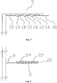
- the lighting system shown consists essentially of three main components, namely a mast 1, a projector unit 2 and a reflector unit 5.
- the projector unit is spaced from the floor or the lower mast end, for example at a height of 3 m, and the reflector unit in turn is above the projector unit , for example at a height of 6 m.
- Thrower unit 2 and reflector unit 5 are separate units which are spatially separated from one another, ie there is an intermediate space between them which separates the two units and runs through the light from the thrower unit to the reflector unit.
- the mast is designed in a conventional manner and can have, for example, a round or square cross section. According to an advantageous embodiment, it accommodates the ballasts for the launcher unit. Power is supplied via a mast connection 6.
- the projector unit consists of several Fresnel mirrors, which are in Fig. 2 are designated by 10 and 12, the mirrors 10 being fixedly mounted and the mirrors 12 being adjustable.
- the mirrors can be pivoted around one, two or three axes and, if necessary, also moved linearly with one, two or three degrees of freedom.
- the mirrors are fixed in place on the edge of the reflector unit 5 and the mirrors 12 can be pivoted inside the reflector unit, so that the permanently mounted mirrors 10 form an outer ring around the adjustable mirrors 12.
- the entire reflector unit consists of 25 mirror elements, 16 of which are fixed mirrors 10 on the edge of the reflector unit 5 and an arrangement of 3 ⁇ 3 adjustable mirrors 12 inside the reflector unit 5.
- Mirrors 10 and 12 are only exemplary.
- the number and / or the arrangement of the stationary and adjustable mirror elements can be different, depending on the respective requirements, just as the reflector unit can consist exclusively of stationary or exclusively of adjustable mirrors.
- the inner, adjustable mirrors have a narrow focusing characteristic and the outer, stationary mirrors 12 generate a wider light distribution than the inner mirrors 12.
- the adjustable mirrors 12 are each assigned a servomotor 14, so that each mirror 12 can be individually pivoted or otherwise adjusted via the servomotor 14 assigned to it.
- the servomotors can advantageously be set via a wired or wireless remote control.
- the pivotable mirrors can be controlled, for example, via a PC. this makes possible a dynamic light distribution that is controlled by a central control unit.
- the LED projector unit 2 is composed of 49 individual modules 20. Each of these modules has an LED 22, a narrow lens 24 assigned to the LED and a heat sink for dissipating the heat generated by the LED.
- the power supply takes place via the mast connection 6.
- the LEDs 22 and the associated lenses 24 are arranged such that the axis of the radiation of all modules 20 is parallel and perpendicular to the light exit surface of the projector unit 2, so that in the in the drawings embodiment shown the light is emitted parallel to the vertical.
- the modules can also be provided to design or arrange the modules so that the axis of the radiation of one or more, possibly also all, modules is inclined against the longitudinal axis of the mast or the vertical, in order to illuminate the To optimally design reflector unit 5.
- the axis of the radiation of individual modules is set at an individual angle or that for a group of such modules the respective axis of the radiation is oriented at the same non-vanishing angle to the vertical, so that the latter Group of modules emit light in the same main direction of radiation.
- the modules can advantageously be arranged adjustably in the launcher unit. It is advantageous if the modules or a corresponding group of modules is assigned a preferably remote-controlled actuator which makes it possible to set or change the angle between the axis of the radiation and the vertical.
Landscapes
- Engineering & Computer Science (AREA)
- General Engineering & Computer Science (AREA)
- Non-Portable Lighting Devices Or Systems Thereof (AREA)
Description
- Die Erfindung betrifft einen Scheinwerfer für Beleuchtungszwecke, insbesondere einen Scheinwerfer zur Verwendung als Werfereinheit in einem Beleuchtungssystem mit indirekter Lichtabgabe, einem sogenannten Sekundärbeleuchtungssystem, sowie ein derartiges Beleuchtungssystem. Derartige Sekundärbeleuchtungssysteme sind für die Innenraumbeleuchtung zum Beispiel aus
EP 0 735 311 A1 und für die Außenbeleuchtung, z.B.EP 0 479 042 A2 bekannt. Bisherige Werferleuchten für Sekundärbeleuchtungssysteme wiesen als Lichtquellen Lampen, z.B. Hochdrucklampen, sowie einen der Lampe zugeordneten Reflektor auf, welcher das Licht der Lampe auf den Reflektor des Sekundärbeleuchtungssystems bündelte. Derartige Werferleuchten waren in der Regel voluminös und in ihrer Bauweise aufwendig. -
US 2005/0162854 A1 offenbart eine lichtemittierende Diode, die mit einer Optik versehen ist, um einen kollimierten Lichtstrahl zu erzeugen. Die Optik umfasst eine Sammellinse in Hauptabstrahlrichtung der LED und einen paraboloiden Reflektor mit zusätzlichen Umlenkreflektoren in Umfangsrichtung der LED. -
DE 20 2004 009 691 U1 offenbart eine Leuchte mit einem LED-Leuchtmittel und einer optischen Einrichtung, die in einem Abstand zum LED-Leuchtmittel im Strahlengang der LED angeordnet ist. Die optische Einrichtung kann ein Reflektor oder eine asphärische Linse sein. Der Abstand zwischen LED und optischer Einrichtung kann entlang der optischen Achse des Systems verstellt werden, um den Öffnungswinkel des erzeugten Strahlkegels zu verändern. - Weitere Beleuchtungseinrichtungen mit LEDs sind in
DE 101 42 582 A1 ,WO 2004/066002 A1 undDE 203 19 107 U1 offenbart. -
US 2005/047153 A1 offenbart einen KFZ-Scheinwerfer mit einer Kurvenlichtfunktion. LEDs innerhalb des KFZ-Scheinwerfers werden entsprechend einem Lenkradeinschlag angesteuert, um eine Kurve auszuleuchten. -
EP 1 568 935 A1 offenbart eine Operationsleuchte, welche mehrere Lichtmodule aufweist, die gegeneinander mit Hilfe gelenkiger Verbindungen verstellt werden können. - Es ist die Aufgabe der Erfindung, eine alternative Konstruktion eines Scheinwerfers zur Verfügung zu stellen, der insbesondere auch als Werferleuchte für ein Sekundärbeleuchtungssystem verwendet werden kann.
- Hierfür stellt die Erfindung einen Scheinwerfer für Beleuchtungszwecke nach Anspruch 1, insbesondere zur Verwendung als Werfereinheit in einem Beleuchtungssystem mit indirekter Lichtabgabe, zur Verfügung, der jeweils eine oder mehrere Lichtquellen aufweist.
- Die Erfindung findet sowohl auf dem Gebiet der Innenraumbeleuchtung und als auch auf dem Gebiet der Außenbeleuchtung Anwendung. Anders als bei Scheinwerfern für andere Zwecke, beispielsweise Kraftfahrzeugscheinwerfern, muß die Lichtabstrahlcharakteristik eines Scheinwerfers für Beleuchtungszwecke an unterschiedlich zu beleuchtende Flächen und unterschiedliche Neigungswinkel zu diesen Flächen angepaßt werden. Vorteilhaft ist daher eine Konstruktion, die einfach an verschiedene Beleuchtungsaufgaben angepaßt werden kann.
- Die Erfindung sieht vor, daß einer oder mehreren LEDs eine Linse zugeordnet ist, welche das Licht der LEDs bündelt und insbesondere ein Strahlbündel erzeugt, bei dem in einer, vorzugsweise jeder Ebene parallel zu der Hauptabstrahlrichtung des Strahlbündels, der Winkel zwischen den Randstrahlen, die das Strahlbündel begrenzen (sogenannter Halbstreuwinkel), zwischen 0° und 20°, vorzugsweise zwischen 0° und 10° liegt. Mehrere Linsen können in einer ein- oder mehrteiligen optischen Einheit zusammengefaßt sein.
- Vorzugsweise ist auf der der Linse gegenüberliegenden Seite der LED ein Kühlkörper zur Abfuhr der von der LED erzeugten Wärme angeordnet.
- Die Erfindung kann vorsehen, daß die Mittelachsen mindestens zweier Strahlbündel, die jeweils über eine einer oder mehreren LEDs zugeordnete Linse abgegeben werden, nicht parallel sind bzw. einen Winkel größer als 0° miteinander einschließen.
- Die Erfindung kann vorsehen, daß LEDs entlang mehreren Linien, insbesondere in mehreren Reihen angeordnet sind, und die Mittelachsen der Strahlbündel, die von den zu den LEDs einer Linie gehörigen Linsen abgegeben werden, parallel zueinander sind.
- Die Erfindung kann vorsehen, daß eine oder mehrere LEDs und/oder eine oder mehrere Linsen, die LEDs zugeordnet sind, verstellbar angeordnet sind, so daß die Orientierung der Mittelachse des jeweiligen Strahlbündels, das von der entsprechenden, einer oder mehreren LEDs zugeordneten Linse abgegeben wird, individuell für jede LED oder gemeinsam für eine Gruppe von LEDs verändert werden kann.
- Die Erfindung kann vorsehen, daß daß die Werfereinheit aus mehreren Modulen zusammengesetzt ist, die jeweils eine oder mehrere LEDs aufweisen.
- Dabei kann vorgesehen sein, daß zwei oder mehr Module unmittelbar miteinander verbunden sind. '
- Die Verbindung kann eine lösbare Verbindung, z.B. eine Steck-, Rast- oder Klemmverbindung, oder eine unlösbare Verbindung, z.B. eine durch Kleben oder Schweißen erzeugte Verbindung sein.
- Weiterhin kann vorgesehen sein, daß eine oder mehrere Module mit einer Steckverbindung miteinander verbunden sind.
- Erfindungsgemäß ist vorgesehen, daß ein oder mehrere Module in dem Scheinwerfer relativ zu anderen Modulen verstellbar angeordnet sind.
- Die Erfindung kann vorsehen, dass ein oder mehrere Module in dem Scheinwerfer relativ zu einer Tragekonstruktion des Scheinwerfers verstellbar angeordnet sind.
- Erfindungsgemäß ist vorgesehen, daß einem oder mehreren dieser Module ein Stellantrieb zugeordnet ist, mit dem das Modul, vorzugsweise ferngesteuert, verstellt werden kann.
- Die Erfindung stellt auch ein Beleuchtungssystem mit einer Werfereinheit, die eine oder mehrere Lichtquellen aufweist, und einer von der Werfereinheit beabstandeten Reflektoreinheit, welche dieser Werfereinheit zugeordnet ist und das Licht der Werfereinheit in einen zu beleuchtenden Raumbereich reflektiert, zur Verfügung, wobei die Werfereinheit ein Scheinwerfer wie vorangehend umschrieben ist.
- Die Erfindung kann vorsehen, daß die Reflektoreinheit einen oder mehrere Fresnelreflektoren aufweist.
- Hierfür können insbesondere solche Fresnelreflektoren verwendet werden, die in
EP 1 411 294 A2 beschrieben sind, auf die hinsichtlich weiterer Einzelheiten verwiesen wird. - Insbesondere kann ein solcher Fresnelreflektor, der mehrere einander nicht überlappende Reflexionsbereiche aufweisen kann, mindestens eine lichtbrechende oder lichtreflektierende Fläche aufweisen, auf der eine lichtlenkende Reflexionsstruktur von Erhebungen und/oder Vertiefungen ausgebildet ist, wobei ein Rand mindestens zweier nicht miteinander verbundener Erhebungen oder Vertiefungen der Reflexionsstruktur jeweils einer Linie folgt, die sich in zwei Dimensionen erstreckt, derart, daß die eine Erhebung bzw. Vertiefung die andere ganz oder teilweise umschließt oder zumindest konkav gegenüber dieser ist.
- Ein solcher Reflektor kann einen Transmissionskörper aus einem lichtdurchlässigen Material, z.B. im Bereich eines oder mehrerer der Reflexionsbereiche, aufweisen, welcher eine Lichteinfallsseite und eine der Lichteinfallsseite gegenüberliegende Seite, sowie eine Reflexionseinrichtung besitzt, welche in den Körper eingetretenes Licht im Bereich der der Lichteinfallsseite gegenüberliegenden Seite in den Körper zurückreflektiert.
- Dabei kann die der Lichteinfallsseite gegenüberliegende Seite des Transmissionskörpers eine Grenzfläche zu einem Licht zumindest teilweise gerichtet reflektierenden Material besitzen.
- Die Grenze eines oder mehrerer Reflexionsbereiche eines solchen Fresnelreflektors kann z.B. gebildet werden durch:
- den Rand oder eine Kante eines Körpers, welcher auf seiner Oberfläche ein oder mehrere Reflexionsstrukturen aufweist und/oder
- einen Bereich eines Körpers, welcher an einer Oberfläche eine oder mehrere Reflexionsstrukturen aufweist, ohne Erhöhungen oder Vertiefungen und/oder
- eine oder mehrere linienförmige Erhöhungen oder Vertiefungen, welche an jeder ihrer beiden Endpunkte durch den Rand eines Körpers oder einen Bereich ohne Erhöhungen und Vertiefungen hinsichtlich der Richtung der Linie, der sie folgen, begrenzt werden.
- Bei einem solchen Reflektor kann ein Rand mehrerer Erhebungen oder Vertiefungen einer Reflexionsstruktur, insbesondere einer oder mehrerer Reflexionsstrukturen eines Reflexionsbereichs, einer Linie folgen, welche der Projektion einer Höhenlinie eines dreidimensionalen imaginären Körpers, dessen Grundfläche mit der Fläche des Reflektors insgesamt oder eines Reflexionsbereichs eines Reflektors identisch ist, auf dessen Grundfläche entspricht.
- Die Reflektoreinheit kann aus einem oder mehreren Reflektoren, insbesondere Spiegeln, bestehen.
- Die Erfindung kann vorsehen, daß die Reflektoreinheit einen oder mehrere ortsfeste Reflektoren und/oder eine oder mehrere verstellbare Reflektoren aufweist.
- Die Erfindung kann vorsehen, daß die ortsfesten Reflektoren am Rand der Reflektoreinheit und die verstellbaren Reflektoren vom Rand der Reflektoreinheit beabstandet angeordnet sind.
- Das erfindungsgemäße Beleuchtungssystem kann mehrere Werfereinheiten aufweisen, die derselben Reflektoreinheit zugeordnet sind.
- Die Erfindung kann eine angetriebene Stelleinrichtung zum Verstellen eines oder mehrerer Reflektoren der Reflektoreinheit vorsehen.
- Die Stelleinrichtung kann insbesondere ferngesteuert sein, z.B. von einem PC.
- Die Erfindung kann insbesondere vorsehen, daß eine oder mehrere LEDs jeweils nur auf einen Reflektor der Reflektoreinheit oder nur auf einen Teil der Reflektoren der Reflektoreinheit, jedoch nicht auf alle Reflektoren der Reflektoreinheit Licht einstrahlen. Insbesondere kann vorgesehen sein, daß bei einer solchen Zuordnung eine oder mehrere der Reflektoren, die einer LED bzw. einer Gruppe von LEDs zugeordnet sind, verstellbar sind und/oder die LED bzw. LEDs und/oder die ihnen zugeordnete Optik und/oder eines oder mehrerer Module, in denen diese LEDs aufgenommen sind, verstellbar sind, so daß die Lichtabstrahlcharakteristik des von dem bzw. den entsprechenden Reflektoren reflektierten Lichts verändert werden kann.
- Die Erfindung kann vorsehen, daß ein oder mehrere Module der Werfereinheit einem oder mehreren Reflektoren der Reflektoreinheit zugeordnet sind, so daß sie Licht nur oder im wesentlichen nur auf diese Reflektoren einstrahlen und auf die anderen Reflektoren der Reflektoreinheit kein oder im wesentlichen kein Licht einstrahlen.
- Die Erfindung kann vorsehen, daß die Werfereinheit und/oder die Reflektoreinheit an einem Mast befestigt sind.
- Die Erfindung kann vorsehen, daß der Abstand zwischen Werfereinheit und Reflektoreinheit 0,2 m bis 6 m, insbesondere 2 m bis 3,5 m beträgt.
- Weitere Merkmale und Vorteile der Erfindung ergeben sich aus der nachfolgenden Beschreibung eines Ausführungsbeispiels der Erfindung anhand der beigefügten Zeichnungen.
- Fig. 1
- zeigt schematisch eine Ausführungsform eines erfindungsgemäßen Beleuchtungssystems,
- Fig. 2
- zeigt Details einer erfindungsgemäßen Reflektoreinheit des Beleuchtungssystems der
Fig. 1 , - Fig. 3
- zeigt Details einer erfindungsgemäßen Werfereinheit in dem Beleuchtungssystem der
Fig. 1 . - Das in
Fig. 1 dargestellte Beleuchtungssystem besteht im wesentlichen aus drei Hauptkomponenten, nämlich einem Mast 1, einer Werfereinheit 2 und einer Reflektoreinheit 5. Die Werfereinheit ist von dem Boden bzw. dem unteren Mastende beabstandet, beispielsweise auf 3 m Höhe, angeordnet und die Reflektoreinheit ihrerseits ist oberhalb der Werfereinheit, beispielsweise in 6 m Höhe, installiert. Werfereinheit 2 und Reflektoreinheit 5 sind separate Einheiten, die räumlich voneinander getrennt sind, d.h. zwischen ihnen befindet sich ein Zwischenraum, der die beiden Einheiten voneinander trennt und durch den Licht von der Werfereinheit zu der Reflektoreinheit läuft. - Der Mast ist in herkömmlicher Weise ausgebildet und kann beispielsweise einen runden oder quadratischen Querschnitt aufweisen. Gemäß einer vorteilhaften Ausfuhrungsform nimmt er die Vorschaltgeräte für die Werfereinheit auf. Die Stromzuführung erfolgt über einen Mastanschluß 6.
- Die Werfereinheit besteht aus mehreren Fresnelspiegeln, die in
Fig. 2 mit 10 und 12 bezeichnet sind, wobei die Spiegel 10 fest montiert sind und die Spiegel 12 verstellbar sind. Die Spiegel können um eine, zwei oder drei Achsen verschwenkt und ggf. auch linear mit einem, zwei oder drei Freiheitsgraden bewegt werden. Bei der dargestellten Ausführungsform sind die Spiegel am Rand der Reflektoreinheit 5 ortsfest und die Spiegel 12 im Inneren der Reflektoreinheit verschwenkbar, so daß die fest montierten Spiegel 10 einen äußeren Kranz um die verstellbaren Spiegel 12 bilden. Bei der dargestellten beispielhaften Ausführungsform besteht die gesamte Reflektoreinheit aus 25 Spiegelelementen, davon 16 ortsfesten Spiegeln 10 am Rand der Reflektoreinheit 5 und einer Anordnung von 3 x 3 verstellbaren Spiegeln 12 im Inneren der Reflektoreinheit 5. Anzahl und Anordnung der in den Figuren gezeigten ortsfesten und verstellbaren Spiegel 10 und 12 ist lediglich beispielhaft. Die Zahl und/oder die Anordnung der ortsfesten und verstellbaren Spiegelelemente kann, je nach den jeweiligen Anforderungen, unterschiedlich sein, ebenso wie die Reflektoreinheit ausschließlich aus ortsfesten oder ausschließlich aus verstellbaren Spiegeln bestehen kann. - Bei dem in
Fig. 1 bis 3 dargestellten Ausführungsbeispiel haben die inneren, verstellbaren Spiegel eine engbündelnde Charakteristik und die außenliegenden, ortsfesten Spiegel 12 erzeugen eine breitere Lichtverteilung als die inneren Spiegel 12. - Gemäß einem vorteilhaften Aspekt der Erfindung ist den verstellbaren Spiegeln 12 jeweils ein Stellmotor 14 zugeordnet, so daß jeder Spiegel 12 über den ihm zugeordneten Stellmotor 14 individuell verschwenkt oder anderweitig verstellt werden kann. Vorteilhafterweise sind die Stellmotoren über eine drahtgebundene oder drahtlose Fernbedienung einstellbar. Die verschwenkbaren Spiegel können beispielsweise über einen PC angesteuert werden. Dies ermöglicht eine dynamische Lichtverteilung, die von einer zentralen Steuereinheit gesteuert wird.
- Die LED Werfereinheit 2 ist aus 49 Einzelmodulen 20 zusammengesetzt. Jedes dieser Module besitzt eine LED 22, eine der LED zugeordnete engbündelnde Linse 24 und einen Kühlkörper zum Abführen der von der LED erzeugten Wärme. Die Stromzuführung erfolgt über den Mastanschluß 6. Gemäß der dargestellten Ausführungsform sind die LEDs 22 und die zugehörigen Linsen 24 so angeordnet, daß die Achse der Ausstrahlung aller Module 20 parallel und senkrecht zu der Lichtaustrittsfläche der Werfereinheit 2 liegt, so daß bei der in den Zeichnungen dargestellten Ausführungsform das Licht parallel zur Vertikalen abgegeben wird. In einer alternativen, nicht dargestellten Ausführungsform kann auch vorgesehen sein, die Module so zu gestalten oder anzuordnen, daß die Achse der Ausstrahlung eines oder mehrerer, ggf. auch aller Module gegen die Längsachse des Masts bzw. die Vertikale geneigt ist, um die Ausleuchtung der Reflektoreinheit 5 optimal zu gestalten. Dabei kann insbesondere vorgesehen sein, daß die Achse der Ausstrahlung einzelner Module in einem jeweils individuellen Winkel eingestellt ist oder auch, daß für eine Gruppe von solchen Modulen die jeweilige Achse der Ausstrahlung in dem gleichen nicht verschwindenden Winkel zu der Vertikalen ausgerichtet ist, so daß diese Gruppe von Modulen das Licht in derselben Hauptabstrahlrichtung abgeben. Vorteilhafterweise können die Module hierbei verstellbar in der Werfereinheit angeordnet sein. Dabei ist es vorteilhaft, wenn den Modulen oder einer entsprechenden Gruppe von Modulen einem vorzugsweise ferngesteuerter Stellantrieb zugeordnet ist, der es ermöglicht, den Winkel zwischen der Achse der Ausstrahlung und der Vertikalen einzustellen bzw. zu verändern.
-
- 1
- Mast
- 2
- Werfereinheit
- 5
- Reflektoreinheit
- 6
- Mastanschluß
- 10
- Spiegel
- 12
- Spiegel
- 14
- Stellmotor
- 20
- Modul der Werfereinheit
- 22
- LED
- 24
- Linse
Claims (16)
- Scheinwerfer für Beleuchtungszwecke mit einer oder mehreren Lichtquellen, der mehrere Leuchtdioden (LEDs) aufweist, wobei einer oder mehreren LEDs (22) eine Linse (24) zugeordnet ist, welche das Licht der LEDs bündelt, wobei der Scheinwerfer aus mehreren Modulen (20) zusammengesetzt ist, die jeweils eine oder mehrere LEDs (22) aufweisen,
wobei ein oder mehrere Module (20) in dem Scheinwerfer relativ zu anderen Modulen verstellbar angeordnet sind, dadurch gekennzeichnet, dass dem einen oder den mehreren Modulen ein Stellantrieb zugeordnet ist, mit dem das Modul ferngesteuert verstellbar ist. - Scheinwerfer nach Anspruch 1, dadurch gekennzeichnet, dass der Scheinwerfer als eine Werfereinheit ausgebildet ist.
- Scheinwerfer nach Anspruch 1 oder 2, dadurch gekennzeichnet, dass ein oder mehrere Module (20) in dem Scheinwerfer relativ zu einer Tragekonstruktion des Scheinwerfers verstellbar angeordnet sind.
- Scheinwerfer nach Anspruch 2 oder 3, dadurch gekennzeichnet, dass zwei oder mehr Module (20) unmittelbar miteinander verbunden sind.
- Scheinwerfer nach einem der Ansprüche 2 bis 4, dadurch gekennzeichnet, dass eine oder mehrere Module (20) mit einer Steckverbindung miteinander verbunden sind.
- Scheinwerfer nach einem der vorhergehenden Ansprüche, dadurch gekennzeichnet, dass die Mittelachsen mindestens zweier Strahlbündel, die jeweils über eine einer oder mehreren LEDs (22) zugeordnete Linse (24) abgegeben werden, nicht parallel sind.
- Scheinwerfer nach einem der vorhergehenden Ansprüche, dadurch gekennzeichnet, dass LEDs (22) entlang mehreren Linien, insbesondere in mehreren Reihen angeordnet sind, und die Mittelachsen der Strahlbündel, die von den zu den LEDs einer Linie gehörigen Linsen (24) abgegeben werden, parallel zueinander sind.
- Scheinwerfer nach einem der vorhergehenden Ansprüche, dadurch gekennzeichnet, dass eine oder mehrere LEDs (22) und/oder eine oder mehrere Linsen (24), die LEDs zugeordnet sind, verstellbar angeordnet sind, so dass die Orientierung der Mittelachse des jeweiligen Strahlbündels, das von der entsprechenden, einer oder mehreren LEDs zugeordneten Linse (24) abgegeben wird, individuell für jede LED oder gemeinsam für eine Gruppe von LEDs verändert werden kann.
- Beleuchtungssystem mit einer Werfereinheit (2), die eine oder mehrere Lichtquellen (22) aufweist, und einer von der Werfereinheit beabstandeten Reflektoreinheit (5), welche dieser Werfereinheit zugeordnet ist und Licht der Werfereinheit (2) in einen zu beleuchtenden Raumbereich reflektiert, dadurch gekennzeichnet, dass die Werfereinheit (2) ein Scheinwerfer nach einem der Ansprüche 1 bis 8 ist.
- Beleuchtungssystem nach Anspruch 9, dadurch gekennzeichnet, dass die Reflektoreinheit einen oder mehrere Fresnelreflektoren (10, 12) aufweist.
- Beleuchtungssystem nach Anspruch 9 oder 10, dadurch gekennzeichnet, dass die Reflektoreinheit einen oder mehrere ortsfeste Reflektoren (10) und/oder eine oder mehrere verstellbare Reflektoren (12) aufweist.
- Beleuchtungssystem nach Anspruch 11, dadurch gekennzeichnet, dass die ortsfesten Reflektoren (10) am Rand der Reflektoreinheit (5) und die verstellbaren Reflektoren (12) vom Rand der Reflektoreinheit (5) beabstandet angeordnet sind.
- Beleuchtungssystem nach Anspruch 11 oder 12, gekennzeichnet durch eine angetriebene Stelleinrichtung (14) zum Verstellen eines oder mehrerer Reflektoren (12) der Reflektoreinheit (5).
- Beleuchtungssystem nach einem der Ansprüche 9 bis 13 mit einem Scheinwerfer nach einem der Ansprüche 5 bis 10, dadurch gekennzeichnet, dass ein oder mehrere Module (20) der Werfereinheit einem oder mehreren Reflektoren (10, 12) der Reflektoreinheit (5) zugeordnet sind, so dass sie Licht im wesentlichen nur auf diese Reflektoren einstrahlen und auf die anderen Reflektoren der Reflektoreinheit im wesentlichen kein Licht einstrahlen.
- Beleuchtungssystem nach einem der Ansprüche 9 bis 14, dadurch gekennzeichnet, dass die Werfereinheit (2) und/oder die Reflektoreinheit (5) an einem Mast (1) befestigt sind.
- Beleuchtungssystem nach einem der Ansprüche 9 bis 15, dadurch gekennzeichnet, dass der Abstand zwischen Werfereinheit (2) und Reflektoreinheit (5) 0,2 m bis 6 m.
Applications Claiming Priority (2)
| Application Number | Priority Date | Filing Date | Title |
|---|---|---|---|
| DE202006004481U DE202006004481U1 (de) | 2006-03-21 | 2006-03-21 | LED-Scheinwerfer und Beleuchtungssystem mit einem solchen Scheinwerfer |
| EP07005834A EP1837590B1 (de) | 2006-03-21 | 2007-03-21 | LED-Scheinwerfer und Beleuchtungssystem mit einem solchen Scheinwerfer |
Related Parent Applications (2)
| Application Number | Title | Priority Date | Filing Date |
|---|---|---|---|
| EP07005834.2 Division | 2007-03-21 | ||
| EP07005834A Division EP1837590B1 (de) | 2006-03-21 | 2007-03-21 | LED-Scheinwerfer und Beleuchtungssystem mit einem solchen Scheinwerfer |
Publications (2)
| Publication Number | Publication Date |
|---|---|
| EP2264362A1 EP2264362A1 (de) | 2010-12-22 |
| EP2264362B1 true EP2264362B1 (de) | 2020-07-29 |
Family
ID=36580748
Family Applications (2)
| Application Number | Title | Priority Date | Filing Date |
|---|---|---|---|
| EP07005834A Active EP1837590B1 (de) | 2006-03-21 | 2007-03-21 | LED-Scheinwerfer und Beleuchtungssystem mit einem solchen Scheinwerfer |
| EP10182275.7A Revoked EP2264362B1 (de) | 2006-03-21 | 2007-03-21 | LED-Scheinwerfer und Beleuchtungssystem mit einem solchen Scheinwerfer |
Family Applications Before (1)
| Application Number | Title | Priority Date | Filing Date |
|---|---|---|---|
| EP07005834A Active EP1837590B1 (de) | 2006-03-21 | 2007-03-21 | LED-Scheinwerfer und Beleuchtungssystem mit einem solchen Scheinwerfer |
Country Status (3)
| Country | Link |
|---|---|
| EP (2) | EP1837590B1 (de) |
| AT (1) | ATE523733T1 (de) |
| DE (1) | DE202006004481U1 (de) |
Families Citing this family (5)
| Publication number | Priority date | Publication date | Assignee | Title |
|---|---|---|---|---|
| DE102006044019B4 (de) | 2006-09-15 | 2011-12-29 | Stiftung Alfred-Wegener-Institut für Polar- und Meeresforschung Stiftung des öffentlichen Rechts | Reflektorstrahler |
| DE202009015359U1 (de) | 2009-11-11 | 2010-03-25 | Caralux Led- Und Neonlichttechnik Gmbh | Beleuchtungseinrichtung für öffentliche Verkehrswege und Plätze mit Lumineszenzdioden als Leuchtmittel |
| DE202015102953U1 (de) | 2015-06-08 | 2015-09-03 | Rudolf Göckel | LED-Lampe |
| DE102019114526A1 (de) * | 2019-05-29 | 2020-12-03 | Bartenbach Holding Gmbh | Leuchte |
| DE102019118285A1 (de) * | 2019-07-05 | 2021-01-07 | Siteco Gmbh | Leuchte mit adaptiver LVK |
Citations (15)
| Publication number | Priority date | Publication date | Assignee | Title |
|---|---|---|---|---|
| US4712167A (en) | 1986-06-30 | 1987-12-08 | Mycro Group Co. | Remote control, moveable lighting system |
| US4811181A (en) | 1988-04-07 | 1989-03-07 | Mycro Group Company | Light fixture bi-directional joint and mounting means |
| EP0735311A1 (de) | 1995-03-31 | 1996-10-02 | Siemens Aktiengesellschaft | Beleuchtungssystem für einen Innenraum |
| DE19600382A1 (de) | 1996-01-08 | 1997-07-17 | Konrad Kotowski | Beleuchtungssystem zur künstlichen Ausleuchtung |
| US5800048A (en) | 1996-03-14 | 1998-09-01 | Musco Corporation | Split reflector lighting fixture |
| DE10005795A1 (de) | 2000-02-10 | 2001-08-23 | Inst Mikrotechnik Mainz Gmbh | Steuerbarer Scheinwerfer |
| WO2001069130A1 (en) | 2000-03-14 | 2001-09-20 | Medinnova Sf | Light system for use especially by operating theatre |
| US6430521B1 (en) | 1999-09-09 | 2002-08-06 | Koito Manufacturing Co., Ltd. | Vehicle headlamp leveling device |
| DE20212282U1 (de) | 2002-08-09 | 2002-10-10 | Automotive Lighting Reutlingen GmbH, 72762 Reutlingen | Kraftfahrzeugscheinwerfer mit mehreren verstellbaren Leuchteinheiten |
| US20050018434A1 (en) | 2003-05-30 | 2005-01-27 | Ronald Giuliano | Positional luminaire |
| US20050047153A1 (en) * | 2003-08-01 | 2005-03-03 | Jean-Paul Ravier | Bending light and dipped beam headlamp for a motor vehicle |
| US20050122737A1 (en) | 2003-12-05 | 2005-06-09 | Koito Manufacturing Co., Ltd. | Headlight |
| EP1568935A1 (de) * | 2004-02-28 | 2005-08-31 | TRUMPF Kreuzer Medizin Systeme GmbH + Co. KG | Operationsleuchte |
| DE102004026160A1 (de) | 2004-05-28 | 2005-12-22 | Siteco Beleuchtungstechnik Gmbh | Beleuchtungssystem zur Erzeugung einer variablen Lichtverteilung |
| WO2006005303A1 (de) | 2004-07-08 | 2006-01-19 | Fraunhofer-Gesellschaft zur Förderung der angewandten Forschung e.V. | Vorrichtung zur konzentration von licht, insbesondere von sonnenlicht |
Family Cites Families (8)
| Publication number | Priority date | Publication date | Assignee | Title |
|---|---|---|---|---|
| DE4031302C2 (de) | 1990-10-04 | 1996-04-11 | Bartenbach Christian | Beleuchtungsanordnung mit einer Lichtquelle und einer optischen Einrichtung |
| DE20009448U1 (de) * | 2000-05-25 | 2000-08-17 | Müller, Markus, 87527 Sonthofen | Beleuchtungsapparat |
| DE10142582B4 (de) * | 2001-08-31 | 2006-10-26 | Signalbau Huber Gmbh | Leuchtmittel-Signalelement, Lichtsignalvorrichtung und Lichtsignalsystem |
| EP1411294B1 (de) | 2002-10-15 | 2011-07-13 | Siteco Beleuchtungstechnik GmbH | Reflektor mit strukturierter Oberfläche, sowie Leuchte und Sekundärbeleuchtungssystem mit einem solchen Reflektor |
| ITMI20030112A1 (it) * | 2003-01-24 | 2004-07-25 | Fraen Corp Srl | Elemento ottico multiplo per un dispositivo di illuminazione a led e dispositivo di illuminazione a led comprendente tale elemento ottico. |
| DE20319107U1 (de) * | 2003-05-16 | 2004-04-15 | Dialight Corp. | Leuchte mit LED-Beleuchtung |
| US7029150B2 (en) | 2004-01-23 | 2006-04-18 | Guide Corporation | Catadioptric light distribution system |
| DE202004009691U1 (de) * | 2004-06-15 | 2004-11-25 | Premier Elektronik Gmbh | Leuchte |
-
2006
- 2006-03-21 DE DE202006004481U patent/DE202006004481U1/de not_active Expired - Lifetime
-
2007
- 2007-03-21 AT AT07005834T patent/ATE523733T1/de active
- 2007-03-21 EP EP07005834A patent/EP1837590B1/de active Active
- 2007-03-21 EP EP10182275.7A patent/EP2264362B1/de not_active Revoked
Patent Citations (15)
| Publication number | Priority date | Publication date | Assignee | Title |
|---|---|---|---|---|
| US4712167A (en) | 1986-06-30 | 1987-12-08 | Mycro Group Co. | Remote control, moveable lighting system |
| US4811181A (en) | 1988-04-07 | 1989-03-07 | Mycro Group Company | Light fixture bi-directional joint and mounting means |
| EP0735311A1 (de) | 1995-03-31 | 1996-10-02 | Siemens Aktiengesellschaft | Beleuchtungssystem für einen Innenraum |
| DE19600382A1 (de) | 1996-01-08 | 1997-07-17 | Konrad Kotowski | Beleuchtungssystem zur künstlichen Ausleuchtung |
| US5800048A (en) | 1996-03-14 | 1998-09-01 | Musco Corporation | Split reflector lighting fixture |
| US6430521B1 (en) | 1999-09-09 | 2002-08-06 | Koito Manufacturing Co., Ltd. | Vehicle headlamp leveling device |
| DE10005795A1 (de) | 2000-02-10 | 2001-08-23 | Inst Mikrotechnik Mainz Gmbh | Steuerbarer Scheinwerfer |
| WO2001069130A1 (en) | 2000-03-14 | 2001-09-20 | Medinnova Sf | Light system for use especially by operating theatre |
| DE20212282U1 (de) | 2002-08-09 | 2002-10-10 | Automotive Lighting Reutlingen GmbH, 72762 Reutlingen | Kraftfahrzeugscheinwerfer mit mehreren verstellbaren Leuchteinheiten |
| US20050018434A1 (en) | 2003-05-30 | 2005-01-27 | Ronald Giuliano | Positional luminaire |
| US20050047153A1 (en) * | 2003-08-01 | 2005-03-03 | Jean-Paul Ravier | Bending light and dipped beam headlamp for a motor vehicle |
| US20050122737A1 (en) | 2003-12-05 | 2005-06-09 | Koito Manufacturing Co., Ltd. | Headlight |
| EP1568935A1 (de) * | 2004-02-28 | 2005-08-31 | TRUMPF Kreuzer Medizin Systeme GmbH + Co. KG | Operationsleuchte |
| DE102004026160A1 (de) | 2004-05-28 | 2005-12-22 | Siteco Beleuchtungstechnik Gmbh | Beleuchtungssystem zur Erzeugung einer variablen Lichtverteilung |
| WO2006005303A1 (de) | 2004-07-08 | 2006-01-19 | Fraunhofer-Gesellschaft zur Förderung der angewandten Forschung e.V. | Vorrichtung zur konzentration von licht, insbesondere von sonnenlicht |
Also Published As
| Publication number | Publication date |
|---|---|
| EP1837590A1 (de) | 2007-09-26 |
| EP1837590B1 (de) | 2011-09-07 |
| EP2264362A1 (de) | 2010-12-22 |
| DE202006004481U1 (de) | 2006-05-24 |
| ATE523733T1 (de) | 2011-09-15 |
Similar Documents
| Publication | Publication Date | Title |
|---|---|---|
| EP2102546B1 (de) | Reflektorstrahler | |
| DE102007035396B4 (de) | Leuchte | |
| DE102007035528B9 (de) | Leuchte | |
| DE202009011500U1 (de) | Optisches System für eine LED-Leuchte | |
| EP2136128A1 (de) | Operationsleuchte | |
| DE102014210500A1 (de) | Optik für eine Fahrzeug-Beleuchtungseinrichtung | |
| WO2011154470A1 (de) | Vorsatzoptik aus transparentem material zum bündeln von licht, linsenarray mit mindestens einer solchen vorsatzoptik und lichtmodul mit einem solchen linsenarray | |
| EP2264362B1 (de) | LED-Scheinwerfer und Beleuchtungssystem mit einem solchen Scheinwerfer | |
| DE102005043992A1 (de) | Signalleuchte für Fahrzeuge | |
| EP3165818B1 (de) | Innen- oder aussenleuchte, insbesondere strassenleuchte, mit verlagerbarer freiformlinse | |
| DE102008033533A1 (de) | Leuchte | |
| DE102017206194A1 (de) | Lichtleiter, Optik, Beleuchtungssytem und Scheinwerfer | |
| EP0735311A1 (de) | Beleuchtungssystem für einen Innenraum | |
| DE102017213103A1 (de) | Beleuchtungssystem und scheinwerfer | |
| DE102017206817A1 (de) | Beleuchtungssystem und scheinwerfer | |
| EP1431158A1 (de) | Signal- und Fahrlichtscheinwerfer für Schienenfahrzeuge | |
| WO2016096608A1 (de) | Led-träger mit einer led und leuchte mit einem derartigen led-träger | |
| DE102017122956A1 (de) | Leuchte | |
| DE202013007715U1 (de) | Leuchte | |
| EP3171077A1 (de) | Blendarme lichttechnik | |
| EP1843086A1 (de) | Reflektorleuchte | |
| EP3086025A1 (de) | Abstrahleinheit für eine operationsleuchte | |
| DE102012215124B4 (de) | Beleuchtungseinrichtung mit mehreren Lichtquellen und Lichtleitkörpern sowie einem Reflektor | |
| EP3671026B1 (de) | Leuchte | |
| DE102011080902A1 (de) | Leuchtenanordnung und leuchteneinheit mit einer leuchtenanordnung |
Legal Events
| Date | Code | Title | Description |
|---|---|---|---|
| PUAI | Public reference made under article 153(3) epc to a published international application that has entered the european phase |
Free format text: ORIGINAL CODE: 0009012 |
|
| AC | Divisional application: reference to earlier application |
Ref document number: 1837590 Country of ref document: EP Kind code of ref document: P |
|
| AK | Designated contracting states |
Kind code of ref document: A1 Designated state(s): AT BE BG CH CY CZ DE DK EE ES FI FR GB GR HU IE IS IT LI LT LU LV MC MT NL PL PT RO SE SI SK TR |
|
| 17P | Request for examination filed |
Effective date: 20110617 |
|
| RAP1 | Party data changed (applicant data changed or rights of an application transferred) |
Owner name: SITECO BELEUCHTUNGSTECHNIK GMBH |
|
| STAA | Information on the status of an ep patent application or granted ep patent |
Free format text: STATUS: EXAMINATION IS IN PROGRESS |
|
| 17Q | First examination report despatched |
Effective date: 20180730 |
|
| GRAP | Despatch of communication of intention to grant a patent |
Free format text: ORIGINAL CODE: EPIDOSNIGR1 |
|
| STAA | Information on the status of an ep patent application or granted ep patent |
Free format text: STATUS: GRANT OF PATENT IS INTENDED |
|
| RIC1 | Information provided on ipc code assigned before grant |
Ipc: F21V 7/00 20060101ALI20200117BHEP Ipc: F21V 14/06 20060101ALI20200117BHEP Ipc: F21V 5/04 20060101ALI20200117BHEP Ipc: F21W 131/10 20060101ALI20200117BHEP Ipc: F21Y 115/10 20160101ALI20200117BHEP Ipc: F21S 6/00 20060101ALI20200117BHEP Ipc: F21V 14/04 20060101ALI20200117BHEP Ipc: F21V 14/02 20060101AFI20200117BHEP Ipc: F21W 131/103 20060101ALN20200117BHEP Ipc: F21S 8/08 20060101ALI20200117BHEP |
|
| INTG | Intention to grant announced |
Effective date: 20200220 |
|
| RIN1 | Information on inventor provided before grant (corrected) |
Inventor name: LEIBIG, JOACHIM Inventor name: LUKANOW, STEPHAN |
|
| RAP1 | Party data changed (applicant data changed or rights of an application transferred) |
Owner name: SITECO GMBH |
|
| GRAS | Grant fee paid |
Free format text: ORIGINAL CODE: EPIDOSNIGR3 |
|
| GRAA | (expected) grant |
Free format text: ORIGINAL CODE: 0009210 |
|
| STAA | Information on the status of an ep patent application or granted ep patent |
Free format text: STATUS: THE PATENT HAS BEEN GRANTED |
|
| AC | Divisional application: reference to earlier application |
Ref document number: 1837590 Country of ref document: EP Kind code of ref document: P |
|
| AK | Designated contracting states |
Kind code of ref document: B1 Designated state(s): AT BE BG CH CY CZ DE DK EE ES FI FR GB GR HU IE IS IT LI LT LU LV MC MT NL PL PT RO SE SI SK TR |
|
| REG | Reference to a national code |
Ref country code: GB Ref legal event code: FG4D Free format text: NOT ENGLISH |
|
| REG | Reference to a national code |
Ref country code: CH Ref legal event code: EP |
|
| REG | Reference to a national code |
Ref country code: DE Ref legal event code: R096 Ref document number: 502007016905 Country of ref document: DE |
|
| REG | Reference to a national code |
Ref country code: CH Ref legal event code: NV Representative=s name: ISLER AND PEDRAZZINI AG, CH |
|
| REG | Reference to a national code |
Ref country code: AT Ref legal event code: REF Ref document number: 1296234 Country of ref document: AT Kind code of ref document: T Effective date: 20200815 |
|
| REG | Reference to a national code |
Ref country code: IE Ref legal event code: FG4D Free format text: LANGUAGE OF EP DOCUMENT: GERMAN |
|
| REG | Reference to a national code |
Ref country code: LT Ref legal event code: MG4D |
|
| REG | Reference to a national code |
Ref country code: NL Ref legal event code: MP Effective date: 20200729 |
|
| PG25 | Lapsed in a contracting state [announced via postgrant information from national office to epo] |
Ref country code: GR Free format text: LAPSE BECAUSE OF FAILURE TO SUBMIT A TRANSLATION OF THE DESCRIPTION OR TO PAY THE FEE WITHIN THE PRESCRIBED TIME-LIMIT Effective date: 20201030 Ref country code: FI Free format text: LAPSE BECAUSE OF FAILURE TO SUBMIT A TRANSLATION OF THE DESCRIPTION OR TO PAY THE FEE WITHIN THE PRESCRIBED TIME-LIMIT Effective date: 20200729 Ref country code: LT Free format text: LAPSE BECAUSE OF FAILURE TO SUBMIT A TRANSLATION OF THE DESCRIPTION OR TO PAY THE FEE WITHIN THE PRESCRIBED TIME-LIMIT Effective date: 20200729 Ref country code: PT Free format text: LAPSE BECAUSE OF FAILURE TO SUBMIT A TRANSLATION OF THE DESCRIPTION OR TO PAY THE FEE WITHIN THE PRESCRIBED TIME-LIMIT Effective date: 20201130 Ref country code: SE Free format text: LAPSE BECAUSE OF FAILURE TO SUBMIT A TRANSLATION OF THE DESCRIPTION OR TO PAY THE FEE WITHIN THE PRESCRIBED TIME-LIMIT Effective date: 20200729 Ref country code: ES Free format text: LAPSE BECAUSE OF FAILURE TO SUBMIT A TRANSLATION OF THE DESCRIPTION OR TO PAY THE FEE WITHIN THE PRESCRIBED TIME-LIMIT Effective date: 20200729 Ref country code: BG Free format text: LAPSE BECAUSE OF FAILURE TO SUBMIT A TRANSLATION OF THE DESCRIPTION OR TO PAY THE FEE WITHIN THE PRESCRIBED TIME-LIMIT Effective date: 20201029 |
|
| PG25 | Lapsed in a contracting state [announced via postgrant information from national office to epo] |
Ref country code: PL Free format text: LAPSE BECAUSE OF FAILURE TO SUBMIT A TRANSLATION OF THE DESCRIPTION OR TO PAY THE FEE WITHIN THE PRESCRIBED TIME-LIMIT Effective date: 20200729 Ref country code: LV Free format text: LAPSE BECAUSE OF FAILURE TO SUBMIT A TRANSLATION OF THE DESCRIPTION OR TO PAY THE FEE WITHIN THE PRESCRIBED TIME-LIMIT Effective date: 20200729 Ref country code: IS Free format text: LAPSE BECAUSE OF FAILURE TO SUBMIT A TRANSLATION OF THE DESCRIPTION OR TO PAY THE FEE WITHIN THE PRESCRIBED TIME-LIMIT Effective date: 20201129 |
|
| PG25 | Lapsed in a contracting state [announced via postgrant information from national office to epo] |
Ref country code: NL Free format text: LAPSE BECAUSE OF FAILURE TO SUBMIT A TRANSLATION OF THE DESCRIPTION OR TO PAY THE FEE WITHIN THE PRESCRIBED TIME-LIMIT Effective date: 20200729 |
|
| REG | Reference to a national code |
Ref country code: DE Ref legal event code: R026 Ref document number: 502007016905 Country of ref document: DE |
|
| PG25 | Lapsed in a contracting state [announced via postgrant information from national office to epo] |
Ref country code: RO Free format text: LAPSE BECAUSE OF FAILURE TO SUBMIT A TRANSLATION OF THE DESCRIPTION OR TO PAY THE FEE WITHIN THE PRESCRIBED TIME-LIMIT Effective date: 20200729 Ref country code: IT Free format text: LAPSE BECAUSE OF FAILURE TO SUBMIT A TRANSLATION OF THE DESCRIPTION OR TO PAY THE FEE WITHIN THE PRESCRIBED TIME-LIMIT Effective date: 20200729 Ref country code: DK Free format text: LAPSE BECAUSE OF FAILURE TO SUBMIT A TRANSLATION OF THE DESCRIPTION OR TO PAY THE FEE WITHIN THE PRESCRIBED TIME-LIMIT Effective date: 20200729 Ref country code: CZ Free format text: LAPSE BECAUSE OF FAILURE TO SUBMIT A TRANSLATION OF THE DESCRIPTION OR TO PAY THE FEE WITHIN THE PRESCRIBED TIME-LIMIT Effective date: 20200729 Ref country code: EE Free format text: LAPSE BECAUSE OF FAILURE TO SUBMIT A TRANSLATION OF THE DESCRIPTION OR TO PAY THE FEE WITHIN THE PRESCRIBED TIME-LIMIT Effective date: 20200729 |
|
| PLBI | Opposition filed |
Free format text: ORIGINAL CODE: 0009260 |
|
| PLAX | Notice of opposition and request to file observation + time limit sent |
Free format text: ORIGINAL CODE: EPIDOSNOBS2 |
|
| 26 | Opposition filed |
Opponent name: SCHOEPF, PATRICK Effective date: 20210429 |
|
| PG25 | Lapsed in a contracting state [announced via postgrant information from national office to epo] |
Ref country code: SK Free format text: LAPSE BECAUSE OF FAILURE TO SUBMIT A TRANSLATION OF THE DESCRIPTION OR TO PAY THE FEE WITHIN THE PRESCRIBED TIME-LIMIT Effective date: 20200729 |
|
| PGFP | Annual fee paid to national office [announced via postgrant information from national office to epo] |
Ref country code: FR Payment date: 20210617 Year of fee payment: 15 Ref country code: DE Payment date: 20210621 Year of fee payment: 15 |
|
| PG25 | Lapsed in a contracting state [announced via postgrant information from national office to epo] |
Ref country code: SI Free format text: LAPSE BECAUSE OF FAILURE TO SUBMIT A TRANSLATION OF THE DESCRIPTION OR TO PAY THE FEE WITHIN THE PRESCRIBED TIME-LIMIT Effective date: 20200729 |
|
| PGFP | Annual fee paid to national office [announced via postgrant information from national office to epo] |
Ref country code: GB Payment date: 20210623 Year of fee payment: 15 Ref country code: CH Payment date: 20210623 Year of fee payment: 15 Ref country code: AT Payment date: 20210618 Year of fee payment: 15 |
|
| PLBB | Reply of patent proprietor to notice(s) of opposition received |
Free format text: ORIGINAL CODE: EPIDOSNOBS3 |
|
| RDAF | Communication despatched that patent is revoked |
Free format text: ORIGINAL CODE: EPIDOSNREV1 |
|
| REG | Reference to a national code |
Ref country code: DE Ref legal event code: R103 Ref document number: 502007016905 Country of ref document: DE Ref country code: DE Ref legal event code: R064 Ref document number: 502007016905 Country of ref document: DE |
|
| PG25 | Lapsed in a contracting state [announced via postgrant information from national office to epo] |
Ref country code: MC Free format text: LAPSE BECAUSE OF FAILURE TO SUBMIT A TRANSLATION OF THE DESCRIPTION OR TO PAY THE FEE WITHIN THE PRESCRIBED TIME-LIMIT Effective date: 20200729 |
|
| REG | Reference to a national code |
Ref country code: BE Ref legal event code: MM Effective date: 20210331 |
|
| RDAG | Patent revoked |
Free format text: ORIGINAL CODE: 0009271 |
|
| STAA | Information on the status of an ep patent application or granted ep patent |
Free format text: STATUS: PATENT REVOKED |
|
| PG25 | Lapsed in a contracting state [announced via postgrant information from national office to epo] |
Ref country code: LU Free format text: LAPSE BECAUSE OF NON-PAYMENT OF DUE FEES Effective date: 20210321 Ref country code: IE Free format text: LAPSE BECAUSE OF NON-PAYMENT OF DUE FEES Effective date: 20210321 |
|
| REG | Reference to a national code |
Ref country code: CH Ref legal event code: PL |
|
| REG | Reference to a national code |
Ref country code: FI Ref legal event code: MGE |
|
| 27W | Patent revoked |
Effective date: 20211009 |
|
| GBPR | Gb: patent revoked under art. 102 of the ep convention designating the uk as contracting state |
Effective date: 20211009 |
|
| REG | Reference to a national code |
Ref country code: AT Ref legal event code: MA03 Ref document number: 1296234 Country of ref document: AT Kind code of ref document: T Effective date: 20211009 |
|
| PG25 | Lapsed in a contracting state [announced via postgrant information from national office to epo] |
Ref country code: HU Free format text: LAPSE BECAUSE OF FAILURE TO SUBMIT A TRANSLATION OF THE DESCRIPTION OR TO PAY THE FEE WITHIN THE PRESCRIBED TIME-LIMIT; INVALID AB INITIO Effective date: 20070321 |
|
| PG25 | Lapsed in a contracting state [announced via postgrant information from national office to epo] |
Ref country code: BE Free format text: LAPSE BECAUSE OF NON-PAYMENT OF DUE FEES Effective date: 20210331 |