EP1411294A2 - Reflektor mit strukturierter Oberfläche, sowie Leuchte und Sekundärbeleuchtungssystem mit einem solchen Reflektor - Google Patents
Reflektor mit strukturierter Oberfläche, sowie Leuchte und Sekundärbeleuchtungssystem mit einem solchen Reflektor Download PDFInfo
- Publication number
- EP1411294A2 EP1411294A2 EP03023538A EP03023538A EP1411294A2 EP 1411294 A2 EP1411294 A2 EP 1411294A2 EP 03023538 A EP03023538 A EP 03023538A EP 03023538 A EP03023538 A EP 03023538A EP 1411294 A2 EP1411294 A2 EP 1411294A2
- Authority
- EP
- European Patent Office
- Prior art keywords
- reflection
- reflector
- light
- area
- depressions
- Prior art date
- Legal status (The legal status is an assumption and is not a legal conclusion. Google has not performed a legal analysis and makes no representation as to the accuracy of the status listed.)
- Granted
Links
- 238000005286 illumination Methods 0.000 claims abstract description 25
- 230000005540 biological transmission Effects 0.000 claims description 24
- 239000000463 material Substances 0.000 claims description 18
- 241000446313 Lamella Species 0.000 description 12
- 238000013461 design Methods 0.000 description 8
- 230000003287 optical effect Effects 0.000 description 8
- 239000011248 coating agent Substances 0.000 description 7
- 238000000576 coating method Methods 0.000 description 7
- 238000010276 construction Methods 0.000 description 4
- 238000005516 engineering process Methods 0.000 description 4
- 230000004048 modification Effects 0.000 description 4
- 238000012986 modification Methods 0.000 description 4
- 238000009826 distribution Methods 0.000 description 3
- 230000000694 effects Effects 0.000 description 3
- 230000008901 benefit Effects 0.000 description 2
- 238000011161 development Methods 0.000 description 2
- 230000006870 function Effects 0.000 description 2
- 238000004519 manufacturing process Methods 0.000 description 2
- 230000005855 radiation Effects 0.000 description 2
- 238000012549 training Methods 0.000 description 2
- 230000002745 absorbent Effects 0.000 description 1
- 239000002250 absorbent Substances 0.000 description 1
- 238000004026 adhesive bonding Methods 0.000 description 1
- 238000000149 argon plasma sintering Methods 0.000 description 1
- 230000015572 biosynthetic process Effects 0.000 description 1
- 238000004140 cleaning Methods 0.000 description 1
- 239000002131 composite material Substances 0.000 description 1
- 239000004020 conductor Substances 0.000 description 1
- 238000011109 contamination Methods 0.000 description 1
- 230000008878 coupling Effects 0.000 description 1
- 238000010168 coupling process Methods 0.000 description 1
- 238000005859 coupling reaction Methods 0.000 description 1
- 230000004907 flux Effects 0.000 description 1
- 230000004313 glare Effects 0.000 description 1
- 239000011521 glass Substances 0.000 description 1
- 238000005304 joining Methods 0.000 description 1
- 238000012423 maintenance Methods 0.000 description 1
- 239000002184 metal Substances 0.000 description 1
- 238000000034 method Methods 0.000 description 1
- 230000000737 periodic effect Effects 0.000 description 1
- 230000000717 retained effect Effects 0.000 description 1
- 238000007493 shaping process Methods 0.000 description 1
- 230000016776 visual perception Effects 0.000 description 1
Images


Classifications
-
- F—MECHANICAL ENGINEERING; LIGHTING; HEATING; WEAPONS; BLASTING
- F21—LIGHTING
- F21S—NON-PORTABLE LIGHTING DEVICES; SYSTEMS THEREOF; VEHICLE LIGHTING DEVICES SPECIALLY ADAPTED FOR VEHICLE EXTERIORS
- F21S6/00—Lighting devices intended to be free-standing
- F21S6/005—Lighting devices intended to be free-standing with a lamp housing maintained at a distance from the floor or ground via a support, e.g. standing lamp for ambient lighting
- F21S6/007—Lighting devices intended to be free-standing with a lamp housing maintained at a distance from the floor or ground via a support, e.g. standing lamp for ambient lighting for indirect lighting only, e.g. torchiere with reflector bowl directed towards ceiling
-
- F—MECHANICAL ENGINEERING; LIGHTING; HEATING; WEAPONS; BLASTING
- F21—LIGHTING
- F21S—NON-PORTABLE LIGHTING DEVICES; SYSTEMS THEREOF; VEHICLE LIGHTING DEVICES SPECIALLY ADAPTED FOR VEHICLE EXTERIORS
- F21S8/00—Lighting devices intended for fixed installation
- F21S8/04—Lighting devices intended for fixed installation intended only for mounting on a ceiling or the like overhead structures
-
- F—MECHANICAL ENGINEERING; LIGHTING; HEATING; WEAPONS; BLASTING
- F21—LIGHTING
- F21V—FUNCTIONAL FEATURES OR DETAILS OF LIGHTING DEVICES OR SYSTEMS THEREOF; STRUCTURAL COMBINATIONS OF LIGHTING DEVICES WITH OTHER ARTICLES, NOT OTHERWISE PROVIDED FOR
- F21V7/00—Reflectors for light sources
- F21V7/0008—Reflectors for light sources providing for indirect lighting
-
- F—MECHANICAL ENGINEERING; LIGHTING; HEATING; WEAPONS; BLASTING
- F21—LIGHTING
- F21V—FUNCTIONAL FEATURES OR DETAILS OF LIGHTING DEVICES OR SYSTEMS THEREOF; STRUCTURAL COMBINATIONS OF LIGHTING DEVICES WITH OTHER ARTICLES, NOT OTHERWISE PROVIDED FOR
- F21V7/00—Reflectors for light sources
- F21V7/04—Optical design
- F21V7/09—Optical design with a combination of different curvatures
-
- F—MECHANICAL ENGINEERING; LIGHTING; HEATING; WEAPONS; BLASTING
- F21—LIGHTING
- F21V—FUNCTIONAL FEATURES OR DETAILS OF LIGHTING DEVICES OR SYSTEMS THEREOF; STRUCTURAL COMBINATIONS OF LIGHTING DEVICES WITH OTHER ARTICLES, NOT OTHERWISE PROVIDED FOR
- F21V11/00—Screens not covered by groups F21V1/00, F21V3/00, F21V7/00 or F21V9/00
- F21V11/06—Screens not covered by groups F21V1/00, F21V3/00, F21V7/00 or F21V9/00 using crossed laminae or strips, e.g. grid-shaped louvers; using lattices or honeycombs
-
- F—MECHANICAL ENGINEERING; LIGHTING; HEATING; WEAPONS; BLASTING
- F21—LIGHTING
- F21V—FUNCTIONAL FEATURES OR DETAILS OF LIGHTING DEVICES OR SYSTEMS THEREOF; STRUCTURAL COMBINATIONS OF LIGHTING DEVICES WITH OTHER ARTICLES, NOT OTHERWISE PROVIDED FOR
- F21V2200/00—Use of light guides, e.g. fibre optic devices, in lighting devices or systems
- F21V2200/40—Use of light guides, e.g. fibre optic devices, in lighting devices or systems of hollow light guides
-
- F—MECHANICAL ENGINEERING; LIGHTING; HEATING; WEAPONS; BLASTING
- F21—LIGHTING
- F21W—INDEXING SCHEME ASSOCIATED WITH SUBCLASSES F21K, F21L, F21S and F21V, RELATING TO USES OR APPLICATIONS OF LIGHTING DEVICES OR SYSTEMS
- F21W2131/00—Use or application of lighting devices or systems not provided for in codes F21W2102/00-F21W2121/00
- F21W2131/10—Outdoor lighting
Definitions
- the invention relates generally to reflectors, and more particularly to reflectors for secondary illumination systems.
- general reflectors where the reflection surface in reflective Individual areas, such as Facets, is decomposed.
- the Reflection surface of a reflector decomposed into a large number of small areas, each specific Have reflection properties.
- a reflection characteristic achieved with a smooth surface is difficult or impossible to achieve.
- it also decomposes the mirror image of the light source into many small points of light, which reduces the glare for a viewer.
- This concerns in particular secondary illumination systems, for example of the type described in EP 0 735 311 A1 or EP 0 479 042 A2 are disclosed.
- the elements of the reflector for redirecting or Widening of the light rays usually consist of convex or concave mirror elements which have a smooth course over their surface without Have discontinuities. Discontinuities occur at most at the interface between mirror elements on.
- the known mirror elements are three-dimensional Elements that are formed either in a metal surface or plastic shaped and provided with a reflective coating. Such structures are disadvantageous because of their uneven surface and their depending on the radius of curvature and Intended use partly large volume, especially in Sekundärbeleuchtungssystemen in the outdoor area forms an increased wind attack surface.
- a reflector in particular a reflector for secondary illumination systems, which has several non-overlapping reflection areas wherein at least a part, preferably each of the reflection areas at least has a refractive or light reflecting surface on which a light directing Reflection area structure is formed by elevations and / or depressions, wherein a Edge of at least two unconnected elevations or depressions of the Reflection area structure follows one line in each case.
- each of these two lines extends in two dimensions; they form So no straight line, but a curved line, a polygon or the like.
- the reflector according to the invention does not necessarily reflect over its entire surface but may also be translucent and / or light wholly or partially absorbent Contain areas.
- the reflector according to the invention does not necessarily have to the only reflector in a lamp, but can interact with other reflectors or a partial reflector of a larger reflector or a part of a larger one form optical component.
- the reflection areas can be wholly or partly in terms of their shape and / or optical Properties be different. Preferably, they can be in visual perception be perceived as separate areas in a reflection of light.
- the invention may in particular provide that the one survey or depression the other either completely surrounds or at least partially surrounds. It can be provided in particular be that one elevation or depression is concave with respect to the other. Under concave in this context is not necessarily a concave curvature but generally a line shape that defines a depression that is not necessarily be smooth, but also points of discontinuity, as in a polygon, can have.
- both Surveys or depressions may be wholly or partially common.
- the outer of the two elevations or depressions limited (or, in the case of more than two elevations or depressions, the outermost one) Structure.
- the invention can also provide that the two elevations or depressions offset from all other elevations or depressions of the reflection area structure are, i. between them and the other elevations or depressions is located always a section of lower or higher levels.
- the reflection area structure is limited to the respective reflection area.
- the reflector consists of a material with one at least partially directed reflecting surface, which in the various areas of reflection as before is structured described.
- the surface is completely reflective, so formed mirroring.
- it can also be designed so that only a part directed by the light and the rest of the light is reflected diffusely, wherein the proportion of the directionally reflected light to the total reflected light according to the preferred embodiments of the invention greater than or equal to 50%, in particular is greater than 70%.
- the appropriate shaping of a homogeneous material can manufacturing technology be problematic.
- the invention can therefore provide that the reflector in the said reflection areas essentially of a body of a moldable Material, e.g. Glass, plastic or the like, which on an outer surface of the reflection region structure and having an outer surface the light incident surface for the Reflection range forms, while the light incident surface or the light incident surface opposite Area with one at least partially, preferably completely directed reflective coating, e.g. a mirroring layer, or, more generally, has an interface with a wholly or partially directed reflective material.
- a moldable Material e.g. Glass, plastic or the like
- a reflector according to the invention can be a transmission body in the region of or several of the reflection areas, in which light can enter and exit and which one Light incident side and one of the light incident side has opposite side, and a Reflection device, which has entered the body light in the field of the light incident side opposite side reflected back into the body.
- the transmission body consists essentially of a translucent material. He can, but does not have to be translucent as a whole, but may also, for example, e.g. by a reflective coating, be designed as a reflector or mirror.
- the invention may provide that the light incident side opposite side of Transmissive body at least in one of said reflection areas an interface to a light wholly or partially directed reflective material has and preferably with a directionally reflective coating, in particular a completely directed reflective coating, is provided.
- the reflective side of the transmission body does not necessarily have to be coated but can also be directly reflective to a voluminous Body adjacent, so that an interface between the translucent material of the Transmissive body and a reflective body is formed. If the the light incident side is structured opposite side of the transmission body, for example also be provided that the wells of the structure with a reflective Material are filled and the level surface thus formed, if necessary, with another Layer is provided of a reflective material, so that in total on the light incident side opposite side creates a smooth surface.
- the invention may provide that the light incident side opposite side of Transmissive body is transparent and on this side a reflective body, preferably with a smooth surface, in particular a directionally reflecting reflector, is provided adjacent to the transmission body, which exiting from this side Reflected light back into the transmission body.
- the reflective body can connect directly to the transmission body or also from this, e.g. be separated by a slight air gap.
- the invention may provide that said reflection region structure on the light incident side the transmission body in at least one reflection region of the reflector is trained.
- the invention may provide that the reflection region structure in at least one reflection region is formed on the light incident side opposite side.
- the invention may provide that the reflection area structure in a translucent Surface is formed and acts refractive.
- the invention may provide that the light incident side opposite side of Transmissive body in at least one reflection region, the said reflection region structure has and completely reflective, in particular fully directed reflective is.
- the invention may provide that the light incident side of the transmission body in at least a reflection region, preferably all reflection regions, is smooth.
- This embodiment of the invention has the particular advantage that the light incident surface the reflector is completely smooth, which makes these insensitive to pollution and mechanical Makes actions and facilitates the cleaning.
- the for the optics of the reflector important reflection area structure protected by that is located on the inside of the transmission body.
- the invention can provide in particular that the transmission body on a support plate is arranged. This gives the reflector stability and protects at the same time from the Light incident side of the transmission body side facing away. This is especially true advantageous if the structured side of the transmission body from the light incident side turned away.
- the light-conducting body is directly adjacent to the support plate.
- the light-conducting body on the sides of the support plate or enclosing a housing such that each may pass through the reflective area structure Conditional space between the support plate and the transmission body after is completed on the outside.
- the invention may provide that one or more reflection areas wholly or partly bounded by the edge or edge of a body which is on its surface contains one or more reflective area structures.
- the invention may provide that one or more reflection areas wholly or partly by a portion of a body having on one surface one or more reflective area structures having limited, which no elevations or depressions and transverse to the lines of the ridges or the soles of elevations or depressions the associated reflection area structure runs and these elevations or depressions Limited in length.
- the invention may provide that one or more areas of reflection by the edge of a self-contained increase or depression are limited.
- the invention may also provide that one or more, in particular all reflection ranges each formed on the surface of each of a body, wherein the or the corresponding bodies each have only this one reflection region and wherein the boundaries of the reflection range in this case, preferably with the edge of the surface of this body, which forms the reflection area, coincide.
- the invention may provide that an edge of at least two elevations or depressions each follows either a closed line or together with the edge of the reflection area forms a closed line, such that the one elevation or depression the other either alone or together with the edge of the reflection area completely surrounds. It may be provided in particular that the enclosed survey or depression is limited in part by the said closed line. For example can limit the enclosed elevation or depression to the edge of the reflection area, which, together with the edge of the elevation or depression, forms the closed line, which surrounds the survey or depression.
- the invention may provide that an edge of a plurality of elevations or depressions of a or a plurality of reflection area structures follows a line, which is the projection of a Height line of a three-dimensional, preferably convex or concave curved imaginary Body whose base is identical to the surface of the reflection area, on whose base area corresponds.
- the invention can provide that the reflection areas with respect to the two-dimensional Shape of their edge (not necessarily with regard to the structure formed on them elevations and / or depressions) are uniform or at least several Refelxions Stude the same two-dimensional shape of its edge, especially the same Outline shape and the same size.
- the reflection areas with respect to the two-dimensional Shape of their edge are uniform or at least several Refelxions Stude the same two-dimensional shape of its edge, especially the same Outline shape and the same size.
- it can be provided that it too Any two-dimensional shape of a reflection area or at least for several different two-dimensional shapes or the majority thereof, in the reflector more Reflection areas are, which have this shape.
- the same structure of elevations and / or depressions to be available.
- any structure of surveys and / or depressions but at least to several such structures or the predominant Part thereof, each having a plurality of reflection areas having this structure, this structure being the same or, according to an alternative embodiment, can be oriented differently.
- the reflection areas have different structures or structures with the same topology but different Have orientation.
- the openings that intervene between the Endpoints of the line are defined, in a reflection area in another direction as in a different area of reflection, although the lines themselves are within the range of reflection have the same topology.
- the ratio of the two Be reflective areas such that the one reflection area by a rotation of the other Reflection range can be generated.
- the invention may provide that for at least two elevations or depressions, respectively one edge that is not identical to one edge of the other well, on a portion an imaginary closed line runs, with one of the two imaginary closed lines completely encloses the other and where the sub-area on which the edge of each survey or depression runs, in each case by neighboring Intersections is defined with a third imaginary closed line (borderline), which intersects the first and second closed imaginary lines.
- This third imaginary In a sense, line forms a frame with which that section of the two imaginary ones closed lines, which in the reflection area structure in the form of a survey or Recess is to be implemented, is cut out.
- the third imaginary closed In particular, line may coincide with the boundary of a reflection range.
- the invention may provide that several, preferably all elevations and / or depressions a reflection area structure are closed in themselves or at their ends in the Edge of the reflection area open.
- the invention may also provide that the reflection area structure has a central portion which is bounded on all sides by a survey or depression, and the reflection area structure outside this central area is entirely made up of elevations and recesses, which are separated from each other and each one closed Follow line or a line that opens at their ends in the edge of the reflection area and forms a closed line together with the edge of the reflection area, wherein each of these elevations and depressions alone or together with the edge of the reflection area enclosing the central area and each of these elevations or depressions of all surveys or recesses that are outside the area enclosed by it located on all sides that do not coincide with the edge of the reflection area, is enclosed.
- the invention may also provide that a reflection area structure has a marginal area which is on those sides where it does not pass through the edge of the reflection area is limited by a separate collection or depression and the reflection area structure outside of this edge area entirely from elevations and recesses, which are separated from each other and each of a line, the opens at their ends in the edge of the reflection region and together with this one closed line forms follow, with each of these elevations or depressions together enclosing said edge region with the edge of the reflective region and each These surveys or depressions of all surveys or wells that are outside of the area enclosed by it, on all sides together with the Enclosed edge of the reflection area.
- the invention may provide that in a reflection region structure Survey or depression completely outside that of another survey or depression enclosed or enclosed area lies. It can be provided in particular be that the survey or depression that a second survey or depression completely or partially encloses or at least concave against this and with this second survey is not connected, outside of that range, which by this elevation or depression and an imaginary straight line representing the two endpoints the second survey or depression connects, is included.
- the second survey or depression, which according to the invention is completely or partially enclosed by a first survey or depression or with respect to which the first bump is concave, within that range which is due to this first elevation or depression and an imaginary straight line, which connects the two endpoints of the first survey or depression, included becomes.
- the invention may provide that the elevations and / or depressions outside the Central region or edge region at least partially concentric and / or parallel to each other are.
- the invention may provide that the lying outside of the central region or edge region Elevations and / or depressions at least partially have a circular shape.
- these surveys or depressions also have another closed geometric shape, e.g. that of an ellipse, a square, a rectangle or other polygon or the like, or the shape of a Have a subsection of this.
- the invention can provide that the central area or edge area to the outside has concave or convex curved surface.
- this reflection area structure When the said reflection area structure is formed in a light-reflecting surface is and this light-reflecting surface forms the light incident side of the reflector, this is Surface preferably convexly convex towards the outside. If this reflective surface of the Light incident surface opposite surface of a transmission body, it is preferably to the outside concave (ie convex to the light incident side).
- the invention may provide that the elevations and / or depressions outside the Central region or edge region in a cross-section perpendicular to the direction of the line, which follows the survey or depression, are formed like a jag.
- the said reflection region structure of the structure a Fresnel lens corresponds.
- the refractive reflection region structure does not have to be a Fresnel lens act, i. be formed in a transparent interface of a body. she can be formed in a reflective surface so that it forms a reflector, the is structured similar to a Fresnel lens.
- the thickness of the reflector opposite a conventional facet structure can be reduced and at the same time the reflection properties a facet structure are essentially retained.
- constructive can be a facet structure of a known type in a reflector structure according to the invention by making the facet substantially more uniform in layers on the one hand Thickness and on the other hand in (not necessarily circular cylindrical) cylinder sections perpendicular to the base of the facet whose base is defined by the intersecting line of the bottom or top Top of a layer is defined with the surface of the facet divided and in each this cylinder sections maintains only the top of the layers and at the base level the facet orders.
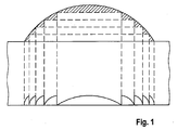
- This principle is illustrated schematically in FIG. Precautionary will be on it indicated that Fig.
- the reflection properties of the reflection region structure substantially the reflection properties correspond to the original facet.
- the invention may provide that the height of the elevations of the reflection area structure, in relation to a parallel to a smooth imaginary or real surface, which is an envelope the light incident surface forms in a reflection region, at least predominantly have the same height.
- feature sizes are within a range of 0.1 mm to 10 mm proved to be advantageous.
- the dimensions of the reflection areas can, especially in applications for secondary illumination systems, in a range from 40 mm x 40 mm to 4000 mm x 4000 mm, in particular 40 mm x 40 mm to 350 mm x 350 mm, according to certain embodiments from 40mm x 40mm to 150mm x 150mm, in another embodiment about 300 mm x 300 mm, lie.
- the reflection areas are square and in this case the preceding measures indicate both the area and the edge length
- the reflection areas may also have other shapes, eg a rectangular shape, a hexagon shape, the shape of a circle segment or the shape of a ring or ring portion
- the area of these areas is equal to the area implied by the preceding measures, and thus, according to certain embodiments, may be in the range 16 x 10 2 mm 2 to 16 x 10 6 mm 2 .
- the reflector or partial sections of the reflector can be flat. This is especially true at advantageous for use in secondary illumination systems.
- the reflector or sections however, in certain embodiments, the reflector may also be curved or otherwise shaped.
- a reflector according to the invention can be constructed from a plurality of reflection regions which directly adjoin one another and preferably regularly, similar to a faceted reflector, are arranged.
- the individual reflection areas can be like facets Act. In particular, in reflection, they may be present in at least some, preferably all Viewing directions as individual light sources act, each on the respective Reflection range appears limited.
- the reflection region structure in a or repeats two directions periodically, with the reflection area structures adjacent Reflection areas can also be directly adjacent to each other.
- the invention can provide that at least a part of the reflection areas respectively a transmission body are defined which has exactly one reflection area structure has at least two unrelated elevations or depressions, of where the one at least partially surrounds the other and / or is concave to this.
- the single ones Transmissive bodies can be interconnected. You can e.g. be integrally formed with a connecting them supporting portion of the reflector.
- the reflector can be structured in a facet-like manner, the reflection areas each correspond to a facet, except that in this case the facets of the reflector not with a curvature, but with the above-described reflection area structure are provided.
- the invention may provide that the reflection ranges are defined by a Body of translucent or opaque material on a surface several reflection area structures of elevations and depressions are provided, which have at least two separate elevations or depressions, one of which at least partially surrounds and / or is concave with the other, wherein each of the reflective area structures over other reflective area structures is limited by a preferably self-contained elevation or depression, which is separate from other surveys or wells.
- the reflection areas are at least partially through the outline the respective reflection area structure limited and thus defined. Because the outer Elevation or depression that limits the range of reflection, other surveys or depressions does not cross or merge with them, but at best their edge possibly coinciding with an edge of a neighboring elevation or depression, the corresponding reflection area of the reflector is clearly delimited. When the reflection area structure has several self-contained elevations or depressions, which surround each other, the outermost of these elevations or depressions sets the edge of the Reflection range fixed. Conversely, in this embodiment, if the limiting Survey or depression is closed, no survey or depression of a reflection area an elevation of the reflection area structure of another Enclose reflection area in the sense of a closed line, crossing it or in these lead to.
- the invention may also provide that a plurality of on the surface of a body Reflection areas are realized with different reflection area structures.
- the body as a whole can form the reflector or part of a larger, more than one be such body composite reflector.
- the invention provides in particular reflectors, which are used for lighting tasks be used, in which at least in certain directions light fluxes of more than 1000 lumens are emitted, and in particular also lights or lighting systems for such lighting tasks available, in which one or more Light sources cooperate with a reflector according to the invention.
- Lighting tasks that be solved with a reflector according to the invention or a lamp according to the invention can, in particular, space illumination, street lighting, facade radiation or a combination of these three applications, furthermore free-form illumination, Roundabout illumination or spot illumination.
- a particularly advantageous application of the invention in secondary lighting systems in particular if the reflector of the secondary illumination system is planar is, as well as generally lighting arrangements with a reflective component and a light emitting component, which are separated from each other.
- the invention provides a secondary illumination system with a light source and a reflector spaced from the light source and emitting the light emitted from the light source Light reflected in a room area to be illuminated, available which characterized in that the reflector is formed as described above.
- the secondary reflector of the secondary illumination system can be mounted on a ceiling a room arranged or suspended from the ceiling, while a thrower lamp formed light source near the ground or sunk in the ground or at least spaced from the ceiling.
- the secondary reflector can also be attached to a frame or attached to a mast, wherein in a lower region of the mast or frame, offset from the secondary reflector, e.g. by 1 to 15 meters or more, one or more launchers are arranged as light sources.
- the distance between the light source of the secondary illumination system, which in particular can be a projector light, and the reflector between 0.1 m and 50 m with distances of about 0.1 m to 3 m, especially in the interior lighting area be used while larger distances, such as Distances of 3 m or more, especially in outdoor areas will be used.
- larger distances than 3 m can occur even at high internal spaces, while in outdoor lights, where the launcher attached to the end of a mast is, the distance from the reflector are quite in the range of 0.1 m to 1 m can.
- the invention is not limited to the use of such reflectors in secondary lighting systems limited, but can in particular also with direct-radiating Lights are used, especially as a roof or side wall reflector in lights with lateral light coupling, optionally in conjunction with a refractive Structure at or near the light exit surface, or in conventional lights, at where the light source is arranged in a reflector. In the latter case, in particular be provided that one, several or all sides of the reflector in whole or in part are just. Because the light-directing properties of the reflector through the structure of elevations and / or depressions are determined and not by a specific curvature the side wall, it is according to the invention not necessary, curved reflector walls to use as they are otherwise commonly used. This will increase on the one hand the design possibilities. For example, you can shine with a four-pronged, Hexagonal, octagonal or otherwise polygonal light exit surface with inventive produce flat reflectors, which have similar properties as conventional have round lights with a curved reflector.
- the production is simplified because it is possible with basically the same Structure of the reflector by different plane reflector elements different Achieve light-emitting properties.
- a plurality of inventively embodied reflectors are included, which together form a luminaire reflector and optionally also interchangeable.
- a series of lights with the same basic structure, in particular with the same structure of the reflector, to realize that only by a different Distinguish structuring of the reflector surface.
- An inventive reflector or a luminaire according to the invention can in particular a shielded light distribution, for example for computer workstations (BAP), produce a low-beam or wide-beam light distribution.
- BAP computer workstations
- the invention is generally applicable to optical reflective luminaire components.
- the effect of a lighting grid with reflective Slats are obtained by a body with reflective and translucent sections is provided, the lamellae of a grid or the spaces between correspond to the fins, so for example strip-shaped reflective areas, the correspond to the slats and which also strip-shaped light-transmitting areas alternate, which correspond to the spaces between the slats.
- This sequence of stripe-shaped translucent and reflective sections supplemented by a frame-shaped, surrounding these sections reflective area which is the side reflectors in a luminaire with a grid or side reflectors corresponds to the grid.
- the reflective areas can be used as reflectors Elevations and / or depressions formed in the manner described above be that emulate the reflection effect of the slats or the side reflectors.
- the invention also provides a reflector having one or more areas of reflection each having at least one refractive or light-reflecting surface, on the a light-guiding reflection area structure of elevations and / or depressions is formed, wherein at least one reflection region or a combination of a plurality of reflection regions at least approximately the reflection properties of a Wall, in particular a side wall of a lamella, in particular a three-dimensional Lamella having.
- the reflector can also have two opposite sides, each are provided with one or more reflection regions according to the invention, which at least approximately the reflection properties of opposing each other Have side walls of a lamella. It can also be provided in particular that the Reflector is designed three-dimensional and next to the two side walls and a Has roof wall, wherein the side walls and optionally the roof wall in accordance with the invention Mann are designed such that they the reflection properties of a corresponding Slat at least approximately.
- the one or more reflection areas which the Have reflective properties of a wall of a lamella, of a Fresnel construction the lamella, as illustrated in Figure 1 and has been explained above.
- the reflection area structure or the reflection area structures which emulate the lamella, parallel elevations and / or depressions, contains concentric circular or arc sections or the like.
- the reflector in one or more reflection regions, which emulate the properties of a wall of a lamella, is made of a translucent material and on a surface with an inventive Structure is provided, being adjacent to this structured surface or her or on the opposite surface a reflective layer or a reflective one Body is present, in particular a specularly reflective layer.
- the reflective Layer can be spaced from the structured surface and through the translucent Material to be separated.
- the invention can be a surface of a translucent body structure and mirror this surface or the opposite surface.
- a plurality of reflectors or combinations of reflectors, each emulating a blade, spaced from each other are.
- These reflectors or combinations of reflectors can transparent areas are separated from each other, in particular from the same base material how the base material of the reflectors can be made.
- each having optical properties similar or identical to those of a lamella, a side reflector and / or others Have components of a grid and to assemble a reflector arrangement from these parts, which in terms of their optical properties of a conventional grid corresponds and in particular has parts or sections which, in terms of their optical Properties correspond to lamellae, and / or parts or sections which, in terms of their optical properties side reflectors of a grid or other components of a Rasters correspond.
- the structures which define the reflection regions according to the invention can be used with respect to their diameter, their shape and also with regard to the curvature of the elevations or depressions vary. There are both symmetrical structures and structures possible, which go back to free-form surfaces (see Fig. 1).
- the invention is based on the surprising finding that the conventional facet elements, which require a relatively large volume and training in three dimensions, can be replaced by a flatter structure, which is essentially on a two-dimensional Basic structure is based along which formed elevations and depressions become. This results in a lower weight and, when used outdoors, a lower windage area. At the same time, this also opens up the advantageous possibility to design the reflector so that it is less susceptible to contamination and easier to clean.
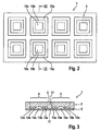
- the reflector has a base plate 5, which essentially serves as a support plate and intended to give stability to the whole structure. In the illustrated embodiment this support plate 5 has no optical function.
- a Body 7 made of a translucent material, e.g. by gluing or by a mechanical Attachment attached, which has a smooth surface 9 on the of the support plate. 5 opposite side and a textured surface 11 on the support plate 5 facing Side has.
- recesses 13a to 13c and 15a to 15c are formed (see Fig. 3), each having a substantially vertical inwardly facing wall and have a curved outwardly facing wall.
- depressions are in Fig. 2 with indicated by solid lines.
- the surface 11 is mirrored.
- the Surface 11 also be mirrored. However, it may be desirable to straighten in area 11 To bring about no reflection to the individual areas 3 optically stronger from each other to separate.
- the surface 11 or the opposite surface of the support plate 5 provided in this area 17 with a light-absorbing or light-scattering coating.
- the surface 9 forms the light incident surface of the reflector. Light, which is on this surface is incident, enters the body 7 and is at the interface in the region of the recesses 13a to 13c and 15a to 15c reflected so that it exits at the surface 9 again.
- the recesses 13a to 13c and 15a to 15c according to the design principle shown in Fig. 1 designed to be shaped like a three-dimensional curved surface, e.g. one Kugelkalotte, act.
- the drawings neither to scale nor the shape of the recesses 13a to 13c and 15a to 15c Realistic is reproduced. These were shown only schematically for illustration.
- the reflector 1 acts like a faceted reflector with spherical caps, as in Fig. 1 are shown. Unlike a dome reflector, however, it has a smooth surface 9 and can be made much flatter.
- the plate 7 has a thickness in a range of 0.1 mm to 5 mm. This leads to correspondingly flat reflector walls.
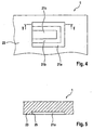
- Fig. 4 shows a modification of the reflection area structure in which the outer recesses do not have a closed shape.
- the wells here designated 21a and 21b, which correspond to the recesses 13a and 13b and 15a and 15b have in this embodiment a horseshoe shape whose open side leads to an unstructured area 23 has. It can be seen from the cross section of Fig. 5 that each of the recesses 21 a and 21b on the unstructured area 23 adjacent side of a vertical wall 25th is limited. In the direction perpendicular to the line V-V corresponds to the cross section of Structure that of the recesses 13a and 13b of Fig. 3.
- the area 21c may be a Have maximum in its interior, as is the case with the recess 13c, or else have its maximum at the edge adjacent to the unstructured region 23.
- the body 5 can be located both on the light incident surface 9 as well as at the light incident surface opposite side with a Be provided structure that acts refractive or light-reflecting.
- the surface 11 is not is mirrored and the support plate 5 completely or in the region of the structures 13a to 13c and 15a is formed to 15c mirrored. It could also be provided that the area of the depressions 13a to 13c and 15a to 15c with a reflective material by volume is filled, so that a smooth interface with the support plate 5 is formed.
- a secondary illumination system may have a structure which is identical to the structure which is e.g. in EP 0 735 311 A1 or EP 0 479 042 A2 and is shown, to which reference is made for further details, wherein only the secondary reflector in the invention described above Way is formed.
- a launcher and a distance from the projector light arranged secondary reflector which is formed according to the invention on.
- the various individual reflectors formed in the manner according to the invention be or even each reflection areas in a reflector according to the invention correspond.
- individual reflectors or units can be adjusted with several individual reflectors. According to a possible embodiment These individual reflectors or such units may also be interchangeable, so that they in place, depending on the desired Lichtabstrahl characterizing be used can be used to create a specific illumination distribution.
- Figs. 6 to 8 illustrate embodiments of such secondary illumination systems.
- a secondary lighting system is designed as a table lamp, wherein the reference numeral 30 a table, the reference numeral 32 a projector light, the reference numeral 34th a reflector according to the invention and the reference numeral 36 denotes the illuminated surface.
- the distance between the projector light 32 and the reflector 34 be 0.1 m to 0.5 m.
- Fig. 7 shows a secondary lighting system in which below a ceiling 40, a projector light 42 is mounted, which light on a reflector designed according to the invention 44, which reflects the light to the adjacent wall, the reference numeral 46 denotes the illuminated area.
- Fig. 8 shows an application example in the outdoor lighting area.
- the reference numeral 50 denotes while a mast, the reference numeral 52 denotes a projector light and the reference numeral 54 denotes a reflector according to the invention, which detects the light emitted by the projector light 52 is irradiated to him, reflected in different areas.
- FIG. 8 various lighting tasks are illustrated with the inventive Reflector can be solved.
- the area marked A denotes the illumination a street, so the lighting of a strip-shaped elongated terrain section.
- the area labeled B illustrates the illumination of a square and the one labeled C.
- Area illustrates the lighting of a facade.
- suitable reflective structures or by the use of different Structures in different areas of reflection several lighting tasks, about two or more of the lighting tasks illustrated in FIG. 8, simultaneously to be solved.
- FIG. 8 in connection with a space illumination by a suitable design of the reflector can be achieved that the area around the mast is relatively dark and illuminates an annular portion around this dark area is.
- a given lighting task can be the corresponding reflector structures calculated by known methods, such as ray tracing.
- Another design option For example, in the center of the reflector 54 would be a Fresnel reflector which emulates a convex spherical reflector, in which case it is However, stronger than a ball reflector is possible, light rays that with a small Tilt angle to the mast 50 incident on the reflector 54, at a relatively large angle to reflect on this mast.
- FIG. 9 shows a schematic cross section of a luminaire according to the invention, which has a light guide 60, in the light from light sources 62, in particular from the sides Lamps, is coupled.
- the light guide 60 has a cavity 64, a reflector 66 and optionally side reflectors 68 and can on his the roof reflector 66 opposite side by a translucent cover 70, for example a translucent plate, be completed.
- the lamps 62 are preferably Einkoppelreflektoren 72 assigned to the lamps facing away from the light conductor 60 on the Surround side and the light incident on them preferably completely in the light guide 60, i. into the cavity 64, to the reflectors 66 or 68, or directly to the cover 70 reflect.
- the cover 70 may be provided with a refractive light-directing Be provided structure, as described for example in EP 1 065 436 A1 (EP 99 125 646.2) or EP 1 106 916 A2 (EP 00 126 203.9) is described. It can also refractive, light-directing Structures may be provided, as described in EP 0 846 915 A1 for generating a shield No. 5,555,109 and US Pat. No. 5,396,350, respectively for more details regarding the corresponding structures.
- At least one of the reflectors 66 or 68 is in the according to the invention, as described above, designed.
- the Roof reflector 66 may be configured so that it substantially the radiation to a specific Angular range, based on a perpendicular to the light exit surface, limited.
- Fig. 10 shows schematically an embodiment of a lamp in which a lamp 90 via a reflector assembly 92 is arranged.
- the reflector assembly 92 includes individual reflectors 94, which each have planar side walls, which in the above-described Are structured so that they the reflection properties of the side walls of a Raster lamella, possibly also the roof wall of a grid lamella, emulate. Between the reflectors 94 are, as in a normal grid, translucent areas, which may be free spaces between the reflectors 94, for example. In Fig. 10 are only to recognize the narrow sides of the reflectors 94, but not the erfindunsdorfe structured Side walls.
- FIG. 10 can be supplemented by a further circulating planar reflector which, in accordance with the invention, for example by a Fresnel construction, is structured so that it the reflection properties of the side reflectors of a grid emulated.
- This reflector surrounds, as in a normal grid, the reflectors 94, which the lamellae, but with the difference that this frame-like reflector on its reflection surfaces, apart from the elevations and depressions which the Form structure on its surface, is even.
- the invention is not limited to reflectors for secondary illumination systems, but Rather, it also finds application in all areas where faceted reflectors, in particular with facets in dome shape, to be used. In the concrete lighting technology Application therefore does not necessarily have to separate the light source from the reflector but can also be arranged in this.
- FIG. 12 illustrates a lamp in which a lamp 100 is disposed within a reflector, which consists of three planar reflector sections 102, 104 and 106 is constructed, which are each formed in the manner according to the invention. It would also be conceivable to design only one or two of these reflector sections according to the invention and leave the remaining reflector (s) unstructured.
- Fig. 12 is schematically sketched a fluorescent lamp. However, it is also possible a different lamp or to use other reflector geometries.
Landscapes
- Engineering & Computer Science (AREA)
- General Engineering & Computer Science (AREA)
- Optical Elements Other Than Lenses (AREA)
Abstract
Description
- den Rand oder eine Kante eines Körpers, welcher auf seiner Oberfläche ein oder mehrere Reflexionsbereichsstrukturen aufweist und/oder einen Bereich eines Körpers, welcher an seiner Oberfläche eine oder mehrere Reflexionsbereichsstrukturen aufweist, ohne Erhöhungen oder Vertiefungen und
- eine oder mehrere linienförmige Erhöhungen oder Vertiefungen, welche an jeder ihrer beiden Endpunkte durch den Rand des Körpers oder den Bereich ohne Erhöhungen und Vertiefungen hinsichtlich ihrer Längsrichtung begrenzt wird.
- Fig. 1
- ist eine schematische Darstellung, welche das Prinzip der Konstruktion einer erfindungsgemäßen Struktur illustriert.
- Fig. 2
- zeigt schematisch eine Reflektorfläche gemäß der Erfindung in einer Draufsicht.
- Fig. 3
- zeigt schematisch einen Querschnitt entlang der Linie III-III in Fig. 2.
- Fig. 4
- zeigt schematisch eine Abwandlung der Struktur der Reflexionsbereiche gemäß Fig. 2 auf einem Teilabschnitt des Reflektors.
- Fig. 5
- zeigt einen Querschnitt entlang der Linie V-V in Fig. 4.
- Fig. 6
- zeigt eine Realisierung einer erfindungsgemäßen Leuchte als Tischleuchte.
- Fig. 7
- zeigt schematisch die Realisierung einer erfindungsgemäßen Leuchte als Deckenleuchte,
- Fig. 8
- zeigt ein Anwendungsbeispiel bei einer Außenleuchte, wobei verschiedene Beleuchtungsaufgaben illustriert sind,
- Fig. 9
- zeigt schematisch eine Ausführungsform einer erfindungsgemäßen Leuchte mit einem Lichtleiter, die einen erfindungsgemäß ausgestalteten Reflektor aufweist,
- Fig. 10
- zeigt ein schematisches Anwendungsbeispiel von erfindungsgemäßen Reflektoren zur Verwendung anstelle eines Leuchtenrasters.
- Fig. 11
- zeigt schematisch eine weitere mögliche Ausführungsform einer erfindungsgemäßen Leuchte.
Claims (29)
- Reflektor, insbesondere Reflektor für Sekundärbeleuchtungssysteme, welcher mehrere einander nicht überlappende Reflexionsbereiche (3) aufweist,
wobei zumindest ein Teil der Reflexionsbereiche (3) mindestens eine lichtbrechende oder lichtreflektierende Fläche (11) aufweist, auf der eine lichtlenkende Reflexionsbereichsstruktur von Erhebungen und/oder Vertiefungen (13a, 13b, 15a, 15b; 21a, 21b) ausgebildet ist, wobei ein Rand mindestens zweier nicht miteinander verbundener Erhebungen oder Vertiefungen (13a, 13b, 15a, 15b; 21a, 21b) der Reflexionsbereichsstruktur jeweils einer Linie folgt, die sich in zwei Dimensionen erstreckt, derart, daß die eine Erhebung bzw. Vertiefung die andere ganz oder teilweise umschließt oder zumindest konkav gegenüber dieser ist. - Reflektor nach Anspruch 1, gekennzeichnet durch einen Transmissionskörper (7) aus einem lichtdurchlässigen Material im Bereich eines oder mehrerer der Reflexionsbereiche (3), welcher eine Lichteinfallsseite (9) und eine der Lichteinfallsseite gegenüberliegende Seite (11) aufweist, sowie durch eine Reflexionseinrichtung, welche in den Körper eingetretenes Licht im Bereich der der Lichteinfallsseite gegenüberliegenden Seite in den Körper zurückreflektiert.
- Reflektor nach Anspruch 2, dadurch gekennzeichnet, daß die der Lichteinfallsseite gegenüberliegende Seite (11) des Transmissionskörpers (7) zumindest in einem der besagten Reflexionsbereiche (3) eine Grenzfläche zu einem Licht zumindest teilweise gerichtet reflektierenden Material besitzt.
- Reflektor nach Anspruch 2, dadurch gekennzeichnet, daß die der Lichteinfallsseite gegenüberliegende Seite (11) des Transmissionskörpers lichtdurchlässig ist und auf dieser Seite ein reflektierender Körper vorgesehen ist, welcher das aus dieser Seite austretende Licht in den Transmissionskörper (7) zurückreflektiert.
- Reflektor nach einem der Ansprüche 2 bis 4, dadurch gekennzeichnet, daß die besagte Reflexionsbereichsstruktur auf der Lichteinfallsseite (9) des Transmissionskörpers (7) in mindestens einem Reflexionsbereich (3) des Reflektors ausgebildet ist.
- Reflektor nach einem der Ansprüche 2 bis 4, dadurch gekennzeichnet, daß die Reflexionsbereichsstruktur in mindestens einem Reflexionsbereich (3) auf der der Lichteinfallsseite gegenüberliegenden Seite (11) ausgebildet ist.
- Reflektor nach einem der Ansprüche 5 oder 6, dadurch gekennzeichnet, daß die Reflexionsbereichsstruktur in einer lichtdurchlässigen Fläche ausgebildet ist und lichtbrechend wirkt.
- Reflektor nach Anspruch 6, dadurch gekennzeichnet, daß die der Lichteinfallsseite gegenüberliegende Seite (11) des Transmissionskörpers (7) in mindestens einem Reflexionsbereich, der die besagte Reflexionsbereichsstruktur aufweist, vollständig reflektierend ist.
- Reflektor nach einem der Ansprüche 6 bis 8, dadurch gekennzeichnet, daß die Lichteinfallsseite (9) des Transmissionskörpers (7) in mindestens einem Reflexionsbereich (3) glatt ist.
- Reflektor nach einem der Ansprüche 1 bis 9, dadurch gekennzeichnet, daß ein oder mehrere Reflexionsbereiche ganz oder teilweise durch den Rand oder eine Kante eines Körpers begrenzt werden, welcher auf einer Oberfläche ein oder mehrere Reflexionsbereichsstrukturen aufweist.
- Reflektor nach einem der Ansprüche 1 bis 10, dadurch gekennzeichnet, daß ein oder mehrere Reflexionsbereiche ganz oder teilweise durch einen Bereich eines Körpers, welcher an einer Oberfläche ein oder mehrere Reflexionsbereichsstrukturen aufweist, begrenzt werden, welcher keine Erhöhungen oder Vertiefungen besitzt, quer zu den Linien der Grate bzw. der Sohlen von Erhebungen bzw. Vertiefungen der zugehörigen Reflexionsbereichsstruktur verläuft und diese Erhöhungen bzw. Vertiefungen hinsichtlich ihrer Längsrichtung begrenzt.
- Reflektor nach einem der Ansprüche 10 oder 11, dadurch gekennzeichnet, daß die Grenze eines oder mehrerer Reflexionsbereiche gebildet wird durch:den Rand oder eine Kante eines Körpers, welcher auf seiner Oberfläche ein oder mehrere Reflexionsbereichsstrukturen aufweist und/oder einen Bereich eines Körpers, welcher an einer Oberfläche eine oder mehrere Reflexionsbereichsstrukturen aufweist, ohne Erhöhungen oder Vertiefungen undeine oder mehrere linienförmige Erhöhungen oder Vertiefungen, welche an jeder ihrer beiden Endpunkte durch den Rand des Körpers oder den Bereich ohne Erhöhungen und Vertiefungen hinsichtlich ihrer Längsrichtung begrenzt werden.
- Reflektor nach einem der Ansprüche 1 bis 9, dadurch gekennzeichnet, daß ein oder mehrere Reflexionsbereiche durch den Rand einer in sich geschlossenen Erhöhung oder Vertiefung begrenzt sind.
- Reflektor nach einem der Ansprüche 1 bis 13, dadurch gekennzeichnet, daß ein Rand mindestens zweier Erhebungen oder Vertiefungen (13a, 13b, 15a, 15b; 21a, 21b) jeweils entweder einer geschlossenen Linie folgt oder zusammen mit dem Rand des Reflexionsbereichs eine geschlossene Linie bildet, derart, daß die eine Erhebung bzw. Vertiefung die andere entweder allein oder zusammen mit dem Rand des Reflexionsbereichs vollständig umgibt.
- Reflektor nach einem der Ansprüche 1 bis 14, dadurch gekennzeichnet, daß ein Rand mehrerer Erhebungen oder Vertiefungen (13a, 13b, 15a, 15b; 21a, 21b) einer oder mehrerer Reflexionsbereichsstrukturen einer Linie folgt, welche der Projektion einer Höhenlinie eines dreidimensionalen imaginären Körpers, dessen Grundfläche mit der Fläche des Reflexionsbereichs identisch ist, auf dessen Grundfläche entspricht.
- Reflektor nach einem der Ansprüche 1 bis 14, dadurch gekennzeichnet, daß für mindestens zwei Erhebungen oder Vertiefungen (13a, 13b, 15a, 15b; 21a, 21b) jeweils ein Rand, der nicht mit einem Rand der anderen Vertiefung identisch ist, auf einem Teilbereich einer imaginären geschlossenen Linie verläuft, wobei die eine der beiden imaginären geschlossenen Linien die andere vollständig umschließt und wobei der Teilbereich, auf dem der Rand der jeweiligen Erhebung bzw. Vertiefung verläuft, jeweils durch benachbarte Schnittpunkte mit einer dritten imaginären geschlossenen Linie definiert wird, welche die erste und zweite geschlossene imaginäre Linie schneidet.
- Reflektor nach einem der Ansprüche 1 bis 16, dadurch gekennzeichnet, daß die Reflexionsbereichsstruktur einen zentralen Abschnitt (13c, 15c) aufweist, der auf allen Seiten von einer Erhebung oder Vertiefung (13b, 15b) begrenzt wird, und die Reflexionsbereichsstruktur außerhalb dieses zentralen Bereichs vollständig aus Erhebungen und Vertiefungen (13a, 13b, 15a, 15b) besteht, die von einander getrennt sind und jeweils einer geschlossenen Linie folgen oder einer Linie, die an ihren Enden in den Rand des Reflexionsbereichs mündet und zusammen mit dem Rand des Reflexionsbereichs eine geschlossene Linie bildet, wobei jede dieser Erhebungen und Vertiefungen allein oder zusammen mit dem Rand des Reflexionsbereichs den Zentralbereich umschließt und jede dieser Erhebungen oder Vertiefungen von allen Erhebungen bzw. Vertiefungen, die sich außerhalb des von ihr umschlossenen Bereichs befinden, allein oder zusammen mit dem Rand des Reflexionsbereichs auf allen Seiten umschlossen wird.
- Reflektor nach Anspruch 17, dadurch gekennzeichnet, daß die Erhebungen und/oder Vertiefungen (13a, 13b, 15a, 15b) außerhalb des Zentralbereichs (13c, 15c) zumindest teilweise konzentrisch und/oder parallel zueinander sind.
- Reflektor nach einem der Ansprüche 17 oder 18, dadurch gekennzeichnet, daß die außerhalb des Zentralbereichs liegenden Erhebungen und/oder Vertiefungen zumindest teilweise eine Kreisform haben.
- Reflektor nach einem der Ansprüche 17 bis 19, dadurch gekennzeichnet, daß der Zentralbereich (13c, 15c) eine zur Außenseite konkav oder konvex gewölbte Fläche aufweist.
- Reflektor nach einem der Ansprüche 17 bis 20, dadurch gekennzeichnet, daß Erhebungen und/oder Vertiefungen (13a, 13b, 15a, 15b) außerhalb des Zentralbereichs in einem Querschnitt senkrecht zu der Richtung der Linie, welcher die Erhebung bzw. Vertiefung folgt, zackenartig ausgebildet sind.
- Reflektor nach einem der Ansprüche 1 bis 21, dadurch gekennzeichnet, daß die besagte Reflexionsbereichsstruktur der Struktur einer Fresnellinse entspricht.
- Reflektor nach einem der Ansprüche 1 bis 22, dadurch gekennzeichnet, daß die Höhe der Erhebungen der Reflexionsbereichsstruktur, bezogen auf eine Parallele zu einer glatten imaginären oder realen Fläche, welche eine Einhüllende der Lichteinfallsfläche in einem Reflexionsbereich bildet, zumindest überwiegend die gleiche Höhe haben.
- Reflektor nach einem der Ansprüche 1 bis 23, dadurch gekennzeichnet, daß der Reflektor (1) aus mehreren Reflexionsbereichen (3) aufgebaut ist, die aneinander angrenzen.
- Reflektor nach einem der Ansprüche 2 bis 24, dadurch gekennzeichnet, daß zumindest ein Teil der Reflexionsbereiche (3) jeweils durch einen Transmissionskörper festgelegt sind, der genau eine Reflexionsbereichsstruktur mit mindestens zwei nicht miteinander verbundene Erhebungen bzw. Vertiefungen aufweist, von denen die eine die andere zumindest teilweise umgibt.
- Reflektor nach einem der Ansprüche 1 bis 25, dadurch gekennzeichnet, daß die Reflexionsbereiche (3) dadurch definiert sind, daß in einem lichtleitenden oder Licht nicht leitenden Körper an einer Oberfläche mehrere Reflexionsbereichsstrukturen von Erhebungen und Vertiefungen vorgesehen sind, welche mindestens zwei voneinander getrennte Erhebungen oder Vertiefungen (13a, 13b, 15a, 15b) aufweisen, von denen die eine die andere zumindest teilweise umgibt.
- Sekundärbeleuchtungssystem mit einer Lichtquelle und einem von der Lichtquelle beabstandeten Reflektor, welcher das von der Lichtquelle abgestrahlte Licht in einen zu beleuchtenden Raumbereich reflektiert, dadurch gekennzeichnet, daß der Reflektor entsprechend einem der Ansprüche 1 bis 26 ausgebildet ist.
- Leuchte mit einem Lichtleiter, der eine reflektierenden Seitenwand und/oder eine reflektierende Dachwand und eine Lichtaustrittsfläche aufweist, wobei die Leuchte weiterhin mindestens eine Lichtquelle aufweist, welche Licht in den Lichtleiter derart einkoppelt, daß dieses an der Lichtaustrittsfläche des Lichtleiters abgegeben wird, wobei mindestens ein Seitenreflektor und/oder Dachreflektor entsprechend einem der Ansprüche 1 bis 26 ausgebildet ist.
- Leuchte nach Anspruch 28, dadurch gekennzeichnet, daß die Lichtquelle an einer zu der Lichtaustrittsfläche nicht parallelen Seite des Lichtleiters angeordnet ist.
Priority Applications (1)
| Application Number | Priority Date | Filing Date | Title |
|---|---|---|---|
| DE20320375U DE20320375U1 (de) | 2002-10-15 | 2003-10-15 | Reflektor mit strukturierter Oberfläche, sowie Leuchte und Sekundärbeleuchtungssystem mit einem solchen Reflektor |
Applications Claiming Priority (2)
| Application Number | Priority Date | Filing Date | Title |
|---|---|---|---|
| DE10248051 | 2002-10-15 | ||
| DE10248051 | 2002-10-15 |
Publications (3)
| Publication Number | Publication Date |
|---|---|
| EP1411294A2 true EP1411294A2 (de) | 2004-04-21 |
| EP1411294A3 EP1411294A3 (de) | 2006-06-07 |
| EP1411294B1 EP1411294B1 (de) | 2011-07-13 |
Family
ID=32038702
Family Applications (1)
| Application Number | Title | Priority Date | Filing Date |
|---|---|---|---|
| EP03023538A Expired - Lifetime EP1411294B1 (de) | 2002-10-15 | 2003-10-15 | Reflektor mit strukturierter Oberfläche, sowie Leuchte und Sekundärbeleuchtungssystem mit einem solchen Reflektor |
Country Status (2)
| Country | Link |
|---|---|
| EP (1) | EP1411294B1 (de) |
| AT (1) | ATE516467T1 (de) |
Cited By (3)
| Publication number | Priority date | Publication date | Assignee | Title |
|---|---|---|---|---|
| WO2005071310A1 (de) * | 2004-01-21 | 2005-08-04 | Fresnel Optics Gmbh | Anordnung zur gleichmässigen oder vorgebbaren beleuchtung von grossen flächen |
| EP2264362A1 (de) | 2006-03-21 | 2010-12-22 | Siteco Beleuchtungstechnik GmbH | LED-Scheinwerfer und Beleuchtungssystem mit einem solchen Scheinwerfer |
| DE102004026160B4 (de) * | 2004-05-28 | 2015-10-22 | Siteco Beleuchtungstechnik Gmbh | Beleuchtungssystem zur Erzeugung einer variablen Lichtverteilung |
Citations (7)
| Publication number | Priority date | Publication date | Assignee | Title |
|---|---|---|---|---|
| EP0479042A2 (de) | 1990-10-04 | 1992-04-08 | Christian Bartenbach | Beleuchtungsanordnung |
| US5296350A (en) | 1990-10-31 | 1994-03-22 | The Research Foundation Of State University Of New York | Ion triggered alkylation of biological targets by silyloxy aromatic agents |
| US5555109A (en) | 1993-11-05 | 1996-09-10 | Alliedsignal Inc. | Illumination system employing an array of microprisms |
| EP0735311A1 (de) | 1995-03-31 | 1996-10-02 | Siemens Aktiengesellschaft | Beleuchtungssystem für einen Innenraum |
| EP0846915A1 (de) | 1996-12-04 | 1998-06-10 | Siemens Beleuchtungstechnik GmbH & Co. KG | Innenraumleuchte |
| EP1065436A1 (de) | 1999-05-28 | 2001-01-03 | Siteco Beleuchtungstechnik GmbH | Deckenleuchte mit Lichtleiter |
| EP1106916A2 (de) | 1999-11-30 | 2001-06-13 | Siteco Beleuchtungstechnik GmbH | Leuchte mit einer abschirmenden lichtbrechenden Struktur und einer strahlbegrenzenden Reflektoranordnung |
Family Cites Families (6)
| Publication number | Priority date | Publication date | Assignee | Title |
|---|---|---|---|---|
| GB334891A (en) * | 1929-06-10 | 1930-09-10 | Joseph Macnab | Improvements relating to light ray reflectors |
| US2280640A (en) * | 1938-11-29 | 1942-04-21 | Republic Steel Corp | Light reflecting and distributing ceiling structure |
| US3671101A (en) * | 1969-07-25 | 1972-06-20 | Dan M Finch | Light control material |
| GB8328869D0 (en) * | 1983-10-28 | 1983-11-30 | Avery B R | Lighting fitting |
| US4989948A (en) * | 1989-05-08 | 1991-02-05 | Minnesota Mining And Manufacturing Company | Reflective sheeting material |
| DE4406458A1 (de) * | 1994-02-28 | 1995-08-31 | Swarovski & Co | Reflektor zur indirekten Raumbeleuchtung |
-
2003
- 2003-10-15 EP EP03023538A patent/EP1411294B1/de not_active Expired - Lifetime
- 2003-10-15 AT AT03023538T patent/ATE516467T1/de active
Patent Citations (7)
| Publication number | Priority date | Publication date | Assignee | Title |
|---|---|---|---|---|
| EP0479042A2 (de) | 1990-10-04 | 1992-04-08 | Christian Bartenbach | Beleuchtungsanordnung |
| US5296350A (en) | 1990-10-31 | 1994-03-22 | The Research Foundation Of State University Of New York | Ion triggered alkylation of biological targets by silyloxy aromatic agents |
| US5555109A (en) | 1993-11-05 | 1996-09-10 | Alliedsignal Inc. | Illumination system employing an array of microprisms |
| EP0735311A1 (de) | 1995-03-31 | 1996-10-02 | Siemens Aktiengesellschaft | Beleuchtungssystem für einen Innenraum |
| EP0846915A1 (de) | 1996-12-04 | 1998-06-10 | Siemens Beleuchtungstechnik GmbH & Co. KG | Innenraumleuchte |
| EP1065436A1 (de) | 1999-05-28 | 2001-01-03 | Siteco Beleuchtungstechnik GmbH | Deckenleuchte mit Lichtleiter |
| EP1106916A2 (de) | 1999-11-30 | 2001-06-13 | Siteco Beleuchtungstechnik GmbH | Leuchte mit einer abschirmenden lichtbrechenden Struktur und einer strahlbegrenzenden Reflektoranordnung |
Cited By (3)
| Publication number | Priority date | Publication date | Assignee | Title |
|---|---|---|---|---|
| WO2005071310A1 (de) * | 2004-01-21 | 2005-08-04 | Fresnel Optics Gmbh | Anordnung zur gleichmässigen oder vorgebbaren beleuchtung von grossen flächen |
| DE102004026160B4 (de) * | 2004-05-28 | 2015-10-22 | Siteco Beleuchtungstechnik Gmbh | Beleuchtungssystem zur Erzeugung einer variablen Lichtverteilung |
| EP2264362A1 (de) | 2006-03-21 | 2010-12-22 | Siteco Beleuchtungstechnik GmbH | LED-Scheinwerfer und Beleuchtungssystem mit einem solchen Scheinwerfer |
Also Published As
| Publication number | Publication date |
|---|---|
| EP1411294B1 (de) | 2011-07-13 |
| EP1411294A3 (de) | 2006-06-07 |
| ATE516467T1 (de) | 2011-07-15 |
Similar Documents
| Publication | Publication Date | Title |
|---|---|---|
| EP2344362B1 (de) | Lichtleitelement für eine beleuchtungseinrichtung | |
| DE202007013205U1 (de) | Leuchte | |
| EP0191264B2 (de) | Einrichtung zum Entblenden von grossflächigen Leuchtmitteln | |
| EP2924345B1 (de) | Leuchten mit asymmetrischer Lichtabstrahlung | |
| EP2184533A1 (de) | Leuchte | |
| EP1132680A1 (de) | Leuchte mit inhomogener Lichtabstrahlung | |
| EP3199869A1 (de) | Beleuchtungsvorrichtung | |
| EP1106905B1 (de) | Leuchte | |
| DE69800229T2 (de) | Reflektor für Beleuchtungseinrichtung mit einer länglichen Lichtquelle | |
| DE19737550A1 (de) | Signalleuchte mit verbesserter Lampenabdeckung für Kraftfahrzeuge | |
| EP3023689A1 (de) | Leuchtvorrichtung | |
| DE4414742A1 (de) | Leuchte mit mindestens einem ringförmigen Leuchtmittel | |
| EP1411294B1 (de) | Reflektor mit strukturierter Oberfläche, sowie Leuchte und Sekundärbeleuchtungssystem mit einem solchen Reflektor | |
| WO2014174022A1 (de) | Anordnung zur lichtabgabe mit einer led-lichtquelle und einem reflektor | |
| EP2333402B1 (de) | Leuchte mit Hohllichtleiter | |
| DE102005047746A1 (de) | Anordnung zum gezielten Entblenden von Außenleuchten in vertikaler und horizontaler Achse | |
| EP3408587B1 (de) | Optisches system zum beeinflussen der lichtabgabe einer lichtquelle | |
| EP2924343B1 (de) | Led-leuchte mit refraktiver optik zur lichtdurchmischung | |
| DE3008773C2 (de) | Nebelschlußleuchte für Kraftfahrzeuge | |
| DE20320375U1 (de) | Reflektor mit strukturierter Oberfläche, sowie Leuchte und Sekundärbeleuchtungssystem mit einem solchen Reflektor | |
| DE69535403T2 (de) | Elektronische weitwinkel-beleuchtungsvorrichtung | |
| DE102006030646B4 (de) | Innenraumleuchte zur Ausleuchtung einer Wand oder Decke | |
| EP1209409B1 (de) | Aussenleuchte mit verbesserter Abstrahlungscharakteristik | |
| EP0836046B1 (de) | Aussenleuchte mit Sekundärtechnik | |
| EP1900998B1 (de) | Reflektor mit einer lichtaufweitenden Struktur |
Legal Events
| Date | Code | Title | Description |
|---|---|---|---|
| PUAI | Public reference made under article 153(3) epc to a published international application that has entered the european phase |
Free format text: ORIGINAL CODE: 0009012 |
|
| AK | Designated contracting states |
Kind code of ref document: A2 Designated state(s): AT BE BG CH CY CZ DE DK EE ES FI FR GB GR HU IE IT LI LU MC NL PT RO SE SI SK TR |
|
| AX | Request for extension of the european patent |
Extension state: AL LT LV MK |
|
| PUAL | Search report despatched |
Free format text: ORIGINAL CODE: 0009013 |
|
| AK | Designated contracting states |
Kind code of ref document: A3 Designated state(s): AT BE BG CH CY CZ DE DK EE ES FI FR GB GR HU IE IT LI LU MC NL PT RO SE SI SK TR |
|
| AX | Request for extension of the european patent |
Extension state: AL LT LV MK |
|
| 17P | Request for examination filed |
Effective date: 20061024 |
|
| AKX | Designation fees paid |
Designated state(s): AT BE BG CH CY CZ DE DK EE ES FI FR GB GR HU IE IT LI LU MC NL PT RO SE SI SK TR |
|
| 17Q | First examination report despatched |
Effective date: 20070412 |
|
| GRAP | Despatch of communication of intention to grant a patent |
Free format text: ORIGINAL CODE: EPIDOSNIGR1 |
|
| GRAS | Grant fee paid |
Free format text: ORIGINAL CODE: EPIDOSNIGR3 |
|
| GRAA | (expected) grant |
Free format text: ORIGINAL CODE: 0009210 |
|
| AK | Designated contracting states |
Kind code of ref document: B1 Designated state(s): AT BE BG CH CY CZ DE DK EE ES FI FR GB GR HU IE IT LI LU MC NL PT RO SE SI SK TR |
|
| REG | Reference to a national code |
Ref country code: GB Ref legal event code: FG4D Free format text: NOT ENGLISH |
|
| REG | Reference to a national code |
Ref country code: CH Ref legal event code: EP |
|
| REG | Reference to a national code |
Ref country code: IE Ref legal event code: FG4D Free format text: LANGUAGE OF EP DOCUMENT: GERMAN |
|
| REG | Reference to a national code |
Ref country code: DE Ref legal event code: R096 Ref document number: 50313809 Country of ref document: DE Effective date: 20110901 |
|
| REG | Reference to a national code |
Ref country code: CH Ref legal event code: PFA Owner name: SITECO BELEUCHTUNGSTECHNIK GMBH Free format text: SITECO BETEILIGUNGSVERWALTUNGS GMBH#OHMSTRASSE 50#83301 TRAUNREUT (DE) -TRANSFER TO- SITECO BELEUCHTUNGSTECHNIK GMBH#OHMSTRASSE 50#83301 TRAUNREUT (DE) Ref country code: CH Ref legal event code: NV Representative=s name: ISLER & PEDRAZZINI AG Ref country code: CH Ref legal event code: PFUS Owner name: SITECO BETEILIGUNGSVERWALTUNGS GMBH, DE Free format text: FORMER OWNER: SITECO BELEUCHTUNGSTECHNIK GMBH, DE |
|
| REG | Reference to a national code |
Ref country code: SE Ref legal event code: TRGR |
|
| REG | Reference to a national code |
Ref country code: NL Ref legal event code: VDEP Effective date: 20110713 |
|
| REG | Reference to a national code |
Ref country code: DE Ref legal event code: R082 Ref document number: 50313809 Country of ref document: DE Representative=s name: BOEHMERT & BOEHMERT, DE |
|
| REG | Reference to a national code |
Ref country code: DE Ref legal event code: R081 Ref document number: 50313809 Country of ref document: DE Owner name: SITECO BELEUCHTUNGSTECHNIK GMBH, DE Free format text: FORMER OWNER: SITECO BELEUCHTUNGSTECHNIK GMBH, 83301 TRAUNREUT, DE Effective date: 20111109 Ref country code: DE Ref legal event code: R081 Ref document number: 50313809 Country of ref document: DE Owner name: SITECO BELEUCHTUNGSTECHNIK GMBH, DE Free format text: FORMER OWNER: SITECO BELEUCHTUNGSTECHNIK GMBH, 83301 TRAUNREUT, DE Effective date: 20110711 Ref country code: DE Ref legal event code: R082 Ref document number: 50313809 Country of ref document: DE Representative=s name: BOEHMERT & BOEHMERT ANWALTSPARTNERSCHAFT MBB -, DE Effective date: 20111109 |
|
| PG25 | Lapsed in a contracting state [announced via postgrant information from national office to epo] |
Ref country code: NL Free format text: LAPSE BECAUSE OF FAILURE TO SUBMIT A TRANSLATION OF THE DESCRIPTION OR TO PAY THE FEE WITHIN THE PRESCRIBED TIME-LIMIT Effective date: 20110713 Ref country code: PT Free format text: LAPSE BECAUSE OF FAILURE TO SUBMIT A TRANSLATION OF THE DESCRIPTION OR TO PAY THE FEE WITHIN THE PRESCRIBED TIME-LIMIT Effective date: 20111114 Ref country code: FI Free format text: LAPSE BECAUSE OF FAILURE TO SUBMIT A TRANSLATION OF THE DESCRIPTION OR TO PAY THE FEE WITHIN THE PRESCRIBED TIME-LIMIT Effective date: 20110713 |
|
| REG | Reference to a national code |
Ref country code: IE Ref legal event code: FD4D |
|
| PG25 | Lapsed in a contracting state [announced via postgrant information from national office to epo] |
Ref country code: CY Free format text: LAPSE BECAUSE OF FAILURE TO SUBMIT A TRANSLATION OF THE DESCRIPTION OR TO PAY THE FEE WITHIN THE PRESCRIBED TIME-LIMIT Effective date: 20110713 Ref country code: SI Free format text: LAPSE BECAUSE OF FAILURE TO SUBMIT A TRANSLATION OF THE DESCRIPTION OR TO PAY THE FEE WITHIN THE PRESCRIBED TIME-LIMIT Effective date: 20110713 Ref country code: GR Free format text: LAPSE BECAUSE OF FAILURE TO SUBMIT A TRANSLATION OF THE DESCRIPTION OR TO PAY THE FEE WITHIN THE PRESCRIBED TIME-LIMIT Effective date: 20111014 |
|
| REG | Reference to a national code |
Ref country code: GB Ref legal event code: 732E Free format text: REGISTERED BETWEEN 20120315 AND 20120321 |
|
| BERE | Be: lapsed |
Owner name: SITECO BELEUCHTUNGSTECHNIK G.M.B.H. Effective date: 20111031 |
|
| PG25 | Lapsed in a contracting state [announced via postgrant information from national office to epo] |
Ref country code: SK Free format text: LAPSE BECAUSE OF FAILURE TO SUBMIT A TRANSLATION OF THE DESCRIPTION OR TO PAY THE FEE WITHIN THE PRESCRIBED TIME-LIMIT Effective date: 20110713 Ref country code: CZ Free format text: LAPSE BECAUSE OF FAILURE TO SUBMIT A TRANSLATION OF THE DESCRIPTION OR TO PAY THE FEE WITHIN THE PRESCRIBED TIME-LIMIT Effective date: 20110713 Ref country code: IE Free format text: LAPSE BECAUSE OF FAILURE TO SUBMIT A TRANSLATION OF THE DESCRIPTION OR TO PAY THE FEE WITHIN THE PRESCRIBED TIME-LIMIT Effective date: 20110713 |
|
| PLBE | No opposition filed within time limit |
Free format text: ORIGINAL CODE: 0009261 |
|
| STAA | Information on the status of an ep patent application or granted ep patent |
Free format text: STATUS: NO OPPOSITION FILED WITHIN TIME LIMIT |
|
| PG25 | Lapsed in a contracting state [announced via postgrant information from national office to epo] |
Ref country code: EE Free format text: LAPSE BECAUSE OF FAILURE TO SUBMIT A TRANSLATION OF THE DESCRIPTION OR TO PAY THE FEE WITHIN THE PRESCRIBED TIME-LIMIT Effective date: 20110713 Ref country code: RO Free format text: LAPSE BECAUSE OF FAILURE TO SUBMIT A TRANSLATION OF THE DESCRIPTION OR TO PAY THE FEE WITHIN THE PRESCRIBED TIME-LIMIT Effective date: 20110713 Ref country code: MC Free format text: LAPSE BECAUSE OF NON-PAYMENT OF DUE FEES Effective date: 20111031 |
|
| REG | Reference to a national code |
Ref country code: AT Ref legal event code: PC Ref document number: 516467 Country of ref document: AT Kind code of ref document: T Owner name: SITECO BELEUCHTUNGSTECHNIK GMBH, DE Effective date: 20120418 |
|
| 26N | No opposition filed |
Effective date: 20120416 |
|
| PG25 | Lapsed in a contracting state [announced via postgrant information from national office to epo] |
Ref country code: DK Free format text: LAPSE BECAUSE OF FAILURE TO SUBMIT A TRANSLATION OF THE DESCRIPTION OR TO PAY THE FEE WITHIN THE PRESCRIBED TIME-LIMIT Effective date: 20110713 |
|
| PG25 | Lapsed in a contracting state [announced via postgrant information from national office to epo] |
Ref country code: BE Free format text: LAPSE BECAUSE OF NON-PAYMENT OF DUE FEES Effective date: 20111031 |
|
| REG | Reference to a national code |
Ref country code: DE Ref legal event code: R097 Ref document number: 50313809 Country of ref document: DE Effective date: 20120416 |
|
| PG25 | Lapsed in a contracting state [announced via postgrant information from national office to epo] |
Ref country code: ES Free format text: LAPSE BECAUSE OF FAILURE TO SUBMIT A TRANSLATION OF THE DESCRIPTION OR TO PAY THE FEE WITHIN THE PRESCRIBED TIME-LIMIT Effective date: 20111024 |
|
| PG25 | Lapsed in a contracting state [announced via postgrant information from national office to epo] |
Ref country code: LU Free format text: LAPSE BECAUSE OF NON-PAYMENT OF DUE FEES Effective date: 20111015 |
|
| PG25 | Lapsed in a contracting state [announced via postgrant information from national office to epo] |
Ref country code: BG Free format text: LAPSE BECAUSE OF FAILURE TO SUBMIT A TRANSLATION OF THE DESCRIPTION OR TO PAY THE FEE WITHIN THE PRESCRIBED TIME-LIMIT Effective date: 20111013 |
|
| PG25 | Lapsed in a contracting state [announced via postgrant information from national office to epo] |
Ref country code: HU Free format text: LAPSE BECAUSE OF FAILURE TO SUBMIT A TRANSLATION OF THE DESCRIPTION OR TO PAY THE FEE WITHIN THE PRESCRIBED TIME-LIMIT Effective date: 20110713 |
|
| REG | Reference to a national code |
Ref country code: FR Ref legal event code: PLFP Year of fee payment: 13 |
|
| REG | Reference to a national code |
Ref country code: FR Ref legal event code: PLFP Year of fee payment: 14 |
|
| PGFP | Annual fee paid to national office [announced via postgrant information from national office to epo] |
Ref country code: TR Payment date: 20160926 Year of fee payment: 14 |
|
| REG | Reference to a national code |
Ref country code: FR Ref legal event code: PLFP Year of fee payment: 15 |
|
| PGFP | Annual fee paid to national office [announced via postgrant information from national office to epo] |
Ref country code: GB Payment date: 20171019 Year of fee payment: 15 Ref country code: SE Payment date: 20171019 Year of fee payment: 15 Ref country code: IT Payment date: 20171023 Year of fee payment: 15 Ref country code: CH Payment date: 20171019 Year of fee payment: 15 |
|
| REG | Reference to a national code |
Ref country code: FR Ref legal event code: PLFP Year of fee payment: 16 |
|
| REG | Reference to a national code |
Ref country code: SE Ref legal event code: EUG |
|
| REG | Reference to a national code |
Ref country code: CH Ref legal event code: PL |
|
| GBPC | Gb: european patent ceased through non-payment of renewal fee |
Effective date: 20181015 |
|
| PG25 | Lapsed in a contracting state [announced via postgrant information from national office to epo] |
Ref country code: SE Free format text: LAPSE BECAUSE OF NON-PAYMENT OF DUE FEES Effective date: 20181016 |
|
| PG25 | Lapsed in a contracting state [announced via postgrant information from national office to epo] |
Ref country code: LI Free format text: LAPSE BECAUSE OF NON-PAYMENT OF DUE FEES Effective date: 20181031 Ref country code: CH Free format text: LAPSE BECAUSE OF NON-PAYMENT OF DUE FEES Effective date: 20181031 |
|
| PG25 | Lapsed in a contracting state [announced via postgrant information from national office to epo] |
Ref country code: GB Free format text: LAPSE BECAUSE OF NON-PAYMENT OF DUE FEES Effective date: 20181015 Ref country code: IT Free format text: LAPSE BECAUSE OF NON-PAYMENT OF DUE FEES Effective date: 20181015 |
|
| REG | Reference to a national code |
Ref country code: DE Ref legal event code: R082 Ref document number: 50313809 Country of ref document: DE Representative=s name: BOEHMERT & BOEHMERT ANWALTSPARTNERSCHAFT MBB -, DE Ref country code: DE Ref legal event code: R081 Ref document number: 50313809 Country of ref document: DE Owner name: SITECO GMBH, DE Free format text: FORMER OWNER: SITECO BELEUCHTUNGSTECHNIK GMBH, 83301 TRAUNREUT, DE |
|
| REG | Reference to a national code |
Ref country code: AT Ref legal event code: PC Ref document number: 516467 Country of ref document: AT Kind code of ref document: T Owner name: SITECO GMBH, DE Effective date: 20201028 |
|
| PGFP | Annual fee paid to national office [announced via postgrant information from national office to epo] |
Ref country code: FR Payment date: 20201020 Year of fee payment: 18 |
|
| PGFP | Annual fee paid to national office [announced via postgrant information from national office to epo] |
Ref country code: DE Payment date: 20211020 Year of fee payment: 19 Ref country code: AT Payment date: 20211019 Year of fee payment: 19 |
|
| PG25 | Lapsed in a contracting state [announced via postgrant information from national office to epo] |
Ref country code: TR Free format text: LAPSE BECAUSE OF NON-PAYMENT OF DUE FEES Effective date: 20171015 |
|
| PG25 | Lapsed in a contracting state [announced via postgrant information from national office to epo] |
Ref country code: FR Free format text: LAPSE BECAUSE OF NON-PAYMENT OF DUE FEES Effective date: 20211031 |
|
| REG | Reference to a national code |
Ref country code: DE Ref legal event code: R119 Ref document number: 50313809 Country of ref document: DE |
|
| REG | Reference to a national code |
Ref country code: AT Ref legal event code: MM01 Ref document number: 516467 Country of ref document: AT Kind code of ref document: T Effective date: 20221015 |
|
| PG25 | Lapsed in a contracting state [announced via postgrant information from national office to epo] |
Ref country code: DE Free format text: LAPSE BECAUSE OF NON-PAYMENT OF DUE FEES Effective date: 20230503 Ref country code: AT Free format text: LAPSE BECAUSE OF NON-PAYMENT OF DUE FEES Effective date: 20221015 |