EP3321209A2 - Formelastischer auflagekörper - Google Patents
Formelastischer auflagekörper Download PDFInfo
- Publication number
- EP3321209A2 EP3321209A2 EP17020452.3A EP17020452A EP3321209A2 EP 3321209 A2 EP3321209 A2 EP 3321209A2 EP 17020452 A EP17020452 A EP 17020452A EP 3321209 A2 EP3321209 A2 EP 3321209A2
- Authority
- EP
- European Patent Office
- Prior art keywords
- support body
- lid
- core
- body according
- bottom plate
- Prior art date
- Legal status (The legal status is an assumption and is not a legal conclusion. Google has not performed a legal analysis and makes no representation as to the accuracy of the status listed.)
- Granted
Links
Images



Classifications
-
- B—PERFORMING OPERATIONS; TRANSPORTING
- B65—CONVEYING; PACKING; STORING; HANDLING THIN OR FILAMENTARY MATERIAL
- B65D—CONTAINERS FOR STORAGE OR TRANSPORT OF ARTICLES OR MATERIALS, e.g. BAGS, BARRELS, BOTTLES, BOXES, CANS, CARTONS, CRATES, DRUMS, JARS, TANKS, HOPPERS, FORWARDING CONTAINERS; ACCESSORIES, CLOSURES, OR FITTINGS THEREFOR; PACKAGING ELEMENTS; PACKAGES
- B65D81/00—Containers, packaging elements, or packages, for contents presenting particular transport or storage problems, or adapted to be used for non-packaging purposes after removal of contents
- B65D81/02—Containers, packaging elements, or packages, for contents presenting particular transport or storage problems, or adapted to be used for non-packaging purposes after removal of contents specially adapted to protect contents from mechanical damage
- B65D81/05—Containers, packaging elements, or packages, for contents presenting particular transport or storage problems, or adapted to be used for non-packaging purposes after removal of contents specially adapted to protect contents from mechanical damage maintaining contents at spaced relation from package walls, or from other contents
- B65D81/07—Containers, packaging elements, or packages, for contents presenting particular transport or storage problems, or adapted to be used for non-packaging purposes after removal of contents specially adapted to protect contents from mechanical damage maintaining contents at spaced relation from package walls, or from other contents using resilient suspension means
-
- B—PERFORMING OPERATIONS; TRANSPORTING
- B65—CONVEYING; PACKING; STORING; HANDLING THIN OR FILAMENTARY MATERIAL
- B65D—CONTAINERS FOR STORAGE OR TRANSPORT OF ARTICLES OR MATERIALS, e.g. BAGS, BARRELS, BOTTLES, BOXES, CANS, CARTONS, CRATES, DRUMS, JARS, TANKS, HOPPERS, FORWARDING CONTAINERS; ACCESSORIES, CLOSURES, OR FITTINGS THEREFOR; PACKAGING ELEMENTS; PACKAGES
- B65D25/00—Details of other kinds or types of rigid or semi-rigid containers
- B65D25/02—Internal fittings
- B65D25/10—Devices to locate articles in containers
-
- B—PERFORMING OPERATIONS; TRANSPORTING
- B65—CONVEYING; PACKING; STORING; HANDLING THIN OR FILAMENTARY MATERIAL
- B65D—CONTAINERS FOR STORAGE OR TRANSPORT OF ARTICLES OR MATERIALS, e.g. BAGS, BARRELS, BOTTLES, BOXES, CANS, CARTONS, CRATES, DRUMS, JARS, TANKS, HOPPERS, FORWARDING CONTAINERS; ACCESSORIES, CLOSURES, OR FITTINGS THEREFOR; PACKAGING ELEMENTS; PACKAGES
- B65D81/00—Containers, packaging elements, or packages, for contents presenting particular transport or storage problems, or adapted to be used for non-packaging purposes after removal of contents
- B65D81/02—Containers, packaging elements, or packages, for contents presenting particular transport or storage problems, or adapted to be used for non-packaging purposes after removal of contents specially adapted to protect contents from mechanical damage
-
- B—PERFORMING OPERATIONS; TRANSPORTING
- B65—CONVEYING; PACKING; STORING; HANDLING THIN OR FILAMENTARY MATERIAL
- B65D—CONTAINERS FOR STORAGE OR TRANSPORT OF ARTICLES OR MATERIALS, e.g. BAGS, BARRELS, BOTTLES, BOXES, CANS, CARTONS, CRATES, DRUMS, JARS, TANKS, HOPPERS, FORWARDING CONTAINERS; ACCESSORIES, CLOSURES, OR FITTINGS THEREFOR; PACKAGING ELEMENTS; PACKAGES
- B65D81/00—Containers, packaging elements, or packages, for contents presenting particular transport or storage problems, or adapted to be used for non-packaging purposes after removal of contents
- B65D81/02—Containers, packaging elements, or packages, for contents presenting particular transport or storage problems, or adapted to be used for non-packaging purposes after removal of contents specially adapted to protect contents from mechanical damage
- B65D81/05—Containers, packaging elements, or packages, for contents presenting particular transport or storage problems, or adapted to be used for non-packaging purposes after removal of contents specially adapted to protect contents from mechanical damage maintaining contents at spaced relation from package walls, or from other contents
- B65D81/107—Containers, packaging elements, or packages, for contents presenting particular transport or storage problems, or adapted to be used for non-packaging purposes after removal of contents specially adapted to protect contents from mechanical damage maintaining contents at spaced relation from package walls, or from other contents using blocks of shock-absorbing material
-
- B—PERFORMING OPERATIONS; TRANSPORTING
- B65—CONVEYING; PACKING; STORING; HANDLING THIN OR FILAMENTARY MATERIAL
- B65D—CONTAINERS FOR STORAGE OR TRANSPORT OF ARTICLES OR MATERIALS, e.g. BAGS, BARRELS, BOTTLES, BOXES, CANS, CARTONS, CRATES, DRUMS, JARS, TANKS, HOPPERS, FORWARDING CONTAINERS; ACCESSORIES, CLOSURES, OR FITTINGS THEREFOR; PACKAGING ELEMENTS; PACKAGES
- B65D81/00—Containers, packaging elements, or packages, for contents presenting particular transport or storage problems, or adapted to be used for non-packaging purposes after removal of contents
- B65D81/02—Containers, packaging elements, or packages, for contents presenting particular transport or storage problems, or adapted to be used for non-packaging purposes after removal of contents specially adapted to protect contents from mechanical damage
- B65D81/05—Containers, packaging elements, or packages, for contents presenting particular transport or storage problems, or adapted to be used for non-packaging purposes after removal of contents specially adapted to protect contents from mechanical damage maintaining contents at spaced relation from package walls, or from other contents
- B65D81/107—Containers, packaging elements, or packages, for contents presenting particular transport or storage problems, or adapted to be used for non-packaging purposes after removal of contents specially adapted to protect contents from mechanical damage maintaining contents at spaced relation from package walls, or from other contents using blocks of shock-absorbing material
- B65D81/1075—Containers, packaging elements, or packages, for contents presenting particular transport or storage problems, or adapted to be used for non-packaging purposes after removal of contents specially adapted to protect contents from mechanical damage maintaining contents at spaced relation from package walls, or from other contents using blocks of shock-absorbing material deformable to accommodate contents
-
- B—PERFORMING OPERATIONS; TRANSPORTING
- B65—CONVEYING; PACKING; STORING; HANDLING THIN OR FILAMENTARY MATERIAL
- B65D—CONTAINERS FOR STORAGE OR TRANSPORT OF ARTICLES OR MATERIALS, e.g. BAGS, BARRELS, BOTTLES, BOXES, CANS, CARTONS, CRATES, DRUMS, JARS, TANKS, HOPPERS, FORWARDING CONTAINERS; ACCESSORIES, CLOSURES, OR FITTINGS THEREFOR; PACKAGING ELEMENTS; PACKAGES
- B65D2585/00—Containers, packaging elements or packages specially adapted for particular articles or materials
- B65D2585/68—Containers, packaging elements or packages specially adapted for particular articles or materials for machines, engines, or vehicles in assembled or dismantled form
-
- B—PERFORMING OPERATIONS; TRANSPORTING
- B65—CONVEYING; PACKING; STORING; HANDLING THIN OR FILAMENTARY MATERIAL
- B65D—CONTAINERS FOR STORAGE OR TRANSPORT OF ARTICLES OR MATERIALS, e.g. BAGS, BARRELS, BOTTLES, BOXES, CANS, CARTONS, CRATES, DRUMS, JARS, TANKS, HOPPERS, FORWARDING CONTAINERS; ACCESSORIES, CLOSURES, OR FITTINGS THEREFOR; PACKAGING ELEMENTS; PACKAGES
- B65D85/00—Containers, packaging elements or packages, specially adapted for particular articles or materials
- B65D85/68—Containers, packaging elements or packages, specially adapted for particular articles or materials for machines, engines or vehicles in assembled or dismantled form
Definitions
- the invention relates to a form-elastic support body for receiving cargo in a container, according to the preamble of claim 1.
- the receiving and fixing device has a section for receiving the object, which partially consists of a resilient, contour-encompassing, shape-adaptive and impact-damping material.
- a section for receiving the object which partially consists of a resilient, contour-encompassing, shape-adaptive and impact-damping material.
- areas of different hardness or density are provided.
- a gentle fixation of the load by a largely elastic support body is often a conflict of objectives with the requirements of the raw conditions and a robust connection of the support body to the container.
- the main advantages of the invention are that with the inventive separation and assignment of tasks in structurally different components of the support body, namely in the cover and bottom plate a goal conflict-free design of the support body is made possible.
- the lid consists of an elastomer or rubber-elastic polymer. This allows adaptation of the lid and base plate at stone impact, water and cold endangered conditions of use, as expressed in the other features of the invention.
- the interior of the lid at least partially filling core is also made of a plastic whose Shore hardness, however, is different from that of the Cover material.
- the core increases the pressure resistance of the lid and provides a restoring effect when the lid is deformed under load and then relieved again. This effect supports the contour close nestling of the lid to the contour of the load and thus leads to a very gentle contact and storage of the load.
- the cover with the bottom plate is thermally welded or molded or cohesively overmolded and thus represents a robust connection between the lid and bottom plate.
- a polymer from the group of silicone, elastic polyurethane, TPU, silicone gel, polyurethane gel, latex, rubber, PVC or synthetic rubber.
- a thermoplastic polyurethane elastomer for the material of the lid and possibly also of the core is proposed.
- the material of the bottom plate is to be noted that this has a higher Shore hardness than that of the lid. This can be a more robust connection between the bottom plate and a container, eg a pallet represent. Again, the use of an elastomer or polymer is advantageous.
- the bottom plate can in turn be attached to a container with conventional fasteners, such as screw or clamp connections.
- the design of the core in its structure and choice of material primarily influences the deformation behavior of the support body.
- the core has a number of webs extending from the lid to the bottom plate for transmitting compressive forces.
- rod-shaped web structures as well as honeycomb-shaped cores traversed with bores are advantageous.
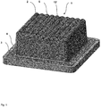
- Fig. 1 is the completed support body 1 with the assemblies cover 2, cover edge 3 and bottom plate 4 shown.
- the lid 2 has a cuboid contour with rounded edges and a lid top O, which is provided with wave-like arranged, mutually parallel grooves 5.
- the grooves 5 ensure a toothing effect between the lid 2 and cargo and thus leads to a better adhesion of the cargo, which comes to rest on the top cover O. The risk of slippage of the cargo during transport is thus reduced.
- the material of the cover 2 consists of Elastollan®, a thermoplastic polyurethane elastomer (TPU).
- TPU is characterized by good resilience, lightfastness and low-temperature flexibility. Preferred hardness ranges from 55 Shore A to 74 Shore A.
- the lid 2 runs in a flat, circumferential lid edge 3 of uniform width b.
- the lid edge 3 is peripherally surrounded by a peripheral frame 6 of the bottom plate 4 and is thermally welded to this.
- Fig.2 the inner structure and the components of the support body 1 are illustrated in an exploded view.
- the cover 2 with peripheral lid edge 3 at its bottom end are made in a one-piece injection molded part.
- the hollow, cuboid interior of the lid 2 takes the in Fig. 1 invisible core 7 up.
- Fig. 4 shown, from a rectangular grid structure 8 and a plurality of rod-shaped feet 9 together.
- the outer dimensions - width and length - of the lattice structure 8 substantially correspond to the rectangular cross-section of the interior of the lid 2.
- the feet 7 protrude perpendicularly from the plane of the lattice structure 8 and base respectively on the intersections 10 of the lattice structure 8.
- the free end of Feet 9 protrudes in the direction of the bottom plate 4, so that, as in Fig.
- the grid structure 8 comes to rest on the inside of the lid, while the free end of the feet 9 sit on the bottom plate 4 cover side.
- the bottom plate 4 on the cover side integrally formed, arranged like a checkered, annular elevations 11.
- the circular recesses 12 of the elevations 11 each protrude the free end of the feet 9 and is supported therein.
- the deformability of the feet 9 thus determined significantly the deformation behavior of the core 7 and thus of the core 7 enclosing cover 2 under pressure, which results from the overlying load.
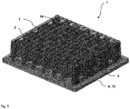
- the frame 6 has an L-shaped profile cross-section and comprises the peripheral lid edge 3 and the edge 13 of the bottom plate 4. Thermal bonding of lid edge 3 with frame 6 and edge 13 results in an insoluble, robust connection of the lid 2 with frame 6 and bottom plate 4.
- the core 7 is formed here by a block-shaped block, which also largely fills the interior of the lid 2 from the inside of the lid to the bottom plate 4.
- the core 7 is penetrated by rows of cylindrical bores 14, wherein the bores are aligned with their axis vertical to the bottom plate 4.
- the rows of holes 14 are arranged with offset from each other, so that the variation of the wall thicknesses in the core 7 between the holes 14 is minimized.
- the deformation behavior of the core 7 can be adapted via a variation of the bore diameter and number of the bores 14.
- Another variation of the deformation parameter is determined by the choice of core material. In the present case it is a plastic whose Shore hardness is different from the lid material.
- the bottom plate 4 has, corresponding to the holes 14 arranged, flat cylindrical elevations 11, which in each case protrude for fixing the core 7 on the bottom plate 4 in the holes 14.
Landscapes
- Engineering & Computer Science (AREA)
- Mechanical Engineering (AREA)
- Closures For Containers (AREA)
- Buffer Packaging (AREA)
Abstract
Description
- Die Erfindung betrifft einen formelastischen Auflagekörper zur Aufnahme von Ladegut in einem Behälter, nach dem Oberbegriff des Anspruches 1.
- Beim Transport und bei der Lagerung von Maschinenbauteilen und anderen festen Gütern in Behältnissen, wie z. B. auf Paletten, ist es häufig erforderlich, diese Bauteile auf dem Boden oder an Haltevorrichtungen der Behältnisse sicher festzulegen, um das wertvolle Transportgut vor Beschädigung zu schützen. Insbesondere ist darauf zu achten, dass beim Kontakt mit den Haltevorrichtungen beim Be- und Entladen aber auch bei Erschütterungen des Behältnisses, wie sie beim Transport auftreten können, keine Beschädigungen eintreten. Dabei sind selbst kleine Kratzer oder andere Beeinträchtigungen der Oberfläche des Transportgutes zu vermeiden.
- Für empfindliche und hochwertige Maschinenbauteile werden daher häufig speziell auf das einzelne Bauteil zugeschnittene Behälter mit definierten Festlegungsmitteln zur Sicherung gefertigt, wie sie beispielsweise aus der
US 4,735,310 bekannt sind. Meist handelt es sich hierbei um aufwendige Konstruktionen mit Metallbeschlägen. - Einen anderen Weg beschreitet eine aus der
DE 41 35 228 C bekannte Lösung. Dort wird ein kegelförmiger Auflagekörper vorgeschlagen, der das Ladegut an dessen kegelförmigen Umfang aufnimmt und festlegt. Die elastische Ausführung des Auflagekörpers erlaubt eine schonende Fixierung stoßempfindlicher Ladegüter. Als besonders vorteilhaft erweist sich hierbei die Verwendung eines Elastomers als Werkstoff für den Auflagekörper, wodurch nicht nur Stöße gedämpft werden sondern die Auflagefläche des Ladegutes vor Kratzern u.ä. Oberflächenbeschädigungen geschützt wird. - Eine weitere Aufnahme- und Fixiereinrichtung Aufnahme und von Transportgut ist in der
DE 10 2011 016 752 A1 veröffentlicht. Hierbei weist die Aufnahme- und Fixiereinrichtung einen Abschnitt zum Aufnehmen des Gegenstandes auf, der teilweise aus einem nachgiebigen, konturumfassenden, formadaptiven und schlagdämpfenden Material besteht. Um das Einsinken des Transportgutes in die Aufnahme- und Fixiereinrichtung zu begrenzen, sind Bereiche unterschiedlicher Härte oder Dichte vorgesehen. - Eine schonende Fixierung des Ladegutes durch einen weitgehend elastischen Auflagekörper stellt häufig einen Zielkonflikt mit den Anforderungen an die rohen Einsatzbedingungen und an eine robuste Anbindung des Auflagekörpers an den Behälter dar.
- Hiervon ausgehend ist es die Aufgabe der Erfindung einen gattungsgemäßen Auflagekörper anzugeben, der einerseits eine ladegutschonende und konturnahe Aufnahme gestattet und andererseits eine robuste Festlegung des Auflagekörpers in einem Behälter ermöglicht wird.
- Die Aufgabe wird durch einen erfindungsgemäßen Auflagekörper nach den Merkmalen des Anspruches 1 gelöst. Vorteilhafte Ausgestaltungen sind den abhängigen Ansprüchen zu entnehmen.
- Die wesentlichen Vorteile der Erfindung bestehen darin, dass mit den erfindungsgemäßen Separierung und Zuordnung der Aufgaben in baulich verschiedene Bauteile des Auflagekörpers, nämlich in Deckel und Bodenplatte eine zielkonfliktfreie Gestaltung des Auflagekörpers ermöglicht wird. Der Deckel besteht dabei aus einem Elastomer oder gummielastischen Polymer. Dies ermöglicht eine Anpassung von Deckel und Bodenplatte an steinschlag-, wasser- und kältegefährdeten Einsatzbedingungen, wie dies in den weiteren Merkmalen der Erfindung zum Ausdruck kommt.
- Der den Innenraum des Deckels zumindest teilweise ausfüllende Kern besteht ebenfalls aus einem Kunststoff, dessen Shore-Härte jedoch verschieden ist von der des Deckelmaterials. Der Kern verstärkt die Druckfestigkeit des Deckels und sorgt für einen rückstellenden Effekt wenn der Deckel unter Last deformiert und danach wieder entlastet wird. Dieser Effekt unterstützt das konturnahe Anschmiegen des Deckels an die Kontur des Ladegutes und führt hiermit zu einer äußerst materialschonenden Kontaktierung und Lagerung des Ladegutes. Durch entsprechendes Abstimmen der Shore-Härten von Deckel und Kern lässt sich der Effekt entsprechend des Einsatzumfeldes optimieren.
- Schließlich ist der Deckel mit der Bodenplatte thermisch verschweißt oder form- oder stoffschlüssig umspritzt und stellt damit eine robuste Verbindung zwischen Deckel und Bodenplatte dar.
- Bevorzugte Ausführungen ergeben sich aus den Unteransprüchen.
- Zur Erzielung guter Leistung mit einer großen Breite von mechanischen, thermischen, chemischen und elektrischen Eigenschaften empfiehlt sich die Verwendung eines Polymers aus der Gruppe Silikon, elastisches Polyurethan, TPU, Silikongel, Polyurethangel, Latex, Gummi, PVC oder Synthesekautschuk. Für gute Werte bei Reißfestigkeit und Biegewechselfestigkeit sowie für ein großes Betriebstemperaturspektrum wird die Verwendung eines thermoplastischen Polyurethan-Elastomers für den Werkstoff des Deckels und ggfs. auch des Kerns vorgeschlagen.
- Bei der Wahl des Werkstoffes der Bodenplatte ist zu beachten, dass diese eine höhere Shorhärte als die des Deckels aufweist. Dadurch lässt sich eine robustere Verbindung zwischen Bodenplatte und einem Behälter, z.B. einer Palette darstellen. Auch hier ist die Verwendung eines Elastomers oder Polymers vorteilhaft. Die Bodenplatte lässt sich wiederum mit üblichen Befestigungsmitteln, wie z.B. Schraub- oder Klemmverbindungen an einen Behälter anbringen.
- Was die geometrischen Abmessungen des Auflagekörpers anbelangt, so bietet sich eine Auswahl an verschiedenen Bauhöhen und Längen und Breiten im Rahmen einer überschaubaren Baureihenvariation an, um den unterschiedlichsten Abmessungen des zu erwartenden Ladegutes gerecht zu werden.
- Während dem Deckel in seiner Funktion primär die konturnahe und anschmiegende Kontaktierung und Fixierung des Ladegutes zukommt, lässt sich über die Gestaltung des Kerns in seiner Struktur und Werkstoffwahl primär das Verformungsverhalten des Auflagekörpers beeinflussen. Hierzu weist der Kern eine Anzahl von Stegen, die sich zur Übertragung von Druckkräften vom Deckel zur Bodenplatte erstrecken. In weiterer Ausbildung des Kerns sind stabförmige Stegstrukturen wie auch wabenförmige, mit Bohrungen durchzogene Kerne vorteilhaft.
- Die Erfindung kann noch besser verstanden werden, wenn Bezug auf die nachfolgenden Figuren genommen wird.
- Es zeigen:
- Fig. 1
- eine isometrische Ansicht des Auflagekörpers,
- Fig. 2
- eine Explosionsansicht des Auflagekörpers mit den Baugruppen Deckel, Kern, Rahmen und Bodenplatte,
- Fig. 3
- eine isometrische und transparente Ansicht des Auflagekörpers mit Multi-Stab-Kern,
- Fig. 4
- eine isometrische Ansicht des Kerns mit stabförmigen Füßen,
- Fig. 5
- eine isometrische und transparente Ansicht des Auflagekörpers mit Steg-Loch-Kern und
- Fig. 6
- eine Explosionsansicht des Auflagekörpers mit den Baugruppen Deckel, Kern (Steg-Loch-Kern), und Bodenplatte.
- In
Fig. 1 ist der komplettierte Auflagekörper 1 mit den Baugruppen Deckel 2, Deckelrand 3 und Bodenplatte 4 gezeigt. Der Deckel 2 weist eine quaderförmige Kontur mit abgerundeten Kanten und einer Deckeloberseite O auf, die mit wellenartig angeordneten, parallel zueinander verlaufenden Rillen 5 versehen ist. Die Rillen 5 sorgen für einen Verzahnungseffekt zwischen Deckel 2 und Ladegut und führt somit zu einer besseren Haftung des Ladegutes, welches auf der Deckeloberseite O zu liegen kommt. Die Gefahr eines Verrutschens des Ladegutes während des Transportes wird somit reduziert. - Der Werkstoff des Deckels 2 besteht aus Elastollan®, einem thermoplastischen Polyurethan-Elastomer (TPU). TPU zeichnet sich durch ein gutes Rückstellvermögen, Lichtechtheit und Kälteflexibilität aus. Bevorzugte Härten liegen zwischen 55 Shore A bis 74 Shore A.
- Bodenseitig läuft der Deckel 2 in einem flachen, umlaufenden Deckelrand 3 gleichmäßiger Breite b aus. Der Deckelrand 3 wird umfangsseitig von einem umlaufenden Rahmen 6 der Bodenplatte 4 umfasst und ist mit diesem thermisch verschweißt.
- In
Fig.2 sind der innere Aufbau und die Komponenten des Auflagekörpers 1 in einer Explosionszeichnung verdeutlicht. Der Deckel 2 mit umlaufenden Deckelrand 3 an seinem bodenseitigen Ende sind in einem einstückigen Spritzgussteil hergestellt. - Der hohle, quaderförmige Innenraum des Deckels 2 nimmt den in
Fig. 1 nicht sichtbaren Kern 7 auf. Dieser setzt sich, wie weiter inFig. 4 gezeigt, aus einer rechteckigen Gitterstruktur 8 und einer Vielzahl stabförmiger Füße 9 zusammen. Die äußeren Abmessungen - Breite und Länge - der Gitterstruktur 8 entsprechen im Wesentlichen dem rechteckigen Querschnitt des Innenraumes des Deckels 2. Die Füße 7 ragen senkrecht von der Ebene der Gitterstruktur 8 auf und fußen jeweils auf den Kreuzungen 10 der Gitterstruktur 8. Das freie Ende der Füße 9 ragt in Richtung der Bodenplatte 4, sodass, wie inFig. 3 dargestellt, im komplettierten Zustand des Auflagekörpers 1 die Gitterstruktur 8 auf der Deckelinnenseite zum Liegen kommt, während die freien Ende der Füße 9 auf der Bodenplatte 4 deckelseitig aufsitzen. Hierzu weist die Bodenplatte 4 deckelseitig angeformte, schachbrettartig angeordnete, ringförmige Erhebungen 11 auf. In den kreisrunden Vertiefungen 12 der Erhebungen 11 ragt jeweils das freie Ende der Füße 9 und stützt sich darin ab. - Die Verformbarkeit der Füße 9 bestimmt somit maßgeblich das Verformungsverhalten des Kernes 7 und somit des den Kern 7 umschließenden Deckels 2 bei Druckbelastung, welche sich durch das aufliegende Ladegut ergibt.
- Der Rahmen 6 weist einen L-förmigen Profil-Querschnitt auf und umfasst den umlaufenden Deckelrand 3 und den Rand 13 den Bodenplatte 4. Durch thermische Verschweißung von Deckelrand 3 mit Rahmen 6 und Rand 13 ergibt sich eine unlösbare, robuste Verbindung des Deckels 2 mit Rahmen 6 und Bodenplatte 4.
- Eine weitere Ausführungsform des Kerns 7 ist in den
Fig. 5 und6 gezeigt. Der Kern 7 wird hier von einem quaderförmigen Block gebildet, der ebenfalls den Innenraum des Deckels 2 von dessen Deckelinnenseite bis zur Bodenplatte 4 weitgehend ausfüllt. Der Kern 7 ist von Reihen zylindrischer Bohrungen 14 durchsetzt, wobei die Bohrungen mit ihrer Achse vertikal zur Bodenplatte 4 ausgerichtet sind. Die Reihen der Bohrungen 14 sind mit Versatz zueinander angeordnet, sodass die Variation der Wandstärken im Kern 7 zwischen den Bohrungen 14 minimiert wird. - Auch hier lässt sich über eine Variation der Bohrungsdurchmesser und Anzahl der Bohrungen 14 das Verformungsverhalten des Kerns 7 adaptieren. Eine weitere Variation des Verformungsparameters bestimmt sich durch die Wahl des Kernmaterials. Vorliegend handelt es sich um einen Kunststoff, dessen Shore-Härte vom Deckelmaterial verschieden ist.
- Die Bodenplatte 4 weist entsprechend den Bohrungen 14 angeordnete, flache zylindrische Erhebungen 11 auf, die jeweils zur Fixierung des Kerns 7 auf der Bodenplatte 4 in die Bohrungen 14 hineinragen.
-
- 1
- Auflagekörper
- 2
- Deckel
- 3
- Deckelrand
- 4
- Bodenplatte
- 5
- Rillen
- 6
- Rahmen
- 7
- Kern
- 8
- Gitterstruktur
- 9
- Fuß
- 10
- Kreuzung
- 11
- Erhebung
- 12
- Vertiefung
- 13
- Rand
- 14
- Bohrung
Claims (14)
- Formelastischer Auflagekörper (1) zur Aufnahme von Ladegut in einem Behälter, bestehend aus einem ladegutseitigen, becherförmigen Deckel (2), einem Kern (7), welcher das Innere des Deckels (2) zumindest teilweise ausfüllt, und einer Bodenplatte (4), welche den Deckel (2) mit Kern (7) verschließt, wobei• der Deckel (2) aus einem Elastomer oder gummielastischen Polymer besteht,• der Kern (7) aus einem Kunststoff besteht, dessen Shore-Härte verschieden ist von der des Deckelmaterials und die Druckfestigkeit des Deckels (2) verstärkt und• der Deckel (2) mit der Bodenplatte (4) thermisch verschweißt oder form- oder stoffschlüssig umspritzt ist.
- Auflagekörper nach Anspruch 1, dadurch gekennzeichnet, dass das Polymer ein Silikon, elastisches Polyurethan, TPU, Silikongel, Polyurethangel, Latex, Gummi, PVC oder Synthesekautschuk ist.
- Auflagekörper nach Anspruch 1, dadurch gekennzeichnet, dass das Elastomer ein thermoplastisches Polyurethan-Elastomer ist.
- Auflagekörper nach einem der vorhergehenden Ansprüche, dadurch gekennzeichnet, dass die Shore-Härte des Deckels (2) zwischen 55 Shore A und 74 Shore A liegt.
- Auflagekörper nach einem der vorhergehenden Ansprüche, dadurch gekennzeichnet, dass die Bodenplatte (4) aus einem Elastomer oder Polymer besteht.
- Auflagekörper nach einem der vorhergehenden Ansprüche, dadurch gekennzeichnet, dass die Shore-Härte des Deckels (2) geringer ist als die der Bodenplatte (4).
- Auflagekörper nach einem der vorhergehenden Ansprüche, dadurch gekennzeichnet, dass der Deckel (2) zur Aufnahme des Ladeguts zumindest teilflächig Vertiefungen (12') und/oder Erhebungen (11') aufweist.
- Auflagekörper nach einem der vorhergehenden Ansprüche, dadurch gekennzeichnet, dass der Deckel (2) einen quader- oder würfelförmigen Umriss aufweist.
- Auflagekörper nach einem der vorhergehenden Ansprüche, dadurch gekennzeichnet, dass der Deckel (2) mit einem Hohlraum zur Aufnahme des Kerns (7) versehen ist.
- Auflagekörper nach einem der vorhergehenden Ansprüche, dadurch gekennzeichnet, dass der Deckel (2) einen umlaufenden Deckelrand (3) aufweist, der auf der Bodenplatte (4) flächig aufliegt.
- Auflagekörper nach einem der vorhergehenden Ansprüche, dadurch gekennzeichnet, dass die Bodenplatte (4) Vertiefungen (12) und / oder Erhebungen (11) aufweist, die mit entsprechenden Erhebungen bzw. Vertiefungen seitens des Kerns (7) ineinandergreifen.
- Auflagekörper nach einem der vorhergehenden Ansprüche, dadurch gekennzeichnet, dass der Kern (7) eine Anzahl von stabförmigen Füßen (9) aufweist, die sich zur Übertragung von Druckkräften vom Deckel (2) zur Bodenplatte (4) erstrecken.
- Auflagekörper nach einem der vorhergehenden Ansprüche, dadurch gekennzeichnet, dass der Kern (7) mit dem Deckel (2) stoffschlüssig verbunden ist.
- Auflagekörper nach einem der vorhergehenden Ansprüche, dadurch gekennzeichnet, dass die Bodenplatte (4) und / oder der Kern (7) aus einem Elastomer oder gummielastischen Polymer besteht.
Applications Claiming Priority (1)
| Application Number | Priority Date | Filing Date | Title |
|---|---|---|---|
| DE102016012636.1A DE102016012636A1 (de) | 2016-10-22 | 2016-10-22 | Formelastischer Auflagekörper |
Publications (3)
| Publication Number | Publication Date |
|---|---|
| EP3321209A2 true EP3321209A2 (de) | 2018-05-16 |
| EP3321209A3 EP3321209A3 (de) | 2019-01-02 |
| EP3321209B1 EP3321209B1 (de) | 2020-02-26 |
Family
ID=60138153
Family Applications (1)
| Application Number | Title | Priority Date | Filing Date |
|---|---|---|---|
| EP17020452.3A Active EP3321209B1 (de) | 2016-10-22 | 2017-10-03 | Formelastischer auflagekörper |
Country Status (2)
| Country | Link |
|---|---|
| EP (1) | EP3321209B1 (de) |
| DE (1) | DE102016012636A1 (de) |
Cited By (1)
| Publication number | Priority date | Publication date | Assignee | Title |
|---|---|---|---|---|
| CN111845896A (zh) * | 2020-08-03 | 2020-10-30 | 李艳艳 | 一种数控机床的物料转移机构 |
Families Citing this family (1)
| Publication number | Priority date | Publication date | Assignee | Title |
|---|---|---|---|---|
| DE102018124440A1 (de) * | 2018-10-03 | 2020-04-09 | Willibald Hergeth | Formelastischer Auflagekörper |
Family Cites Families (17)
| Publication number | Priority date | Publication date | Assignee | Title |
|---|---|---|---|---|
| CH345588A (de) * | 1956-09-26 | 1960-03-31 | Marx & Cie | Transportbehälter für mindestens einen vorbestimmt geformten Gegenstand |
| GB1133198A (en) * | 1966-10-26 | 1968-11-13 | James Sutton Hardigg | Shock isolator element particularly for incorporation in a cushioned container unit and method of making the same |
| JPS518422B2 (de) | 1971-12-18 | 1976-03-16 | ||
| US4735310A (en) | 1987-01-15 | 1988-04-05 | Teledyne Industries, Inc. | Aircraft engine shipping container with adjustable bracket supports |
| DE8816945U1 (de) * | 1988-08-20 | 1991-04-18 | Teldix Gmbh, 69123 Heidelberg | Wiederverwendbare, in einem Behälter anzuordnende, Polsterung für die Lagerung und den Transport von empfindlichen Geräten |
| DE3834103C1 (de) | 1988-10-07 | 1990-01-18 | Fa. Carl Freudenberg, 6940 Weinheim, De | |
| DE4135228C2 (de) | 1991-10-25 | 1996-03-28 | Mtu Muenchen Gmbh | Vorrichtung zur Festlegung von Ladegut |
| DE19520645A1 (de) * | 1995-06-09 | 1996-12-12 | Reichenecker Hans Storopack | Vorrichtung zum Verpacken von Kraftfahrzeug-Scheiben |
| US5816395A (en) | 1995-09-25 | 1998-10-06 | Tkl Products Corp. | Foam-layered packaging case |
| US5749111A (en) | 1996-02-14 | 1998-05-12 | Teksource, Lc | Gelatinous cushions with buckling columns |
| DE19621782A1 (de) | 1996-05-30 | 1997-12-04 | Odenwald Chemie Gmbh | Abstandhalter aus Schaumstoff sowie Verwendung desselben und Verfahren zur Behandlung von Kraftfahrzeugblechen unter Verwendung solcher Abstandhalter |
| US7704024B2 (en) | 2006-01-31 | 2010-04-27 | General Electric Company | Methods and systems for transporting wind turbine components |
| JP5392452B2 (ja) * | 2008-02-25 | 2014-01-22 | 日産自動車株式会社 | 表面保護シート体 |
| DE102011016752A1 (de) * | 2010-12-23 | 2012-06-28 | Viebahn Systemtechnik Gmbh | Aufnahme- und Fixiereinrichtung |
| KR20130127671A (ko) | 2012-05-15 | 2013-11-25 | 실드에어코리아 주식회사 | 접이식 포장용 완충재 |
| EP2810986B1 (de) | 2013-06-05 | 2017-04-19 | Carl Freudenberg KG | Thermoplastische Elastomerzusammensetzung und deren Verwendung |
| DE102013016899A1 (de) | 2013-10-11 | 2015-05-21 | Josef Jansen | Gelenkspacer |
-
2016
- 2016-10-22 DE DE102016012636.1A patent/DE102016012636A1/de active Pending
-
2017
- 2017-10-03 EP EP17020452.3A patent/EP3321209B1/de active Active
Cited By (1)
| Publication number | Priority date | Publication date | Assignee | Title |
|---|---|---|---|---|
| CN111845896A (zh) * | 2020-08-03 | 2020-10-30 | 李艳艳 | 一种数控机床的物料转移机构 |
Also Published As
| Publication number | Publication date |
|---|---|
| EP3321209A3 (de) | 2019-01-02 |
| EP3321209B1 (de) | 2020-02-26 |
| DE102016012636A1 (de) | 2018-04-26 |
Similar Documents
| Publication | Publication Date | Title |
|---|---|---|
| EP3285970B1 (de) | Werkzeugakku-schutzschale | |
| EP0146846B1 (de) | Laufsohle für Schuhe, insbesondere Sportschuhe mit einstellbarer Fersendämpfung | |
| EP2906851B1 (de) | Hydraulisch dämpfendes buchsenlager | |
| EP2906852B1 (de) | Hydraulisch dämpfendes buchsenlager | |
| EP0995553A2 (de) | Schwingungsgedämpfter Handgriff | |
| EP1286732B1 (de) | Versteifungs- und/oder dämpfungselement für eine gleitvorrichtung, insbesondere für einen schi oder snowboard | |
| EP3321209B1 (de) | Formelastischer auflagekörper | |
| DE102020125855B4 (de) | Saugnapfanordnung und Verfahren zum Anheben eines Gegenstands | |
| DE1634060A1 (de) | Stossdaempfer bzw.Kaimauernpuffer | |
| EP1887248B1 (de) | Schichtfeder mit lastabhängiger progressiver Steifigkeit | |
| WO2005019048A1 (de) | Nestbarer ladungsträger | |
| EP2799356B1 (de) | Kunststoffbehälter | |
| EP1036014A1 (de) | Abstandhalter | |
| DE10148124A1 (de) | Gutförderer | |
| DE102019116419B4 (de) | Ablageeinrichtung | |
| EP3024051B1 (de) | Gehäuse für eine Akkumulatorzelle | |
| DE102018124440A1 (de) | Formelastischer Auflagekörper | |
| DE60317138T2 (de) | Schüttgut-Zwischenbehälter mit geringer Höhe | |
| DE2303124B2 (de) | Transportpalette | |
| DE102007059385A1 (de) | Applikator für Wirkstoff-Implantate | |
| EP3789087B1 (de) | Verwendung eines rettungseinsatz-lastvertelungselementes zur abstützung von druckerzeugenden rettungsgeräten | |
| DE102020105364A1 (de) | Verpackungsschale | |
| DE1212877B (de) | Ladeplatte, insbesondere fuer Flugzeuge | |
| DE102009049188A1 (de) | Vorrichtung zur Halterung von zu temperierenden Gegenständen | |
| EP3414468B1 (de) | Federungseinrichtung und befestigungseinrichtung zur befestigung eines maschinenelements sowie verwendung |
Legal Events
| Date | Code | Title | Description |
|---|---|---|---|
| PUAI | Public reference made under article 153(3) epc to a published international application that has entered the european phase |
Free format text: ORIGINAL CODE: 0009012 |
|
| STAA | Information on the status of an ep patent application or granted ep patent |
Free format text: STATUS: THE APPLICATION HAS BEEN PUBLISHED |
|
| AK | Designated contracting states |
Kind code of ref document: A2 Designated state(s): AL AT BE BG CH CY CZ DE DK EE ES FI FR GB GR HR HU IE IS IT LI LT LU LV MC MK MT NL NO PL PT RO RS SE SI SK SM TR |
|
| AX | Request for extension of the european patent |
Extension state: BA ME |
|
| PUAL | Search report despatched |
Free format text: ORIGINAL CODE: 0009013 |
|
| AK | Designated contracting states |
Kind code of ref document: A3 Designated state(s): AL AT BE BG CH CY CZ DE DK EE ES FI FR GB GR HR HU IE IS IT LI LT LU LV MC MK MT NL NO PL PT RO RS SE SI SK SM TR |
|
| AX | Request for extension of the european patent |
Extension state: BA ME |
|
| RIC1 | Information provided on ipc code assigned before grant |
Ipc: B65D 85/68 20060101ALN20181123BHEP Ipc: B65D 81/107 20060101AFI20181123BHEP Ipc: B65D 81/02 20060101ALI20181123BHEP |
|
| STAA | Information on the status of an ep patent application or granted ep patent |
Free format text: STATUS: REQUEST FOR EXAMINATION WAS MADE |
|
| 17P | Request for examination filed |
Effective date: 20190211 |
|
| RBV | Designated contracting states (corrected) |
Designated state(s): AL AT BE BG CH CY CZ DE DK EE ES FI FR GB GR HR HU IE IS IT LI LT LU LV MC MK MT NL NO PL PT RO RS SE SI SK SM TR |
|
| REG | Reference to a national code |
Ref country code: DE Ref legal event code: R079 Ref document number: 502017003923 Country of ref document: DE Free format text: PREVIOUS MAIN CLASS: B65D0081020000 Ipc: B65D0081107000 |
|
| RIC1 | Information provided on ipc code assigned before grant |
Ipc: B65D 81/107 20060101AFI20190430BHEP Ipc: B65D 85/68 20060101ALN20190430BHEP Ipc: B65D 81/02 20060101ALI20190430BHEP |
|
| GRAP | Despatch of communication of intention to grant a patent |
Free format text: ORIGINAL CODE: EPIDOSNIGR1 |
|
| STAA | Information on the status of an ep patent application or granted ep patent |
Free format text: STATUS: GRANT OF PATENT IS INTENDED |
|
| INTG | Intention to grant announced |
Effective date: 20190628 |
|
| GRAS | Grant fee paid |
Free format text: ORIGINAL CODE: EPIDOSNIGR3 |
|
| GRAA | (expected) grant |
Free format text: ORIGINAL CODE: 0009210 |
|
| STAA | Information on the status of an ep patent application or granted ep patent |
Free format text: STATUS: THE PATENT HAS BEEN GRANTED |
|
| AK | Designated contracting states |
Kind code of ref document: B1 Designated state(s): AL AT BE BG CH CY CZ DE DK EE ES FI FR GB GR HR HU IE IS IT LI LT LU LV MC MK MT NL NO PL PT RO RS SE SI SK SM TR |
|
| REG | Reference to a national code |
Ref country code: GB Ref legal event code: FG4D Free format text: NOT ENGLISH |
|
| REG | Reference to a national code |
Ref country code: CH Ref legal event code: EP |
|
| REG | Reference to a national code |
Ref country code: AT Ref legal event code: REF Ref document number: 1237371 Country of ref document: AT Kind code of ref document: T Effective date: 20200315 |
|
| REG | Reference to a national code |
Ref country code: IE Ref legal event code: FG4D Free format text: LANGUAGE OF EP DOCUMENT: GERMAN |
|
| REG | Reference to a national code |
Ref country code: DE Ref legal event code: R096 Ref document number: 502017003923 Country of ref document: DE |
|
| PG25 | Lapsed in a contracting state [announced via postgrant information from national office to epo] |
Ref country code: RS Free format text: LAPSE BECAUSE OF FAILURE TO SUBMIT A TRANSLATION OF THE DESCRIPTION OR TO PAY THE FEE WITHIN THE PRESCRIBED TIME-LIMIT Effective date: 20200226 Ref country code: NO Free format text: LAPSE BECAUSE OF FAILURE TO SUBMIT A TRANSLATION OF THE DESCRIPTION OR TO PAY THE FEE WITHIN THE PRESCRIBED TIME-LIMIT Effective date: 20200526 Ref country code: FI Free format text: LAPSE BECAUSE OF FAILURE TO SUBMIT A TRANSLATION OF THE DESCRIPTION OR TO PAY THE FEE WITHIN THE PRESCRIBED TIME-LIMIT Effective date: 20200226 |
|
| REG | Reference to a national code |
Ref country code: NL Ref legal event code: MP Effective date: 20200226 |
|
| REG | Reference to a national code |
Ref country code: LT Ref legal event code: MG4D |
|
| PG25 | Lapsed in a contracting state [announced via postgrant information from national office to epo] |
Ref country code: HR Free format text: LAPSE BECAUSE OF FAILURE TO SUBMIT A TRANSLATION OF THE DESCRIPTION OR TO PAY THE FEE WITHIN THE PRESCRIBED TIME-LIMIT Effective date: 20200226 Ref country code: LV Free format text: LAPSE BECAUSE OF FAILURE TO SUBMIT A TRANSLATION OF THE DESCRIPTION OR TO PAY THE FEE WITHIN THE PRESCRIBED TIME-LIMIT Effective date: 20200226 Ref country code: SE Free format text: LAPSE BECAUSE OF FAILURE TO SUBMIT A TRANSLATION OF THE DESCRIPTION OR TO PAY THE FEE WITHIN THE PRESCRIBED TIME-LIMIT Effective date: 20200226 Ref country code: IS Free format text: LAPSE BECAUSE OF FAILURE TO SUBMIT A TRANSLATION OF THE DESCRIPTION OR TO PAY THE FEE WITHIN THE PRESCRIBED TIME-LIMIT Effective date: 20200626 Ref country code: GR Free format text: LAPSE BECAUSE OF FAILURE TO SUBMIT A TRANSLATION OF THE DESCRIPTION OR TO PAY THE FEE WITHIN THE PRESCRIBED TIME-LIMIT Effective date: 20200527 Ref country code: BG Free format text: LAPSE BECAUSE OF FAILURE TO SUBMIT A TRANSLATION OF THE DESCRIPTION OR TO PAY THE FEE WITHIN THE PRESCRIBED TIME-LIMIT Effective date: 20200526 |
|
| PG25 | Lapsed in a contracting state [announced via postgrant information from national office to epo] |
Ref country code: NL Free format text: LAPSE BECAUSE OF FAILURE TO SUBMIT A TRANSLATION OF THE DESCRIPTION OR TO PAY THE FEE WITHIN THE PRESCRIBED TIME-LIMIT Effective date: 20200226 |
|
| PG25 | Lapsed in a contracting state [announced via postgrant information from national office to epo] |
Ref country code: SK Free format text: LAPSE BECAUSE OF FAILURE TO SUBMIT A TRANSLATION OF THE DESCRIPTION OR TO PAY THE FEE WITHIN THE PRESCRIBED TIME-LIMIT Effective date: 20200226 Ref country code: LT Free format text: LAPSE BECAUSE OF FAILURE TO SUBMIT A TRANSLATION OF THE DESCRIPTION OR TO PAY THE FEE WITHIN THE PRESCRIBED TIME-LIMIT Effective date: 20200226 Ref country code: PT Free format text: LAPSE BECAUSE OF FAILURE TO SUBMIT A TRANSLATION OF THE DESCRIPTION OR TO PAY THE FEE WITHIN THE PRESCRIBED TIME-LIMIT Effective date: 20200719 Ref country code: ES Free format text: LAPSE BECAUSE OF FAILURE TO SUBMIT A TRANSLATION OF THE DESCRIPTION OR TO PAY THE FEE WITHIN THE PRESCRIBED TIME-LIMIT Effective date: 20200226 Ref country code: CZ Free format text: LAPSE BECAUSE OF FAILURE TO SUBMIT A TRANSLATION OF THE DESCRIPTION OR TO PAY THE FEE WITHIN THE PRESCRIBED TIME-LIMIT Effective date: 20200226 Ref country code: RO Free format text: LAPSE BECAUSE OF FAILURE TO SUBMIT A TRANSLATION OF THE DESCRIPTION OR TO PAY THE FEE WITHIN THE PRESCRIBED TIME-LIMIT Effective date: 20200226 Ref country code: DK Free format text: LAPSE BECAUSE OF FAILURE TO SUBMIT A TRANSLATION OF THE DESCRIPTION OR TO PAY THE FEE WITHIN THE PRESCRIBED TIME-LIMIT Effective date: 20200226 Ref country code: EE Free format text: LAPSE BECAUSE OF FAILURE TO SUBMIT A TRANSLATION OF THE DESCRIPTION OR TO PAY THE FEE WITHIN THE PRESCRIBED TIME-LIMIT Effective date: 20200226 Ref country code: SM Free format text: LAPSE BECAUSE OF FAILURE TO SUBMIT A TRANSLATION OF THE DESCRIPTION OR TO PAY THE FEE WITHIN THE PRESCRIBED TIME-LIMIT Effective date: 20200226 |
|
| REG | Reference to a national code |
Ref country code: DE Ref legal event code: R026 Ref document number: 502017003923 Country of ref document: DE |
|
| PLBI | Opposition filed |
Free format text: ORIGINAL CODE: 0009260 |
|
| PLAX | Notice of opposition and request to file observation + time limit sent |
Free format text: ORIGINAL CODE: EPIDOSNOBS2 |
|
| 26 | Opposition filed |
Opponent name: VIEBAHN SYSTEMTECHNIK GMBH Effective date: 20201126 |
|
| PG25 | Lapsed in a contracting state [announced via postgrant information from national office to epo] |
Ref country code: IT Free format text: LAPSE BECAUSE OF FAILURE TO SUBMIT A TRANSLATION OF THE DESCRIPTION OR TO PAY THE FEE WITHIN THE PRESCRIBED TIME-LIMIT Effective date: 20200226 |
|
| PG25 | Lapsed in a contracting state [announced via postgrant information from national office to epo] |
Ref country code: SI Free format text: LAPSE BECAUSE OF FAILURE TO SUBMIT A TRANSLATION OF THE DESCRIPTION OR TO PAY THE FEE WITHIN THE PRESCRIBED TIME-LIMIT Effective date: 20200226 Ref country code: PL Free format text: LAPSE BECAUSE OF FAILURE TO SUBMIT A TRANSLATION OF THE DESCRIPTION OR TO PAY THE FEE WITHIN THE PRESCRIBED TIME-LIMIT Effective date: 20200226 |
|
| PLAF | Information modified related to communication of a notice of opposition and request to file observations + time limit |
Free format text: ORIGINAL CODE: EPIDOSCOBS2 |
|
| REG | Reference to a national code |
Ref country code: CH Ref legal event code: PL |
|
| PLBB | Reply of patent proprietor to notice(s) of opposition received |
Free format text: ORIGINAL CODE: EPIDOSNOBS3 |
|
| PG25 | Lapsed in a contracting state [announced via postgrant information from national office to epo] |
Ref country code: LU Free format text: LAPSE BECAUSE OF NON-PAYMENT OF DUE FEES Effective date: 20201003 Ref country code: MC Free format text: LAPSE BECAUSE OF FAILURE TO SUBMIT A TRANSLATION OF THE DESCRIPTION OR TO PAY THE FEE WITHIN THE PRESCRIBED TIME-LIMIT Effective date: 20200226 |
|
| REG | Reference to a national code |
Ref country code: BE Ref legal event code: MM Effective date: 20201031 |
|
| PG25 | Lapsed in a contracting state [announced via postgrant information from national office to epo] |
Ref country code: LI Free format text: LAPSE BECAUSE OF NON-PAYMENT OF DUE FEES Effective date: 20201031 Ref country code: BE Free format text: LAPSE BECAUSE OF NON-PAYMENT OF DUE FEES Effective date: 20201031 Ref country code: CH Free format text: LAPSE BECAUSE OF NON-PAYMENT OF DUE FEES Effective date: 20201031 |
|
| PG25 | Lapsed in a contracting state [announced via postgrant information from national office to epo] |
Ref country code: IE Free format text: LAPSE BECAUSE OF NON-PAYMENT OF DUE FEES Effective date: 20201003 |
|
| PG25 | Lapsed in a contracting state [announced via postgrant information from national office to epo] |
Ref country code: TR Free format text: LAPSE BECAUSE OF FAILURE TO SUBMIT A TRANSLATION OF THE DESCRIPTION OR TO PAY THE FEE WITHIN THE PRESCRIBED TIME-LIMIT Effective date: 20200226 Ref country code: MT Free format text: LAPSE BECAUSE OF FAILURE TO SUBMIT A TRANSLATION OF THE DESCRIPTION OR TO PAY THE FEE WITHIN THE PRESCRIBED TIME-LIMIT Effective date: 20200226 Ref country code: CY Free format text: LAPSE BECAUSE OF FAILURE TO SUBMIT A TRANSLATION OF THE DESCRIPTION OR TO PAY THE FEE WITHIN THE PRESCRIBED TIME-LIMIT Effective date: 20200226 |
|
| GBPC | Gb: european patent ceased through non-payment of renewal fee |
Effective date: 20211003 |
|
| PG25 | Lapsed in a contracting state [announced via postgrant information from national office to epo] |
Ref country code: MK Free format text: LAPSE BECAUSE OF FAILURE TO SUBMIT A TRANSLATION OF THE DESCRIPTION OR TO PAY THE FEE WITHIN THE PRESCRIBED TIME-LIMIT Effective date: 20200226 Ref country code: AL Free format text: LAPSE BECAUSE OF FAILURE TO SUBMIT A TRANSLATION OF THE DESCRIPTION OR TO PAY THE FEE WITHIN THE PRESCRIBED TIME-LIMIT Effective date: 20200226 |
|
| PG25 | Lapsed in a contracting state [announced via postgrant information from national office to epo] |
Ref country code: GB Free format text: LAPSE BECAUSE OF NON-PAYMENT OF DUE FEES Effective date: 20211003 |
|
| REG | Reference to a national code |
Ref country code: DE Ref legal event code: R100 Ref document number: 502017003923 Country of ref document: DE |
|
| PLCK | Communication despatched that opposition was rejected |
Free format text: ORIGINAL CODE: EPIDOSNREJ1 |
|
| PLBN | Opposition rejected |
Free format text: ORIGINAL CODE: 0009273 |
|
| STAA | Information on the status of an ep patent application or granted ep patent |
Free format text: STATUS: OPPOSITION REJECTED |
|
| 27O | Opposition rejected |
Effective date: 20220915 |
|
| REG | Reference to a national code |
Ref country code: AT Ref legal event code: MM01 Ref document number: 1237371 Country of ref document: AT Kind code of ref document: T Effective date: 20221003 |
|
| PG25 | Lapsed in a contracting state [announced via postgrant information from national office to epo] |
Ref country code: AT Free format text: LAPSE BECAUSE OF NON-PAYMENT OF DUE FEES Effective date: 20221003 |
|
| PGFP | Annual fee paid to national office [announced via postgrant information from national office to epo] |
Ref country code: FR Payment date: 20240208 Year of fee payment: 8 |
|
| REG | Reference to a national code |
Ref country code: DE Ref legal event code: R081 Ref document number: 502017003923 Country of ref document: DE Owner name: TRANSPOFIX BETRIEBSGESELLSCHAFT MBH & CO. KG, DE Free format text: FORMER OWNER: HERGETH, WILLIBALD, 92334 BERCHING, DE |
|
| PGFP | Annual fee paid to national office [announced via postgrant information from national office to epo] |
Ref country code: DE Payment date: 20251031 Year of fee payment: 9 |