EP2906852B1 - Hydraulisch dämpfendes buchsenlager - Google Patents
Hydraulisch dämpfendes buchsenlager Download PDFInfo
- Publication number
- EP2906852B1 EP2906852B1 EP13733287.0A EP13733287A EP2906852B1 EP 2906852 B1 EP2906852 B1 EP 2906852B1 EP 13733287 A EP13733287 A EP 13733287A EP 2906852 B1 EP2906852 B1 EP 2906852B1
- Authority
- EP
- European Patent Office
- Prior art keywords
- axial
- damping
- chamber
- chambers
- radial
- Prior art date
- Legal status (The legal status is an assumption and is not a legal conclusion. Google has not performed a legal analysis and makes no representation as to the accuracy of the status listed.)
- Not-in-force
Links
Images


Classifications
-
- F—MECHANICAL ENGINEERING; LIGHTING; HEATING; WEAPONS; BLASTING
- F16—ENGINEERING ELEMENTS AND UNITS; GENERAL MEASURES FOR PRODUCING AND MAINTAINING EFFECTIVE FUNCTIONING OF MACHINES OR INSTALLATIONS; THERMAL INSULATION IN GENERAL
- F16F—SPRINGS; SHOCK-ABSORBERS; MEANS FOR DAMPING VIBRATION
- F16F13/00—Units comprising springs of the non-fluid type as well as vibration-dampers, shock-absorbers, or fluid springs
- F16F13/04—Units comprising springs of the non-fluid type as well as vibration-dampers, shock-absorbers, or fluid springs comprising both a plastics spring and a damper, e.g. a friction damper
- F16F13/06—Units comprising springs of the non-fluid type as well as vibration-dampers, shock-absorbers, or fluid springs comprising both a plastics spring and a damper, e.g. a friction damper the damper being a fluid damper, e.g. the plastics spring not forming a part of the wall of the fluid chamber of the damper
- F16F13/08—Units comprising springs of the non-fluid type as well as vibration-dampers, shock-absorbers, or fluid springs comprising both a plastics spring and a damper, e.g. a friction damper the damper being a fluid damper, e.g. the plastics spring not forming a part of the wall of the fluid chamber of the damper the plastics spring forming at least a part of the wall of the fluid chamber of the damper
- F16F13/14—Units of the bushing type, i.e. loaded predominantly radially
- F16F13/16—Units of the bushing type, i.e. loaded predominantly radially specially adapted for receiving axial loads
-
- F—MECHANICAL ENGINEERING; LIGHTING; HEATING; WEAPONS; BLASTING
- F16—ENGINEERING ELEMENTS AND UNITS; GENERAL MEASURES FOR PRODUCING AND MAINTAINING EFFECTIVE FUNCTIONING OF MACHINES OR INSTALLATIONS; THERMAL INSULATION IN GENERAL
- F16F—SPRINGS; SHOCK-ABSORBERS; MEANS FOR DAMPING VIBRATION
- F16F13/00—Units comprising springs of the non-fluid type as well as vibration-dampers, shock-absorbers, or fluid springs
- F16F13/04—Units comprising springs of the non-fluid type as well as vibration-dampers, shock-absorbers, or fluid springs comprising both a plastics spring and a damper, e.g. a friction damper
- F16F13/06—Units comprising springs of the non-fluid type as well as vibration-dampers, shock-absorbers, or fluid springs comprising both a plastics spring and a damper, e.g. a friction damper the damper being a fluid damper, e.g. the plastics spring not forming a part of the wall of the fluid chamber of the damper
- F16F13/08—Units comprising springs of the non-fluid type as well as vibration-dampers, shock-absorbers, or fluid springs comprising both a plastics spring and a damper, e.g. a friction damper the damper being a fluid damper, e.g. the plastics spring not forming a part of the wall of the fluid chamber of the damper the plastics spring forming at least a part of the wall of the fluid chamber of the damper
- F16F13/14—Units of the bushing type, i.e. loaded predominantly radially
- F16F13/1418—Units of the bushing type, i.e. loaded predominantly radially characterised by the location or shape of the equilibration chamber
-
- F—MECHANICAL ENGINEERING; LIGHTING; HEATING; WEAPONS; BLASTING
- F16—ENGINEERING ELEMENTS AND UNITS; GENERAL MEASURES FOR PRODUCING AND MAINTAINING EFFECTIVE FUNCTIONING OF MACHINES OR INSTALLATIONS; THERMAL INSULATION IN GENERAL
- F16F—SPRINGS; SHOCK-ABSORBERS; MEANS FOR DAMPING VIBRATION
- F16F13/00—Units comprising springs of the non-fluid type as well as vibration-dampers, shock-absorbers, or fluid springs
- F16F13/04—Units comprising springs of the non-fluid type as well as vibration-dampers, shock-absorbers, or fluid springs comprising both a plastics spring and a damper, e.g. a friction damper
- F16F13/06—Units comprising springs of the non-fluid type as well as vibration-dampers, shock-absorbers, or fluid springs comprising both a plastics spring and a damper, e.g. a friction damper the damper being a fluid damper, e.g. the plastics spring not forming a part of the wall of the fluid chamber of the damper
- F16F13/08—Units comprising springs of the non-fluid type as well as vibration-dampers, shock-absorbers, or fluid springs comprising both a plastics spring and a damper, e.g. a friction damper the damper being a fluid damper, e.g. the plastics spring not forming a part of the wall of the fluid chamber of the damper the plastics spring forming at least a part of the wall of the fluid chamber of the damper
- F16F13/18—Units comprising springs of the non-fluid type as well as vibration-dampers, shock-absorbers, or fluid springs comprising both a plastics spring and a damper, e.g. a friction damper the damper being a fluid damper, e.g. the plastics spring not forming a part of the wall of the fluid chamber of the damper the plastics spring forming at least a part of the wall of the fluid chamber of the damper characterised by the location or the shape of the equilibration chamber, e.g. the equilibration chamber, surrounding the plastics spring or being annular
Definitions
- the present invention relates to a hydraulically damping bushing bearing having an inner part, an outer bushing and an elastomeric damping member arranged between the outer bushing and the inner part.
- a hydraulic damping bush bearing is from the DE 103 59 340 A1 and from the EP 0 452 169 A1 known and also has an axial chamber pair with at least two offset in the axial direction of the inner part to each other and communicating with each other via at least one Axialcrokanal communicating axial chambers.
- a radial chamber pair is provided with at least two radial chambers, which are provided between the axial chambers and offset in the circumferential direction of the inner part, and which communicate via at least one radial damping channel.
- the damping part is elongated, usually designed as a cylinder. Regularly, the inner part in the generic bush bearing has a bore for receiving an axle pin of a machine element or component to be stored.
- the hydraulically damping bush bearing includes chambers for receiving a hydraulic damping fluid, which supports the damping.
- elastomeric inserts or rubber bodies of the hydraulically damping sleeve bearing chambers are accordingly provided for receiving the damping fluid to use the caused by this damping fluid Tilger bin.
- the exact size and position of the combs depends on the intended use of the hydraulically damping bearing, in particular the corresponding desired damping effects in the axial, ie longitudinal direction of the inner part and a direction transverse thereto, ie radial direction.
- the Vibration behavior of the component to be stored is also important, as well as the weight of the mass to be stored and attenuated.
- the chambers are usually connected by one or more channels.
- the hydraulic damping means can accordingly be pressed from one chamber to the other.
- both bearings in which the hydraulic damping is used in relation to radially registered in the bush bearing forces, as well as those in which primarily the damping is supported by the axial damping fluid.
- the aforementioned prior art is a reference to a bushing bearing in which the absorber effect is utilized in both the axial and radial directions.
- the present invention is based on the problem of specifying a hydraulically damping bush bearing which shows good damping even at higher frequencies.
- the present invention wants to specify a hydraulically damping bush bearing which causes no unwanted high damping at higher frequencies in the radial direction.
- the hydraulic damping bearing solid avoid in the prior art hardening crack at higher frequencies from about 250 Hz, especially in radial damping.
- the present invention proposes a hydraulic damping bush bearing having the features of claim 1.
- the hydraulically damping bush bearing has an elongated inner part in a conventional manner.
- This elongate inner part has, in a manner known per se, a bore running along the longitudinal axis, which also acts as a blind hole, i. can not be continuously formed.
- the bore runs regularly in the longitudinal direction of the elongated inner part, which is accordingly formed as a sleeve.
- this inner part is usually surmounted by a stop disc, which serves to mount the machine element or component to be damped.
- On this connection side there is also a usually continuously formed in the circumferential direction axial chamber, which communicates via at least one axial channel with an axial compensation chamber on another side of the bush bearing.
- the elastomeric damping member which is usually formed from an elastomeric material and may be stiffened by a cage which is completely vulcanized into the elastomeric material of the damping member.
- the elastomeric damping member usually forms at opposite peripheral portion of two radial chambers, which communicate with each other via at least one radial channel and form the radial chamber pair.
- two radial chambers are well known in the art.
- the present invention is not limited to such a configuration. Rather, the bush bearing according to the invention may also have three, four or more distributed on the circumference provided radial chambers, which form the radial chamber pair.
- the hydraulically damping bush bearing preferably includes additional elements that perform various functions.
- additional elements In two radial chambers only two additional elements can be provided.
- the additional elements extend on the one hand within bulges formed by the elastomeric damping member for the radial chambers and form corresponding edge surfaces for these radial chambers.
- the additional elements are based in the radial direction on the outside usually on an outer circumference of the socket bearing limiting bushing and serve as a radial stop, the excessive radial deflection of the bush bearing under displacement of the in the prevents both radial chambers provided damping fluid.
- the additional elements regularly form, between their outer peripheral surface and the inner peripheral surface of the bushing, said radial and axial channels.
- the channels can be long, short, wide or narrow.
- An axial channel connects the at least two axial chambers of the Axialhuntplos.
- the axial channels or the axial channels do not usually extend strictly in the axial direction, but also run in the circumferential direction.
- these additional elements form the at least one radial channel, which connects the radial chambers with each other. This radial channel is usually designed extending in the additional elements alone in the circumferential direction.
- the outer peripheral surface is provided with the radial and axial channels forming recesses.
- the axial extent of the additional elements is at the level of the radial chambers, ie where the additional elements engage in the formed by the elastomeric damping member bulges, less than between these radial chambers. Between the radial chambers, the additional elements in the axial direction usually extend from said axial compensation chamber to approximately to the other axial chamber.
- the axial chamber provided there is divided at least on one side of the radial chambers. There are on this one side a plurality of spaced apart and separate first axial chambers. Accordingly, the damping fluid can not circulate freely in the axial chamber at this one side, which is usually the connection side opposite. Rather, a plurality of annular segments formed as first axial chambers are provided in the circumferential direction, which limit the radial mobility of the damping fluid.
- the individual first axial chambers are usually in each case via a separate axial channel with the generally fully circumferential circumferential axial chamber on the other side in combination.
- connection side ie the side over which an axially supported and to be damped load of a component to be stored is introduced into the hydraulically damping bush bearing.
- axial chamber divided on the connection side in the circumferential direction.
- each ring segment can be assigned on the one hand, a ring-segment-shaped axial chamber on the connection side, wherein in each case one axial channel connects only associated ring-segment-shaped chambers on the connection and the other side.
- the circumferentially spaced apart first axial chambers are separated from one another by a partition formed from the elastomeric damping member.
- This division usually has the contour of the first axial chambers in the cross-sectional direction.
- the first axial chambers are formed by a counter-membrane, which is usually arranged on the end of the bush.
- the counter-membrane preferably forms an annular gap which runs around in the circumferential direction and which is formed in the circumferential direction with a constant cross-section.
- the division formed by the elastomeric damping member has a contour corresponding to this cross section and protrudes into the annular channel in such a way that the inner surface of the annular channel rests against the outer surface of the partition in an initial state and accordingly divides and separates the first axial chambers from one another.
- the counter membrane can lift off from the division, so that the separation is canceled.
- the initial state which depends on the preload of the hydraulically damping bushing bearing, however, the opposite membrane abuts the pitch.
- At least one liquid-empty damping chamber is provided between the axial chambers offset from one another in the axial direction and separates the radial and the axial chambers from one another.
- the axial chambers offset from one another in the axial direction are usually the damping chamber provided on the connection side on the one hand and the axial compensation chamber usually provided at the opposite end of the bush bearing on the other hand.
- the liquid-empty damping chamber is filled with a gas, in particular air. Usually, the liquid-empty damping chamber is sealed, so that upon compression of the damping chamber of the chamber contents is compressed and not expelled from the chamber.
- the liquid-empty damping chamber is accordingly able to absorb in particular higher frequencies of axial stresses by compression of the medium absorbed in the liquid-empty damping chamber, as a rule of a gas.
- the hydraulic bush bearing according to the invention is therefore relatively soft even with radial vibrations with higher frequencies from 250 Hz. An undesirable high attenuation does not occur.
- the liquid-empty damping chamber is preferably formed continuously in the circumferential direction, so that the fluid contained in this chamber can move freely in the circumferential direction during a compensating movement. In the first case, this applies to the radial excitation. Here comes the biggest effect.
- the liquid-empty damping chamber is partially formed by the elastomeric damping member and partially by walls of a patch on the elastomeric damping member intermediate membrane element.
- This intermediate membrane element usually separates the liquid-empty damping chamber from a regularly axially adjacent thereto provided axially on one side axial chamber.
- the intermediate membrane element preferably has the task of sealing in and enclosing the liquid-empty chamber.
- the intermediate membrane element usually has on its inner circumferential surface a support ring, which rests against the outer peripheral surface of the inner part.
- the intermediate membrane element is preferably reinforced by an annular disc.
- Both the annular disc and the support ring are formed from a hard material, such as a thermoplastic or metal, so that they deform at the very least slightly when pressing the intermediate membrane element into an annular gap between the sleeve and the inner part.
- the annular disc is usually formed as a core and covered with an elastomeric material, which is also vulcanized onto the outer peripheral surface of the support ring.
- the intermediate membrane element immediately adjacent to the outer peripheral surface of the support ring, preferably forms an annular chamber segment, which forms an annular chamber of the liquid-empty damping chamber. Furthermore, according to a preferred development of the following invention, the intermediate membrane element forms a sealing segment which can be applied sealingly against the elastomeric damping element.
- This seal segment is usually there on the elastomeric attenuator, where this is reinforced by the aforementioned cage.
- the elastomeric damping member in the contact region to the sealing surface formed by the sealing segment has a stiffening element, which reinforces the elastomeric damping member, in particular in the axial direction, said stiffening element is usually formed by the cage.
- the intermediate membrane element is preferably designed such that an inner annular wall portion of the annular chamber segment can be pushed onto the inner part and fixed in the axial direction relative to the inner part such that the sealing segment in a unstrained initial state with respect to an end face of the Ringwandungsabitess in the direction of the elastomeric damping member protrudes with offset.
- the inner part for axially fixing the inner annular wall section forms an annular contact surface which is at the same height as the contact area for the sealing segment formed by the elastomeric damping element, the sealing surface projects beyond the intermediate membrane element in an unstressed state the voltage applied to the annular surface end face of the inner Ringwandungsabiteses. If the intermediate membrane element is now installed, the sealing segment initially contacts the abutment region of the elastomeric damping element.
- the elastomeric material of the intermediate membrane element stores a resulting axial prestress within the intermediate membrane element urging the sealing segment against the elastomeric damping element.
- a stop element is proposed according to a preferred development, which is arranged in the liquid-empty damping chamber. Regularly at least two stop elements are realized, which lie opposite each other in the radial direction.
- the stop element is preferably with the intermediate membrane element connected and cooperates with the elastomeric attenuator. Consequently, a damped and soft striking can be achieved by the material properties of the elastomeric damping member, whereas the stopper member itself can be formed of a harder material, such as a conventional thermoplastic.
- the stop element is preferably made as a separate component and connected to a core of the intermediate membrane element.
- This core is, in particular, the previously mentioned annular disk of the intermediate membrane element, which may be formed of a harder material.
- the stop element and / or the core can be made of plastic, wherein at least one of the elements in two-part design has one or more integrally molded thereon pins for the connection of both parts.
- the figures show an embodiment of a hydraulically damping bushing bearing with a marked reference numeral 2 socket, which is arranged concentrically to an inner part 4, which passes through the socket 2.
- the socket 2 has an enlarged diameter on a connecting side marked with reference 6 and basically forms two cylinder sections which are connected to one another via a contact shoulder 8.
- the diameter-distributed connection side of the bushing 2 has an axial bearing membrane, designated by reference numeral 10, which is reinforced at its outer periphery by a retaining ring 12 and at its inner circumference by a support flange 14.
- the retaining ring 12 and the support flange 14 are connected to the elastomeric material forming the bearing membrane 10 by vulcanization.
- the one-piece bearing membrane element 16 thus formed is pressed into the annular gap between the bushing 2 and the inner part 4.
- the sleeve 2 is beaded on its abutment side and engages over the retaining ring 12.
- the bearing diaphragm 10 forms at opposite peripheral portions in each case a stop buffer 18, which is surmounted by an axial stop disc 20 which is associated with the inner part 4 and connected thereto , and which acts axially on the underside of the bush bearing.
- the axial stop disc 20 rests on a radially extending annular portion of the support flange 14.
- an axial counter-membrane 24 which - like the bearing membrane 10 described above - annularly shaped and radially inwardly by a support ring 26 and radially outwardly reinforced by a retaining ring 28.
- the inner part 4 forms a Gegenmembranstromschulter 32, against which the elastomeric material of the counter-membrane 24 under the pressing force of the pressed-on the inner part 4 support ring 26 sealingly.
- an elastomeric damping member 34 is provided, which consists of a elastomeric material is formed and in which a formed of a sheet material shaped cage 36 is vulcanized and radial chamber walls 35 is formed.
- This cage 36 extends substantially over the entire axial extent of the elastomeric damping member 34.
- the cage 36 amplifies a contact surface formed by the elastomeric damping member 34 for abutment of the counter-membrane element 30 at the level of the retaining ring 24 which is fixed by a beading of the bushing in the axial direction.
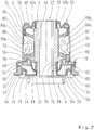
- the elastomeric damping member 34 further forms graduations indicated by reference numeral 38 at radially opposite sides whose contours correspond to the contour of an annular channel 40 formed by the counter-diaphragm ( see. FIG. 1 . FIG. 3 ).
- the annular channel 40 is divided in the circumferential direction into two substantially equal, first axial chambers 42, which are used as separate axial chambers 42 a, 42 b in FIG. 2 indicated. These axial chambers 42 a, b extend in the circumferential direction approximately at an angle of 160 degrees.
- the annular channel 40 communicates with a formed at the front end of the elastomeric damping member 34 trough 44, which is like the annular channel 40 divided by the division 38 in peripheral portions.
- the circumferentially separate trough portions belong to the two first axial chambers 42 a, 42 b.
- a corresponding recess 46 is formed on the opposite end face of the elastomeric damping member 34.
- This trough 46 is covered by an intermediate membrane element designated by reference numeral 48 which comprises an intermediate membrane 50 extending substantially in the radial direction, an intermediate membrane support ring 52, an annular disc 50 forming a core of the intermediate membrane member 48, and stop members 56 identified in the radial direction opposite (cf. FIG. 2 ).
- the intermediate membrane support ring 52 and the annular disc 54 are first surrounded with elastomeric material, wherein a contact surface for the stopper elements 56 is released.
- the annular disk 54 is positioned in a molding tool by means of spacing cams 60, which are formed in one piece on the annular disk 54 at radially opposite regions (cf. FIG. 2 After vulcanization of the elastomeric material, the intermediate membrane 50 is formed. Thereafter, the stopper members 56 are connected via the pins 58 with the annular disc 54. In the assembled state (see. FIG. 2 ) protrude the stops 56 in the trough 46 in.
- the intermediate membrane element 48 On its outer circumference, the intermediate membrane element 48 is clamped between an inner annular surface 62 of the bush 2 formed by the stop shoulder 8 and an end face on the outer circumference of the bearing membrane element 16.
- the axial extent of the retaining ring 12 is reduced so that it is surrounded there with the elastomeric material of the bearing membrane 10 (see. FIG. 2 ). Otherwise, the retaining ring 12 extends axially in the circumferential direction up to the inner end face of the bearing diaphragm element 16.
- the retaining ring 12 clamps the annular disk 54 surrounded by elastomer material between itself and the inner annular surface 62 in a sealing manner.
- an axial chamber 64 acting as a pump chamber is formed and sealingly sealed between the intermediate membrane element 48 and the bearing membrane element 16.
- the intermediate membrane member 48 forms an annular chamber segment 66 which projects beyond a formed by the inner part 4 terminal-side end face 68 in the axial direction and in the direction of the axial chamber 64 and encloses an annular chamber 70, which with the Mulde 64 communicates.
- a liquid-empty damping chamber 72 is formed, which is formed circumferentially in the circumferential direction. This liquid-empty damping chamber 72 is hermetically sealed.
- the intermediate membrane element 48 rests with the elastomeric covering of the annular disc 54 against a contact region of the elastomeric damping member 34 which is marked by reference numeral 74 and which is reinforced in the axial direction by the cage 36 as stiffening element. Radial inside the seal is done by the pressed onto the inner part 4 impmembranstützring 52, the elastomeric material of the intermediate membrane member 48 sealingly clamps between itself and the connection-side end face 68.
- the insectstützring 52 forms with the thus vulcanized elastomeric material of the intermediate membrane 50 from an inner Ringwandungsabites 76, which is here pushed onto the inner part 4 and pressed and fixed in the axial direction by abutment against the connection-side end face 68 relative to the inner part 4.
- the intermediate membrane 50 is formed such that, in the assembled state, a sealing segment 78 of the intermediate membrane element 48 formed essentially by the annular disc 54 and its elastomeric sheath bears against the abutment region 74 under prestress. If the intermediate membrane element shown in the embodiment were intended for itself, due to the configuration of the intermediate membrane 50, the sealing segment 78 would project beyond the end face of the annular wall section 76 in the assembled state on the connection-side end face 68, i. to project an offset.
- FIG. 2 forms the elastomeric damping member 34 at opposite peripheral portions radially opposite radial abutment contours 82, in which there are marked with reference numeral 84 additional elements, which are made of a thermoplastic.
- the embodiment shown has two additional elements 84 a, 84 b, each formed in the manner of a half-ring and in the FIG. 2 shown sectional plane are joined together.
- the additional elements 84 are sealingly against the inner peripheral surface of the sleeve 2 and there include a marked with reference numeral 86 radial channel and a marked with reference numeral 88 axial channel.
- FIG. 2 are still within the additional elements 84 a, b circular holes to recognize.
- the two additional elements 84 a, b connected by pins, so that through the two additional element 84 is a basically cylindrical component results (Comparisons FIG. 3 ).
- a radial chamber 90 is enclosed in each case.
- These radial chambers 90 a, 90 b communicate with each other via the radial channel 86.
- This embodiment is particularly in FIG. 3 to recognize.
- the figure also shows the course of the axial channel 88, which opens into the pumping chamber 64 through a substantially axially extending channel portion 88 a, then merges into a nearly fully on the outside of the additional elements 84 extending peripheral portion 88 b.
- each of the first axial chambers 42 a, 42 b is connected to the bearing upper side 22 via the axial channel 88 with the provided on the connection side 6 axial chamber 64.
- the individual elements are connected to each other only by pressing or vortexing.
- no cohesive connection between the elastomeric damping member 34 and the counter-membrane element 30 or the intermediate membrane element 48 is provided.
- the connection between the intermediate membrane element 48 and the bearing membrane element 16 is not a fluid, but only a frictional connection.
- the additional elements 84 limit the radial compensation movement of the bush bearing in a manner known per se and accordingly serve as a radial stop.
- the previously described lower axial stop buffer 18 limits any wobbling movement of the axial stop disk 20 relative to the bushing 2.
Landscapes
- Engineering & Computer Science (AREA)
- General Engineering & Computer Science (AREA)
- Mechanical Engineering (AREA)
- Combined Devices Of Dampers And Springs (AREA)
Description
- Die vorliegende Erfindung betrifft ein hydraulisch dämpfendes Buchsenlager mit einem Innenteil, einer Außenbuchse und einem zwischen der Außenbuchse und dem Innenteil angeordneten elastomeren Dämpfungsglied. Ein solches hydraulisch dämpfendes Buchsenlager ist aus der
DE 103 59 340 A1 und aus derEP 0 452 169 A1 bekannt und hat ferner ein Axialkammerpaar mit wenigstens zwei in axialer Richtung des Innenteils versetzt zueinander angeordneten und miteinander über zumindest einen Axialkammerkanal kommunizierenden Axialkammern. Des Weiteren ist ein Radialkammerpaar mit wenigstens zwei, zwischen den Axialkammern vorgesehenen und in Umfangsrichtung des Innenteiles versetzt angeordneten Radialkammern, die über wenigstens einen radialen Dämpfungskanal kommunizieren, vorgesehen. Das Dämpfungsteil ist länglich, üblicherweise als Zylinder ausgebildet. Regelmäßig hat das Innenteil bei dem gattungsgemäßen Buchsenlager eine Bohrung zur Aufnahme eines Achsstiftes eines zu lagernden Maschinenelementes oder Bauteils. - Gattungsgemäße hydraulisch dämpfende Buchsenlager werden vor allen Dingen im Fahrzeugbau angewendet und dienen der Lagerung von Teilen der Radaufhängung oder der Antriebsaggregate der Fahrzeuge. Neben elastischen Dämpfungselementen, die üblicherweise aus einem Elastomer gebildet sind, umfasst das hydraulisch dämpfende Buchsenlager Kammern zur Aufnahme einer hydraulischen Dämpfungsflüssigkeit, welche die Dämpfung unterstützt. In elastomeren Einsatzteilen bzw. Gummikörpern des hydraulisch dämpfenden Buchsenlagers werden dementsprechend Kammern zur Aufnahme der Dämpfungsflüssigkeit vorgesehen, um den durch diese Dämpfungsflüssigkeit bewirkten Tilgereffekt zu nutzen. Die genaue Größe und Position der Kammmern hängt von dem Einsatzzweck des hydraulisch dämpfenden Lagers, insbesondere den entsprechenden gewünschten Dämpfungseffekten in axialer, d.h. Längsrichtung des Innenteiles und einer Richtung quer hierzu, d.h. radialer Richtung ab. Das Schwingungsverhalten des zu lagernden Bauteils ist ebenfalls von Bedeutung, wie auch das Eigengewicht der zu lagernden und dämpfenden Masse. Jedenfalls werden die Kammern üblicherweise durch einen oder mehrere Kanäle miteinander verbunden. Je nach Beanspruchung kann das hydraulische Dämpfungsmittel dementsprechend von einer Kammer in die andere gedrückt werden. Es sind sowohl Lager bekannt, bei denen die hydraulische Dämpfung in Bezug auf radial in das Buchsenlager eingetragene Kräfte genutzt wird, als auch solche, bei denen vornehmlich die Dämpfung durch die axiale Dämpfungsflüssigkeit unterstützt wird. Der zuvor erwähnte Stand der Technik ist ein Beleg für ein Buchsenlager, bei dem der Tilgereffekt sowohl in axialer als auch in radialer Richtung genutzt wird.
- Es hat sich indes gezeigt, dass ein gattungsgemäßes hydraulisch dämpfendes Buchsenlager bei Schwingungen mit höherer Frequenz, insbesondere Schwingungen im Bereich 50 Hz bis 150 Hz, insbesondere > 250 Hz des dämpfend zu lagernden Bauteils eine ungewollt hohe Dämpfung und damit eine Verhärtung auftritt. Die gewünschte Dämpfung über das hydraulisch dämpfende Buchsenlager ist bei diesen höheren Frequenzen nicht mehr in der gewünschten Weise gewährleistet.
- Der vorliegenden Erfindung liegt das Problem zugrunde, ein hydraulisch dämpfendes Buchsenlager anzugeben, welches auch bei höheren Frequenzen eine gute Dämpfung zeigt. Dabei will die vorliegende Erfindung ein hydraulisch dämpfendes Buchsenlager angeben, welches bei höheren Frequenzen in radialer Richtung keine ungewollt hohe Dämpfung bewirkt. Das hydraulische Dämpfungslager soliden im Stand der Technik zu beobachtenden Verhärtungssprung bei höheren Frequenzen ab ca. 250 Hz vermeiden, und zwar insbesondere bei radialer Dämpfung.
- Zur Lösung des obigen Problems wird mit der vorliegenden Erfindung ein hydraulisch dämpfendes Buchsenlager mit den Merkmalen von Anspruch 1 vorgeschlagen.
- Das hydraulisch dämpfende Buchsenlager hat in an sich bekannter Weise ein längliches Innenteil. Dieses längliche Innenteil hat in an sich bekannter Weise eine entlang der Längsachse verlaufende Bohrung, die auch als Sackloch, d.h. nicht durchgehend ausgebildet sein kann. Die Bohrung verläuft regelmäßig in Längsrichtung des länglichen Innenteiles, welches dementsprechend als Hülse ausgeformt ist. Einseitig wird dieses Innenteil üblicherweise von einer Anschlagscheibe überragt, welche der Montage des zu dämpfenden Maschinenelementes bzw. Bauteiles dient. An dieser Anschlussseite befindet sich auch eine üblicherweise in Umfangsrichtung durchgehend ausgebildete Axialkammer, welche über zumindest einem Axialkanal mit einer axialen Ausgleichskammer an einer anderen Seite des Buchsenlagers kommuniziert.
- Zwischen diesen das Axialkammerpaar bildenden Axialkammern befindet sich das elastomere Dämpfungsglied, welches üblicherweise aus einem elastomeren Material gebildet ist und durch einen Käfig versteift sein kann, der vollständig in das elastomere Material des Dämpfungsgliedes einvulkanisiert ist. Das elastomere Dämpfungsglied bildet üblicherweise an gegenüberliegenden Umfangsabschnitt zwei Radialkammern aus, die über zumindest einen Radialkanal miteinander kommunizieren und das Radialkammerpaar bilden. Zwar sind zwei Radialkammern im Stand der Technik allgemein bekannt. Die vorliegende Erfindung ist indes nicht auf eine solche Ausgestaltung beschränkt. Vielmehr kann das erfindungsgemäße Buchsenlager auch drei, vier oder mehrere auf den Umfang verteilt vorgesehene Radialkammern aufweisen, die das Radialkammerpaar bilden.
- Des Weiteren umfasst das hydraulisch dämpfende Buchsenlager vorzugsweise Zusatzelemente, die verschiedene Funktionen erfüllen. Bei zwei Radialkammern können lediglich zwei Zusatzelemente vorgesehen sein. Die Zusatzelemente erstrecken sich zum einen innerhalb von durch das elastomere Dämpfungsglied gebildeten Ausbuchtungen für die Radialkammern und bilden dementsprechende Randflächen für diese Radialkammern aus. Die Zusatzelemente stützen sich in radialer Richtung außen üblicherweise an einer außenumfänglich das Buchsenlager begrenzenden Buchse ab und dienen als Radialanschlag, der eine übermäßige radiale Auslenkung des Buchsenlagers unter Verlagerung der in den beiden Radialkammern vorgesehenen Dämpfungsflüssigkeit verhindert. Des Weiteren bilden die Zusatzelemente regelmäßig zwischen ihrer Außenumfangsfläche und der Innenumfangsfläche der Buchse die besagten Radial- und Axialkanäle aus. Je nach Abstimmung der Frequenzlage für das Dämpfungsmaximum können die Kanäle lang, kurz, breit oder schmal sein. Ein Axialkanal verbindet dabei die zumindest zwei Axialkammern des Axialkammerpaars. Dabei erstrecken sich der bzw. die Axialkanäle üblicherweise nicht streng in axialer Richtung, sondern laufen auch in Umfangsrichtung um. Weiterhin bilden diese Zusatzelemente den zumindest einen Radialkanal, der die Radialkammern miteinander verbindet. Dieser Radialkanal ist üblicherweise in den Zusatzelementen allein in Umfangsrichtung verlaufend ausgebildet. Mehrere Zusatzelemente bilden regelmäßig im gefügten Zustand ein zylindrisches Bauteil aus, dessen Außenumfangsfläche mit die Radial- und Axialkanäle ausformenden Ausnehmungen versehen ist. Die axiale Erstreckung der Zusatzelemente ist dabei auf Höhe der Radialkammern, d.h. dort, wo die Zusatzelemente in die durch das elastomere Dämpfungsglied ausgeformten Ausbuchtungen eingreifen, geringer als zwischen diesen Radialkammern. Zwischen den Radialkammern erstrecken sich die Zusatzelemente in axialer Richtung üblicherweise von der besagten axialen Ausgleichskammer bis in etwa zu der anderen Axialkammer.
- Nach der Erfindung ist zumindest auf einer Seite der Radialkammern die dort vorgesehene Axialkammer unterteilt. Es befinden sich an dieser einen Seite mehrere voneinander beabstandete und getrennte erste Axialkammern. Dementsprechend kann die Dämpfungsflüssigkeit an dieser einen Seite, die üblicherweise der Anschlussseite gegenüber liegt, nicht in der Axialkammer frei umlaufen. Vielmehr sind in Umfangsrichtung mehrere als Ringsegmente ausgeformte erste Axialkammern vorgesehen, welche die radiale Beweglichkeit der Dämpfungsflüssigkeit begrenzen. Die einzelnen ersten Axialkammern stehen dabei üblicherweise jeweils über einen eigenen Axialkanal mit der in der Regel voll umfänglich umlaufenden Axialkammer auf der anderen Seite in Verbindung. Bei dieser anderen Seite handelt es sich üblicherweise um die Anschlussseite, d.h. diejenige Seite, über welche eine axial abzustützende und zu dämpfende Last eines zu lagernden Bauteils in das hydraulisch dämpfende Buchsenlager eingebracht wird. Es ist auch möglich, die Axialkammer auf der Anschlussseite in Umfangsrichtung unterteilt auszubilden. So kann jedem Ringsegment auf der einen Seite eine ringsegmentförmige Axialkammer auf der Anschlussseite zugeordnet sein, wobei jeweils ein Axialkanal lediglich einander zugeordnete ringsegmentförmige Kammern auf der Anschluss- und der anderen Seite verbindet.
- Untersuchungen der Anmelderin haben ergeben, dass die Ausgestaltung von mehreren axialen Ausgleichskammern an der ersten Seite die Dämpfungseigenschaft des hydraulisch dämpfenden Buchsenlagers, insbesondere bei Frequenzen im Bereich 50 bis 250 Hz, verbessert werden können. Ungewollt hohe Dämpfungen, insbesondere in radialer Beaufschlagung, werden vermieden.
- Gemäß der erfindungsgemäßen Ausgestaltung sind die in Umfangsrichtung voneinander beabstandeten ersten Axialkammern durch eine aus dem elastomeren Dämpfungsglied ausgeformte Teilung voneinander getrennt. Diese Teilung hat in Querschnittsrichtung üblicherweise die Kontur der ersten Axialkammern. Dabei wird insbesondere davon ausgegangen, dass die ersten Axialkammern durch eine Gegenmembran, die üblicherweise endseitig an der Buchse angeordnet ist, gebildet werden. Konkret formt die Gegenmembran vorzugsweise einen in Umfangsrichtung umlaufenden Ringspalt aus, der in Umfangsrichtung mit konstantem Querschnitt ausgebildet ist. Die von dem elastomeren Dämpfungsglied ausgeformte Teilung hat eine diesen Querschnitt entsprechende Kontur und ragt in den Ringkanal derart hinein, dass die Innenfläche des Ringkanals in einem Ausgangszustand an der Außenfläche der Teilung anliegt und dementsprechend die ersten Axialkammern gegeneinander abteilt und voneinander trennt. Bei übermäßiger axialer Lastaufnahme, bei welcher die Dämpfungsflüssigkeit von der an der Anschlussseite vorgesehenen Axialkammern auf die Ausgleichsseite verdrängt wird, kann indes die Gegenmembran von der Teilung abheben, so dass die Trennung aufgehoben ist. Im Ausgangszustand, der von der Vorspannung des hydraulisch dämpfenden Buchsenlagers abhängt, liegt indes die Gegenmembran an der Teilung an.
- Gemäß einer Weiterbildung des erfindungsgemäßen Buchsenlagers ist zwischen den in axialer Richtung versetzt zueinander vorgesehenen Axialkammern wenigstens eine flüssigkeitsleere Dämpfungskammer vorgesehen, die die radiale und die axiale Kammer voneinander trennt. Bei den in axialer Richtung versetzt zueinander vorgesehenen Axialkammern handelt es sich üblicherweise um die an der Anschlussseite vorgesehene Dämpfungskammer einerseits und die üblicherweise an dem gegenüberliegenden Ende des Buchsenlagers vorgesehene axiale Ausgleichskammer andererseits. Die flüssigkeitsleere Dämpfungskammer ist mit einem Gas, insbesondere Luft gefüllt. Üblicherweise ist die flüssigkeitsleere Dämpfungskammer versiegelt, so dass bei einer Kompression der Dämpfungskammer der Kammerinhalt komprimiert und nicht aus der Kammer ausgetrieben wird. Die flüssigkeitsleere Dämpfungskammer ist dementsprechend in der Lage, insbesondere höhere Frequenzen axialer Beanspruchungen durch Kompression des in der flüssigkeitsleeren Dämpfungskammer aufgenommenen Mediums in der Regel eines Gases zu absorbieren. Das erfindungsgemäße hydraulische Buchsenlager ist dementsprechend auch bei Radialschwingungen mit höheren Frequenzen ab 250 Hz verhältnismäßig weich. Eine unerwünschte hohe Dämpfung tritt nicht auf.
- Die flüssigkeitsleere Dämpfungskammer ist vorzugsweise in Umfangsrichtung durchgehend ausgebildet, so dass das in dieser Kammer enthaltene Fluid sich in Umfangsrichtung bei einer Ausgleichsbewegung frei bewegen kann. In erster Regel gilt das bei der radialen Anregung. Hier tritt der größte Effekt ein.
- Bei einer kompakten Weiterbildung ist die flüssigkeitsleere Dämpfungskammer teilweise durch das elastomere Dämpfungsglied und teilweise durch Wandungen eines auf das elastomere Dämpfungsglied aufgesetzten Zwischenmembranelementes gebildet. Dieses Zwischenmembranelement trennt üblicherweise die flüssigkeitsleere Dämpfungskammer von einer regelmäßig unmittelbar benachbart hierzu vorgesehenen axial einseitig vorgelagerten Axialkammer. Dabei handelt es sich insbesondere um die auf der Anschlussseite vorgesehene axiale Flüssigkeits- bzw. Pumpkammer. Mit anderen Worten ist die flüssigkeitsleere Dämpfungskammer regelmäßig auf der Anschlussseite des elastomeren Dämpfungsgliedes vorgesehen.
- Dem Zwischenmembranelement kommt vorzugsweise die Aufgabe zu, die flüssigkeitsleere Kammer einzusiegeln und zu umschließen. Das Zwischenmembranelement hat hierzu üblicherweise auf seiner Innenumfangsfläche einen Stützring, der gegen die Außenumfangsfläche des Innenteiles anliegt. Am Außenumfang des Zwischenmembranelementes ist das Zwischenmembranelement vorzugsweise von einer Ringscheibe verstärkt. Sowohl die Ringscheibe als auch der Stützring sind aus einem harten Material, wie beispielsweise einen Thermoplasten oder Metall ausgeformt, so dass sie sich beim Einpressen des Zwischenmembranelementes in einen Ringspalt zwischen der Buchse und dem Innenteil allerhöchstens geringfügig verformen. Die Ringscheibe ist dabei üblicherweise als Kern ausgebildet und mit einem elastomeren Material umhüllt, welches auch auf die Außenumfangsfläche des Stützringes aufvulkanisiert ist.
- Vorzugsweise unmittelbar benachbart zu der Außenumfangsfläche des Stützringes, formt das Zwischenmembranelement bevorzugt ein Ringkammersegment aus, welches eine Ringkammer der flüssigkeitsleeren Dämpfungskammer ausbildet. Des Weiteren formt das Zwischenmembranelement gemäß einer bevorzugten Weiterbildung der folgenden Erfindung ein dichtend an das elastomere Dämpfungsglied anlegbares Dichtungssegment aus. Dieses Dichtungssegment liegt üblicherweise dort an dem elastomeren Dämpfungsglied an, wo dieses durch den zuvor erwähnten Käfig verstärkt ist. Mit anderen Worten hat das elastomere Dämpfungsglied im Anlagebereich zu der von dem Dichtungssegment gebildeten Dichtfläche ein Versteifungselement, welches das elastomere Dämpfungsglied insbesondere in axialer Richtung verstärkt, wobei dieses Versteifungselement üblicherweise durch den Käfig gebildet wird.
- Mit Blick auf eine gute Abdichtung ist das Zwischenmembranelement vorzugsweise derart ausgebildet, dass ein innerer Ringwandungsabschnitt des Ringkammersegmentes auf das Innenteil aufschiebbar und in axialer Richtung gegenüber dem Innenteil derart festlegbar ist, dass das Dichtungssegment in einem ungespannten Ausgangszustand gegenüber einer Stirnseite des Ringwandungsabschnitts in Richtung auf das elastomere Dämpfungsglied mit Versatz vorspringt. Geht man einmal aus Gründen einer einfachen Anschauung davon aus, dass das Innenteil zur axialen Festlegung des inneren Ringwandungsabschnittes eine ringförmige Anlagefläche ausformt, die höhengleich zu dem durch das elastomere Dämpfungsglied gebildeten Anlagebereich für das Dichtungssegment ist, so überragt die Dichtfläche in einem ungespannten Zustand des Zwischenmembranelementes die an der Ringfläche anliegende Stirnseite des inneren Ringwandungsabschnittes. Wird nun das Zwischenmembranelement eingebaut, so legt sich zunächst das Dichtungssegment an den Anlagebereich des elastomeren Dämpfungsgliedes an. Beim weiteren axialen Vorschieben des Zwischenmembranelementes bis in die endgültige und durch die Ringfläche des Innenteiles radial vorgegebene Einbaulage, speichert das elastomere Material des Zwischenmembranelement eine sich hierbei ergebende axiale Vorspannung innerhalb des Zwischenmembranelementes, welche das Dichtungssegment gegen das elastomere Dämpfungsglied drängt. Durch diese Maßnahme ist die Dichtigkeit zwischen dem Zwischenmembranelement und dem elastomeren Dämpfungsglied erhöht, so dass sich die auf der anderen Seite des Zwischenmembranelementes vorgesehene Axialkammer in radialer Richtung bis über das Dämpfungsglied erstrecken kann und das Dichtungssegment nicht zwingend zwischen dem elastomeren Dämpfungsglied und einem endseitig vorgesehenen Element zur axialen Verpressung des Zwischenmembranelementes an seiner radialen Außenfläche vorgesehen sein muss. Die durch das Zwischenmembranelement begrenzte Axialkammer kann bei dieser Ausgestaltung radial weiter nach außen reichen.
- Mit Blick auf eine Beschränkung der Bewegung in radialer Richtung, insbesondere der kardanischen Auslenkung, durch Kompression der flüssigkeitsleeren Dämpfungskammer wird gemäß einer bevorzugten Weiterbildung ein Anschlagselement vorgeschlagen, welches in der flüssigkeitsleeren Dämpfungskammer angeordnet ist. Regelmäßig sind zumindest zwei Anschlagselemente verwirklicht, die sich in radialer Richtung gegenüberliegen. Dabei ist das Anschlagselement vorzugsweise mit dem Zwischenmembranelement verbunden und wirkt mit dem elastomeren Dämpfungsglied zusammen. Folglich kann ein gedämpftes und weiches Anschlagen durch die Materialeigenschaften des elastomeren Dämpfungsgliedes erreicht werden, wohingegen das Anschlagselement selbst aus einem härteren Material, wie beispielsweise einem üblichen Thermoplast, gebildet sein kann.
- Das Anschlagselement wird vorzugsweise als separates Bauteil hergestellt und mit einem Kern des Zwischenmembranelementes verbunden. Bei diesem Kern handelt es sich insbesondere um die zuvor bereits erwähnte Ringscheibe des Zwischenmembranelementes, welche aus einem härteren Material gebildet sein kann. Das Anschlagelement und/oder der Kern können dabei aus Kunststoff hergestellt sein, wobei zumindest eines der Elemente bei zweiteiliger Ausgestaltung einen oder mehrere daran einteilig angeformte Stifte für die Verbindung beider Teile hat.
- Weitere Einzelheiten und Vorteile der folgenden Erfindung ergeben sich aus der nachfolgenden Beschreibung eines Ausführungsbeispiels in Verbindung mit der Zeichnung. In dieser zeigen:
- Figur 1
- eine Längsschnittansicht des Ausführungsbeispiels;
- Figur 2
- eine weitere Längsschnittansicht des Ausführungsbeispiels, die gegenüber der Darstellung in
Figur 1 um 90 Grad versetzt ist, - Figur 3
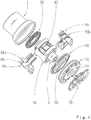
- eine perspektivische, teilweise geschnittene Darstellung des Ausführungsbeispiels unter Weglassung der Buchse und
- Figur 4
- eine perspektivische Explosionsdarstellung des Ausführungsbeispiels.
- Die Figuren zeigen ein Ausführungsbeispiel eines hydraulisch dämpfenden Buchsenlagers mit einer zu Bezugzeichen 2 gekennzeichneten Buchse, die konzentrisch zu einem Innenteil 4 angeordnet ist, welches die Buchse 2 durchsetzt. Die Buchse 2 hat auf einer mit Bezugzeichen 6 gekennzeichneten Anschlussseite einen vergrößerten Durchmesser und bildet im Grunde zwei Zylinderabschnitte aus, die über eine Anlageschulter 8 miteinander verbunden sind. Die durchmesserverbreitete Anschlussseite der Buchse 2 nimmt eine mit Bezugzeichen 10 gekennzeichnete axiale Lagermembran in sich auf, die an ihrem Außenumfang durch einen Haltering 12 und an ihrem Innenumfang durch einen Stützflansch 14 verstärkt ist. Der Haltering 12 und der Stützflansch 14 sind mit dem die Lagermembran 10 ausformenden elastomeren Material durch Vulkanisieren verbunden. Das so gebildete einteilige Lagermembranelement 16 ist in dem Ringspalt zwischen der Buchse 2 und dem Innenteil 4 eingepresst. Zusätzlich ist die Buchse 2 an ihrer Anschlagsseite umbördelt und übergreift den Haltering 12. Innerhalb dieser Umbördelung bildet die Lagermembran 10 an gegenüberliegenden Umfangsabschnitten jeweils einen Anschlagpuffer 18 aus, der von einer axialen Anschlagscheibe 20 überragt ist, die dem Innenteil 4 zugeordnet und mit diesem verbunden ist, und der an der Unterseite des Buchsenlagers axial wirkt. Die axiale Anschlagscheibe 20 liegt auf einem sich radial erstreckenden Ringabschnitt des Stützflansches 14 auf.
- Auf der Anschlagsschlussseite 6 gegenüberliegenden und mit Bezugszeichen 22 gekennzeichneten Oberseite ist die Buchse 2 durch eine axiale Gegenmembran 24 abgedeckt, die - wie die zuvor beschriebene Lagermembran 10 - ringförmig ausgeformt und radial innen durch einen Stützring 26 und radial außen durch einen Haltering 28 verstärkt ist. Auch an dieser Oberseite 22 befindet sich ein durch Vulkanisieren und Verbinden von Stützring 26, Halterring 28 und axiale Gegenmembran 24 ausgeformtes einheitliches Gegenmembranelement, welches einen oberen axialen Anschlagpuffer 30 ausbildet, welches in dem Ringspalt zwischen der Buchse 2 und dem Innenteil 4 in radialer Richtung verpresst ist. Das Innenteil 4 bildet eine Gegenmembrananlageschulter 32 aus, gegen welche das elastomere Material der Gegenmembran 24 unter der Presskraft des auf das Innenteil 4 aufgepressten Stützrings 26 dichtend anliegt.
- Axial innerhalb des oberen axialen Anschlagpuffers 30 und das Innenteil 4 umgebend ist ein elastomeres Dämpfungsglied 34 vorgesehen, welches aus einem elastomeren Material gebildet ist und in das ein aus einem Blechmaterial geformter Käfig 36 einvulkanisiert ist und radiale Kammerwände 35 ausbildet. Dieser Käfig 36 erstreckt sich im Wesentlichen über die gesamte axiale Erstreckung des elastomeren Dämpfungsgliedes 34. Wie insbesondere
Figur 2 zu entnehmen ist, verstärkt der Käfig 36 eine durch das elastomere Dämpfungsglied 34 gebildete Anlagefläche zur Anlage des Gegenmembranelementes 30 auf Höhe des Halterings 24, der durch eine Umbördelung der Buchse in axialer Richtung fixiert ist. Insofern ergibt sich eine solide Abdichtung zwischen dem elastomeren Dämpfungsglied 34 und dem Gegenmembranelement 30. An dieser Seite bildet das elastomere Dämpfungsglied ferner an in radialer Richtung gegenüberliegenden Seiten mit Bezugszeichen 38 gekennzeichnete Teilungen aus, deren Kontur der Kontur eines durch die Gegenmembran ausgeformten Ringkanals 40 entsprechen (vgl.Figur 1 ,Figur 3 ). Dementsprechend ist der Ringkanal 40 in Umfangsrichtung geteilt in zwei im Wesentlichen gleichgroße, erste Axialkammern 42, die als separate Axialkammern 42 a, 42 b inFigur 2 kenntlich gemacht sind. Diese Axialkammern 42 a, b erstrecken sich in Umfangsrichtung in etwa mit einem Winkel von 160 Grad. - Der Ringkanal 40 kommuniziert mit einer an dem stirnseitigen Ende des elastomeren Dämpfungsgliedes 34 ausgeformten Mulde 44, die wie der Ringkanal 40 durch die Teilung 38 in Umfangsabschnitte unterteilt ist. Die in Umfangsrichtung voneinander getrennten Muldenabschnitte gehören zu den beiden ersten Axialkammern 42 a, 42 b.
- Eine entsprechende Mulde 46 ist an der gegenüberliegenden Stirnseite des elastomeren Dämpfungsgliedes 34 ausgeformt. Diese Mulde 46 wird durch ein mit Bezugszeichen 48 gekennzeichnetes Zwischenmembranelement abgedeckt, welches eine sich im Wesentlichen in radialer Richtung erstreckende Zwischenmembran 50, einen Zwischenmembranstützring 52, eine einen Kern des Zwischenmembranelementes 48 bildende Ringscheibe 50 sowie mit Bezugszeichen 56 gekennzeichnete Anschlagselemente umfasst, die sich in Radialrichtung gegenüberliegen (vgl.
Figur 2 ). Zur Ausbildung des Zwischenmembranelementes wird zunächst der Zwischenmembranstützring 52 und die Ringscheibe 54 mit elastomerem Material umgeben, wobei eine Anlagefläche für die Anschlagselemente 56 freigelassen wird. Die Ringscheibe 54 wird dabei durch Abstandsnocken 60, die einteilig an der Ringscheibe 54 an radial gegenüberliegenden Bereichen ausgeformt sind, in einem Formwerkzeug positioniert (vgl.Figur 2 ) Nach dem Vulkanisieren des elastomeren Materials ist die Zwischenmembran 50 ausgeformt. Danach werden die Anschlagselemente 56 über die Stifte 58 mit der Ringscheibe 54 verbunden. Im montierten Zustand (vgl.Figur 2 ) ragen die Anschläge 56 in die Mulde 46 herein. - An seinem Außenumfang ist das Zwischenmembranelement 48 zwischen einer durch die Anschlagschulter 8 gebildeten inneren Ringfläche 62 der Buchse 2 und einer Stirnseite am Außenumfang des Lagermembranelementes 16 geklemmt. Auf Höhe der Abstandsnocken 60 ist die axiale Erstreckung des Halteringes 12 reduziert, so dass dieser dort mit dem elastomeren Material der Lagermembran 10 umgeben ist (vgl.
Figur 2 ). Ansonsten erstreckt sich der Haltering 12 in Umfangsrichtung axial bis zu der inneren Stirnseite des Lagermembranelementes 16. Der Haltering 12 klemmt die mit Elastomermaterial umgebene Ringscheibe 54 zwischen sich und der inneren Ringfläche 62 dichtend ein. Somit ist auf der Außenseite des Zwischenmembranelementes 48 eine als Pumpkammer wirkende Axialkammer 64 ausgeformt und dichtend abgeschlossen zwischen dem Zwischenmembranelement 48 und dem Lagermembranelement 16. - Zwischen dem Zwischenmembranstützring 52 und dem inneren Rand der Ringscheibe 54 bildet das Zwischenmembranelement 48 ein Ringkammersegment 66 aus, welches eine durch das Innenteil 4 ausgeformte anschlussseitige Stirnfläche 68 in axialer Richtung und in Richtung auf die Axialkammer 64 überragt und eine Ringkammer 70 umschließt, welche mit der Mulde 64 kommuniziert. Hierdurch ist eine flüssigkeitsleere Dämpfungskammer 72 gebildet, die in Umfangsrichtung umlaufend ausgeformt ist. Diese flüssigkeitsleere Dämpfungskammer 72 ist luftdicht abgeschlossen. Hierzu liegt das Zwischenmembranelement 48 mit der elastomeren Umhüllung der Ringscheibe 54 an einem mit Bezugszeichen 74 gekennzeichneten Anlagebereich des elastomeren Dämpfungsgliedes 34, welcher in axialer Richtung durch den Käfig 36 als Versteifungselement verstärkt ist, an. Radial innen erfolgt die Abdichtung durch den auf das Innenteil 4 aufpressten Zwischenmembranstützring 52, der zwischen sich und der anschlussseitigen Stirnfläche 68 das elastomere Material des Zwischenmembranelementes 48 dichtend einklemmt. Der Zwischenmembranstützring 52 bildet dabei mit dem damit aufvulkanisierten Elastomermaterial der Zwischenmembran 50 einen inneren Ringwandungsabschnitt 76 aus, der auf das Innenteil 4 hier aufgeschoben und verpresst ist und in axialer Richtung durch Anlage an der anschlussseitigen Stirnfläche 68 gegenüber dem Innenteil 4 festgelegt ist.
- Dabei ist die Zwischenmembran 50 derart ausgeformt, dass im zusammengebauten Zustand ein im Grunde durch die Ringscheibe 54 und deren elastomere Umhüllung gebildetes Dichtungssegment 78 des Zwischenmembranelementes 48 unter Vorspannung gegen den Anlagebereich 74 anliegt. Wäre das in dem Ausführungsbeispiel gezeigte Zwischenmembranelement für sich vorgesehen, würde aufgrund der Ausgestaltung der Zwischenmembran 50 das Dichtungssegment 78 die im zusammengebauten Zustand an der anschlussseitigen Stirnfläche 68 anliegende Stirnseite des Ringwandungsabschnitts 76 überragen, d.h. um einen Versatz vorspringen. Dieser Versatz wird beim Einbau des Zwischenmembranelementes 48 unter elastischer Vorspannung der flexiblen Wandungen des Ringkammersegmentes 66 vollständig aufgehoben, so dass die vordere Stirnseite des Ringwandungsabschnitts 76 in etwa höhengleich einer durch das Ringsegment 78 ausgeformten und mit dem Anlagebereich 74 des elastomeren Dämpfungsgliedes 34 zusammenwirkenden Dichtfläche 80 angeordnet wird. Durch diese axiale Vorspannung des Zwischenmembranelementes 48 wird die Dichtigkeit zwischen diesem Element 48 und dem elastomeren Dämpfungsglied 34 verbessert.
- Wie in den
Figuren 2 und3 zu entnehmen ist, bildet das elastomere Dämpfungsglied 34 an gegenüberliegenden Umfangsabschnitten radial einander gegenüberliegende Radialanschlagkonturen 82 aus, in denen sich mit Bezugszeichen 84 gekennzeichnete Zusatzelemente befinden, die aus einem Thermoplasten hergestellt sind. Das gezeigte Ausführungsbeispiel hat zwei Zusatzelemente 84 a, 84 b, die jeweils nach Art eines Halbringes ausgeformt und in derFigur 2 gezeigten Schnittebene miteinander gefügt sind. Die Zusatzelemente 84 liegen dichtend an der Innenumfangsfläche der Buchse 2 an und schließen dort einen mit Bezugszeichen 86 gekennzeichneten Radialkanal und einen mit Bezugszeichen 88 gekennzeichneten Axialkanal ein. InFigur 2 sind weiterhin innerhalb der Zusatzelemente 84 a, b kreisrunde Bohrungen zu erkennen. Dort sind die beiden Zusatzelemente 84 a, b durch Zapfen miteinander verbunden, so dass sich durch die beiden Zusatzelement 84 ein im Grunde zylindrisches Bauteil ergibt (VergleicheFigur 3 ). Zwischen den Radialanschlagkonturen 82 und der Innenumfangsfläche der Zusatzelemente 84 ist jeweils eine Radialkammer 90 eingeschlossen. Diese Radialkammern 90 a, 90 b kommunizieren über den Radialkanal 86 miteinander. Diese Ausgestaltung ist insbesondere inFigur 3 zu erkennen. Die Figur lässt auch den Verlauf des Axialkanals 88 erkennen, der durch einen zwischen wesentlichen in axialer Richtung erstreckenden Kanalabschnitt 88 a in die Pumpkammer 64 mündet, dann in einen sich nahezu vollumfänglich an der Außenseite der Zusatzelemente 84 erstreckenden Umfangsabschnitt 88 b übergeht. Am Ende dieses Umfangsabschnittes 88 b wird der Axialkanal 88 in zwei Kanalzweige 88 c, 88 d aufgeteilt, von denen der eine Kanalzweig 88 c in eine der ersten Axialkammern 42 a und der andere Kanalzweig 88 d in die andere der ersten Kanalkammern 42 b mündet. Dementsprechend ist jede der ersten Axialkammern 42 a, 42 b an der Lageroberseite 22 über den Axialkanal 88 mit der an der Anschlussseite 6 vorgesehenen Axialkammer 64 verbunden. - Praktische Versuche der Anmelderin haben ergeben, dass durch die Aufteilung die auf der einen Lageroberseite 22 vorgesehenen Axialkammer in mehrere unabhängige, in Umfangsrichtung getrennt voneinander vorgesehene Axialkammerteile 42 a, 42 b die Dämpfungseigenschaften des Lagers bei radialer Anregung verbessert werden können. Insbesondere erweist sich das Lager bei hohen Frequenzen als weniger steif. Dieser Effekt kann bei Bedarf noch durch eine entsprechende Teilung der auf der Anschlussseite 6 vorgesehenen Pumpkammer 64 erhöht werden. So ist es ohne weiteres denkbar, die Pumpkammer durch Teilungen in Umfangsrichtung in separate und voneinander getrennte Segmente zu unterteilen, die als Teil des Zwischenmembranelementes 48 aus dem elastomeren Material des Zwischenmembranelementes 48 ausgeformt sind und den zwischen diesem Element und dem Lagermembranelement 16 ausgebildeten Ringspalt beispielsweise in der Zeichnungsebene gemäß
Figur 1 durchsetzen. In einem solchen Fall würde auch der axiale Kanalabschnitt 88 a auf zwei Kanalzweige aufgeteilt und mit den entsprechenden einzelnen Pumpkammersegmenten verbunden. - Bei den gezeigten Ausführungsbeispielen sind die einzelnen Elemente lediglich durch Verpressen bzw. Umwirbeln miteinander verbunden. Insbesondere ist keine stoffschlüssige Verbindung zwischen dem elastomeren Dämpfungsglied 34 und dem Gegenmembranelement 30 bzw. dem Zwischenmembranelement 48 vorgesehen. Auch die Verbindung zwischen dem Zwischenmembranelement 48 und dem Lagermembranelement 16 ist keine stoffflüssige, sondern lediglich eine kraftschlüssige Verbindung.
- Die Zusatzelemente 84 begrenzen in an sich bekannter Weise die radiale Ausgleichsbewegung des Buchsenlagers und dienen dementsprechend als Radialanschlag. Der zuvor beschriebene untere axiale Anschlagpuffer 18 begrenzt eine etwaige Taumelbewegung der axialen Anschlagscheibe 20 relativ zu der Buchse 2.
-
- 2
- Buchse
- 4
- Innenteil
- 6
- Anschlussseite
- 8
- Anlageschulter
- 10
- Lagermembran, axial
- 12
- Haltering
- 14
- Stützflansch
- 16
- Lagermembranelement
- 18
- Anschlagpuffer, axial, unten
- 20
- Anschlagscheibe, axial
- 22
- Lageroberseite
- 24
- Gegenmembran
- 26
- Stützring
- 28
- Haltering
- 30
- Gegenmembranelement
- 32
- Gegenmembrananlageschulter
- 34
- Elastomeres Dämpfungsglied
- 35
- Radiale Kammerwand
- 36
- Käfig
- 38
- Teilung
- 40
- Ringkanal
- 42
- Erste Axialkammern
- 44
- Mulde
- 46
- Mulde
- 48
- Zwischenmembranelement
- 50
- Zwischenmembran
- 52
- Zwischenmembranstützring
- 54
- Ringscheibe
- 56
- Anschlagselement
- 58
- Stift
- 60
- Abstandsnocken
- 62
- Innere Ringfläche
- 64
- Axialkammer/Pumpkammer
- 66
- Ringkammersegment
- 68
- Anschlussseitige Stirnfläche
- 70
- Ringkammer
- 72
- Flüssigkeitsleere Dämpfungskammer
- 74
- Anlagebereich
- 76
- Ringwandungsabschnitt
- 78
- Dichtungssegment
- 80
- Dichtfläche
- 82
- Radialanschlagkontur
- 84
- Zusatzelement
- 84a
- Zusatzelement
- 84b
- Zusatzelement
- 86
- Radialkanal
- 88
- Axialkanal
- 88a
- axialer Kanalabschnitt
- 88b
- Umfangsabschnitt
- 88c
- Kanalzweig
- 88d
- Kanalzweig
- 90
- Radialkammer
Claims (9)
- Hydraulisch dämpfendes Buchsenlager mit einem länglichen Innenteil (4), einer Außenbuchse (2), einem zwischen der Außenbuchse (2) und dem Innenteil (4) angeordneten elastomeren Dämpfungsglied (34), einem Axialkammerpaar mit wenigstens zwei in axialer Richtung des Innenteils (4) versetzt zueinander angeordneten und miteinander über zumindest einen Axialkanal (88) kommunizierenden Axialkammern (42, 64), einem Radialkammerpaar mit wenigstens zwei, zwischen den Axialkammern (42, 64) angeordneten und in Umfangsrichtung des Innenteils versetzt angeordneten Radialkammern (90), die über wenigstens einen Radialkanal (86) kommunizieren, wobei zumindest auf einer Seite der Radialkammern zumindest zwei in Umfangsrichtung voneinander beabstandete und getrennte erste Axialkammern (42 a, 42 b) vorgesehen sind, dadurch gekennzeichnet, dass die ersten Axialkammern (42a, 42b) durch eine an dem elastomeren Dämpfungsglied (34) ausgeformte Teilung (38) voneinander getrennt sind, auf der eine die ersten Axialkammern (42a, 42b) begrenzende Gegenmembran (24) aufliegt.
- Hydraulisch dämpfendes Buchsenlager nach Anspruch 1, dadurch gekennzeichnet, dass zwischen den in axialer Richtung versetzt zueinander vorgesehenen Axialkammern (42, 64) wenigstens eine flüssigkeitsleere Dämpfungskammer (72) vorgesehen ist.
- Hydraulisch dämpfendes Buchsenlager nach Anspruch 2, dadurch gekennzeichnet, dass die flüssigkeitsleere Dämpfungskammer (72) in Umfangsrichtung durchgehend ausgebildet ist.
- Hydraulisch dämpfendes Buchsenlager nach Anspruch 2 oder 3, dadurch gekennzeichnet, dass die flüssigkeitsleere Dämpfungskammer (72) teilweise durch das elastomere Dämpfungsglied (34) und teilweise durch Wandungen eines auf das elastomere Dämpfungsglied (34) aufgesetzten Zwischenmembranelementes (48) begrenzt ist.
- Hydraulisch dämpfendes Buchsenlager nach Anspruch 4, dadurch gekennzeichnet, dass das Zwischenmembranelement (48) ein Ringkammersegment (66) zur Ausbildung einer Ringkammer (70) der flüssigkeitsleeren Dämpfungskammer (72) und ein dichtend an das elastomere Dämpfungsglied (34) anlegbares Dichtungssegment (78) ausformt.
- Hydraulisch dämpfendes Buchsenlager nach Anspruch 5, dadurch gekennzeichnet, dass das Zwischenmembranelement (48) derart ausgebildet ist, dass ein innerer Ringwandungsabschnitt (76) des Ringkammersegmentes (66) auf das Innenteil (4) aufschiebbar und in axialer Richtung gegenüber dem Innenteil (4) derart festgelegt ist, dass das Dichtungssegment (78) in einem ungespannten Ausgangszustand gegenüber einer Stirnseite des Ringwandungsabschnitts (76) in Richtung auf das elastomere Dämpfungsglied (34) mit einem Versatz vorspringt.
- Hydraulisch dämpfendes Buchsenlager nach Anspruch 5 oder 6, dadurch gekennzeichnet, dass das elastomere Dämpfungsglied (34) im Anlagebereich (74) der von dem Dichtungssegment (78) ausgebildeten Dichtfläche (80) mit wenigstens einem, sich im wesentlichen in axialer Richtung erstreckenden Versteifungselement (36) verstärkt ist.
- Hydraulisch dämpfendes Buchsenlager nach einem der Ansprüche 4 bis 7, gekennzeichnet durch wenigstens ein mit dem Zwischenmembranelement (48) verbundenes und mit dem elastomeren Dämpfungsglied (34) zusammenwirkendes Anschlagselement (56).
- Hydraulisch dämpfendes Buchsenlagen nach Anspruch 8, dadurch gekennzeichnet, dass das Anschlagselement (56) als separates Bauteil hergestellt und mit einer einen Kern des Zwischenmembranelementes bindenden Ringscheibe (54) verbunden ist.
Applications Claiming Priority (2)
| Application Number | Priority Date | Filing Date | Title |
|---|---|---|---|
| DE102012213446.8A DE102012213446A1 (de) | 2012-07-31 | 2012-07-31 | Hydraulisch dämpfendes Buchsenlager |
| PCT/EP2013/063798 WO2014019784A1 (de) | 2012-07-31 | 2013-07-01 | Hydraulisch dämpfendes buchsenlager |
Publications (2)
| Publication Number | Publication Date |
|---|---|
| EP2906852A1 EP2906852A1 (de) | 2015-08-19 |
| EP2906852B1 true EP2906852B1 (de) | 2019-05-01 |
Family
ID=48745938
Family Applications (1)
| Application Number | Title | Priority Date | Filing Date |
|---|---|---|---|
| EP13733287.0A Not-in-force EP2906852B1 (de) | 2012-07-31 | 2013-07-01 | Hydraulisch dämpfendes buchsenlager |
Country Status (5)
| Country | Link |
|---|---|
| US (1) | US9528566B2 (de) |
| EP (1) | EP2906852B1 (de) |
| CN (1) | CN104781576B (de) |
| DE (1) | DE102012213446A1 (de) |
| WO (1) | WO2014019784A1 (de) |
Cited By (1)
| Publication number | Priority date | Publication date | Assignee | Title |
|---|---|---|---|---|
| DE102023132495A1 (de) * | 2023-11-22 | 2025-05-22 | Sumitomo Riko Company Limited | Hydraulisches Lager und Verfahren zur Herstellung eines hydraulischen Lagers |
Families Citing this family (9)
| Publication number | Priority date | Publication date | Assignee | Title |
|---|---|---|---|---|
| DE102012213447A1 (de) * | 2012-07-31 | 2014-02-06 | Zf Friedrichshafen Ag | Hydraulisch dämpfendes Buchsenlager |
| DE102015108879A1 (de) * | 2015-06-04 | 2016-12-08 | Boge Elastmetall Gmbh | Elastomeres Buchsenlager |
| DE102016212485B4 (de) * | 2016-07-08 | 2018-01-18 | Contitech Vibration Control Gmbh | Buchse |
| CN206555347U (zh) * | 2016-12-02 | 2017-10-13 | 株洲时代新材料科技股份有限公司 | 一种轨道交通用液压衬套 |
| GB201805838D0 (en) * | 2018-04-09 | 2018-05-23 | Dtr Vms Ltd | Bush |
| DE102018113503A1 (de) * | 2018-06-06 | 2019-12-12 | Vibracoustic Gmbh | Aggregatelager |
| DE102019109212A1 (de) * | 2019-04-08 | 2020-10-08 | Vibracoustic Ag | Hydraulisch dämpfendes Lager |
| CN112649186B (zh) * | 2020-12-28 | 2023-07-21 | 齐重数控装备股份有限公司 | 一种数控重型卧式车床无动力尾座套筒部件模拟负载试运转方法 |
| US12366278B2 (en) * | 2021-08-18 | 2025-07-22 | Hyundai Motor Company | Fluid mount device for vehicle |
Family Cites Families (21)
| Publication number | Priority date | Publication date | Assignee | Title |
|---|---|---|---|---|
| JPH06103056B2 (ja) * | 1985-11-25 | 1994-12-14 | 日産自動車株式会社 | 防振装置 |
| DE3730582A1 (de) * | 1987-09-11 | 1989-03-23 | Opel Adam Ag | Lager zur elastischen, schwingungsdaempfenden lagerung von bauteilen |
| DE3909852A1 (de) * | 1988-09-26 | 1990-03-29 | Opel Adam Ag | Verspannbares, hydraulisch gedaempftes lagerelement |
| DE3933197A1 (de) * | 1989-10-05 | 1991-04-18 | Freudenberg Carl Fa | Hydraulisch gedaempfte huelsengummifeder |
| FR2659712B1 (fr) | 1990-03-16 | 1992-07-17 | Hutchinson | Perfectionnements apportes aux manchons antivibratoires hydrauliques. |
| DE4117129A1 (de) * | 1991-05-25 | 1992-11-26 | Daimler Benz Ag | Hydraulisch daempfendes lager |
| JPH0627638A (ja) | 1992-07-07 | 1994-02-04 | Hitachi Electron Eng Co Ltd | マスク板の位置合わせマーク |
| JPH06207638A (ja) * | 1993-01-12 | 1994-07-26 | Kurashiki Kako Co Ltd | 液体封入ブッシュ |
| DE19526750C2 (de) * | 1995-07-21 | 1998-07-02 | Metzeler Gimetall Ag | Axial dämpfende Hydrobuchse |
| DE19713003A1 (de) * | 1997-03-27 | 1998-10-01 | Lemfoerder Metallwaren Ag | Hülsengummifeder mit hydraulischer Dämpfung |
| JP2000104774A (ja) | 1998-09-25 | 2000-04-11 | Kurashiki Kako Co Ltd | 長寿命弾性構造体 |
| GB9913761D0 (en) * | 1999-06-14 | 1999-08-11 | Avon Vibration Man Syst Ltd | Hydraulically damped mounting device |
| DE10035024A1 (de) * | 2000-07-19 | 2002-01-31 | Daimler Chrysler Ag | Hydraulisch dämpfendes Elastomerlager |
| DE10035026A1 (de) * | 2000-07-19 | 2002-01-31 | Daimler Chrysler Ag | Hydraulisch dämpfendes Elastomerlager |
| FR2812363B1 (fr) | 2000-07-31 | 2003-01-17 | Hutchinson | Manchon antivibratoire hydraulique |
| US6698731B2 (en) | 2002-04-24 | 2004-03-02 | The Pullman Company | High compliance multiple chamber piston for fluid damped elastomer devices |
| US20060071379A1 (en) * | 2003-04-21 | 2006-04-06 | Akihiko Kato | Liquid-sealed vibration control device |
| DE10359340A1 (de) | 2003-12-16 | 2005-07-28 | Zf Friedrichshafen Ag | Hydraulisch dämpfendes Buchsenlager |
| FR2876429B1 (fr) * | 2004-10-11 | 2007-02-23 | Hutchinson Sa | Dispositif antivibratoire hydraulique pour vehicule et procede de fabrication d'un tel dispositif |
| JP5331329B2 (ja) * | 2007-12-05 | 2013-10-30 | 株式会社ブリヂストン | 液入り防振装置 |
| DE102012213447A1 (de) * | 2012-07-31 | 2014-02-06 | Zf Friedrichshafen Ag | Hydraulisch dämpfendes Buchsenlager |
-
2012
- 2012-07-31 DE DE102012213446.8A patent/DE102012213446A1/de not_active Withdrawn
-
2013
- 2013-07-01 CN CN201380048968.5A patent/CN104781576B/zh not_active Expired - Fee Related
- 2013-07-01 WO PCT/EP2013/063798 patent/WO2014019784A1/de not_active Ceased
- 2013-07-01 US US14/418,792 patent/US9528566B2/en not_active Expired - Fee Related
- 2013-07-01 EP EP13733287.0A patent/EP2906852B1/de not_active Not-in-force
Non-Patent Citations (1)
| Title |
|---|
| None * |
Cited By (2)
| Publication number | Priority date | Publication date | Assignee | Title |
|---|---|---|---|---|
| DE102023132495A1 (de) * | 2023-11-22 | 2025-05-22 | Sumitomo Riko Company Limited | Hydraulisches Lager und Verfahren zur Herstellung eines hydraulischen Lagers |
| DE102023132495B4 (de) | 2023-11-22 | 2026-04-16 | Sumitomo Riko Company Limited | Hydraulisches Lager und Verfahren zur Herstellung eines hydraulischen Lagers |
Also Published As
| Publication number | Publication date |
|---|---|
| CN104781576B (zh) | 2017-06-06 |
| US20150211598A1 (en) | 2015-07-30 |
| CN104781576A (zh) | 2015-07-15 |
| DE102012213446A1 (de) | 2014-02-06 |
| WO2014019784A1 (de) | 2014-02-06 |
| US9528566B2 (en) | 2016-12-27 |
| EP2906852A1 (de) | 2015-08-19 |
Similar Documents
| Publication | Publication Date | Title |
|---|---|---|
| EP2906851B1 (de) | Hydraulisch dämpfendes buchsenlager | |
| EP2906852B1 (de) | Hydraulisch dämpfendes buchsenlager | |
| DE102015007743B4 (de) | Schublager und druckluftbeaufschlagter Stoßdämpfer | |
| DE102016001507B4 (de) | Schwingungstilger | |
| DE3431460A1 (de) | Fluidgefuellte federnde buchsenkonstruktion | |
| EP1287273B1 (de) | Hydraulisch dämpfendes buchsenlager | |
| DE10131075A1 (de) | Aggregatelager in Buchsenform | |
| DE102010033811B4 (de) | Hydraulisch dämpfende Hydro-Lager für Achslenkerlager | |
| DE102013204995A1 (de) | Verfahren zum Herstellen eines Lagers und Lager | |
| DE3800656A1 (de) | Hydraulisch daempfende huelsengummifeder | |
| DE102007054902A1 (de) | Anschlagelement für Hydrolager und damit ausgestattete Hydrobuchse | |
| DE102016012731A1 (de) | Dämpfungskörper für eine obere Auflage | |
| DE112019003332T5 (de) | Fluidgefüllte vibrationsdämpfungsvorrichtung | |
| DE3445684A1 (de) | Schwingungsdaempfer fuer fahrzeuge | |
| EP0528253B1 (de) | Hydraulisch dämpfendes Stützlager für Fahrwerksteile in Kraftfahrzeugen | |
| EP2906850B1 (de) | Buchsenlager | |
| DE102006052917B4 (de) | Hydrolager mit Wegbegrenzung | |
| EP3953606A1 (de) | Hydraulisch dämpfendes lager | |
| DE102004014328B4 (de) | Hydraulisch dämpfendes Gummilager | |
| DE7904427U1 (de) | Hydraulisch dämpfendes Gummilager | |
| DE102006052918B4 (de) | Axial vorgespanntes Hydrolager | |
| EP2604884B1 (de) | Hydrolageranordnung und deren Verwendung | |
| DE102022113155B4 (de) | Elastomerlager mit Schutzkappe | |
| DE202006000820U1 (de) | Gelenklager, insbesondere zur Lagerung von Achslenkern in Kraftfahrzeugen | |
| DE102022128869A1 (de) | Vorrichtung zum Stützen eines Elastomerkörpers, hydraulisch dämpfendes Lager umfassend die Vorrichtung und Lageranordnung umfassend das Lager |
Legal Events
| Date | Code | Title | Description |
|---|---|---|---|
| PUAI | Public reference made under article 153(3) epc to a published international application that has entered the european phase |
Free format text: ORIGINAL CODE: 0009012 |
|
| 17P | Request for examination filed |
Effective date: 20150618 |
|
| AK | Designated contracting states |
Kind code of ref document: A1 Designated state(s): AL AT BE BG CH CY CZ DE DK EE ES FI FR GB GR HR HU IE IS IT LI LT LU LV MC MK MT NL NO PL PT RO RS SE SI SK SM TR |
|
| AX | Request for extension of the european patent |
Extension state: BA ME |
|
| DAX | Request for extension of the european patent (deleted) | ||
| RAP1 | Party data changed (applicant data changed or rights of an application transferred) |
Owner name: BOGE ELASTMETALL GMBH Owner name: AUDI AG |
|
| REG | Reference to a national code |
Ref country code: DE Ref legal event code: R079 Ref document number: 502013012752 Country of ref document: DE Free format text: PREVIOUS MAIN CLASS: F16F0013160000 Ipc: F16F0013140000 |
|
| GRAP | Despatch of communication of intention to grant a patent |
Free format text: ORIGINAL CODE: EPIDOSNIGR1 |
|
| STAA | Information on the status of an ep patent application or granted ep patent |
Free format text: STATUS: GRANT OF PATENT IS INTENDED |
|
| RIC1 | Information provided on ipc code assigned before grant |
Ipc: F16F 13/16 20060101ALI20181112BHEP Ipc: F16F 13/14 20060101AFI20181112BHEP Ipc: F16F 13/18 20060101ALI20181112BHEP |
|
| INTG | Intention to grant announced |
Effective date: 20181203 |
|
| GRAS | Grant fee paid |
Free format text: ORIGINAL CODE: EPIDOSNIGR3 |
|
| GRAA | (expected) grant |
Free format text: ORIGINAL CODE: 0009210 |
|
| STAA | Information on the status of an ep patent application or granted ep patent |
Free format text: STATUS: THE PATENT HAS BEEN GRANTED |
|
| AK | Designated contracting states |
Kind code of ref document: B1 Designated state(s): AL AT BE BG CH CY CZ DE DK EE ES FI FR GB GR HR HU IE IS IT LI LT LU LV MC MK MT NL NO PL PT RO RS SE SI SK SM TR |
|
| REG | Reference to a national code |
Ref country code: GB Ref legal event code: FG4D Free format text: NOT ENGLISH |
|
| REG | Reference to a national code |
Ref country code: CH Ref legal event code: EP Ref country code: AT Ref legal event code: REF Ref document number: 1127345 Country of ref document: AT Kind code of ref document: T Effective date: 20190515 |
|
| REG | Reference to a national code |
Ref country code: DE Ref legal event code: R096 Ref document number: 502013012752 Country of ref document: DE |
|
| REG | Reference to a national code |
Ref country code: IE Ref legal event code: FG4D Free format text: LANGUAGE OF EP DOCUMENT: GERMAN |
|
| REG | Reference to a national code |
Ref country code: NL Ref legal event code: MP Effective date: 20190501 |
|
| REG | Reference to a national code |
Ref country code: LT Ref legal event code: MG4D |
|
| PG25 | Lapsed in a contracting state [announced via postgrant information from national office to epo] |
Ref country code: NO Free format text: LAPSE BECAUSE OF FAILURE TO SUBMIT A TRANSLATION OF THE DESCRIPTION OR TO PAY THE FEE WITHIN THE PRESCRIBED TIME-LIMIT Effective date: 20190801 Ref country code: LT Free format text: LAPSE BECAUSE OF FAILURE TO SUBMIT A TRANSLATION OF THE DESCRIPTION OR TO PAY THE FEE WITHIN THE PRESCRIBED TIME-LIMIT Effective date: 20190501 Ref country code: ES Free format text: LAPSE BECAUSE OF FAILURE TO SUBMIT A TRANSLATION OF THE DESCRIPTION OR TO PAY THE FEE WITHIN THE PRESCRIBED TIME-LIMIT Effective date: 20190501 Ref country code: SE Free format text: LAPSE BECAUSE OF FAILURE TO SUBMIT A TRANSLATION OF THE DESCRIPTION OR TO PAY THE FEE WITHIN THE PRESCRIBED TIME-LIMIT Effective date: 20190501 Ref country code: NL Free format text: LAPSE BECAUSE OF FAILURE TO SUBMIT A TRANSLATION OF THE DESCRIPTION OR TO PAY THE FEE WITHIN THE PRESCRIBED TIME-LIMIT Effective date: 20190501 Ref country code: HR Free format text: LAPSE BECAUSE OF FAILURE TO SUBMIT A TRANSLATION OF THE DESCRIPTION OR TO PAY THE FEE WITHIN THE PRESCRIBED TIME-LIMIT Effective date: 20190501 Ref country code: PT Free format text: LAPSE BECAUSE OF FAILURE TO SUBMIT A TRANSLATION OF THE DESCRIPTION OR TO PAY THE FEE WITHIN THE PRESCRIBED TIME-LIMIT Effective date: 20190901 Ref country code: AL Free format text: LAPSE BECAUSE OF FAILURE TO SUBMIT A TRANSLATION OF THE DESCRIPTION OR TO PAY THE FEE WITHIN THE PRESCRIBED TIME-LIMIT Effective date: 20190501 Ref country code: FI Free format text: LAPSE BECAUSE OF FAILURE TO SUBMIT A TRANSLATION OF THE DESCRIPTION OR TO PAY THE FEE WITHIN THE PRESCRIBED TIME-LIMIT Effective date: 20190501 |
|
| PG25 | Lapsed in a contracting state [announced via postgrant information from national office to epo] |
Ref country code: LV Free format text: LAPSE BECAUSE OF FAILURE TO SUBMIT A TRANSLATION OF THE DESCRIPTION OR TO PAY THE FEE WITHIN THE PRESCRIBED TIME-LIMIT Effective date: 20190501 Ref country code: GR Free format text: LAPSE BECAUSE OF FAILURE TO SUBMIT A TRANSLATION OF THE DESCRIPTION OR TO PAY THE FEE WITHIN THE PRESCRIBED TIME-LIMIT Effective date: 20190802 Ref country code: RS Free format text: LAPSE BECAUSE OF FAILURE TO SUBMIT A TRANSLATION OF THE DESCRIPTION OR TO PAY THE FEE WITHIN THE PRESCRIBED TIME-LIMIT Effective date: 20190501 Ref country code: BG Free format text: LAPSE BECAUSE OF FAILURE TO SUBMIT A TRANSLATION OF THE DESCRIPTION OR TO PAY THE FEE WITHIN THE PRESCRIBED TIME-LIMIT Effective date: 20190801 |
|
| PG25 | Lapsed in a contracting state [announced via postgrant information from national office to epo] |
Ref country code: IS Free format text: LAPSE BECAUSE OF FAILURE TO SUBMIT A TRANSLATION OF THE DESCRIPTION OR TO PAY THE FEE WITHIN THE PRESCRIBED TIME-LIMIT Effective date: 20190901 |
|
| PG25 | Lapsed in a contracting state [announced via postgrant information from national office to epo] |
Ref country code: CZ Free format text: LAPSE BECAUSE OF FAILURE TO SUBMIT A TRANSLATION OF THE DESCRIPTION OR TO PAY THE FEE WITHIN THE PRESCRIBED TIME-LIMIT Effective date: 20190501 Ref country code: RO Free format text: LAPSE BECAUSE OF FAILURE TO SUBMIT A TRANSLATION OF THE DESCRIPTION OR TO PAY THE FEE WITHIN THE PRESCRIBED TIME-LIMIT Effective date: 20190501 Ref country code: SK Free format text: LAPSE BECAUSE OF FAILURE TO SUBMIT A TRANSLATION OF THE DESCRIPTION OR TO PAY THE FEE WITHIN THE PRESCRIBED TIME-LIMIT Effective date: 20190501 Ref country code: DK Free format text: LAPSE BECAUSE OF FAILURE TO SUBMIT A TRANSLATION OF THE DESCRIPTION OR TO PAY THE FEE WITHIN THE PRESCRIBED TIME-LIMIT Effective date: 20190501 Ref country code: EE Free format text: LAPSE BECAUSE OF FAILURE TO SUBMIT A TRANSLATION OF THE DESCRIPTION OR TO PAY THE FEE WITHIN THE PRESCRIBED TIME-LIMIT Effective date: 20190501 |
|
| REG | Reference to a national code |
Ref country code: DE Ref legal event code: R097 Ref document number: 502013012752 Country of ref document: DE |
|
| PG25 | Lapsed in a contracting state [announced via postgrant information from national office to epo] |
Ref country code: MC Free format text: LAPSE BECAUSE OF FAILURE TO SUBMIT A TRANSLATION OF THE DESCRIPTION OR TO PAY THE FEE WITHIN THE PRESCRIBED TIME-LIMIT Effective date: 20190501 Ref country code: SM Free format text: LAPSE BECAUSE OF FAILURE TO SUBMIT A TRANSLATION OF THE DESCRIPTION OR TO PAY THE FEE WITHIN THE PRESCRIBED TIME-LIMIT Effective date: 20190501 |
|
| REG | Reference to a national code |
Ref country code: CH Ref legal event code: PL |
|
| PLBE | No opposition filed within time limit |
Free format text: ORIGINAL CODE: 0009261 |
|
| STAA | Information on the status of an ep patent application or granted ep patent |
Free format text: STATUS: NO OPPOSITION FILED WITHIN TIME LIMIT |
|
| PG25 | Lapsed in a contracting state [announced via postgrant information from national office to epo] |
Ref country code: TR Free format text: LAPSE BECAUSE OF FAILURE TO SUBMIT A TRANSLATION OF THE DESCRIPTION OR TO PAY THE FEE WITHIN THE PRESCRIBED TIME-LIMIT Effective date: 20190501 |
|
| 26N | No opposition filed |
Effective date: 20200204 |
|
| REG | Reference to a national code |
Ref country code: BE Ref legal event code: MM Effective date: 20190731 |
|
| GBPC | Gb: european patent ceased through non-payment of renewal fee |
Effective date: 20190801 |
|
| PG25 | Lapsed in a contracting state [announced via postgrant information from national office to epo] |
Ref country code: PL Free format text: LAPSE BECAUSE OF FAILURE TO SUBMIT A TRANSLATION OF THE DESCRIPTION OR TO PAY THE FEE WITHIN THE PRESCRIBED TIME-LIMIT Effective date: 20190501 |
|
| PG25 | Lapsed in a contracting state [announced via postgrant information from national office to epo] |
Ref country code: SI Free format text: LAPSE BECAUSE OF FAILURE TO SUBMIT A TRANSLATION OF THE DESCRIPTION OR TO PAY THE FEE WITHIN THE PRESCRIBED TIME-LIMIT Effective date: 20190501 Ref country code: BE Free format text: LAPSE BECAUSE OF NON-PAYMENT OF DUE FEES Effective date: 20190731 Ref country code: LI Free format text: LAPSE BECAUSE OF NON-PAYMENT OF DUE FEES Effective date: 20190731 Ref country code: LU Free format text: LAPSE BECAUSE OF NON-PAYMENT OF DUE FEES Effective date: 20190701 Ref country code: CH Free format text: LAPSE BECAUSE OF NON-PAYMENT OF DUE FEES Effective date: 20190731 |
|
| PG25 | Lapsed in a contracting state [announced via postgrant information from national office to epo] |
Ref country code: IE Free format text: LAPSE BECAUSE OF NON-PAYMENT OF DUE FEES Effective date: 20190701 |
|
| PG25 | Lapsed in a contracting state [announced via postgrant information from national office to epo] |
Ref country code: GB Free format text: LAPSE BECAUSE OF NON-PAYMENT OF DUE FEES Effective date: 20190801 |
|
| REG | Reference to a national code |
Ref country code: AT Ref legal event code: MM01 Ref document number: 1127345 Country of ref document: AT Kind code of ref document: T Effective date: 20190701 |
|
| PGFP | Annual fee paid to national office [announced via postgrant information from national office to epo] |
Ref country code: FR Payment date: 20200717 Year of fee payment: 8 |
|
| PG25 | Lapsed in a contracting state [announced via postgrant information from national office to epo] |
Ref country code: AT Free format text: LAPSE BECAUSE OF NON-PAYMENT OF DUE FEES Effective date: 20190701 |
|
| PGFP | Annual fee paid to national office [announced via postgrant information from national office to epo] |
Ref country code: IT Payment date: 20200731 Year of fee payment: 8 |
|
| PG25 | Lapsed in a contracting state [announced via postgrant information from national office to epo] |
Ref country code: CY Free format text: LAPSE BECAUSE OF FAILURE TO SUBMIT A TRANSLATION OF THE DESCRIPTION OR TO PAY THE FEE WITHIN THE PRESCRIBED TIME-LIMIT Effective date: 20190501 |
|
| PG25 | Lapsed in a contracting state [announced via postgrant information from national office to epo] |
Ref country code: MT Free format text: LAPSE BECAUSE OF FAILURE TO SUBMIT A TRANSLATION OF THE DESCRIPTION OR TO PAY THE FEE WITHIN THE PRESCRIBED TIME-LIMIT Effective date: 20190501 Ref country code: HU Free format text: LAPSE BECAUSE OF FAILURE TO SUBMIT A TRANSLATION OF THE DESCRIPTION OR TO PAY THE FEE WITHIN THE PRESCRIBED TIME-LIMIT; INVALID AB INITIO Effective date: 20130701 |
|
| PG25 | Lapsed in a contracting state [announced via postgrant information from national office to epo] |
Ref country code: FR Free format text: LAPSE BECAUSE OF NON-PAYMENT OF DUE FEES Effective date: 20210731 |
|
| PG25 | Lapsed in a contracting state [announced via postgrant information from national office to epo] |
Ref country code: MK Free format text: LAPSE BECAUSE OF FAILURE TO SUBMIT A TRANSLATION OF THE DESCRIPTION OR TO PAY THE FEE WITHIN THE PRESCRIBED TIME-LIMIT Effective date: 20190501 |
|
| PG25 | Lapsed in a contracting state [announced via postgrant information from national office to epo] |
Ref country code: IT Free format text: LAPSE BECAUSE OF NON-PAYMENT OF DUE FEES Effective date: 20210701 |
|
| PGFP | Annual fee paid to national office [announced via postgrant information from national office to epo] |
Ref country code: DE Payment date: 20220714 Year of fee payment: 10 |
|
| P01 | Opt-out of the competence of the unified patent court (upc) registered |
Effective date: 20230530 |
|
| REG | Reference to a national code |
Ref country code: DE Ref legal event code: R119 Ref document number: 502013012752 Country of ref document: DE |
|
| PG25 | Lapsed in a contracting state [announced via postgrant information from national office to epo] |
Ref country code: DE Free format text: LAPSE BECAUSE OF NON-PAYMENT OF DUE FEES Effective date: 20240201 |