EP3317036B1 - Contenant en métal réfractaire - Google Patents
Contenant en métal réfractaire Download PDFInfo
- Publication number
- EP3317036B1 EP3317036B1 EP16741842.5A EP16741842A EP3317036B1 EP 3317036 B1 EP3317036 B1 EP 3317036B1 EP 16741842 A EP16741842 A EP 16741842A EP 3317036 B1 EP3317036 B1 EP 3317036B1
- Authority
- EP
- European Patent Office
- Prior art keywords
- container
- parts
- refractory metal
- spraying
- sprayed layer
- Prior art date
- Legal status (The legal status is an assumption and is not a legal conclusion. Google has not performed a legal analysis and makes no representation as to the accuracy of the status listed.)
- Active
Links
- 239000003870 refractory metal Substances 0.000 title claims description 48
- 238000000034 method Methods 0.000 claims description 39
- 238000005507 spraying Methods 0.000 claims description 33
- 238000004519 manufacturing process Methods 0.000 claims description 18
- 238000007750 plasma spraying Methods 0.000 claims description 15
- 229910001092 metal group alloy Inorganic materials 0.000 claims description 12
- ZOKXTWBITQBERF-UHFFFAOYSA-N Molybdenum Chemical compound [Mo] ZOKXTWBITQBERF-UHFFFAOYSA-N 0.000 claims description 11
- 239000000843 powder Substances 0.000 claims description 11
- WFKWXMTUELFFGS-UHFFFAOYSA-N tungsten Chemical compound [W] WFKWXMTUELFFGS-UHFFFAOYSA-N 0.000 claims description 11
- 239000011733 molybdenum Substances 0.000 claims description 10
- 229910052721 tungsten Inorganic materials 0.000 claims description 10
- 239000010937 tungsten Substances 0.000 claims description 10
- 229910052750 molybdenum Inorganic materials 0.000 claims description 9
- 239000000919 ceramic Substances 0.000 claims description 8
- 238000010285 flame spraying Methods 0.000 claims description 5
- 238000005245 sintering Methods 0.000 claims description 5
- 238000007751 thermal spraying Methods 0.000 claims description 5
- 238000003825 pressing Methods 0.000 claims description 4
- 238000010283 detonation spraying Methods 0.000 claims description 3
- 238000001513 hot isostatic pressing Methods 0.000 claims description 3
- 239000002002 slurry Substances 0.000 claims description 3
- 238000010891 electric arc Methods 0.000 claims description 2
- 238000000137 annealing Methods 0.000 claims 1
- 238000009740 moulding (composite fabrication) Methods 0.000 claims 1
- 239000010410 layer Substances 0.000 description 61
- 239000000463 material Substances 0.000 description 46
- MCMNRKCIXSYSNV-UHFFFAOYSA-N Zirconium dioxide Chemical compound O=[Zr]=O MCMNRKCIXSYSNV-UHFFFAOYSA-N 0.000 description 24
- GWEVSGVZZGPLCZ-UHFFFAOYSA-N Titan oxide Chemical compound O=[Ti]=O GWEVSGVZZGPLCZ-UHFFFAOYSA-N 0.000 description 20
- 239000011651 chromium Substances 0.000 description 19
- 239000010955 niobium Substances 0.000 description 19
- 239000007921 spray Substances 0.000 description 13
- 229910018072 Al 2 O 3 Inorganic materials 0.000 description 12
- 238000007789 sealing Methods 0.000 description 12
- 239000002245 particle Substances 0.000 description 11
- 229910010413 TiO 2 Inorganic materials 0.000 description 10
- PNEYBMLMFCGWSK-UHFFFAOYSA-N aluminium oxide Inorganic materials [O-2].[O-2].[O-2].[Al+3].[Al+3] PNEYBMLMFCGWSK-UHFFFAOYSA-N 0.000 description 10
- 229910052593 corundum Inorganic materials 0.000 description 10
- CJNBYAVZURUTKZ-UHFFFAOYSA-N hafnium(IV) oxide Inorganic materials O=[Hf]=O CJNBYAVZURUTKZ-UHFFFAOYSA-N 0.000 description 10
- 238000002844 melting Methods 0.000 description 10
- 229910001404 rare earth metal oxide Inorganic materials 0.000 description 10
- 229910001845 yogo sapphire Inorganic materials 0.000 description 10
- RUDFQVOCFDJEEF-UHFFFAOYSA-N yttrium(III) oxide Inorganic materials [O-2].[O-2].[O-2].[Y+3].[Y+3] RUDFQVOCFDJEEF-UHFFFAOYSA-N 0.000 description 10
- 239000007789 gas Substances 0.000 description 9
- 239000000155 melt Substances 0.000 description 9
- 230000008018 melting Effects 0.000 description 9
- 238000000576 coating method Methods 0.000 description 8
- 238000003801 milling Methods 0.000 description 8
- 229910001080 W alloy Inorganic materials 0.000 description 7
- 238000003466 welding Methods 0.000 description 7
- 230000007797 corrosion Effects 0.000 description 6
- 238000005260 corrosion Methods 0.000 description 6
- 229910052751 metal Inorganic materials 0.000 description 6
- 239000002184 metal Substances 0.000 description 6
- 239000011148 porous material Substances 0.000 description 6
- HYXGAEYDKFCVMU-UHFFFAOYSA-N scandium(III) oxide Inorganic materials O=[Sc]O[Sc]=O HYXGAEYDKFCVMU-UHFFFAOYSA-N 0.000 description 6
- 229910045601 alloy Inorganic materials 0.000 description 5
- 239000000956 alloy Substances 0.000 description 5
- TWNQGVIAIRXVLR-UHFFFAOYSA-N oxo(oxoalumanyloxy)alumane Chemical compound O=[Al]O[Al]=O TWNQGVIAIRXVLR-UHFFFAOYSA-N 0.000 description 5
- 229910052720 vanadium Inorganic materials 0.000 description 5
- 229910000599 Cr alloy Inorganic materials 0.000 description 4
- 229910001257 Nb alloy Inorganic materials 0.000 description 4
- 229910000691 Re alloy Inorganic materials 0.000 description 4
- 229910001362 Ta alloys Inorganic materials 0.000 description 4
- 239000011248 coating agent Substances 0.000 description 4
- 238000000227 grinding Methods 0.000 description 4
- 230000001939 inductive effect Effects 0.000 description 4
- 230000035515 penetration Effects 0.000 description 4
- 239000000758 substrate Substances 0.000 description 4
- 238000010290 vacuum plasma spraying Methods 0.000 description 4
- 229910052727 yttrium Inorganic materials 0.000 description 4
- 239000013078 crystal Substances 0.000 description 3
- 230000000694 effects Effects 0.000 description 3
- 238000005304 joining Methods 0.000 description 3
- 150000002739 metals Chemical class 0.000 description 3
- 230000001681 protective effect Effects 0.000 description 3
- XKRFYHLGVUSROY-UHFFFAOYSA-N Argon Chemical compound [Ar] XKRFYHLGVUSROY-UHFFFAOYSA-N 0.000 description 2
- 239000008000 CHES buffer Substances 0.000 description 2
- VYZAMTAEIAYCRO-UHFFFAOYSA-N Chromium Chemical compound [Cr] VYZAMTAEIAYCRO-UHFFFAOYSA-N 0.000 description 2
- 238000002231 Czochralski process Methods 0.000 description 2
- MKWKNSIESPFAQN-UHFFFAOYSA-N N-cyclohexyl-2-aminoethanesulfonic acid Chemical compound OS(=O)(=O)CCNC1CCCCC1 MKWKNSIESPFAQN-UHFFFAOYSA-N 0.000 description 2
- 238000005452 bending Methods 0.000 description 2
- 229910052804 chromium Inorganic materials 0.000 description 2
- 238000007796 conventional method Methods 0.000 description 2
- 230000006378 damage Effects 0.000 description 2
- 238000009792 diffusion process Methods 0.000 description 2
- 239000011521 glass Substances 0.000 description 2
- 230000005484 gravity Effects 0.000 description 2
- 238000010438 heat treatment Methods 0.000 description 2
- 238000002347 injection Methods 0.000 description 2
- 239000007924 injection Substances 0.000 description 2
- 238000001746 injection moulding Methods 0.000 description 2
- 229910052740 iodine Inorganic materials 0.000 description 2
- 229910052758 niobium Inorganic materials 0.000 description 2
- GUCVJGMIXFAOAE-UHFFFAOYSA-N niobium atom Chemical compound [Nb] GUCVJGMIXFAOAE-UHFFFAOYSA-N 0.000 description 2
- 229910052574 oxide ceramic Inorganic materials 0.000 description 2
- 239000011224 oxide ceramic Substances 0.000 description 2
- 230000000737 periodic effect Effects 0.000 description 2
- 238000004663 powder metallurgy Methods 0.000 description 2
- 229910052702 rhenium Inorganic materials 0.000 description 2
- WUAPFZMCVAUBPE-UHFFFAOYSA-N rhenium atom Chemical compound [Re] WUAPFZMCVAUBPE-UHFFFAOYSA-N 0.000 description 2
- 238000005096 rolling process Methods 0.000 description 2
- 229910052594 sapphire Inorganic materials 0.000 description 2
- 239000010980 sapphire Substances 0.000 description 2
- 238000007493 shaping process Methods 0.000 description 2
- 229910052715 tantalum Inorganic materials 0.000 description 2
- GUVRBAGPIYLISA-UHFFFAOYSA-N tantalum atom Chemical compound [Ta] GUVRBAGPIYLISA-UHFFFAOYSA-N 0.000 description 2
- 239000010936 titanium Substances 0.000 description 2
- GPPXJZIENCGNKB-UHFFFAOYSA-N vanadium Chemical compound [V]#[V] GPPXJZIENCGNKB-UHFFFAOYSA-N 0.000 description 2
- OYPRJOBELJOOCE-UHFFFAOYSA-N Calcium Chemical compound [Ca] OYPRJOBELJOOCE-UHFFFAOYSA-N 0.000 description 1
- 229910021193 La 2 O 3 Inorganic materials 0.000 description 1
- FYYHWMGAXLPEAU-UHFFFAOYSA-N Magnesium Chemical compound [Mg] FYYHWMGAXLPEAU-UHFFFAOYSA-N 0.000 description 1
- 229910001182 Mo alloy Inorganic materials 0.000 description 1
- RTAQQCXQSZGOHL-UHFFFAOYSA-N Titanium Chemical compound [Ti] RTAQQCXQSZGOHL-UHFFFAOYSA-N 0.000 description 1
- QCWXUUIWCKQGHC-UHFFFAOYSA-N Zirconium Chemical compound [Zr] QCWXUUIWCKQGHC-UHFFFAOYSA-N 0.000 description 1
- 238000010521 absorption reaction Methods 0.000 description 1
- 230000002411 adverse Effects 0.000 description 1
- 229910052782 aluminium Inorganic materials 0.000 description 1
- XAGFODPZIPBFFR-UHFFFAOYSA-N aluminium Chemical compound [Al] XAGFODPZIPBFFR-UHFFFAOYSA-N 0.000 description 1
- 229910052786 argon Inorganic materials 0.000 description 1
- QVGXLLKOCUKJST-UHFFFAOYSA-N atomic oxygen Chemical compound [O] QVGXLLKOCUKJST-UHFFFAOYSA-N 0.000 description 1
- 230000015572 biosynthetic process Effects 0.000 description 1
- 229910052791 calcium Inorganic materials 0.000 description 1
- 239000011575 calcium Substances 0.000 description 1
- 238000006243 chemical reaction Methods 0.000 description 1
- 238000005056 compaction Methods 0.000 description 1
- 150000001875 compounds Chemical class 0.000 description 1
- 238000011109 contamination Methods 0.000 description 1
- 229910052802 copper Inorganic materials 0.000 description 1
- 230000007547 defect Effects 0.000 description 1
- 230000001419 dependent effect Effects 0.000 description 1
- 238000013461 design Methods 0.000 description 1
- 238000009826 distribution Methods 0.000 description 1
- 238000010894 electron beam technology Methods 0.000 description 1
- 238000004049 embossing Methods 0.000 description 1
- 238000005516 engineering process Methods 0.000 description 1
- 210000003746 feather Anatomy 0.000 description 1
- 239000000945 filler Substances 0.000 description 1
- 229910052735 hafnium Inorganic materials 0.000 description 1
- VBJZVLUMGGDVMO-UHFFFAOYSA-N hafnium atom Chemical compound [Hf] VBJZVLUMGGDVMO-UHFFFAOYSA-N 0.000 description 1
- 239000012535 impurity Substances 0.000 description 1
- 229910000816 inconels 718 Inorganic materials 0.000 description 1
- MRELNEQAGSRDBK-UHFFFAOYSA-N lanthanum oxide Inorganic materials [O-2].[O-2].[O-2].[La+3].[La+3] MRELNEQAGSRDBK-UHFFFAOYSA-N 0.000 description 1
- 230000007774 longterm Effects 0.000 description 1
- 229910052749 magnesium Inorganic materials 0.000 description 1
- 239000011777 magnesium Substances 0.000 description 1
- 238000011089 mechanical engineering Methods 0.000 description 1
- 238000010309 melting process Methods 0.000 description 1
- 239000000203 mixture Substances 0.000 description 1
- MGRWKWACZDFZJT-UHFFFAOYSA-N molybdenum tungsten Chemical compound [Mo].[W] MGRWKWACZDFZJT-UHFFFAOYSA-N 0.000 description 1
- 238000000879 optical micrograph Methods 0.000 description 1
- 230000003647 oxidation Effects 0.000 description 1
- 238000007254 oxidation reaction Methods 0.000 description 1
- -1 oxides Chemical class 0.000 description 1
- KTUFCUMIWABKDW-UHFFFAOYSA-N oxo(oxolanthaniooxy)lanthanum Chemical compound O=[La]O[La]=O KTUFCUMIWABKDW-UHFFFAOYSA-N 0.000 description 1
- 239000001301 oxygen Substances 0.000 description 1
- 229910052760 oxygen Inorganic materials 0.000 description 1
- 235000012771 pancakes Nutrition 0.000 description 1
- 230000008092 positive effect Effects 0.000 description 1
- 238000007781 pre-processing Methods 0.000 description 1
- 238000012545 processing Methods 0.000 description 1
- 239000011241 protective layer Substances 0.000 description 1
- 229910052761 rare earth metal Inorganic materials 0.000 description 1
- 150000002910 rare earth metals Chemical class 0.000 description 1
- 150000003839 salts Chemical class 0.000 description 1
- 229910052706 scandium Inorganic materials 0.000 description 1
- SIXSYDAISGFNSX-UHFFFAOYSA-N scandium atom Chemical compound [Sc] SIXSYDAISGFNSX-UHFFFAOYSA-N 0.000 description 1
- 238000001878 scanning electron micrograph Methods 0.000 description 1
- 238000005204 segregation Methods 0.000 description 1
- IHQKEDIOMGYHEB-UHFFFAOYSA-M sodium dimethylarsinate Chemical class [Na+].C[As](C)([O-])=O IHQKEDIOMGYHEB-UHFFFAOYSA-M 0.000 description 1
- 229910052712 strontium Inorganic materials 0.000 description 1
- CIOAGBVUUVVLOB-UHFFFAOYSA-N strontium atom Chemical compound [Sr] CIOAGBVUUVVLOB-UHFFFAOYSA-N 0.000 description 1
- 239000000126 substance Substances 0.000 description 1
- 229910000601 superalloy Inorganic materials 0.000 description 1
- 238000012360 testing method Methods 0.000 description 1
- 229910052719 titanium Inorganic materials 0.000 description 1
- 238000012546 transfer Methods 0.000 description 1
- 230000009466 transformation Effects 0.000 description 1
- VWQVUPCCIRVNHF-UHFFFAOYSA-N yttrium atom Chemical compound [Y] VWQVUPCCIRVNHF-UHFFFAOYSA-N 0.000 description 1
- 229910052726 zirconium Inorganic materials 0.000 description 1
Images
Classifications
-
- B—PERFORMING OPERATIONS; TRANSPORTING
- B22—CASTING; POWDER METALLURGY
- B22F—WORKING METALLIC POWDER; MANUFACTURE OF ARTICLES FROM METALLIC POWDER; MAKING METALLIC POWDER; APPARATUS OR DEVICES SPECIALLY ADAPTED FOR METALLIC POWDER
- B22F5/00—Manufacture of workpieces or articles from metallic powder characterised by the special shape of the product
- B22F5/007—Manufacture of workpieces or articles from metallic powder characterised by the special shape of the product of moulds
-
- C—CHEMISTRY; METALLURGY
- C23—COATING METALLIC MATERIAL; COATING MATERIAL WITH METALLIC MATERIAL; CHEMICAL SURFACE TREATMENT; DIFFUSION TREATMENT OF METALLIC MATERIAL; COATING BY VACUUM EVAPORATION, BY SPUTTERING, BY ION IMPLANTATION OR BY CHEMICAL VAPOUR DEPOSITION, IN GENERAL; INHIBITING CORROSION OF METALLIC MATERIAL OR INCRUSTATION IN GENERAL
- C23C—COATING METALLIC MATERIAL; COATING MATERIAL WITH METALLIC MATERIAL; SURFACE TREATMENT OF METALLIC MATERIAL BY DIFFUSION INTO THE SURFACE, BY CHEMICAL CONVERSION OR SUBSTITUTION; COATING BY VACUUM EVAPORATION, BY SPUTTERING, BY ION IMPLANTATION OR BY CHEMICAL VAPOUR DEPOSITION, IN GENERAL
- C23C4/00—Coating by spraying the coating material in the molten state, e.g. by flame, plasma or electric discharge
-
- B—PERFORMING OPERATIONS; TRANSPORTING
- B22—CASTING; POWDER METALLURGY
- B22D—CASTING OF METALS; CASTING OF OTHER SUBSTANCES BY THE SAME PROCESSES OR DEVICES
- B22D33/00—Equipment for handling moulds
- B22D33/04—Bringing together or separating moulds
-
- B—PERFORMING OPERATIONS; TRANSPORTING
- B22—CASTING; POWDER METALLURGY
- B22D—CASTING OF METALS; CASTING OF OTHER SUBSTANCES BY THE SAME PROCESSES OR DEVICES
- B22D41/00—Casting melt-holding vessels, e.g. ladles, tundishes, cups or the like
-
- B—PERFORMING OPERATIONS; TRANSPORTING
- B22—CASTING; POWDER METALLURGY
- B22F—WORKING METALLIC POWDER; MANUFACTURE OF ARTICLES FROM METALLIC POWDER; MAKING METALLIC POWDER; APPARATUS OR DEVICES SPECIALLY ADAPTED FOR METALLIC POWDER
- B22F3/00—Manufacture of workpieces or articles from metallic powder characterised by the manner of compacting or sintering; Apparatus specially adapted therefor ; Presses and furnaces
- B22F3/12—Both compacting and sintering
- B22F3/14—Both compacting and sintering simultaneously
- B22F3/15—Hot isostatic pressing
-
- B—PERFORMING OPERATIONS; TRANSPORTING
- B22—CASTING; POWDER METALLURGY
- B22F—WORKING METALLIC POWDER; MANUFACTURE OF ARTICLES FROM METALLIC POWDER; MAKING METALLIC POWDER; APPARATUS OR DEVICES SPECIALLY ADAPTED FOR METALLIC POWDER
- B22F7/00—Manufacture of composite layers, workpieces, or articles, comprising metallic powder, by sintering the powder, with or without compacting wherein at least one part is obtained by sintering or compression
- B22F7/06—Manufacture of composite layers, workpieces, or articles, comprising metallic powder, by sintering the powder, with or without compacting wherein at least one part is obtained by sintering or compression of composite workpieces or articles from parts, e.g. to form tipped tools
- B22F7/062—Manufacture of composite layers, workpieces, or articles, comprising metallic powder, by sintering the powder, with or without compacting wherein at least one part is obtained by sintering or compression of composite workpieces or articles from parts, e.g. to form tipped tools involving the connection or repairing of preformed parts
-
- C—CHEMISTRY; METALLURGY
- C23—COATING METALLIC MATERIAL; COATING MATERIAL WITH METALLIC MATERIAL; CHEMICAL SURFACE TREATMENT; DIFFUSION TREATMENT OF METALLIC MATERIAL; COATING BY VACUUM EVAPORATION, BY SPUTTERING, BY ION IMPLANTATION OR BY CHEMICAL VAPOUR DEPOSITION, IN GENERAL; INHIBITING CORROSION OF METALLIC MATERIAL OR INCRUSTATION IN GENERAL
- C23C—COATING METALLIC MATERIAL; COATING MATERIAL WITH METALLIC MATERIAL; SURFACE TREATMENT OF METALLIC MATERIAL BY DIFFUSION INTO THE SURFACE, BY CHEMICAL CONVERSION OR SUBSTITUTION; COATING BY VACUUM EVAPORATION, BY SPUTTERING, BY ION IMPLANTATION OR BY CHEMICAL VAPOUR DEPOSITION, IN GENERAL
- C23C24/00—Coating starting from inorganic powder
- C23C24/02—Coating starting from inorganic powder by application of pressure only
- C23C24/04—Impact or kinetic deposition of particles
-
- C—CHEMISTRY; METALLURGY
- C23—COATING METALLIC MATERIAL; COATING MATERIAL WITH METALLIC MATERIAL; CHEMICAL SURFACE TREATMENT; DIFFUSION TREATMENT OF METALLIC MATERIAL; COATING BY VACUUM EVAPORATION, BY SPUTTERING, BY ION IMPLANTATION OR BY CHEMICAL VAPOUR DEPOSITION, IN GENERAL; INHIBITING CORROSION OF METALLIC MATERIAL OR INCRUSTATION IN GENERAL
- C23C—COATING METALLIC MATERIAL; COATING MATERIAL WITH METALLIC MATERIAL; SURFACE TREATMENT OF METALLIC MATERIAL BY DIFFUSION INTO THE SURFACE, BY CHEMICAL CONVERSION OR SUBSTITUTION; COATING BY VACUUM EVAPORATION, BY SPUTTERING, BY ION IMPLANTATION OR BY CHEMICAL VAPOUR DEPOSITION, IN GENERAL
- C23C4/00—Coating by spraying the coating material in the molten state, e.g. by flame, plasma or electric discharge
- C23C4/02—Pretreatment of the material to be coated, e.g. for coating on selected surface areas
-
- C—CHEMISTRY; METALLURGY
- C23—COATING METALLIC MATERIAL; COATING MATERIAL WITH METALLIC MATERIAL; CHEMICAL SURFACE TREATMENT; DIFFUSION TREATMENT OF METALLIC MATERIAL; COATING BY VACUUM EVAPORATION, BY SPUTTERING, BY ION IMPLANTATION OR BY CHEMICAL VAPOUR DEPOSITION, IN GENERAL; INHIBITING CORROSION OF METALLIC MATERIAL OR INCRUSTATION IN GENERAL
- C23C—COATING METALLIC MATERIAL; COATING MATERIAL WITH METALLIC MATERIAL; SURFACE TREATMENT OF METALLIC MATERIAL BY DIFFUSION INTO THE SURFACE, BY CHEMICAL CONVERSION OR SUBSTITUTION; COATING BY VACUUM EVAPORATION, BY SPUTTERING, BY ION IMPLANTATION OR BY CHEMICAL VAPOUR DEPOSITION, IN GENERAL
- C23C4/00—Coating by spraying the coating material in the molten state, e.g. by flame, plasma or electric discharge
- C23C4/04—Coating by spraying the coating material in the molten state, e.g. by flame, plasma or electric discharge characterised by the coating material
- C23C4/06—Metallic material
- C23C4/08—Metallic material containing only metal elements
-
- C—CHEMISTRY; METALLURGY
- C23—COATING METALLIC MATERIAL; COATING MATERIAL WITH METALLIC MATERIAL; CHEMICAL SURFACE TREATMENT; DIFFUSION TREATMENT OF METALLIC MATERIAL; COATING BY VACUUM EVAPORATION, BY SPUTTERING, BY ION IMPLANTATION OR BY CHEMICAL VAPOUR DEPOSITION, IN GENERAL; INHIBITING CORROSION OF METALLIC MATERIAL OR INCRUSTATION IN GENERAL
- C23C—COATING METALLIC MATERIAL; COATING MATERIAL WITH METALLIC MATERIAL; SURFACE TREATMENT OF METALLIC MATERIAL BY DIFFUSION INTO THE SURFACE, BY CHEMICAL CONVERSION OR SUBSTITUTION; COATING BY VACUUM EVAPORATION, BY SPUTTERING, BY ION IMPLANTATION OR BY CHEMICAL VAPOUR DEPOSITION, IN GENERAL
- C23C4/00—Coating by spraying the coating material in the molten state, e.g. by flame, plasma or electric discharge
- C23C4/12—Coating by spraying the coating material in the molten state, e.g. by flame, plasma or electric discharge characterised by the method of spraying
- C23C4/126—Detonation spraying
-
- C—CHEMISTRY; METALLURGY
- C23—COATING METALLIC MATERIAL; COATING MATERIAL WITH METALLIC MATERIAL; CHEMICAL SURFACE TREATMENT; DIFFUSION TREATMENT OF METALLIC MATERIAL; COATING BY VACUUM EVAPORATION, BY SPUTTERING, BY ION IMPLANTATION OR BY CHEMICAL VAPOUR DEPOSITION, IN GENERAL; INHIBITING CORROSION OF METALLIC MATERIAL OR INCRUSTATION IN GENERAL
- C23C—COATING METALLIC MATERIAL; COATING MATERIAL WITH METALLIC MATERIAL; SURFACE TREATMENT OF METALLIC MATERIAL BY DIFFUSION INTO THE SURFACE, BY CHEMICAL CONVERSION OR SUBSTITUTION; COATING BY VACUUM EVAPORATION, BY SPUTTERING, BY ION IMPLANTATION OR BY CHEMICAL VAPOUR DEPOSITION, IN GENERAL
- C23C4/00—Coating by spraying the coating material in the molten state, e.g. by flame, plasma or electric discharge
- C23C4/12—Coating by spraying the coating material in the molten state, e.g. by flame, plasma or electric discharge characterised by the method of spraying
- C23C4/129—Flame spraying
-
- C—CHEMISTRY; METALLURGY
- C23—COATING METALLIC MATERIAL; COATING MATERIAL WITH METALLIC MATERIAL; CHEMICAL SURFACE TREATMENT; DIFFUSION TREATMENT OF METALLIC MATERIAL; COATING BY VACUUM EVAPORATION, BY SPUTTERING, BY ION IMPLANTATION OR BY CHEMICAL VAPOUR DEPOSITION, IN GENERAL; INHIBITING CORROSION OF METALLIC MATERIAL OR INCRUSTATION IN GENERAL
- C23C—COATING METALLIC MATERIAL; COATING MATERIAL WITH METALLIC MATERIAL; SURFACE TREATMENT OF METALLIC MATERIAL BY DIFFUSION INTO THE SURFACE, BY CHEMICAL CONVERSION OR SUBSTITUTION; COATING BY VACUUM EVAPORATION, BY SPUTTERING, BY ION IMPLANTATION OR BY CHEMICAL VAPOUR DEPOSITION, IN GENERAL
- C23C4/00—Coating by spraying the coating material in the molten state, e.g. by flame, plasma or electric discharge
- C23C4/12—Coating by spraying the coating material in the molten state, e.g. by flame, plasma or electric discharge characterised by the method of spraying
- C23C4/134—Plasma spraying
-
- C—CHEMISTRY; METALLURGY
- C23—COATING METALLIC MATERIAL; COATING MATERIAL WITH METALLIC MATERIAL; CHEMICAL SURFACE TREATMENT; DIFFUSION TREATMENT OF METALLIC MATERIAL; COATING BY VACUUM EVAPORATION, BY SPUTTERING, BY ION IMPLANTATION OR BY CHEMICAL VAPOUR DEPOSITION, IN GENERAL; INHIBITING CORROSION OF METALLIC MATERIAL OR INCRUSTATION IN GENERAL
- C23C—COATING METALLIC MATERIAL; COATING MATERIAL WITH METALLIC MATERIAL; SURFACE TREATMENT OF METALLIC MATERIAL BY DIFFUSION INTO THE SURFACE, BY CHEMICAL CONVERSION OR SUBSTITUTION; COATING BY VACUUM EVAPORATION, BY SPUTTERING, BY ION IMPLANTATION OR BY CHEMICAL VAPOUR DEPOSITION, IN GENERAL
- C23C4/00—Coating by spraying the coating material in the molten state, e.g. by flame, plasma or electric discharge
- C23C4/18—After-treatment
-
- C—CHEMISTRY; METALLURGY
- C30—CRYSTAL GROWTH
- C30B—SINGLE-CRYSTAL GROWTH; UNIDIRECTIONAL SOLIDIFICATION OF EUTECTIC MATERIAL OR UNIDIRECTIONAL DEMIXING OF EUTECTOID MATERIAL; REFINING BY ZONE-MELTING OF MATERIAL; PRODUCTION OF A HOMOGENEOUS POLYCRYSTALLINE MATERIAL WITH DEFINED STRUCTURE; SINGLE CRYSTALS OR HOMOGENEOUS POLYCRYSTALLINE MATERIAL WITH DEFINED STRUCTURE; AFTER-TREATMENT OF SINGLE CRYSTALS OR A HOMOGENEOUS POLYCRYSTALLINE MATERIAL WITH DEFINED STRUCTURE; APPARATUS THEREFOR
- C30B29/00—Single crystals or homogeneous polycrystalline material with defined structure characterised by the material or by their shape
- C30B29/10—Inorganic compounds or compositions
- C30B29/16—Oxides
- C30B29/20—Aluminium oxides
-
- C—CHEMISTRY; METALLURGY
- C30—CRYSTAL GROWTH
- C30B—SINGLE-CRYSTAL GROWTH; UNIDIRECTIONAL SOLIDIFICATION OF EUTECTIC MATERIAL OR UNIDIRECTIONAL DEMIXING OF EUTECTOID MATERIAL; REFINING BY ZONE-MELTING OF MATERIAL; PRODUCTION OF A HOMOGENEOUS POLYCRYSTALLINE MATERIAL WITH DEFINED STRUCTURE; SINGLE CRYSTALS OR HOMOGENEOUS POLYCRYSTALLINE MATERIAL WITH DEFINED STRUCTURE; AFTER-TREATMENT OF SINGLE CRYSTALS OR A HOMOGENEOUS POLYCRYSTALLINE MATERIAL WITH DEFINED STRUCTURE; APPARATUS THEREFOR
- C30B35/00—Apparatus not otherwise provided for, specially adapted for the growth, production or after-treatment of single crystals or of a homogeneous polycrystalline material with defined structure
- C30B35/002—Crucibles or containers
-
- B—PERFORMING OPERATIONS; TRANSPORTING
- B22—CASTING; POWDER METALLURGY
- B22F—WORKING METALLIC POWDER; MANUFACTURE OF ARTICLES FROM METALLIC POWDER; MAKING METALLIC POWDER; APPARATUS OR DEVICES SPECIALLY ADAPTED FOR METALLIC POWDER
- B22F3/00—Manufacture of workpieces or articles from metallic powder characterised by the manner of compacting or sintering; Apparatus specially adapted therefor ; Presses and furnaces
- B22F3/02—Compacting only
-
- B—PERFORMING OPERATIONS; TRANSPORTING
- B22—CASTING; POWDER METALLURGY
- B22F—WORKING METALLIC POWDER; MANUFACTURE OF ARTICLES FROM METALLIC POWDER; MAKING METALLIC POWDER; APPARATUS OR DEVICES SPECIALLY ADAPTED FOR METALLIC POWDER
- B22F3/00—Manufacture of workpieces or articles from metallic powder characterised by the manner of compacting or sintering; Apparatus specially adapted therefor ; Presses and furnaces
- B22F3/10—Sintering only
Definitions
- the invention relates to a container which comprises at least two parts connected to one another, at least one part consisting of refractory metal or a refractory metal alloy with a refractory metal content >80% by mass.
- the invention relates to a method for producing a container which consists at least in regions of refractory metal or a refractory metal alloy with a refractory metal content >80% by mass.
- refractory metals covers the materials of groups 5 (vanadium, niobium, tantalum) and 6 (chromium, molybdenum, tungsten) of the periodic table, as well as rhenium.
- these materials have excellent dimensional stability even at high operating temperatures and are chemically resistant to many melts.
- containers made of these materials are used for melting glass, oxide ceramics and metals.
- Refractory metals are processed into a wide variety of products using melt or powder metallurgy process techniques.
- conventional welding processes e.g. TIG
- TIG can only be used to a limited extent for the production of finished parts. This is due to the embrittlement of the weld seam or the heat-affected zone of the weld seam due to small amounts of gases or grain coarsening combined with segregation.
- Welded containers are, for example, in CN 202530198 U or the EP 2 657 372 A1 described.
- the corrosion resistance is also reduced, since oxygen segregated at grain boundaries promotes the penetration of melts.
- a coated container is, for example, from WO 2010/072566 A1 famous.
- the inside of a crucible made from a refractory metal is at least partially covered with a protective layer made from an oxidic material which is not subject to any phase transformation in the temperature range from 20°C to 1,800°C. This represents an additional production step without solving the problems in crucible production.
- the US2014174341A1 describes a refractory metal crucible with an inner lining for ease of demolding.
- the US2014174341A1 describes a refractory metal crucible with a porous layer on the inside of the crucible for ease of demolding.
- the object of the invention is therefore to provide a container that does not have the disadvantages described above.
- the object of the invention is to provide a container which has excellent corrosion resistance, in particular grain boundary corrosion resistance, to ceramic, metallic and molten salts.
- a further object of the invention is to provide a method which leads to sealed, corrosion-resistant containers in a cost-effective manner.
- a container is a molded part that has a cavity in its interior that serves in particular to separate its contents from its environment.
- the container can be open or can be closed, for example, with a lid.
- the container comprises at least two parts that are connected to each other. At least one part consists of refractory metal or a refractory metal alloy, with the refractory metal content being >80% by mass.
- refractory metals refers to the materials of groups 5 (vanadium, niobium, tantalum) and 6 (chromium, molybdenum, tungsten) of the periodic table, as well as rhenium.
- Other preferred components of the refractory metal alloy are high-melting ceramic compounds, such as oxides, which preferably have a melting point of >2000°C.
- Preferred oxides are the oxides of the metals from the group of aluminum, titanium, zirconium, hafnium, calcium, magnesium, strontium, yttrium, scandium and rare earth metals.
- the preferred refractory metal content is preferably >90% by mass, in particular >95% by mass.
- Particularly suitable refractory metals are molybdenum and tungsten.
- Refractory metals without other alloy components or refractory metal alloys in which all alloy components are selected from the group of refractory metals also represent a preferred embodiment of the invention.
- Technical purity refers to the metal with the usual production-related impurities.
- the entire container preferably consists of refractory metal or a refractory metal alloy with a refractory metal content >80% by mass.
- the at least two parts are now connected to one another at least in regions via a thermal spray coating.
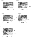
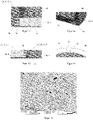
- a person skilled in the art can clearly identify a thermally sprayed layer on the basis of its microstructure. The spray particles deform when they hit the substrate, resulting in the "pancake structure" typical of thermally sprayed coatings.
- Thermal spraying processes include molten pool spraying, arc spraying, plasma spraying, flame spraying, high-velocity flame spraying, detonation spraying, cold gas spraying, laser spraying and PTWA (plasma transferred wire arc) spraying.
- plasma spraying and atmospheric plasma spraying plasma spraying under protective gas and vacuum plasma spraying.
- the thermally sprayed layer forms an excellent connection with the parts to be connected, which makes it possible to produce containers that fulfill the object of the invention. It is particularly surprising that these containers exhibit excellent tightness against melts, such as ceramic melts. Even in long-term use, the sprayed layer / part connection zone exhibits high resistance to the penetration of melts.
- the container according to the invention can have a variety of shapes (e.g. in terms of diameter (for round containers), length/width (for rectangular containers) and height, which cannot be realized with crucibles according to the prior art.
- the bonding zone of the sprayed layer/part is preferably designed as a material-locking and/or form-locking connection.
- connection partners are held together by atomic or molecular forces.
- the spray droplets have a temperature that is above the respective solidus temperature.
- the substrate is also usually heated.
- diffusion and/or a chemical reaction results in the formation of a material bond.
- a form-fitting connection is a connection that is created by the interlocking of at least two connection partners. For example, if the parts to be connected are rough, thermal spraying will fill the depressions with the spray material. This creates an interlocking effect and thus a form-fitting connection.
- connection is materially bonded or materially bonded and form-fitting.
- the sprayed layer is preferably designed as a seam.
- the seam is preferably formed from many injection layers.
- connection according to the invention is not to be assigned to the welded connections, the definition or description of the seam shape follows in accordance with the conventions in the field of welding technology. Instead of the welding filler material, the layer material forms the seam in the present invention.
- the description of the seam shapes can be found in standard textbooks, such as e.g Dubbel, paperback for mechanical engineering, 20th edition, Springer-Verlag, ISBN 3-540-67777-1, G10 be removed.
- the injection seam is preferably designed as a U, V, Y or I seam.
- a fillet weld is also a preferred embodiment.
- Particularly preferred seam shapes are the U and V seams.
- the opening angle of the V- or U-seam can be chosen within a wide range, whereby angles that reach beyond the usual range of weld seams can also be chosen.
- V includes the area of the parts to be connected. If the parts to be connected are thicker, a double V seam (X seam) or a double U seam can also be particularly advantageous. In the case of a parallel joint, fillet welds are suitable for securely connecting two or more parts.
- the parts to be connected are fixed or connected to one another by means of a form-fitting connection.
- the parts are designed, at least in certain areas, in such a way that a form-fitting connection is made possible.
- the tongue and groove and feather key connection as well as pinning should be mentioned as particularly advantageous form-fitting connections.
- Caulking achieves both a positive and a non-positive connection. Fixing or connecting the parts to be connected to one another by caulking represents a preferred embodiment of the invention.
- the refractory metal is advantageously molybdenum or tungsten.
- Advantageous molybdenum or tungsten alloys are Mo-W alloys in the entire concentration range as well as molybdenum or tungsten-based alloys with a molybdenum or tungsten content of> 80% by mass, advantageously> 90% by mass, particularly advantageously> 95 Ma %, the remainder being advantageously a refractory oxide.
- the oxide is advantageously present in a finely divided form in the base material.
- the sprayed layer is formed by plasma spraying.
- plasma spraying the coating material is melted by the high plasma temperature.
- the plasma stream entrains the particles and throws them onto the parts to be joined.
- the high temperature of the particles when they hit the parts to be connected ensures that a reliable material connection is formed between the sprayed layer and the parts to be connected.
- the parts to be connected are heated to a temperature >500°C, preferably >1000°C, particularly preferably >1500°C.
- the upper limit of the advantageous range is the melting point of the parts to be connected.
- Plasma spraying preferably takes place in a protective gas atmosphere (eg argon) or in a vacuum.
- the latter embodiment is a particularly advantageous embodiment of the invention, since a coating process in a vacuum ensures that no oxide layer or oxide areas can form in the area of the interface between the sprayed layer and the part, which would adversely affect both the connection strength and the grain boundary corrosion resistance affects / affect.
- Another preferred embodiment of the invention is when both the sprayed layer and the parts to be connected are formed from refractory metal or a refractory metal alloy. It is particularly advantageous if the sprayed layer and the parts to be connected are made of the same material or, in the case of an alloy, have at least the same base material.
- the container is advantageously designed as a round container, e.g. as a crucible.
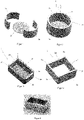
- the round container is advantageously formed by at least two parts, which are designed as hollow cylinder segments, and at least one base part.
- the container is preferably formed by at least two side parts and at least one U-shaped or plate-shaped bottom part.
- rectangular containers can only be manufactured by netshape pressing/sintering processes. In terms of forming, for example by deep drawing, it is not possible to produce larger rectangular containers.
- the present invention makes it possible, even rectangular containers with very to produce high density. Also with regard to the crucible dimensions there are no limits in a wide range. For example, very large-format crucibles can be produced.
- the high density of the container is preferably achieved in that the parts to be connected (e.g. hollow cylinder and base part) are made from deformed material.
- the parts to be connected e.g. hollow cylinder and base part
- the parts to be connected are made from deformed material.
- the bottom part can also be made from a rolled plate.
- the parts to be connected can be processed easily and inexpensively using conventional methods.
- the sprayed layer of the container is advantageously impervious to a ceramic melt (for example Al 2 O 3 ).
- a ceramic melt for example Al 2 O 3
- Material damage such as grain boundary contamination, pores at grain boundaries and grain boundary cracks can greatly reduce the tightness of a melting vessel. It is therefore very surprising for the person skilled in the art that a sprayed layer, which usually also has material defects, is impervious to an Al 2 O 3 melt even over very long periods of time.
- pores in the sprayed layer which are largely in isolated form, affect the tightness to a lesser extent.
- the sprayed layer can advantageously not only serve as a connecting element between the parts, but also, applied in a planar form, improve the tightness of the parts. This is particularly advantageous for parts that are only pressed / sintered.
- the sprayed layer can be applied in a simple manner before the connection process. It is thus possible in a simple manner to produce containers which are at least partially provided with a thermal spray coating on the inside and/or outside.
- the relative density (measured density based on theoretical density) of the sprayed layer in the region of the connection zone and/or the sprayed layer applied over the area is preferably >95%. Excellent results can be achieved when the relative density is >98%, particularly advantageously >99%.
- the object at hand is also solved by a method for producing a container.
- the container consists at least partially of refractory metal or a refractory metal alloy, with the refractory metal content being >80% by mass.
- the parts are advantageously produced by conventional powder metallurgy and/or metal forming processes.
- the parts can be produced by pressing, sintering and subsequent forming, for example rolling. Further forming steps advantageously include bending or embossing. Production by hot isostatic pressing (HIPing), optionally followed by a forming process, is also a preferred method.
- HIPing hot isostatic pressing
- the thermal spray coating is preferably applied by melt pool spraying, arc spraying, plasma spraying, flame spraying, high-velocity flame spraying, detonation spraying, cold gas spraying, laser spraying or PTWA (Plasma Transferred Wire Arc) spraying.
- PTWA Pullasma Transferred Wire Arc
- the material connection can only be weak (through micro-welding).
- the parts to be connected are mechanically processed prior to the application of the sprayed layer in such a way that they are fixed to one another or connected to one another at least in certain areas in a form-fitting, force-fitting and/or material-locking manner can become.
- Particularly advantageous connections are tongue and groove, pin, press and shrink connections.
- the parts are advantageously preferably machined mechanically in such a way that the parts can be connected by means of a thermally sprayed seam.
- Plasma spraying and here again vacuum plasma spraying, should be mentioned as a particularly advantageous thermal spraying process.
- the material for the sprayed layer is advantageously introduced radially as a powder into a plasma jet generated by a DC arc discharge, melted in the plasma jet and the melted droplets deposited on a base body. Since the process is carried out under negative pressure, oxidation of the coating material is avoided.
- a particularly advantageous process is inductive vacuum plasma spraying (IVPS).
- IVPS inductive vacuum plasma spraying
- a major difference to conventional plasma spraying is that the plasma is generated by inductive heating, which means that the spray powder can be easily introduced axially before the plasma jet is formed .
- the powder particles remain in the plasma jet for much longer. This improves the energy transfer from the plasma to the individual particles of the spray powder, so that even larger particles are heated completely above their melting point and can be deposited as fully melted droplets. It is thus possible to use cheaper spray powders with a broader particle size distribution without impairing the layer quality.
- the structure that occurs during inductive plasma spraying has an even further improved impermeability (relative density preferably > 98%) compared to very thin ceramic melts.
- the low relative speed with which the plasma jet sweeps over the surface to be coated also proves to be advantageous.
- the comparatively larger beam diameter also has a positive effect on the coating process.
- a further improvement in the material connection can be achieved if the parts to be connected are preheated with the plasma jet, for example to a temperature greater than 700° C. (for example 700 to 2000° C.).
- the bond zone can be sealed by exposure to a slurry, optionally followed by an anneal.
- the powder particles of the slurry advantageously also consist of a refractory metal or a refractory metal alloy, with the mean particle size (measured by means of laser diffraction) advantageously being ⁇ 1 ⁇ m.
- the inventive containers are suitable for melting aluminum oxide using conventional methods, such as the Kyropoulos, HEM, EFG, CHES, Bagdasarov or Czochralski process.
- the parts (2d, e, f) were connected in a cohesive manner using a thermally sprayed layer (3c), which was produced by IVPS.
- the clamped parts were mounted in a holder in a spray chamber suitable for vacuum.
- a commercially available Mo plasma spray powder was used for the spraying process.
- the IVPS spraying process was performed with parameters usual for refractory metals (see for example EP 0 874 385 A1 ) accomplished.
- the rectangular container (1) was removed from the vacuum chamber and the end faces were machined (milling, grinding). A photo of the rectangular container (1) is in figure 5 played back.
- the parts (2a,b,c) were then fixed positively and non-positively to each other by caulking in the area (5b) and connected to each other (see figures 9 and 14 ).
- the parts (2a,b,c) were materially connected via a thermally sprayed U-seam (3a) made of W, which was produced by IVPS.
- the clamped parts were mounted in a holder in a spray chamber suitable for vacuum.
- a commercially available W plasma spray powder was again used for the spraying process.
- the IVPS spraying process was performed with parameters usual for refractory metals (see for example EP 0 874 385 A1 ) accomplished.
- the round container (1) was removed from the vacuum chamber and the end faces were machined (milling, grinding).
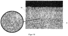
- the outside of the floor was also provided with a 300 ⁇ m thick W layer (4a). Subsequently, aluminum oxide according to Example 1 was melted in this round container (1). The metallographic examination showed no penetration of aluminum oxide in the area of the material connection. figure 16 shows that the W layer (4a) has fewer pores than the W sintered plate (2c).
- the positive and non-positive fixing of the parts (2d,e,f) was carried out by caulking (5c), the material connection via a thermally sprayed Mo layer (3a) with a U-seam shape, which was produced by IVPS.
- the layer (3a) was produced according to Example 1. After the spraying process, the rectangular container (1) was removed from the vacuum chamber and the end faces were machined (milling, grinding).
- the parts (2a,b,c) were then positively fixed to one another via the tongue and groove connection (5b).
- the parts (2a,b,c) were connected by a thermally sprayed Mo U seam (3a), which was produced by IVPS.
- the layer (3a) was produced according to Example 1. After the spraying process, the round container (1) was removed from the vacuum chamber and the end faces were machined (milling, grinding).
- a ring of Inconel 718 with the composition 0.04% by mass C; 19% by mass Cr; 3.0% by mass Mo; 52.5% by mass Ni; 0.9% by mass Al; ⁇ 0.1 Ma% Cu; 5.1% by mass Nb; 0.9% by mass of Ti and 19% by mass of Fe was bonded to a bottom plate (2c) made of Mo.
- the material connection was made using a sprayed V-seam (3b) (see figure 6 ) realized. Mo was used as the material for the sprayed seam.
- a round container (1) with a tight, materially bonded connection could also be produced with dissimilar materials (Ni-based superalloy and refractory metal).
- Mo plates which were made from a rolled plate with a thickness of 15 mm, different variants for form-fitting fixing and material-to-substance bonding were successfully tested. Sealing layers were also produced. In each case, Mo was used as the layer material (spraying conditions according to Example 1).
Landscapes
- Chemical & Material Sciences (AREA)
- Engineering & Computer Science (AREA)
- Mechanical Engineering (AREA)
- Materials Engineering (AREA)
- Metallurgy (AREA)
- Organic Chemistry (AREA)
- Chemical Kinetics & Catalysis (AREA)
- Physics & Mathematics (AREA)
- Plasma & Fusion (AREA)
- Manufacturing & Machinery (AREA)
- Crystallography & Structural Chemistry (AREA)
- Composite Materials (AREA)
- Inorganic Chemistry (AREA)
- Coating By Spraying Or Casting (AREA)
Claims (15)
- Contenant (1), qui comprend au moins deux parties (2a, 2b, 2c, 2d, 2e, 2f) reliées entre elles, lesquelles parties forment une partie de fond et une partie latérale ou un segment cylindrique creux du contenant (1), les parties (2a, 2b, 2c, 2d, 2e, 2f, 2f, 2c, 2d, 2e, 2f) étant constituées de métal réfractaire ou d'un alliage de métal réfractaire ayant une teneur en métal réfractaire > 80 % en masse,
les au moins deux parties (2a, 2b, 2c, 2d, 2e, 2f) étant reliées entre elles au moins par zones par l'intermédiaire d'une couche de pulvérisation thermique (3a, 3b, 3c) pour former le contenant (1). - Contenant (1) selon la revendication 1, caractérisé en ce que la couche de pulvérisation thermique (3) forme avec au moins une partie (2a, 2b, 2c, 2d, 2e, 2f) une liaison avec au moins un principe actif choisi dans le groupe de la liaison par la matière et de la liaison par la forme.
- Contenant (1) selon la revendication 1 ou 2, caractérisé en ce que la couche de pulvérisation thermique (3a, 3b, 3c) est réalisée sous la forme d'un joint (3a, 3b).
- Contenant (1) selon l'une quelconque des revendications précédentes, caractérisé en ce que les au moins deux parties (2a, 2b, 2c, 2d, 2e, 2f) sont réalisées au moins par zones de telle sorte que celles-ci sont fixées ou reliées entre elles par une liaison par la forme, par la force et/ou par la matière.
- Contenant (1) selon l'une quelconque des revendications précédentes, caractérisé en ce que le métal réfractaire est le molybdène ou le tungstène.
- Contenant (1) selon l'une quelconque des revendications précédentes, caractérisé en ce que la couche de pulvérisation thermique (3a, 3b, 3c) est formée par pulvérisation au plasma.
- Contenant (1) selon l'une quelconque des revendications précédentes, caractérisé en ce que la couche de pulvérisation thermique (3a, 3b, 3c) est formée à partir d'un métal réfractaire.
- Contenant (1) selon l'une quelconque des revendications précédentes, caractérisé en ce qu'une couche d'étanchéité (4a, 4b) est appliquée sur le côté intérieur et/ou extérieur du contenant.
- Contenant (1) selon l'une quelconque des revendications précédentes, caractérisé en ce que la couche de pulvérisation thermique (3a, 3b, 3c) et/ou la couche d'étanchéité (4a, 4b) sont étanches par rapport à une masse fondue de céramique.
- Procédé de fabrication d'un contenant (1), qui est constitué au moins par zones de métal réfractaire ou d'un alliage de métal réfractaire ayant une teneur en métal réfractaire > 80 % en masse,
caractérisé en ce que
celui-ci comprend au moins les étapes suivantes :- la fabrication d'au moins deux parties (2a, 2b, 2c, 2d, 2e, 2f) ;- l'application au moins par zones d'une couche de pulvérisation thermique (3a, 3b, 3c), de telle sorte que la couche de pulvérisation thermique (3a, 3b, 3c) relie au moins par zones les au moins deux parties (2a, 2b, 2c, 2d, 2e, 2f) par la matière ou par la forme. - Procédé selon la revendication 10 pour la fabrication d'un contenant (1) selon l'une quelconque des revendications 1 à 9.
- Procédé selon la revendication 10 ou 11, caractérisé en ce que la fabrication des parties (2a, 2b, 2c, 2d, 2e, 2f) comprend au moins une étape de fabrication du groupe du pressage de poudre, du frittage, du pressage isostatique à chaud et du formage.
- Procédé selon l'une quelconque des revendications 10 à 12, caractérisé en ce que les parties (2a, 2b, 2c, 2d, 2e, 2f) sont usinées mécaniquement de telle sorte que celles-ci peuvent être fixées ou reliées entre elles au moins par zones par liaison par la forme, la force et/ou la matière.
- Procédé selon l'une quelconque des revendications 10 à 13, caractérisé en ce que les parties (2a, 2b, 2c, 2d, 2e, 2f) sont reliées par un procédé de pulvérisation thermique choisi dans le groupe constitué par la pulvérisation au plasma, notamment la pulvérisation au plasma sous vide, la pulvérisation à l'arc électrique, la pulvérisation à la flamme, la pulvérisation par détonation, la pulvérisation au gaz froid et la pulvérisation au laser.
- Procédé selon l'une quelconque des revendications 10 à 14, caractérisé en ce que le contenant (1) est scellé sous l'action d'une pâte et éventuellement d'un recuit ultérieur.
Applications Claiming Priority (2)
| Application Number | Priority Date | Filing Date | Title |
|---|---|---|---|
| ATGM195/2015U AT14854U1 (de) | 2015-07-03 | 2015-07-03 | Behälter aus Refraktärmetall |
| PCT/AT2016/000066 WO2017004630A1 (fr) | 2015-07-03 | 2016-06-16 | Contenant en métal réfractaire |
Publications (2)
| Publication Number | Publication Date |
|---|---|
| EP3317036A1 EP3317036A1 (fr) | 2018-05-09 |
| EP3317036B1 true EP3317036B1 (fr) | 2022-05-18 |
Family
ID=56320684
Family Applications (1)
| Application Number | Title | Priority Date | Filing Date |
|---|---|---|---|
| EP16741842.5A Active EP3317036B1 (fr) | 2015-07-03 | 2016-06-16 | Contenant en métal réfractaire |
Country Status (8)
| Country | Link |
|---|---|
| US (1) | US10730111B2 (fr) |
| EP (1) | EP3317036B1 (fr) |
| JP (1) | JP6858140B2 (fr) |
| KR (1) | KR102461434B1 (fr) |
| CN (1) | CN107921537B (fr) |
| AT (1) | AT14854U1 (fr) |
| ES (1) | ES2925060T3 (fr) |
| WO (1) | WO2017004630A1 (fr) |
Families Citing this family (3)
| Publication number | Priority date | Publication date | Assignee | Title |
|---|---|---|---|---|
| JP7090511B2 (ja) * | 2017-09-29 | 2022-06-24 | Dowaエレクトロニクス株式会社 | 銀粉およびその製造方法 |
| CN109321865B (zh) * | 2018-12-06 | 2020-12-15 | 江苏丰东热技术有限公司 | 一种在钛合金表面形成MoSi2抗氧化涂层的方法 |
| CN112705692A (zh) * | 2020-12-22 | 2021-04-27 | 武志强 | 一种铸造模具 |
Family Cites Families (35)
| Publication number | Priority date | Publication date | Assignee | Title |
|---|---|---|---|---|
| US2205940A (en) * | 1939-05-02 | 1940-06-25 | M H Treadwell Co Inc | Ladle |
| US2294044A (en) * | 1940-03-09 | 1942-08-25 | Nat Tube Co | Ladle |
| US2472456A (en) * | 1945-03-20 | 1949-06-07 | Robert J Anicetti | Crucible and method of making crucibles |
| CH581515A5 (fr) * | 1975-01-23 | 1976-11-15 | Metacon Ag | |
| GB1593397A (en) * | 1976-10-12 | 1981-07-15 | Foseco Trading Ag | Slag pots |
| US4403955A (en) * | 1982-02-22 | 1983-09-13 | General Signal Corporation | Receptacle for support of a melt containing crucible |
| JPH01249666A (ja) | 1988-03-31 | 1989-10-04 | Nippon Steel Corp | 溶射によるセラミックの接合方法 |
| US5126102A (en) * | 1990-03-15 | 1992-06-30 | Kabushiki Kaisha Toshiba | Fabricating method of composite material |
| DE4025956A1 (de) | 1990-08-16 | 1992-02-20 | Didier Werke Ag | Feuerfeste fuellung eines ringspaltes bei einem metallurgischen gefaess |
| JPH0593254A (ja) | 1991-09-30 | 1993-04-16 | Sumitomo Metal Ind Ltd | 金属接合方法 |
| DE4201748C2 (de) | 1992-01-23 | 1994-01-05 | Intocast Gmbh | Verfahren zur Herstellung der feuerfesten Zustellung einer Gießpfanne |
| US5482257A (en) * | 1992-09-25 | 1996-01-09 | Martin Marietta Energy Systems, Inc. | Non-graphite crucible for high temperature applications |
| US5332200A (en) * | 1992-10-13 | 1994-07-26 | Martin Marietta Energy Systems, Inc. | Segmented ceramic liner for induction furnaces |
| AT1984U1 (de) | 1997-04-22 | 1998-02-25 | Plansee Ag | Verfahren zur herstellung einer anode für röntgenröhren |
| US5988488A (en) * | 1997-09-02 | 1999-11-23 | Mcdonnell Douglas Corporation | Process of bonding copper and tungsten |
| JPH11254152A (ja) | 1998-03-06 | 1999-09-21 | Toshiba Corp | 導体の溶接方法 |
| US6399017B1 (en) * | 2000-06-01 | 2002-06-04 | Aemp Corporation | Method and apparatus for containing and ejecting a thixotropic metal slurry |
| DE102005018021B4 (de) * | 2005-04-18 | 2007-05-03 | esb Schweißbetrieb Burbach & Bender GmbH & Co. KG | Ausziehvorrichtung für einen Gasspülstein |
| CN100582626C (zh) * | 2005-06-09 | 2010-01-20 | 日本坩埚株式会社 | 坩埚式连续熔解炉 |
| JP5252157B2 (ja) * | 2008-02-05 | 2013-07-31 | 株式会社Sumco | 石英ガラスルツボ |
| JP2010024123A (ja) * | 2008-07-24 | 2010-02-04 | Sumco Corp | シリコン融液の供給装置およびこれを備えたシリコン単結晶の育成装置 |
| CH699948A2 (de) | 2008-11-17 | 2010-05-31 | Stopinc Ag | Behälter für Metallschmelze sowie ein Verfahren zur auswechselbaren Befestigung eines feuerfesten Spülsteins oder einer feuerfesten Hülse. |
| DE102008060520A1 (de) * | 2008-12-04 | 2010-06-10 | Schott Ag | Ein Tiegel zur Prozessierung hochschmelzender Materialien |
| DE102008061871B4 (de) * | 2008-12-15 | 2012-10-31 | Heraeus Quarzglas Gmbh & Co. Kg | Schmelztiegel für den Einsatz in einem Tiegelziehverfahren für Quarzglas |
| DE102009033501B4 (de) * | 2009-07-15 | 2016-07-21 | Schott Ag | Verfahren und Vorrichtung zum kontinuierlichen Schmelzen oder Läutern von Schmelzen |
| AT12783U1 (de) | 2011-08-05 | 2012-11-15 | Plansee Se | Tiegel zur kristallzucht |
| US20130192302A1 (en) * | 2012-02-01 | 2013-08-01 | Memc Singapore Pte. Ltd. (Uen200614794D) | Crucibles for holding molten material and methods for producing them and for their use |
| CN202530198U (zh) | 2012-02-28 | 2012-11-14 | 浙江上城科技有限公司 | 一种复合式耐高温坩埚 |
| US20150128849A1 (en) * | 2012-04-17 | 2015-05-14 | Plansee Se | Crucible for the manufacture of oxide ceramic single crystals |
| CN103374755A (zh) * | 2012-04-28 | 2013-10-30 | 洛阳高科钼钨材料有限公司 | 非整体式坩埚 |
| TWI532890B (zh) * | 2012-06-25 | 2016-05-11 | 希利柯爾材料股份有限公司 | 矽之控制定向固化 |
| KR101697027B1 (ko) * | 2012-06-25 | 2017-01-16 | 실리코르 머티리얼즈 인코포레이티드 | 실리콘 용융물의 정제용 내화 도가니의 표면용 라이닝 및 용융 및 추가적인 방향성 고체화를 위하여 상기 도가니(들)를 이용하는 실리콘 용융물의 정제 방법 |
| CN104755868B (zh) * | 2012-08-01 | 2018-06-05 | 联合矿产(天津)有限公司 | 加强的耐火容器 |
| CN104685114B (zh) * | 2012-09-28 | 2017-07-28 | 联合材料公司 | 蓝宝石单晶生长用坩锅和蓝宝石单晶生长用坩锅的制造方法 |
| CN102989856B (zh) * | 2012-12-03 | 2014-12-10 | 西安超晶新能源材料有限公司 | 一种大型变壁厚纯钼坩埚的成型方法 |
-
2015
- 2015-07-03 AT ATGM195/2015U patent/AT14854U1/de not_active IP Right Cessation
-
2016
- 2016-06-16 JP JP2017567801A patent/JP6858140B2/ja active Active
- 2016-06-16 ES ES16741842T patent/ES2925060T3/es active Active
- 2016-06-16 CN CN201680039442.4A patent/CN107921537B/zh active Active
- 2016-06-16 KR KR1020177037391A patent/KR102461434B1/ko active IP Right Grant
- 2016-06-16 US US15/741,620 patent/US10730111B2/en active Active
- 2016-06-16 EP EP16741842.5A patent/EP3317036B1/fr active Active
- 2016-06-16 WO PCT/AT2016/000066 patent/WO2017004630A1/fr active Application Filing
Also Published As
| Publication number | Publication date |
|---|---|
| US20190255619A1 (en) | 2019-08-22 |
| US10730111B2 (en) | 2020-08-04 |
| EP3317036A1 (fr) | 2018-05-09 |
| KR20180026398A (ko) | 2018-03-12 |
| WO2017004630A1 (fr) | 2017-01-12 |
| JP2018528321A (ja) | 2018-09-27 |
| CN107921537B (zh) | 2020-10-13 |
| JP6858140B2 (ja) | 2021-04-14 |
| ES2925060T3 (es) | 2022-10-13 |
| KR102461434B1 (ko) | 2022-10-31 |
| AT14854U1 (de) | 2016-07-15 |
| CN107921537A (zh) | 2018-04-17 |
Similar Documents
| Publication | Publication Date | Title |
|---|---|---|
| EP3691815B1 (fr) | Composant produit par fabrication additive et procédé de production de ce composant | |
| EP3084517B1 (fr) | Cible w-ni de pulvérisation cathodique | |
| EP2531627B1 (fr) | Systèmes et procédés de formage et de traitement de lingots d'alliage | |
| EP1678733B1 (fr) | Procede de production d'un corps composite par soudage a haute temperature d'un composant non metallique a un composant metallique ou non metallique | |
| EP3317036B1 (fr) | Contenant en métal réfractaire | |
| US6223976B1 (en) | Process for the assembly or refacing of titanium aluminide articles by diffusion brazing | |
| EP3994287A1 (fr) | Alliage à base de nickel pour poudre et procédé de fabrication d'une poudre | |
| JP7018603B2 (ja) | クラッド層の製造方法 | |
| EP3590634A2 (fr) | Passivation de surface du poudre contenant de l'aluminium | |
| EP3732310B1 (fr) | Alliage d'aluminium | |
| EP2276711B1 (fr) | Procédé de fabrication d'objets céramiques par fusion laser sélective | |
| AT517894B1 (de) | Rührreibschweißwerkzeug | |
| EP3883708A1 (fr) | Élément en métal réfractaire fabriqué de manière additive, procédé de fabrication additive et poudre | |
| EP0677355B1 (fr) | Matériau pour brasage | |
| DE102007016411B4 (de) | Halbzeug aus Molybdän, welches mit einer Schutzschicht versehen ist, und Verfahren zu dessen Herstellung | |
| EP3883711A1 (fr) | Composant métallique réfractaire produit par fabrication additive, procédé de fabrication additive et poudre | |
| EP3411516B1 (fr) | Creuset | |
| EP2343143A2 (fr) | Procédé de fabrication de composants en métaux réfractaires | |
| Akram et al. | Microstructural studies on friction surfaced coatings of Ni-based alloys | |
| WO2014134643A1 (fr) | Assemblage soudé de métaux réfractaires | |
| DE102017009948A1 (de) | Verfahren zur Reparatur einkristalliner Werkstoffe | |
| Fischer | Physico-chemistry of zirconia to titanium brazing using pure gold: wetting and interfacial reactivity | |
| AT17662U1 (de) | Bauteil aus Refraktärmetall |
Legal Events
| Date | Code | Title | Description |
|---|---|---|---|
| STAA | Information on the status of an ep patent application or granted ep patent |
Free format text: STATUS: THE INTERNATIONAL PUBLICATION HAS BEEN MADE |
|
| PUAI | Public reference made under article 153(3) epc to a published international application that has entered the european phase |
Free format text: ORIGINAL CODE: 0009012 |
|
| STAA | Information on the status of an ep patent application or granted ep patent |
Free format text: STATUS: REQUEST FOR EXAMINATION WAS MADE |
|
| 17P | Request for examination filed |
Effective date: 20171219 |
|
| AK | Designated contracting states |
Kind code of ref document: A1 Designated state(s): AL AT BE BG CH CY CZ DE DK EE ES FI FR GB GR HR HU IE IS IT LI LT LU LV MC MK MT NL NO PL PT RO RS SE SI SK SM TR |
|
| AX | Request for extension of the european patent |
Extension state: BA ME |
|
| DAV | Request for validation of the european patent (deleted) | ||
| DAX | Request for extension of the european patent (deleted) | ||
| STAA | Information on the status of an ep patent application or granted ep patent |
Free format text: STATUS: EXAMINATION IS IN PROGRESS |
|
| 17Q | First examination report despatched |
Effective date: 20200330 |
|
| STAA | Information on the status of an ep patent application or granted ep patent |
Free format text: STATUS: EXAMINATION IS IN PROGRESS |
|
| GRAP | Despatch of communication of intention to grant a patent |
Free format text: ORIGINAL CODE: EPIDOSNIGR1 |
|
| STAA | Information on the status of an ep patent application or granted ep patent |
Free format text: STATUS: GRANT OF PATENT IS INTENDED |
|
| RIC1 | Information provided on ipc code assigned before grant |
Ipc: B22F 3/15 20060101ALN20211206BHEP Ipc: B22F 3/10 20060101ALN20211206BHEP Ipc: B22F 3/02 20060101ALN20211206BHEP Ipc: C30B 35/00 20060101ALI20211206BHEP Ipc: C30B 29/20 20060101ALI20211206BHEP Ipc: C23C 24/04 20060101ALI20211206BHEP Ipc: C23C 4/18 20060101ALI20211206BHEP Ipc: C23C 4/08 20160101ALI20211206BHEP Ipc: C23C 4/02 20060101ALI20211206BHEP Ipc: B22D 41/00 20060101ALI20211206BHEP Ipc: B22F 7/06 20060101ALI20211206BHEP Ipc: B22F 5/00 20060101AFI20211206BHEP |
|
| INTG | Intention to grant announced |
Effective date: 20211223 |
|
| RIC1 | Information provided on ipc code assigned before grant |
Ipc: B22F 3/15 20060101ALN20211210BHEP Ipc: B22F 3/10 20060101ALN20211210BHEP Ipc: B22F 3/02 20060101ALN20211210BHEP Ipc: C30B 35/00 20060101ALI20211210BHEP Ipc: C30B 29/20 20060101ALI20211210BHEP Ipc: C23C 24/04 20060101ALI20211210BHEP Ipc: C23C 4/18 20060101ALI20211210BHEP Ipc: C23C 4/08 20160101ALI20211210BHEP Ipc: C23C 4/02 20060101ALI20211210BHEP Ipc: B22D 41/00 20060101ALI20211210BHEP Ipc: B22F 7/06 20060101ALI20211210BHEP Ipc: B22F 5/00 20060101AFI20211210BHEP |
|
| GRAS | Grant fee paid |
Free format text: ORIGINAL CODE: EPIDOSNIGR3 |
|
| GRAA | (expected) grant |
Free format text: ORIGINAL CODE: 0009210 |
|
| STAA | Information on the status of an ep patent application or granted ep patent |
Free format text: STATUS: THE PATENT HAS BEEN GRANTED |
|
| AK | Designated contracting states |
Kind code of ref document: B1 Designated state(s): AL AT BE BG CH CY CZ DE DK EE ES FI FR GB GR HR HU IE IS IT LI LT LU LV MC MK MT NL NO PL PT RO RS SE SI SK SM TR |
|
| REG | Reference to a national code |
Ref country code: GB Ref legal event code: FG4D Free format text: NOT ENGLISH |
|
| REG | Reference to a national code |
Ref country code: CH Ref legal event code: EP |
|
| REG | Reference to a national code |
Ref country code: IE Ref legal event code: FG4D Free format text: LANGUAGE OF EP DOCUMENT: GERMAN |
|
| REG | Reference to a national code |
Ref country code: DE Ref legal event code: R096 Ref document number: 502016014905 Country of ref document: DE |
|
| REG | Reference to a national code |
Ref country code: AT Ref legal event code: REF Ref document number: 1492859 Country of ref document: AT Kind code of ref document: T Effective date: 20220615 |
|
| REG | Reference to a national code |
Ref country code: LT Ref legal event code: MG9D |
|
| REG | Reference to a national code |
Ref country code: NL Ref legal event code: MP Effective date: 20220518 |
|
| REG | Reference to a national code |
Ref country code: ES Ref legal event code: FG2A Ref document number: 2925060 Country of ref document: ES Kind code of ref document: T3 Effective date: 20221013 |
|
| PG25 | Lapsed in a contracting state [announced via postgrant information from national office to epo] |
Ref country code: SE Free format text: LAPSE BECAUSE OF FAILURE TO SUBMIT A TRANSLATION OF THE DESCRIPTION OR TO PAY THE FEE WITHIN THE PRESCRIBED TIME-LIMIT Effective date: 20220518 Ref country code: PT Free format text: LAPSE BECAUSE OF FAILURE TO SUBMIT A TRANSLATION OF THE DESCRIPTION OR TO PAY THE FEE WITHIN THE PRESCRIBED TIME-LIMIT Effective date: 20220919 Ref country code: NO Free format text: LAPSE BECAUSE OF FAILURE TO SUBMIT A TRANSLATION OF THE DESCRIPTION OR TO PAY THE FEE WITHIN THE PRESCRIBED TIME-LIMIT Effective date: 20220818 Ref country code: NL Free format text: LAPSE BECAUSE OF FAILURE TO SUBMIT A TRANSLATION OF THE DESCRIPTION OR TO PAY THE FEE WITHIN THE PRESCRIBED TIME-LIMIT Effective date: 20220518 Ref country code: LT Free format text: LAPSE BECAUSE OF FAILURE TO SUBMIT A TRANSLATION OF THE DESCRIPTION OR TO PAY THE FEE WITHIN THE PRESCRIBED TIME-LIMIT Effective date: 20220518 Ref country code: HR Free format text: LAPSE BECAUSE OF FAILURE TO SUBMIT A TRANSLATION OF THE DESCRIPTION OR TO PAY THE FEE WITHIN THE PRESCRIBED TIME-LIMIT Effective date: 20220518 Ref country code: GR Free format text: LAPSE BECAUSE OF FAILURE TO SUBMIT A TRANSLATION OF THE DESCRIPTION OR TO PAY THE FEE WITHIN THE PRESCRIBED TIME-LIMIT Effective date: 20220819 Ref country code: FI Free format text: LAPSE BECAUSE OF FAILURE TO SUBMIT A TRANSLATION OF THE DESCRIPTION OR TO PAY THE FEE WITHIN THE PRESCRIBED TIME-LIMIT Effective date: 20220518 Ref country code: BG Free format text: LAPSE BECAUSE OF FAILURE TO SUBMIT A TRANSLATION OF THE DESCRIPTION OR TO PAY THE FEE WITHIN THE PRESCRIBED TIME-LIMIT Effective date: 20220818 |
|
| PG25 | Lapsed in a contracting state [announced via postgrant information from national office to epo] |
Ref country code: RS Free format text: LAPSE BECAUSE OF FAILURE TO SUBMIT A TRANSLATION OF THE DESCRIPTION OR TO PAY THE FEE WITHIN THE PRESCRIBED TIME-LIMIT Effective date: 20220518 Ref country code: PL Free format text: LAPSE BECAUSE OF FAILURE TO SUBMIT A TRANSLATION OF THE DESCRIPTION OR TO PAY THE FEE WITHIN THE PRESCRIBED TIME-LIMIT Effective date: 20220518 Ref country code: LV Free format text: LAPSE BECAUSE OF FAILURE TO SUBMIT A TRANSLATION OF THE DESCRIPTION OR TO PAY THE FEE WITHIN THE PRESCRIBED TIME-LIMIT Effective date: 20220518 Ref country code: IS Free format text: LAPSE BECAUSE OF FAILURE TO SUBMIT A TRANSLATION OF THE DESCRIPTION OR TO PAY THE FEE WITHIN THE PRESCRIBED TIME-LIMIT Effective date: 20220918 |
|
| PG25 | Lapsed in a contracting state [announced via postgrant information from national office to epo] |
Ref country code: SM Free format text: LAPSE BECAUSE OF FAILURE TO SUBMIT A TRANSLATION OF THE DESCRIPTION OR TO PAY THE FEE WITHIN THE PRESCRIBED TIME-LIMIT Effective date: 20220518 Ref country code: SK Free format text: LAPSE BECAUSE OF FAILURE TO SUBMIT A TRANSLATION OF THE DESCRIPTION OR TO PAY THE FEE WITHIN THE PRESCRIBED TIME-LIMIT Effective date: 20220518 Ref country code: RO Free format text: LAPSE BECAUSE OF FAILURE TO SUBMIT A TRANSLATION OF THE DESCRIPTION OR TO PAY THE FEE WITHIN THE PRESCRIBED TIME-LIMIT Effective date: 20220518 Ref country code: EE Free format text: LAPSE BECAUSE OF FAILURE TO SUBMIT A TRANSLATION OF THE DESCRIPTION OR TO PAY THE FEE WITHIN THE PRESCRIBED TIME-LIMIT Effective date: 20220518 Ref country code: DK Free format text: LAPSE BECAUSE OF FAILURE TO SUBMIT A TRANSLATION OF THE DESCRIPTION OR TO PAY THE FEE WITHIN THE PRESCRIBED TIME-LIMIT Effective date: 20220518 |
|
| REG | Reference to a national code |
Ref country code: BE Ref legal event code: MM Effective date: 20220630 |
|
| REG | Reference to a national code |
Ref country code: DE Ref legal event code: R097 Ref document number: 502016014905 Country of ref document: DE |
|
| PG25 | Lapsed in a contracting state [announced via postgrant information from national office to epo] |
Ref country code: MC Free format text: LAPSE BECAUSE OF FAILURE TO SUBMIT A TRANSLATION OF THE DESCRIPTION OR TO PAY THE FEE WITHIN THE PRESCRIBED TIME-LIMIT Effective date: 20220518 |
|
| PLBE | No opposition filed within time limit |
Free format text: ORIGINAL CODE: 0009261 |
|
| STAA | Information on the status of an ep patent application or granted ep patent |
Free format text: STATUS: NO OPPOSITION FILED WITHIN TIME LIMIT |
|
| PG25 | Lapsed in a contracting state [announced via postgrant information from national office to epo] |
Ref country code: AL Free format text: LAPSE BECAUSE OF FAILURE TO SUBMIT A TRANSLATION OF THE DESCRIPTION OR TO PAY THE FEE WITHIN THE PRESCRIBED TIME-LIMIT Effective date: 20220518 |
|
| 26N | No opposition filed |
Effective date: 20230221 |
|
| GBPC | Gb: european patent ceased through non-payment of renewal fee |
Effective date: 20220818 |
|
| PG25 | Lapsed in a contracting state [announced via postgrant information from national office to epo] |
Ref country code: LU Free format text: LAPSE BECAUSE OF NON-PAYMENT OF DUE FEES Effective date: 20220616 Ref country code: IE Free format text: LAPSE BECAUSE OF NON-PAYMENT OF DUE FEES Effective date: 20220616 |
|
| PG25 | Lapsed in a contracting state [announced via postgrant information from national office to epo] |
Ref country code: SI Free format text: LAPSE BECAUSE OF FAILURE TO SUBMIT A TRANSLATION OF THE DESCRIPTION OR TO PAY THE FEE WITHIN THE PRESCRIBED TIME-LIMIT Effective date: 20220518 Ref country code: BE Free format text: LAPSE BECAUSE OF NON-PAYMENT OF DUE FEES Effective date: 20220630 |
|
| PGFP | Annual fee paid to national office [announced via postgrant information from national office to epo] |
Ref country code: IT Payment date: 20220627 Year of fee payment: 8 Ref country code: FR Payment date: 20230630 Year of fee payment: 8 Ref country code: DE Payment date: 20230620 Year of fee payment: 8 Ref country code: CZ Payment date: 20230612 Year of fee payment: 8 |
|
| PGFP | Annual fee paid to national office [announced via postgrant information from national office to epo] |
Ref country code: AT Payment date: 20230621 Year of fee payment: 8 |
|
| PG25 | Lapsed in a contracting state [announced via postgrant information from national office to epo] |
Ref country code: GB Free format text: LAPSE BECAUSE OF NON-PAYMENT OF DUE FEES Effective date: 20220818 |
|
| PGFP | Annual fee paid to national office [announced via postgrant information from national office to epo] |
Ref country code: ES Payment date: 20230830 Year of fee payment: 8 Ref country code: CH Payment date: 20230702 Year of fee payment: 8 |
|
| PG25 | Lapsed in a contracting state [announced via postgrant information from national office to epo] |
Ref country code: HU Free format text: LAPSE BECAUSE OF FAILURE TO SUBMIT A TRANSLATION OF THE DESCRIPTION OR TO PAY THE FEE WITHIN THE PRESCRIBED TIME-LIMIT; INVALID AB INITIO Effective date: 20160616 |
|
| PG25 | Lapsed in a contracting state [announced via postgrant information from national office to epo] |
Ref country code: MK Free format text: LAPSE BECAUSE OF FAILURE TO SUBMIT A TRANSLATION OF THE DESCRIPTION OR TO PAY THE FEE WITHIN THE PRESCRIBED TIME-LIMIT Effective date: 20220511 Ref country code: CY Free format text: LAPSE BECAUSE OF FAILURE TO SUBMIT A TRANSLATION OF THE DESCRIPTION OR TO PAY THE FEE WITHIN THE PRESCRIBED TIME-LIMIT Effective date: 20220511 |