EP3316378A1 - Électrode négative comprenant du graphite partiellement orienté sur collecteur de courant pour batterie rechargeable au lithium, et batterie rechargeable au lithium - Google Patents
Électrode négative comprenant du graphite partiellement orienté sur collecteur de courant pour batterie rechargeable au lithium, et batterie rechargeable au lithium Download PDFInfo
- Publication number
- EP3316378A1 EP3316378A1 EP17199464.3A EP17199464A EP3316378A1 EP 3316378 A1 EP3316378 A1 EP 3316378A1 EP 17199464 A EP17199464 A EP 17199464A EP 3316378 A1 EP3316378 A1 EP 3316378A1
- Authority
- EP
- European Patent Office
- Prior art keywords
- negative electrode
- rechargeable lithium
- lithium battery
- active material
- negative
- Prior art date
- Legal status (The legal status is an assumption and is not a legal conclusion. Google has not performed a legal analysis and makes no representation as to the accuracy of the status listed.)
- Pending
Links
Images


Classifications
-
- H—ELECTRICITY
- H01—ELECTRIC ELEMENTS
- H01M—PROCESSES OR MEANS, e.g. BATTERIES, FOR THE DIRECT CONVERSION OF CHEMICAL ENERGY INTO ELECTRICAL ENERGY
- H01M4/00—Electrodes
- H01M4/02—Electrodes composed of, or comprising, active material
- H01M4/13—Electrodes for accumulators with non-aqueous electrolyte, e.g. for lithium-accumulators; Processes of manufacture thereof
- H01M4/133—Electrodes based on carbonaceous material, e.g. graphite-intercalation compounds or CFx
-
- H—ELECTRICITY
- H01—ELECTRIC ELEMENTS
- H01M—PROCESSES OR MEANS, e.g. BATTERIES, FOR THE DIRECT CONVERSION OF CHEMICAL ENERGY INTO ELECTRICAL ENERGY
- H01M10/00—Secondary cells; Manufacture thereof
- H01M10/05—Accumulators with non-aqueous electrolyte
- H01M10/052—Li-accumulators
- H01M10/0525—Rocking-chair batteries, i.e. batteries with lithium insertion or intercalation in both electrodes; Lithium-ion batteries
-
- H—ELECTRICITY
- H01—ELECTRIC ELEMENTS
- H01M—PROCESSES OR MEANS, e.g. BATTERIES, FOR THE DIRECT CONVERSION OF CHEMICAL ENERGY INTO ELECTRICAL ENERGY
- H01M4/00—Electrodes
- H01M4/02—Electrodes composed of, or comprising, active material
- H01M4/13—Electrodes for accumulators with non-aqueous electrolyte, e.g. for lithium-accumulators; Processes of manufacture thereof
- H01M4/131—Electrodes based on mixed oxides or hydroxides, or on mixtures of oxides or hydroxides, e.g. LiCoOx
-
- H—ELECTRICITY
- H01—ELECTRIC ELEMENTS
- H01M—PROCESSES OR MEANS, e.g. BATTERIES, FOR THE DIRECT CONVERSION OF CHEMICAL ENERGY INTO ELECTRICAL ENERGY
- H01M4/00—Electrodes
- H01M4/02—Electrodes composed of, or comprising, active material
- H01M4/13—Electrodes for accumulators with non-aqueous electrolyte, e.g. for lithium-accumulators; Processes of manufacture thereof
- H01M4/139—Processes of manufacture
- H01M4/1393—Processes of manufacture of electrodes based on carbonaceous material, e.g. graphite-intercalation compounds or CFx
-
- H—ELECTRICITY
- H01—ELECTRIC ELEMENTS
- H01M—PROCESSES OR MEANS, e.g. BATTERIES, FOR THE DIRECT CONVERSION OF CHEMICAL ENERGY INTO ELECTRICAL ENERGY
- H01M4/00—Electrodes
- H01M4/02—Electrodes composed of, or comprising, active material
- H01M4/36—Selection of substances as active materials, active masses, active liquids
- H01M4/48—Selection of substances as active materials, active masses, active liquids of inorganic oxides or hydroxides
- H01M4/485—Selection of substances as active materials, active masses, active liquids of inorganic oxides or hydroxides of mixed oxides or hydroxides for inserting or intercalating light metals, e.g. LiTi2O4 or LiTi2OxFy
-
- H—ELECTRICITY
- H01—ELECTRIC ELEMENTS
- H01M—PROCESSES OR MEANS, e.g. BATTERIES, FOR THE DIRECT CONVERSION OF CHEMICAL ENERGY INTO ELECTRICAL ENERGY
- H01M4/00—Electrodes
- H01M4/02—Electrodes composed of, or comprising, active material
- H01M4/36—Selection of substances as active materials, active masses, active liquids
- H01M4/58—Selection of substances as active materials, active masses, active liquids of inorganic compounds other than oxides or hydroxides, e.g. sulfides, selenides, tellurides, halogenides or LiCoFy; of polyanionic structures, e.g. phosphates, silicates or borates
- H01M4/583—Carbonaceous material, e.g. graphite-intercalation compounds or CFx
- H01M4/587—Carbonaceous material, e.g. graphite-intercalation compounds or CFx for inserting or intercalating light metals
-
- H—ELECTRICITY
- H01—ELECTRIC ELEMENTS
- H01M—PROCESSES OR MEANS, e.g. BATTERIES, FOR THE DIRECT CONVERSION OF CHEMICAL ENERGY INTO ELECTRICAL ENERGY
- H01M4/00—Electrodes
- H01M4/02—Electrodes composed of, or comprising, active material
- H01M2004/021—Physical characteristics, e.g. porosity, surface area
-
- H—ELECTRICITY
- H01—ELECTRIC ELEMENTS
- H01M—PROCESSES OR MEANS, e.g. BATTERIES, FOR THE DIRECT CONVERSION OF CHEMICAL ENERGY INTO ELECTRICAL ENERGY
- H01M4/00—Electrodes
- H01M4/02—Electrodes composed of, or comprising, active material
- H01M4/36—Selection of substances as active materials, active masses, active liquids
- H01M4/38—Selection of substances as active materials, active masses, active liquids of elements or alloys
- H01M4/386—Silicon or alloys based on silicon
-
- H—ELECTRICITY
- H01—ELECTRIC ELEMENTS
- H01M—PROCESSES OR MEANS, e.g. BATTERIES, FOR THE DIRECT CONVERSION OF CHEMICAL ENERGY INTO ELECTRICAL ENERGY
- H01M4/00—Electrodes
- H01M4/02—Electrodes composed of, or comprising, active material
- H01M4/36—Selection of substances as active materials, active masses, active liquids
- H01M4/38—Selection of substances as active materials, active masses, active liquids of elements or alloys
- H01M4/387—Tin or alloys based on tin
-
- H—ELECTRICITY
- H01—ELECTRIC ELEMENTS
- H01M—PROCESSES OR MEANS, e.g. BATTERIES, FOR THE DIRECT CONVERSION OF CHEMICAL ENERGY INTO ELECTRICAL ENERGY
- H01M4/00—Electrodes
- H01M4/02—Electrodes composed of, or comprising, active material
- H01M4/36—Selection of substances as active materials, active masses, active liquids
- H01M4/48—Selection of substances as active materials, active masses, active liquids of inorganic oxides or hydroxides
-
- Y—GENERAL TAGGING OF NEW TECHNOLOGICAL DEVELOPMENTS; GENERAL TAGGING OF CROSS-SECTIONAL TECHNOLOGIES SPANNING OVER SEVERAL SECTIONS OF THE IPC; TECHNICAL SUBJECTS COVERED BY FORMER USPC CROSS-REFERENCE ART COLLECTIONS [XRACs] AND DIGESTS
- Y02—TECHNOLOGIES OR APPLICATIONS FOR MITIGATION OR ADAPTATION AGAINST CLIMATE CHANGE
- Y02E—REDUCTION OF GREENHOUSE GAS [GHG] EMISSIONS, RELATED TO ENERGY GENERATION, TRANSMISSION OR DISTRIBUTION
- Y02E60/00—Enabling technologies; Technologies with a potential or indirect contribution to GHG emissions mitigation
- Y02E60/10—Energy storage using batteries
Definitions
- a negative electrode for a rechargeable lithium battery and a rechargeable lithium battery including the same are disclosed.
- a rechargeable lithium battery has recently drawn attention as a power source for small portable electronic devices.
- the rechargeable lithium battery uses an organic electrolyte solution and thereby, have twice or more as high a discharge voltage than a conventional battery using an alkali aqueous solution and accordingly, high energy density.
- a lithium-transition metal oxide having a structure capable of intercalating lithium ions such as LiCoO 2 , LiMn 2 O 4 , LiNi 1-x Co x O 2 (0 ⁇ x ⁇ 1), and the like has been used.
- negative active materials various carbon-based materials such as artificial graphite, natural graphite, hard carbon, and the like have been used. Recently, a non-carbon-based negative active material such as silicon or tin has been researched in order to obtain high capacity.
- An embodiment provides a negative electrode for a rechargeable lithium battery having improved electrochemical characteristics.
- Another embodiment provides a rechargeable lithium battery including the negative electrode.
- I a is a sum of peak intensities at non-planar angles measured by XRD using a CuK ⁇ ray
- I total is a sum of peak intensities at all angles measured by XRD using a CuK ⁇ ray.
- a BET specific surface area of the negative electrode may be less than about 5.0 m 2 /g.
- the DD value of the negative electrode may be greater than or equal to about 19 and less than or equal to about 60.
- the negative electrode may have a loading level (L/L) of about 6 mg/cm 2 to about 65 mg/cm 2 on one side of the current collector.
- the peak intensities may be a peak integral area value.
- the negative electrode may have a ratio(I (004) /I (002) ) of a peak intensity at a (004) plane relative to a peak intensity at a (002) plane of greater than or equal to about 0.04, for example greater than or equal to about 0.04 and less than or equal to about 0.07, measured by XRD using a CuK ⁇ ray.
- the carbon-based negative active material may be artificial graphite or a mixture of artificial graphite and natural graphite.
- the negative active material layer may further include a Si-based negative active material, a Sn-based negative active material, a lithium vanadium oxide, or a combination thereof.
- the negative electrode may have an active region facing a positive electrode and an inactive region not facing a positive electrode, and a DD value of the inactive region may be greater than or equal to about 19.
- Another embodiment provides a rechargeable lithium battery including the negative electrode; a positive electrode including a positive active material; and an electrolyte.
- the rechargeable lithium battery may be a high power battery.
- the rechargeable lithium battery may be a cylindrical battery.
- the rechargeable lithium battery may be a pouch type battery.
- the rechargeable lithium battery may be an 18650 type cylindrical battery or a 21700 type cylindrical battery.
- a negative electrode for a rechargeable lithium battery according to an embodiment may provide a rechargeable lithium battery having improved battery characteristics.
- I a is a sum of peak intensities at non-planar angles measured by XRD using a CuK ⁇ ray
- I total is a sum of peak intensities at all angles measured by XRD using a CuK ⁇ ray.
- graphite has a structure classified into a rhombohedral structure and a hexagonal structure having an ABAB type stacking sequence according to stacking order graphene layers, and the R plane denotes the rhombohedral structure, while the H plane denotes the hexagonal structure.
- peak intensity indicates a height of a peak or an integral area of the peak, and according to an embodiment, the peak intensity indicates the integral area of a peak.
- the DD value of the negative electrode may be greater than or equal to about 19 and less than or equal to about 60.
- the DD value of the negative electrode satisfying the condition means that a negative active material included in a negative active material layer is oriented at a predetermined angle, and this DD value is maintained after charges and discharges.
- a magnetic field may be applied, while a negative active material composition is coated on a current collector.
- a negative electrode having a DD value of greater than or equal to about 19 and specifically, greater than or equal to about 19 and less than or equal to about 60 according to an embodiment, strength of a magnetic field, exposure time to the magnetic field, and viscosity of a negative active material composition should be adjusted.
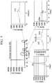
- the negative electrode is manufactured by disposing a current collector on or beneath a magnet and coating a negative active material composition including a negative active material on a current collector as shown in FIG. 1 .
- the magnet has strength of a magnetic field in a range of 1,000 Gauss to 10,000 Gauss (e.g . in a range of 1,000 Gauss to 5,000 Gauss, in a range of 2,000 Gauss to 5,000 Gauss, in a range of 3,000 Gauss to 5,000 Gauss or in a range of 3,800 Gauss to 5,000 Gauss).
- the negative active material composition is coated on the current collector and maintained for 3 seconds to 9 seconds, that is, is exposed to the magnetic field for 3 seconds to 9 seconds.
- the negative active material composition has viscosity of about 2000 cps to about 4000 cps ( e.g .
- a negative electrode having a DD value of greater than or equal to about 19 may be obtained.
- the magnetic field (magnetic flux) by the magnet may be formed vertically with the current collector, but since the magnetic field according to a coating speed (a speed of moving the current collector) is formed at a predetermined angle as a vector function, the negative active material included in the negative active material composition may stand, that is, be oriented at the predetermined angle on the surface of the current collector.
- the negative active material when the DD value is greater than or equal to about 19, the negative active material is not parallel to the current collector but oriented sufficiently enough to facilitate movement of Li ions in the negative electrode, that is, to control non-orientation, but when the DD value is less than about 19, DC internal resistance may be increased, rate capabilities, particularly, high rate capability may be remarkably deteriorated, and cycle-life characteristics may be deteriorated.
- the DD value is greater than or equal to about 19 and less than or equal to about 60
- the negative active material when the DD value is greater than or equal to about 19 and less than or equal to about 60, the negative active material is not substantially vertically oriented with the current collector, but even when the negative active material is vertically oriented therewith, there may be a problem such as a battery deformation and the like as charges and discharges proceed.
- DC-IR DC internal resistance
- the DD value of greater than or equal to about 19 indicates orientation of the negative active material on the current collector at a predetermined angle, and accordingly, heat generated when a battery using this negative electrode is charged and discharged or heat generated by a short circuit during penetration and collision may be vertically diffused and thus easily discharged outside. Accordingly, ignition of the battery due to thermal runaway and an internal battery temperature increase may be suppressed, and thus battery characteristics may be improved.
- the DD value of less than about 19 indicates that the negative active material is substantially horizontally disposed on the current collector, and herein, heat generated therefrom is horizontally diffused and thus not easily discharged outside.
- the DD value is obtained by charging and discharging a rechargeable lithium battery including the negative electrode, disassembling the battery when completely discharged to obtain the negative electrode, and measuring XRD about the negative electrode.
- the charge and discharge are once to twice performed at about 0.1 C to about 0.2 C.
- the negative electrode may have a peak intensity ratio at a (004) plane relative to a (002) plane, that is, I (004) /I (002) of greater than or equal to about 0.04 and specifically, greater than or equal to about 0.04 to less than or equal to about 0.07 when XRD is measured by using a CuK ⁇ ray.
- I (004) /I (002) of greater than or equal to about 0.04 DC internal resistance may not be increased, but rate capabilities and particularly, high rate capability may be improved, and cycle-life characteristics may also be improved.
- the negative electrode may have a peak intensity ratio at a (110) plane relative to a (004) plane, that is, I (110) /I (004) of greater than or equal to about 0.3 and specifically, greater than or equal to about 0.3 and less than or equal to about 0.7 when XRD is measured by using a CuK ⁇ ray.
- I( 110) /I (004) of greater than or equal to about 0.3 DC internal resistance may not be increased, but rate capabilities and particularly, high rate capability may be improved, and cycle-life characteristics may also be improved.
- DD value is a peak value at a non-plane relative to a peak value at all the angles and thus not linked with I (110) /I (004) , a I (110) /I (004) value of greater than or equal to about 0.3 does not necessarily mean that the DD value is greater than or equal to about 19.
- a BET specific surface area of the negative electrode may be less than about 5.0m 2 /g, or about 0.6m 2 /g to about 2.0m 2 /g ( e.g . about 0.6m 2 /g to about 1.5m 2 /g, about 0.6m 2 /g to about 1.0m 2 /g or about 0.7m 2 /g to about 0.9m 2 /g).
- the BET specific surface area of the negative electrode is less than about 5.0 m 2 /g, electrochemical cycle-life characteristics of the cell may be improved.
- the BET is measured by charging and discharging a rechargeable lithium battery including the negative electrode, completely discharging the battery down to less than or equal to about 3 V, disassembling the battery to obtain the negative electrode, cutting the negative electrode into a predetermined size, and putting the cut negative electrode in a BET sample holder in a nitrogen gas adsorption method.
- the negative electrode may have a loading level (L/L) of about 6 mg/cm 2 to about 65 mg/cm 2 ( e.g. about 6 mg/cm 2 to about 50 mg/cm 2 , about 6 mg/cm 2 to about 30 mg/cm 2 , about 6 mg/cm 2 to about 20 mg/cm 2 , about 10 mg/cm 2 to about 20 mg/cm 2 , about 10 mg/cm 2 to about 14 mg/cm 2 or about 12 mg/cm 2 ) on one side of the current collector.
- the negative active material layers are formed on one side of a current collector and another side opposite to that one side.
- the loading level refers to the loading level of the single layer of the negative active material layers on one side of the current collector.
- the carbon-based negative active material may be artificial graphite or a mixture of artificial graphite and natural graphite.
- the negative active material is a crystalline carbon-based material such as artificial graphite or a mixture of natural graphite and artificial graphite
- the crystalline carbon-based material has more developed crystalline characteristics than an amorphous carbon-based active material and thus may further improve orientation characteristics of a carbon material in an electrode about an external magnetic field.
- the artificial graphite or natural graphite may be amorphous, sheet-shaped, flake-shaped, spherically-shaped, fiber-shaped, or a combination thereof without a particular limit.
- the artificial graphite may be mixed with the natural graphite in a ratio of about 70 : 30 wt% to about 95 : 5 wt%.
- the negative active material layer may further include at least one from an Si-based negative active material, an Sn-based negative active material, or a lithium vanadium oxide negative active material, as a semi or metal active material.
- the negative active material layer further includes these materials, that is, the carbon-based negative active material as a first negative active material and the semi or metal active material as a second negative active material, the first and second negative active materials may be mixed in a weight ratio of about 50 : 50 to about 99 : 1.
- the Si-based negative active material may be Si, a Si-C composite, SiO x (0 ⁇ x ⁇ 2), and an Si-Q alloy (wherein Q is an element selected from an alkali metal, an alkaline-earth metal, a Group 13 element, a Group 14 element, a Group 15 element, a Group 16 element, a transition metal, a rare earth element, and a combination thereof but not Si), and the Sn-based negative active material is selected from Sn, SnO 2 , an Sn-R alloy (wherein R is an element selected from an alkali metal, an alkaline-earth metal, a Group 13 element, a Group 14 element, a Group 15 element, a Group 16 element, a transition metal, a rare earth element, and a combination thereof but not Si), and the like and also, a mixture of at least one thereof with SiO 2 .
- Q is an element selected from an alkali metal, an alkaline-earth metal, a Group 13 element, a Group 14 element
- the elements Q and R may be selected from Mg, Ca, Sr, Ba, Ra, Sc, Y, Ti, Zr, Hf, Rf, V, Nb, Ta, Db, Cr, Mo, W, Sg, Tc, Re, Bh, Fe, Pb, Ru, Os, Hs, Rh, Ir, Pd, Pt, Cu, Ag, Au, Zn, Cd, B, Al, Ga, Sn, In, Tl, Ge, P, As, Sb, Bi, S, Se, Te, Po, and a combination thereof.
- the negative electrode may have an active region facing a positive electrode and an inactive region not facing the positive electrode.
- a region (A) of the negative electrode facing the positive electrode is the active region
- another region (B) of the negative electrode not facing the positive electrode is the inactive region.
- this inactive region may improve safety about a short circuit between positive and negative electrodes due to a lithium precipitation on the surface of the negative electrode during the charge but is farther from a moving path of lithium ions transported from the positive electrode, has relatively larger resistance of the lithium ions than the active region facing the positive electrode, and thus is present as a non-full charge region, but when the DD value of the inactive region is increased up to greater than or equal to about 19, the lithium ions may be more easily diffused and decrease the non-full charge region and thus increase battery capacity.
- the active region and the inactive region may have a DD value of greater than or equal to about 19 and specifically, about 19 to about 60, and according to an embodiment, only the inactive region may have a DD value of greater than or equal to about 19 and specifically, about 19 to about 60.
- the DD value of the active region has no limit.
- the negative active material may be included in an amount of about 95 wt% to about 99 wt% based on the total weight of the negative active material layer.
- the negative active material layer includes a binder, and optionally a conductive material.
- a content of the binder may be about 1 wt% to about 5 wt% based on the total weight of the negative active material layer.
- the negative active material layer includes a conductive material, the negative active material layer includes about 90 wt% to about 98 wt% of the negative active material, about 1 wt% to about 5 wt% of the binder, and about 1 wt% to about 5 wt% of the conductive material.
- the binder improves binding properties of negative active material particles with one another and with a current collector.
- the binder may be a non-aqueous binder, an aqueous binder, or a combination thereof.
- the non-aqueous binder may be polyvinylchloride, carboxylated polyvinylchloride, polyvinylfluoride, an ethylene oxide-containing polymer, polyvinylpyrrolidone, polyurethane, polytetrafluoroethylene, polyvinylidene fluoride, polyethylene, polypropylene, polyamideimide, polyimide, or a combination thereof.
- the aqueous binder may be a styrene-butadiene rubber, an acrylated styrene-butadiene rubber (SBR), an acrylonitrile-butadiene rubber, an acrylic rubber, butyl rubber, an ethylenepropylene copolymer, polyepichlorohydrine, polyphosphazene, polyacrylonitrile, polystyrene, an ethylenepropylenediene copolymer, polyvinylpyridine, chlorosulfonated polyethylene, latex, polyester resin, an acrylic resin, a phenolic resin, an epoxy resin, polyvinyl alcohol, an acrylate-based resin, or a combination thereof.
- SBR acrylated styrene-butadiene rubber
- an acrylonitrile-butadiene rubber an acrylic rubber, butyl rubber, an ethylenepropylene copolymer, polyepichlorohydrine, polyphosphazene, polyacrylonitrile, polys
- a cellulose-based compound may be further used to provide viscosity as a thickener.
- the cellulose-based compound includes one or more of carboxylmethyl cellulose, hydroxypropylmethyl cellulose, methyl cellulose, or alkali metal salts thereof.
- the alkali metal may be Na, K, or Li.
- the thickener may be included in an amount of about 0.1 parts by weight to about 3 parts by weight based on 100 parts by weight of the negative active material.
- the conductive material is included to provide electrode conductivity. Any electrically conductive material may be used as a conductive material unless it causes a chemical change.
- the conductive material may be a carbon-based material such as natural graphite, artificial graphite, carbon black, acetylene black, ketjen black, a carbon fiber, and the like; a metal-based material of a metal powder or a metal fiber including copper, nickel, aluminium, silver, and the like; a conductive polymer such as a polyphenylene derivative; or a mixture thereof.
- the current collector may include one selected from a copper foil, a nickel foil, a stainless steel foil, a titanium foil, a nickel foam, a copper foam, a polymer substrate coated with a conductive metal, and a combination thereof, but is not limited thereto.
- a rechargeable lithium battery includes the negative electrode, a positive electrode, and an electrolyte.
- the rechargeable lithium battery may be a high power battery.
- the rechargeable lithium battery may be usefully applied to an electronic device requiring high power such as a power tool, an electric vehicle, a vacuum cleaner, and the like.
- the rechargeable lithium battery including the negative electrode according to an embodiment may easily release heat generated during the charge and discharge and particularly, when applied to a high-capacity cell and an electronic device for high power and thus may be suppressed from deterioration due to the heat and effectively used as a high power battery.
- the rechargeable lithium battery may easily release heat according to the charge and discharge and be effectively suppressed from a battery temperature increase and thus effectively improve cycle-life characteristics and particularly, cycle-life characteristics at a high rate.
- This high power battery may be a cylindrical or pouch-shaped battery.
- this cylindrical battery may be a 18650 battery (a diameter of 18 mm, a height of 65 mm) and a 21700 battery (a diameter of 21 mm, a height of 70 mm).
- the positive electrode may include a positive current collector and a positive active material layer formed on the positive current collector.
- the positive active material may include lithiated intercalation compounds that reversibly intercalate and deintercalate lithium ions.
- one or more composite oxides of a metal selected from cobalt, manganese, nickel, and a combination thereof, and lithium may be used. More specifically, the compounds represented by one of the following chemical formulae may be used.
- Li a A 1-b X b D 2 (0.90 ⁇ a ⁇ 1.8, 0 ⁇ b ⁇ 0.5); Li a A 1-b X b O 2-c D c (0.90 ⁇ a ⁇ 1.8, 0 ⁇ b ⁇ 0.5, 0 ⁇ c ⁇ 0.05); Li a E 1-b X b O 2-c D c (0.90 ⁇ a ⁇ 1.8, 0 ⁇ b ⁇ 0.5, 0 ⁇ c ⁇ 0.05); Li a E 2-b X b O 4-c D c (0.90 ⁇ a ⁇ 1.8, 0 ⁇ b ⁇ 0.5, 0 ⁇ c ⁇ 0.05); Li a Ni 1-b-c Co b X c D ⁇ (0.90 ⁇ a ⁇ 1.8, 0 ⁇ b ⁇ 0.5, 0 ⁇ c ⁇ 0.5, 0 ⁇ ⁇ 2); Li a Ni 1-b-c Co
- A is selected from Ni, Co, Mn, and a combination thereof;
- X is selected from Al, Ni, Co, Mn, Cr, Fe, Mg, Sr, V, a rare earth element, and a combination thereof;
- D is selected from O, F, S, P, and a combination thereof;
- E is selected from Co, Mn, and a combination thereof;
- T is selected from F, S, P, and a combination thereof;
- G is selected from Al, Cr, Mn, Fe, Mg, La, Ce, Sr, V, and a combination thereof;
- Q is selected from Ti, Mo, Mn, and a combination thereof;
- the compounds may have a coating layer on the surface, or may be mixed with another compound having a coating layer.
- the coating layer may include at least one coating element compound selected from the group consisting of an oxide of a coating element, a hydroxide of a coating element, an oxyhydroxide of a coating element, an oxycarbonate of a coating element, and a hydroxyl carbonate of a coating element.
- the compound for the coating layer may be amorphous or crystalline.
- the coating element included in the coating layer may include Mg, Al, Co, K, Na, Ca, Si, Ti, V, Sn, Ge, Ga, B, As, Zr, or a mixture thereof.
- the coating layer may be disposed in a method having no adverse influence on properties of a positive active material by using these elements in the compound.
- the method may include any coating method such as spray coating, dipping, and the like, but is not illustrated in more detail since it is well-known in the related field.
- a content of the positive active material may be about 90 wt% to about 98 wt% based on the total weight of the positive active material layer.
- the positive active material layer may further include a binder and a conductive material.
- the binder and the conductive material may be included in an amount of about 1 wt% to about 5 wt%, respectively based on the total amount of the positive active material layer.
- the binder improves binding properties of positive active material particles with one another and with a current collector.
- examples thereof may be polyvinyl alcohol, carboxylmethyl cellulose, hydroxypropyl cellulose, diacetyl cellulose, polyvinylchloride, carboxylated polyvinylchloride, polyvinylfluoride, an ethylene oxide-containing polymer, polyvinylpyrrolidone, polyurethane, polytetrafluoroethylene, polyvinylidene fluoride, polyethylene, polypropylene, a styrene butadiene rubber, an acrylated styrene butadiene rubber, an epoxy resin, nylon, and the like, but are not limited thereto.
- the conductive material is included to provide electrode conductivity. Any electrically conductive material may be used as a conductive material unless it causes a chemical change. Examples of the conductive material include a carbon-based material such as natural graphite, artificial graphite, carbon black, acetylene black, ketjen black, a carbon fiber and the like; a metal-based material of a metal powder or a metal fiber including copper, nickel, aluminium, silver, and the like; a conductive polymer such as a polyphenylene derivative; or a mixture thereof.
- a carbon-based material such as natural graphite, artificial graphite, carbon black, acetylene black, ketjen black, a carbon fiber and the like
- a metal-based material of a metal powder or a metal fiber including copper, nickel, aluminium, silver, and the like
- a conductive polymer such as a polyphenylene derivative
- the current collector may use Al, but is not limited thereto.
- the electrolyte includes a non-aqueous organic solvent and a lithium salt.
- the non-aqueous organic solvent serves as a medium for transmitting ions taking part in the electrochemical reaction of a battery.
- the non-aqueous organic solvent may include a carbonate-based, ester-based, ether-based, ketone-based, alcohol-based, or aprotic solvent.
- the carbonate based solvent may include dimethyl carbonate (DMC), diethyl carbonate (DEC), dipropyl carbonate (DPC), methylpropyl carbonate (MPC), ethylpropyl carbonate (EPC), methylethyl carbonate (MEC), ethylene carbonate (EC), propylene carbonate (PC), butylene carbonate (BC), and the like.
- the ester-based solvent may include methyl acetate, ethyl acetate, n-propyl acetate, dimethylacetate, methylpropionate, ethylpropionate, decanolide, mevalonolactone, caprolactone, and the like.
- the ether-based solvent may include dibutyl ether, tetraglyme, diglyme, dimethoxyethane, 2-methyltetrahydrofuran, tetrahydrofuran, and the like.
- the ketone-based solvent includes cyclohexanone, and the like.
- the alcohol-based solvent include ethyl alcohol, isopropyl alcohol, and the like
- examples of the aprotic solvent include nitriles such as R-CN (where R is a C2 to C20 linear, branched, or cyclic hydrocarbon, a double bond, an aromatic ring, or an ether bond), amides such as dimethylformamide, dioxolanes such as 1,3-dioxolane, sulfolanes, and the like.
- the organic solvent may be used alone or in a mixture.
- the mixture ratio may be controlled in accordance with a desirable battery performance.
- the carbonate-based solvent may include a mixture with a cyclic carbonate and a linear carbonate.
- the cyclic carbonate and linear carbonate are mixed together in a volume ratio of about 1:1 to about 1:9.
- the mixture When the mixture is used as an electrolyte, it may have enhanced performance.
- the organic solvent may further include an aromatic hydrocarbon-based solvent as well as the carbonate-based solvent.
- the carbonate-based solvent and aromatic hydrocarbon-based solvent may be mixed together in a volume ratio of about 1:1 to about 30:1.
- the aromatic hydrocarbon-based organic solvent may be an aromatic hydrocarbon-based compound represented by Chemical Formula 1.
- R 1 to R 6 are the same or different and are selected from hydrogen, a halogen, a C1 to C10 alkyl group, a haloalkyl group, and a combination thereof.
- aromatic hydrocarbon-based organic solvent may be selected from benzene, fluorobenzene, 1,2-difluorobenzene, 1,3-difluorobenzene, 1,4-difluorobenzene, 1,2,3-trifluorobenzene, 1,2,4-trifluorobenzene, chlorobenzene, 1,2-dichlorobenzene, 1,3-dichlorobenzene, 1,4-dichlorobenzene, 1,2,3-trichlorobenzene, 1,2,4-trichlorobenzene, iodobenzene, 1,2-diiodobenzene, 1,3-diiodobenzene, 1,4-diiodobenzene, 1,2,3-triiodobenzene, 1,2,4-triiodobenzene, toluene, fluorotoluene, 2,3-difluorotoluene, 2,4-di
- the electrolyte may further include an additive of vinylene carbonate, an ethylene carbonate-based compound represented by Chemical Formula 2, or propanesultone to improve a cycle life.
- R 7 and R 8 are the same or different and may be each independently hydrogen, a halogen, a cyano group (CN), a nitro group (NO 2 ), or a C1 to C5 fluoroalkyl group, provided that at least one of R 7 and R 8 is a halogen, a cyano group (CN), a nitro group (NO 2 ), or a C1 to C5 fluoroalkyl group, and R 7 and R 8 are not simultaneously hydrogen.
- Examples of the ethylene carbonate-based compound include difluoro ethylenecarbonate, chloroethylene carbonate, dichloroethylene carbonate, bromoethylene carbonate, dibromoethylene carbonate, nitroethylene carbonate, cyanoethylene carbonate, or fluoroethylene carbonate.
- the amount of the additive for improving cycle life may be flexibly used within an appropriate range.
- the lithium salt dissolved in an organic solvent supplies a battery with lithium ions, basically operates the rechargeable lithium battery, and improves transportation of the lithium ions between positive and negative electrodes.
- the lithium salt include at least one supporting salt selected from LiPF 6 , LiBF 4 , LiSbF 6 , LiAsF 6 , LiN(SO 2 C 2 F 5 ) 2 , Li(CF 3 SO 2 ) 2 N, LiN(SO 3 C 2 F 5 ) 2 , LiC 4 F 9 SO 3 , LiClO 4 , LiAlO 2 , LiAlCl 4 , LiN(C x F 2x+1 SO 2 )(C y F 2y+1 SO 2 ) (where x and y are natural numbers, for example integers of 1 to 20), LiCl, LiI, and LiB(C 2 O 4 ) 2 (lithium bis(oxalato) borate; LiBOB).
- a concentration of the lithium salt may range from about 0.1 M to about 2.0 M.
- the rechargeable lithium battery may further include a separator between the negative electrode and the positive electrode, depending on a kind of the battery.
- a suitable separator material include polyethylene, polypropylene, polyvinylidene fluoride, and multi-layers thereof such as a polyethylene/polypropylene double-layered separator, a polyethylene/polypropylene/polyethylene triple-layered separator, and a polypropylene/polyethylene/polypropylene triple-layered separator.
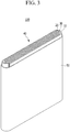
- FIG. 3 is an exploded perspective view of a rechargeable lithium battery according to an embodiment.
- a rechargeable lithium battery according to an embodiment may be a cylindrical battery.
- a rechargeable lithium battery 100 includes an electrode assembly 40 manufactured by winding a separator 30 interposed between a positive electrode 10 and a negative electrode 20, and a case 50 housing the electrode assembly 40.
- a Cu foil was disposed on a magnet having a magnetic field strength of 4000 Gauss, and the negative active material slurry was coated on the Cu foil while the Cu foil was moved and then, exposed to a magnetic field for 9 seconds, dried, and compressed to manufacture a negative electrode having a loading level (L/L) of 12 mg/cm 2 on one side of the current collector.
- 96 wt% of a LiC O 0 2 positive active material, 2 wt% of a carbon black conductive agent, and 2 wt% of a polyvinylidene fluoride binder were mixed in an N-methylpyrrolidone solvent to prepare positive active material slurry.
- the slurry was coated on an Al substrate, dried, and compressed to manufacture a positive electrode.
- the negative and positive electrodes and an electrolyte were used to manufacture a pouch-type full rechargeable lithium battery cell having capacity of 550 mAh and current density of 4.16 mAh/cm 2 .
- the electrolyte was prepared by using a mixed solvent of ethylene carbonate and diethyl carbonate (50 : 50 of a volume ratio) and dissolving 1 M LiPF 6 therein.
- a pouch-type rechargeable lithium battery cell was manufactured according to the same method as Example 1 by manufacturing the negative electrode having a loading level (L/L) of 12 mg/cm 2 on one side of the current collector except for changing the exposure time to a magnetic field from 9 seconds to 3 seconds.
- L/L loading level
- a pouch-type rechargeable lithium battery cell was manufactured according to the same method as Example 1 by manufacturing the negative electrode having a loading level (L/L) of 12 mg/cm 2 on one side of the current collector except for changing the exposure time to a magnetic field from 9 seconds to 5 seconds.
- L/L loading level
- a pouch-type rechargeable lithium battery cell was manufactured according to the same method as Example 1 by manufacturing the negative electrode having a loading level (L/L) of 12 mg/cm 2 on one side of the current collector except for changing the magnetic field strength from 4000 Gauss to 5000 Gauss.
- the negative active material slurry was coated on a Cu foil, dried, and compressed to manufacture a negative electrode having a loading level (L/L) of 12 mg/cm 2 on one side of the current collector.
- the negative electrode was used along with the positive electrode and the electrolyte solution used in Example 1 to manufacture a pouch-type rechargeable lithium battery cell.
- a pouch-type rechargeable lithium battery cell was manufactured according to the same method as Example 1 by manufacturing the negative electrode having a loading level (L/L) of 12 mg/cm 2 on one side of the current collector except for changing the exposure time to a magnetic field from 9 seconds to 2 seconds.
- L/L loading level
- a pouch-type rechargeable lithium battery cell was manufactured according to the same method as Example 1 by manufacturing the negative electrode having aloading level (L/L) of 12 mg/cm 2 on one side of the current collector except for changing the exposure time to a magnetic field from 9 seconds to 10 seconds and the magnetic field strength from 4000 Gauss to 5000 Gauss.
- L/L loading level
- a pouch-type rechargeable lithium battery cell was manufactured according to the same method as Example 1 by manufacturing the negative electrode having a loading level (L/L) of 12 mg/cm 2 on one side of the current collector except for changing the exposure time to a magnetic field from 9 seconds to 2 seconds and viscosity of the negative active material slurry from 2300 cps to 2700 cps.
- L/L loading level
- a pouch-type rechargeable lithium battery cell was manufactured according to the same method as Example 1 by manufacturing the negative electrode having a loading level (L/L) of 12 mg/cm 2 on one side of the current collector except for changing the magnetic field strength from 4000 Gauss to 3800 Gauss.
- a pouch-type rechargeable lithium battery cell was manufactured according to the same method as Example 1 by manufacturing the negative electrode having a loading level (L/L) of 12 mg/cm 2 on one side of the current collector except for changing the exposure time to a magnetic field strength from 9 seconds to 1 second.
- L/L loading level
- a Cu foil was disposed on a magnet having a magnetic field strength of 4000 Gauss, and the negative active material slurry was coated on the Cu foil while the Cu foil was moved and then, exposed to a magnetic field for 9 seconds, dried, and compressed to manufacture a negative electrode having a loading level (L/L) of 12 mg/cm 2 on one side of the current collector.
- 96 wt% of a LiCoO 2 positive active material, 2 wt% of a carbon black conductive agent, and 2 wt% of a polyvinylidene fluoride binder were mixed in an N-methylpyrrolidone solvent to prepare positive active material slurry.
- the slurry was coated on an Al substrate, dried, and compressed to manufacture a positive electrode.
- the negative and positive electrodes were used along with an electrolyte to manufacture a cylindrical full rechargeable lithium battery cell having capacity of 2.5 A.
- the electrolyte was prepared by dissolving 1 M LiPF 6 in a mixed solvent of ethylene carbonate and diethyl carbonate (50 : 50 of a volume ratio).
- the negative active material slurry was coated on a Cu foil, dried, and compressed to manufacture a negative electrode having a loading level (L/L) of 12 mg/cm 2 on one side of the current collector.
- the negative electrode was used along with the positive electrode and the electrolyte used in Example 6 to manufacture a cylindrical rechargeable lithium battery cell having capacity of 2.5 A.
- a cylindrical rechargeable lithium battery was manufactured according to the same method as Comparative Example 2 by manufacturing the negative electrode having a loading level (L/L) of 12 mg/cm 2 on one side of the current collector except for changing the exposure time to a magnetic field from 2 seconds to 1.5 seconds and viscosity of the negative active material slurry from 2300 cps to 2700 cps.
- L/L loading level
- the rechargeable lithium battery cells according to Example 1 and Comparative Example 1 were twice charged and discharged at 0.1 C and then completely discharged to 2.75 V at 0.1 C.
- the completely-discharged battery cells were disassembled to obtain negative electrodes.
- negative electrodes an X'Pert (PANalytical B.V.) XRD equipment using a CuK ⁇ ray as a target ray was used, but a monochromator equipment was removed in order to improve a peak intensity resolution.
- Example 1 The measured XRD results are shown in FIG. 4 (Example 1) and FIG. 5 (Comparative Example 1).
- I (004) /I (002) and I (110) /I (004( were calculated and are shown in Table 1.
- the negative electrode of Example 1 showed a DD value of greater than or equal to about 19, but the negative electrode of Comparative Example 1 showed a DD value of less than 19, and the negative electrode of Example 1 showed I (004) /I (002) of greater than or equal to 0.04, but the negative electrode of Comparative Example 1 showed I (004) /I (002) of less than 0.04.
- the negative electrode of Example 1 showed I( 110) /I (004) of greater than or equal to 0.3, while the negative electrode of Comparative Example 1 showed I( 110) /I (004) of less than 0.3.
- the negative electrodes of Examples 2 to 5 showed a DD value of greater than or equal to about 19 and less than or equal to about 60 and I (004) /I (002) of greater than or equal to 0.04, while the negative electrodes of Comparative Examples 2 to 4 and Reference Example 1 showed a DD value of less than 19 (Comparative Examples 2 and 4) or greater than 60 (Comparative Example 3) and I (004) /I (002) of less than 0.04 (Reference Example 1).
- the rechargeable lithium battery cells according to Examples 1 to 6, Comparative Examples 1 to 5, and Reference Example 1 were charged and discharged at 0.1 C and completely discharged to 3 V and then, disassembled to obtain negative electrodes.
- the negative electrodes were respectively used to obtain each 5 cm X 5 cm size sample, these samples were respectively cut into a size of 0.5 cm X 0.5 cm and put in a BET sample holder, and then, their BET's were measured in a nitrogen gas adsorption method, and the results are shown in Table 3.
- the rechargeable lithium battery cells according to Examples 2 to 5, Comparative Examples 2 to 4, and Reference Example 1 were evaluated under a 0.1 C charge and discharge condition, and their discharge capacity was first confirmed and regarded as a 1 C reference.
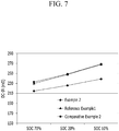
- DC internal resistance (DC-IR) was evaluated by 0.025 C cut-off charging the battery cells at 0.7 C under CCCV (constant current/constant voltage) and discharging the battery cells at 0.1 C and measuring a voltage drop (V) while a current flew at 1 C for 1 second under a SOC condition such as SOC70 (charged to be 70 % of charge capacity based on 100 % of entire battery charge capacity, which is 30 % discharged in a discharge state), SOC20 (charged to be 20 % of charge capacity based on 100 % of entire battery charge capacity, which is 80 % discharged in a discharge state), and SOC10 (charged to be 10 % of charge capacity based on 100 % of entire battery charge capacity, which is 90 % discharged in a discharge state).
- SOC70 charged to be 70 % of charge capacity based on 100 % of entire battery charge capacity, which is 30 % discharged in a discharge state
- SOC20 charged to be 20 % of charge capacity based on 100
- the negative electrodes of Examples 2 and 3 showed a DD value of greater than or equal to about 19 but less than or equal to about 60 and thus lower DC internal resistance under the SOC condition than Comparative Examples 2 and 3 and Reference Example 1.
- Example 5 showed a lower ratio of DC internal resistance at SOC10 relative to DC internal resistance at SOC70 than Comparative Example 4, and it shown from the results that that DC internal resistance was less increased according to a charge state.
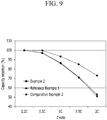
- the negative electrodes of Examples 2 and 3 showed a DD value of greater than or equal to about 19 but less than or equal to 60 and thus excellent capacity retention at all C-rates compared with the negative electrodes of Comparative Examples 2 to 4.
- Examples 2 to 4, Comparative Examples 2 and 3, and Reference Example 1 were respectively constant current/constant voltage charged under a condition of 1.0 C, 4.4 V, and 0.1 C cut-off, paused for 5 minutes, constant current discharged under a condition of 1.0 C and 3.0 V cut-off and paused for 5 minutes as a one cycle, and this cycle was 400 times repeated.
- a capacity retention depending on a charge and discharge cycle was evaluated by calculating a discharge capacity ratio at each cycle relative to discharge capacity at the first cycle, and the results are shown in FIG. 10 .
- the negative electrodes of Example 2 and 3 showing a DD value of greater than or equal to about 19 but less than or equal to 60 maintained a capacity retention of greater than or equal to 80 % even at the 400 th cycle
- the negative electrode of Comparative Example 2 showed a capacity retention of less than 80 % even at the 100 th cycle
- the negative electrode of Reference Example 1 showed a capacity retention of less than 80 % even at the 230 th cycle
- the negative electrode of Comparative Example 3 showed a capacity retention of less than 80 % even at the 330 th cycle, and that is, the capacity retention was rapidly decreased.
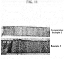
- the rechargeable lithium battery cells according to Comparative Example 2 and Example 3 were full-charged at 0.7 C, and then, after disassembling the negative electrodes therefrom, a lithium precipitation on the surface of negative electrodes was examined. The results are shown in FIG. 11 . As shown in FIG. 11 , the lithium precipitation was found on the surface of the negative electrode of Comparative Example 2, while the lithium precipitation was not found on the surface of the negative electrode of Example 3. As shown above, no lithium precipitation means that there is small resistance when lithium ions are inserted into a negative electrode.
- the suppressed lithium precipitation may improve battery stability and suppress depletion of an electrolyte solution due to continuous decomposition of the electrolyte solution and thus, improve battery electrochemical characteristics such as a cycle-life.
- the rechargeable lithium battery cells according to Example 5 and Comparative Example 4 were evaluated under a 0.1 C charge and discharge condition, and herein, discharge capacity of the cells was confirmed and regarded as a 1 C reference.
- the battery cells were 0.025 C cut-off charged at 0.7 C under CCCV (constant current constant voltage) and discharged at 0.1 C, then, cut-off at 0.7 C CCCV and 0.025 C, and then, fully charged to be SOC100 (charged to be 100 % of charge capacity based on 100 % of entire battery charge capacity, which is 0 % discharged) and disassembled to measure thickness of each electrode plate in the full charge state, and this thickness was compared with the thickness of the electrode plate after compression and vacuum-drying.
- Table 5 Swelling ratio (SOC100, %) Comparative Example 4 19.4
- the rechargeable lithium battery cell of Example 5 showed a smaller swelling ratio than that of Comparative Example 4, and the reason is that an electrode is oriented non-parallel to a current collector and thus contracted and expanded in X-axis and Y-axis directions rather than a Z-axis direction during repetitive charges and discharges, unlike a conventional electrode oriented parallel to a current collector and thus contracted and expanded in the Z-axis direction during repetitive charges and discharges.
- the electrode when the electrode is completely vertically oriented with the current collector, the electrode is contracted and expanded in the X-axis and Y-axis directions and thus may cause deformation of a battery cell, but the cell of Example 5 was not deformed since the cell had no completely vertical orientation.
- Thermal diffusivity of the negative electrodes according to Example 5 and Comparative Example 1 was measured, and the results are shown in FIG. 12 .
- the thermal diffusivity was measured in a Xenon flash method.
- the xenon flash method was performed according to ASTM E1461 by locating a negative electrode inside a furnace maintained at 25 °C, radiating xenon flashlight on one surface of the negative electrode with energy of 10 J/pulse to heat the negative electrode, and then, measuring the thermal diffusivity with a nitrogen-cooled InSb IR detector when a temperature was increased in an opposite of the negative electrode, and herein, a LFA-447 (NETZSCH, Germany) equipment was used.
- the penetration experiment was performed by respectively charging the rechargeable lithium battery cells at 0.5 C up to 4.2 V for 3 hours, pausing for about 10 minutes (up to 72 hours), and then, penetrating the center of the cells with a pin having a diameter of 5 mm at 60 Mm/sec.
- Example 5 showed 38 % improved thermal diffusivity and thus easily discharged heat generated thereby compared with Comparative Example 1.
- Table 6 OK (L1 mode) NG (L4 mode) Comparative Example 1 6 cells 4 cells
- Example 5 showed excellent battery safety compared with Comparative Example 1.
- FIG. 12 shows that the negative electrode of Example 5 showed higher thermal diffusivity than the negative electrode of Comparative Example 1 and thus fast discharged heat generated during the penetration and was suppressed from ignition due to thermal runaway.
- Example 6 Surface temperature of the cylindrical rechargeable lithium battery cells according to Example 6 and Comparative Example 5 was measured, while the cells were discharged with a 30 A constant current at 12 C, and the results are shown in Table 7. Table 7 Maximum temperature (°C) Comparative Example 5 120 Example 6 100
- Example 6 showed a lower maximum temperature during the discharge than Comparative Example 5, and the reason, as shown in FIG. 12 , is that the negative electrode of Example 5 showed higher thermal diffusivity than Comparative Example 1 and thus fast discharged heat generated during the penetration and also was suppressed from a battery temperature increase.
Applications Claiming Priority (1)
| Application Number | Priority Date | Filing Date | Title |
|---|---|---|---|
| KR1020160144621A KR102484406B1 (ko) | 2016-11-01 | 2016-11-01 | 리튬 이차 전지용 음극 및 이를 포함하는 리튬 이차 전지 |
Publications (1)
| Publication Number | Publication Date |
|---|---|
| EP3316378A1 true EP3316378A1 (fr) | 2018-05-02 |
Family
ID=60201462
Family Applications (1)
| Application Number | Title | Priority Date | Filing Date |
|---|---|---|---|
| EP17199464.3A Pending EP3316378A1 (fr) | 2016-11-01 | 2017-10-31 | Électrode négative comprenant du graphite partiellement orienté sur collecteur de courant pour batterie rechargeable au lithium, et batterie rechargeable au lithium |
Country Status (4)
| Country | Link |
|---|---|
| US (1) | US10629892B2 (fr) |
| EP (1) | EP3316378A1 (fr) |
| KR (1) | KR102484406B1 (fr) |
| CN (1) | CN108023064B (fr) |
Cited By (1)
| Publication number | Priority date | Publication date | Assignee | Title |
|---|---|---|---|---|
| EP3813160A4 (fr) * | 2018-08-17 | 2021-09-01 | Lg Chem, Ltd. | Matériau actif d'anode, procédé de préparation de matériau actif d'anode, anode et accumulateur comprenant l'anode |
Families Citing this family (15)
| Publication number | Priority date | Publication date | Assignee | Title |
|---|---|---|---|---|
| KR102484406B1 (ko) | 2016-11-01 | 2023-01-02 | 삼성에스디아이 주식회사 | 리튬 이차 전지용 음극 및 이를 포함하는 리튬 이차 전지 |
| KR102417267B1 (ko) | 2016-11-02 | 2022-07-04 | 삼성에스디아이 주식회사 | 리튬 이차 전지 |
| KR102657578B1 (ko) * | 2016-11-30 | 2024-04-15 | 삼성에스디아이 주식회사 | 이차 전지용 음극 및 이를 포함하는 이차 전지 |
| KR102417774B1 (ko) | 2018-04-20 | 2022-07-05 | 삼성에스디아이 주식회사 | 리튬 이차 전지용 음극 및 이를 포함하는 리튬 이차 전지 |
| KR102417773B1 (ko) | 2018-04-27 | 2022-07-05 | 삼성에스디아이 주식회사 | 리튬 이차 전지용 음극 및 이를 포함하는 리튬 이차 전지 |
| CN109494349B (zh) | 2018-10-17 | 2020-08-28 | 宁德时代新能源科技股份有限公司 | 负极极片及二次电池 |
| CN109524670A (zh) * | 2018-11-12 | 2019-03-26 | 溧阳中科海钠科技有限责任公司 | 一种二次电池正极浆料、正极极片和二次电池 |
| KR102365086B1 (ko) * | 2018-12-03 | 2022-02-18 | 주식회사 엘지에너지솔루션 | 비파괴적 활물질의 활성 면적 측정 방법 |
| KR102570570B1 (ko) * | 2019-04-24 | 2023-08-23 | 삼성에스디아이 주식회사 | 리튬 이차 전지용 음극 및 이를 포함하는 리튬 이차 전지 |
| KR102536366B1 (ko) * | 2019-04-24 | 2023-05-23 | 삼성에스디아이 주식회사 | 리튬 이차 전지용 음극 및 이를 포함하는 리튬 이차 전지 |
| CN111122627A (zh) * | 2019-12-19 | 2020-05-08 | 东莞维科电池有限公司 | 一种石墨负极片最优压实密度的测试方法 |
| CN114628625A (zh) * | 2020-06-04 | 2022-06-14 | 宁德新能源科技有限公司 | 负极活性材料及使用其的电化学装置和电子装置 |
| KR20240037545A (ko) * | 2022-09-15 | 2024-03-22 | 주식회사 엘지에너지솔루션 | 음극용 자성 정렬 장치 및 이를 이용한 음극의 제조방법 |
| KR20240037551A (ko) * | 2022-09-15 | 2024-03-22 | 주식회사 엘지에너지솔루션 | 음극용 자성 정렬 장치 및 이를 이용한 음극의 제조방법 |
| KR102630468B1 (ko) * | 2023-03-13 | 2024-01-29 | 주식회사 엘지에너지솔루션 | 리튬 이차전지용 음극 및 이의 제조방법 |
Citations (7)
| Publication number | Priority date | Publication date | Assignee | Title |
|---|---|---|---|---|
| KR20030052949A (ko) | 2001-12-21 | 2003-06-27 | 삼성에스디아이 주식회사 | 흑연함유 조성물, 리튬 이차 전지용 음극, 및 리튬 이차전지 |
| US20120021294A1 (en) * | 2010-07-22 | 2012-01-26 | Aruna Zhamu | Graphite or carbon particulates for the lithium ion battery anode |
| WO2012039041A1 (fr) | 2010-09-22 | 2012-03-29 | トヨタ自動車株式会社 | Batterie secondaire à électrolyte non aqueux |
| EP2538484A1 (fr) * | 2011-06-20 | 2012-12-26 | Samsung SDI Co., Ltd. | Matériau actif négatif pour batterie au lithium rechargeable, procédé de préparation de celui-ci, et électrode négative et batterie au lithium rechargeable comprenant celui-ci |
| EP2660903A1 (fr) * | 2012-04-30 | 2013-11-06 | Samsung SDI Co., Ltd. | Composition d'électrode négative pour batterie rechargeable au lithium, électrode négative comprenant celle-ci et batterie au lithium rechargeable comprenant ladite électrode |
| US20150030931A1 (en) * | 2011-12-14 | 2015-01-29 | Koji Takahata | Non-aqueous electrolyte secondary battery and method for manufacturing negative electrode for secondary battery |
| KR101669110B1 (ko) | 2011-01-12 | 2016-10-26 | 삼성에스디아이 주식회사 | 음극 활물질 조성물, 이를 이용한 음극 극판의 제조방법 및 리튬 이차 전지 |
Family Cites Families (39)
| Publication number | Priority date | Publication date | Assignee | Title |
|---|---|---|---|---|
| JPS5315687A (en) | 1976-07-29 | 1978-02-13 | Mitsubishi Metal Corp | Cutting tool with replacing device of cutting blade |
| JP4016464B2 (ja) * | 1997-09-30 | 2007-12-05 | ソニー株式会社 | ゲル電解質二次電池 |
| JP4193267B2 (ja) | 1999-02-23 | 2008-12-10 | ソニー株式会社 | 固体電解質電池 |
| JP3466576B2 (ja) * | 2000-11-14 | 2003-11-10 | 三井鉱山株式会社 | リチウム二次電池負極用複合材料及びリチウム二次電池 |
| KR100632979B1 (ko) | 2000-11-16 | 2006-10-11 | 히다치 막셀 가부시키가이샤 | 리튬 함유 복합 산화물 및 이것을 이용한 비수 2차 전지,및 그 제조 방법 |
| US7326497B2 (en) | 2001-12-21 | 2008-02-05 | Samsung Sdi Co., Ltd. | Graphite-containing composition, negative electrode for a lithium secondary battery, and lithium secondary battery |
| JP4150516B2 (ja) | 2001-12-21 | 2008-09-17 | 三星エスディアイ株式会社 | リチウム二次電池の負極用の黒鉛含有組成物の製造方法並びにリチウム二次電池用の負極の製造方法及びリチウム二次電池の製造方法 |
| US20070128518A1 (en) | 2004-02-12 | 2007-06-07 | Mitsubishi Chemical Corporation | Negative electrode material for lithium secondary battery, method for producing same, negative electrode for lithium secondary battery using same, and lithium secondary battery |
| JP3705801B1 (ja) | 2004-03-29 | 2005-10-12 | シャープ株式会社 | リチウムイオン二次電池 |
| GB2412484B (en) | 2004-07-27 | 2006-03-22 | Intellikraft Ltd | Improvements relating to electrode structures in batteries |
| US20060024579A1 (en) | 2004-07-27 | 2006-02-02 | Vladimir Kolosnitsyn | Battery electrode structure and method for manufacture thereof |
| JP4992426B2 (ja) | 2004-08-30 | 2012-08-08 | 三菱化学株式会社 | 非水系二次電池用負極材料、非水系二次電池用負極、および非水系二次電池 |
| US8999580B2 (en) * | 2005-12-21 | 2015-04-07 | Show A Denko K.K. | Composite graphite particles and lithium rechargeable battery using the same |
| KR100912788B1 (ko) | 2006-09-11 | 2009-08-18 | 주식회사 엘지화학 | 우수한 펄스 방전 특성의 전극조립체 |
| KR20080095562A (ko) * | 2007-04-25 | 2008-10-29 | 삼성에스디아이 주식회사 | 리튬 이차전지의 음극 및 이를 이용한 리튬 이차전지 |
| JP5167703B2 (ja) | 2007-06-20 | 2013-03-21 | 日産自動車株式会社 | 電池用電極 |
| US20120196193A1 (en) * | 2009-03-02 | 2012-08-02 | Ls Mtron Ltd. | Composite graphite particles and lithium secondary battery using the same |
| WO2012011189A1 (fr) | 2010-07-23 | 2012-01-26 | トヨタ自動車株式会社 | Batterie secondaire aux ions de lithium |
| JP2012033375A (ja) | 2010-07-30 | 2012-02-16 | Mitsubishi Chemicals Corp | 非水系二次電池用炭素材料 |
| CN103250281B (zh) | 2010-12-06 | 2015-08-05 | 丰田自动车株式会社 | 锂离子二次电池的制造方法 |
| JP5652682B2 (ja) | 2011-03-11 | 2015-01-14 | トヨタ自動車株式会社 | 非水電解質二次電池とその製造方法 |
| KR101195081B1 (ko) | 2011-04-29 | 2012-10-29 | 한국에너지기술연구원 | 고전기전도성, 고내구성을 갖는 탄소 코팅 알루미늄 집전체 및 그 제조방법 |
| JP2013069432A (ja) | 2011-09-20 | 2013-04-18 | Toyota Motor Corp | リチウムイオン二次電池とその製造方法 |
| WO2013108516A1 (fr) | 2012-01-20 | 2013-07-25 | トヨタ自動車株式会社 | Élément électrode et son procédé de fabrication |
| EP2869389B1 (fr) | 2012-06-29 | 2019-11-13 | Mitsubishi Chemical Corporation | Solution électrolytique non aqueuse et cellule de solution électrolytique non aqueuse l'utilisant |
| JP5993337B2 (ja) | 2012-07-03 | 2016-09-14 | Jfeケミカル株式会社 | リチウムイオン二次電池用負極材料およびその製造方法ならびにこれを用いたリチウムイオン二次電池用負極ならびにリチウムイオン二次電池 |
| JP6233688B2 (ja) | 2012-09-13 | 2017-11-22 | 株式会社Gsユアサ | 電極体、電極体の製造方法、及び電極体を備えた蓄電素子 |
| KR101582718B1 (ko) | 2013-02-04 | 2016-01-06 | 주식회사 엘지화학 | 구형 천연 흑연을 포함하는 음극 및 이를 포함하는 리튬 이차 전지 |
| KR101599322B1 (ko) | 2013-07-02 | 2016-03-03 | 삼성에스디아이 주식회사 | 양극 활물질과 활성탄의 입경 비율이 제어된 리튬 이차 전지 |
| JP2015138644A (ja) | 2014-01-22 | 2015-07-30 | トヨタ自動車株式会社 | 非水電解質二次電池 |
| JP2014096386A (ja) | 2014-01-24 | 2014-05-22 | Toyota Motor Corp | リチウムイオン二次電池 |
| JP2016131123A (ja) | 2015-01-14 | 2016-07-21 | 株式会社日立製作所 | リチウム二次電池、リチウム二次電池を含む蓄電装置、およびリチウム二次電池の製造方法 |
| JP7108372B2 (ja) | 2015-06-18 | 2022-07-28 | 帝人株式会社 | 非水電解質二次電池用電極合剤層、非水電解質二次電池用電極及び非水電解質二次電池 |
| PL3312316T3 (pl) | 2015-06-18 | 2020-12-14 | Teijin Limited | Węgiel włóknisty, sposób jego wytwarzania, warstwa mieszaniny elektrodowej do baterii akumulatorowej z niewodnym elektrolitem, elektroda w baterii akumulatorowej z niewodnym elektrolitem oraz bateria akumulatorowa z niewodnym elektrolitem |
| KR20170002302A (ko) | 2015-06-29 | 2017-01-06 | 신닛테츠 수미킨 가가쿠 가부시키가이샤 | 리튬이온 이차전지용 부극 및 이차전지 |
| KR20180007618A (ko) | 2016-07-13 | 2018-01-23 | 삼성에스디아이 주식회사 | 리튬 이차 전지용 음극 활물질 및 이를 포함하는 리튬 이차 전지 |
| KR102484406B1 (ko) | 2016-11-01 | 2023-01-02 | 삼성에스디아이 주식회사 | 리튬 이차 전지용 음극 및 이를 포함하는 리튬 이차 전지 |
| JP2017063040A (ja) | 2016-11-01 | 2017-03-30 | 昭和電工株式会社 | リチウムイオン電池用負極材及びその用途 |
| KR102417267B1 (ko) | 2016-11-02 | 2022-07-04 | 삼성에스디아이 주식회사 | 리튬 이차 전지 |
-
2016
- 2016-11-01 KR KR1020160144621A patent/KR102484406B1/ko active IP Right Grant
-
2017
- 2017-10-31 EP EP17199464.3A patent/EP3316378A1/fr active Pending
- 2017-10-31 US US15/799,238 patent/US10629892B2/en active Active
- 2017-11-01 CN CN201711054967.8A patent/CN108023064B/zh active Active
Patent Citations (8)
| Publication number | Priority date | Publication date | Assignee | Title |
|---|---|---|---|---|
| KR20030052949A (ko) | 2001-12-21 | 2003-06-27 | 삼성에스디아이 주식회사 | 흑연함유 조성물, 리튬 이차 전지용 음극, 및 리튬 이차전지 |
| US20120021294A1 (en) * | 2010-07-22 | 2012-01-26 | Aruna Zhamu | Graphite or carbon particulates for the lithium ion battery anode |
| WO2012039041A1 (fr) | 2010-09-22 | 2012-03-29 | トヨタ自動車株式会社 | Batterie secondaire à électrolyte non aqueux |
| US20130177792A1 (en) | 2010-09-22 | 2013-07-11 | Koji Takahata | Nonaqueous electrolyte secondary battery |
| KR101669110B1 (ko) | 2011-01-12 | 2016-10-26 | 삼성에스디아이 주식회사 | 음극 활물질 조성물, 이를 이용한 음극 극판의 제조방법 및 리튬 이차 전지 |
| EP2538484A1 (fr) * | 2011-06-20 | 2012-12-26 | Samsung SDI Co., Ltd. | Matériau actif négatif pour batterie au lithium rechargeable, procédé de préparation de celui-ci, et électrode négative et batterie au lithium rechargeable comprenant celui-ci |
| US20150030931A1 (en) * | 2011-12-14 | 2015-01-29 | Koji Takahata | Non-aqueous electrolyte secondary battery and method for manufacturing negative electrode for secondary battery |
| EP2660903A1 (fr) * | 2012-04-30 | 2013-11-06 | Samsung SDI Co., Ltd. | Composition d'électrode négative pour batterie rechargeable au lithium, électrode négative comprenant celle-ci et batterie au lithium rechargeable comprenant ladite électrode |
Non-Patent Citations (1)
| Title |
|---|
| JULIETTE BILLAUD; BOUVILLE FLORIAN; MAGRINI TOMMASO; VILLEVIEILLE CLAIRE; STUDART ANDRÉ R: "Magnetically aligned graphite electrodes for high-rate performance Li-ion batteries", NATURE ENERGY, vol. 1, 16097, 2016, pages 1 - 6, XP055477548 |
Cited By (2)
| Publication number | Priority date | Publication date | Assignee | Title |
|---|---|---|---|---|
| EP3813160A4 (fr) * | 2018-08-17 | 2021-09-01 | Lg Chem, Ltd. | Matériau actif d'anode, procédé de préparation de matériau actif d'anode, anode et accumulateur comprenant l'anode |
| US11894548B2 (en) | 2018-08-17 | 2024-02-06 | Lg Energy Solution, Ltd. | Negative electrode active material, method of preparing the negative electrode active material, negative electrode, and secondary battery including the negative electrode |
Also Published As
| Publication number | Publication date |
|---|---|
| CN108023064B (zh) | 2021-10-08 |
| CN108023064A (zh) | 2018-05-11 |
| KR20180047846A (ko) | 2018-05-10 |
| US20180123120A1 (en) | 2018-05-03 |
| US10629892B2 (en) | 2020-04-21 |
| KR102484406B1 (ko) | 2023-01-02 |
Similar Documents
| Publication | Publication Date | Title |
|---|---|---|
| US10629892B2 (en) | Negative electrode for rechargeable lithium battery, and rechargeable lithium battery including same | |
| EP3734704A1 (fr) | Batterie rechargeable au lithium | |
| US11108044B2 (en) | Rechargeable lithium battery | |
| EP3591737A1 (fr) | Batterie rechargeable au lithium | |
| US20120045693A1 (en) | Negative active material for rechargeable lithium battery, method of preparing same, and rechargeable lithium battery including same | |
| EP3961758A1 (fr) | Électrode négative de batterie secondaire au lithium et batterie secondaire au lithium la comprenant | |
| EP2498329A1 (fr) | Électrolyte non aqueux pour batterie rechargeable au lithium et batterie rechargeable au lithium l'incluant | |
| EP3537517A2 (fr) | Électrode positive pour batterie rechargeable au lithium et batterie rechargeable au lithium la comprenant | |
| US8642215B2 (en) | Negative active material for rechargeable lithium battery, method of preparing the same and rechargeable lithium battery including the same | |
| EP2432050A1 (fr) | Matériau actif négatif pour batterie au lithium rechargeable et batterie au lithium rechargeable lýincluant | |
| EP3961759A1 (fr) | Anode pour batterie secondaire au lithium et batterie secondaire au lithium la comprenant | |
| US20220029153A1 (en) | Negative electrode for a rechargeable lithium battery | |
| US20150207174A1 (en) | Electrolyte and rechargeable lithium battery including same | |
| US20230369593A1 (en) | Negative electrode for a rechargeable lithium battery and rechargeable lithium battery including the same | |
| US20170117546A1 (en) | Negative active material for rechargeable lithium battery, and rechargeable lithium battery including same | |
| EP4080604A2 (fr) | Électrode négative pour batterie rechargeable au lithium et batterie rechargeable au lithium la comprenant | |
| US11424485B2 (en) | Lithium secondary battery electrolyte and lithium secondary battery comprising same | |
| EP3553851B1 (fr) | Ensemble d'électrode et batterie rechargeable le comprenant | |
| US20230352651A1 (en) | Rechargeable electrode for rechargeable lithium battery and rechargeable lithium battery including the same | |
| KR102665405B1 (ko) | 리튬 이차 전지용 음극 및 이를 포함하는 리튬 이차 전지 |
Legal Events
| Date | Code | Title | Description |
|---|---|---|---|
| PUAI | Public reference made under article 153(3) epc to a published international application that has entered the european phase |
Free format text: ORIGINAL CODE: 0009012 |
|
| STAA | Information on the status of an ep patent application or granted ep patent |
Free format text: STATUS: REQUEST FOR EXAMINATION WAS MADE |
|
| 17P | Request for examination filed |
Effective date: 20171031 |
|
| AK | Designated contracting states |
Kind code of ref document: A1 Designated state(s): AL AT BE BG CH CY CZ DE DK EE ES FI FR GB GR HR HU IE IS IT LI LT LU LV MC MK MT NL NO PL PT RO RS SE SI SK SM TR |
|
| AX | Request for extension of the european patent |
Extension state: BA ME |
|
| STAA | Information on the status of an ep patent application or granted ep patent |
Free format text: STATUS: EXAMINATION IS IN PROGRESS |
|
| TPAC | Observations filed by third parties |
Free format text: ORIGINAL CODE: EPIDOSNTIPA |
|
| 17Q | First examination report despatched |
Effective date: 20210610 |
|
| STAA | Information on the status of an ep patent application or granted ep patent |
Free format text: STATUS: EXAMINATION IS IN PROGRESS |