EP3313613B1 - Procédés de traitement post-moulage d'un dispositif venturi - Google Patents
Procédés de traitement post-moulage d'un dispositif venturi Download PDFInfo
- Publication number
- EP3313613B1 EP3313613B1 EP16815232.0A EP16815232A EP3313613B1 EP 3313613 B1 EP3313613 B1 EP 3313613B1 EP 16815232 A EP16815232 A EP 16815232A EP 3313613 B1 EP3313613 B1 EP 3313613B1
- Authority
- EP
- European Patent Office
- Prior art keywords
- blasting
- motive
- inlet
- media
- venturi
- Prior art date
- Legal status (The legal status is an assumption and is not a legal conclusion. Google has not performed a legal analysis and makes no representation as to the accuracy of the status listed.)
- Active
Links
- 238000000034 method Methods 0.000 title claims description 46
- 238000012545 processing Methods 0.000 title claims description 6
- 238000005422 blasting Methods 0.000 claims description 96
- CURLTUGMZLYLDI-UHFFFAOYSA-N Carbon dioxide Chemical compound O=C=O CURLTUGMZLYLDI-UHFFFAOYSA-N 0.000 claims description 4
- TWNQGVIAIRXVLR-UHFFFAOYSA-N oxo(oxoalumanyloxy)alumane Chemical group O=[Al]O[Al]=O TWNQGVIAIRXVLR-UHFFFAOYSA-N 0.000 claims description 3
- 229920000642 polymer Polymers 0.000 claims description 3
- 239000007787 solid Substances 0.000 claims description 3
- 229910002092 carbon dioxide Inorganic materials 0.000 claims description 2
- 239000001569 carbon dioxide Substances 0.000 claims description 2
- 239000000919 ceramic Substances 0.000 claims description 2
- 239000000428 dust Substances 0.000 claims description 2
- 239000012526 feed medium Substances 0.000 claims description 2
- 239000011521 glass Substances 0.000 claims description 2
- 229910052751 metal Inorganic materials 0.000 claims description 2
- 239000002184 metal Substances 0.000 claims description 2
- 239000002245 particle Substances 0.000 claims description 2
- 229910044991 metal oxide Inorganic materials 0.000 claims 2
- 150000004706 metal oxides Chemical class 0.000 claims 2
- 239000012530 fluid Substances 0.000 description 37
- 238000000465 moulding Methods 0.000 description 18
- 238000004891 communication Methods 0.000 description 14
- 230000008569 process Effects 0.000 description 10
- 239000003570 air Substances 0.000 description 9
- 238000004519 manufacturing process Methods 0.000 description 7
- 239000000463 material Substances 0.000 description 7
- 238000003754 machining Methods 0.000 description 6
- 238000007789 sealing Methods 0.000 description 6
- 239000011800 void material Substances 0.000 description 6
- 238000001746 injection moulding Methods 0.000 description 5
- 230000000087 stabilizing effect Effects 0.000 description 4
- 230000008901 benefit Effects 0.000 description 3
- 230000015572 biosynthetic process Effects 0.000 description 3
- 229910000831 Steel Inorganic materials 0.000 description 2
- 230000009286 beneficial effect Effects 0.000 description 2
- 238000002485 combustion reaction Methods 0.000 description 2
- 230000000694 effects Effects 0.000 description 2
- 239000007789 gas Substances 0.000 description 2
- 239000004033 plastic Substances 0.000 description 2
- 239000002952 polymeric resin Substances 0.000 description 2
- 239000010959 steel Substances 0.000 description 2
- 230000003746 surface roughness Effects 0.000 description 2
- 229920003002 synthetic resin Polymers 0.000 description 2
- 238000011144 upstream manufacturing Methods 0.000 description 2
- XLYOFNOQVPJJNP-UHFFFAOYSA-N water Substances O XLYOFNOQVPJJNP-UHFFFAOYSA-N 0.000 description 2
- 229920002292 Nylon 6 Polymers 0.000 description 1
- 239000012080 ambient air Substances 0.000 description 1
- 238000004873 anchoring Methods 0.000 description 1
- 230000002238 attenuated effect Effects 0.000 description 1
- 239000011324 bead Substances 0.000 description 1
- 238000007664 blowing Methods 0.000 description 1
- 230000008859 change Effects 0.000 description 1
- 239000000084 colloidal system Substances 0.000 description 1
- 238000007796 conventional method Methods 0.000 description 1
- 230000003247 decreasing effect Effects 0.000 description 1
- 230000009977 dual effect Effects 0.000 description 1
- 239000002223 garnet Substances 0.000 description 1
- 238000010438 heat treatment Methods 0.000 description 1
- 238000002347 injection Methods 0.000 description 1
- 239000007924 injection Substances 0.000 description 1
- 239000007788 liquid Substances 0.000 description 1
- 230000013011 mating Effects 0.000 description 1
- 238000012986 modification Methods 0.000 description 1
- 230000004048 modification Effects 0.000 description 1
- 239000003921 oil Substances 0.000 description 1
- 239000011148 porous material Substances 0.000 description 1
- 230000001681 protective effect Effects 0.000 description 1
- HBMJWWWQQXIZIP-UHFFFAOYSA-N silicon carbide Chemical compound [Si+]#[C-] HBMJWWWQQXIZIP-UHFFFAOYSA-N 0.000 description 1
- 229910010271 silicon carbide Inorganic materials 0.000 description 1
- 239000000725 suspension Substances 0.000 description 1
- 238000012360 testing method Methods 0.000 description 1
- 230000007704 transition Effects 0.000 description 1
- 238000013519 translation Methods 0.000 description 1
- 238000003466 welding Methods 0.000 description 1
Images


Classifications
-
- B—PERFORMING OPERATIONS; TRANSPORTING
- B24—GRINDING; POLISHING
- B24C—ABRASIVE OR RELATED BLASTING WITH PARTICULATE MATERIAL
- B24C3/00—Abrasive blasting machines or devices; Plants
- B24C3/32—Abrasive blasting machines or devices; Plants designed for abrasive blasting of particular work, e.g. the internal surfaces of cylinder blocks
- B24C3/325—Abrasive blasting machines or devices; Plants designed for abrasive blasting of particular work, e.g. the internal surfaces of cylinder blocks for internal surfaces, e.g. of tubes
-
- B—PERFORMING OPERATIONS; TRANSPORTING
- B24—GRINDING; POLISHING
- B24C—ABRASIVE OR RELATED BLASTING WITH PARTICULATE MATERIAL
- B24C11/00—Selection of abrasive materials or additives for abrasive blasts
-
- B—PERFORMING OPERATIONS; TRANSPORTING
- B24—GRINDING; POLISHING
- B24C—ABRASIVE OR RELATED BLASTING WITH PARTICULATE MATERIAL
- B24C3/00—Abrasive blasting machines or devices; Plants
- B24C3/32—Abrasive blasting machines or devices; Plants designed for abrasive blasting of particular work, e.g. the internal surfaces of cylinder blocks
- B24C3/325—Abrasive blasting machines or devices; Plants designed for abrasive blasting of particular work, e.g. the internal surfaces of cylinder blocks for internal surfaces, e.g. of tubes
- B24C3/327—Abrasive blasting machines or devices; Plants designed for abrasive blasting of particular work, e.g. the internal surfaces of cylinder blocks for internal surfaces, e.g. of tubes by an axially-moving flow of abrasive particles without passing a blast gun, impeller or the like along the internal surface
-
- B—PERFORMING OPERATIONS; TRANSPORTING
- B29—WORKING OF PLASTICS; WORKING OF SUBSTANCES IN A PLASTIC STATE IN GENERAL
- B29C—SHAPING OR JOINING OF PLASTICS; SHAPING OF MATERIAL IN A PLASTIC STATE, NOT OTHERWISE PROVIDED FOR; AFTER-TREATMENT OF THE SHAPED PRODUCTS, e.g. REPAIRING
- B29C37/00—Component parts, details, accessories or auxiliary operations, not covered by group B29C33/00 or B29C35/00
- B29C37/02—Deburring or deflashing
-
- B—PERFORMING OPERATIONS; TRANSPORTING
- B29—WORKING OF PLASTICS; WORKING OF SUBSTANCES IN A PLASTIC STATE IN GENERAL
- B29L—INDEXING SCHEME ASSOCIATED WITH SUBCLASS B29C, RELATING TO PARTICULAR ARTICLES
- B29L2031/00—Other particular articles
- B29L2031/748—Machines or parts thereof not otherwise provided for
- B29L2031/7506—Valves
Definitions
- This application relates to methods for post-mold processing a Venturi device, more particularly, removing flash from an interior surface of the same and/or forming a corner radius on any one or more inlets or outlets.
- Engines for example vehicle engines, are known to include aspirators or ejectors for producing vacuum and/or check valves.
- these components are formed from plastic that is molded, such as by injection molding techniques. Molding components is a cost effective way to manufacture the internal passageway(s) to desired geometries out of plastic material that can survive the operating conditions experienced in an engine system. Such a component is, for instance, described in US2011186151A1 .
- These molding techniques do have some shortcomings. Flash is commonly formed at the interface between the mold core pieces that form the internal passageway(s). This flash can interfere with the flow of fluid through the internal passageways, which is likely to reduce performance of the aspirators or ejectors and/or check valves.
- a second shortcoming is the general difficulty in forming a corner radius on inlets and outlets of the internal passageway(s) during the molding process.
- Molding techniques such as injection molding, tend to provide a surface finish that is generally quite smooth, including those internal surfaces formed by mold core pieces. However, there may be times when a different surface finish could be beneficial, in particular could improve performance of the component.
- What is needed is a method or methods that remove the flash, form a corner radius, and, optionally, modify the surface finish of internal passageways.
- a method for post-mold processing a Venturi device for generating vacuum is disclosed as claimed in the appended set of claims.
- fluid means any liquid, suspension, colloid, gas, plasma, or combinations thereof.
- FIG. 1 is an external view of a Venturi device, generally identified by reference number 100, for use in an engine, for example, in a vehicle's engine, that includes integral check valves 111, 120.
- the engine may be an internal combustion, and the vehicle and/or engine may include a device requiring vacuum. Venturi devices are often connected to an internal combustion engine before the engine throttle and after the engine throttle.
- the engine and all its components and/or subsystems are not shown in the figures, with the exception of a few boxes, as shown in FIG. 2 , included to represent specific components of the engine as identified herein, and it is understood that the engine components and/or subsystems may include any commonly found in vehicle engines.
- the Venturi device may be referred to as an aspirator.
- the Venturi device 100 may be referred to as an ejector.
- the Venturi device 100 could have the check valves 111 and 120 as separate components connected to a suction port and a bypass port, rather than as an integral part of thereof.
- the Venturi device 100 is connectable to a device requiring vacuum 102 to create vacuum for said device by the flow of air through a passageway 144, extending generally the length of a portion of the aspirator-check valve assembly, designed to create the Venturi effect.
- the Venturi device 100 includes a housing 101, which as illustrated is formed of an upper housing portion 104 and a lower housing portion 106.
- the designations of upper and lower portions are relative to the drawings as oriented on the page, for descriptive purposes, and are not limited to the illustrated orientation when utilized in an engine system.
- upper housing portion 104 is joined to lower housing portion 106 by sonic welding, heating, or other conventional methods for forming an airtight seal therebetween.
- the lower housing portion 106 defines passageway 144 which includes a plurality of ports, some of which are connectable to components or subsystems of the engine.
- the ports include: (1) a motive port 108; (2) a suction port 110, which can connect via the check valve 111 to a device requiring vacuum 102; (3) a discharge port 112; and, optionally, (4) a bypass port 114.
- Check valve 111 is preferably arranged to prevent fluid from flowing from the suction port 110 to the application device 102.
- the bypass port 114 may be connected to the device requiring vacuum 102 and, optionally, may include check valve 120 in the fluid flow path therebetween.
- Check valve 120 is preferably arranged to prevent fluid from flowing from the bypass port 114 to the application device 102.
- lower housing portions 106 in both embodiments includes lower valve seats 124, 126.
- Each lower valve seat 124, 126 is defined by a continuous outer wall 128, 129, and, optionally, a bottom wall such as wall 130 in lower valve seat 124.
- a bore 132, 133 is defined in each lower valve seat 124, 126, respectively, to allow for air flow communication with air passageway 144.
- each lower valve seat 124, 126 includes a plurality of radially spaced fingers 134, 135 extending upwardly from an upper surface thereof. The radially spaced fingers 134, 135 serve to support a seal member 136, 137.
- the upper housing portion 104 is configured for mating to or with the lower housing portion 106 to form the check valves 111, 120, if both are present.
- Upper housing portion 104 defines passageway 146 extending the length thereof and defines a plurality of ports, some of which are connectable to components or subsystems of the engine.
- the ports include: (1) a first port 148 that may be capped with cap 174 or may be connected to a component or subsystem of the engine; (2) a second port 150 (part of the inlet port for chamber/cavity 166) in fluid communication with the suction port 110 in the lower housing portion 106, and between which the seal member 136 is disposed; (3) a third port 152 (part of the inlet port for chamber/cavity 167) in fluid communication with the bypass port 114 in the lower housing portion 106, and between which the seal member 137 is disposed; and (4) a fourth port 154 which may function as an inlet connecting the aspirator-check valve assembly to a device requiring vacuum 102.
- the upper housing portion 104 in both embodiments includes upper valve seats 125, 127.
- Each upper valve seat 125, 127 is defined by continuous outer wall 160, 161 and bottom wall 162, 163.
- Both upper valve seats 125, 127 may include a pin 164, 165 extending downwardly from the bottom walls 162, 163, respectively, toward the lower housing portion 106.
- the pins 164, 165 function as a guide for translation of the sealing members 136, 137 within the cavities 166, 167 defined by the mated upper valve seat 125 with the lower valve seat 124 and defined by the mated upper valve seat 127 with the lower valve seat 126.
- each sealing member 136, 137 includes a bore therethrough sized and positioned therein for receipt of the pin 164, 165 within its respective cavity 166, 167.
- the passageway 144 in the lower housing portion 106 has an inner dimension along a central longitudinal axis that includes a first tapering portion 182 (also referred to herein as the motive cone) in the motive section 180 of the lower housing portion 106 coupled to a second tapering portion 183 (also referred to herein as the discharge cone) in the discharge section 181 of the lower housing portion 106.
- the first tapering portion 182 and the second tapering portion 183 are aligned end to end, having the motive outlet end 184 facing the discharge inlet end 186 and defining a Venturi gap 187 therebetween, which defines a fluid junction placing the suction port 110 in fluid communication with both the motive section 180 and the discharge section 181 of the inner passageway 144.
- the Venturi gap 187 as used herein means the lineal distance D between the motive outlet end 184 and the discharge inlet end 186.
- the inlet ends 188, 186 and the outlet end 184, 189 may be any circular shape, elliptical shape, or some other polygonal form and the gradually, continuously tapering inner dimension extending therefrom may define, but is not limited to, a hyperboloid or a cone.
- FIGS. 20-22 Some example configurations for the outlet end 184 of the motive section 180 and inlet end 186 of the discharge section 181 are presented in FIGS. 20-22 , which are from co-pending U.S. Patent Application No. 14/294,727, filed June 3, 2014 .
- FIGS. 20A-20B and 21A-21B illustrate embodiments with improved fluid junctions where the suction port 110 meets the motive outlet end 184 and the discharge inlet end 186.
- the smallest area of the flow path from the suction port 110 to the Venturi gap 187 is the frustum defined between the motive outlet end 184 and the discharge inlet end 186, see FIGS. 20B and 21B .
- the outlet end 184 of the motive cone 182 and the inlet end 186 of the discharge cone 183 each have inner and outer elliptical perimeters and thereby define a Venturi gap 187 that is a frustum having an elliptical outer periphery.
- FIGS. 20A-20B and 21A-21B illustrate embodiments with improved fluid junctions where the suction port 110 meets the motive outlet end 184 and the discharge inlet end 186.
- the smallest area of the flow path from the suction port 110 to the Venturi gap 187 is the frustum defined between the motive outlet end 184 and the discharge in
- the outlet end 184 of the motive cone 182 and the inlet end 186 of the discharge cone 183 each have inner and outer generally rectangular-shaped perimeters (with rounded corners) and thereby define a Venturi gap 187 that is a frustum having a generally rectangular-shaped outer periphery. While the embodiments in the figures have the same perimeter for the outlet end 184 and the inlet end 186, i.e., both are elliptical or both are generally rectangular, the outlet end 184 and the inlet end 186 may have differently shaped perimeters, i.e., one may be elliptical while the other is generally rectangular. Additionally, the motive outlet end 184 and the discharge inlet end 186 may terminate with a rounded chamfer to improve the directionality of the flow of the fluid from the suction port 110 in to the discharge inlet end 186.
- the outlet end 184 of the motive cone 182 for each embodiment is dimensionally smaller than the inlet end 186 of the discharge cone 183.
- This difference in dimension is identified as offset 140.
- the offset is seen in that the length of the major axis Y of the motive outlet end 184 is less than the length of the major axis Y' of the discharge inlet end 186 and may also have a length of the minor axis X of the motive outlet end 184 that is less than the length of the minor axis X' of the discharge inlet end 186.
- the elliptical- or polygonal-shaped internal cross-section of the motive outlet end of the converging motive section has a ratio of the major axis to the minor axis of about 2 to about 4, and the elliptical- or polygonal-shaped internal cross-section of the inlet end of the diverging discharge section is offset, relative to the elliptical- or polygonal-shaped internal cross-section of the outlet end of the converging motive section, by the ratio of the difference of the discharge inlet area and the motive outlet area to the peak motive flow rate, which is then multiplied by a constant ki to have a unitless ratio of greater than 0.28.
- Offset ratio discharge inlet area ⁇ motive outlet area / peak motive flow rate* k 1
- k 1 c at the motive outlet end* D fluid at the motive outlet end
- c the speed of sound
- D fluid the density of the fluid (typically air).
- the Venturi gap between the motive outlet end and the discharge inlet end has a gap ratio defined as the area of the Venturi gap divided by the motive flow times a constant k 2 (to have a unitless ratio).
- the gap ratio is greater than 4.7.
- the elliptical- or polygonal-shaped internal cross-section of the motive outlet end 184 has an eccentricity of between 0 to, and including 1. In another embodiment, the elliptical- or polygonal-shaped internal cross-section of the outlet end has an eccentricity of between about 0.4 to, and including about 0.97.
- the first tapering portion 182 terminates at a fluid junction with suction port 110, which is in fluid communication therewith, and at this junction the second tapering portion 183 begins and extends away from the first tapering portion 182.
- the second tapering portion 183 is also in fluid communication with the suction port 110.
- the second tapering portion 183 then forms a junction with the bypass port 114 proximate the outlet end 189 of the second tapering portion and is in fluid communication therewith.
- the first and second tapering portions 182, 183 typically share the central longitudinal axis of the lower housing portion 106.
- the suction port 110 includes an enlarged region defining a void 185 in fluid communication with Venturi gap 187, or conversely the Venturi gap 187 may be considered part of void 185.
- the fluid junction of the suction port 110 with inner passageway 144 is generally centered relative to the Venturi gap 187 and the void 185 is generally aligned with the suction port's central longitudinal axis and transitions the first tapering portion 182 into the second tapering portion 183.
- the void 185 may be shaped as a parallelepiped whose length is similar to the suction port's interior cross-section dimension(s), but whose bottom is an arcuate projection projecting downward away from the suction port 110.
- the void is generally U-shaped around and/or over the discharge inlet end 186 and the motive outlet end 184, but may also fully encompass and surround the outer surfaces thereof.
- the second tapering portion 183 tapers gradually, continuously from a smaller dimensioned inlet end 186 to a larger dimensioned outlet end 189.
- the optional bypass port 114 intersects the discharge section 190 as described above to be in fluid communication with the second tapering section 183 as shown in FIG. 2 .
- the bypass port 114 may intersect the second tapering section 183 adjacent to, but downstream of the outlet end 189.
- the lower housing portion 106 may thereafter, i.e., downstream of this intersection of the bypass port, continue with a cylindrically uniform inner passage until it terminates at the discharge port 112.
- Each of the respective ports 108, 110, 112, and 114 may include a connector feature 118 on the outer surface thereof for connecting the passageway 144 to hoses or other features in the engine.
- the Venturi device 100 may include one or more sound attenuating members 194, 196, but these are not required.
- the sound attenuating members 194, 196 are placed within the flow path proximate, but downstream of the regions where turbulence generated noise is created, as explained in co-pending U.S. Patent Application No. 14/509,612, filed October 8, 2014 .
- the sound attenuating members 194, 196 are porous such that fluid flow through and between the passageways 144, 146 is not restricted, but sound (turbulence generated noise) is attenuated.
- the solid arrows represent the fluid flow within the aspirator-check valve assembly and the dashed arrows represent the path for travel of the turbulence generated noise.
- the check valve 202 includes a housing 204 defining an internal cavity 206 having a pin 264 therein upon which is seated a sealing member 236 and defining a first port 210 in fluid communication with the internal cavity 206 and a second fluid port 212 in fluid communication with the internal cavity 206.
- the internal cavity 206 typically has larger dimensions than the first port 210 and the second port 212.
- the first port 210 and the second port 212 are positioned opposite one another to define a generally linear flow path through the check valve 202, when the sealing member 236 is not present, but is not limited to this configuration.
- the portion of the housing defining the internal cavity 206 includes an internal first seat 214 upon which the sealing member seats when the check valve is closed and a second seat 216 upon which the sealing member seats when the check valve is open.
- the second seat 216 is a plurality of radially spaced fingers 234 extending into the internal cavity 206 from an interior surface of the internal cavity that is more proximate the first port 210.
- FIGS. 5A and 5B , 6A and 6B , and 7A and 7B are of alternate embodiments of aspirators 400, 401, and 402, respectively. Reference numbers identifying similar or the same components as described for FIGS. 1-2 are used in these figures as well.
- Each of these aspirators 400, 401, 402 include a porous sound attenuating member 300 within passage way 144 downstream of the bore 132 of a Venturi portion and disposed in the discharge section 181 (the outlet port of chamber 166).
- FIGS. 5A and 5B has three primary housing pieces:
- a first check valve disc 136 is seated in check valve 111 and a second check valve disc 137 is seated in check valve 120.
- FIGS. 6A and 6B has three primary housing pieces:
- the second chamber 426 contains air and may be sealed to contain the air or may be in fluid communication with ambient air surrounding the aspirator 401.
- the second chamber 426 may include a second sound attenuating member, which may be a porous material that does or does not include bore holes.
- the aspirator 401 also includes, a first check valve disc 136 seated in check valve 111 between the upper housing 104 and the Venturi portion 106a' and a second check valve disc 137 seated in check valve 120 between the upper housing 104 and the bypass portion 106b'.
- the bypass portion 106b' includes one or more fingers 490 extending into the bore 322 of the sound attenuating member 300 at a position that places the fingers generally against a surface thereof that defines the outermost diameter or dimension of the bore 322. If a plurality of fingers 490 are present, they may be equally distant apart from adjacent neighboring fingers 490.
- the one or more fingers 490 provide the advantage of maintaining the sound attenuating member in its install position and to reduce deformation of the material during operating conditions of the system. While the finger 490 is shown as part of the bypass portion 106b', in another embodiment, the fingers could instead extend from the Venturi portion 106a'.
- FIGS. 7A and 7B is essentially the embodiment of FIGS. 5A and 5B , but divided into two subassemblies 430, 440, one of which includes a sound attenuating canister 458, joinable into fluid communication by one or more hoses 450.
- the embodiment of FIGS. 6A and 6B could also be divided into two subassemblies as well in a similar fashion even though not illustrated in the figures.
- the subassemblies include a Venturi subassembly 430 and a bypass subassembly 440.
- the Venturi subassembly 430 includes a first upper housing portion 432 that includes the upper valve seat 125 as described above and a lower Venturi portion 106 as described in FIG. 6B , which terminates with a first canister portion 412.
- a first check valve disc 136 is seated between the upper valve seat 125 and the lower valve seat 126 to form check valve 111.
- the Venturi portion 106a includes a motive port 108 that may include a hose connector 410 on the outer exterior surface defining the motive port 108, a motive cone 182, a suction Venturi 132, the lower half of the check valve 111, specifically the lower valve seat 124, and a discharge cone 183 terminating in a first canister portion 412.
- a canister cap 460 comprising a second canister portion 462 and a connector portion 464 having hose connecting features 466 on its exterior surface.
- the second canister portion 462 is matable with the first canister portion 412 to enclose the sound attenuating member 300 in an enclosed chamber 470 formed therebetween when the first and second canister portions 412, 414 are mated together.
- the first upper housing 430 may include a first stabilizing member 480 facing the lower Venturi portion 106 and positioned to mate with a second stabilizing member 482 included as part of the lower Venturi portion 106.
- the assembled aspirator 402 has the first stabilizing member 480 mated with the second stabilizing member 482 to stiffen and strengthen the aspirator, in particular the half of the aspirator having the sound attenuating canister 458.
- the bypass subassembly 440 includes a second upper housing portion 434 and a lower bypass portion 106c.
- the second upper housing portion 434 includes an upper valve seat 125 defining, as described above, a portion of check valve 120 and the third port 152, which is in fluid communication with the bypass port 114 in the lower bypass housing portion 106c.
- the second upper housing portion 434 also includes a conduit 472 having a fifth port 474 connectable to a sixth port 436 of the first upper housing portion 432 by a hose 450.
- the upper bypass housing portion 434 also includes the fourth port 154, described above, which may function as an inlet connecting the aspirator-check valve assembly 402 to a device requiring vacuum.
- the lower bypass housing portion 106c includes the bypass port 114, the lower half of the check valve 120, specifically the lower valve seat 126, and the discharge port 112 that may include a hose connecting features 418 on its outer exterior surface.
- the canister cap 460 includes one or more fingers 490' extending into the bore 322 of the sound attenuating member 300 at a position that places the fingers generally against a surface thereof that defines the outermost diameter or dimension of the bore 322. If a plurality of fingers 490' are present, they may be equally distant apart from adjacent neighboring fingers 490'.
- the one or more fingers 490' provide the advantage of maintaining the sound attenuating member in its install position and to reduce deformation of the material during operating conditions of the system. While the finger 490' is shown as part of the canister cap 460, in another embodiment, the fingers could instead extend from the Venturi portion 106a.
- Venturi devices such as the lower housing portion 106, the upper body portion 104, the lower Venturi portion 106a, 106a', the lower bypass portion 106b, 106b', 106c, check valves, and variations thereof may be manufactured using molding techniques. Injection molding is of interest because it is cost effective and utilizes cost effective materials that are suitable for the environment experienced during operating conditions in an engine system, such as a vehicle engine system.
- core pins or core molds are part of the mold and typically enter the mold from opposing ends and mate together to a desired internal geometry.
- the mold also includes an appropriately shaped insert that fits between the core pins or core molds or fits around the mated core pins or core molds. This process results in the formation of flash on one or both of the interior edge of the motive exit 192 or the interior edge of the discharge inlet 193 at the Venturi gap 187 as shown in the photographs of FIGS. 12 and 14 and in FIG. 17 as represented by the dashed lines 310.
- FIGS. 8-11 Methods for removing the flash as part of a post-molding manufacturing process are illustrated in FIGS. 8-11 .
- One embodiment of a post-molding manufacturing process includes providing a molded Venturi device or a body portion thereof, such as the lower body housing 106, or a check valve that has flash present from the molding process, placing a Venturi device, a subcomponent thereof, or a check valve in a media blasting machine (see FIG. 18 ) with one or more of the ports thereof connected to a source of blasting media, propelled via a blasting nozzle 502.
- a blasting media 504 preferably suspended in a transport fluid, is propelled into and through each port (and out the discharge port 112, for example) for a controlled period of time.
- the blasting media may be propelled simultaneously into and through both ports or sequentially in any order.
- the blasting media may be propelled into and through the motive port 108 for a controlled period of time, and subsequent thereto, media may be propelled into and through the suction port 110 for a controlled period of time.
- bypass port 114 media may be propelled into and through the bypass port 114, simultaneously with the motive port 108 and the suction port 110 or sequentially before or after either of or both the motive port 108 and the suction port 110.
- the blasting media may be propelled into and through the discharge port 112 (and out the motive port 108) for a controlled period of time, which may be before, after, or independent of propelling blasting media into and through the motive port 108.
- the blasting media 504 may be glass, metal, ceramic, polymer, plant matter, ice, water, solid carbon dioxide or other materials that can modify the interior surface of the Venturi device, the subcomponent thereof, or the check valve, and combinations thereof, in particular one that removes the flash.
- Example blasting media include, but are not limited to, aluminum oxide, fine steel blasting abrasive, such as Dee-Blast 110 grit fine steel blasting abrasive, coarse polymer resin, such as Dee-Blast 112-16 grit coarse polymer resin blasting abrasive, garnet bead blasting media (coarse grade), 120-220 grit silicon carbide.
- a sharper blasting media is preferred because it tends to cut the flash away rather than gradually wearing the flash away, which reduces the time necessary for this portion of the manufacturing process.
- a grit size of less than 150 grit is recommended, but less than 100 grit is more preferred.
- the transport fluid may be compressed air or other source of gas, water, oil, or other suitable fluids.
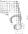
- the machine 500 has a support base 506 having a plurality of mounting holes 508 for anchoring this portion within a protective cabinet (not shown).
- the support base 506 has a mounting platform 510 extending therefrom that includes a bracket 512 for removably positioning the blasting nozzle 502, in particular the tip 514 defining a nozzle exit 516 thereof, in a fixed relationship relative to the part to be modified by the blasting media.
- the machine 500 further includes a handle 518 for operating a clamp 520 that holds the part to be modified, here lower housing portion 106, in relation to the tip 514 of the blasting nozzle 502.
- the mounting platform 510 may include a seat 522 for the Venturi gap section of the lower housing portion 106 to register the part in the proper position relative to the blasting nozzle 502, and may optionally include a cradle 524 for a hose connector or other connector present at the end of the lower housing portion 106 that is most proximate the blasting nozzle 502.
- the blasting media may be propelled from the blasting nozzle 502 into the interior passageway 144 of the lower housing portion 106 for a selected time at a selected pressure.
- the machine 500 is a passive or continuous feed system that itself uses the Venturi principle to propel the blasting media 504 through the nozzle 502.
- the part to be modified is positioned spaced a distance D 2 ( FIG. 11 ) apart from the blasting nozzle 502, in particular the nozzle exit 516.
- This spaced apart distance D 2 should not be so great that the blasting media 504 spreads radially outward and impacts the exterior of the part, in particular the hose connecting feature 118 and modifies this feature.
- D 2 is a pre-selected distance from the blasting nozzle that enables substantially all the blasting media to be received within the converging motive passageway.
- Substantially, as used herein, means less than 5% of the blasting media hits the exterior of the Venturi device during the period of time selected for propelling the blasting media, more preferably less than 3%. If needed, the exterior of the part may be shielded from the blasting media 504 by a shield (not shown) having an opening therethrough positioned to correspond to the motive port's opening.
- the blasting nozzle 502 selected for use with the machine 500 is one having a tip 514 defining a diverging cone 518 as the nozzle exit 516, which diverges toward the part to be modified, i.e., the lower housing section 106 in FIG. 18 .
- This type of blasting nozzle was selected to provide turbulent flow to the blasting media. It was determined that turbulent flow outperformed nozzle's providing laminar flow, which is believed to be linked to the lower housing portion 106 having a converging or diverging passageway receiving the blasting media and because the motive exit and discharge inlet are elliptical or polygonal in shape.
- the machine 500 mounts the lower housing portion 106 in a stationary relationship relative to the blasting nozzle, but in other embodiments, the part may be mounted for rotation of 50 to 500 revolutions during the introduction of the blasting media 504, or more preferable 150 to 400 revolutions, and even more preferably about 250 to 300 revolutions.
- the revolutions are about the central longitudinal axis A (see FIG. 11 ) of passageway 144 through the motive section 180, the Venturi gap 187, and the discharge section 190.
- the revolutions are useful to decrease the time period needed during the introduction of the blasting media because, as discussed above, the motive exit 192 and the discharge inlet 193 are each one of an elliptical, rectilinear, or another polygonal shape (they are not circular).
- the blasting machine may be a closed system having an active source of blasting media.
- there is a source of pressurized blasting media that pushes the blasting media through the nozzle i.e., no Venturi effect is used in this nozzle.
- This method while equally effective, requires period halts in production to replace the source of pressurized blasting media, i.e., when the container runs out. Since a source of pressurized blasting media is used, there is no need for a gap between the part being modified and the blasting nozzle.
- the motive inlet of the part may be directly contacting the nozzle exit 516 or the nozzle exit (tip 514) may be inserted into the motive inlet of the part.
- the controlled time period may be the same, may be increased sequentially, or decreased sequentially.
- the controlled time period for media to pass through the motive port 108 may be greater than the controlled time period for media to pass through the suction port 110 and/or through the bypass port 114 if present, or vice versa. While not illustrated in FIG. 8 , it is possible to propel media into and through the discharge port 112 (and out the motive port 108), as well, in sequence before or after any one of the other phases of propelling media to remove flash.
- connection to the media blasting machine may be through the alignment of separate nozzles with each inlet of the ports present in the Venturi device, the subcomponent thereof, or the check valve.
- the tip of each nozzle may be inserted into each inlet or may be spaced a selected distance from the inlet, or may be connected to the inlet by a length of tubing.
- the rate of material removal (such as the flash) and rate of radius increase (such for corner radius formation) are important in determining the rate of media flow through the nozzle and the controlled time period for the introduction of the media into and through the Venturi device, the subcomponent thereof, or the check valve.
- the rate of media flow is controllable to achieve desired material removal of the flash, and radius increase for the corner radius.
- the pressure of the transport fluid before entry into the nozzle is controllable to change the speed of the media particles.
- the rate of media flow through the nozzle for corner radius formation is greater than the rate of media flow through the nozzle for flash removal.
- the media is introduced into the Venturi device, the subcomponent thereof, or the check valve at a first rate of media flow through the nozzle to remove the flash and then at a second rate of media flow through the nozzle to form a corner radius on an inlet or outlet thereof.
- the second rate may be greater than the first rate, or conversely the first rate may be greater than the second rate.
- the media blasting may also be used to modify the interior surface of the Venturi device, the subcomponent thereof, or the check valve or to form a corner radius on one or both of the interior edge of the motive exit 192 or the interior edge of the discharge inlet 193 at the Venturi gap 187.
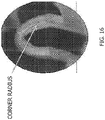
- An example of a corner radius formed by media blasting is shown in the photograph of FIG. 16 and the drawing of FIG. 17 .
- the corner radius 312 is formed after the flash 310 is removed as described above.
- the corner radius 312 is formed in the discharge inlet 193 and extends from the word "begin" to the word "end” in the drawing.
- the corner radius may be in a range of about 0.05 mm to about 1 mm, or more preferably about 0.1 mm to about 0.3 mm or about 0.1 mm to about 0.35 mm. As shown in the cross-section of FIG. 17 , the corner radius has a plurality of regions of curvature R 1 and R 2 that together form the entire corner radius 312. Region of curvature R 2 is positioned further inward relative to the central longitudinal axis A into the diverging discharge passageway. The length of each region of curvature R 1 , R 2 both fall within the mm ranges set forth above, but the length of R 1 is typically smaller than the length of R 2 , while the radius of curvature for R 1 is greater than the radius of R 2 .
- the corner radius 312, in cross-section is generally shaped as the portion of an ellipse, for example the arc between one vertex and one co-vertex of an ellipse, or some portion of that arc.
- Media blasting may also modify the surface finish of the passageway 144 to enhance fluid flow through the Venturi device, the subcomponent thereof, or the check valve.
- the surface roughness average (Ra) of the interior surface of the passageway 144 is in a range of about 0 to about 1000 ⁇ m more preferably about 0 to about 300 ⁇ m.
- the Venturi device, a subcomponent thereof, or the check valve is checked against a preselected performance variable through a test to measure such performance, and if the performance passes, the post-molding manufacturing process is complete. If the performance fails, the process is repeated as many times as necessary to achieve the preselected performance. Photographs of an embodiment of a Venturi device after the flash was removed by media blasting are shown in FIGS. 13 and 15 .
- a lower body housing 106 of the general shape illustrated in FIG. 11 was injection molded from a nylon 6 polymer was subjected to blasting media to remove flash within the motive outlet and the discharge inlet and to modify the discharge inlet to have a corner radius.
- aluminum oxide having a nominal grit of 150 was selected as the blasting media and was propelled into the lower body housing 106 by a supply pressure of about 63 psi (434.37 kPa) for about 6-8 seconds. At these parameters, the flash was quickly removed and the desired corner radius was formed. Thereafter, the lower body housing 106 was cleaned by blowing clean, ionized pressure air through the passageway 144.
- the lower body housing 106 was sealingly connected to an upper housing 104 to form a Venturi device, and tested for its effectiveness at evacuating a vacuum canister, i.e., how quickly it evacuated the canister) and compared to such a Venturi device that was not modified using a post-molding media blasting method.
- the data is presented below in Table 1 for various stages of post-molding media blasting processing of the part. The evacuation time was determined under the same operating conditions for each trial.
- FIG. 9 other methods of removing flash from the interior surface of the Venturi device, the subcomponent thereof, or the check valve are illustrated, which do not form part of the invention but are only shown for illustrative purposes.
- the methods include placing the Venturi device, the subcomponent thereof, or the check valve into a machining fixture to hold the piece during the post-molding process, engaging a machining bit or a thermal bit with a port end of the piece that defines an inlet or an outlet of the piece, and operating the machining bit or thermal bit to remove the flash.
- the piece may optionally be placed into the media blasting machine and processed according to FIG.
- the piece may be processed according to FIG. 10 , where the same or a different machining bit or thermal bit is reintroduced into a port end that defines an inlet or an outlet of the piece, engaged and operated to form a corner radius of the inlet or outlet.
- each of the various embodiments herein is that the noise generated, typically from turbulent flow through the device and the operation of the Venturi portion and/or the check valves, is reduced. This is beneficial to a user who expects a quiet operating system.
Landscapes
- Engineering & Computer Science (AREA)
- Mechanical Engineering (AREA)
- Physics & Mathematics (AREA)
- Thermal Sciences (AREA)
- Jet Pumps And Other Pumps (AREA)
- Processing And Handling Of Plastics And Other Materials For Molding In General (AREA)
- Nozzles (AREA)
Claims (17)
- Procédé de traitement post-moulage d'un dispositif Venturi (100), le procédé comprenant :la fourniture d'un dispositif Venturi (100) moulé présentant un corps (106) définissant un espace de Venturi (187) entre une extrémité de sortie (184) d'un passage moteur convergent (182) et une extrémité d'entrée (186) d'un passage d'évacuation divergent (183),l'extrémité de sortie (184) définissant une sortie motrice (192) présentant une bavure s'étendant radialement vers l'intérieur et l'extrémité d'entrée (186) définissant une entrée d'évacuation (193) présentant une bavure s'étendant radialement vers l'intérieur ;caractérisé parle positionnement du dispositif Venturi (100) moulé avec une extrémité d'entrée (188) du passage moteur convergent (182) ou une extrémité de sortie du passage d'évacuation divergent (183) faisant face à une buse de décapage (502) ; etla propulsion d'un agent de décapage (504) dans une entrée motrice ou une sortie d'évacuation du dispositif Venturi (100) pendant six à huit secondes pour retirer la bavure dans la sortie motrice (192) et dans l'entrée d'évacuation (193) et de modifier la surface intérieure de l'entrée d'évacuation (193) pour former un rayon de coin (312) dans une plage de 0,05 mm à 1 mm.
- Procédé selon la revendication 1, dans lequel l'entrée motrice est de forme circulaire et la sortie motrice est de forme elliptique, le procédé comprenant en outre la rotation du dispositif Venturi (100) autour d'un axe longitudinal central (A) qui s'étend à travers l'entrée motrice, la sortie motrice (192), l'espace de Venturi (187) et l'entrée de d'évacuation (193) durant la propulsion de l'agent de décapage (504).
- Procédé selon la revendication 2, dans lequel la rotation comprend 50 à 500 tours.
- Procédé selon la revendication 1, dans lequel la buse de décapage (502) fait partie d'un système de décapage à alimentation continue, et le positionnement du dispositif Venturi (100) comprend le placement de l'entrée motrice à une distance présélectionnée de la buse de décapage (502), dans lequel pratiquement tout l'agent de décapage (504) est reçu dans le passage moteur convergent (182).
- Procédé selon la revendication 4, dans lequel le système de décapage à alimentation continue comprend un réservoir d'agent de décapage (504) et un collecteur de poussière (528) pour des particules inférieures à un grain 150.
- Procédé selon la revendication 4, dans lequel le système de décapage à alimentation continue comprend en outre un écran protégeant l'extérieur du dispositif Venturi (100) de l'agent de décapage (504).
- Procédé selon la revendication 1, dans lequel la buse de décapage (502) définit une sortie de buse (516) présentant un cône divergent (518), divergeant vers le dispositif Venturi (100).
- Procédé selon la revendication 1, dans lequel la buse de décapage (502) fait partie d'un système de décapage par agent à alimentation fermée, et le positionnement comporte l'insertion d'une sorte de buse (516) de la buse de décapage (502) dans l'entrée motrice du dispositif Venturi (100).
- Procédé selon la revendication 1, comprenant en outre le positionnement d'une buse de décapage secondaire (502) faisant face à un orifice d'aspiration (110) du corps (106), et la propulsion de l'agent de décapage (504) dans le dispositif Venturi (100) à travers l'orifice d'aspiration (110).
- Procédé selon la revendication 9, dans lequel la propulsion de l'agent de décapage (504) se produit d'abord à travers l'entrée motrice et après celle-ci à travers l'orifice d'aspiration (110) ou se produit simultanément à travers l'entrée motrice et l'orifice d'aspiration (110).
- Procédé selon la revendication 1, dans lequel l'agent de décapage comprend un oxyde métallique.
- Procédé selon la revendication 11, dans lequel l'oxyde métallique est de l'oxyde d'aluminium.
- Procédé selon la revendication 1, dans lequel l'agent de décapage (504) comprend un ou plusieurs parmi du verre, du métal, de la céramique, un polymère, une matière végétale, de la glace ou du dioxyde carbone solide.
- Procédé selon la revendication 1, dans lequel le rayon de coin (312) est dans une plage de 0,1 mm à environ 0,35 mm.
- Procédé selon la revendication 1, dans lequel le rayon de coin (312) présente une pluralité de régions de courbure qui forment ensemble le rayon de coin (312) entier, dans lequel une première région (R1) est positionnée le plus près de l'ouverture définissant l'entrée d'évacuation et une deuxième région (R2) est positionnée davantage vers l'intérieur dans le passage d'évacuation divergent (183) par rapport à un axe longitudinal central (A) du corps (106), et une première longueur de la première région (R1) est inférieure à une deuxième longueur de la deuxième région (R2) et le rayon de courbure de la première région (R1) est supérieur au rayon de courbure pour la deuxième région (R2).
- Procédé selon la revendication 15, dans lequel la propulsion de l'agent de décapage (504) comprend un agent de décapage de grain 150 ou de grain inférieur à 150 à une pression de 434,37 kPa.
- Procédé selon la revendication 15, dans lequel la propulsion de l'agent de décapage (504) comprend une buse de décapage (502) présentant un diamètre extérieur de 19,05 mm.
Applications Claiming Priority (2)
| Application Number | Priority Date | Filing Date | Title |
|---|---|---|---|
| US201562183471P | 2015-06-23 | 2015-06-23 | |
| PCT/US2016/038798 WO2016209986A1 (fr) | 2015-06-23 | 2016-06-22 | Procédés de traitement post-moulage d'un dispositif venturi ou d'un clapet de non-retour |
Publications (3)
| Publication Number | Publication Date |
|---|---|
| EP3313613A1 EP3313613A1 (fr) | 2018-05-02 |
| EP3313613A4 EP3313613A4 (fr) | 2019-02-27 |
| EP3313613B1 true EP3313613B1 (fr) | 2022-06-15 |
Family
ID=57585590
Family Applications (1)
| Application Number | Title | Priority Date | Filing Date |
|---|---|---|---|
| EP16815232.0A Active EP3313613B1 (fr) | 2015-06-23 | 2016-06-22 | Procédés de traitement post-moulage d'un dispositif venturi |
Country Status (7)
| Country | Link |
|---|---|
| US (1) | US10239187B2 (fr) |
| EP (1) | EP3313613B1 (fr) |
| JP (1) | JP6636544B2 (fr) |
| KR (1) | KR102400685B1 (fr) |
| CN (1) | CN107635722B (fr) |
| BR (1) | BR112017027242B1 (fr) |
| WO (1) | WO2016209986A1 (fr) |
Families Citing this family (4)
| Publication number | Priority date | Publication date | Assignee | Title |
|---|---|---|---|---|
| US9827963B2 (en) * | 2013-06-11 | 2017-11-28 | Dayco Ip Holdings, Llc | Aspirators for producing vacuum using the Venturi effect |
| WO2018156590A1 (fr) * | 2017-02-21 | 2018-08-30 | Dlhbowles, Inc. | Générateur/amplificateur de vide pour applications gazeuses et procédé de génération d'un servofrein |
| US11408380B2 (en) * | 2020-12-24 | 2022-08-09 | Dayco Ip Holdings, Llc | Devices for producing vacuum using the Venturi effect having a hollow fletch |
| US20230034140A1 (en) * | 2021-07-20 | 2023-02-02 | Harris Research, Inc. | Cleaning machine extractor head |
Citations (1)
| Publication number | Priority date | Publication date | Assignee | Title |
|---|---|---|---|---|
| US5895313A (en) * | 1995-03-29 | 1999-04-20 | Brother Kogyo Kabushiki Kaisha | Method for manufacture of ink jet nozzle |
Family Cites Families (53)
| Publication number | Priority date | Publication date | Assignee | Title |
|---|---|---|---|---|
| US1845969A (en) | 1928-04-02 | 1932-02-16 | Trico Products Corp | Suction augmenting device |
| US2739424A (en) * | 1953-01-05 | 1956-03-27 | Donald E Hilliard | Method of sandblasting |
| US3234932A (en) | 1960-09-19 | 1966-02-15 | Forrest M Bird | Respirator |
| US3754841A (en) | 1971-05-14 | 1973-08-28 | Bendix Corp | Vacuum intensified brake booster system |
| US3914815A (en) * | 1974-09-20 | 1975-10-28 | Fuji Seiki Machine Works | Pipe inside cleaning device |
| DE2717685C3 (de) | 1977-04-21 | 1981-04-02 | Audi Nsu Auto Union Ag, 7107 Neckarsulm | Brennkraftmaschine für Kraftfahrzeuge |
| US4115960A (en) * | 1977-04-28 | 1978-09-26 | Advanced Plastics Machinery Corporation | Method and apparatus for deflashing |
| US4389820A (en) * | 1980-12-29 | 1983-06-28 | Lockheed Corporation | Blasting machine utilizing sublimable particles |
| US4499034A (en) | 1982-09-02 | 1985-02-12 | The United States Of America As Represented By The United States Department Of Energy | Vortex-augmented cooling tower-windmill combination |
| US4554786A (en) | 1982-09-16 | 1985-11-26 | Nissin Kogyo Kabushiki Kaisha | Vacuum source device for vacuum booster for vehicles |
| AU545569B2 (en) | 1982-09-16 | 1985-07-18 | Honda Giken Kogyo Kabushiki Kaisha | Vacuum source device |
| JPS5969265A (ja) | 1982-10-15 | 1984-04-19 | Fuji Seiki Seizosho:Kk | 精密湿式ブラスト用投射材及びその製法 |
| US4519423A (en) * | 1983-07-08 | 1985-05-28 | University Of Southern California | Mixing apparatus using a noncircular jet of small aspect ratio |
| US4946092A (en) * | 1987-11-06 | 1990-08-07 | Nagron Precision Tooling B.V. | Method for arranging a through-channel in a solid body, and the body obtained with this method |
| US5063015A (en) * | 1989-03-13 | 1991-11-05 | Cold Jet, Inc. | Method for deflashing articles |
| US5325638A (en) | 1989-07-07 | 1994-07-05 | Lynn William R | Pliant media blasting device |
| US5108266A (en) | 1991-05-29 | 1992-04-28 | Allied-Signal Inc. | Check valve with aspirating function |
| US5188141A (en) | 1991-12-03 | 1993-02-23 | Siemens Automotive Limited | Vacuum boost valve |
| US5265383A (en) | 1992-11-20 | 1993-11-30 | Church & Dwight Co., Inc. | Fan nozzle |
| US5291916A (en) | 1992-12-28 | 1994-03-08 | Excel Industries, Inc. | Check valve |
| DE4310761C2 (de) | 1993-04-01 | 1995-10-12 | Kayser A Gmbh & Co Kg | Strahlpumpe |
| US5575705A (en) | 1993-08-12 | 1996-11-19 | Church & Dwight Co., Inc. | Slurry blasting process |
| US5366560A (en) | 1993-09-03 | 1994-11-22 | Yelapa Enterprises, Inc. | Cleaning method utilizing sodium bicarbonate particles |
| DE69535095D1 (de) | 1995-02-23 | 2006-08-10 | Ecolab Inc | Vorrichtung zum austeilen von gebrauchsfertiger visköser lösung sowie deren verwendung zum austeilen |
| WO1997049525A1 (fr) | 1996-06-27 | 1997-12-31 | Wizard Technology Limited | Dispositif de projection abrasive |
| US5827114A (en) | 1996-09-25 | 1998-10-27 | Church & Dwight Co., Inc. | Slurry blasting process |
| US5704825A (en) | 1997-01-21 | 1998-01-06 | Lecompte; Gerard J. | Blast nozzle |
| US6035881A (en) | 1997-05-15 | 2000-03-14 | Walter Alfmeier Ag Prazisions-Baugruppenelemente | Checkvalve unit |
| DE19914719C2 (de) * | 1999-03-31 | 2001-05-03 | Siemens Ag | Vorrichtung zum hydroerosiven Runden von Einlaufkanten der Spritzlochkanäle in einem Düsenkörper |
| JP2001295800A (ja) | 1999-12-08 | 2001-10-26 | Myotoku Ltd | エゼクタ式真空発生器 |
| US6350185B1 (en) * | 2000-02-09 | 2002-02-26 | Space Systems/Loral, Inc. | Grit blast nozzle for surface preparation of tube |
| US20020072306A1 (en) * | 2000-06-14 | 2002-06-13 | Carpenter Steven J. | Chamber-type vibratory finisher with blasting nozzle |
| GB2367777A (en) | 2000-10-10 | 2002-04-17 | Peter Reynolds | Blast processing using turbine blowers |
| GB0200372D0 (en) | 2002-01-08 | 2002-02-20 | Aquablast Ltd | Removing surface coatings and contamination |
| JP2003285268A (ja) * | 2002-03-27 | 2003-10-07 | Sugino Mach Ltd | バリ取りとr面取りの加工方法 |
| JP3681714B2 (ja) * | 2002-06-18 | 2005-08-10 | 株式会社不二精機製造所 | 部材内部の長孔交差部のブラスト加工方法 |
| DE102004002421A1 (de) * | 2004-01-16 | 2005-08-18 | Atotech Deutschland Gmbh | Düsenanordnung |
| US20060016477A1 (en) | 2004-07-23 | 2006-01-26 | Algis Zaparackas | Vacuum enhancing check valve |
| SE528482C2 (sv) | 2005-05-25 | 2006-11-28 | Gm Global Tech Operations Inc | Bromsservosystem i en förbränningsmotor av typ Otto |
| WO2007117529A1 (fr) | 2006-04-05 | 2007-10-18 | Continental Automotive Systems Us, Inc. | Procede de fabrication d'un tube de venturi pour un systeme de carburant |
| KR100767486B1 (ko) | 2006-06-26 | 2007-10-17 | 현대자동차주식회사 | 차량용 브레이크 부압 증폭기 |
| JP2008128150A (ja) | 2006-11-23 | 2008-06-05 | Aisan Ind Co Ltd | エゼクタおよびそれを用いたブレーキブースタ用負圧供給装置 |
| CN100999126A (zh) * | 2007-01-08 | 2007-07-18 | 廖茂钧 | 喷砂机喷嘴的成型方法 |
| US8061296B1 (en) * | 2009-03-05 | 2011-11-22 | Tom Batur | Pipe treatment apparatus |
| US20110186151A1 (en) * | 2010-02-04 | 2011-08-04 | Bernard Joseph Sparazynski | Check valve |
| US8925520B2 (en) | 2010-03-10 | 2015-01-06 | Ford Global Technologies, Llc | Intake system including vacuum aspirator |
| JP5606824B2 (ja) * | 2010-08-18 | 2014-10-15 | 株式会社不二製作所 | 金型の表面処理方法及び前記方法で表面処理された金型 |
| US10337628B2 (en) | 2012-02-20 | 2019-07-02 | Nyloncraft Incorporated | High mass flow check valve aspirator |
| US9022007B2 (en) | 2012-03-09 | 2015-05-05 | Ford Global Technologies, Llc | Throttle valve system for an engine |
| US8783231B2 (en) | 2012-03-12 | 2014-07-22 | Ford Global Technologies, Llc | Venturi for vapor purge |
| DE102012211000A1 (de) * | 2012-06-27 | 2014-01-02 | Robert Bosch Gmbh | Verfahren zum hydroerosiven Verrunden von Bohrungen |
| US9827963B2 (en) * | 2013-06-11 | 2017-11-28 | Dayco Ip Holdings, Llc | Aspirators for producing vacuum using the Venturi effect |
| CN103659183B (zh) * | 2013-12-05 | 2017-03-01 | 浙江波威钢构有限公司 | 一种防腐大小头管件的制作方法 |
-
2016
- 2016-06-22 KR KR1020177035322A patent/KR102400685B1/ko active IP Right Grant
- 2016-06-22 CN CN201680032692.5A patent/CN107635722B/zh active Active
- 2016-06-22 US US15/189,922 patent/US10239187B2/en active Active
- 2016-06-22 BR BR112017027242-3A patent/BR112017027242B1/pt active IP Right Grant
- 2016-06-22 JP JP2017564624A patent/JP6636544B2/ja active Active
- 2016-06-22 EP EP16815232.0A patent/EP3313613B1/fr active Active
- 2016-06-22 WO PCT/US2016/038798 patent/WO2016209986A1/fr unknown
Patent Citations (1)
| Publication number | Priority date | Publication date | Assignee | Title |
|---|---|---|---|---|
| US5895313A (en) * | 1995-03-29 | 1999-04-20 | Brother Kogyo Kabushiki Kaisha | Method for manufacture of ink jet nozzle |
Also Published As
| Publication number | Publication date |
|---|---|
| BR112017027242B1 (pt) | 2021-12-07 |
| KR102400685B1 (ko) | 2022-05-20 |
| JP2018521864A (ja) | 2018-08-09 |
| JP6636544B2 (ja) | 2020-01-29 |
| CN107635722A (zh) | 2018-01-26 |
| EP3313613A1 (fr) | 2018-05-02 |
| KR20180019539A (ko) | 2018-02-26 |
| EP3313613A4 (fr) | 2019-02-27 |
| BR112017027242A2 (pt) | 2018-08-28 |
| US10239187B2 (en) | 2019-03-26 |
| CN107635722B (zh) | 2021-11-05 |
| WO2016209986A1 (fr) | 2016-12-29 |
| US20160375548A1 (en) | 2016-12-29 |
Similar Documents
| Publication | Publication Date | Title |
|---|---|---|
| EP3313613B1 (fr) | Procédés de traitement post-moulage d'un dispositif venturi | |
| US10724550B2 (en) | Venturi devices with dual Venturi flow paths | |
| EP3784939B1 (fr) | Insert de clapet d'anti-retour délimitant une position ouverte, et clapets anti-retour équipés de celui-ci | |
| EP3505801B1 (fr) | Atténuation du bruit dans une unité de soupape anti-retour ou un appareil de production de vide | |
| EP3126201B1 (fr) | Clapet anti-retour de dérivation et dispositifs venturi doté de celui-ci | |
| CN107429709B (zh) | 用于使用文丘里效应产生真空的装置 | |
| CN109715998B (zh) | 用于产生真空的文丘里装置及其系统 | |
| US20140024295A1 (en) | Fluid jet receiving receptacles and related fluid jet cutting systems and methods | |
| JP5817043B2 (ja) | ノンコンタクト搬送パッド | |
| EP3240653B1 (fr) | Dispositif d'extraction de poussiere | |
| CN209919098U (zh) | 除尘装置和激光切割设备 | |
| CN108890125B (zh) | 一种激光头除尘装置、激光器 | |
| JP2942168B2 (ja) | ブラスト加工における加工パターンの拡大方法及び装置 | |
| KR101611518B1 (ko) | 배출가속기 및 이를 구비한 로드 포트 | |
| EP3478546B1 (fr) | Clapet de dérivation dans un appareil de production de vide | |
| JP6427445B2 (ja) | 真空保持装置及びこれを用いた半導体ウェーハ研磨装置 | |
| JP2020075303A (ja) | ノズルおよびブラスト装置 | |
| JP2005279786A (ja) | 線材表面研削装置 | |
| JP2024501968A (ja) | 中実フレッチを具備し、ベンチュリ効果を利用して真空を生成するための装置 | |
| TWI526280B (zh) | And a bead processing apparatus for a bead processing chamber in which the attachment of the sprayed material and the dust to the inner wall is suppressed | |
| JP2024501967A (ja) | 中空フレッチを有するベンチュリ効果を利用して真空を発生させる装置 | |
| JP2023062801A (ja) | 除塵装置 | |
| JP2022129669A (ja) | ブラストガン | |
| KR20200043023A (ko) | 구조물 내부 폴리싱 장치 | |
| JP2004025108A (ja) | 粉体噴射装置 |
Legal Events
| Date | Code | Title | Description |
|---|---|---|---|
| STAA | Information on the status of an ep patent application or granted ep patent |
Free format text: STATUS: THE INTERNATIONAL PUBLICATION HAS BEEN MADE |
|
| PUAI | Public reference made under article 153(3) epc to a published international application that has entered the european phase |
Free format text: ORIGINAL CODE: 0009012 |
|
| STAA | Information on the status of an ep patent application or granted ep patent |
Free format text: STATUS: REQUEST FOR EXAMINATION WAS MADE |
|
| 17P | Request for examination filed |
Effective date: 20180122 |
|
| AK | Designated contracting states |
Kind code of ref document: A1 Designated state(s): AL AT BE BG CH CY CZ DE DK EE ES FI FR GB GR HR HU IE IS IT LI LT LU LV MC MK MT NL NO PL PT RO RS SE SI SK SM TR |
|
| AX | Request for extension of the european patent |
Extension state: BA ME |
|
| DAV | Request for validation of the european patent (deleted) | ||
| DAX | Request for extension of the european patent (deleted) | ||
| A4 | Supplementary search report drawn up and despatched |
Effective date: 20190124 |
|
| RIC1 | Information provided on ipc code assigned before grant |
Ipc: B29C 37/02 20060101ALI20190118BHEP Ipc: B24C 3/16 20060101ALI20190118BHEP Ipc: B29C 45/26 20060101ALI20190118BHEP Ipc: B29C 49/50 20060101ALI20190118BHEP Ipc: B24C 9/00 20060101ALI20190118BHEP Ipc: B24C 3/32 20060101AFI20190118BHEP |
|
| RIC1 | Information provided on ipc code assigned before grant |
Ipc: B29L 31/00 20060101ALN20211019BHEP Ipc: B29C 37/02 20060101ALI20211019BHEP Ipc: B24C 11/00 20060101ALI20211019BHEP Ipc: B24C 3/32 20060101AFI20211019BHEP |
|
| RIC1 | Information provided on ipc code assigned before grant |
Ipc: B29L 31/00 20060101ALN20211025BHEP Ipc: B29C 37/02 20060101ALI20211025BHEP Ipc: B24C 11/00 20060101ALI20211025BHEP Ipc: B24C 3/32 20060101AFI20211025BHEP |
|
| RIC1 | Information provided on ipc code assigned before grant |
Ipc: B29L 31/00 20060101ALN20211124BHEP Ipc: B29C 37/02 20060101ALI20211124BHEP Ipc: B24C 11/00 20060101ALI20211124BHEP Ipc: B24C 3/32 20060101AFI20211124BHEP |
|
| GRAP | Despatch of communication of intention to grant a patent |
Free format text: ORIGINAL CODE: EPIDOSNIGR1 |
|
| STAA | Information on the status of an ep patent application or granted ep patent |
Free format text: STATUS: GRANT OF PATENT IS INTENDED |
|
| INTG | Intention to grant announced |
Effective date: 20220110 |
|
| GRAS | Grant fee paid |
Free format text: ORIGINAL CODE: EPIDOSNIGR3 |
|
| RAP3 | Party data changed (applicant data changed or rights of an application transferred) |
Owner name: DAYCO IP HOLDINGS, LLC |
|
| GRAA | (expected) grant |
Free format text: ORIGINAL CODE: 0009210 |
|
| STAA | Information on the status of an ep patent application or granted ep patent |
Free format text: STATUS: THE PATENT HAS BEEN GRANTED |
|
| AK | Designated contracting states |
Kind code of ref document: B1 Designated state(s): AL AT BE BG CH CY CZ DE DK EE ES FI FR GB GR HR HU IE IS IT LI LT LU LV MC MK MT NL NO PL PT RO RS SE SI SK SM TR |
|
| REG | Reference to a national code |
Ref country code: CH Ref legal event code: EP Ref country code: GB Ref legal event code: FG4D |
|
| REG | Reference to a national code |
Ref country code: IE Ref legal event code: FG4D |
|
| REG | Reference to a national code |
Ref country code: DE Ref legal event code: R096 Ref document number: 602016072879 Country of ref document: DE |
|
| REG | Reference to a national code |
Ref country code: AT Ref legal event code: REF Ref document number: 1498066 Country of ref document: AT Kind code of ref document: T Effective date: 20220715 |
|
| REG | Reference to a national code |
Ref country code: LT Ref legal event code: MG9D |
|
| REG | Reference to a national code |
Ref country code: NL Ref legal event code: MP Effective date: 20220615 |
|
| PG25 | Lapsed in a contracting state [announced via postgrant information from national office to epo] |
Ref country code: SE Free format text: LAPSE BECAUSE OF FAILURE TO SUBMIT A TRANSLATION OF THE DESCRIPTION OR TO PAY THE FEE WITHIN THE PRESCRIBED TIME-LIMIT Effective date: 20220615 Ref country code: NO Free format text: LAPSE BECAUSE OF FAILURE TO SUBMIT A TRANSLATION OF THE DESCRIPTION OR TO PAY THE FEE WITHIN THE PRESCRIBED TIME-LIMIT Effective date: 20220915 Ref country code: LT Free format text: LAPSE BECAUSE OF FAILURE TO SUBMIT A TRANSLATION OF THE DESCRIPTION OR TO PAY THE FEE WITHIN THE PRESCRIBED TIME-LIMIT Effective date: 20220615 Ref country code: HR Free format text: LAPSE BECAUSE OF FAILURE TO SUBMIT A TRANSLATION OF THE DESCRIPTION OR TO PAY THE FEE WITHIN THE PRESCRIBED TIME-LIMIT Effective date: 20220615 Ref country code: GR Free format text: LAPSE BECAUSE OF FAILURE TO SUBMIT A TRANSLATION OF THE DESCRIPTION OR TO PAY THE FEE WITHIN THE PRESCRIBED TIME-LIMIT Effective date: 20220916 Ref country code: FI Free format text: LAPSE BECAUSE OF FAILURE TO SUBMIT A TRANSLATION OF THE DESCRIPTION OR TO PAY THE FEE WITHIN THE PRESCRIBED TIME-LIMIT Effective date: 20220615 Ref country code: BG Free format text: LAPSE BECAUSE OF FAILURE TO SUBMIT A TRANSLATION OF THE DESCRIPTION OR TO PAY THE FEE WITHIN THE PRESCRIBED TIME-LIMIT Effective date: 20220915 |
|
| REG | Reference to a national code |
Ref country code: AT Ref legal event code: MK05 Ref document number: 1498066 Country of ref document: AT Kind code of ref document: T Effective date: 20220615 |
|
| PG25 | Lapsed in a contracting state [announced via postgrant information from national office to epo] |
Ref country code: RS Free format text: LAPSE BECAUSE OF FAILURE TO SUBMIT A TRANSLATION OF THE DESCRIPTION OR TO PAY THE FEE WITHIN THE PRESCRIBED TIME-LIMIT Effective date: 20220615 Ref country code: LV Free format text: LAPSE BECAUSE OF FAILURE TO SUBMIT A TRANSLATION OF THE DESCRIPTION OR TO PAY THE FEE WITHIN THE PRESCRIBED TIME-LIMIT Effective date: 20220615 |
|
| PG25 | Lapsed in a contracting state [announced via postgrant information from national office to epo] |
Ref country code: NL Free format text: LAPSE BECAUSE OF FAILURE TO SUBMIT A TRANSLATION OF THE DESCRIPTION OR TO PAY THE FEE WITHIN THE PRESCRIBED TIME-LIMIT Effective date: 20220615 |
|
| PG25 | Lapsed in a contracting state [announced via postgrant information from national office to epo] |
Ref country code: SM Free format text: LAPSE BECAUSE OF FAILURE TO SUBMIT A TRANSLATION OF THE DESCRIPTION OR TO PAY THE FEE WITHIN THE PRESCRIBED TIME-LIMIT Effective date: 20220615 Ref country code: SK Free format text: LAPSE BECAUSE OF FAILURE TO SUBMIT A TRANSLATION OF THE DESCRIPTION OR TO PAY THE FEE WITHIN THE PRESCRIBED TIME-LIMIT Effective date: 20220615 Ref country code: RO Free format text: LAPSE BECAUSE OF FAILURE TO SUBMIT A TRANSLATION OF THE DESCRIPTION OR TO PAY THE FEE WITHIN THE PRESCRIBED TIME-LIMIT Effective date: 20220615 Ref country code: PT Free format text: LAPSE BECAUSE OF FAILURE TO SUBMIT A TRANSLATION OF THE DESCRIPTION OR TO PAY THE FEE WITHIN THE PRESCRIBED TIME-LIMIT Effective date: 20221017 Ref country code: ES Free format text: LAPSE BECAUSE OF FAILURE TO SUBMIT A TRANSLATION OF THE DESCRIPTION OR TO PAY THE FEE WITHIN THE PRESCRIBED TIME-LIMIT Effective date: 20220615 Ref country code: EE Free format text: LAPSE BECAUSE OF FAILURE TO SUBMIT A TRANSLATION OF THE DESCRIPTION OR TO PAY THE FEE WITHIN THE PRESCRIBED TIME-LIMIT Effective date: 20220615 Ref country code: CZ Free format text: LAPSE BECAUSE OF FAILURE TO SUBMIT A TRANSLATION OF THE DESCRIPTION OR TO PAY THE FEE WITHIN THE PRESCRIBED TIME-LIMIT Effective date: 20220615 Ref country code: AT Free format text: LAPSE BECAUSE OF FAILURE TO SUBMIT A TRANSLATION OF THE DESCRIPTION OR TO PAY THE FEE WITHIN THE PRESCRIBED TIME-LIMIT Effective date: 20220615 |
|
| REG | Reference to a national code |
Ref country code: CH Ref legal event code: PL |
|
| REG | Reference to a national code |
Ref country code: BE Ref legal event code: MM Effective date: 20220630 |
|
| PG25 | Lapsed in a contracting state [announced via postgrant information from national office to epo] |
Ref country code: PL Free format text: LAPSE BECAUSE OF FAILURE TO SUBMIT A TRANSLATION OF THE DESCRIPTION OR TO PAY THE FEE WITHIN THE PRESCRIBED TIME-LIMIT Effective date: 20220615 Ref country code: IS Free format text: LAPSE BECAUSE OF FAILURE TO SUBMIT A TRANSLATION OF THE DESCRIPTION OR TO PAY THE FEE WITHIN THE PRESCRIBED TIME-LIMIT Effective date: 20221015 |
|
| REG | Reference to a national code |
Ref country code: DE Ref legal event code: R097 Ref document number: 602016072879 Country of ref document: DE |
|
| PG25 | Lapsed in a contracting state [announced via postgrant information from national office to epo] |
Ref country code: MC Free format text: LAPSE BECAUSE OF FAILURE TO SUBMIT A TRANSLATION OF THE DESCRIPTION OR TO PAY THE FEE WITHIN THE PRESCRIBED TIME-LIMIT Effective date: 20220615 Ref country code: AL Free format text: LAPSE BECAUSE OF FAILURE TO SUBMIT A TRANSLATION OF THE DESCRIPTION OR TO PAY THE FEE WITHIN THE PRESCRIBED TIME-LIMIT Effective date: 20220615 |
|
| PLBE | No opposition filed within time limit |
Free format text: ORIGINAL CODE: 0009261 |
|
| STAA | Information on the status of an ep patent application or granted ep patent |
Free format text: STATUS: NO OPPOSITION FILED WITHIN TIME LIMIT |
|
| PG25 | Lapsed in a contracting state [announced via postgrant information from national office to epo] |
Ref country code: LU Free format text: LAPSE BECAUSE OF NON-PAYMENT OF DUE FEES Effective date: 20220622 Ref country code: LI Free format text: LAPSE BECAUSE OF NON-PAYMENT OF DUE FEES Effective date: 20220630 Ref country code: IE Free format text: LAPSE BECAUSE OF NON-PAYMENT OF DUE FEES Effective date: 20220622 Ref country code: DK Free format text: LAPSE BECAUSE OF FAILURE TO SUBMIT A TRANSLATION OF THE DESCRIPTION OR TO PAY THE FEE WITHIN THE PRESCRIBED TIME-LIMIT Effective date: 20220615 Ref country code: CH Free format text: LAPSE BECAUSE OF NON-PAYMENT OF DUE FEES Effective date: 20220630 |
|
| 26N | No opposition filed |
Effective date: 20230316 |
|
| GBPC | Gb: european patent ceased through non-payment of renewal fee |
Effective date: 20220915 |
|
| PG25 | Lapsed in a contracting state [announced via postgrant information from national office to epo] |
Ref country code: SI Free format text: LAPSE BECAUSE OF FAILURE TO SUBMIT A TRANSLATION OF THE DESCRIPTION OR TO PAY THE FEE WITHIN THE PRESCRIBED TIME-LIMIT Effective date: 20220615 Ref country code: BE Free format text: LAPSE BECAUSE OF NON-PAYMENT OF DUE FEES Effective date: 20220630 |
|
| P01 | Opt-out of the competence of the unified patent court (upc) registered |
Effective date: 20230522 |
|
| PG25 | Lapsed in a contracting state [announced via postgrant information from national office to epo] |
Ref country code: FR Free format text: LAPSE BECAUSE OF NON-PAYMENT OF DUE FEES Effective date: 20220815 |
|
| PGFP | Annual fee paid to national office [announced via postgrant information from national office to epo] |
Ref country code: DE Payment date: 20230628 Year of fee payment: 8 |
|
| PG25 | Lapsed in a contracting state [announced via postgrant information from national office to epo] |
Ref country code: GB Free format text: LAPSE BECAUSE OF NON-PAYMENT OF DUE FEES Effective date: 20220915 |
|
| PG25 | Lapsed in a contracting state [announced via postgrant information from national office to epo] |
Ref country code: IT Free format text: LAPSE BECAUSE OF FAILURE TO SUBMIT A TRANSLATION OF THE DESCRIPTION OR TO PAY THE FEE WITHIN THE PRESCRIBED TIME-LIMIT Effective date: 20220615 |
|
| PG25 | Lapsed in a contracting state [announced via postgrant information from national office to epo] |
Ref country code: HU Free format text: LAPSE BECAUSE OF FAILURE TO SUBMIT A TRANSLATION OF THE DESCRIPTION OR TO PAY THE FEE WITHIN THE PRESCRIBED TIME-LIMIT; INVALID AB INITIO Effective date: 20160622 |
|
| PG25 | Lapsed in a contracting state [announced via postgrant information from national office to epo] |
Ref country code: MK Free format text: LAPSE BECAUSE OF FAILURE TO SUBMIT A TRANSLATION OF THE DESCRIPTION OR TO PAY THE FEE WITHIN THE PRESCRIBED TIME-LIMIT Effective date: 20220615 Ref country code: CY Free format text: LAPSE BECAUSE OF FAILURE TO SUBMIT A TRANSLATION OF THE DESCRIPTION OR TO PAY THE FEE WITHIN THE PRESCRIBED TIME-LIMIT Effective date: 20220615 |