EP3505801B1 - Atténuation du bruit dans une unité de soupape anti-retour ou un appareil de production de vide - Google Patents
Atténuation du bruit dans une unité de soupape anti-retour ou un appareil de production de vide Download PDFInfo
- Publication number
- EP3505801B1 EP3505801B1 EP19157773.3A EP19157773A EP3505801B1 EP 3505801 B1 EP3505801 B1 EP 3505801B1 EP 19157773 A EP19157773 A EP 19157773A EP 3505801 B1 EP3505801 B1 EP 3505801B1
- Authority
- EP
- European Patent Office
- Prior art keywords
- sound attenuating
- canister
- check valve
- venturi
- port
- Prior art date
- Legal status (The legal status is an assumption and is not a legal conclusion. Google has not performed a legal analysis and makes no representation as to the accuracy of the status listed.)
- Active
Links
- 239000012530 fluid Substances 0.000 claims description 29
- 238000004891 communication Methods 0.000 claims description 14
- 238000011144 upstream manufacturing Methods 0.000 claims description 7
- 238000002485 combustion reaction Methods 0.000 claims description 6
- 239000000463 material Substances 0.000 claims description 6
- 230000009977 dual effect Effects 0.000 claims description 2
- 239000003570 air Substances 0.000 description 23
- 230000000712 assembly Effects 0.000 description 8
- 238000000429 assembly Methods 0.000 description 8
- 238000007789 sealing Methods 0.000 description 7
- 230000008901 benefit Effects 0.000 description 4
- 239000011148 porous material Substances 0.000 description 4
- 230000000087 stabilizing effect Effects 0.000 description 4
- 230000000694 effects Effects 0.000 description 3
- 239000000446 fuel Substances 0.000 description 3
- 239000012080 ambient air Substances 0.000 description 1
- 230000002238 attenuated effect Effects 0.000 description 1
- 230000009286 beneficial effect Effects 0.000 description 1
- 230000005540 biological transmission Effects 0.000 description 1
- 239000000919 ceramic Substances 0.000 description 1
- 239000000084 colloidal system Substances 0.000 description 1
- 238000007796 conventional method Methods 0.000 description 1
- 235000012489 doughnuts Nutrition 0.000 description 1
- 239000000835 fiber Substances 0.000 description 1
- 239000007789 gas Substances 0.000 description 1
- 239000011521 glass Substances 0.000 description 1
- 238000010438 heat treatment Methods 0.000 description 1
- 230000001939 inductive effect Effects 0.000 description 1
- 230000002452 interceptive effect Effects 0.000 description 1
- 239000007788 liquid Substances 0.000 description 1
- 230000013011 mating Effects 0.000 description 1
- 239000002184 metal Substances 0.000 description 1
- 229910052751 metal Inorganic materials 0.000 description 1
- 150000002739 metals Chemical class 0.000 description 1
- 238000012986 modification Methods 0.000 description 1
- 230000004048 modification Effects 0.000 description 1
- 230000010355 oscillation Effects 0.000 description 1
- 239000002245 particle Substances 0.000 description 1
- 239000004033 plastic Substances 0.000 description 1
- 229920003023 plastic Polymers 0.000 description 1
- 238000010926 purge Methods 0.000 description 1
- 239000007787 solid Substances 0.000 description 1
- 229910001220 stainless steel Inorganic materials 0.000 description 1
- 230000001502 supplementing effect Effects 0.000 description 1
- 239000000725 suspension Substances 0.000 description 1
- 230000001052 transient effect Effects 0.000 description 1
- 238000013519 translation Methods 0.000 description 1
- 238000003466 welding Methods 0.000 description 1
- 238000004804 winding Methods 0.000 description 1
Images


Classifications
-
- F—MECHANICAL ENGINEERING; LIGHTING; HEATING; WEAPONS; BLASTING
- F16—ENGINEERING ELEMENTS AND UNITS; GENERAL MEASURES FOR PRODUCING AND MAINTAINING EFFECTIVE FUNCTIONING OF MACHINES OR INSTALLATIONS; THERMAL INSULATION IN GENERAL
- F16K—VALVES; TAPS; COCKS; ACTUATING-FLOATS; DEVICES FOR VENTING OR AERATING
- F16K15/00—Check valves
-
- F—MECHANICAL ENGINEERING; LIGHTING; HEATING; WEAPONS; BLASTING
- F16—ENGINEERING ELEMENTS AND UNITS; GENERAL MEASURES FOR PRODUCING AND MAINTAINING EFFECTIVE FUNCTIONING OF MACHINES OR INSTALLATIONS; THERMAL INSULATION IN GENERAL
- F16K—VALVES; TAPS; COCKS; ACTUATING-FLOATS; DEVICES FOR VENTING OR AERATING
- F16K47/00—Means in valves for absorbing fluid energy
- F16K47/08—Means in valves for absorbing fluid energy for decreasing pressure or noise level and having a throttling member separate from the closure member, e.g. screens, slots, labyrinths
-
- B—PERFORMING OPERATIONS; TRANSPORTING
- B60—VEHICLES IN GENERAL
- B60T—VEHICLE BRAKE CONTROL SYSTEMS OR PARTS THEREOF; BRAKE CONTROL SYSTEMS OR PARTS THEREOF, IN GENERAL; ARRANGEMENT OF BRAKING ELEMENTS ON VEHICLES IN GENERAL; PORTABLE DEVICES FOR PREVENTING UNWANTED MOVEMENT OF VEHICLES; VEHICLE MODIFICATIONS TO FACILITATE COOLING OF BRAKES
- B60T17/00—Component parts, details, or accessories of power brake systems not covered by groups B60T8/00, B60T13/00 or B60T15/00, or presenting other characteristic features
- B60T17/002—Air treatment devices
- B60T17/008—Silencer devices
-
- B—PERFORMING OPERATIONS; TRANSPORTING
- B60—VEHICLES IN GENERAL
- B60T—VEHICLE BRAKE CONTROL SYSTEMS OR PARTS THEREOF; BRAKE CONTROL SYSTEMS OR PARTS THEREOF, IN GENERAL; ARRANGEMENT OF BRAKING ELEMENTS ON VEHICLES IN GENERAL; PORTABLE DEVICES FOR PREVENTING UNWANTED MOVEMENT OF VEHICLES; VEHICLE MODIFICATIONS TO FACILITATE COOLING OF BRAKES
- B60T17/00—Component parts, details, or accessories of power brake systems not covered by groups B60T8/00, B60T13/00 or B60T15/00, or presenting other characteristic features
- B60T17/04—Arrangements of piping, valves in the piping, e.g. cut-off valves, couplings or air hoses
-
- F—MECHANICAL ENGINEERING; LIGHTING; HEATING; WEAPONS; BLASTING
- F02—COMBUSTION ENGINES; HOT-GAS OR COMBUSTION-PRODUCT ENGINE PLANTS
- F02B—INTERNAL-COMBUSTION PISTON ENGINES; COMBUSTION ENGINES IN GENERAL
- F02B27/00—Use of kinetic or wave energy of charge in induction systems, or of combustion residues in exhaust systems, for improving quantity of charge or for increasing removal of combustion residues
- F02B27/003—Use of kinetic or wave energy of charge in induction systems, or of combustion residues in exhaust systems, for improving quantity of charge or for increasing removal of combustion residues using check valves
-
- F—MECHANICAL ENGINEERING; LIGHTING; HEATING; WEAPONS; BLASTING
- F02—COMBUSTION ENGINES; HOT-GAS OR COMBUSTION-PRODUCT ENGINE PLANTS
- F02M—SUPPLYING COMBUSTION ENGINES IN GENERAL WITH COMBUSTIBLE MIXTURES OR CONSTITUENTS THEREOF
- F02M35/00—Combustion-air cleaners, air intakes, intake silencers, or induction systems specially adapted for, or arranged on, internal-combustion engines
- F02M35/12—Intake silencers ; Sound modulation, transmission or amplification
- F02M35/1244—Intake silencers ; Sound modulation, transmission or amplification using interference; Masking or reflecting sound
-
- F—MECHANICAL ENGINEERING; LIGHTING; HEATING; WEAPONS; BLASTING
- F02—COMBUSTION ENGINES; HOT-GAS OR COMBUSTION-PRODUCT ENGINE PLANTS
- F02M—SUPPLYING COMBUSTION ENGINES IN GENERAL WITH COMBUSTIBLE MIXTURES OR CONSTITUENTS THEREOF
- F02M35/00—Combustion-air cleaners, air intakes, intake silencers, or induction systems specially adapted for, or arranged on, internal-combustion engines
- F02M35/12—Intake silencers ; Sound modulation, transmission or amplification
- F02M35/1272—Intake silencers ; Sound modulation, transmission or amplification using absorbing, damping, insulating or reflecting materials, e.g. porous foams, fibres, rubbers, fabrics, coatings or membranes
-
- F—MECHANICAL ENGINEERING; LIGHTING; HEATING; WEAPONS; BLASTING
- F04—POSITIVE - DISPLACEMENT MACHINES FOR LIQUIDS; PUMPS FOR LIQUIDS OR ELASTIC FLUIDS
- F04F—PUMPING OF FLUID BY DIRECT CONTACT OF ANOTHER FLUID OR BY USING INERTIA OF FLUID TO BE PUMPED; SIPHONS
- F04F5/00—Jet pumps, i.e. devices in which flow is induced by pressure drop caused by velocity of another fluid flow
- F04F5/14—Jet pumps, i.e. devices in which flow is induced by pressure drop caused by velocity of another fluid flow the inducing fluid being elastic fluid
- F04F5/16—Jet pumps, i.e. devices in which flow is induced by pressure drop caused by velocity of another fluid flow the inducing fluid being elastic fluid displacing elastic fluids
- F04F5/20—Jet pumps, i.e. devices in which flow is induced by pressure drop caused by velocity of another fluid flow the inducing fluid being elastic fluid displacing elastic fluids for evacuating
-
- F—MECHANICAL ENGINEERING; LIGHTING; HEATING; WEAPONS; BLASTING
- F16—ENGINEERING ELEMENTS AND UNITS; GENERAL MEASURES FOR PRODUCING AND MAINTAINING EFFECTIVE FUNCTIONING OF MACHINES OR INSTALLATIONS; THERMAL INSULATION IN GENERAL
- F16K—VALVES; TAPS; COCKS; ACTUATING-FLOATS; DEVICES FOR VENTING OR AERATING
- F16K15/00—Check valves
- F16K15/02—Check valves with guided rigid valve members
- F16K15/021—Check valves with guided rigid valve members the valve member being a movable body around which the medium flows when the valve is open
- F16K15/023—Check valves with guided rigid valve members the valve member being a movable body around which the medium flows when the valve is open the valve member consisting only of a predominantly disc-shaped flat element
-
- F—MECHANICAL ENGINEERING; LIGHTING; HEATING; WEAPONS; BLASTING
- F16—ENGINEERING ELEMENTS AND UNITS; GENERAL MEASURES FOR PRODUCING AND MAINTAINING EFFECTIVE FUNCTIONING OF MACHINES OR INSTALLATIONS; THERMAL INSULATION IN GENERAL
- F16K—VALVES; TAPS; COCKS; ACTUATING-FLOATS; DEVICES FOR VENTING OR AERATING
- F16K27/00—Construction of housing; Use of materials therefor
- F16K27/02—Construction of housing; Use of materials therefor of lift valves
- F16K27/0209—Check valves or pivoted valves
-
- F—MECHANICAL ENGINEERING; LIGHTING; HEATING; WEAPONS; BLASTING
- F16—ENGINEERING ELEMENTS AND UNITS; GENERAL MEASURES FOR PRODUCING AND MAINTAINING EFFECTIVE FUNCTIONING OF MACHINES OR INSTALLATIONS; THERMAL INSULATION IN GENERAL
- F16K—VALVES; TAPS; COCKS; ACTUATING-FLOATS; DEVICES FOR VENTING OR AERATING
- F16K47/00—Means in valves for absorbing fluid energy
- F16K47/08—Means in valves for absorbing fluid energy for decreasing pressure or noise level and having a throttling member separate from the closure member, e.g. screens, slots, labyrinths
- F16K47/14—Means in valves for absorbing fluid energy for decreasing pressure or noise level and having a throttling member separate from the closure member, e.g. screens, slots, labyrinths the throttling member being a perforated membrane
-
- F—MECHANICAL ENGINEERING; LIGHTING; HEATING; WEAPONS; BLASTING
- F02—COMBUSTION ENGINES; HOT-GAS OR COMBUSTION-PRODUCT ENGINE PLANTS
- F02M—SUPPLYING COMBUSTION ENGINES IN GENERAL WITH COMBUSTIBLE MIXTURES OR CONSTITUENTS THEREOF
- F02M35/00—Combustion-air cleaners, air intakes, intake silencers, or induction systems specially adapted for, or arranged on, internal-combustion engines
- F02M35/10—Air intakes; Induction systems
- F02M35/10209—Fluid connections to the air intake system; their arrangement of pipes, valves or the like
- F02M35/10229—Fluid connections to the air intake system; their arrangement of pipes, valves or the like the intake system acting as a vacuum or overpressure source for auxiliary devices, e.g. brake systems; Vacuum chambers
-
- Y—GENERAL TAGGING OF NEW TECHNOLOGICAL DEVELOPMENTS; GENERAL TAGGING OF CROSS-SECTIONAL TECHNOLOGIES SPANNING OVER SEVERAL SECTIONS OF THE IPC; TECHNICAL SUBJECTS COVERED BY FORMER USPC CROSS-REFERENCE ART COLLECTIONS [XRACs] AND DIGESTS
- Y10—TECHNICAL SUBJECTS COVERED BY FORMER USPC
- Y10T—TECHNICAL SUBJECTS COVERED BY FORMER US CLASSIFICATION
- Y10T137/00—Fluid handling
- Y10T137/206—Flow affected by fluid contact, energy field or coanda effect [e.g., pure fluid device or system]
- Y10T137/218—Means to regulate or vary operation of device
- Y10T137/2185—To vary frequency of pulses or oscillations
Definitions
- This application relates to noise attenuation in an apparatus that produces vacuum using the Venturi effect and/or in check valves, more particularly to the inclusion of a porous member therein in a position downstream from the source of the noise.
- Engines for example vehicle engines, are known to include aspirators or ejectors for producing vacuum and/or check valves.
- the aspirators are used to generate a vacuum that is lower than engine manifold vacuum by inducing some of the engine air to travel through a Venturi.
- the aspirators may include check valves therein or the system may include separate check valves. When the check valves are separate they are typically included downstream between the source of vacuum and the device using the vacuum.
- the various check valve units disclosed herein attenuate noise effectively, in particular during use in an internal combustion engine.
- fluid means any liquid, suspension, colloid, gas, plasma, or combinations thereof.
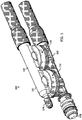
- FIG. 1 is an external view of an aspirator-check valve assembly, generally identified by reference number 100, for use in an engine, for example, in a vehicle's engine.
- the engine may be an internal combustion, and the vehicle and or engine may include a device requiring a vacuum.
- Check valves and or aspirators are often connected to an internal combustion engine before the engine throttle and after the engine throttle.
- the engine and all its components and/or subsystems are not shown in the figures, with the exception of a few boxes included to represent specific components of the engine as identified herein, and it is understood that the engine components and/or subsystems may include any commonly found in vehicle engines.
- the embodiments in the figures are referred to aspirators herein because the motive port 108 is connected to atmospheric pressure, the embodiments are not limited thereto.
- the motive port 108 may be connected to boosted pressure, such as the pressures attributed to boosted air produced by a turbocharger and as such the "aspirator device" is now preferably referred to as an ejector.
- the aspirator-check valve assemblies disclosed herein may have alternate embodiments such as the embodiment of FIGS. 1 and 2 and the embodiment of FIG. 3 100, 100', respectively. Both aspirator-check valve assemblies 100, 100' are connectable to a device requiring a vacuum 102 and create vacuum for said device 102 by the flow of air through a passageway 144, extending generally the length of a portion of the aspirator-check valve assembly, designed to create the Venturi effect.
- the aspirator-check valve assemblies 100, 100' include housing 101, which as illustrated is formed of an upper housing portion 104 and a lower housing portion 106. The designations of upper and lower portions are relative to the drawings as oriented on the page, for descriptive purposes, and are not limited to the illustrated orientation when utilized in an engine system.
- upper housing portion 104 is joined to lower housing portion 106 by sonic welding, heating, or other conventional methods for forming an airtight seal therebetween.
- the lower housing portion 106 defines passageway 144 which includes a plurality of ports, some of which are connectable to components or subsystems of the engine.
- the ports include: (1) a motive port 108, which supplies clean air from the engine intake air cleaner 170, typically obtained upstream of the throttle of the engine; (2) a suction port 110, which can connect via the check valve 111 to a device requiring vacuum 102; (3) a discharge port 112, which is connected to an engine intake manifold 172 downstream of the throttle of the engine; and, optionally, (4) a bypass port 114.
- Check valve 111 is preferably arranged to prevent fluid from flowing from the suction port 110 to the application device 102.
- the device requiring vacuum 102 is a vehicle brake boost device.
- the bypass port 114 may be connected to the device requiring vacuum 102 and, optionally, may include a check valve 120 in the fluid flow path therebetween.
- Check valve 120 is preferably arranged to prevent fluid from flowing from the bypass port 114 to the application device 102.
- lower housing portions 106 in both embodiments includes lower valve seats 124, 126.
- Each lower valve seat 124, 126 is defined by a continuous outer wall 128, 129, and, optionally, a bottom wall such as wall 130 in lower valve seat 124.
- a bore 132, 133 is defined in each lower valve seat 124, 126, respectively, to allow for air flow communication with air passageway 144.
- each lower valve seat 124, 126 includes a plurality of radially spaced fingers 134, 135 extending upwardly from an upper surface thereof. The radially spaced fingers 134, 135 serve to support a seal member 136, 137.
- both of the lower valve seats 124, 126 may include sound attenuating members rather than the plurality of radially spaced fingers.
- the upper housing portion 104 is configured for mating to or with the lower housing portion 106 to form the check valves 111, 120, if both are present.
- Upper housing portion 104 defines passageway 146 extending the length thereof and defines a plurality of ports, some of which are connectable to components or subsystems of the engine.
- the ports include: (1) a first port 148 that may be capped with cap 174 or may be connected to a component or subsystem of the engine; (2) a second port 150 (part of the inlet port for chamber/cavity 166) in fluid communication with the suction port 110 in the lower housing portion 106, and between which the seal member 136 is disposed; (3) a third port 152 (part of the inlet port for chamber/cavity 167) in fluid communication with the bypass port 114 in the lower housing portion 106, and between which the seal member 137 is disposed; and (4) a fourth port 154 which may function as an inlet connecting the aspirator-check valve assembly to a device requiring vacuum 102.
- the upper housing portion 104 in both embodiments includes upper valve seats 125, 127.
- Each upper valve seat 125, 127 is defined by continuous outer wall 160, 161 and bottom wall 162, 163.
- Both upper valve seats 125, 127 may include a pin 164, 165 extending downwardly from the bottom walls 162, 163, respectively, toward the lower housing portion 106.
- the pins 164, 165 function as a guide for translation of the sealing members 136, 137 within the cavities 166, 167 defined by the mated upper valve seat 125 with the lower valve seat 124 and defined by the mated upper valve seat 127 with the lower valve seat 126.
- each sealing member 136, 137 includes a bore therethrough sized and positioned therein for receipt of the pin 164,165 within its respective cavity 166, 167.
- the passageway 144 in the lower housing portion 106 has an inner dimension along a central longitudinal axis that includes a first tapering portion 182 (also referred to herein as the motive cone) in the motive section 180 of the lower housing portion 106 coupled to a second tapering portion 183 (also referred to herein as the discharge cone) in the discharge section 181 of the lower housing portion 106.
- first tapering portion 182 and the second tapering portion 183 are aligned end to end (outlet end 184 of the motive section 180 to inlet end 186 of the discharge section 181).
- the inlet ends 188, 186 and the outlet end 184, 189 may be any circular shape, elliptical shape, or some other polygonal form and the gradually, continuously tapering inner dimension extending therefrom may define, but is not limited to, a hyperboloid or a cone.
- Some example configurations for the outlet end 184 of the motive section 180 and inlet end 186 of the discharge section 181 are presented in FIGS. 4-6 of co-pending U.S. Patent Application No. 14/294,727, filed June 3, 2014 .
- the first tapering portion 182 terminates at a fluid junction with suction port 110, which is in fluid communication therewith, and at this junction the second tapering portion 183 begins and extends away from the first tapering portion 182.
- the second tapering portion 183 is also in fluid communication with the suction port 110.
- the second tapering portion 183 then forms a junction with the bypass port 114 proximate the outlet end 189 of the second tapering portion and is in fluid communication therewith.
- the first and second tapering portions 182,183 typically share the central longitudinal axis of the lower housing portion 106.
- the second tapering portion 183 tapers gradually, continuously from a smaller dimensioned inlet end 186 to a larger dimensioned outlet end 189.
- the optional bypass port 114 intersects the discharge section 190 as described above to be in fluid communication with the second tapering section 183.
- the bypass port 114 may intersect the second tapering section 183 adjacent to, but downstream of the outlet end 189.
- the lower housing portion 106 may thereafter, i.e., downstream of this intersection of the bypass port, continue with a cylindrically uniform inner passage until it terminates at the discharge port 112.
- Each of the respective ports 108, 110, 112, and 114 may include a connector feature on the outer surface thereof for connecting the passageway 144 to hoses or other features in the engine.
- the check valves 111 and 120 functions as follows. As the engine operates, the intake manifold 172 draws air into the motive port 180, through passageway 144 and out the discharge port 112. This creates a partial vacuum in the check valves 111, 120 and passageway 146 to draw seals 136, 137 downward against the plurality of fingers 134, 135 ( FIG. 2 ) or against the plurality of fingers 134 and the first sound attenuating member 192 ( FIG. 3 ).
- the partial vacuum created by the operation of the engine serves in the vacuum assistance of at least the operation of the device requiring vacuum 102.
- the air flow system in a typical internal combustion engine operates on the principle that as the engine operates, a partial vacuum is created which pulls air through the air intake port of the carburetor of fuel injector to aid in proper fuel combustion.
- This vacuum has been found to be useful in supplementing vacuum assist subsystems in the vehicle, particularly brakes, fuel vapor purging systems, automatic transmissions and most recently, air conditioners.
- Aspirator-check valve assemblies such as assemblies 100, 100' may provide a connection between the main airway and the subsystem and serve to inhibit back pressure from the subsystem from disturbing airflow through the main airway.
- the fluid flow within the aspirator-check valve assemblies described above is generally classified as turbulent. This means that in addition to the bulk motion of the fluid flow, such as air, there are pressure waves traveling through the assembly and different natural frequencies can become excited thereby resulting in turbulence generated noise.
- the aspirator-check valve assemblies 100, 100' as seen in FIGS. 2 and 3 include one or more sound attenuating members, 192, 194, 196.
- the sound attenuating members 192, 194, 196 are placed within the flow path proximate, but downstream of the regions where turbulence generated noise is created.
- the second sound attenuating member 194 is disposed proximate to or in the discharge port 112 because the discharge section 190 is one portion where such noise is created.
- the third sound attenuating member 196 is present and is disposed proximate to or in the fourth port 154 of passageway 146 because the flow path between the bypass port 114, check valve 120, and the fourth port 154 is one portion where such noise is created.
- the first sound attenuating member 192 is disposed within the cavity 167 of check valve 120, specifically seated within the lower valve seat 126.
- the sound attenuating members 192, 194, 196 are porous such that fluid flow through and between the passageways 144, 146 is not restricted, but sound (turbulence generated noise) is attenuated.
- the solid arrows represent the fluid flow within the aspirator-check valve assembly and the dashed arrows represent the path for travel of the turbulence generated noise.
- the porous elements are proximate but downstream of the source of the turbulent noise.
- the sound attenuating members may be positioned in the discharge port, the suction port, the bypass check valve passageway above the check valve, and or the suction check valve passageway above the check valve.
- the check valves 111, 120 can also produce turbulent noise due to the flow therethrough. This noise would travel down either of the two connections. Sound attenuating members may be placed in either the inlet or outlet passageways, and/or both of the check valves 111, 120.
- the sound attenuating members 192, 194, 196 are porous as explained above and can be made from a variety of materials including metals, plastics, ceramics, or glass.
- the sound attenuating members may be made from wire, woven or matted, sintered particles, fibers woven or matted, but are not limited thereto.
- the porous character of the sound attenuating members causes the noise pressure waves to attenuate by interfering with themselves, but should be of sufficient size and shape to not unduly restrict or interfere with fluid flow, for example, air flow.
- the sound attenuating members 192, 194, 196 are not harmed (do not deteriorate) by operating temperatures of an engine based on placement of the aspirator in the engine system. Additionally, the sound attenuating members 192, 194, 196 are not harmed by the vibrations experienced during operating conditions of the engine.
- the check valve 202 includes a housing 204 defining an internal cavity 206 having a pin 264 therein upon which is seated a sealing member 236 and defining a first port 210 in fluid communication with the internal cavity 206 and a second fluid port 212 in fluid communication with the internal cavity 206.
- the internal cavity 206 typically has larger dimensions than the first port 210 and the second port 212.
- the first port 210 and the second port 212 are positioned opposite one another to define a generally linear flow path through the check valve 202, when the sealing member 236 is not present, but is not limited to this configuration.
- the portion of the housing defining the internal cavity 206 includes an internal first seat 214 upon which the sealing member seats when the check valve is closed and a second seat 216 upon which the sealing member seats when the check valve is open.
- the second seat 216 is a plurality of radially spaced fingers 234 extending into the internal cavity 206 from an interior surface of the internal cavity that is more proximate the first port 210.
- the second seat 216 is a face or surface of a first sound attenuating member 292.
- the check valves 202, 203 each include at least one sound attenuating member.
- the first sound attenuating member 292 ( FIG. 4C ) may be positioned in the internal cavity 206 and provide the second seat 216 for the sealing member 236.
- a second sound attenuating member 294 may be included as shown in FIG. 4B proximate or in the opening defining the outlet to the first port 210.
- a third sound attenuating member 296 may be included as shown in FIG. 4B proximate or in the opening defining the inlet of the second port 212.
- a check valve may include any one or more of these first, second, and third sound attenuating members 292, 294, 296.
- the sound attenuating members are porous and may be or include any of the materials as discussed above.
- the first sound attenuating member 292 may be a disc of porous material having a generally central bore therethrough or a partial bore therein to receive the pin 264, but is not limited thereto.
- the second and third sound attenuating members 294, 296, may be generally cylindrical plugs of porous material, but are not limited thereto.
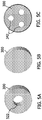
- any of the porous sound attenuating members in the embodiments described above may be a continuous plug of porous material with the only passageways therethrough being channels defined by its natural porosity, i.e., no enlarged bore holes are present.
- the continuous plug may be any shape and configuration to fit within the selected portion of the check valve or aspirator or other apparatus for generating vacuum, but as illustrated may be disc-shaped.
- the porous sound attenuating members may include one or more bore holes 322, 342 therethrough.
- the bore holes provide the benefit of minimizing unwanted bulk flow restriction within any of the embodiments described herein.
- the bore holes 322, 342 may be circular in cross-section, but are not limited thereto.
- the bore holes 322, 342 may be elliptical or polygonal in cross-section.
- Each bore hole has a generally central axis therethrough that is typically oriented generally parallel to the direction of the flow through the portion of the aspirator where the sound attenuating member 300 is disposed. As seen in FIG.
- a single bore hole 322 may be generally centrally positioned within the sound attenuating member 300, but is not limited thereto.
- the dimensions of the bore hole 322 are typically smaller than the internal dimensions of the upstream passageway adjacent to the sound attenuating member 300.
- the diameter of the bore hole 322 may be about 8 mm to about 14 mm.
- a plurality of bore holes 342 are present and are symmetrically positioned relative to one another within the porous sound attenuating member 300. These bore holes 342 may be circular in cross-section as shown, but are not limited thereto, and may be non-symmetrically arranged if desired. As described for FIG.
- the dimensions of the bore holes 342 are smaller than the internal dimensions of the upstream passageway adjacent to the sound attenuating member 300.
- the diameter of each may be about 3 mm to about 5 mm.
- the sound attenuating members 300 may be generally doughnut or toroidal in shape thereby having an inner diameter, an outer diameter and a thickness.
- the inner diameter may be the same or slightly larger than the flow path.
- the outer diameter and thickness are variable and are selected based on the required level of sound attenuation necessary during operating conditions.
- any of the sound attenuating members may be made from a 0.05 mm diameter continuous strand of stainless steel wire that is woven into a cylindrical mesh, flattened and then wound to the selected outer diameter.
- the density of the weave may be about 0.24 mg/mm 3 to about 0.35 mg/mm 3 . In one embodiment, the density of the weave is within this range and is about 0.3 mg/mm 3 . A density of the weave within this range is achievable by varying the wire diameter, the structure of the weave, and the tension in winding the cylindrical mesh to the selected outer diameter.
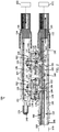
- FIGS. 6A and 6B , 7A and 7B , and 8A and 8B are of alternate embodiments of aspirators 400, 401, and 402, respectively. Reference numbers identifying similar or the same components as described for FIGS. 1-3 are used in these figures as well.
- Each of these aspirators 400, 401, 402 include a porous sound attenuating member 300 within passage way 144 downstream of the bore 132 of a Venturi portion and disposed in the discharge section 181 (the outlet port of chamber 166). So, as seen in FIGS. 6B , 7B , and 8B , the sound attenuating member 300 is after the bore 132 and before the bypass port 114.
- the sound attenuating member is shown to be the sound attenuating member of FIG. 5A , but of course is not limited thereto.
- FIGS. 6A and 6B has three primary housing pieces: (1) the upper housing 104 as described above and the lower housing 106 described above, but split into a (2) Venturi portion 106a and (3) a bypass portion 106b.
- the Venturi portion 106a includes a motive port 108 that may include a hose connector 410 on the outer exterior surface defining the motive port 108, a motive cone 182, a suction Venturi 132, the lower half of the check valve 111, specifically the lower valve seat 124, and a discharge cone 183 terminating in a first canister portion 412.
- the bypass portion 106b includes a second canister portion 414 matable with the first canister portion 412 to enclose the sound attenuating member 300 in an enclosed chamber 420 defined by canister 416 formed when the first and second canister portions 412, 414 are mated together.
- the bypass portion 106b also includes a bypass port 114 and the lower half of the check valve 120, specifically the lower seat 126, and discharge port 112 that may include a hose connector 418 on the outer exterior surface defining the discharge part 112.
- a first check valve disc 136 is seated in check valve 111 and a second check valve disc 137 is seated in check valve 120.
- FIGS. 7A and 7B similar to the embodiment of FIGS. 6A and 6B , has three primary housing pieces: (1) the upper housing 104, and the lower housing 106 described above, but split into a (2) Venturi portion 106a' and (3) a bypass portion 106b'.
- the Venturi portion 106a' is the same as disclosed in FIG. 6B except that upstream of where the discharge cone 183 terminates in a first canister portion 412, a collar 424 extends radially outward from the exterior surface of the discharge cone 183. As seen in FIG. 7B , the collar 424 is positioned between the bore 132 and the first canister portion 412.
- the bypass portion 106b' is the same as disclosed in FIG.
- the second canister portion 414' is configured to extend beyond the first canister portion 412 to mate to or be coupled to the collar 424.
- the first canister portion 412 and the second canister portion 414' are mated together they enclose a sound attenuating member 300 therebetween in an enclosed chamber 420' and also form a second chamber 426 located between the collar 424 and the first canister portion 412.
- the canister 417 is dual chambered having the second chamber 426 surrounding the outside of the discharge cone 183 upstream from the first chamber 420' housing the sound attenuating member 300.
- the second chamber 426 contains air and may be sealed to contain the air or may be in fluid communication with ambient air surrounding the aspirator 401.
- the second chamber 426 may include a second sound attenuating member, which may be a porous material that does or does not include bore holes such as those shown in FIGS. 5A and 5C .
- the aspirator 401 also includes, a first check valve disc 136 seated in check valve 111 between the upper housing 104 and the Venturi portion 106a' and a second check valve disc 137 seated in check valve 120 between the upper housing 104 and the bypass portion 106b'.
- the bypass portion 106b' includes one or more fingers 490 extending into the bore 322 of the sound attenuating member 300 at a position that places the fingers generally against a surface thereof that defines the outermost diameter or dimension of the bore 322. If a plurality of fingers 490 are present, they may be equally distant apart from adjacent neighboring fingers 490.
- the one or more fingers 490 provide the advantage of maintaining the sound attenuating member in its install position and to reduce deformation of the material during operating conditions of the system. While the finger 490 is shown as part of the bypass portion 106b', in another embodiment, the fingers could instead extend from the Venturi portion 106a'.
- FIGS. 8A and 8B is essentially the embodiment of FIGS. 6A and 6B , but divided into two subassemblies 430, 440, one of which includes a sound attenuating canister 458, joinable into fluid communication by one or more hoses 450.
- the embodiment of FIGS. 7A and 7B could also be divided into two subassemblies as well in a similar fashion even though not illustrated in the figures.
- the subassemblies include a Venturi subassembly 430 and a bypass subassembly 440.
- the Venturi subassembly 430 includes a first upper housing portion 432 that includes the upper valve seat 125 as described above and a lower Venturi portion 106 as described in FIG. 6B , which terminates with a first canister portion 412.
- a first check valve disc 136 is seated between the upper valve seat 125 and the lower valve seat 126 to form check valve 111.
- the Venturi portion 106a includes a motive port 108 that may include a hose connector 410 on the outer exterior surface defining the motive port 108, a motive cone 182, a suction Venturi 132, the lower half of the check valve 111, specifically the lower valve seat 124, and a discharge cone 183 terminating in a first canister portion 412.
- a canister cap 460 comprising a second canister portion 462 and a connector portion 464 having hose connecting features 466 on its exterior surface.
- the second canister portion 462 is matable with the first canister portion 412 to enclose the sound attenuating member 300 in an enclosed chamber 470 formed therebetween when the first and second canister portions 412, 414 are mated together.
- the first upper housing 430 may include a first stabilizing member 480 facing the lower Venturi portion 106 and positioned to mate with a second stabilizing member 482 included as part of the lower Venturi portion 106.
- the assembled aspirator 402 has the first stabilizing member 480 mated with the second stabilizing member 482 to stiffen and strengthen the aspirator, in particular the half of the aspirator having the sound attenuating canister 458.
- the bypass subassembly 440 includes a second upper housing portion 434 and a lower bypass portion 106c.
- the second upper housing portion 434 includes an upper valve seat 125 defining, as described above, a portion of check valve 120 and the third port 152, which is in fluid communication with the bypass port 114 in the lower bypass housing portion 106c.
- the second upper housing portion 434 also includes a conduit 472 having a fifth port 474 connectable to a sixth port 436 of the first upper housing portion 432 by a hose 450.
- the upper bypass housing portion 434 also includes the fourth port 154, described above, which may function as an inlet connecting the aspirator-check valve assembly 402 to a device requiring vacuum.
- the lower bypass housing portion 106c includes the bypass port 114, the lower half of the check valve 120, specifically the lower valve seat 126, and the discharge port 112 that may include a hose connecting features 418 on its outer exterior surface.
- the canister cap 460 includes one or more fingers 490' extending into the bore 322 of the sound attenuating member 300 at a position that places the fingers generally against a surface thereof that defines the outermost diameter or dimension of the bore 322. If a plurality of fingers 490' are present, they may be equally distant apart from adjacent neighboring fingers 490'.
- the one or more fingers 490' provide the advantage of maintaining the sound attenuating member in its install position and to reduce deformation of the material during operating conditions of the system. While the finger 490' is shown as part of the canister cap 460, in another embodiment, the fingers could instead extend from the Venturi portion 106a.
- each of the various embodiments herein is that the noise generated, typically from turbulent flow through the device and the operation of the Venturi portion and/or the check valves, is reduced. This is beneficial to a user who expects a quiet operating system.
Claims (6)
- Unité de logement d'un dispositif venturi (400, 401, 402) comprenant :une partie venturi (106a, 106a') définissant une voie de passage interne (144) ayant une section motrice (180) alignée bout à bout avec une section d'évacuation (181), et définissant un alésage (132) en communication fluidique avec la voie de passage interne (144) ;une première extrémité de la partie venturi définit un orifice moteur (108) de la voie de passage interne (144), la section motrice (180) se rétrécissant vers un raccord fluidique entre une extrémité de sortie (184) de la section motrice et une extrémité d'entrée (186) de la section d'évacuation (181), et le raccord fluidique est en communication fluidique avec l'alésage (132) ;un extérieur de la partie venturi comprend une pluralité de doigts (134) circonférentiellement espacés autour de l'alésage (132) et faisant saillie depuis la voie de passage interne (144) ; caractérisée en ce que une seconde extrémité de la partie venturi définit une première partie contenant (412) ayant une extrémité ouverte formée pour recevoir un élément d'atténuation du son et pouvant être accouplée à une seconde partie contenant (414, 414', 462) pour entourer l'élément d'atténuation du son (300).
- Unité de logement selon la revendication 1, comprenant en outre une partie de dérivation (106b, 106c) ou un capuchon de contenant (460) définissant une seconde partie contenant (414, 414', 462) accouplée à la première partie contenant (412) et définissant une seconde partie de la voie de passage interne (144).
- Unité de logement selon la revendication 2, dans laquelle la seconde partie contenant (414') de la partie de dérivation (106b, 106c) a une longueur s'étendant au-delà de la première partie contenant (412) pour définir un contenant à double chambre logeant un élément d'atténuation du son (300) dans une première chambre (420) la plus proche d'une extrémité de sortie de la section d'évacuation (181) et une seconde chambre (426) en amont de la première chambre (420).
- Unité de logement selon la revendication 1, comprenant en outre un premier élément d'atténuation du son (300) disposé dans la première partie contenant (412).
- Unité de logement selon la revendication 4, dans laquelle le premier matériau d'atténuation du son (300) présente un ou plusieurs alésages (322, 342) passant à travers celui-ci qui sont généralement alignés dans la direction de l'écoulement dans la voie d'écoulement, les alésages étant plus petits qu'une dimension interne de la voie de passage en amont adjacente au premier et/ou au second bouchon de matériau d'atténuation du son.
- Unité de logement selon la revendication 5, dans laquelle le premier élément d'atténuation du son (300) atténue les ondes de pression sonore par interférence et est résistant aux températures présentes dans un moteur à combustion interne.
Applications Claiming Priority (4)
| Application Number | Priority Date | Filing Date | Title |
|---|---|---|---|
| US201361888186P | 2013-10-08 | 2013-10-08 | |
| US201361913756P | 2013-12-09 | 2013-12-09 | |
| PCT/US2014/059672 WO2015054372A2 (fr) | 2013-10-08 | 2014-10-08 | Atténuation de bruit dans une unité clapet de retenue ou appareil de production de vide |
| EP14852220.4A EP3055597B1 (fr) | 2013-10-08 | 2014-10-08 | Atténuation de bruit dans une unité clapet de retenue ou appareil de production de vide |
Related Parent Applications (1)
| Application Number | Title | Priority Date | Filing Date |
|---|---|---|---|
| EP14852220.4A Division EP3055597B1 (fr) | 2013-10-08 | 2014-10-08 | Atténuation de bruit dans une unité clapet de retenue ou appareil de production de vide |
Publications (2)
| Publication Number | Publication Date |
|---|---|
| EP3505801A1 EP3505801A1 (fr) | 2019-07-03 |
| EP3505801B1 true EP3505801B1 (fr) | 2020-06-17 |
Family
ID=52775988
Family Applications (2)
| Application Number | Title | Priority Date | Filing Date |
|---|---|---|---|
| EP19157773.3A Active EP3505801B1 (fr) | 2013-10-08 | 2014-10-08 | Atténuation du bruit dans une unité de soupape anti-retour ou un appareil de production de vide |
| EP14852220.4A Active EP3055597B1 (fr) | 2013-10-08 | 2014-10-08 | Atténuation de bruit dans une unité clapet de retenue ou appareil de production de vide |
Family Applications After (1)
| Application Number | Title | Priority Date | Filing Date |
|---|---|---|---|
| EP14852220.4A Active EP3055597B1 (fr) | 2013-10-08 | 2014-10-08 | Atténuation de bruit dans une unité clapet de retenue ou appareil de production de vide |
Country Status (7)
| Country | Link |
|---|---|
| US (1) | US9534704B2 (fr) |
| EP (2) | EP3505801B1 (fr) |
| JP (1) | JP6632973B2 (fr) |
| KR (1) | KR102184253B1 (fr) |
| CN (1) | CN105051434B (fr) |
| BR (2) | BR122020011348B1 (fr) |
| WO (1) | WO2015054372A2 (fr) |
Families Citing this family (14)
| Publication number | Priority date | Publication date | Assignee | Title |
|---|---|---|---|---|
| CN105378240B (zh) * | 2014-06-06 | 2018-10-09 | 戴科知识产权控股有限责任公司 | 文丘里装置和/或止回阀中的噪声衰减 |
| USD821302S1 (en) * | 2015-06-19 | 2018-06-26 | Dayco Ip Holdings, Llc | Venturi device |
| BR112018076038B1 (pt) * | 2016-06-14 | 2023-05-02 | Dayco Ip Holdings, Llc | Dispositivo venturi e motor de combustão interna |
| WO2017218126A1 (fr) * | 2016-06-14 | 2017-12-21 | Dayco Ip Holdings, Llc | Clapets antiretour et dispositifs venturi comportant ceux-ci |
| JP7008691B2 (ja) * | 2016-09-21 | 2022-01-25 | デイコ アイピー ホールディングス,エルエルシー | 真空を生むためのベンチュリデバイスのベンチュリギャップ内のバルブゲート |
| EP3685041B1 (fr) | 2017-09-21 | 2023-05-10 | Dayco IP Holdings, LLC | Pompe à vide activée par solénoïde pour un système de moteur et système équipé de celle-ci |
| US11486504B2 (en) | 2018-04-23 | 2022-11-01 | Dayco Ip Holdings, Llc | Check valve insert defining an open position and check valves having same |
| WO2022051768A1 (fr) | 2020-09-07 | 2022-03-10 | Dayco Ip Holdings, Llc | Soupape à verrouillage magnétique pour des systèmes de gestion de vapeur de carburant et systèmes incorporant celle-ci |
| US11415086B2 (en) | 2020-09-07 | 2022-08-16 | Dayco Ip Holdings, Llc | Three port, five-way magnetically latching valve for fuel vapor management systems and systems incorporating same |
| US11499559B2 (en) | 2020-10-30 | 2022-11-15 | Delphi Technologies Ip Limited | Fluid pump and outlet check valve assembly thereof |
| WO2022178346A1 (fr) | 2021-02-22 | 2022-08-25 | Dayco Ip Holdings, Llc | Système et procédés pour une pompe de régulation de pression de réservoir de carburant |
| EP4339048A1 (fr) * | 2022-09-13 | 2024-03-20 | KNORR-BREMSE Systeme für Nutzfahrzeuge GmbH | Silencieux amélioré pour systèmes à gaz comprimé |
| EP4339046A1 (fr) * | 2022-09-13 | 2024-03-20 | KNORR-BREMSE Systeme für Nutzfahrzeuge GmbH | Silencieux modulaire à faible bruit pour véhicules utilitaires |
| EP4339047A1 (fr) * | 2022-09-13 | 2024-03-20 | KNORR-BREMSE Systeme für Nutzfahrzeuge GmbH | Silencieux avec jupe pour systèmes à gaz comprimé |
Family Cites Families (49)
| Publication number | Priority date | Publication date | Assignee | Title |
|---|---|---|---|---|
| US2037884A (en) | 1932-11-11 | 1936-04-21 | Burgess Lab Inc C F | Silencer |
| US2626009A (en) | 1950-04-11 | 1953-01-20 | Houdaille Hershey Corp | Air cleaner, intake silencer, and carburetor housing unit |
| US2954091A (en) | 1956-06-18 | 1960-09-27 | Gen Motors Corp | Cleaner silencer assembly |
| US2905268A (en) | 1956-10-29 | 1959-09-22 | Gen Motors Corp | Cleaner silencer assembly |
| US3430437A (en) * | 1966-10-05 | 1969-03-04 | Holley Carburetor Co | Automotive exhaust emission system |
| DE1750021A1 (de) | 1968-03-21 | 1971-01-07 | Fichtel & Sachs Ag | Ventileinrichtung fuer hydraulische,pneumatische oder hydropneumatische Einrichtungen |
| US3826281A (en) * | 1969-10-29 | 1974-07-30 | Us Navy | Throttling ball valve |
| US3698510A (en) | 1971-08-04 | 1972-10-17 | Blatt Leland F | Safety silencer air nozzle |
| US3842932A (en) | 1972-11-01 | 1974-10-22 | S Gibel | Sound-trap muffler |
| US3765505A (en) * | 1972-11-15 | 1973-10-16 | Vac U Max | Noise suppressed venturi power unit |
| US4056334A (en) * | 1975-05-12 | 1977-11-01 | Fortune William S | Vacuum system |
| US4354492A (en) | 1979-04-16 | 1982-10-19 | American Hospital Supply Corporation | Medical administration set with backflow check valve |
| IT8104805V0 (it) | 1981-03-31 | 1981-03-31 | Panda Srl | Silenziatore di scarico, in particolare per pistole e attrezzature pneumatiche |
| JPS6029366A (ja) * | 1983-07-28 | 1985-02-14 | Nissin Kogyo Kk | 車両用負圧式倍力装置の負圧源装置 |
| DE3482560D1 (de) * | 1983-11-17 | 1990-07-26 | John Sidney Howell | Schalldaempfer. |
| US4683916A (en) | 1986-09-25 | 1987-08-04 | Burron Medical Inc. | Normally closed automatic reflux valve |
| JPH01111878U (fr) * | 1988-01-22 | 1989-07-27 | ||
| US4893654A (en) * | 1988-07-08 | 1990-01-16 | Feuz John G | Double check valve backflow preventer assembly |
| US4951708A (en) * | 1988-11-30 | 1990-08-28 | General Motors Corporation | Vacuum check valve |
| NL9000339A (nl) * | 1990-02-13 | 1991-09-02 | System Engineering & Component | Drukvalreductie-inrichting, en klep voorzien van een drukvalreductie-inrichting. |
| US4938309A (en) | 1989-06-08 | 1990-07-03 | M.D. Manufacturing, Inc. | Built-in vacuum cleaning system with improved acoustic damping design |
| US5108266A (en) | 1991-05-29 | 1992-04-28 | Allied-Signal Inc. | Check valve with aspirating function |
| US5291916A (en) | 1992-12-28 | 1994-03-08 | Excel Industries, Inc. | Check valve |
| US5326942A (en) | 1993-02-09 | 1994-07-05 | Schmid Jerry W | Noise suppression muffler for moisture laden exhaust gases & method |
| JPH08174860A (ja) * | 1994-10-26 | 1996-07-09 | Seiko Epson Corp | インクジェットプリンタ用インクカートリッジ |
| US6382931B1 (en) | 1998-02-24 | 2002-05-07 | Respironics, Inc. | Compressor muffler |
| CN2400655Y (zh) * | 1999-11-23 | 2000-10-11 | 屠申富 | 车用限压单向阀 |
| WO2003023229A1 (fr) * | 2001-09-06 | 2003-03-20 | Ulvac, Inc. | Systeme de pompe a vide et procede de fonctionnement d'un systeme de pompe a vide |
| US6988510B2 (en) * | 2002-03-22 | 2006-01-24 | Halkey-Roberts Corporation | Disc check valve |
| US20050061378A1 (en) | 2003-08-01 | 2005-03-24 | Foret Todd L. | Multi-stage eductor apparatus |
| CN1279868C (zh) | 2003-08-26 | 2006-10-18 | 苏州金莱克清洁器具有限公司 | 吸尘器消音装置 |
| US20050121084A1 (en) | 2003-12-04 | 2005-06-09 | Danfoss Flomatic Corporation | Ball check valve |
| US7673653B2 (en) | 2004-06-17 | 2010-03-09 | Filtertek Inc. | Check valve |
| US20060016477A1 (en) * | 2004-07-23 | 2006-01-26 | Algis Zaparackas | Vacuum enhancing check valve |
| SE0502371L (sv) * | 2005-10-27 | 2006-09-19 | Xerex Ab | Ejektor med monteringshylsa, samt monteringsförfarande |
| WO2007140519A1 (fr) | 2006-06-05 | 2007-12-13 | Cullin Innovation Pty Ltd | Régulateur de fluide |
| JP4238882B2 (ja) | 2006-06-09 | 2009-03-18 | トヨタ自動車株式会社 | 車両用エゼクタシステム |
| JP2009544978A (ja) * | 2006-07-25 | 2009-12-17 | ウオーターズ・テクノロジーズ・コーポレイシヨン | 弾性封止逆止弁 |
| US7628170B2 (en) | 2007-09-05 | 2009-12-08 | Emerson Electric Co. | Flow control valve |
| JP5085348B2 (ja) * | 2008-01-16 | 2012-11-28 | 株式会社パイオラックス | 弁装置 |
| CN201377408Y (zh) * | 2009-03-31 | 2010-01-06 | 台州职业技术学院 | 适用于干式真空泵的组合式消声器 |
| US20110186151A1 (en) | 2010-02-04 | 2011-08-04 | Bernard Joseph Sparazynski | Check valve |
| US8925520B2 (en) | 2010-03-10 | 2015-01-06 | Ford Global Technologies, Llc | Intake system including vacuum aspirator |
| DE102010033091A1 (de) | 2010-08-02 | 2012-02-02 | Schaeffler Technologies Gmbh & Co. Kg | Hydraulisches Spannausgleichselement |
| CN201907500U (zh) * | 2010-12-22 | 2011-07-27 | 安徽江淮汽车股份有限公司 | 一种汽车用单向阀 |
| WO2013025991A2 (fr) | 2011-08-17 | 2013-02-21 | Hendrickson Usa, L.L.C. | Système d'évacuation pour essieu de véhicule |
| US10337628B2 (en) * | 2012-02-20 | 2019-07-02 | Nyloncraft Incorporated | High mass flow check valve aspirator |
| US9097149B2 (en) | 2012-07-13 | 2015-08-04 | Ford Global Technologies, Llc | Aspirator for crankcase ventilation and vacuum generation |
| US9441557B2 (en) | 2012-12-13 | 2016-09-13 | Ford Global Technologies, Llc | Method and system for vacuum generation |
-
2014
- 2014-10-08 BR BR122020011348-0A patent/BR122020011348B1/pt active IP Right Grant
- 2014-10-08 EP EP19157773.3A patent/EP3505801B1/fr active Active
- 2014-10-08 BR BR112016007686-9A patent/BR112016007686B1/pt active IP Right Grant
- 2014-10-08 KR KR1020167011562A patent/KR102184253B1/ko active IP Right Grant
- 2014-10-08 JP JP2016521267A patent/JP6632973B2/ja active Active
- 2014-10-08 CN CN201480001422.9A patent/CN105051434B/zh active Active
- 2014-10-08 WO PCT/US2014/059672 patent/WO2015054372A2/fr active Application Filing
- 2014-10-08 US US14/509,612 patent/US9534704B2/en active Active
- 2014-10-08 EP EP14852220.4A patent/EP3055597B1/fr active Active
Non-Patent Citations (1)
| Title |
|---|
| None * |
Also Published As
| Publication number | Publication date |
|---|---|
| WO2015054372A3 (fr) | 2015-06-04 |
| EP3055597A2 (fr) | 2016-08-17 |
| EP3055597A4 (fr) | 2017-06-07 |
| EP3055597B1 (fr) | 2019-02-27 |
| EP3505801A1 (fr) | 2019-07-03 |
| JP2016534288A (ja) | 2016-11-04 |
| BR112016007686A2 (pt) | 2017-08-01 |
| US20150096637A1 (en) | 2015-04-09 |
| KR20160067987A (ko) | 2016-06-14 |
| BR112016007686B1 (pt) | 2022-07-26 |
| US9534704B2 (en) | 2017-01-03 |
| CN105051434A (zh) | 2015-11-11 |
| WO2015054372A2 (fr) | 2015-04-16 |
| KR102184253B1 (ko) | 2020-11-30 |
| CN105051434B (zh) | 2017-07-07 |
| JP6632973B2 (ja) | 2020-01-22 |
| BR122020011348B1 (pt) | 2022-08-16 |
Similar Documents
| Publication | Publication Date | Title |
|---|---|---|
| EP3505801B1 (fr) | Atténuation du bruit dans une unité de soupape anti-retour ou un appareil de production de vide | |
| US10473235B2 (en) | Bypass check valve and Venturi having same | |
| JP2019215085A (ja) | エンジンシステムのノイズ減衰ユニット | |
| EP3152417B1 (fr) | Atténuation de bruit dans un dispositif venturi et/ou des clapets anti-retour | |
| EP3822136A1 (fr) | Clapets antiretour et dispositifs venturi comportant ceux-ci | |
| KR102370863B1 (ko) | 진공 생성 장치의 바이패스 밸브 |
Legal Events
| Date | Code | Title | Description |
|---|---|---|---|
| PUAI | Public reference made under article 153(3) epc to a published international application that has entered the european phase |
Free format text: ORIGINAL CODE: 0009012 |
|
| STAA | Information on the status of an ep patent application or granted ep patent |
Free format text: STATUS: THE APPLICATION HAS BEEN PUBLISHED |
|
| AC | Divisional application: reference to earlier application |
Ref document number: 3055597 Country of ref document: EP Kind code of ref document: P |
|
| AK | Designated contracting states |
Kind code of ref document: A1 Designated state(s): AL AT BE BG CH CY CZ DE DK EE ES FI FR GB GR HR HU IE IS IT LI LT LU LV MC MK MT NL NO PL PT RO RS SE SI SK SM TR |
|
| STAA | Information on the status of an ep patent application or granted ep patent |
Free format text: STATUS: REQUEST FOR EXAMINATION WAS MADE |
|
| 17P | Request for examination filed |
Effective date: 20191121 |
|
| RBV | Designated contracting states (corrected) |
Designated state(s): AL AT BE BG CH CY CZ DE DK EE ES FI FR GB GR HR HU IE IS IT LI LT LU LV MC MK MT NL NO PL PT RO RS SE SI SK SM TR |
|
| RIC1 | Information provided on ipc code assigned before grant |
Ipc: F16K 47/00 20060101ALI20191211BHEP Ipc: F02M 35/12 20060101ALI20191211BHEP Ipc: F16K 15/00 20060101AFI20191211BHEP Ipc: F02M 35/10 20060101ALI20191211BHEP |
|
| GRAP | Despatch of communication of intention to grant a patent |
Free format text: ORIGINAL CODE: EPIDOSNIGR1 |
|
| STAA | Information on the status of an ep patent application or granted ep patent |
Free format text: STATUS: GRANT OF PATENT IS INTENDED |
|
| INTG | Intention to grant announced |
Effective date: 20200117 |
|
| RIN1 | Information on inventor provided before grant (corrected) |
Inventor name: GILMER, MATT Inventor name: FLETCHER, DAVID E. Inventor name: HAMPTON, KEITH Inventor name: GRAICHEN, BRIAN M. Inventor name: BRAVO, REX Inventor name: NIEDERT, ANDREW |
|
| GRAS | Grant fee paid |
Free format text: ORIGINAL CODE: EPIDOSNIGR3 |
|
| GRAA | (expected) grant |
Free format text: ORIGINAL CODE: 0009210 |
|
| STAA | Information on the status of an ep patent application or granted ep patent |
Free format text: STATUS: THE PATENT HAS BEEN GRANTED |
|
| AC | Divisional application: reference to earlier application |
Ref document number: 3055597 Country of ref document: EP Kind code of ref document: P |
|
| AK | Designated contracting states |
Kind code of ref document: B1 Designated state(s): AL AT BE BG CH CY CZ DE DK EE ES FI FR GB GR HR HU IE IS IT LI LT LU LV MC MK MT NL NO PL PT RO RS SE SI SK SM TR |
|
| REG | Reference to a national code |
Ref country code: GB Ref legal event code: FG4D |
|
| REG | Reference to a national code |
Ref country code: CH Ref legal event code: EP |
|
| REG | Reference to a national code |
Ref country code: DE Ref legal event code: R096 Ref document number: 602014066901 Country of ref document: DE |
|
| REG | Reference to a national code |
Ref country code: IE Ref legal event code: FG4D |
|
| REG | Reference to a national code |
Ref country code: AT Ref legal event code: REF Ref document number: 1281716 Country of ref document: AT Kind code of ref document: T Effective date: 20200715 |
|
| PG25 | Lapsed in a contracting state [announced via postgrant information from national office to epo] |
Ref country code: SE Free format text: LAPSE BECAUSE OF FAILURE TO SUBMIT A TRANSLATION OF THE DESCRIPTION OR TO PAY THE FEE WITHIN THE PRESCRIBED TIME-LIMIT Effective date: 20200617 Ref country code: GR Free format text: LAPSE BECAUSE OF FAILURE TO SUBMIT A TRANSLATION OF THE DESCRIPTION OR TO PAY THE FEE WITHIN THE PRESCRIBED TIME-LIMIT Effective date: 20200918 Ref country code: NO Free format text: LAPSE BECAUSE OF FAILURE TO SUBMIT A TRANSLATION OF THE DESCRIPTION OR TO PAY THE FEE WITHIN THE PRESCRIBED TIME-LIMIT Effective date: 20200917 Ref country code: LT Free format text: LAPSE BECAUSE OF FAILURE TO SUBMIT A TRANSLATION OF THE DESCRIPTION OR TO PAY THE FEE WITHIN THE PRESCRIBED TIME-LIMIT Effective date: 20200617 Ref country code: FI Free format text: LAPSE BECAUSE OF FAILURE TO SUBMIT A TRANSLATION OF THE DESCRIPTION OR TO PAY THE FEE WITHIN THE PRESCRIBED TIME-LIMIT Effective date: 20200617 |
|
| REG | Reference to a national code |
Ref country code: LT Ref legal event code: MG4D |
|
| REG | Reference to a national code |
Ref country code: NL Ref legal event code: MP Effective date: 20200617 |
|
| PG25 | Lapsed in a contracting state [announced via postgrant information from national office to epo] |
Ref country code: LV Free format text: LAPSE BECAUSE OF FAILURE TO SUBMIT A TRANSLATION OF THE DESCRIPTION OR TO PAY THE FEE WITHIN THE PRESCRIBED TIME-LIMIT Effective date: 20200617 Ref country code: HR Free format text: LAPSE BECAUSE OF FAILURE TO SUBMIT A TRANSLATION OF THE DESCRIPTION OR TO PAY THE FEE WITHIN THE PRESCRIBED TIME-LIMIT Effective date: 20200617 Ref country code: BG Free format text: LAPSE BECAUSE OF FAILURE TO SUBMIT A TRANSLATION OF THE DESCRIPTION OR TO PAY THE FEE WITHIN THE PRESCRIBED TIME-LIMIT Effective date: 20200917 Ref country code: RS Free format text: LAPSE BECAUSE OF FAILURE TO SUBMIT A TRANSLATION OF THE DESCRIPTION OR TO PAY THE FEE WITHIN THE PRESCRIBED TIME-LIMIT Effective date: 20200617 |
|
| REG | Reference to a national code |
Ref country code: AT Ref legal event code: MK05 Ref document number: 1281716 Country of ref document: AT Kind code of ref document: T Effective date: 20200617 |
|
| PG25 | Lapsed in a contracting state [announced via postgrant information from national office to epo] |
Ref country code: NL Free format text: LAPSE BECAUSE OF FAILURE TO SUBMIT A TRANSLATION OF THE DESCRIPTION OR TO PAY THE FEE WITHIN THE PRESCRIBED TIME-LIMIT Effective date: 20200617 Ref country code: AL Free format text: LAPSE BECAUSE OF FAILURE TO SUBMIT A TRANSLATION OF THE DESCRIPTION OR TO PAY THE FEE WITHIN THE PRESCRIBED TIME-LIMIT Effective date: 20200617 |
|
| PG25 | Lapsed in a contracting state [announced via postgrant information from national office to epo] |
Ref country code: SM Free format text: LAPSE BECAUSE OF FAILURE TO SUBMIT A TRANSLATION OF THE DESCRIPTION OR TO PAY THE FEE WITHIN THE PRESCRIBED TIME-LIMIT Effective date: 20200617 Ref country code: IT Free format text: LAPSE BECAUSE OF FAILURE TO SUBMIT A TRANSLATION OF THE DESCRIPTION OR TO PAY THE FEE WITHIN THE PRESCRIBED TIME-LIMIT Effective date: 20200617 Ref country code: ES Free format text: LAPSE BECAUSE OF FAILURE TO SUBMIT A TRANSLATION OF THE DESCRIPTION OR TO PAY THE FEE WITHIN THE PRESCRIBED TIME-LIMIT Effective date: 20200617 Ref country code: PT Free format text: LAPSE BECAUSE OF FAILURE TO SUBMIT A TRANSLATION OF THE DESCRIPTION OR TO PAY THE FEE WITHIN THE PRESCRIBED TIME-LIMIT Effective date: 20201019 Ref country code: AT Free format text: LAPSE BECAUSE OF FAILURE TO SUBMIT A TRANSLATION OF THE DESCRIPTION OR TO PAY THE FEE WITHIN THE PRESCRIBED TIME-LIMIT Effective date: 20200617 Ref country code: EE Free format text: LAPSE BECAUSE OF FAILURE TO SUBMIT A TRANSLATION OF THE DESCRIPTION OR TO PAY THE FEE WITHIN THE PRESCRIBED TIME-LIMIT Effective date: 20200617 Ref country code: CZ Free format text: LAPSE BECAUSE OF FAILURE TO SUBMIT A TRANSLATION OF THE DESCRIPTION OR TO PAY THE FEE WITHIN THE PRESCRIBED TIME-LIMIT Effective date: 20200617 Ref country code: RO Free format text: LAPSE BECAUSE OF FAILURE TO SUBMIT A TRANSLATION OF THE DESCRIPTION OR TO PAY THE FEE WITHIN THE PRESCRIBED TIME-LIMIT Effective date: 20200617 |
|
| PG25 | Lapsed in a contracting state [announced via postgrant information from national office to epo] |
Ref country code: PL Free format text: LAPSE BECAUSE OF FAILURE TO SUBMIT A TRANSLATION OF THE DESCRIPTION OR TO PAY THE FEE WITHIN THE PRESCRIBED TIME-LIMIT Effective date: 20200617 Ref country code: SK Free format text: LAPSE BECAUSE OF FAILURE TO SUBMIT A TRANSLATION OF THE DESCRIPTION OR TO PAY THE FEE WITHIN THE PRESCRIBED TIME-LIMIT Effective date: 20200617 Ref country code: IS Free format text: LAPSE BECAUSE OF FAILURE TO SUBMIT A TRANSLATION OF THE DESCRIPTION OR TO PAY THE FEE WITHIN THE PRESCRIBED TIME-LIMIT Effective date: 20201017 |
|
| REG | Reference to a national code |
Ref country code: DE Ref legal event code: R097 Ref document number: 602014066901 Country of ref document: DE |
|
| PLBE | No opposition filed within time limit |
Free format text: ORIGINAL CODE: 0009261 |
|
| STAA | Information on the status of an ep patent application or granted ep patent |
Free format text: STATUS: NO OPPOSITION FILED WITHIN TIME LIMIT |
|
| PG25 | Lapsed in a contracting state [announced via postgrant information from national office to epo] |
Ref country code: DK Free format text: LAPSE BECAUSE OF FAILURE TO SUBMIT A TRANSLATION OF THE DESCRIPTION OR TO PAY THE FEE WITHIN THE PRESCRIBED TIME-LIMIT Effective date: 20200617 |
|
| 26N | No opposition filed |
Effective date: 20210318 |
|
| PG25 | Lapsed in a contracting state [announced via postgrant information from national office to epo] |
Ref country code: SI Free format text: LAPSE BECAUSE OF FAILURE TO SUBMIT A TRANSLATION OF THE DESCRIPTION OR TO PAY THE FEE WITHIN THE PRESCRIBED TIME-LIMIT Effective date: 20200617 |
|
| REG | Reference to a national code |
Ref country code: CH Ref legal event code: PL |
|
| GBPC | Gb: european patent ceased through non-payment of renewal fee |
Effective date: 20201008 |
|
| PG25 | Lapsed in a contracting state [announced via postgrant information from national office to epo] |
Ref country code: MC Free format text: LAPSE BECAUSE OF FAILURE TO SUBMIT A TRANSLATION OF THE DESCRIPTION OR TO PAY THE FEE WITHIN THE PRESCRIBED TIME-LIMIT Effective date: 20200617 Ref country code: LU Free format text: LAPSE BECAUSE OF NON-PAYMENT OF DUE FEES Effective date: 20201008 |
|
| REG | Reference to a national code |
Ref country code: BE Ref legal event code: MM Effective date: 20201031 |
|
| PG25 | Lapsed in a contracting state [announced via postgrant information from national office to epo] |
Ref country code: FR Free format text: LAPSE BECAUSE OF NON-PAYMENT OF DUE FEES Effective date: 20201031 |
|
| PG25 | Lapsed in a contracting state [announced via postgrant information from national office to epo] |
Ref country code: LI Free format text: LAPSE BECAUSE OF NON-PAYMENT OF DUE FEES Effective date: 20201031 Ref country code: CH Free format text: LAPSE BECAUSE OF NON-PAYMENT OF DUE FEES Effective date: 20201031 Ref country code: BE Free format text: LAPSE BECAUSE OF NON-PAYMENT OF DUE FEES Effective date: 20201031 Ref country code: GB Free format text: LAPSE BECAUSE OF NON-PAYMENT OF DUE FEES Effective date: 20201008 |
|
| PG25 | Lapsed in a contracting state [announced via postgrant information from national office to epo] |
Ref country code: IE Free format text: LAPSE BECAUSE OF NON-PAYMENT OF DUE FEES Effective date: 20201008 |
|
| PG25 | Lapsed in a contracting state [announced via postgrant information from national office to epo] |
Ref country code: TR Free format text: LAPSE BECAUSE OF FAILURE TO SUBMIT A TRANSLATION OF THE DESCRIPTION OR TO PAY THE FEE WITHIN THE PRESCRIBED TIME-LIMIT Effective date: 20200617 Ref country code: MT Free format text: LAPSE BECAUSE OF FAILURE TO SUBMIT A TRANSLATION OF THE DESCRIPTION OR TO PAY THE FEE WITHIN THE PRESCRIBED TIME-LIMIT Effective date: 20200617 Ref country code: CY Free format text: LAPSE BECAUSE OF FAILURE TO SUBMIT A TRANSLATION OF THE DESCRIPTION OR TO PAY THE FEE WITHIN THE PRESCRIBED TIME-LIMIT Effective date: 20200617 |
|
| PG25 | Lapsed in a contracting state [announced via postgrant information from national office to epo] |
Ref country code: MK Free format text: LAPSE BECAUSE OF FAILURE TO SUBMIT A TRANSLATION OF THE DESCRIPTION OR TO PAY THE FEE WITHIN THE PRESCRIBED TIME-LIMIT Effective date: 20200617 |
|
| P01 | Opt-out of the competence of the unified patent court (upc) registered |
Effective date: 20230522 |
|
| PGFP | Annual fee paid to national office [announced via postgrant information from national office to epo] |
Ref country code: DE Payment date: 20230829 Year of fee payment: 10 |