EP3309309B1 - Drain comprising a tubular housing and a siphon - Google Patents
Drain comprising a tubular housing and a siphon Download PDFInfo
- Publication number
- EP3309309B1 EP3309309B1 EP17205960.2A EP17205960A EP3309309B1 EP 3309309 B1 EP3309309 B1 EP 3309309B1 EP 17205960 A EP17205960 A EP 17205960A EP 3309309 B1 EP3309309 B1 EP 3309309B1
- Authority
- EP
- European Patent Office
- Prior art keywords
- drain
- surrounding floor
- floor
- horizontal flange
- opening
- Prior art date
- Legal status (The legal status is an assumption and is not a legal conclusion. Google has not performed a legal analysis and makes no representation as to the accuracy of the status listed.)
- Active
Links
- 230000002093 peripheral effect Effects 0.000 claims description 19
- 238000007689 inspection Methods 0.000 claims description 7
- 125000006850 spacer group Chemical group 0.000 claims description 4
- 238000007789 sealing Methods 0.000 description 7
- 239000012528 membrane Substances 0.000 description 5
- XLYOFNOQVPJJNP-UHFFFAOYSA-N water Substances O XLYOFNOQVPJJNP-UHFFFAOYSA-N 0.000 description 5
- 230000007423 decrease Effects 0.000 description 2
- 239000000463 material Substances 0.000 description 2
- 238000005266 casting Methods 0.000 description 1
- 239000012459 cleaning agent Substances 0.000 description 1
- 150000001875 compounds Chemical class 0.000 description 1
- 238000010276 construction Methods 0.000 description 1
- 239000007788 liquid Substances 0.000 description 1
- 238000004519 manufacturing process Methods 0.000 description 1
- 239000000344 soap Substances 0.000 description 1
- 239000000758 substrate Substances 0.000 description 1
- 230000007704 transition Effects 0.000 description 1
Images


Classifications
-
- E—FIXED CONSTRUCTIONS
- E03—WATER SUPPLY; SEWERAGE
- E03F—SEWERS; CESSPOOLS
- E03F5/00—Sewerage structures
- E03F5/04—Gullies inlets, road sinks, floor drains with or without odour seals or sediment traps
- E03F5/0407—Floor drains for indoor use
- E03F5/0408—Floor drains for indoor use specially adapted for showers
-
- E—FIXED CONSTRUCTIONS
- E03—WATER SUPPLY; SEWERAGE
- E03F—SEWERS; CESSPOOLS
- E03F5/00—Sewerage structures
- E03F5/04—Gullies inlets, road sinks, floor drains with or without odour seals or sediment traps
- E03F2005/0412—Gullies inlets, road sinks, floor drains with or without odour seals or sediment traps with means for adjusting their position with respect to the surrounding surface
- E03F2005/0413—Gullies inlets, road sinks, floor drains with or without odour seals or sediment traps with means for adjusting their position with respect to the surrounding surface for height adjustment
-
- E—FIXED CONSTRUCTIONS
- E03—WATER SUPPLY; SEWERAGE
- E03F—SEWERS; CESSPOOLS
- E03F5/00—Sewerage structures
- E03F5/04—Gullies inlets, road sinks, floor drains with or without odour seals or sediment traps
- E03F2005/0412—Gullies inlets, road sinks, floor drains with or without odour seals or sediment traps with means for adjusting their position with respect to the surrounding surface
- E03F2005/0415—Gullies inlets, road sinks, floor drains with or without odour seals or sediment traps with means for adjusting their position with respect to the surrounding surface for horizontal position adjustment
-
- E—FIXED CONSTRUCTIONS
- E03—WATER SUPPLY; SEWERAGE
- E03F—SEWERS; CESSPOOLS
- E03F5/00—Sewerage structures
- E03F5/04—Gullies inlets, road sinks, floor drains with or without odour seals or sediment traps
- E03F2005/0416—Gullies inlets, road sinks, floor drains with or without odour seals or sediment traps with an odour seal
Definitions
- the invention relates to a drain and a surrounding floor according to the preamble of claim 1.
- a drain and surrounding floor is known from DE 202006014745 .
- WO 2009/091245 describes an elongate shower drain.
- This shower drain has a gutter-like tray in which a grating of U-shaped cross-section is placed.
- an adjusting frame is further placed in the lower tray so as to bring the grating to the same height as the surrounding tile floor in simple manner.
- the trend in the field of drains is that the drain must be as little visible as possible.
- the width of the grating is reduced.
- the drawback hereof is that by reducing the width of the grating the width of the lower tray is simultaneously also reduced.
- the buffer volume of the lower tray hereby decreases, whereby the quantity of water to be drained per unit of time decreases. The result may be that a layer of water remains on the floor which may spread over the floor surface in an undesired direction.
- Another known elongate drain has at the position of the usual grating a tray-like holder in which a tile can for instance be laid. The water can then flow into the lower tray via a gap between this tile and the surrounding floor.
- a gap is usually formed on either side of the tray-like holder with tile.
- the pattern of tiles of the surrounding floor is disrupted by the tile in the holder, whereby such a known tile drain is also still visible.
- the construction of particularly the tile holder is in addition unfavourable from a manufacturing viewpoint.
- GB 2210392 shows a drain wherein the drain consists of a lower part and an upper part.
- the upper part has a threaded part into which a part with a grating can be screwed.
- the grating can hereby be adjusted in the height.
- the upper part is slidable in the lower part, whereby the grating can also be adjusted in the horizontal plane.
- the drawback of the shown embodiment is however that at least both the lower part and the upper part are cast into the floor before a finishing layer such as tiles can be arranged. This is because without casting of the upper part of the drain it is not possible to obtain a flat substrate for the purpose of arranging a finishing layer such as a tile layer.
- the tubular housing is integrated into the floor.
- the upper layer of the surrounding floor such as for instance a tile floor, is laid over the tubular housing up to the elongate opening. Only an elongate opening is hereby visible. This elongate opening can be a narrow gap, since sufficient drainage capacity is present in the tubular housing directly below the elongate opening.
- the drain used in the invention comprises an upright edge arranged along the periphery of the elongate opening in the bottom surface.
- the tile floor is here laid against the upright edge arranged along the periphery of the elongate opening in the bottom surface.
- the upright edge provides for a boundary and a neat finish. The upright edge further ensures a good sealing because moisture can no longer get under the tiles.
- the tubular housing can here be arranged in only a part of the covering floor, whereby it is not necessary to impair the system floor lying thereunder, for instance by hacking a hole in the system floor.
- a typical height of the tubular housing could be 1 to 2 centimetres.
- the tubular housing can be arranged directly beneath for instance a tile floor since the floor load is low in sanitary applications.
- At least a part of the upright peripheral edge may be provided on the upper side with a part folded horizontally outward and an inward folded part connecting thereto, such that the upper side is provided with a horizontal flange of U-shaped cross-section.
- a sealing membrane ensuring a watertight transition between the drain and the surrounding floor can easily be attached to the horizontal flange.
- the upper surface is here the separate sheet part which protrudes with the peripheral edges into the horizontal flange of U-shaped cross-section.
- the separate sheet part is preferably arranged slidably in the horizontal flange.
- the separate sheet part is arranged slidably in the horizontal flange, the position of the upright edge around the elongate opening can be readily adapted to the surrounding floor. It is thus possible to correct an askew placing of the tubular housing by rotating the upper surface relative to the flange. It is also possible by means of adjustment to have the inflow opening connect directly to a whole floor tile.
- the upper edge of the peripheral wall comprises an inward directed horizontal flange, which horizontal flange forms together with a separate sheet part the upper wall of the housing.
- Spacers are preferably arranged on the underside of the separate sheet part in order to hold the separate sheet part at a distance from the bottom surface and against the horizontal flange.
- This embodiment provides a drain wherein the inflow opening is slidable while the tubular housing is kept compact.
- a closable inspection opening is arranged in the upper surface above the discharge opening.
- This inspection opening preferably lies flush with the upper side of the upright edge.
- the inspection opening can be covered here with an aesthetically designed cap.
- the width of the elongate opening in the upper surface is preferably less than 50%, and even more preferably less than 25%, of the width of the tubular housing.
- the separate sheet part is arranged slidably in the elongate opening.
- the width of the elongate inflow opening can be adjusted using this separate sheet part.
- the upper surface is stepped so that wall tiles can for instance be placed on the highest part.
- a drain is thus particularly suitable for arrangement against a wall.
- FIG 1 shows a first embodiment of a drain 1.
- This drain 1 has a tubular housing constructed from an extruded central part 2 and two end parts 3, 4 which close the extruded central part 2 on either side.
- the extruded central part On the top side the extruded central part has two upright edges 5, 6 which bound the elongate inflow opening 7 (see figure 2 ).
- Central part 2 has a bottom surface 8, a peripheral edge 9 and an upper surface 10 in which the elongate inflow opening 7 is arranged. Further arranged in bottom surface 8 is a discharge opening 11 to which a siphon 12 is connected.
- FIG. 1 shows drain 1 in cross-section. This figure 2 shows here how the drain is arranged in a concrete floor 13.
- Floor tiles 14 are arranged here on concrete floor 13.
- Floor tiles 14 are placed here right up to upright edges 5, 6, whereby only inflow opening 7 is visible.
- an inspection opening 15 is arranged in upper surface 10.
- a plug 16 is arranged in this inspection opening 15. After removal of plug 16 easy access can be gained to discharge opening 11 via inspection opening 15.
- FIG. 3 shows a cross-sectional view of a second embodiment 20 of a drain.
- This drain 20 is preferably manufactured from sheet material.
- the lower tray of drain 20 has a bottom surface 21 and a peripheral wall 22.
- a horizontal flange Arranged on the upper side of peripheral wall 22 is a horizontal flange which comprises an outward bent part 23 and a subsequent inward bent part 24 so that horizontal flange 23, 24 has a U-shaped cross-section.
- Upper wall 25 of drain 20 is a separate part which protrudes into U-shaped horizontal flange 23, 24. It is hereby possible to slide the upper wall reciprocally.
- An elongate inflow opening 26 is arranged in upper wall 25.
- An upright edge 27 is arranged along this inflow opening 26. Because upper wall 25 can slide reciprocally, the distance between upright edge 27 and a surrounding tile floor which can be laid on upper wall 25 can thus be adjusted.
- a sealing membrane 28 can further be arranged on horizontal flange 23, 24.
- the edge of sealing membrane 28 is provided with a double edge, between which the horizontal flange can be received in order to thus obtain a good seal.
- FIG. 4 shows a third embodiment of a drain 40.
- This drain 40 is preferably also manufactured from sheet material. Drain 40 consists here of two parts, wherein the bottom part comprises a bottom wall 41, a peripheral wall 42 and an inward directed horizontal flange 43 arranged on the top side of peripheral wall 42.
- the upper part of drain 40 consists of a wall part 44 held at a distance from bottom wall 41 by spacers 45.
- An elongate inflow opening 46 is further arranged in wall part 44.
- An upright edge 47 is further also arranged around this elongate inflow opening 46.
- wall part 44 is narrower than the width of bottom part 41, 42, 43, wall part 44 can slide reciprocally so that inflow opening 46 can be adjusted to a floor, such as a tile floor, arranged on drain 40.
- the wall tiles can be placed on flange 43. Upright edge 47 lies here against the wall tiles.
- the drain can then be sealed here relative to the wall tiles. Should moisture nevertheless enter between the wall tiles and upright edge 47, this moisture will still pass into the bottom part of drain 40.
- Wall part 44 can optionally also be provided with a perforation for a better drainage of such leaking liquid.
- FIG. 5 shows a fourth embodiment of a drain 50 according to the invention.
- Drain 50 has a bottom surface 52 with a peripheral wall 53.
- Upper surface 54, 55, 56 is a combination of previously shown embodiments.
- Formed on the one side is an inward bent flange 53 which co-acts with upper surface 54, while on the other side an inward bent flange is provided which co-acts with a flange 56 bent in a U-shape.
- Upper surface 54, 55, 56 further has an inflow opening 57 which is bordered by upright edge 58.
- bottom surface 52 Further arranged in bottom surface 52 is a discharge opening 59 to which connects a siphon constructed from a depending wall 60 and an upright wall 61. These two walls 60, 61 provide the necessary stench-trap.
- FIG. 6 shows a fifth embodiment of a drain 70 according to the invention.
- Drain 70 has a bottom surface 71 with an upright edge 72 and an inward directed flange 73. Together with wall part 74, flange 73 forms the upper wall of a tubular housing. Wall parts 74 are held at a distance from bottom surface 71 by means of spacers 75.
- An adjusting frame 77 is further arranged in inflow opening 76 which is formed between wall parts 74.
- adjusting frame 77 can thus be fully adapted to a surrounding floor, such as for instance a tiled floor.
- FIG. 7 shows a sixth embodiment of a drain 80 according to the invention.
- This drain 80 has a bottom surface 81, an upright peripheral wall 82 and an inward directed flange 83 on the upper side of peripheral wall 82.
- this flange 83 forms the upper surface of a tubular housing.
- Sheet parts 84, 85 bound the elongate inflow opening 86.
- a tile floor 87 is arranged on top of the tubular housing, whereby only the elongate inflow opening 86 is visible.
- the tubular housing is arranged in the upper part of a covering floor 88 arranged on a system floor 89.
- a siphon 90 connected to an outlet pipe 91 is further also arranged on the underside of bottom surface 81. Only this siphon 90 and outlet pipe 91 are partially recessed into system floor 89.
- FIG 8 shows a seventh embodiment of a drain 100.
- This drain 100 is particularly suitable for placing against a wall.
- drain 100 is provided with a bottom surface 101 and a peripheral wall 102, 103.
- the part 102 of the peripheral wall which lies against a wall is higher than the other part 103 of the peripheral wall.
- a horizontal flange 104 is arranged on the high part 102.
- a sealing membrane 105 and a finishing strip 106 are arranged on this flange. This finishing strip 106 can slide inward and outward on flange 104, whereby various adjustments can be made to the thickness of wall tiles 107.
- Wall tiles 107 are arranged on sealing membrane 105 and horizontal flange 104.
- a horizontal flange 108 which together with a separate sheet part 109 forms the upper surface of a tubular housing, is likewise arranged on the low part 103 of the peripheral wall.
- the separate sheet part 109 can slide reciprocally so that the elongate inflow opening 110 can be adjusted in the width and can moreover be adapted to floor tiles 111.
- the separate sheet part 109 has an upright edge which shields space 112 at the corner of the floor tile.
- the sealing compound arranged here is thus protected from cleaning agents and soap residues by the upright edge.
Description
- The invention relates to a drain and a surrounding floor according to the preamble of claim 1. Such a drain and surrounding floor is known from
DE 202006014745 . -
WO 2009/091245 describes an elongate shower drain. This shower drain has a gutter-like tray in which a grating of U-shaped cross-section is placed. According to this publication an adjusting frame is further placed in the lower tray so as to bring the grating to the same height as the surrounding tile floor in simple manner. - The trend in the field of drains is that the drain must be as little visible as possible. For this purpose the width of the grating is reduced. The drawback hereof is that by reducing the width of the grating the width of the lower tray is simultaneously also reduced. The buffer volume of the lower tray hereby decreases, whereby the quantity of water to be drained per unit of time decreases. The result may be that a layer of water remains on the floor which may spread over the floor surface in an undesired direction.
- Another known elongate drain has at the position of the usual grating a tray-like holder in which a tile can for instance be laid. The water can then flow into the lower tray via a gap between this tile and the surrounding floor. In this tile drain a gap is usually formed on either side of the tray-like holder with tile. In addition, the pattern of tiles of the surrounding floor is disrupted by the tile in the holder, whereby such a known tile drain is also still visible. The construction of particularly the tile holder is in addition unfavourable from a manufacturing viewpoint.
-
GB 2210392 - The drawback of the shown embodiment is however that at least both the lower part and the upper part are cast into the floor before a finishing layer such as tiles can be arranged. This is because without casting of the upper part of the drain it is not possible to obtain a flat substrate for the purpose of arranging a finishing layer such as a tile layer.
- It is now an object of the invention to provide a drain, wherein the above stated drawbacks are alleviated or even obviated.
- This object is achieved with a drain and a surrounding floor according to claim 1.
- In a drain and a surrounding floor according to the invention the tubular housing is integrated into the floor. The upper layer of the surrounding floor, such as for instance a tile floor, is laid over the tubular housing up to the elongate opening. Only an elongate opening is hereby visible. This elongate opening can be a narrow gap, since sufficient drainage capacity is present in the tubular housing directly below the elongate opening.
- Through the use of a tubular housing a flat upper surface is obtained, whereby the tile layer can be easily arranged.
- The drain used in the invention comprises an upright edge arranged along the periphery of the elongate opening in the bottom surface. The tile floor is here laid against the upright edge arranged along the periphery of the elongate opening in the bottom surface. The upright edge provides for a boundary and a neat finish. The upright edge further ensures a good sealing because moisture can no longer get under the tiles.
- It becomes possible with the tubular housing to make a very flat drain. The tubular housing can here be arranged in only a part of the covering floor, whereby it is not necessary to impair the system floor lying thereunder, for instance by hacking a hole in the system floor. A typical height of the tubular housing could be 1 to 2 centimetres.
- The tubular housing can be arranged directly beneath for instance a tile floor since the floor load is low in sanitary applications.
- In an embodiment of the drain used in the invention at least a part of the upright peripheral edge may be provided on the upper side with a part folded horizontally outward and an inward folded part connecting thereto, such that the upper side is provided with a horizontal flange of U-shaped cross-section.
- A sealing membrane ensuring a watertight transition between the drain and the surrounding floor can easily be attached to the horizontal flange.
- In a preferred embodiment of the drain used in the invention the upper surface is here the separate sheet part which protrudes with the peripheral edges into the horizontal flange of U-shaped cross-section. The separate sheet part is preferably arranged slidably in the horizontal flange.
- Because the separate sheet part is arranged slidably in the horizontal flange, the position of the upright edge around the elongate opening can be readily adapted to the surrounding floor. It is thus possible to correct an askew placing of the tubular housing by rotating the upper surface relative to the flange. It is also possible by means of adjustment to have the inflow opening connect directly to a whole floor tile.
- In the drain used in the invention the upper edge of the peripheral wall comprises an inward directed horizontal flange, which horizontal flange forms together with a separate sheet part the upper wall of the housing.
- Spacers are preferably arranged on the underside of the separate sheet part in order to hold the separate sheet part at a distance from the bottom surface and against the horizontal flange.
- This embodiment provides a drain wherein the inflow opening is slidable while the tubular housing is kept compact.
- In a highly preferred embodiment of the drain used in the invention a closable inspection opening is arranged in the upper surface above the discharge opening. This inspection opening preferably lies flush with the upper side of the upright edge. The inspection opening can be covered here with an aesthetically designed cap.
- The width of the elongate opening in the upper surface is preferably less than 50%, and even more preferably less than 25%, of the width of the tubular housing.
- In yet another embodiment of the drain used in the invention the separate sheet part is arranged slidably in the elongate opening. The width of the elongate inflow opening can be adjusted using this separate sheet part.
- In yet another embodiment of the drain used in the invention the upper surface is stepped so that wall tiles can for instance be placed on the highest part. Such a drain is thus particularly suitable for arrangement against a wall.
- These and other features of the invention are further elucidated with reference to the accompanying drawings.
-
Figure 1 is a perspective view of a first embodiment. -
Figure 2 shows a cross-sectional view of the embodiment according tofigure 1 . -
Figure 3 shows a cross-sectional view of an embodiment according to the invention. -
Figure 4 shows a cross-sectional view of an embodiment according to the invention. -
Figure 5 shows a cross-sectional view of an embodiment according to the invention. -
Figure 6 shows a cross-sectional view of an embodiment according to the invention. -
Figure 7 shows a cross-sectional view of an embodiment according to the invention. -
Figure 8 shows a cross-sectional view of an embodiment according to the invention. -
Figure 1 shows a first embodiment of a drain 1. This drain 1 has a tubular housing constructed from an extrudedcentral part 2 and twoend parts 3, 4 which close the extrudedcentral part 2 on either side. On the top side the extruded central part has twoupright edges figure 2 ). -
Central part 2 has abottom surface 8, aperipheral edge 9 and anupper surface 10 in which theelongate inflow opening 7 is arranged. Further arranged inbottom surface 8 is adischarge opening 11 to which a siphon 12 is connected. -
Figure 2 shows drain 1 in cross-section. Thisfigure 2 shows here how the drain is arranged in aconcrete floor 13.Floor tiles 14 are arranged here onconcrete floor 13.Floor tiles 14 are placed here right up toupright edges only inflow opening 7 is visible. - In order to nevertheless retain access to siphon 12 an
inspection opening 15 is arranged inupper surface 10. Aplug 16 is arranged in thisinspection opening 15. After removal ofplug 16 easy access can be gained to discharge opening 11 viainspection opening 15. - Water falling onto
tile floor 14 during use will flow via theelongate inflow opening 7 intotubular housing 2. Since the volume oftubular housing 2 is large, the water can flow without obstruction to dischargeopening 11 and there be drained via siphon 12. -
Figure 3 shows a cross-sectional view of asecond embodiment 20 of a drain. Thisdrain 20 is preferably manufactured from sheet material. - The lower tray of
drain 20 has abottom surface 21 and aperipheral wall 22. Arranged on the upper side ofperipheral wall 22 is a horizontal flange which comprises an outwardbent part 23 and a subsequent inwardbent part 24 so thathorizontal flange -
Upper wall 25 ofdrain 20 is a separate part which protrudes into U-shapedhorizontal flange - An
elongate inflow opening 26 is arranged inupper wall 25. Anupright edge 27 is arranged along thisinflow opening 26. Becauseupper wall 25 can slide reciprocally, the distance betweenupright edge 27 and a surrounding tile floor which can be laid onupper wall 25 can thus be adjusted. - A sealing
membrane 28 can further be arranged onhorizontal flange membrane 28 is provided with a double edge, between which the horizontal flange can be received in order to thus obtain a good seal. -
Figure 4 shows a third embodiment of adrain 40. Thisdrain 40 is preferably also manufactured from sheet material.Drain 40 consists here of two parts, wherein the bottom part comprises abottom wall 41, aperipheral wall 42 and an inward directedhorizontal flange 43 arranged on the top side ofperipheral wall 42. - The upper part of
drain 40 consists of awall part 44 held at a distance frombottom wall 41 byspacers 45. Anelongate inflow opening 46 is further arranged inwall part 44. Anupright edge 47 is further also arranged around thiselongate inflow opening 46. - Because
wall part 44 is narrower than the width ofbottom part wall part 44 can slide reciprocally so thatinflow opening 46 can be adjusted to a floor, such as a tile floor, arranged ondrain 40. - The wall tiles can be placed on
flange 43.Upright edge 47 lies here against the wall tiles. The drain can then be sealed here relative to the wall tiles. Should moisture nevertheless enter between the wall tiles andupright edge 47, this moisture will still pass into the bottom part ofdrain 40.Wall part 44 can optionally also be provided with a perforation for a better drainage of such leaking liquid. - The above described perforations can also be applied in the other embodiments.
-
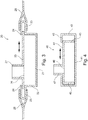
Figure 5 shows a fourth embodiment of adrain 50 according to the invention. The shown cross-section runs overoutlet pipe 51.Drain 50 has abottom surface 52 with aperipheral wall 53.Upper surface bent flange 53 which co-acts withupper surface 54, while on the other side an inward bent flange is provided which co-acts with aflange 56 bent in a U-shape. -
Upper surface inflow opening 57 which is bordered byupright edge 58. - Further arranged in
bottom surface 52 is adischarge opening 59 to which connects a siphon constructed from a dependingwall 60 and anupright wall 61. These twowalls -
Figure 6 shows a fifth embodiment of adrain 70 according to the invention.Drain 70 has abottom surface 71 with anupright edge 72 and an inward directedflange 73. Together withwall part 74,flange 73 forms the upper wall of a tubular housing.Wall parts 74 are held at a distance frombottom surface 71 by means ofspacers 75. - An adjusting
frame 77, as known from for instanceWO 2009/091245 , is further arranged ininflow opening 76 which is formed betweenwall parts 74. - Because
wall parts 74 can slide in horizontal direction relative toflanges 73 and adjustingframe 77 can in addition displace in vertical direction, the upper edge of adjustingframe 77 can thus be fully adapted to a surrounding floor, such as for instance a tiled floor. -
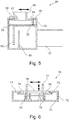
Figure 7 shows a sixth embodiment of adrain 80 according to the invention. Thisdrain 80 has abottom surface 81, an uprightperipheral wall 82 and an inward directedflange 83 on the upper side ofperipheral wall 82. - Together with
sheet parts flange 83 forms the upper surface of a tubular housing.Sheet parts elongate inflow opening 86. - A
tile floor 87 is arranged on top of the tubular housing, whereby only theelongate inflow opening 86 is visible. The tubular housing is arranged in the upper part of a coveringfloor 88 arranged on asystem floor 89. - A siphon 90 connected to an
outlet pipe 91 is further also arranged on the underside ofbottom surface 81. Only this siphon 90 andoutlet pipe 91 are partially recessed intosystem floor 89. -
Figure 8 shows a seventh embodiment of adrain 100. Thisdrain 100 is particularly suitable for placing against a wall. For this purpose drain 100 is provided with abottom surface 101 and aperipheral wall part 102 of the peripheral wall which lies against a wall is higher than theother part 103 of the peripheral wall. - A
horizontal flange 104 is arranged on thehigh part 102. A sealingmembrane 105 and afinishing strip 106 are arranged on this flange. This finishingstrip 106 can slide inward and outward onflange 104, whereby various adjustments can be made to the thickness ofwall tiles 107.Wall tiles 107 are arranged on sealingmembrane 105 andhorizontal flange 104. - A
horizontal flange 108, which together with aseparate sheet part 109 forms the upper surface of a tubular housing, is likewise arranged on thelow part 103 of the peripheral wall. Theseparate sheet part 109 can slide reciprocally so that theelongate inflow opening 110 can be adjusted in the width and can moreover be adapted tofloor tiles 111. - The
separate sheet part 109 has an upright edge which shieldsspace 112 at the corner of the floor tile. The sealing compound arranged here is thus protected from cleaning agents and soap residues by the upright edge.
Claims (9)
- Drain (20; 40; 50; 70; 80; 100) and a surrounding floor (87, 88), which drain (20; 40; 50; 70; 80; 100) comprises a housing with a longitudinal direction, a bottom surface (21; 41; 52; 71; 81; 101) in which a discharge opening (59) is arranged, an upright peripheral edge(22; 42; 53; 72; 82; 102, 103) along the edge of the bottom surface (21; 41; 52; 71; 81; 101), and an elongate opening (26; 46; 57; 76; 86; 110), which elongate opening (26; 46; 57; 76; 86; 110) extends parallel to the longitudinal direction of the housing, the tubular housing being integrated into the surrounding floor (87, 88); and- a siphon (60, 61; 90) arranged on the discharge opening (59) in the bottom surface (21; 41; 52; 71; 81; 101),
characterized in that
the housing is tubular having an upper surface (25; 44; 54; 74; 84; 104), wherein the elongate opening (26; 46; 57; 76; 86; 110) is arranged in the upper surface (25; 44; 54; 74; 84; 104);
wherein the upper edge of the peripheral wall comprises an inward directed horizontal flange (24; 43; 55; 73; 83; 104), which horizontal flange (24; 43; 55; 73; 83; 104) forms together with a separate sheet part (25; 44; 54; 74; 84; 106, 109) the upper wall of the housing; and
wherein the upper layer (14; 88) of the surrounding floor (13, 14; 87, 88) is laid over the tubular housing (2, 3, 4, 8, 9, 10) up to the elongate opening (7; 26; 46; 57; 76; 86; 110). - Drain and a surrounding floor according to claim 1, comprising an upright edge arranged along at least a part of the periphery of the elongate opening in the bottom surface.
- Drain and a surrounding floor as claimed in claim 1 or 2, wherein at least a part of the upright peripheral edge is provided on the upper side with a part folded horizontally outward and an inward folded part connecting thereto, such that the upper side is provided with a horizontal flange of U-shaped cross-section.
- Drain and a surrounding floor as claimed in claim 3, wherein the upper surface is the separate sheet part which protrudes with the peripheral edges into the horizontal flange of U-shaped cross-section.
- Drain and a surrounding floor as claimed in claim 4, wherein the separate sheet part is arranged slidably in the horizontal flange.
- Drain and a surrounding floor as claimed in claim 1, wherein spacers are arranged on the underside of the separate sheet part in order to hold the separate sheet part at a distance from the bottom surface and against the horizontal flange.
- Drain and a surrounding floor as claimed in any of the foregoing claims, wherein a closable inspection opening is arranged in the upper surface above the discharge opening.
- Drain and a surrounding floor as claimed in any of the foregoing claims, wherein the separate sheet part is arranged slidably in the elongate opening.
- Drain and a surrounding floor as claimed in any of the foregoing claims, wherein the upper surface is stepped so that wall tiles can for instance be placed on the highest part.
Priority Applications (1)
| Application Number | Priority Date | Filing Date | Title |
|---|---|---|---|
| PL17205960T PL3309309T3 (en) | 2009-11-23 | 2010-11-23 | Drain comprising a tubular housing and a siphon |
Applications Claiming Priority (2)
| Application Number | Priority Date | Filing Date | Title |
|---|---|---|---|
| NL2003844A NL2003844C2 (en) | 2009-11-23 | 2009-11-23 | DRAIN SINK WITH STOCK ROOM. |
| EP10192221.9A EP2325406B1 (en) | 2009-11-23 | 2010-11-23 | Drain with storage room |
Related Parent Applications (2)
| Application Number | Title | Priority Date | Filing Date |
|---|---|---|---|
| EP10192221.9A Division EP2325406B1 (en) | 2009-11-23 | 2010-11-23 | Drain with storage room |
| EP10192221.9A Division-Into EP2325406B1 (en) | 2009-11-23 | 2010-11-23 | Drain with storage room |
Publications (2)
| Publication Number | Publication Date |
|---|---|
| EP3309309A1 EP3309309A1 (en) | 2018-04-18 |
| EP3309309B1 true EP3309309B1 (en) | 2020-12-23 |
Family
ID=42254178
Family Applications (2)
| Application Number | Title | Priority Date | Filing Date |
|---|---|---|---|
| EP10192221.9A Active EP2325406B1 (en) | 2009-11-23 | 2010-11-23 | Drain with storage room |
| EP17205960.2A Active EP3309309B1 (en) | 2009-11-23 | 2010-11-23 | Drain comprising a tubular housing and a siphon |
Family Applications Before (1)
| Application Number | Title | Priority Date | Filing Date |
|---|---|---|---|
| EP10192221.9A Active EP2325406B1 (en) | 2009-11-23 | 2010-11-23 | Drain with storage room |
Country Status (6)
| Country | Link |
|---|---|
| EP (2) | EP2325406B1 (en) |
| DK (1) | DK3309309T3 (en) |
| ES (2) | ES2660437T3 (en) |
| NL (1) | NL2003844C2 (en) |
| PL (2) | PL2325406T3 (en) |
| TR (1) | TR201802085T4 (en) |
Families Citing this family (2)
| Publication number | Priority date | Publication date | Assignee | Title |
|---|---|---|---|---|
| BE1021904B1 (en) * | 2013-09-13 | 2016-01-26 | Geni*Us Bvba | CONNECTION MEANS FOR CONNECTING A DRAIN PIPE TO A DRAIN OPENING OF A SANITARY INSTALLATION, CONNECTION KIT FORMING THAT CONNECTION MEANS AND SANITARY INSTALLATION WITH A DRAIN OPENING TO WHICH A DRAIN PIPE IS CONNECTED BY SUCH MEANS OF THIS. |
| DE202016104882U1 (en) * | 2016-09-05 | 2016-09-26 | SAXOBOARD Wellness & Duschsysteme GmbH | Drain unit and drainage device for the discharge of water |
Citations (2)
| Publication number | Priority date | Publication date | Assignee | Title |
|---|---|---|---|---|
| GB2311549A (en) * | 1996-03-26 | 1997-10-01 | Elkington Gatic Limited | A slot drain and a pipe for a drainage system |
| EP2319997A1 (en) * | 2009-11-05 | 2011-05-11 | Easy Sanitairy Solutions B.V. | Drain without grating |
Family Cites Families (8)
| Publication number | Priority date | Publication date | Assignee | Title |
|---|---|---|---|---|
| GB2210392B (en) * | 1987-09-30 | 1991-11-06 | Gatic Australia Pty Limited | Improvements relating to drainage grating assemblies |
| DE202005019964U1 (en) * | 2005-12-21 | 2006-03-02 | Kessel Gmbh | drainage system |
| NL1031975C2 (en) * | 2006-06-09 | 2007-12-11 | Easy Sanitairy Solutions Bv | Drainage pit with raised edge. |
| DE202006014745U1 (en) * | 2006-09-22 | 2006-11-23 | Dallmer Gmbh & Co. Kg | Floor drain, e.g. for a shower, has a primary inflow opening and a number of different secondary openings for all the water to run away into the waste pipe from the whole floor surface |
| NL1032706C2 (en) * | 2006-10-19 | 2008-04-22 | Easy Sanitairy Solutions Bv | Adjustable drain. |
| DK200700042A (en) * | 2007-01-11 | 2008-07-12 | Bluecher Metal As | Floor drainage |
| FR2923503A1 (en) * | 2007-11-09 | 2009-05-15 | Farhooman Davoudi | Shower basin device for use in bathroom, has extra-thin evacuation part integrated in its body and possessing low recessed depth of specific centimeter, where barriers and device are formed as single unit |
| NL1034911C2 (en) | 2008-01-14 | 2009-07-15 | Easy Sanitairy Solutions Bv | Drain with adjustable frame. |
-
2009
- 2009-11-23 NL NL2003844A patent/NL2003844C2/en not_active IP Right Cessation
-
2010
- 2010-11-23 ES ES10192221.9T patent/ES2660437T3/en active Active
- 2010-11-23 DK DK17205960.2T patent/DK3309309T3/en active
- 2010-11-23 EP EP10192221.9A patent/EP2325406B1/en active Active
- 2010-11-23 PL PL10192221T patent/PL2325406T3/en unknown
- 2010-11-23 PL PL17205960T patent/PL3309309T3/en unknown
- 2010-11-23 ES ES17205960T patent/ES2843080T3/en active Active
- 2010-11-23 TR TR2018/02085T patent/TR201802085T4/en unknown
- 2010-11-23 EP EP17205960.2A patent/EP3309309B1/en active Active
Patent Citations (2)
| Publication number | Priority date | Publication date | Assignee | Title |
|---|---|---|---|---|
| GB2311549A (en) * | 1996-03-26 | 1997-10-01 | Elkington Gatic Limited | A slot drain and a pipe for a drainage system |
| EP2319997A1 (en) * | 2009-11-05 | 2011-05-11 | Easy Sanitairy Solutions B.V. | Drain without grating |
Also Published As
| Publication number | Publication date |
|---|---|
| EP3309309A1 (en) | 2018-04-18 |
| PL2325406T3 (en) | 2018-05-30 |
| EP2325406A1 (en) | 2011-05-25 |
| NL2003844C2 (en) | 2011-05-24 |
| TR201802085T4 (en) | 2018-03-21 |
| EP2325406B1 (en) | 2018-01-24 |
| ES2660437T3 (en) | 2018-03-22 |
| DK3309309T3 (en) | 2021-01-25 |
| ES2843080T3 (en) | 2021-07-15 |
| PL3309309T3 (en) | 2021-05-31 |
Similar Documents
| Publication | Publication Date | Title |
|---|---|---|
| US8161582B2 (en) | Shower enclosure and base | |
| EP2405062B1 (en) | Showerdrain with insert | |
| EP3309309B1 (en) | Drain comprising a tubular housing and a siphon | |
| RU2410501C1 (en) | Drain device | |
| JP2006328772A (en) | Bathroom unit | |
| DE102010015856B4 (en) | floor element | |
| EP2466023B1 (en) | Flat plate gutter | |
| US10478039B2 (en) | Undercounter appliance drain pan | |
| EP2287410B1 (en) | Siphon accessible to plumbing snake via feed opening | |
| NL2001312C2 (en) | Drainage channel for floor drain, has malodor impermeable portion of cover joined to lower vertical wall of water seal for odor trap | |
| EP1460186B2 (en) | Triangular drainage | |
| EP2216449B1 (en) | Drain with inspection hole | |
| US10264925B2 (en) | Shower pan and bathtub with curved outer edge and elevated threshold | |
| EP2085528A1 (en) | Shower drain | |
| EP3540138A1 (en) | Drain | |
| US9782045B2 (en) | Under mud shower pan with seat | |
| JP2009287175A (en) | Wash place pan | |
| GB2382769A (en) | Shower tray and integral trap assembly | |
| US9756987B2 (en) | Under mud shower pan with seat | |
| KR101415317B1 (en) | The height control is possible double trap stratiform plumbing fixtures | |
| EP3971353A1 (en) | Floor gully assembly comprising floor gully and water trap | |
| EP2302143B1 (en) | Gutter drain | |
| CA2970487C (en) | Under mud shower pan with seat | |
| JP3222116B2 (en) | Drain basin bottom structure | |
| CN105780911A (en) | A Method Of Installing A Plumbing Flange, And A Transportable Base |
Legal Events
| Date | Code | Title | Description |
|---|---|---|---|
| PUAI | Public reference made under article 153(3) epc to a published international application that has entered the european phase |
Free format text: ORIGINAL CODE: 0009012 |
|
| STAA | Information on the status of an ep patent application or granted ep patent |
Free format text: STATUS: THE APPLICATION HAS BEEN PUBLISHED |
|
| AC | Divisional application: reference to earlier application |
Ref document number: 2325406 Country of ref document: EP Kind code of ref document: P |
|
| AK | Designated contracting states |
Kind code of ref document: A1 Designated state(s): AL AT BE BG CH CY CZ DE DK EE ES FI FR GB GR HR HU IE IS IT LI LT LU LV MC MK MT NL NO PL PT RO RS SE SI SK SM TR |
|
| STAA | Information on the status of an ep patent application or granted ep patent |
Free format text: STATUS: REQUEST FOR EXAMINATION WAS MADE |
|
| 17P | Request for examination filed |
Effective date: 20181011 |
|
| RBV | Designated contracting states (corrected) |
Designated state(s): AL AT BE BG CH CY CZ DE DK EE ES FI FR GB GR HR HU IE IS IT LI LT LU LV MC MK MT NL NO PL PT RO RS SE SI SK SM TR |
|
| STAA | Information on the status of an ep patent application or granted ep patent |
Free format text: STATUS: EXAMINATION IS IN PROGRESS |
|
| 17Q | First examination report despatched |
Effective date: 20200110 |
|
| GRAP | Despatch of communication of intention to grant a patent |
Free format text: ORIGINAL CODE: EPIDOSNIGR1 |
|
| STAA | Information on the status of an ep patent application or granted ep patent |
Free format text: STATUS: GRANT OF PATENT IS INTENDED |
|
| INTG | Intention to grant announced |
Effective date: 20200626 |
|
| GRAS | Grant fee paid |
Free format text: ORIGINAL CODE: EPIDOSNIGR3 |
|
| GRAA | (expected) grant |
Free format text: ORIGINAL CODE: 0009210 |
|
| STAA | Information on the status of an ep patent application or granted ep patent |
Free format text: STATUS: THE PATENT HAS BEEN GRANTED |
|
| AC | Divisional application: reference to earlier application |
Ref document number: 2325406 Country of ref document: EP Kind code of ref document: P |
|
| AK | Designated contracting states |
Kind code of ref document: B1 Designated state(s): AL AT BE BG CH CY CZ DE DK EE ES FI FR GB GR HR HU IE IS IT LI LT LU LV MC MK MT NL NO PL PT RO RS SE SI SK SM TR |
|
| REG | Reference to a national code |
Ref country code: GB Ref legal event code: FG4D |
|
| REG | Reference to a national code |
Ref country code: DE Ref legal event code: R096 Ref document number: 602010066234 Country of ref document: DE |
|
| REG | Reference to a national code |
Ref country code: AT Ref legal event code: REF Ref document number: 1347864 Country of ref document: AT Kind code of ref document: T Effective date: 20210115 Ref country code: CH Ref legal event code: NV Representative=s name: VALIPAT S.A. C/O BOVARD SA NEUCHATEL, CH |
|
| REG | Reference to a national code |
Ref country code: IE Ref legal event code: FG4D |
|
| REG | Reference to a national code |
Ref country code: DK Ref legal event code: T3 Effective date: 20210119 |
|
| REG | Reference to a national code |
Ref country code: NL Ref legal event code: FP |
|
| REG | Reference to a national code |
Ref country code: SE Ref legal event code: TRGR |
|
| REG | Reference to a national code |
Ref country code: NO Ref legal event code: T2 Effective date: 20201223 |
|
| PG25 | Lapsed in a contracting state [announced via postgrant information from national office to epo] |
Ref country code: FI Free format text: LAPSE BECAUSE OF FAILURE TO SUBMIT A TRANSLATION OF THE DESCRIPTION OR TO PAY THE FEE WITHIN THE PRESCRIBED TIME-LIMIT Effective date: 20201223 Ref country code: GR Free format text: LAPSE BECAUSE OF FAILURE TO SUBMIT A TRANSLATION OF THE DESCRIPTION OR TO PAY THE FEE WITHIN THE PRESCRIBED TIME-LIMIT Effective date: 20210324 Ref country code: RS Free format text: LAPSE BECAUSE OF FAILURE TO SUBMIT A TRANSLATION OF THE DESCRIPTION OR TO PAY THE FEE WITHIN THE PRESCRIBED TIME-LIMIT Effective date: 20201223 |
|
| PG25 | Lapsed in a contracting state [announced via postgrant information from national office to epo] |
Ref country code: BG Free format text: LAPSE BECAUSE OF FAILURE TO SUBMIT A TRANSLATION OF THE DESCRIPTION OR TO PAY THE FEE WITHIN THE PRESCRIBED TIME-LIMIT Effective date: 20210323 Ref country code: LV Free format text: LAPSE BECAUSE OF FAILURE TO SUBMIT A TRANSLATION OF THE DESCRIPTION OR TO PAY THE FEE WITHIN THE PRESCRIBED TIME-LIMIT Effective date: 20201223 |
|
| PG25 | Lapsed in a contracting state [announced via postgrant information from national office to epo] |
Ref country code: HR Free format text: LAPSE BECAUSE OF FAILURE TO SUBMIT A TRANSLATION OF THE DESCRIPTION OR TO PAY THE FEE WITHIN THE PRESCRIBED TIME-LIMIT Effective date: 20201223 |
|
| REG | Reference to a national code |
Ref country code: LT Ref legal event code: MG9D |
|
| REG | Reference to a national code |
Ref country code: ES Ref legal event code: FG2A Ref document number: 2843080 Country of ref document: ES Kind code of ref document: T3 Effective date: 20210715 |
|
| PG25 | Lapsed in a contracting state [announced via postgrant information from national office to epo] |
Ref country code: SK Free format text: LAPSE BECAUSE OF FAILURE TO SUBMIT A TRANSLATION OF THE DESCRIPTION OR TO PAY THE FEE WITHIN THE PRESCRIBED TIME-LIMIT Effective date: 20201223 Ref country code: PT Free format text: LAPSE BECAUSE OF FAILURE TO SUBMIT A TRANSLATION OF THE DESCRIPTION OR TO PAY THE FEE WITHIN THE PRESCRIBED TIME-LIMIT Effective date: 20210423 Ref country code: RO Free format text: LAPSE BECAUSE OF FAILURE TO SUBMIT A TRANSLATION OF THE DESCRIPTION OR TO PAY THE FEE WITHIN THE PRESCRIBED TIME-LIMIT Effective date: 20201223 Ref country code: SM Free format text: LAPSE BECAUSE OF FAILURE TO SUBMIT A TRANSLATION OF THE DESCRIPTION OR TO PAY THE FEE WITHIN THE PRESCRIBED TIME-LIMIT Effective date: 20201223 Ref country code: EE Free format text: LAPSE BECAUSE OF FAILURE TO SUBMIT A TRANSLATION OF THE DESCRIPTION OR TO PAY THE FEE WITHIN THE PRESCRIBED TIME-LIMIT Effective date: 20201223 Ref country code: LT Free format text: LAPSE BECAUSE OF FAILURE TO SUBMIT A TRANSLATION OF THE DESCRIPTION OR TO PAY THE FEE WITHIN THE PRESCRIBED TIME-LIMIT Effective date: 20201223 |
|
| REG | Reference to a national code |
Ref country code: DE Ref legal event code: R097 Ref document number: 602010066234 Country of ref document: DE |
|
| PG25 | Lapsed in a contracting state [announced via postgrant information from national office to epo] |
Ref country code: IS Free format text: LAPSE BECAUSE OF FAILURE TO SUBMIT A TRANSLATION OF THE DESCRIPTION OR TO PAY THE FEE WITHIN THE PRESCRIBED TIME-LIMIT Effective date: 20210423 |
|
| PG25 | Lapsed in a contracting state [announced via postgrant information from national office to epo] |
Ref country code: AL Free format text: LAPSE BECAUSE OF FAILURE TO SUBMIT A TRANSLATION OF THE DESCRIPTION OR TO PAY THE FEE WITHIN THE PRESCRIBED TIME-LIMIT Effective date: 20201223 |
|
| PLBE | No opposition filed within time limit |
Free format text: ORIGINAL CODE: 0009261 |
|
| STAA | Information on the status of an ep patent application or granted ep patent |
Free format text: STATUS: NO OPPOSITION FILED WITHIN TIME LIMIT |
|
| 26N | No opposition filed |
Effective date: 20210924 |
|
| PGFP | Annual fee paid to national office [announced via postgrant information from national office to epo] |
Ref country code: AT Payment date: 20211122 Year of fee payment: 12 Ref country code: CZ Payment date: 20211026 Year of fee payment: 12 Ref country code: GB Payment date: 20211118 Year of fee payment: 12 Ref country code: TR Payment date: 20211109 Year of fee payment: 12 Ref country code: NO Payment date: 20211119 Year of fee payment: 12 Ref country code: SE Payment date: 20211117 Year of fee payment: 12 Ref country code: ES Payment date: 20211209 Year of fee payment: 12 Ref country code: DK Payment date: 20211117 Year of fee payment: 12 Ref country code: FR Payment date: 20211115 Year of fee payment: 12 |
|
| PG25 | Lapsed in a contracting state [announced via postgrant information from national office to epo] |
Ref country code: SI Free format text: LAPSE BECAUSE OF FAILURE TO SUBMIT A TRANSLATION OF THE DESCRIPTION OR TO PAY THE FEE WITHIN THE PRESCRIBED TIME-LIMIT Effective date: 20201223 |
|
| PGFP | Annual fee paid to national office [announced via postgrant information from national office to epo] |
Ref country code: IT Payment date: 20211118 Year of fee payment: 12 Ref country code: BE Payment date: 20211118 Year of fee payment: 12 |
|
| PGFP | Annual fee paid to national office [announced via postgrant information from national office to epo] |
Ref country code: PL Payment date: 20211108 Year of fee payment: 12 |
|
| PG25 | Lapsed in a contracting state [announced via postgrant information from national office to epo] |
Ref country code: MC Free format text: LAPSE BECAUSE OF FAILURE TO SUBMIT A TRANSLATION OF THE DESCRIPTION OR TO PAY THE FEE WITHIN THE PRESCRIBED TIME-LIMIT Effective date: 20201223 |
|
| PG25 | Lapsed in a contracting state [announced via postgrant information from national office to epo] |
Ref country code: LU Free format text: LAPSE BECAUSE OF NON-PAYMENT OF DUE FEES Effective date: 20211123 |
|
| REG | Reference to a national code |
Ref country code: AT Ref legal event code: UEP Ref document number: 1347864 Country of ref document: AT Kind code of ref document: T Effective date: 20201223 |
|
| PG25 | Lapsed in a contracting state [announced via postgrant information from national office to epo] |
Ref country code: IE Free format text: LAPSE BECAUSE OF NON-PAYMENT OF DUE FEES Effective date: 20211123 |
|
| PG25 | Lapsed in a contracting state [announced via postgrant information from national office to epo] |
Ref country code: HU Free format text: LAPSE BECAUSE OF FAILURE TO SUBMIT A TRANSLATION OF THE DESCRIPTION OR TO PAY THE FEE WITHIN THE PRESCRIBED TIME-LIMIT; INVALID AB INITIO Effective date: 20101123 Ref country code: CY Free format text: LAPSE BECAUSE OF FAILURE TO SUBMIT A TRANSLATION OF THE DESCRIPTION OR TO PAY THE FEE WITHIN THE PRESCRIBED TIME-LIMIT Effective date: 20201223 |
|
| REG | Reference to a national code |
Ref country code: DK Ref legal event code: EBP Effective date: 20221130 |
|
| REG | Reference to a national code |
Ref country code: NO Ref legal event code: MMEP |
|
| REG | Reference to a national code |
Ref country code: SE Ref legal event code: EUG |
|
| REG | Reference to a national code |
Ref country code: AT Ref legal event code: MM01 Ref document number: 1347864 Country of ref document: AT Kind code of ref document: T Effective date: 20221123 |
|
| GBPC | Gb: european patent ceased through non-payment of renewal fee |
Effective date: 20221123 |
|
| REG | Reference to a national code |
Ref country code: BE Ref legal event code: MM Effective date: 20221130 |
|
| PG25 | Lapsed in a contracting state [announced via postgrant information from national office to epo] |
Ref country code: NO Free format text: LAPSE BECAUSE OF NON-PAYMENT OF DUE FEES Effective date: 20221130 Ref country code: CZ Free format text: LAPSE BECAUSE OF NON-PAYMENT OF DUE FEES Effective date: 20221123 Ref country code: AT Free format text: LAPSE BECAUSE OF NON-PAYMENT OF DUE FEES Effective date: 20221123 |
|
| PG25 | Lapsed in a contracting state [announced via postgrant information from national office to epo] |
Ref country code: SE Free format text: LAPSE BECAUSE OF NON-PAYMENT OF DUE FEES Effective date: 20221124 |
|
| P01 | Opt-out of the competence of the unified patent court (upc) registered |
Effective date: 20230831 |
|
| PG25 | Lapsed in a contracting state [announced via postgrant information from national office to epo] |
Ref country code: IT Free format text: LAPSE BECAUSE OF NON-PAYMENT OF DUE FEES Effective date: 20221123 Ref country code: GB Free format text: LAPSE BECAUSE OF NON-PAYMENT OF DUE FEES Effective date: 20221123 Ref country code: DK Free format text: LAPSE BECAUSE OF NON-PAYMENT OF DUE FEES Effective date: 20221130 |
|
| PG25 | Lapsed in a contracting state [announced via postgrant information from national office to epo] |
Ref country code: FR Free format text: LAPSE BECAUSE OF NON-PAYMENT OF DUE FEES Effective date: 20221130 Ref country code: BE Free format text: LAPSE BECAUSE OF NON-PAYMENT OF DUE FEES Effective date: 20221130 |
|
| PGFP | Annual fee paid to national office [announced via postgrant information from national office to epo] |
Ref country code: NL Payment date: 20231124 Year of fee payment: 14 |
|
| REG | Reference to a national code |
Ref country code: ES Ref legal event code: FD2A Effective date: 20240102 |
|
| PG25 | Lapsed in a contracting state [announced via postgrant information from national office to epo] |
Ref country code: ES Free format text: LAPSE BECAUSE OF NON-PAYMENT OF DUE FEES Effective date: 20221124 |
|
| PG25 | Lapsed in a contracting state [announced via postgrant information from national office to epo] |
Ref country code: ES Free format text: LAPSE BECAUSE OF NON-PAYMENT OF DUE FEES Effective date: 20221124 |
|
| PGFP | Annual fee paid to national office [announced via postgrant information from national office to epo] |
Ref country code: DE Payment date: 20231127 Year of fee payment: 14 Ref country code: CH Payment date: 20231202 Year of fee payment: 14 |