EP3307967B1 - Gittermaststruktur sowie verfahren zur standfestigkeitserhöhung an eine gittermaststruktur - Google Patents
Gittermaststruktur sowie verfahren zur standfestigkeitserhöhung an eine gittermaststruktur Download PDFInfo
- Publication number
- EP3307967B1 EP3307967B1 EP16726079.3A EP16726079A EP3307967B1 EP 3307967 B1 EP3307967 B1 EP 3307967B1 EP 16726079 A EP16726079 A EP 16726079A EP 3307967 B1 EP3307967 B1 EP 3307967B1
- Authority
- EP
- European Patent Office
- Prior art keywords
- strut
- hose
- cross
- support
- steel
- Prior art date
- Legal status (The legal status is an assumption and is not a legal conclusion. Google has not performed a legal analysis and makes no representation as to the accuracy of the status listed.)
- Active
Links
Images

Classifications
-
- E—FIXED CONSTRUCTIONS
- E04—BUILDING
- E04H—BUILDINGS OR LIKE STRUCTURES FOR PARTICULAR PURPOSES; SWIMMING OR SPLASH BATHS OR POOLS; MASTS; FENCING; TENTS OR CANOPIES, IN GENERAL
- E04H12/00—Towers; Masts or poles; Chimney stacks; Water-towers; Methods of erecting such structures
- E04H12/02—Structures made of specified materials
- E04H12/08—Structures made of specified materials of metal
- E04H12/10—Truss-like structures
-
- E—FIXED CONSTRUCTIONS
- E04—BUILDING
- E04C—STRUCTURAL ELEMENTS; BUILDING MATERIALS
- E04C5/00—Reinforcing elements, e.g. for concrete; Auxiliary elements therefor
- E04C5/07—Reinforcing elements of material other than metal, e.g. of glass, of plastics, or not exclusively made of metal
-
- E—FIXED CONSTRUCTIONS
- E04—BUILDING
- E04H—BUILDINGS OR LIKE STRUCTURES FOR PARTICULAR PURPOSES; SWIMMING OR SPLASH BATHS OR POOLS; MASTS; FENCING; TENTS OR CANOPIES, IN GENERAL
- E04H12/00—Towers; Masts or poles; Chimney stacks; Water-towers; Methods of erecting such structures
- E04H12/16—Prestressed structures
Definitions
- the invention relates to a lattice mast structure comprising supports designed as steel profiles and extending between the supports diagonal struts or cross struts or diagonal struts and cross struts.
- the invention further relates to a method for increasing the stability of such a lattice mast structure as a subsequent upgrade.
- Lattice mast structures of the aforementioned type are open steel truss structures with angle profiles or round profiles on bridges, in the form of pylons or electricity pylons.
- Such lattice mast structures have the advantage that they are particularly lightweight and easy to build.
- the lattice mast structure consists of angle profiles, the individual profile struts are relatively easy to connect to each other, for example by riveting, welding or screwing.
- Lattice mast structures are mainly used as lattice towers for receiving electrical transmission lines.
- Lattice masts are usually constructed of a series of superimposed structural elements, each step forming a truss structure having three or more trapezoidal truss panels, each consisting of struts braced together.
- the supports are designed as angle profiles, these connecting struts in the form of cross struts or diagonal struts can also be partially formed as angle profiles, in part, as tab profiles.
- the dimensioning of the truss structure forming components on the one hand depends on the free buckling length of the individual elements in this prevailing Zuwood or compressive stress and on the other hand by the interaction of longitudinal forces and lateral forces that are registered for example by wind loads in the building.
- bracing systems For the stabilization of lattice structures or framework structures of the type described above, numerous bracing systems are known which are optimized with regard to the arrangement of the framework struts and with regard to the total weight of the lattice structure. Such a system is for example in the GB 675,859 A described.
- lattice towers have to accommodate additional lines on their mast booms, because, for example, in a power grid, a greater electrical power must be provided.
- EP2381052 A2 describes a tower for use with a wind turbine.
- DE19939799 A1 describes a method and arrangement for the rehabilitation or reinforcement of columns.
- US 2010/218708 A1 describes a method of reinforcing structures against explosions.
- JP09217419 describes a support tower and method for reinforcing its grid structure.
- WO 2009/098528 describes a lattice tower and method for its reinforcement by filling concrete in its support legs.
- WO 2005/026450 and JP 2006028902 describe further various methods for reinforcing bars and lattice mast structures.
- the invention is therefore based on the object to provide an ertriche lattice boom structure and a method for upgrading conventional lattice structures.
- the object is achieved with the features of claim 1 and with the features of the independent claim 6.
- Preferred variants of the invention will become apparent from the dependent claims.
- Under a lattice mast structure in the context of the present invention is an open framework structure to understand the struts are not provided with infills.
- lattice mast structure are, for example, lattice towers for receiving electrical power lines, pylons, bridge piers or the like into consideration, which are to be trained in the extension direction of designed as columns steel profiles in terms of the desired buckling stability.
- a lattice mast structure comprising supports formed as steel profiles and extending between the struts diagonal struts or cross struts or diagonal struts and cross struts, said lattice mast structure comprises at least one reinforcing rod, wherein the reinforcing rod in the longitudinal direction in a support or a Cross bar or a diagonal strut, the reinforcing rod in the course of the support or the crossbar (6) or the diagonal strut follows, the reinforcing rod is connected at at least two spaced locations with the support or the crossbar (6) or the diagonal strut, so that the reinforcing rod with respect to the power flow through the support or the cross member or the diagonal strut forms a structural composite with this and the reinforcing rod is formed as at least two-part component, that as preferably two-part structure composite of e is formed inem predominantly tensile forces transmitting element and a predominantly compressive forces transmitting element.
- a steel profile in the sense of the present invention may be understood to mean a round profile or also an angle profile.
- an angle profile means, for example, a T-profile, L-profile, I-profile, Z-profile, U-profile, C-profile or the like.
- the lattice mast structure in the sense of the present invention can be designed, for example, as a steel truss structure with three or four supports, in particular supports, which can converge in the direction of a mast top. It can each two columns together with cross struts trapezoidal fields form a mast level.
- Several mast steps may extend in height from a base of the lattice mast to its mast top.
- the lattice mast may comprise, for example, mast arms arranged symmetrically to the supports, which in turn have a corresponding framework structure and taper from a base to its distal end.
- a predominantly tensile forces transmitting element in the context of the present invention is an element to understand that can transmit greater tensile forces than compressive forces.
- this is understood to mean an element that can transmit more than twice as high tensile forces as compressive forces.
- a compressive force transmitting element is an element to understand that can transmit more compressive forces than tensile forces, preferably more than twice as high compressive forces as tensile forces.
- the tensile force transmitting member is preferably selected from a group comprising ropes, fibers, scrims, fabrics or braids of steel, glass fibers or carbon fibers.
- the compressive force transmitting element is preferably selected from a group comprising concrete, polymer concrete, mineral potting compounds and thermoplastic non-foamed and thermoplastic and foamed potting compounds.
- the tensile forces transmitting element may be formed for example in the form of one or more ropes or in the form of a tube.
- the basic idea of the invention can be seen in that by means of one or more reinforcing rods on at least one, preferably on several supports by a structural composite of the reinforcing rod with the support, the free buckling length of the respective support and thus also their load in the longitudinal direction is increased.
- each support may be provided, for example, each extending over the full length of the support reinforcing rod, which is firmly connected at several points with distance from each other with the support.
- a plurality of reinforcing rods may be attached in sections over the length of a support.
- the formation of the reinforcing rod as at least two-part composite component has the advantage that this assembly is greatly simplified.
- the tensile forces transmitting element may be formed as a bendable element, which is easy to install.
- the compressive force-transmitting element may for example consist of a cured potting compound, whereby also the handling of the reinforcing rod for the purpose of assembly is greatly simplified.
- the reinforcing rod comprises a tension member made of steel and a steel body made of a hardened potting compound.
- the reinforcing rod comprises one or more steel cables which are embedded in a shell made of a hardened potting compound.
- a parallel arrangement of one or more steel cables and a body of a cured potting compound is possible. These can be connected to each other in sections.
- the curable potting compound can in this case be included for example in a flexible textile hose as a laying aid and lost formwork for the potting compound.
- the reinforcing rod has a sheath of a tensile steel fabric or a steel-reinforced textile fabric or a steel mesh and a soul of a cured potting compound.
- the reinforcing bar is in each case connected to the corner support in the region of nodal points of the lattice mast structure.
- the tensile forces transmitting element is biased. This can for example be laid from a mast top of the lattice mast structure to a mast base or to a mast foundation or a mast base and be biased between the attachment points. By subsequent casting or pressing the tensile forces transmitting element with the curable potting compound, the tensile stress may have been frozen.
- the reinforcing rod is connected to a foundation of the lattice mast.
- a predominantly tensile forces transmitting element is provided in the manner described above.
- the lateral surface does not have to be completely closed, so that a partial penetration of the potting compound through the lateral surface of the hose is possible.
- a textile hose with a steel reinforcement is used as the hose, wherein the steel reinforcement of the textile hose forms the element transmitting the tensile forces or the tensile element.
- the reinforcement can optionally also be formed from carbon fibers, textile fibers, glass fibers or similar materials.
- the hose encloses at least one steel cable, wherein the steel cable at least at its two ends to the support or the Cross strut or the diagonal strut is attached.
- the hose and / or the tension-resistant element are each connected to the supports in the region of nodal points of the lattice structure.
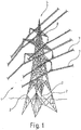
- the lattice mast 1 as a lattice mast structure according to the present invention is in FIG. 1 designed as a conventional, open steel framework construction with four supports 2, which are formed in the present case as open angle sections 3 with two equal legs 4 and an angle peak 10.
- the lattice mast 1 is described here, for example, as a truss structure with angle profiles, in particular as an open steel truss structure.
- lattice mast structures and bridge structures, pylons or similar structures can be provided as truss structure.
- the lattice mast takes in the field of its establishment a relatively large footprint on the four supports 2 of the lattice mast 1 converge towards a mast top 5.
- two supports 2 together with cross struts 6 trapezoidal fields a mast level.
- Each mast step is described in total by four trapezoidal fields, several mast steps extend in height from the base of the lattice mast 1 to the mast top 5.
- the individual fields of the steps of the lattice mast are formed as truss structures with diagonal struts 9, depending on the amount of transverse load of Lattice mast as pressure bars or tension bars act.
- the leaning towards the mast top 5 form of the lattice mast 1 is due to the expected bending stress of the lattice mast 1 due to wind load and due to lines 7.
- the lines 7 are suspended in a known manner to mast brackets 8.
- the geometry of the mast boom is adapted to the expected bending moment course due to the weight of the lines 7.
- FIG. 2 showing a sectional view of a support 2 of the lattice mast 1 as an angle section 3 in the sense of the present application.
- the section is shown as a cross section at the height of a node of the truss structure of the lattice mast 1.
- two transverse struts 6 are fastened to adjacent supports 2 on the legs 4 of the angle profile 3.
- the angle vertex 10 of the angle section 3 of the support 2 points outwards of the mast cross-section enclosed by the supports 2.
- 11 crampons are referred to the supports 2.
- the reinforcing rods 12 are attached to the legs 4 of the angle profile 3 outside the angle apex 10 adjacent, which are formed according to the invention as a two-part composite component.
- the reinforcing rods 12 comprise a steel braided sheath, which is laid as a continuous hose on the respective support 2 of the unspecified foundation of the lattice mast 1 to the mast top 5, and in each case in the region of the nodes of the truss structure, that is in the region of the support 2 connected crossbars 6 is connected to the support 2.
- the connection can be provided for example by means not shown clamps, with the supports 2 or welded to the angle profiles 3 of the supports 2.
- the reinforcing bars 12 further comprise a core of a hardened potting compound that has been pressed from below into the steel fabric tube.
- the finished and cured reinforcing rods 12 form a structural reinforcement of the angle sections 3 and thus an increase in their load and their free buckling length.
Description
- Die Erfindung betrifft eine Gittermaststruktur umfassend als Stahlprofile ausgebildete Stützen und sich zwischen den Stützen erstreckenden Diagonalstreben oder Querstreben oder Diagonalstreben und Querstreben.
- Die Erfindung betrifft weiterhin ein Verfahren zur Standfestigkeitserhöhung an eine solche Gittermaststruktur als nachträgliche Ertüchtigung.
- Gittermaststrukturen der vorbezeichneten Art sind offene Stahlfachwerkbauwerke mit Winkelprofilen oder Rundprofilen an Brücken, in Form von Pylonen oder Stromleitungsmasten. Derartige Gittermaststrukturen besitzen den Vorzug, dass sie besonders leichgewichtig und leicht aufzubauen sind. Insbesondere wenn die Gittermaststruktur aus Winkelprofilen besteht, sind die einzelnen Profilstreben verhältnismäßig leicht aneinander anschließbar, beispielsweise durch Nieten, Schweißen oder Verschrauben.
- Gittermaststrukturen finden überwiegend als Gittermasten zur Aufnahme elektrischer Überlandleitungen Anwendung. Gittermasten sind üblicherweise aus einer Reihe von übereinander angeordneten Strukturelementen aufgebaut, wobei jede Stufe eine Fachwerkstruktur bildet, die drei oder mehr trapezförmige Fachwerkfelder aufweist, die jeweils aus miteinander verstrebten Stützen bestehen. Die Stützen sind als Winkelprofile ausgebildet, die diese verbindenden Streben in Form von Querstreben oder Diagonalstreben können ebenfalls teilweise als Winkelprofile, teilweise auch als Laschenprofile ausgebildet sein.
- Die Gestaltung solcher Fachwerkstrukturen ordnet sich in der Regel den Anforderungen an die Traglast und an die auf das Bauwerk einwirkende Windlast unter. Weiterhin sind für die Auslegung die Kräfte aus Eigengewicht, Abspannung, Eis und Temperatur zu berücksichtigen.
- Die Dimensionierung der die Fachwerkstruktur bildenden Bauelemente ist einerseits von der freien Knicklänge der einzelnen Elemente, der in diesen herrschenden Zuspannung oder Druckspannung und andererseits von dem Zusammenwirken von Längskräften und seitigen Kräften abhängig, die beispielsweise durch Windlasten in das Bauwerk eingetragen werden.
- Zur Stabilisierung von Gitterbauwerken oder Fachwerkstrukturen der zuvor beschriebenen Art sind zahlreiche Verstrebungssysteme bekannt, die hinsichtlich der Anordnung der Fachwerkstreben und im Hinblick auf das Gesamtgewicht der Gitterstruktur optimiert sind. Ein solches System ist beispielsweise in der
GB 675,859 A - Bei der Erstellung von neuen Gittermasten beziehungsweise Gittermaststrukturen ist in der Regel die optimale Auslegung der Struktur für eine zu erwartende Windlast und Traglast in Bezug auf eine Gewichtsoptimierung verhältnismäßig unproblematisch.
- Beispielsweise bei bestehenden Gittermasten für elektrische Überlandleitungen ist es von Zeit zu Zeit gegebenenfalls erforderlich, Teile der Konstruktion auszubessern und/oder zu erneuern. Dies erfordert unter Umständen neue Standfestigkeitsnachweise. Bestehende Anlagen erfüllen erhöhte Standfestigkeitsanforderungen unter Umständen nicht, insbesondere auch wegen erhöhter Lastanforderungen oder wegen einer über eine längere Standzeit zu erwartende Strukturschwächung.
- Manchmal müssen Gittermasten an ihren Mastauslegern zusätzliche Leitungen aufnehmen, weil beispielsweise in einem elektrischen Stromnetz eine größere elektrische Leistung bereitgestellt werden muss.
- In solchen Fällen ist eine Ertüchtigung der bestehenden Gittermasten erforderlich, insbesondere, wenn die freie Knicklänge der Stahlprofile nicht für eine erhöhte Traglast ausgelegt ist oder der Querschnitt als solcher nicht genügend Tragfähigkeit aufweist.
EP2381052 A2 beschreibt einen Stützturm zur Verwendung mit einer Windturbine.DE19939799 A1 beschreibt ein Verfahren und Anordnung zur Sanierung bzw. Verstärkung von Stützen.US 2010/218708 A1 beschreibt eine Verfahren zum Verstärken von Strukturen gegen Explosionen.JP09217419 WO 2009/098528 beschreibt einen Gitterturm und Verfahren zu dessen Verstärkung durch Einfüllen von Beton in dessen Stützbeine.US 2013/0014467 ,WO 2005/026450 undJP 2006028902 - Der Erfindung liegt daher die Aufgabe zugrunde, eine ertüchtige Gittermaststruktur sowie ein Verfahren zur Ertüchtigung herkömmlicher Gittermaststrukturen bereitzustellen. Die Aufgabe wird gelöst mit den Merkmalen des Anspruchs 1 sowie mit den Merkmalen des nebengeordneten Anspruchs 6. Bevorzugte Varianten der Erfindung ergeben sich jeweils aus den Unteransprüchen. Unter einer Gittermaststruktur im Sinne der vorliegenden Erfindung ist eine offene Fachwerkstruktur zu verstehen, deren Streben nicht mit Ausfachungen versehen sind.
- Als Gittermaststruktur kommen beispielsweise Gittermasten zur Aufnahme elektrischer Überlandleitungen, Pylone, Brückenpfeiler oder dergleichen in Betracht, die in Erstreckungsrichtung von als Stützen ausgebildeten Stahlprofilen hinsichtlich der gewünschten Knickstabilität zu ertüchtigen sind.
- Nach einem Gesichtspunkt der Erfindung ist eine Gittermaststruktur umfassend Stützen, die als Stahlprofile ausgebildet sind und sich zwischen den Stützen erstreckende Diagonalstreben oder Querstreben oder Diagonalstreben und Querstreben vorgesehen, wobei die Gittermaststruktur wenigstens einen Verstärkungsstab umfasst, wobei der Verstärkungsstab sich in Längsrichtung in einer Stütze oder einer Querstrebe oder einer Diagonalstrebe erstreckt, der Verstärkungsstab im Verlauf der Stütze oder der Querstrebe (6) oder der Diagonalstrebe folgt, der Verstärkungsstab an wenigstens zwei voneinander abliegenden Stellen mit der Stütze oder der Querstrebe (6) oder der Diagonalstrebe verbunden ist, so dass der Verstärkungsstab hinsichtlich des Kraftflusses durch die Stütze oder die Querstrebe oder die Diagonalstrebe mit dieser einen Strukturverbund bildet und der Verstärkungsstab als wenigstens zweiteiliges Bauteil ausgebildet ist, dass als vorzugsweise zweiteiliger Strukturverbund aus einem überwiegend Zugkräfte übertragenden Element und einem überwiegend Druckkräfte übertragenden Element ausgebildet ist.
- Unter einem Stahlprofil im Sinne der vorliegenden Erfindung kann ein Rundprofil oder auch ein Winkelprofil zu verstehen sein.
- Unter einem Winkelprofil im Sinne der vorliegenden Erfindung ist beispielsweise ein T-Profil, L-Profil, I-Profil, Z-Profil, U-Profil, C-Profil oder dergleichen zu verstehen.
- Die Gittermaststruktur im Sinne der vorliegenden Erfindung kann beispielsweise als Stahlfachwerkstruktur mit drei oder vier Stützen insbesondere Stützen, ausgebildet sein, die in Richtung einer Mastspitze konvergieren können. Dabei können jeweils zwei Stützen zusammen mit Querstreben trapezförmige Felder einer Maststufe bilden. Mehre Maststufen können sich der Höhe nach von einer Basis des Gittermastes zu dessen Mastspitze erstrecken. Der Gittermast kann beispielsweise symmetrisch zu den Stützen angeordnete Mastausleger aufweisen, die ihrerseits eine entsprechende Fachwerkstruktur aufweisen und sich von einer Basis zu ihren abliegenden Ende verjüngen.
- Unter einem überwiegend Zugkräfte übertragenden Element im Sinne der vorliegenden Erfindung ist ein Element zu verstehen, dass größere Zugkräfte als Druckkräfte übertragen kann. Vorzugsweise ist darunter ein Element zu verstehen, dass mehr als doppelt so hohe Zugkräfte als Druckkräfte übertragen kann.
- Unter einem Druckkräfte übertragenden Element im Sinne der vorliegenden Erfindung ist ein Element zu verstehen, dass mehr Druckkräfte als Zugkräfte übertragen kann, vorzugsweise mehr als doppelt so hohe Druckkräfte als Zugkräfte.
- Das Zugkräfte übertragende Element ist vorzugsweise ausgewählt aus einer Gruppe umfassend Seile, Fasern, Gelege, Gewebe oder Geflechte aus Stahl, Glasfasern oder Kohlefasern. Das Druckkräfte übertragende Element ist vorzugsweise ausgewählt aus einer Gruppe umfassend Beton, Polymerbeton, mineralische Vergussmassen sowie thermoplastische nicht geschäumte und thermoplastische und geschäumte Vergussmassen.
- Das Zugkräfte übertragende Element kann beispielsweise in Form eines oder mehrerer Seile oder in Form eines Schlauches ausgebildet sein.
- Der Grundgedanke der Erfindung ist darin zu sehen, dass mittels eines oder mehrerer Verstärkungsstäben an wenigstens einer, bevorzugt an mehreren Stützen durch einen Strukturverbund des Verstärkungsstabs mit der Stütze die freie Knicklänge der betreffenden Stütze und damit auch deren Traglast in Längsrichtung erhöht wird.
- Je Stütze kann beispielsweise ein sich jeweils über die volle Länge der Stütze erstreckender Verstärkungsstab vorgesehen sein, der an mehreren Stellen mit Abstand zueinander mit der Stütze fest verbunden ist. Alternativ können über die Länge einer Stütze abschnittsweise mehrere Verstärkungsstäbe mit dieser befestigt sein. Die Ausbildung des Verstärkungsstabs als wenigstens zweiteiliges Verbundbauteil hat den Vorzug, dass hierdurch die Montage stark vereinfacht wird. Das Zugkräfte übertragende Element kann als biegbares Element ausgebildet sein, welches einfach verlegbar ist. Das Druckkräfte übertragende Element kann beispielsweise aus einer ausgehärteten Vergussmasse bestehen, wodurch ebenfalls die Handhabbarkeit des Verstärkungsstabs zwecks Montage stark vereinfacht wird. Bei einer vorzugsweisen Ausgestaltung der zuvor beschriebenen Gittermaststruktur ist vorgesehen, dass der Verstärkungsstab ein Zugelement aus Stahl und einen Stahlkörper aus einer ausgehärteten Vergussmasse umfasst.
- Der Verstärkungsstab umfasst eines oder mehrere Stahlseile, die in einen Mantel aus einer ausgehärteten Vergussmasse eingebettet sind. Alternativ ist auch eine parallele Anordnung eines oder mehrerer Stahlseile und eines Körpers aus einer ausgehärteten Vergussmasse möglich. Diese können abschnittsweise miteinander verbunden sein. Die aushärtbare Vergussmasse kann in diesem Falle beispielsweise in einem flexiblen Textilschlauch als Verlegehilfe und verlorene Schalung für die Vergussmasse eingeschlossen sein.
- Bei einer alternativen Variante der Gittermaststruktur kann vorgesehen sein, dass der Verstärkungsstab einen Mantel aus einem zugfesten Stahlgewebe oder einem stahlarmierten Textilgewebe oder einem Stahlgeflecht und eine Seele aus einer ausgehärteten Vergussmasse aufweist.
- Bevorzugt ist der Verstärkungsstab jeweils im Bereich von Knotenpunkten der Gittermaststruktur mit der Eckstütze verbunden.
- Bei einer besonders vorteilhaften Variante der Gittermaststruktur gemäß der Erfindung kann vorgesehen sein, dass das Zugkräfte übertragende Element vorgespannt ist. Dieses kann beispielsweise von einer Mastspitze der Gittermaststruktur zu einem Mastfuß oder zu einem Mastfundament oder einem Mastsockel verlegt sein und zwischen den Befestigungspunkten vorgespannt sein. Durch anschließendes Vergießen oder Verpressen des Zugkräfte übertragenden Elements mit der aushärtbaren Vergussmasse kann die Zugspannung eingefroren worden sein.
- Beispielsweise kann vorgesehen sein, dass der Verstärkungsstab mit einem Fundament des Gittermastes verbunden ist.
- Ein weiterer Gesichtspunkt der Erfindung betrifft ein Verfahren zur Standfestigkeitserhöhung an Gittermaststrukturen als nachträgliche Ertüchtigung solcher Gittermaststrukturen, wobei die Gittermaststruktur Stützen sowie sich zwischen den Stützen erstreckende Querstreben oder sich zwischen den Stützen erstreckende Diagonalstreben oder sich zwischen den Stützen erstreckenden Diagonalstreben und Querstreben aufweist, wobei das Verfahren folgende Verfahrensschritte umfasst:
- Verlegen wenigstens eines Schlauchs entlang wenigstens einer Stütze oder einer Querstrebe oder einer Diagonalstrebe über wenigstens einer Teillänge der Stütze oder der Querstrebe oder der Diagonalstrebe, wobei der Schlauch aus einem zugfesten Material besteht oder eine zugfeste Armierung aufweist oder ein zugfestes Element umschließt oder an ein zugfestes Element angeschlossen ist,
- Befestigen des Schlauchs und/oder des zugfesten Elements an mehreren mit Abstand zueinander angeordneten Befestigungspunkten der Stütze oder der Querstrebe oder der Diagonalstrebe und
- Verpressen einer aushärtbaren Vergussmasse in den Schlauch zur Ausbildung eines Verstärkungsstabs,
- Als zugfestes Element ist ein überwiegend Zugkräfte übertragendes Element in der vorstehend beschriebenen Art und Weise vorgesehen.
- Als Schlauch kann beispielsweise ein Stahlgewebe oder Stahlgeflechtschlauch Anwendung finden, dessen Mantelfläche nicht vollständig geschlossen sein muss, so dass eine teilweise Durchdringung der Vergussmasse durch die Mantelfläche des Schlauchs möglich ist.
- Bei einer Variante des Verfahrens gemäß der Erfindung ist vorgesehen, dass als Schlauch ein Textilschlauch mit einer Stahlarmierung verwendet wird, wobei die Stahlarmierung des Textilschlauchs das die Zugkräfte übertragende Element beziehungsweise das zugfeste Element bildet. Die Armierung kann wahlweise auch aus Kohlefasern, Textilfasern, Glasfasern oder ähnlichen Materialien ausgebildet sein.
- Es ist vorgesehen, dass der Schlauch wenigstens ein Stahlseil umschließt, wobei das Stahlseil wenigstens an seinen zwei Enden an der Stütze oder der
Querstrebe oder der Diagonalstrebe befestigt wird. - Bei einer weiteren alternativen Ausgestaltung des Verfahrens kann vorgesehen sein, das Stahlseil und den Schlauch nebeneinander zu verlegen und diese aneinander zu befestigen .
- Bei einer zweckmäßigen Variante des Verfahrens ist vorgesehen, dass der Schlauch und/oder das zugfeste Element jeweils im Bereich von Knotenpunkten der Gitterstruktur mit den Stützen verbunden sind.
- Die Erfindung wird nachstehend anhand eines in den Zeichnungen dargestellten Ausführungsbeispiels erläutert.
- Es zeigen:
- Figur 1:
- eine schematische Darstellung eines Gittermastes als Überlandleitungsmast zur Aufnahme von elektrischen Überlandleitungen,
- Figur 2:
- einen Querschnitt durch eine Stütze des in
Figur 1 dargestellten Gittermastes mit einem Verstärkungsstab gemäß der Erfindung. - Der Gittermast 1 als Gittermaststruktur im Sinne der vorliegenden Erfindung ist in
Figur 1 als herkömmliche, offene Stahlfachwerkkonstruktion mit vier Stützen 2 ausgebildet, die im vorliegenden Fall als offene Winkelprofile 3 mit zwei gleichlangen Schenkeln 4 und einem Winkelscheitel 10 ausgebildet sind. - Der Gittermast 1 wird hier beispielsweise als eine Fachwerkstruktur mit Winkelprofilen, insbesondere als offenes Stahlfachwerkbauwerk beschrieben.
- Wie eingangs bereits erwähnt wurde, ist die Erfindung so zu verstehen, dass als Fachwerkstruktur Gittermaststrukturen auch Brückstrukturen, Pylone oder ähnliche Bauwerke vorgesehen sein können.
- Wie der
Figur 1 zu entnehmen ist, nimmt der Gittermast im Bereich seiner Aufstellung eine verhältnismäßig große Aufstellfläche in Anspruch, die vier Stützen 2 des Gittermastes 1 konvergieren in Richtung auf eine Mastspitze 5. Jeweils zwei Stützen 2 bilden zusammen mit Querstreben 6 trapezförmige Felder eine Maststufe. Jede Maststufe wird insgesamt durch vier trapezförmige Felder beschrieben, mehrere Maststufen erstrecken sich der Höhe nach von der Basis des Gittermastes 1 zu dessen Mastspitze 5. Die einzelnen Felder der Stufen des Gittermastes sind als Fachwerkstrukturen mit Diagonalstreben 9 ausgebildet, die je nach Höhe der Querbelastung des Gittermastes als Druckstäbe oder Zugstäbe wirken. - Die sich in Richtung auf die Mastspitze 5 verschlankende Form des Gittermastes 1 ist der erwartenden Biegebeanspruchung des Gittermastes 1 aufgrund von Windlast und aufgrund von Leitungen 7 geschuldet. Die Leitungen 7 sind in bekannter Art und Weise an Mastauslegern 8 aufgehängt. Die Geometrie der Mastausleger ist dem erwartenden Biegemomentverlauf bedingt durch die Gewichtskraft der Leitungen 7 angepasst.
- Es wird nun Bezug genommen auf
Figur 2 , die eine Schnittansicht einer Stütze 2 des Gittermastes 1 als Winkelprofil 3 im Sinne der vorliegenden Anmeldung zeigt. Der Schnitt ist als Querschnitt auf Höhe eines Knotenpunktes der Fachwerkstruktur des Gittermastes 1 dargestellt. Im Bereich des Knotenpunktes sind zwei Querstreben 6 zu benachbarten Stützen 2 an den Schenkeln 4 des Winkelprofils 3 befestigt. Der Winkelscheitel 10 des Winkelprofils 3 der Stütze 2 zeigt auswärts des von den Stützen 2 eingeschlossenen Mastquerschnitts. Mit 11 sind Steigeisen an den Stützen 2 bezeichnet. - Wie dies aus der Schnittansicht erkennbar ist, sind auf den Schenkeln 4 des Winkelprofils 3 außen an den Winkelscheitel 10 angrenzend zwei Verstärkungsstäbe 12 befestigt, die erfindungsgemäß als zweiteiliges Verbundbauteil ausgebildet sind. Die Verstärkungsstäbe 12 umfassen einen Stahlgeflechtmantel, der als durchgehender Schlauch an der betreffenden Stütze 2 von dem nicht näher bezeichneten Fundament des Gittermastes 1 bis zur Mastspitze 5 verlegt ist, und der jeweils im Bereich der Knotenpunkte der Fachwerkstruktur, das heißt im Bereich der an die Stütze 2 angeschlossen Querstreben 6 mit der Stütze 2 verbunden ist. Die Verbindung kann beispielsweise mittels nicht dargestellter Schellen vorgesehen sein, die mit den Stützen 2 beziehungsweise mit den Winkelprofilen 3 der Stützen 2 verschweißt sind.
- Die Verstärkungsstäbe 12 umfassen weiterhin einen Kern beziehungsweise eine Seele aus einer ausgehärtenen Vergussmasse, die von unten beginnend in den Stahlgewebeschlauch gepresst wurde. Die fertig gestellten und ausgehärteten Verstärkungsstäbe 12 bilden eine Strukturversteifung der Winkelprofile 3 und somit eine Erhöhung deren Traglast und deren freier Knicklänge.
-
- 1
- Gittermast
- 2
- Stützen
- 3
- Winkelprofile
- 4
- Schenkel
- 5
- Mastspitze
- 6
- Querstreben
- 7
- Leitungen
- 8
- Mastausleger
- 9
- Diagonalstreben
- 10
- Winkelscheitel
- 11
- Steigeisen
- 12
- Verstärkungsstäbe
Claims (9)
- Gittermaststruktur umfassend Stützen (2), die als Stahlprofile ausgebildet sind und sich zwischen den Stützen (2) erstreckende Diagonalstreben (9) oder sich zwischen den Stützen (2) erstreckende Querstreben (6) oder sich zwischen den Stützen (3) erstreckende Diagonalstreben (9) und Querstreben (6) sowie umfassend wenigstens einen Verstärkungsstab (12), wobei der Verstärkungsstab (12) sich in Längsrichtung einer Stütze (2) erstreckt, der Verstärkungsstab (12) dem Verlauf der Stütze (2) oder einer Querstrebe (6) oder einer Diagonalstrebe folgt, der Verstärkungsstab (12) an wenigstens zwei voneinander abliegenden Stellen mit der Stütze (2) oder einer Querstrebe (6) oder einer Diagonalstrebe verbunden ist, so dass der Verstärkungsstab (12) hinsichtlich des Kraftflusses durch die Stütze (12) oder eine Querstrebe (6) oder eine Diagonalstrebe mit dieser einen Strukturverbund bildet und der Verstärkungsstab (12) als wenigstens zweiteiliges Verbundbauteil ausgebildet ist, das als Strukturverbund aus einem überwiegend Zugkräfte übertragenden Element und einem überwiegend Druckkräfte übertragenden Element ausgebildet ist, dadurch gekennzeichnet, dass der Verstärkungsstab (12) einen Mantel aus einem zugfesten Stahlgewebe oder aus einem stahlarmierten, kohlefaserarmierten oder glasfaserarmierten Textilgewebe oder aus einem Stahlgeflecht und einer Seele aus einer ausgehärteten Vergussmasse aufweist, und
wobei der Verstärkungsstab (12) eine Stahlseele umfasst, die in einen Mantel aus einer ausgehärteten Vergussmasse eingebettet ist. - Gittermaststruktur nach Anspruch 1, dadurch gekennzeichnet, dass der Verstärkungsstab (12) ein Zugelement aus Stahl oder Kohlefaser oder Glasfaser und ein Körper aus einer aushärtbaren Vergussmasse umfasst.
- Gittermaststruktur nach einem der Ansprüche 1 bis 2, dadurch gekennzeichnet, dass der Verstärkungsstab (12) jeweils im Bereich von Knotenpunkten der Gitterstruktur mit der Stütze (2) verbunden ist.
- Gittermaststruktur nach einem der Ansprüche 1 bis 3, dadurch gekennzeichnet, dass das Zugkräfte übertragende Element vorgespannt ist.
- Gittermaststruktur nach einem der Ansprüche 1 bis 4, dadurch gekennzeichnet, dass der Verstärkungsstab (12)mit einem Fundament des Gittermastes (1)verbunden ist.
- Verfahren zur Standfestigkeitserhöhung an einer Gittermaststruktur, wobei die Gittermaststruktur Stützen (2) und Diagonalstreben (9) oder Querstreben (6) oder Diagonalstreben (9) und Querstreben (6)umfasst, wobei das Verfahren folgende Schritte umfasst:- Verlegen wenigstens eines Schlauchs entlang wenigstens einer Stütze oder einer Querstrebe oder einer Diagonalstrebe über wenigstens eine Teillänge der Stütze oder einer Querstrebe oder einer Diagonalstrebe, wobei der Schlauch aus einem zugfesten Material besteht oder der Schlauch eine zugfeste Armierung aufweist oder der Schlauch ein zugfestes Element umschließt oder der Schlauch an einem zugfesten Element befestigt wird,- Befestigen des Schlauchs und/oder des zugfesten Elements an mehreren mit Abstand zueinander angeordneten Befestigungspunkten an der Stütze (2) oder an der Querstrebe oder an der Diagonalstrebe und- Verpressen einer aushärtbaren Vergussmasse in den Schlauch zur Ausbildung eines Verstärkungsstabs,
wobei der Schlauch wenigstens ein Stahlseil umschließt, wobei das Stahlseil wenigstens an seinen zwei Enden an der Stütze (2) oder einer Querstrebe (6) oder einer Diagonalstrebe befestigt wird. - Verfahren nach Anspruch 6, dadurch gekennzeichnet, dass als Schlauch ein Schlauch aus einem Stahlgewebe oder einem Stahlgeflecht verwendet wird.
- Verfahren nach Anspruch 6, dadurch gekennzeichnet, dass als Schlauch ein Textilschlauch vorzugsweise mit einer Stahlarmierung, Kohlefaserarmierung oder Glasfaserarmierung oder Textilfaserarmierung verwendet wird.
- Verfahren nach einem der Ansprüche 6 bis 8, dadurch gekennzeichnet, dass der Schlauch und/oder das zugfeste Element jeweils im Bereich von Knotenpunkten der Gittermaststruktur mit der Stütze (2) oder einer Querstrebe (6) oder. einer Diagonalstrebe verbunden wird.
Applications Claiming Priority (2)
| Application Number | Priority Date | Filing Date | Title |
|---|---|---|---|
| DE102015210474.5A DE102015210474A1 (de) | 2015-06-09 | 2015-06-09 | Gittermaststruktur sowie Verfahren zur Standfestigkeitserhöhung an eine Gittermaststruktur |
| PCT/EP2016/062115 WO2016198270A1 (de) | 2015-06-09 | 2016-05-30 | Gittermaststruktur sowie verfahren zur standfestigkeitserhöhung an eine gittermaststruktur |
Publications (2)
| Publication Number | Publication Date |
|---|---|
| EP3307967A1 EP3307967A1 (de) | 2018-04-18 |
| EP3307967B1 true EP3307967B1 (de) | 2019-11-13 |
Family
ID=56092913
Family Applications (1)
| Application Number | Title | Priority Date | Filing Date |
|---|---|---|---|
| EP16726079.3A Active EP3307967B1 (de) | 2015-06-09 | 2016-05-30 | Gittermaststruktur sowie verfahren zur standfestigkeitserhöhung an eine gittermaststruktur |
Country Status (6)
| Country | Link |
|---|---|
| US (1) | US10519683B2 (de) |
| EP (1) | EP3307967B1 (de) |
| JP (1) | JP2018518617A (de) |
| DE (1) | DE102015210474A1 (de) |
| ES (1) | ES2767299T3 (de) |
| WO (1) | WO2016198270A1 (de) |
Families Citing this family (2)
| Publication number | Priority date | Publication date | Assignee | Title |
|---|---|---|---|---|
| DE102015210474A1 (de) * | 2015-06-09 | 2016-12-15 | Rwe Innogy Gmbh | Gittermaststruktur sowie Verfahren zur Standfestigkeitserhöhung an eine Gittermaststruktur |
| WO2021077893A1 (zh) * | 2019-10-22 | 2021-04-29 | 广州容联建筑科技有限公司 | 梁柱钢筋笼编织胎架及墙体钢筋笼编制胎架 |
Family Cites Families (35)
| Publication number | Priority date | Publication date | Assignee | Title |
|---|---|---|---|---|
| GB550718A (de) * | 1900-01-01 | |||
| GB518718A (en) | 1938-08-24 | 1940-03-06 | Henleys Telegraph Works Co Ltd | Improved rubber-like compositions |
| GB675859A (en) | 1949-05-18 | 1952-07-16 | Pirelli General Cable Works | Improvements in or relating to lattice towers |
| DE818108C (de) * | 1949-12-04 | 1951-10-22 | Eduard Burbach | Verstaerkungsstaebe fuer Walzprofile unter Knicklast |
| GB678859A (en) | 1950-05-23 | 1952-09-10 | Ici Ltd | Improvements in and relating to volumetric measuring and dispensing devices for granular and powdered materials |
| US2988182A (en) * | 1957-08-05 | 1961-06-13 | Univ Kingston | Extruded shapes |
| JPH09217419A (ja) * | 1996-02-13 | 1997-08-19 | Taisei Corp | 鉄骨部材の補強構造 |
| JP2001003600A (ja) * | 1999-06-25 | 2001-01-09 | Hazama Gumi Ltd | 鉄骨塔状建造物の脚部構造 |
| DE19939799A1 (de) * | 1999-08-21 | 2001-02-22 | Gebhardt & Koenig Gesteins Und | Verfahren und Anordnung zur Sanierung bzw. Verstärkung von Stützen |
| HUP0201136A2 (hu) * | 2002-04-03 | 2004-04-28 | Meir Silber | Toronyszerkezet |
| EP1668191A4 (de) | 2003-09-15 | 2006-12-27 | Univ Southern Queensland | Pfahlumwicklung |
| JP4309783B2 (ja) * | 2004-03-02 | 2009-08-05 | 九州電力株式会社 | 中空鋼管鉄塔を補強するための添接丸材による補強構造 |
| JP4386804B2 (ja) | 2004-07-16 | 2009-12-16 | 新日鉄エンジニアリング株式会社 | 既設鉄塔の耐震補強構造 |
| SG120189A1 (en) * | 2004-08-27 | 2006-03-28 | Offshore Technology Dev Pte Lt | Brace assembly for truss legs of offshore structures |
| WO2007002147A2 (en) * | 2005-06-21 | 2007-01-04 | Tim Jones | System for reinforcing towers and the like |
| US20080092478A1 (en) * | 2006-10-24 | 2008-04-24 | Kyung Won Min | Friction type retrofitting device for steel tower structures |
| HUP0800070A2 (en) * | 2008-02-04 | 2009-09-28 | Meir Silber | Methods for reinforcing existing lattice frame structures having hollow steel primary elements, particularly steel towers with tubular legs |
| US8533658B2 (en) * | 2008-07-25 | 2013-09-10 | Northrop Grumman Systems Corporation | System and method for teaching software development processes |
| CN102272399A (zh) * | 2008-12-31 | 2011-12-07 | 赛克圣诺巴西有限公司 | 金属塔 |
| US8713891B2 (en) | 2009-02-27 | 2014-05-06 | Fyfe Co., Llc | Methods of reinforcing structures against blast events |
| US8650831B2 (en) | 2011-07-14 | 2014-02-18 | Mohammad R. Ehsani | Reconstruction methods for structural elements |
| US20110133475A1 (en) * | 2010-04-23 | 2011-06-09 | Danian Zheng | Support tower for use with a wind turbine and system for designing support tower |
| US20130058708A1 (en) * | 2010-05-25 | 2013-03-07 | Henrik Stiesdal | Jacket structure for offshore constructions |
| US20130047544A1 (en) * | 2011-08-26 | 2013-02-28 | Nucor Corporation | Pre-fabricated interchangeable trusses |
| EP2877642B1 (de) * | 2012-06-10 | 2016-09-14 | MHI Vestas Offshore Wind A/S | Knotenstrukturen für gitterrahmen |
| CN104619435B (zh) * | 2012-06-10 | 2016-11-02 | 菱重维斯塔斯海上风力有限公司 | 网格框架的节点结构 |
| CN103452370B (zh) * | 2012-10-25 | 2015-12-16 | 江苏神马电力股份有限公司 | 电网输电线用复合杆塔及其复合横担结构 |
| US9038348B1 (en) * | 2013-12-18 | 2015-05-26 | General Electric Company | Lattice tower assembly for a wind turbine |
| DE102014001893A1 (de) * | 2014-02-12 | 2015-08-13 | Rwe Deutschland Ag | Aerodynamische Verkleidung an Fachwerkstrukturen sowie Verfahren zur Standfestigkeitserhöhung von Fachwerkstrukturen |
| US20160060886A1 (en) * | 2014-09-03 | 2016-03-03 | Structural Components Llc | Methods and apparatuses for reinforcing structural members |
| DE102014219482A1 (de) * | 2014-09-25 | 2016-03-31 | Rwe Innogy Gmbh | Übergangsstück für Windenergieanlagen und Anschlussbauwerke |
| ES2727140T3 (es) * | 2014-11-21 | 2019-10-14 | Univ Danmarks Tekniske | Un sistema de refuerzo y un método para reforzar una estructura con un tendón |
| DE102015210474A1 (de) * | 2015-06-09 | 2016-12-15 | Rwe Innogy Gmbh | Gittermaststruktur sowie Verfahren zur Standfestigkeitserhöhung an eine Gittermaststruktur |
| US9719242B2 (en) * | 2015-09-18 | 2017-08-01 | Caterpillar Inc. | Node for a space frame |
| CN107386533A (zh) * | 2016-02-18 | 2017-11-24 | 香港理工大学 | 加固部件及其制造方法、复合混凝土柱 |
-
2015
- 2015-06-09 DE DE102015210474.5A patent/DE102015210474A1/de not_active Withdrawn
-
2016
- 2016-05-30 ES ES16726079T patent/ES2767299T3/es active Active
- 2016-05-30 JP JP2017563552A patent/JP2018518617A/ja active Pending
- 2016-05-30 EP EP16726079.3A patent/EP3307967B1/de active Active
- 2016-05-30 US US15/580,878 patent/US10519683B2/en not_active Expired - Fee Related
- 2016-05-30 WO PCT/EP2016/062115 patent/WO2016198270A1/de active Application Filing
Non-Patent Citations (1)
| Title |
|---|
| None * |
Also Published As
| Publication number | Publication date |
|---|---|
| JP2018518617A (ja) | 2018-07-12 |
| ES2767299T3 (es) | 2020-06-17 |
| WO2016198270A1 (de) | 2016-12-15 |
| DE102015210474A1 (de) | 2016-12-15 |
| EP3307967A1 (de) | 2018-04-18 |
| US20180355631A1 (en) | 2018-12-13 |
| US10519683B2 (en) | 2019-12-31 |
Similar Documents
| Publication | Publication Date | Title |
|---|---|---|
| EP1924751B1 (de) | Bewehrungskörper aus faserverstärktem kunststoff | |
| WO2014166003A2 (de) | Verfahren zum erstellen von vorgespannten betonbauwerken mittels profilen aus einer formgedächtnis-legierung, sowie bauwerk, hergestellt nach dem verfahren | |
| CH710538A2 (de) | Verfahren zum Erstellen von vorgespannten Bauwerken oder Bauteilen mittels Zugelementen aus Formgedächtnis-Legierungen sowie damit ausgerüstetes Bauwerk oder Bauteil. | |
| EP0960986A2 (de) | Verfahren und Vorrichtung zum Herstellen von hohen, hohlen, turmartigen Bauwerken von zweihundert Metern Höhe und mehr, insbesondere von Türmen für Windkraftanlagen | |
| WO2014067884A1 (de) | Verfahren zur herstellung eines turmbauwerks aus stahlbeton | |
| EP3662122A1 (de) | Fundament für ein bauwerk | |
| DE102014103477A1 (de) | Ausbausystem für untertägige Tunnel oder Strecken, Ausbaueinheit sowie Bogensegment | |
| EP3307967B1 (de) | Gittermaststruktur sowie verfahren zur standfestigkeitserhöhung an eine gittermaststruktur | |
| EP0499590A1 (de) | Wärmedämmendes Kragplattenanschlusselement und Verwendung desselben | |
| EP3607147A1 (de) | Offshore bauwerk | |
| DE102014100814B4 (de) | Turmbauwerk für eine Windenergieanlage | |
| EP3437168A1 (de) | Verfahren zur erweiterung der elektrischen übertragungskapazität eines freileitungsmastsystems | |
| EP3105394B1 (de) | Gittermast mit einer offenen fachwerkstruktur, insbesondere strom- oder telekommunikationsmast sowie verfahren zur standfestigkeitserhöhung von gittermasten mit einer offenen fachwerkstruktur | |
| WO2002012657A1 (de) | Baumodul zum herstellen von brücken, gebäuden und türmen, zum beispiel für windkraftanlagen | |
| DE102016106290A1 (de) | Bewehrungselement | |
| EP1873331A2 (de) | Freileitungsmast aus Schleuderbeton | |
| DE102016109234B4 (de) | Adapterstück mit verschiebbaren Kupplungselementen und Überdachungssystem | |
| LU502258B1 (de) | Verfahren zur Herstellung eines Röhrenkomplexes | |
| EP3739141B1 (de) | Gedämmtes wandbauelement | |
| DE102010040332B4 (de) | Gründungselement | |
| DE102009053356A1 (de) | Fundament für Freileitungsmast | |
| DE19712105A1 (de) | Verbundbaudecke für Hochbauten | |
| DE1582737C (de) | Hopfengerustanlage | |
| DE102015110863A1 (de) | Wandbauelement | |
| EP2902561B1 (de) | Bewehrtes Betonbauteil |
Legal Events
| Date | Code | Title | Description |
|---|---|---|---|
| STAA | Information on the status of an ep patent application or granted ep patent |
Free format text: STATUS: THE INTERNATIONAL PUBLICATION HAS BEEN MADE |
|
| PUAI | Public reference made under article 153(3) epc to a published international application that has entered the european phase |
Free format text: ORIGINAL CODE: 0009012 |
|
| STAA | Information on the status of an ep patent application or granted ep patent |
Free format text: STATUS: REQUEST FOR EXAMINATION WAS MADE |
|
| 17P | Request for examination filed |
Effective date: 20180109 |
|
| AK | Designated contracting states |
Kind code of ref document: A1 Designated state(s): AL AT BE BG CH CY CZ DE DK EE ES FI FR GB GR HR HU IE IS IT LI LT LU LV MC MK MT NL NO PL PT RO RS SE SI SK SM TR |
|
| AX | Request for extension of the european patent |
Extension state: BA ME |
|
| DAV | Request for validation of the european patent (deleted) | ||
| DAX | Request for extension of the european patent (deleted) | ||
| STAA | Information on the status of an ep patent application or granted ep patent |
Free format text: STATUS: EXAMINATION IS IN PROGRESS |
|
| 17Q | First examination report despatched |
Effective date: 20190122 |
|
| REG | Reference to a national code |
Ref country code: DE Ref legal event code: R079 Ref document number: 502016007572 Country of ref document: DE Free format text: PREVIOUS MAIN CLASS: E04H0012100000 Ipc: E04C0005070000 |
|
| GRAP | Despatch of communication of intention to grant a patent |
Free format text: ORIGINAL CODE: EPIDOSNIGR1 |
|
| STAA | Information on the status of an ep patent application or granted ep patent |
Free format text: STATUS: GRANT OF PATENT IS INTENDED |
|
| RIC1 | Information provided on ipc code assigned before grant |
Ipc: E04H 12/10 20060101ALI20190521BHEP Ipc: E04C 5/07 20060101AFI20190521BHEP Ipc: E04H 12/16 20060101ALI20190521BHEP |
|
| INTG | Intention to grant announced |
Effective date: 20190607 |
|
| RIN1 | Information on inventor provided before grant (corrected) |
Inventor name: BARTMINN, DANIEL |
|
| GRAS | Grant fee paid |
Free format text: ORIGINAL CODE: EPIDOSNIGR3 |
|
| GRAA | (expected) grant |
Free format text: ORIGINAL CODE: 0009210 |
|
| STAA | Information on the status of an ep patent application or granted ep patent |
Free format text: STATUS: THE PATENT HAS BEEN GRANTED |
|
| AK | Designated contracting states |
Kind code of ref document: B1 Designated state(s): AL AT BE BG CH CY CZ DE DK EE ES FI FR GB GR HR HU IE IS IT LI LT LU LV MC MK MT NL NO PL PT RO RS SE SI SK SM TR |
|
| REG | Reference to a national code |
Ref country code: CH Ref legal event code: EP Ref country code: AT Ref legal event code: REF Ref document number: 1201791 Country of ref document: AT Kind code of ref document: T Effective date: 20191115 |
|
| REG | Reference to a national code |
Ref country code: DE Ref legal event code: R096 Ref document number: 502016007572 Country of ref document: DE |
|
| REG | Reference to a national code |
Ref country code: IE Ref legal event code: FG4D Free format text: LANGUAGE OF EP DOCUMENT: GERMAN |
|
| REG | Reference to a national code |
Ref country code: NL Ref legal event code: MP Effective date: 20191113 |
|
| REG | Reference to a national code |
Ref country code: LT Ref legal event code: MG4D |
|
| PG25 | Lapsed in a contracting state [announced via postgrant information from national office to epo] |
Ref country code: LT Free format text: LAPSE BECAUSE OF FAILURE TO SUBMIT A TRANSLATION OF THE DESCRIPTION OR TO PAY THE FEE WITHIN THE PRESCRIBED TIME-LIMIT Effective date: 20191113 Ref country code: NL Free format text: LAPSE BECAUSE OF FAILURE TO SUBMIT A TRANSLATION OF THE DESCRIPTION OR TO PAY THE FEE WITHIN THE PRESCRIBED TIME-LIMIT Effective date: 20191113 Ref country code: BG Free format text: LAPSE BECAUSE OF FAILURE TO SUBMIT A TRANSLATION OF THE DESCRIPTION OR TO PAY THE FEE WITHIN THE PRESCRIBED TIME-LIMIT Effective date: 20200213 Ref country code: FI Free format text: LAPSE BECAUSE OF FAILURE TO SUBMIT A TRANSLATION OF THE DESCRIPTION OR TO PAY THE FEE WITHIN THE PRESCRIBED TIME-LIMIT Effective date: 20191113 Ref country code: GR Free format text: LAPSE BECAUSE OF FAILURE TO SUBMIT A TRANSLATION OF THE DESCRIPTION OR TO PAY THE FEE WITHIN THE PRESCRIBED TIME-LIMIT Effective date: 20200214 Ref country code: PL Free format text: LAPSE BECAUSE OF FAILURE TO SUBMIT A TRANSLATION OF THE DESCRIPTION OR TO PAY THE FEE WITHIN THE PRESCRIBED TIME-LIMIT Effective date: 20191113 Ref country code: NO Free format text: LAPSE BECAUSE OF FAILURE TO SUBMIT A TRANSLATION OF THE DESCRIPTION OR TO PAY THE FEE WITHIN THE PRESCRIBED TIME-LIMIT Effective date: 20200213 Ref country code: PT Free format text: LAPSE BECAUSE OF FAILURE TO SUBMIT A TRANSLATION OF THE DESCRIPTION OR TO PAY THE FEE WITHIN THE PRESCRIBED TIME-LIMIT Effective date: 20200313 Ref country code: SE Free format text: LAPSE BECAUSE OF FAILURE TO SUBMIT A TRANSLATION OF THE DESCRIPTION OR TO PAY THE FEE WITHIN THE PRESCRIBED TIME-LIMIT Effective date: 20191113 Ref country code: LV Free format text: LAPSE BECAUSE OF FAILURE TO SUBMIT A TRANSLATION OF THE DESCRIPTION OR TO PAY THE FEE WITHIN THE PRESCRIBED TIME-LIMIT Effective date: 20191113 |
|
| PG25 | Lapsed in a contracting state [announced via postgrant information from national office to epo] |
Ref country code: HR Free format text: LAPSE BECAUSE OF FAILURE TO SUBMIT A TRANSLATION OF THE DESCRIPTION OR TO PAY THE FEE WITHIN THE PRESCRIBED TIME-LIMIT Effective date: 20191113 Ref country code: RS Free format text: LAPSE BECAUSE OF FAILURE TO SUBMIT A TRANSLATION OF THE DESCRIPTION OR TO PAY THE FEE WITHIN THE PRESCRIBED TIME-LIMIT Effective date: 20191113 Ref country code: IS Free format text: LAPSE BECAUSE OF FAILURE TO SUBMIT A TRANSLATION OF THE DESCRIPTION OR TO PAY THE FEE WITHIN THE PRESCRIBED TIME-LIMIT Effective date: 20200313 |
|
| REG | Reference to a national code |
Ref country code: ES Ref legal event code: FG2A Ref document number: 2767299 Country of ref document: ES Kind code of ref document: T3 Effective date: 20200617 |
|
| PG25 | Lapsed in a contracting state [announced via postgrant information from national office to epo] |
Ref country code: AL Free format text: LAPSE BECAUSE OF FAILURE TO SUBMIT A TRANSLATION OF THE DESCRIPTION OR TO PAY THE FEE WITHIN THE PRESCRIBED TIME-LIMIT Effective date: 20191113 |
|
| PG25 | Lapsed in a contracting state [announced via postgrant information from national office to epo] |
Ref country code: RO Free format text: LAPSE BECAUSE OF FAILURE TO SUBMIT A TRANSLATION OF THE DESCRIPTION OR TO PAY THE FEE WITHIN THE PRESCRIBED TIME-LIMIT Effective date: 20191113 Ref country code: CZ Free format text: LAPSE BECAUSE OF FAILURE TO SUBMIT A TRANSLATION OF THE DESCRIPTION OR TO PAY THE FEE WITHIN THE PRESCRIBED TIME-LIMIT Effective date: 20191113 Ref country code: DK Free format text: LAPSE BECAUSE OF FAILURE TO SUBMIT A TRANSLATION OF THE DESCRIPTION OR TO PAY THE FEE WITHIN THE PRESCRIBED TIME-LIMIT Effective date: 20191113 Ref country code: EE Free format text: LAPSE BECAUSE OF FAILURE TO SUBMIT A TRANSLATION OF THE DESCRIPTION OR TO PAY THE FEE WITHIN THE PRESCRIBED TIME-LIMIT Effective date: 20191113 |
|
| REG | Reference to a national code |
Ref country code: DE Ref legal event code: R097 Ref document number: 502016007572 Country of ref document: DE |
|
| PG25 | Lapsed in a contracting state [announced via postgrant information from national office to epo] |
Ref country code: SK Free format text: LAPSE BECAUSE OF FAILURE TO SUBMIT A TRANSLATION OF THE DESCRIPTION OR TO PAY THE FEE WITHIN THE PRESCRIBED TIME-LIMIT Effective date: 20191113 Ref country code: SM Free format text: LAPSE BECAUSE OF FAILURE TO SUBMIT A TRANSLATION OF THE DESCRIPTION OR TO PAY THE FEE WITHIN THE PRESCRIBED TIME-LIMIT Effective date: 20191113 |
|
| PLBE | No opposition filed within time limit |
Free format text: ORIGINAL CODE: 0009261 |
|
| STAA | Information on the status of an ep patent application or granted ep patent |
Free format text: STATUS: NO OPPOSITION FILED WITHIN TIME LIMIT |
|
| REG | Reference to a national code |
Ref country code: DE Ref legal event code: R081 Ref document number: 502016007572 Country of ref document: DE Owner name: AMPRION GMBH, DE Free format text: FORMER OWNER: INNOGY SE, 45128 ESSEN, DE Ref country code: DE Ref legal event code: R081 Ref document number: 502016007572 Country of ref document: DE Owner name: RWE RENEWABLES GMBH, DE Free format text: FORMER OWNER: INNOGY SE, 45128 ESSEN, DE |
|
| 26N | No opposition filed |
Effective date: 20200814 |
|
| PG25 | Lapsed in a contracting state [announced via postgrant information from national office to epo] |
Ref country code: SI Free format text: LAPSE BECAUSE OF FAILURE TO SUBMIT A TRANSLATION OF THE DESCRIPTION OR TO PAY THE FEE WITHIN THE PRESCRIBED TIME-LIMIT Effective date: 20191113 |
|
| PG25 | Lapsed in a contracting state [announced via postgrant information from national office to epo] |
Ref country code: CH Free format text: LAPSE BECAUSE OF NON-PAYMENT OF DUE FEES Effective date: 20200531 Ref country code: MC Free format text: LAPSE BECAUSE OF FAILURE TO SUBMIT A TRANSLATION OF THE DESCRIPTION OR TO PAY THE FEE WITHIN THE PRESCRIBED TIME-LIMIT Effective date: 20191113 Ref country code: LI Free format text: LAPSE BECAUSE OF NON-PAYMENT OF DUE FEES Effective date: 20200531 |
|
| REG | Reference to a national code |
Ref country code: BE Ref legal event code: MM Effective date: 20200531 |
|
| PG25 | Lapsed in a contracting state [announced via postgrant information from national office to epo] |
Ref country code: LU Free format text: LAPSE BECAUSE OF NON-PAYMENT OF DUE FEES Effective date: 20200530 |
|
| PG25 | Lapsed in a contracting state [announced via postgrant information from national office to epo] |
Ref country code: IE Free format text: LAPSE BECAUSE OF NON-PAYMENT OF DUE FEES Effective date: 20200530 |
|
| PG25 | Lapsed in a contracting state [announced via postgrant information from national office to epo] |
Ref country code: BE Free format text: LAPSE BECAUSE OF NON-PAYMENT OF DUE FEES Effective date: 20200531 |
|
| PGFP | Annual fee paid to national office [announced via postgrant information from national office to epo] |
Ref country code: ES Payment date: 20210618 Year of fee payment: 6 |
|
| PG25 | Lapsed in a contracting state [announced via postgrant information from national office to epo] |
Ref country code: TR Free format text: LAPSE BECAUSE OF FAILURE TO SUBMIT A TRANSLATION OF THE DESCRIPTION OR TO PAY THE FEE WITHIN THE PRESCRIBED TIME-LIMIT Effective date: 20191113 Ref country code: MT Free format text: LAPSE BECAUSE OF FAILURE TO SUBMIT A TRANSLATION OF THE DESCRIPTION OR TO PAY THE FEE WITHIN THE PRESCRIBED TIME-LIMIT Effective date: 20191113 Ref country code: CY Free format text: LAPSE BECAUSE OF FAILURE TO SUBMIT A TRANSLATION OF THE DESCRIPTION OR TO PAY THE FEE WITHIN THE PRESCRIBED TIME-LIMIT Effective date: 20191113 |
|
| PG25 | Lapsed in a contracting state [announced via postgrant information from national office to epo] |
Ref country code: MK Free format text: LAPSE BECAUSE OF FAILURE TO SUBMIT A TRANSLATION OF THE DESCRIPTION OR TO PAY THE FEE WITHIN THE PRESCRIBED TIME-LIMIT Effective date: 20191113 |
|
| REG | Reference to a national code |
Ref country code: AT Ref legal event code: MM01 Ref document number: 1201791 Country of ref document: AT Kind code of ref document: T Effective date: 20210530 |
|
| PG25 | Lapsed in a contracting state [announced via postgrant information from national office to epo] |
Ref country code: AT Free format text: LAPSE BECAUSE OF NON-PAYMENT OF DUE FEES Effective date: 20210530 |
|
| REG | Reference to a national code |
Ref country code: DE Ref legal event code: R081 Ref document number: 502016007572 Country of ref document: DE Owner name: AMPRION GMBH, DE Free format text: FORMER OWNER: RWE RENEWABLES GMBH, 45145 ESSEN, DE |
|
| REG | Reference to a national code |
Ref country code: GB Ref legal event code: 732E Free format text: REGISTERED BETWEEN 20230420 AND 20230426 |
|
| REG | Reference to a national code |
Ref country code: ES Ref legal event code: FD2A Effective date: 20230630 |
|
| PG25 | Lapsed in a contracting state [announced via postgrant information from national office to epo] |
Ref country code: ES Free format text: LAPSE BECAUSE OF NON-PAYMENT OF DUE FEES Effective date: 20220531 |
|
| PGFP | Annual fee paid to national office [announced via postgrant information from national office to epo] |
Ref country code: FR Payment date: 20230627 Year of fee payment: 8 Ref country code: DE Payment date: 20230627 Year of fee payment: 8 |
|
| PGFP | Annual fee paid to national office [announced via postgrant information from national office to epo] |
Ref country code: IT Payment date: 20230630 Year of fee payment: 8 Ref country code: GB Payment date: 20230627 Year of fee payment: 8 |