EP3307967B1 - Structure de pylône en treillis ainsi que procédé servant à améliorer la stabilité sur une structure de pylône en treillis - Google Patents
Structure de pylône en treillis ainsi que procédé servant à améliorer la stabilité sur une structure de pylône en treillis Download PDFInfo
- Publication number
- EP3307967B1 EP3307967B1 EP16726079.3A EP16726079A EP3307967B1 EP 3307967 B1 EP3307967 B1 EP 3307967B1 EP 16726079 A EP16726079 A EP 16726079A EP 3307967 B1 EP3307967 B1 EP 3307967B1
- Authority
- EP
- European Patent Office
- Prior art keywords
- strut
- hose
- cross
- support
- steel
- Prior art date
- Legal status (The legal status is an assumption and is not a legal conclusion. Google has not performed a legal analysis and makes no representation as to the accuracy of the status listed.)
- Active
Links
Images

Classifications
-
- E—FIXED CONSTRUCTIONS
- E04—BUILDING
- E04H—BUILDINGS OR LIKE STRUCTURES FOR PARTICULAR PURPOSES; SWIMMING OR SPLASH BATHS OR POOLS; MASTS; FENCING; TENTS OR CANOPIES, IN GENERAL
- E04H12/00—Towers; Masts or poles; Chimney stacks; Water-towers; Methods of erecting such structures
- E04H12/02—Structures made of specified materials
- E04H12/08—Structures made of specified materials of metal
- E04H12/10—Truss-like structures
-
- E—FIXED CONSTRUCTIONS
- E04—BUILDING
- E04C—STRUCTURAL ELEMENTS; BUILDING MATERIALS
- E04C5/00—Reinforcing elements, e.g. for concrete; Auxiliary elements therefor
- E04C5/07—Reinforcing elements of material other than metal, e.g. of glass, of plastics, or not exclusively made of metal
-
- E—FIXED CONSTRUCTIONS
- E04—BUILDING
- E04H—BUILDINGS OR LIKE STRUCTURES FOR PARTICULAR PURPOSES; SWIMMING OR SPLASH BATHS OR POOLS; MASTS; FENCING; TENTS OR CANOPIES, IN GENERAL
- E04H12/00—Towers; Masts or poles; Chimney stacks; Water-towers; Methods of erecting such structures
- E04H12/16—Prestressed structures
Definitions
- the invention relates to a lattice mast structure comprising supports designed as steel profiles and extending between the supports diagonal struts or cross struts or diagonal struts and cross struts.
- the invention further relates to a method for increasing the stability of such a lattice mast structure as a subsequent upgrade.
- Lattice mast structures of the aforementioned type are open steel truss structures with angle profiles or round profiles on bridges, in the form of pylons or electricity pylons.
- Such lattice mast structures have the advantage that they are particularly lightweight and easy to build.
- the lattice mast structure consists of angle profiles, the individual profile struts are relatively easy to connect to each other, for example by riveting, welding or screwing.
- Lattice mast structures are mainly used as lattice towers for receiving electrical transmission lines.
- Lattice masts are usually constructed of a series of superimposed structural elements, each step forming a truss structure having three or more trapezoidal truss panels, each consisting of struts braced together.
- the supports are designed as angle profiles, these connecting struts in the form of cross struts or diagonal struts can also be partially formed as angle profiles, in part, as tab profiles.
- the dimensioning of the truss structure forming components on the one hand depends on the free buckling length of the individual elements in this prevailing Zuwood or compressive stress and on the other hand by the interaction of longitudinal forces and lateral forces that are registered for example by wind loads in the building.
- bracing systems For the stabilization of lattice structures or framework structures of the type described above, numerous bracing systems are known which are optimized with regard to the arrangement of the framework struts and with regard to the total weight of the lattice structure. Such a system is for example in the GB 675,859 A described.
- lattice towers have to accommodate additional lines on their mast booms, because, for example, in a power grid, a greater electrical power must be provided.
- EP2381052 A2 describes a tower for use with a wind turbine.
- DE19939799 A1 describes a method and arrangement for the rehabilitation or reinforcement of columns.
- US 2010/218708 A1 describes a method of reinforcing structures against explosions.
- JP09217419 describes a support tower and method for reinforcing its grid structure.
- WO 2009/098528 describes a lattice tower and method for its reinforcement by filling concrete in its support legs.
- WO 2005/026450 and JP 2006028902 describe further various methods for reinforcing bars and lattice mast structures.
- the invention is therefore based on the object to provide an ertriche lattice boom structure and a method for upgrading conventional lattice structures.
- the object is achieved with the features of claim 1 and with the features of the independent claim 6.
- Preferred variants of the invention will become apparent from the dependent claims.
- Under a lattice mast structure in the context of the present invention is an open framework structure to understand the struts are not provided with infills.
- lattice mast structure are, for example, lattice towers for receiving electrical power lines, pylons, bridge piers or the like into consideration, which are to be trained in the extension direction of designed as columns steel profiles in terms of the desired buckling stability.
- a lattice mast structure comprising supports formed as steel profiles and extending between the struts diagonal struts or cross struts or diagonal struts and cross struts, said lattice mast structure comprises at least one reinforcing rod, wherein the reinforcing rod in the longitudinal direction in a support or a Cross bar or a diagonal strut, the reinforcing rod in the course of the support or the crossbar (6) or the diagonal strut follows, the reinforcing rod is connected at at least two spaced locations with the support or the crossbar (6) or the diagonal strut, so that the reinforcing rod with respect to the power flow through the support or the cross member or the diagonal strut forms a structural composite with this and the reinforcing rod is formed as at least two-part component, that as preferably two-part structure composite of e is formed inem predominantly tensile forces transmitting element and a predominantly compressive forces transmitting element.
- a steel profile in the sense of the present invention may be understood to mean a round profile or also an angle profile.
- an angle profile means, for example, a T-profile, L-profile, I-profile, Z-profile, U-profile, C-profile or the like.
- the lattice mast structure in the sense of the present invention can be designed, for example, as a steel truss structure with three or four supports, in particular supports, which can converge in the direction of a mast top. It can each two columns together with cross struts trapezoidal fields form a mast level.
- Several mast steps may extend in height from a base of the lattice mast to its mast top.
- the lattice mast may comprise, for example, mast arms arranged symmetrically to the supports, which in turn have a corresponding framework structure and taper from a base to its distal end.
- a predominantly tensile forces transmitting element in the context of the present invention is an element to understand that can transmit greater tensile forces than compressive forces.
- this is understood to mean an element that can transmit more than twice as high tensile forces as compressive forces.
- a compressive force transmitting element is an element to understand that can transmit more compressive forces than tensile forces, preferably more than twice as high compressive forces as tensile forces.
- the tensile force transmitting member is preferably selected from a group comprising ropes, fibers, scrims, fabrics or braids of steel, glass fibers or carbon fibers.
- the compressive force transmitting element is preferably selected from a group comprising concrete, polymer concrete, mineral potting compounds and thermoplastic non-foamed and thermoplastic and foamed potting compounds.
- the tensile forces transmitting element may be formed for example in the form of one or more ropes or in the form of a tube.
- the basic idea of the invention can be seen in that by means of one or more reinforcing rods on at least one, preferably on several supports by a structural composite of the reinforcing rod with the support, the free buckling length of the respective support and thus also their load in the longitudinal direction is increased.
- each support may be provided, for example, each extending over the full length of the support reinforcing rod, which is firmly connected at several points with distance from each other with the support.
- a plurality of reinforcing rods may be attached in sections over the length of a support.
- the formation of the reinforcing rod as at least two-part composite component has the advantage that this assembly is greatly simplified.
- the tensile forces transmitting element may be formed as a bendable element, which is easy to install.
- the compressive force-transmitting element may for example consist of a cured potting compound, whereby also the handling of the reinforcing rod for the purpose of assembly is greatly simplified.
- the reinforcing rod comprises a tension member made of steel and a steel body made of a hardened potting compound.
- the reinforcing rod comprises one or more steel cables which are embedded in a shell made of a hardened potting compound.
- a parallel arrangement of one or more steel cables and a body of a cured potting compound is possible. These can be connected to each other in sections.
- the curable potting compound can in this case be included for example in a flexible textile hose as a laying aid and lost formwork for the potting compound.
- the reinforcing rod has a sheath of a tensile steel fabric or a steel-reinforced textile fabric or a steel mesh and a soul of a cured potting compound.
- the reinforcing bar is in each case connected to the corner support in the region of nodal points of the lattice mast structure.
- the tensile forces transmitting element is biased. This can for example be laid from a mast top of the lattice mast structure to a mast base or to a mast foundation or a mast base and be biased between the attachment points. By subsequent casting or pressing the tensile forces transmitting element with the curable potting compound, the tensile stress may have been frozen.
- the reinforcing rod is connected to a foundation of the lattice mast.
- a predominantly tensile forces transmitting element is provided in the manner described above.
- the lateral surface does not have to be completely closed, so that a partial penetration of the potting compound through the lateral surface of the hose is possible.
- a textile hose with a steel reinforcement is used as the hose, wherein the steel reinforcement of the textile hose forms the element transmitting the tensile forces or the tensile element.
- the reinforcement can optionally also be formed from carbon fibers, textile fibers, glass fibers or similar materials.
- the hose encloses at least one steel cable, wherein the steel cable at least at its two ends to the support or the Cross strut or the diagonal strut is attached.
- the hose and / or the tension-resistant element are each connected to the supports in the region of nodal points of the lattice structure.
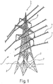
- the lattice mast 1 as a lattice mast structure according to the present invention is in FIG. 1 designed as a conventional, open steel framework construction with four supports 2, which are formed in the present case as open angle sections 3 with two equal legs 4 and an angle peak 10.
- the lattice mast 1 is described here, for example, as a truss structure with angle profiles, in particular as an open steel truss structure.
- lattice mast structures and bridge structures, pylons or similar structures can be provided as truss structure.
- the lattice mast takes in the field of its establishment a relatively large footprint on the four supports 2 of the lattice mast 1 converge towards a mast top 5.
- two supports 2 together with cross struts 6 trapezoidal fields a mast level.
- Each mast step is described in total by four trapezoidal fields, several mast steps extend in height from the base of the lattice mast 1 to the mast top 5.
- the individual fields of the steps of the lattice mast are formed as truss structures with diagonal struts 9, depending on the amount of transverse load of Lattice mast as pressure bars or tension bars act.
- the leaning towards the mast top 5 form of the lattice mast 1 is due to the expected bending stress of the lattice mast 1 due to wind load and due to lines 7.
- the lines 7 are suspended in a known manner to mast brackets 8.
- the geometry of the mast boom is adapted to the expected bending moment course due to the weight of the lines 7.
- FIG. 2 showing a sectional view of a support 2 of the lattice mast 1 as an angle section 3 in the sense of the present application.
- the section is shown as a cross section at the height of a node of the truss structure of the lattice mast 1.
- two transverse struts 6 are fastened to adjacent supports 2 on the legs 4 of the angle profile 3.
- the angle vertex 10 of the angle section 3 of the support 2 points outwards of the mast cross-section enclosed by the supports 2.
- 11 crampons are referred to the supports 2.
- the reinforcing rods 12 are attached to the legs 4 of the angle profile 3 outside the angle apex 10 adjacent, which are formed according to the invention as a two-part composite component.
- the reinforcing rods 12 comprise a steel braided sheath, which is laid as a continuous hose on the respective support 2 of the unspecified foundation of the lattice mast 1 to the mast top 5, and in each case in the region of the nodes of the truss structure, that is in the region of the support 2 connected crossbars 6 is connected to the support 2.
- the connection can be provided for example by means not shown clamps, with the supports 2 or welded to the angle profiles 3 of the supports 2.
- the reinforcing bars 12 further comprise a core of a hardened potting compound that has been pressed from below into the steel fabric tube.
- the finished and cured reinforcing rods 12 form a structural reinforcement of the angle sections 3 and thus an increase in their load and their free buckling length.
Claims (9)
- Structure de mât en treillis comprenant des montants (2), conçus sous la forme de profilés en acier, et des entretoises diagonales (9) s'étendant entre les montants (2) ou des entretoises transversales (6) s'étendant entre les montants (2) ou des entretoises diagonales (9) et des entretoises transversales (6) s'étendant entre les montants (3) et comprenant également au moins une barre de renforcement (12),
la barre de renforcement (12) s'étend dans la direction longitudinale d'un montant (2), la barre de renforcement (12) suivant l'allure générale du montant (2) ou d'une barre transversale (6) ou d'une entretoise diagonale, la barre de renforcement (12) étant reliée en au moins deux endroits espacés l'un de l'autre au montant (2) ou à une entretoise transversale (6) ou à une entretoise diagonale de sorte que, en termes de flux de force circulant à travers le montant (12) ou une entretoise transversale (6) ou une entretoise diagonale, la barre de renforcement (12) forme conjointement avec celui-ci ou celle-ci un composite structurel et la barre de renforcement (12) soit conçue sous la forme d'un composant composite, formé d'au moins deux parties, qui est conçu comme un composite structurel formé d'un élément transmettant principalement des forces de traction et d'un élément transmettant principalement des forces de compression, caractérisée en ce que la barre de renforcement (12) comporte une enveloppe formée d'une toile d'acier extensible résistant à la traction ou d'une toile textile renforcée de fibres d'acier, de fibres de carbone ou de fibre de verre ou d'une tresse d'acier et d'un noyau en matière d'enrobage durci, et la barre de renforcement (12) comprenant un noyau en acier qui est incorporé dans une enveloppe en matière d'enrobage durcie. - Structure de mât en treillis selon la revendication 1, caractérisée en ce que la barre de renforcement (12) comprend un élément de traction en acier ou en fibre de carbone ou en fibre de verre et un corps en matière d'enrobage durcissable.
- Structure de mât en treillis selon l'une des revendications 1 à 2, caractérisée en ce que la barre de renforcement (12) est reliée au montant (2) au niveau de points nodaux de la structure en treillis.
- Structure de mât en treillis selon l'une des revendications 1 à 3, caractérisée en ce que l'élément transmettant des forces de traction est précontraint.
- Structure de mât en treillis selon l'une des revendications 1 à 4, caractérisée en ce que la barre de renforcement (12) est reliée à une base du mât en treillis (1).
- Procédé d'augmentation de la stabilité d'une structure de mât en treillis, la structure de mât en treillis comprenant des montants (2) et des entretoises diagonales (9) ou des entretoises transversales (6) ou des entretoises diagonales (9) et des entretoises transversales (6), le procédé comprenant les étapes suivantes :- installer au moins un tuyau le long d'au moins un montant ou d'une entretoise transversale ou d'une entretoise diagonale sur au moins une partie de la longueur du montant ou d'une entretoise transversale ou d'une entretoise diagonale, le tuyau étant formé à partir d'une matière résistant à la traction ou le tuyau comportant une armature résistant à la traction ou le tuyau renfermant un élément résistant à la traction ou le tuyau étant fixé à un élément résistant à la traction,- fixer le tuyau et/ou l'élément résistant à la traction en plusieurs points de fixation espacés les uns des autres au niveau du montant (2) ou de l'entretoise transversale ou de l'entretoise diagonale et- injecter une matière d'enrobage durcissable dans le tuyau pour former une barre de renforcement,le tuyau renfermant au moins un câble en acier, le câble en acier étant fixé, au moins à ses deux extrémités, au montant (2) ou à une entretoise transversale (6) ou à une entretoise diagonale.
- Procédé selon la revendication 6, caractérisé en ce que l'on utilise comme tuyau un tuyau formé d'une toile en acier ou d'une tresse en acier.
- Procédé selon la revendication 6, caractérisé en ce que l'on utilise comme tuyau un tuyau textile de préférence comprenant une armature en acier, une armature en fibre de carbone ou une armature en fibre de verre ou une armature en fibre textile.
- Procédé selon l'une des revendications 6 à 8, caractérisé en ce que le tuyau et/ou l'élément résistant à la traction est relié, au niveau de points nodaux de la structure de mât en treillis, au montant (2) ou à une entretoise transversale (6) ou à une entretoise diagonale.
Applications Claiming Priority (2)
| Application Number | Priority Date | Filing Date | Title |
|---|---|---|---|
| DE102015210474.5A DE102015210474A1 (de) | 2015-06-09 | 2015-06-09 | Gittermaststruktur sowie Verfahren zur Standfestigkeitserhöhung an eine Gittermaststruktur |
| PCT/EP2016/062115 WO2016198270A1 (fr) | 2015-06-09 | 2016-05-30 | Structure de pylône en treillis ainsi que procédé servant à améliorer la stabilité sur une structure de pylône en treillis |
Publications (2)
| Publication Number | Publication Date |
|---|---|
| EP3307967A1 EP3307967A1 (fr) | 2018-04-18 |
| EP3307967B1 true EP3307967B1 (fr) | 2019-11-13 |
Family
ID=56092913
Family Applications (1)
| Application Number | Title | Priority Date | Filing Date |
|---|---|---|---|
| EP16726079.3A Active EP3307967B1 (fr) | 2015-06-09 | 2016-05-30 | Structure de pylône en treillis ainsi que procédé servant à améliorer la stabilité sur une structure de pylône en treillis |
Country Status (6)
| Country | Link |
|---|---|
| US (1) | US10519683B2 (fr) |
| EP (1) | EP3307967B1 (fr) |
| JP (1) | JP2018518617A (fr) |
| DE (1) | DE102015210474A1 (fr) |
| ES (1) | ES2767299T3 (fr) |
| WO (1) | WO2016198270A1 (fr) |
Families Citing this family (2)
| Publication number | Priority date | Publication date | Assignee | Title |
|---|---|---|---|---|
| DE102015210474A1 (de) * | 2015-06-09 | 2016-12-15 | Rwe Innogy Gmbh | Gittermaststruktur sowie Verfahren zur Standfestigkeitserhöhung an eine Gittermaststruktur |
| WO2021077893A1 (fr) * | 2019-10-22 | 2021-04-29 | 广州容联建筑科技有限公司 | Cadre de gabarit de tressage de cage d'armature de poteau/poutre et cadre de gabarit de tressage de cage d'armature de mur |
Family Cites Families (35)
| Publication number | Priority date | Publication date | Assignee | Title |
|---|---|---|---|---|
| GB550718A (fr) * | 1900-01-01 | |||
| GB518718A (en) | 1938-08-24 | 1940-03-06 | Henleys Telegraph Works Co Ltd | Improved rubber-like compositions |
| GB675859A (en) | 1949-05-18 | 1952-07-16 | Pirelli General Cable Works | Improvements in or relating to lattice towers |
| DE818108C (de) * | 1949-12-04 | 1951-10-22 | Eduard Burbach | Verstaerkungsstaebe fuer Walzprofile unter Knicklast |
| GB678859A (en) | 1950-05-23 | 1952-09-10 | Ici Ltd | Improvements in and relating to volumetric measuring and dispensing devices for granular and powdered materials |
| US2988182A (en) * | 1957-08-05 | 1961-06-13 | Univ Kingston | Extruded shapes |
| JPH09217419A (ja) * | 1996-02-13 | 1997-08-19 | Taisei Corp | 鉄骨部材の補強構造 |
| JP2001003600A (ja) * | 1999-06-25 | 2001-01-09 | Hazama Gumi Ltd | 鉄骨塔状建造物の脚部構造 |
| DE19939799A1 (de) * | 1999-08-21 | 2001-02-22 | Gebhardt & Koenig Gesteins Und | Verfahren und Anordnung zur Sanierung bzw. Verstärkung von Stützen |
| HUP0201136A2 (hu) * | 2002-04-03 | 2004-04-28 | Meir Silber | Toronyszerkezet |
| CA2539163A1 (fr) | 2003-09-15 | 2005-03-24 | The University Of Southern Queensland | Enveloppe de pieu |
| JP4309783B2 (ja) * | 2004-03-02 | 2009-08-05 | 九州電力株式会社 | 中空鋼管鉄塔を補強するための添接丸材による補強構造 |
| JP4386804B2 (ja) | 2004-07-16 | 2009-12-16 | 新日鉄エンジニアリング株式会社 | 既設鉄塔の耐震補強構造 |
| SG120189A1 (en) * | 2004-08-27 | 2006-03-28 | Offshore Technology Dev Pte Lt | Brace assembly for truss legs of offshore structures |
| US20090300996A1 (en) * | 2005-06-21 | 2009-12-10 | Tim Jones | System for reinforcing towers and the like |
| US20080092478A1 (en) * | 2006-10-24 | 2008-04-24 | Kyung Won Min | Friction type retrofitting device for steel tower structures |
| HUP0800070A2 (en) * | 2008-02-04 | 2009-09-28 | Meir Silber | Methods for reinforcing existing lattice frame structures having hollow steel primary elements, particularly steel towers with tubular legs |
| US8533658B2 (en) * | 2008-07-25 | 2013-09-10 | Northrop Grumman Systems Corporation | System and method for teaching software development processes |
| US8534025B2 (en) * | 2008-12-31 | 2013-09-17 | Seccional Brasil SA | Metallic tower |
| US8713891B2 (en) | 2009-02-27 | 2014-05-06 | Fyfe Co., Llc | Methods of reinforcing structures against blast events |
| US8650831B2 (en) | 2011-07-14 | 2014-02-18 | Mohammad R. Ehsani | Reconstruction methods for structural elements |
| US20110133475A1 (en) * | 2010-04-23 | 2011-06-09 | Danian Zheng | Support tower for use with a wind turbine and system for designing support tower |
| CA2800707A1 (fr) * | 2010-05-25 | 2011-12-01 | Siemens Aktiengesellschaft | Structure de chemise pour constructions en mer |
| US20130047544A1 (en) * | 2011-08-26 | 2013-02-28 | Nucor Corporation | Pre-fabricated interchangeable trusses |
| JP6258305B2 (ja) * | 2012-06-10 | 2018-01-10 | エムエイチアイ ヴェスタス オフショア ウィンド エー/エス | 格子型骨組用の節点構造体 |
| EP2858769A1 (fr) * | 2012-06-10 | 2015-04-15 | MHI Vestas Offshore Wind A/S | Structures de noeud pour cadres en treillis |
| CN103452370B (zh) * | 2012-10-25 | 2015-12-16 | 江苏神马电力股份有限公司 | 电网输电线用复合杆塔及其复合横担结构 |
| US9038348B1 (en) * | 2013-12-18 | 2015-05-26 | General Electric Company | Lattice tower assembly for a wind turbine |
| DE102014001893A1 (de) * | 2014-02-12 | 2015-08-13 | Rwe Deutschland Ag | Aerodynamische Verkleidung an Fachwerkstrukturen sowie Verfahren zur Standfestigkeitserhöhung von Fachwerkstrukturen |
| US20160060886A1 (en) * | 2014-09-03 | 2016-03-03 | Structural Components Llc | Methods and apparatuses for reinforcing structural members |
| DE102014219482A1 (de) * | 2014-09-25 | 2016-03-31 | Rwe Innogy Gmbh | Übergangsstück für Windenergieanlagen und Anschlussbauwerke |
| PL3221530T3 (pl) * | 2014-11-21 | 2019-09-30 | Danmarks Tekniske Universitet | System zbrojenia i sposób zbrojenia konstrukcji cięgnem |
| DE102015210474A1 (de) * | 2015-06-09 | 2016-12-15 | Rwe Innogy Gmbh | Gittermaststruktur sowie Verfahren zur Standfestigkeitserhöhung an eine Gittermaststruktur |
| US9719242B2 (en) * | 2015-09-18 | 2017-08-01 | Caterpillar Inc. | Node for a space frame |
| WO2017141195A1 (fr) * | 2016-02-18 | 2017-08-24 | The Hong Kong Polytechnic University | Éléments de renfort améliorés pour structures en béton |
-
2015
- 2015-06-09 DE DE102015210474.5A patent/DE102015210474A1/de not_active Withdrawn
-
2016
- 2016-05-30 WO PCT/EP2016/062115 patent/WO2016198270A1/fr active Application Filing
- 2016-05-30 ES ES16726079T patent/ES2767299T3/es active Active
- 2016-05-30 JP JP2017563552A patent/JP2018518617A/ja active Pending
- 2016-05-30 US US15/580,878 patent/US10519683B2/en not_active Expired - Fee Related
- 2016-05-30 EP EP16726079.3A patent/EP3307967B1/fr active Active
Non-Patent Citations (1)
| Title |
|---|
| None * |
Also Published As
| Publication number | Publication date |
|---|---|
| EP3307967A1 (fr) | 2018-04-18 |
| DE102015210474A1 (de) | 2016-12-15 |
| US10519683B2 (en) | 2019-12-31 |
| ES2767299T3 (es) | 2020-06-17 |
| US20180355631A1 (en) | 2018-12-13 |
| WO2016198270A1 (fr) | 2016-12-15 |
| JP2018518617A (ja) | 2018-07-12 |
Similar Documents
| Publication | Publication Date | Title |
|---|---|---|
| EP2914790B1 (fr) | Procédé de construction d'une tour en béton armé | |
| EP1924751B1 (fr) | Corps d'armature realise en plastique renforce par fibres | |
| WO2014166003A2 (fr) | Procédé de production de structures en béton précontraint au moyen de profilés en alliage à mémoire de forme, et structure fabriquée selon ledit procédé | |
| CH710538A2 (de) | Verfahren zum Erstellen von vorgespannten Bauwerken oder Bauteilen mittels Zugelementen aus Formgedächtnis-Legierungen sowie damit ausgerüstetes Bauwerk oder Bauteil. | |
| EP0960986A2 (fr) | Procédé et dispositif pour la construction de structures élancées et creuses du type tour de deux cent mètres et plus de haut, spécialement tour pour aérogénérateurs | |
| EP3662122A1 (fr) | Fondation pour un ouvrage | |
| DE102014103477A1 (de) | Ausbausystem für untertägige Tunnel oder Strecken, Ausbaueinheit sowie Bogensegment | |
| EP3307967B1 (fr) | Structure de pylône en treillis ainsi que procédé servant à améliorer la stabilité sur une structure de pylône en treillis | |
| EP0499590A1 (fr) | Elément connecteur isolant pour planchers de balcon et l'usage de cet élément | |
| EP3607147A1 (fr) | Construction en mer | |
| DE102014100814B4 (de) | Turmbauwerk für eine Windenergieanlage | |
| EP3437168A1 (fr) | Procédé d'extension de la capacité de transmission électrique d'un système de pylônes de lignes électriques aériennes | |
| EP3105394B1 (fr) | Pylône en treillis à structure charpentée ouverte, en particulier un pylône de ligne électrique ou un pylône de télécommunications, et procédé de d'augmentation de la résistance de pylônes en treillis à structure charpentée ouverte | |
| WO2002012657A1 (fr) | Module de construction destine a la fabrication de ponts, de batiments et de tours, par exemple dans des installations eoliennes | |
| DE102016106290A1 (de) | Bewehrungselement | |
| DE102013100176A1 (de) | Turm, insbesondere für Stromleitungen | |
| EP1873331A2 (fr) | Pylône de ligne électrique aérienne en béton centrifugé | |
| DE102016109234B4 (de) | Adapterstück mit verschiebbaren Kupplungselementen und Überdachungssystem | |
| LU502258B1 (de) | Verfahren zur Herstellung eines Röhrenkomplexes | |
| EP3739141B1 (fr) | Composant mural isolé | |
| DE102010040332B4 (de) | Gründungselement | |
| DE102009053356A1 (de) | Fundament für Freileitungsmast | |
| DE19712105A1 (de) | Verbundbaudecke für Hochbauten | |
| DE1582737C (de) | Hopfengerustanlage | |
| DE102015110863A1 (de) | Wandbauelement |
Legal Events
| Date | Code | Title | Description |
|---|---|---|---|
| STAA | Information on the status of an ep patent application or granted ep patent |
Free format text: STATUS: THE INTERNATIONAL PUBLICATION HAS BEEN MADE |
|
| PUAI | Public reference made under article 153(3) epc to a published international application that has entered the european phase |
Free format text: ORIGINAL CODE: 0009012 |
|
| STAA | Information on the status of an ep patent application or granted ep patent |
Free format text: STATUS: REQUEST FOR EXAMINATION WAS MADE |
|
| 17P | Request for examination filed |
Effective date: 20180109 |
|
| AK | Designated contracting states |
Kind code of ref document: A1 Designated state(s): AL AT BE BG CH CY CZ DE DK EE ES FI FR GB GR HR HU IE IS IT LI LT LU LV MC MK MT NL NO PL PT RO RS SE SI SK SM TR |
|
| AX | Request for extension of the european patent |
Extension state: BA ME |
|
| DAV | Request for validation of the european patent (deleted) | ||
| DAX | Request for extension of the european patent (deleted) | ||
| STAA | Information on the status of an ep patent application or granted ep patent |
Free format text: STATUS: EXAMINATION IS IN PROGRESS |
|
| 17Q | First examination report despatched |
Effective date: 20190122 |
|
| REG | Reference to a national code |
Ref country code: DE Ref legal event code: R079 Ref document number: 502016007572 Country of ref document: DE Free format text: PREVIOUS MAIN CLASS: E04H0012100000 Ipc: E04C0005070000 |
|
| GRAP | Despatch of communication of intention to grant a patent |
Free format text: ORIGINAL CODE: EPIDOSNIGR1 |
|
| STAA | Information on the status of an ep patent application or granted ep patent |
Free format text: STATUS: GRANT OF PATENT IS INTENDED |
|
| RIC1 | Information provided on ipc code assigned before grant |
Ipc: E04H 12/10 20060101ALI20190521BHEP Ipc: E04C 5/07 20060101AFI20190521BHEP Ipc: E04H 12/16 20060101ALI20190521BHEP |
|
| INTG | Intention to grant announced |
Effective date: 20190607 |
|
| RIN1 | Information on inventor provided before grant (corrected) |
Inventor name: BARTMINN, DANIEL |
|
| GRAS | Grant fee paid |
Free format text: ORIGINAL CODE: EPIDOSNIGR3 |
|
| GRAA | (expected) grant |
Free format text: ORIGINAL CODE: 0009210 |
|
| STAA | Information on the status of an ep patent application or granted ep patent |
Free format text: STATUS: THE PATENT HAS BEEN GRANTED |
|
| AK | Designated contracting states |
Kind code of ref document: B1 Designated state(s): AL AT BE BG CH CY CZ DE DK EE ES FI FR GB GR HR HU IE IS IT LI LT LU LV MC MK MT NL NO PL PT RO RS SE SI SK SM TR |
|
| REG | Reference to a national code |
Ref country code: CH Ref legal event code: EP Ref country code: AT Ref legal event code: REF Ref document number: 1201791 Country of ref document: AT Kind code of ref document: T Effective date: 20191115 |
|
| REG | Reference to a national code |
Ref country code: DE Ref legal event code: R096 Ref document number: 502016007572 Country of ref document: DE |
|
| REG | Reference to a national code |
Ref country code: IE Ref legal event code: FG4D Free format text: LANGUAGE OF EP DOCUMENT: GERMAN |
|
| REG | Reference to a national code |
Ref country code: NL Ref legal event code: MP Effective date: 20191113 |
|
| REG | Reference to a national code |
Ref country code: LT Ref legal event code: MG4D |
|
| PG25 | Lapsed in a contracting state [announced via postgrant information from national office to epo] |
Ref country code: LT Free format text: LAPSE BECAUSE OF FAILURE TO SUBMIT A TRANSLATION OF THE DESCRIPTION OR TO PAY THE FEE WITHIN THE PRESCRIBED TIME-LIMIT Effective date: 20191113 Ref country code: NL Free format text: LAPSE BECAUSE OF FAILURE TO SUBMIT A TRANSLATION OF THE DESCRIPTION OR TO PAY THE FEE WITHIN THE PRESCRIBED TIME-LIMIT Effective date: 20191113 Ref country code: BG Free format text: LAPSE BECAUSE OF FAILURE TO SUBMIT A TRANSLATION OF THE DESCRIPTION OR TO PAY THE FEE WITHIN THE PRESCRIBED TIME-LIMIT Effective date: 20200213 Ref country code: FI Free format text: LAPSE BECAUSE OF FAILURE TO SUBMIT A TRANSLATION OF THE DESCRIPTION OR TO PAY THE FEE WITHIN THE PRESCRIBED TIME-LIMIT Effective date: 20191113 Ref country code: GR Free format text: LAPSE BECAUSE OF FAILURE TO SUBMIT A TRANSLATION OF THE DESCRIPTION OR TO PAY THE FEE WITHIN THE PRESCRIBED TIME-LIMIT Effective date: 20200214 Ref country code: PL Free format text: LAPSE BECAUSE OF FAILURE TO SUBMIT A TRANSLATION OF THE DESCRIPTION OR TO PAY THE FEE WITHIN THE PRESCRIBED TIME-LIMIT Effective date: 20191113 Ref country code: NO Free format text: LAPSE BECAUSE OF FAILURE TO SUBMIT A TRANSLATION OF THE DESCRIPTION OR TO PAY THE FEE WITHIN THE PRESCRIBED TIME-LIMIT Effective date: 20200213 Ref country code: PT Free format text: LAPSE BECAUSE OF FAILURE TO SUBMIT A TRANSLATION OF THE DESCRIPTION OR TO PAY THE FEE WITHIN THE PRESCRIBED TIME-LIMIT Effective date: 20200313 Ref country code: SE Free format text: LAPSE BECAUSE OF FAILURE TO SUBMIT A TRANSLATION OF THE DESCRIPTION OR TO PAY THE FEE WITHIN THE PRESCRIBED TIME-LIMIT Effective date: 20191113 Ref country code: LV Free format text: LAPSE BECAUSE OF FAILURE TO SUBMIT A TRANSLATION OF THE DESCRIPTION OR TO PAY THE FEE WITHIN THE PRESCRIBED TIME-LIMIT Effective date: 20191113 |
|
| PG25 | Lapsed in a contracting state [announced via postgrant information from national office to epo] |
Ref country code: HR Free format text: LAPSE BECAUSE OF FAILURE TO SUBMIT A TRANSLATION OF THE DESCRIPTION OR TO PAY THE FEE WITHIN THE PRESCRIBED TIME-LIMIT Effective date: 20191113 Ref country code: RS Free format text: LAPSE BECAUSE OF FAILURE TO SUBMIT A TRANSLATION OF THE DESCRIPTION OR TO PAY THE FEE WITHIN THE PRESCRIBED TIME-LIMIT Effective date: 20191113 Ref country code: IS Free format text: LAPSE BECAUSE OF FAILURE TO SUBMIT A TRANSLATION OF THE DESCRIPTION OR TO PAY THE FEE WITHIN THE PRESCRIBED TIME-LIMIT Effective date: 20200313 |
|
| REG | Reference to a national code |
Ref country code: ES Ref legal event code: FG2A Ref document number: 2767299 Country of ref document: ES Kind code of ref document: T3 Effective date: 20200617 |
|
| PG25 | Lapsed in a contracting state [announced via postgrant information from national office to epo] |
Ref country code: AL Free format text: LAPSE BECAUSE OF FAILURE TO SUBMIT A TRANSLATION OF THE DESCRIPTION OR TO PAY THE FEE WITHIN THE PRESCRIBED TIME-LIMIT Effective date: 20191113 |
|
| PG25 | Lapsed in a contracting state [announced via postgrant information from national office to epo] |
Ref country code: RO Free format text: LAPSE BECAUSE OF FAILURE TO SUBMIT A TRANSLATION OF THE DESCRIPTION OR TO PAY THE FEE WITHIN THE PRESCRIBED TIME-LIMIT Effective date: 20191113 Ref country code: CZ Free format text: LAPSE BECAUSE OF FAILURE TO SUBMIT A TRANSLATION OF THE DESCRIPTION OR TO PAY THE FEE WITHIN THE PRESCRIBED TIME-LIMIT Effective date: 20191113 Ref country code: DK Free format text: LAPSE BECAUSE OF FAILURE TO SUBMIT A TRANSLATION OF THE DESCRIPTION OR TO PAY THE FEE WITHIN THE PRESCRIBED TIME-LIMIT Effective date: 20191113 Ref country code: EE Free format text: LAPSE BECAUSE OF FAILURE TO SUBMIT A TRANSLATION OF THE DESCRIPTION OR TO PAY THE FEE WITHIN THE PRESCRIBED TIME-LIMIT Effective date: 20191113 |
|
| REG | Reference to a national code |
Ref country code: DE Ref legal event code: R097 Ref document number: 502016007572 Country of ref document: DE |
|
| PG25 | Lapsed in a contracting state [announced via postgrant information from national office to epo] |
Ref country code: SK Free format text: LAPSE BECAUSE OF FAILURE TO SUBMIT A TRANSLATION OF THE DESCRIPTION OR TO PAY THE FEE WITHIN THE PRESCRIBED TIME-LIMIT Effective date: 20191113 Ref country code: SM Free format text: LAPSE BECAUSE OF FAILURE TO SUBMIT A TRANSLATION OF THE DESCRIPTION OR TO PAY THE FEE WITHIN THE PRESCRIBED TIME-LIMIT Effective date: 20191113 |
|
| PLBE | No opposition filed within time limit |
Free format text: ORIGINAL CODE: 0009261 |
|
| STAA | Information on the status of an ep patent application or granted ep patent |
Free format text: STATUS: NO OPPOSITION FILED WITHIN TIME LIMIT |
|
| REG | Reference to a national code |
Ref country code: DE Ref legal event code: R081 Ref document number: 502016007572 Country of ref document: DE Owner name: AMPRION GMBH, DE Free format text: FORMER OWNER: INNOGY SE, 45128 ESSEN, DE Ref country code: DE Ref legal event code: R081 Ref document number: 502016007572 Country of ref document: DE Owner name: RWE RENEWABLES GMBH, DE Free format text: FORMER OWNER: INNOGY SE, 45128 ESSEN, DE |
|
| 26N | No opposition filed |
Effective date: 20200814 |
|
| PG25 | Lapsed in a contracting state [announced via postgrant information from national office to epo] |
Ref country code: SI Free format text: LAPSE BECAUSE OF FAILURE TO SUBMIT A TRANSLATION OF THE DESCRIPTION OR TO PAY THE FEE WITHIN THE PRESCRIBED TIME-LIMIT Effective date: 20191113 |
|
| PG25 | Lapsed in a contracting state [announced via postgrant information from national office to epo] |
Ref country code: CH Free format text: LAPSE BECAUSE OF NON-PAYMENT OF DUE FEES Effective date: 20200531 Ref country code: MC Free format text: LAPSE BECAUSE OF FAILURE TO SUBMIT A TRANSLATION OF THE DESCRIPTION OR TO PAY THE FEE WITHIN THE PRESCRIBED TIME-LIMIT Effective date: 20191113 Ref country code: LI Free format text: LAPSE BECAUSE OF NON-PAYMENT OF DUE FEES Effective date: 20200531 |
|
| REG | Reference to a national code |
Ref country code: BE Ref legal event code: MM Effective date: 20200531 |
|
| PG25 | Lapsed in a contracting state [announced via postgrant information from national office to epo] |
Ref country code: LU Free format text: LAPSE BECAUSE OF NON-PAYMENT OF DUE FEES Effective date: 20200530 |
|
| PG25 | Lapsed in a contracting state [announced via postgrant information from national office to epo] |
Ref country code: IE Free format text: LAPSE BECAUSE OF NON-PAYMENT OF DUE FEES Effective date: 20200530 |
|
| PG25 | Lapsed in a contracting state [announced via postgrant information from national office to epo] |
Ref country code: BE Free format text: LAPSE BECAUSE OF NON-PAYMENT OF DUE FEES Effective date: 20200531 |
|
| PGFP | Annual fee paid to national office [announced via postgrant information from national office to epo] |
Ref country code: ES Payment date: 20210618 Year of fee payment: 6 |
|
| PG25 | Lapsed in a contracting state [announced via postgrant information from national office to epo] |
Ref country code: TR Free format text: LAPSE BECAUSE OF FAILURE TO SUBMIT A TRANSLATION OF THE DESCRIPTION OR TO PAY THE FEE WITHIN THE PRESCRIBED TIME-LIMIT Effective date: 20191113 Ref country code: MT Free format text: LAPSE BECAUSE OF FAILURE TO SUBMIT A TRANSLATION OF THE DESCRIPTION OR TO PAY THE FEE WITHIN THE PRESCRIBED TIME-LIMIT Effective date: 20191113 Ref country code: CY Free format text: LAPSE BECAUSE OF FAILURE TO SUBMIT A TRANSLATION OF THE DESCRIPTION OR TO PAY THE FEE WITHIN THE PRESCRIBED TIME-LIMIT Effective date: 20191113 |
|
| PG25 | Lapsed in a contracting state [announced via postgrant information from national office to epo] |
Ref country code: MK Free format text: LAPSE BECAUSE OF FAILURE TO SUBMIT A TRANSLATION OF THE DESCRIPTION OR TO PAY THE FEE WITHIN THE PRESCRIBED TIME-LIMIT Effective date: 20191113 |
|
| REG | Reference to a national code |
Ref country code: AT Ref legal event code: MM01 Ref document number: 1201791 Country of ref document: AT Kind code of ref document: T Effective date: 20210530 |
|
| PG25 | Lapsed in a contracting state [announced via postgrant information from national office to epo] |
Ref country code: AT Free format text: LAPSE BECAUSE OF NON-PAYMENT OF DUE FEES Effective date: 20210530 |
|
| REG | Reference to a national code |
Ref country code: DE Ref legal event code: R081 Ref document number: 502016007572 Country of ref document: DE Owner name: AMPRION GMBH, DE Free format text: FORMER OWNER: RWE RENEWABLES GMBH, 45145 ESSEN, DE |
|
| REG | Reference to a national code |
Ref country code: GB Ref legal event code: 732E Free format text: REGISTERED BETWEEN 20230420 AND 20230426 |
|
| REG | Reference to a national code |
Ref country code: ES Ref legal event code: FD2A Effective date: 20230630 |
|
| PG25 | Lapsed in a contracting state [announced via postgrant information from national office to epo] |
Ref country code: ES Free format text: LAPSE BECAUSE OF NON-PAYMENT OF DUE FEES Effective date: 20220531 |
|
| PGFP | Annual fee paid to national office [announced via postgrant information from national office to epo] |
Ref country code: FR Payment date: 20230627 Year of fee payment: 8 Ref country code: DE Payment date: 20230627 Year of fee payment: 8 |
|
| PGFP | Annual fee paid to national office [announced via postgrant information from national office to epo] |
Ref country code: IT Payment date: 20230630 Year of fee payment: 8 Ref country code: GB Payment date: 20230627 Year of fee payment: 8 |