EP3306441B1 - Temperature control method and apparatus - Google Patents
Temperature control method and apparatus Download PDFInfo
- Publication number
- EP3306441B1 EP3306441B1 EP16205098.3A EP16205098A EP3306441B1 EP 3306441 B1 EP3306441 B1 EP 3306441B1 EP 16205098 A EP16205098 A EP 16205098A EP 3306441 B1 EP3306441 B1 EP 3306441B1
- Authority
- EP
- European Patent Office
- Prior art keywords
- terminal
- user interface
- screen
- state
- module
- Prior art date
- Legal status (The legal status is an assumption and is not a legal conclusion. Google has not performed a legal analysis and makes no representation as to the accuracy of the status listed.)
- Active
Links
- 238000000034 method Methods 0.000 title claims description 39
- 238000010586 diagram Methods 0.000 description 17
- 238000004891 communication Methods 0.000 description 11
- 230000006870 function Effects 0.000 description 9
- 238000011217 control strategy Methods 0.000 description 6
- 238000005516 engineering process Methods 0.000 description 6
- 230000003287 optical effect Effects 0.000 description 4
- 230000005236 sound signal Effects 0.000 description 4
- 238000007726 management method Methods 0.000 description 3
- 230000009471 action Effects 0.000 description 2
- 230000008859 change Effects 0.000 description 2
- 230000003993 interaction Effects 0.000 description 2
- 230000001133 acceleration Effects 0.000 description 1
- 238000003491 array Methods 0.000 description 1
- 238000004590 computer program Methods 0.000 description 1
- 238000013500 data storage Methods 0.000 description 1
- 230000001419 dependent effect Effects 0.000 description 1
- 230000007613 environmental effect Effects 0.000 description 1
- 230000017525 heat dissipation Effects 0.000 description 1
- 238000003384 imaging method Methods 0.000 description 1
- 239000004973 liquid crystal related substance Substances 0.000 description 1
- 206010025482 malaise Diseases 0.000 description 1
- 230000002093 peripheral effect Effects 0.000 description 1
- 230000008569 process Effects 0.000 description 1
- 239000007787 solid Substances 0.000 description 1
- 230000003068 static effect Effects 0.000 description 1
- 230000001960 triggered effect Effects 0.000 description 1
Images


Classifications
-
- H—ELECTRICITY
- H04—ELECTRIC COMMUNICATION TECHNIQUE
- H04W—WIRELESS COMMUNICATION NETWORKS
- H04W52/00—Power management, e.g. TPC [Transmission Power Control], power saving or power classes
- H04W52/02—Power saving arrangements
- H04W52/0209—Power saving arrangements in terminal devices
- H04W52/0251—Power saving arrangements in terminal devices using monitoring of local events, e.g. events related to user activity
- H04W52/0254—Power saving arrangements in terminal devices using monitoring of local events, e.g. events related to user activity detecting a user operation or a tactile contact or a motion of the device
-
- G—PHYSICS
- G06—COMPUTING; CALCULATING OR COUNTING
- G06F—ELECTRIC DIGITAL DATA PROCESSING
- G06F1/00—Details not covered by groups G06F3/00 - G06F13/00 and G06F21/00
- G06F1/16—Constructional details or arrangements
- G06F1/20—Cooling means
- G06F1/206—Cooling means comprising thermal management
-
- G—PHYSICS
- G06—COMPUTING; CALCULATING OR COUNTING
- G06F—ELECTRIC DIGITAL DATA PROCESSING
- G06F1/00—Details not covered by groups G06F3/00 - G06F13/00 and G06F21/00
- G06F1/26—Power supply means, e.g. regulation thereof
- G06F1/32—Means for saving power
- G06F1/3203—Power management, i.e. event-based initiation of a power-saving mode
- G06F1/3206—Monitoring of events, devices or parameters that trigger a change in power modality
- G06F1/3215—Monitoring of peripheral devices
-
- G—PHYSICS
- G06—COMPUTING; CALCULATING OR COUNTING
- G06F—ELECTRIC DIGITAL DATA PROCESSING
- G06F1/00—Details not covered by groups G06F3/00 - G06F13/00 and G06F21/00
- G06F1/26—Power supply means, e.g. regulation thereof
- G06F1/32—Means for saving power
- G06F1/3203—Power management, i.e. event-based initiation of a power-saving mode
- G06F1/3206—Monitoring of events, devices or parameters that trigger a change in power modality
- G06F1/3231—Monitoring the presence, absence or movement of users
-
- G—PHYSICS
- G06—COMPUTING; CALCULATING OR COUNTING
- G06F—ELECTRIC DIGITAL DATA PROCESSING
- G06F1/00—Details not covered by groups G06F3/00 - G06F13/00 and G06F21/00
- G06F1/26—Power supply means, e.g. regulation thereof
- G06F1/32—Means for saving power
- G06F1/3203—Power management, i.e. event-based initiation of a power-saving mode
- G06F1/3234—Power saving characterised by the action undertaken
- G06F1/325—Power saving in peripheral device
- G06F1/3265—Power saving in display device
-
- G—PHYSICS
- G06—COMPUTING; CALCULATING OR COUNTING
- G06F—ELECTRIC DIGITAL DATA PROCESSING
- G06F1/00—Details not covered by groups G06F3/00 - G06F13/00 and G06F21/00
- G06F1/26—Power supply means, e.g. regulation thereof
- G06F1/32—Means for saving power
- G06F1/3203—Power management, i.e. event-based initiation of a power-saving mode
- G06F1/3234—Power saving characterised by the action undertaken
- G06F1/329—Power saving characterised by the action undertaken by task scheduling
-
- G—PHYSICS
- G06—COMPUTING; CALCULATING OR COUNTING
- G06F—ELECTRIC DIGITAL DATA PROCESSING
- G06F3/00—Input arrangements for transferring data to be processed into a form capable of being handled by the computer; Output arrangements for transferring data from processing unit to output unit, e.g. interface arrangements
- G06F3/01—Input arrangements or combined input and output arrangements for interaction between user and computer
- G06F3/048—Interaction techniques based on graphical user interfaces [GUI]
- G06F3/0487—Interaction techniques based on graphical user interfaces [GUI] using specific features provided by the input device, e.g. functions controlled by the rotation of a mouse with dual sensing arrangements, or of the nature of the input device, e.g. tap gestures based on pressure sensed by a digitiser
- G06F3/0488—Interaction techniques based on graphical user interfaces [GUI] using specific features provided by the input device, e.g. functions controlled by the rotation of a mouse with dual sensing arrangements, or of the nature of the input device, e.g. tap gestures based on pressure sensed by a digitiser using a touch-screen or digitiser, e.g. input of commands through traced gestures
-
- H—ELECTRICITY
- H04—ELECTRIC COMMUNICATION TECHNIQUE
- H04M—TELEPHONIC COMMUNICATION
- H04M1/00—Substation equipment, e.g. for use by subscribers
- H04M1/02—Constructional features of telephone sets
- H04M1/0202—Portable telephone sets, e.g. cordless phones, mobile phones or bar type handsets
- H04M1/026—Details of the structure or mounting of specific components
- H04M1/0266—Details of the structure or mounting of specific components for a display module assembly
-
- H—ELECTRICITY
- H04—ELECTRIC COMMUNICATION TECHNIQUE
- H04M—TELEPHONIC COMMUNICATION
- H04M1/00—Substation equipment, e.g. for use by subscribers
- H04M1/72—Mobile telephones; Cordless telephones, i.e. devices for establishing wireless links to base stations without route selection
- H04M1/724—User interfaces specially adapted for cordless or mobile telephones
- H04M1/72448—User interfaces specially adapted for cordless or mobile telephones with means for adapting the functionality of the device according to specific conditions
- H04M1/72454—User interfaces specially adapted for cordless or mobile telephones with means for adapting the functionality of the device according to specific conditions according to context-related or environment-related conditions
-
- H—ELECTRICITY
- H04—ELECTRIC COMMUNICATION TECHNIQUE
- H04W—WIRELESS COMMUNICATION NETWORKS
- H04W52/00—Power management, e.g. TPC [Transmission Power Control], power saving or power classes
- H04W52/02—Power saving arrangements
- H04W52/0209—Power saving arrangements in terminal devices
- H04W52/0261—Power saving arrangements in terminal devices managing power supply demand, e.g. depending on battery level
- H04W52/0264—Power saving arrangements in terminal devices managing power supply demand, e.g. depending on battery level by selectively disabling software applications
-
- H—ELECTRICITY
- H04—ELECTRIC COMMUNICATION TECHNIQUE
- H04W—WIRELESS COMMUNICATION NETWORKS
- H04W52/00—Power management, e.g. TPC [Transmission Power Control], power saving or power classes
- H04W52/02—Power saving arrangements
- H04W52/0209—Power saving arrangements in terminal devices
- H04W52/0261—Power saving arrangements in terminal devices managing power supply demand, e.g. depending on battery level
- H04W52/0267—Power saving arrangements in terminal devices managing power supply demand, e.g. depending on battery level by controlling user interface components
- H04W52/027—Power saving arrangements in terminal devices managing power supply demand, e.g. depending on battery level by controlling user interface components by controlling a display operation or backlight unit
-
- H—ELECTRICITY
- H04—ELECTRIC COMMUNICATION TECHNIQUE
- H04M—TELEPHONIC COMMUNICATION
- H04M2250/00—Details of telephonic subscriber devices
- H04M2250/22—Details of telephonic subscriber devices including a touch pad, a touch sensor or a touch detector
-
- Y—GENERAL TAGGING OF NEW TECHNOLOGICAL DEVELOPMENTS; GENERAL TAGGING OF CROSS-SECTIONAL TECHNOLOGIES SPANNING OVER SEVERAL SECTIONS OF THE IPC; TECHNICAL SUBJECTS COVERED BY FORMER USPC CROSS-REFERENCE ART COLLECTIONS [XRACs] AND DIGESTS
- Y02—TECHNOLOGIES OR APPLICATIONS FOR MITIGATION OR ADAPTATION AGAINST CLIMATE CHANGE
- Y02D—CLIMATE CHANGE MITIGATION TECHNOLOGIES IN INFORMATION AND COMMUNICATION TECHNOLOGIES [ICT], I.E. INFORMATION AND COMMUNICATION TECHNOLOGIES AIMING AT THE REDUCTION OF THEIR OWN ENERGY USE
- Y02D10/00—Energy efficient computing, e.g. low power processors, power management or thermal management
-
- Y—GENERAL TAGGING OF NEW TECHNOLOGICAL DEVELOPMENTS; GENERAL TAGGING OF CROSS-SECTIONAL TECHNOLOGIES SPANNING OVER SEVERAL SECTIONS OF THE IPC; TECHNICAL SUBJECTS COVERED BY FORMER USPC CROSS-REFERENCE ART COLLECTIONS [XRACs] AND DIGESTS
- Y02—TECHNOLOGIES OR APPLICATIONS FOR MITIGATION OR ADAPTATION AGAINST CLIMATE CHANGE
- Y02D—CLIMATE CHANGE MITIGATION TECHNOLOGIES IN INFORMATION AND COMMUNICATION TECHNOLOGIES [ICT], I.E. INFORMATION AND COMMUNICATION TECHNOLOGIES AIMING AT THE REDUCTION OF THEIR OWN ENERGY USE
- Y02D30/00—Reducing energy consumption in communication networks
- Y02D30/70—Reducing energy consumption in communication networks in wireless communication networks
Definitions
- the present disclosure generally relates to communication technology, and more particularly, to a temperature control method and a temperature control apparatus.
- Temperature of a terminal may rise continuously when the terminal is used. A user may feel unwell if the temperature increases to a certain degree. Therefore, it needs heat dissipation in time and to control the temperature of the terminal.
- resources of several components in the terminal may be limited to reduce a power consumption of the terminal if the temperature increases to the certain degree, thereby ensuring that the temperature of the terminal is in a regular range.
- US2014149753 provides a method, an apparatus, and a computer program product for allocating a total power budget among a plurality of components of a user device.
- the apparatus prioritizes the plurality of components based on a user experience model (performance/power model) for each of the plurality of components.
- the user experience model (performance/power model) of a component includes a measure of component attribute as a function of component power consumption.
- the apparatus allocates portions of the total power budget among the user-device components based on priority established by the user experience model.
- the apparatus may further prioritize the components based on weights assigned to the components.
- US2013099569 provides a charging control method adapted to be used in a portable electronic device.
- the portable electronic device includes a display module and a rechargeable battery.
- the charging control method includes the following steps. Firstly, a working status of the display module is obtained and a control signal is transmitted by a control unit. Next, the control signal is received and a charging power provided to the rechargeable battery is adjusted according to the control signal by a power control unit.
- US2012120625 provides a low profile display enclosure system for enclosing a display device for viewing that protects the display device from environmental effects and is configured to dissipate heat generated within the display enclosure.
- the substantially sealed display enclosure comprises a rigid bezel, a substantially transparent front cover coupled to the bezel, and a rear cover assembly that includes a heat sink portion.
- the thickness of the bezel is minimized to provide the enclosure with a low profile about the periphery of the display device enclosed therein.
- Thermal control devices may be mounted within the enclosure to modulate a temperature within the enclosure.
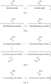
- Fig. 1 is a flow chart showing a temperature control method according to an exemplary embodiment. As shown in Fig. 1 , the temperature control method is applied in a terminal and includes followings.
- a current state of a user interface (UI for short) of a terminal is determined if a current temperature value of the terminal reaches a predetermined threshold, in which the current state of the UI includes an interacting state and a non-interacting state.
- the terminal determines the current temperature value by continuously detecting temperature values of each heat source in the terminal.
- the temperature value of the terminal may be detected by placing a corresponding temperature sensor within the terminal.
- the heat source in the terminal may include a processor, a charging module, a backlight module and the like.
- the current temperature value of the terminal reaches the predetermined threshold, it is determined whether the user is operating the terminal. It is illustrated that the current state of the UI of the terminal is the interacting state if the user is operating the terminal; otherwise, the current state of the UI of the terminal is the non-interacting state.
- a corresponding temperature control is performed on the terminal according to the current state of the UI.
- the temperature control is performed on the terminal.
- the temperature control strategy varies with the current temperature value and current state of the UI.
- the terminal may provide a selecting function for determining whether to activate the above temperature control method for the user.
- the terminal may perform the temperature control method automatically, if the user selects to activate the temperature control method; or, the terminal may automatically perform the temperature control method in a particular period or by being triggered via a particular event, according to a selection of the user.
- the temperature control is performed according to the current temperature value and the current state of the UI of the terminal.
- the temperature control strategy varies with the current temperature value and current state of the UI.
- the temperature control may be performed on the terminal in combination with an actual usage situation of the terminal such that the usage may not be influenced to a greatest extent when the temperature control is performed, thereby largely improving the user experience.
- Fig. 2 is a flow chart showing a temperature control method according to another exemplary embodiment. As shown in Fig. 2 , the block S12 may specifically include followings.
- a block S21 it is detected whether a screen of the terminal is on.
- Whether the screen of the terminal is on may be determined by detecting that the screen of the terminal is locked or unlocked. The screen of the terminal is on if the screen of the terminal is locked. And the screen of the terminal is off if the screen of the terminal is unlocked.
- whether the screen of the terminal is on may be determined also by detecting that the screen of the terminal is bright or dark. It is determined that the screen of the terminal is on if the screen of the terminal is bright. And it is determined that the screen of the terminal is off if the screen of the terminal is dark.
- a time factor may be employed. For example, it is determined that the screen of the terminal is off if the screen of the terminal is dark very soon after being bright. Only when a period that the screen of the terminal is unlocked or is bright is greater than a predetermined period, it is determined that the screen of the terminal is on, otherwise, it is determined that the screen of the terminal is off.
- the current state of the UI is determined as the interacting state if the screen of the terminal is on; otherwise, the current state of the UI is determined as the non-interacting state.
- the user is operating the terminal if the screen is on, and then the current state of the UI may be determined as the interacting state.
- the user is not operating the terminal directly if the screen is off, and then the current state of the UI may be determined as the non-interacting state.
- the terminal In a process that the terminal is used by the user, it is common that the user is operating the terminal if the screen of the terminal is unlocked or is bright. Therefore, in the embodiment, whether the screen of the terminal is on is taken as a condition for determining the current state of the UI of the terminal, which may ensure a correctness of determining the current state of the UI.
- Fig. 3 is a flow chart showing a temperature control method according to another exemplary embodiment. As shown in Fig. 3 , the block S12 may specifically includes followings.
- a block S31 it is determined whether there is a touch screen event in the terminal.
- Detecting whether there is a touch screen event is to detect whether the user is touching the screen.
- the current state of the UI is determined as the interacting state if there is the touch screen event in the terminal; otherwise, the current state of the UI is determined as the non-interacting state.
- the current state of the UI may be determined as the interacting state; otherwise, the current state of the UI may be determined as the non-interacting state.
- the current state of the UI of the terminal is determined via the touch screen event, which may reflect the current state of the UI of the terminal more directly and more precisely.
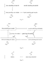
- Fig. 4 is a flow chart showing a temperature control method according to another exemplary embodiment. As shown in Fig. 4 , if the current temperature value of the terminal reaches a first predetermined threshold, the block S12 may specifically include followings.
- a block S41 it is judged whether the current state of the UI is the interacting state.
- a processor power consumption is not limited directly. It is continuously judged whether the current state of the UI is the interacting state, that is, it is determined whether the user is operating the terminal.
- a screen power consumption is reduced and a charging power consumption is reduced to a predetermined charging power consumption if the current state of the UI is the interacting state.
- the processor power consumption is not limited if the user is operating the terminal, the screen power consumption and the charging power consumption are reduced such that not only the temperature control but also a normal usage of the terminal by the user are ensured.
- a premise of reducing the charging power consumption is that the terminal is being charged, that is, if the current state of the UI is the interacting state and the terminal is being charged at the same time, then the charging power consumption is reduced.
- At least one of applications running in the terminal is closed according to a priority list of applications if the current state of the UI is the non-interacting state.
- the temperature control may be realized by limiting the processor power consumption if the user is not operating the terminal directly. Specifically, several applications running in the terminal may be closed in the priority list such that the processor power consumption may be reduced.
- the current temperature value of the terminal reaches a certain degree
- different temperature control strategies are performed according to the current states of the UI of the terminal. If the current state of the UI is the interacting state, in order to ensure that a system runs smoothly when the user is operating the terminal, instead of limiting the processor power consumption, the screen power consumption and the charging power consumption are limited to realize the temperature control. If the current state of the UI is the non-interacting state, the processor power consumption may be limited directly to realize the temperature control. Thus, the method realizes the corresponding temperature control according to the actual usage situation such that the usage may not be influenced to a greatest extent when the temperature control is performed, thereby largely improving the user experience.
- Fig. 5 is a flow chart showing a temperature control method according to another exemplary embodiment. As shown in Fig. 5 , when the current temperature value of the terminal reaches a second predetermined threshold, the block S12 may specifically include followings.
- a block S51 it is judged that whether the current state of the UI is the interacting state.
- the second predetermined threshold is greater than the first predetermined threshold.
- the temperature value of the terminal reaches a higher level. It may be unable to control the temperature of the terminal into a regular range if the above temperature control strategy is performed. Therefore, a stricter temperature control strategy may be performed.
- a block S52 the screen power consumption of the terminal is reduced and a charging function of the terminal is closed, if the current state of the UI is the interacting state.
- the charging function needs to be closed such that the charging power consumption is reduced to 0 to ensure the temperature control.
- a premise of closing the charging function is that the terminal is being charged, that is, if the current state of the UI is the interacting state and the terminal is being charged, the charging function of the terminal is closed.
- a block S53 at least one of the applications running in the terminal is closed according to the priority list of applications and a network power consumption of the terminal is reduced to a predetermined network power consumption, if the current state of the UI is the non-interacting state.
- the network power consumption needs to be limited. That is, the network function is limited (for example, music or video download via the network is limited) to ensure the temperature control.
- the current temperature value of the terminal reaches a certain degree
- different temperature control strategies are performed according to the current states of the UI of the terminal. If the current state of the UI is the interacting state, in order to ensure that a system runs smoothly when the user is operating the terminal, instead of limiting the processor power consumption, the screen power consumption is limited and the charging power consumption is closed to realize the temperature control. If the current state of the UI is the non-interacting state, the processor power consumption and the network power consumption may be limited directly to realize the temperature control. Thus, the method realizes the corresponding temperature control according to the actual usage situation such that the usage may not be influenced to a greatest extent when the temperature control is performed, thereby largely improving the user experience.
- the priority list of applications has existed when at least one of the applications running in the terminal is closed according to the priority list. That is to say, the priority list needs to be predetermined.
- the terminal may generate the priority list by defaulted. Or, the priority list may be set by inputting via the user. A latter one may be implemented by a following manner.
- Fig. 6 is a flow chart showing a temperature control method according to another exemplary embodiment. As shown in Fig. 6 , a method for determining the priority list includes followings.
- the terminal may provide a setting function for setting the priority of the applications.
- the terminal may provide icons or a name list of all applications in the terminal such that the user may input the priority information according to the icons and the name list.
- the priority list of applications is generated according to the application priority information.
- the priority list of applications is configured to indicate a priority order of applications, and at least one of the applications running in the terminal is closed in the priority order from low to high.
- the application priority information is set by the user such that a result that the terminal closes the applications according to the application priority information may reflect the user's demand accurately. Furthermore, there is not a case that the application considered to be important by the user is closed, thereby improving the user experience.
- a specific implementation of reducing the screen power consumption of the terminal may include:
- specific decrease degrees of the screen power consumption are different when the current temperature value reaches the first predetermined threshold or the second predetermined threshold. For example, if the current temperature value reaches the first predetermined threshold, the decrease degree of the screen power consumption is respective small. And if the current temperature value reaches the second predetermined threshold, the decrease degree of the screen power consumption is respective great.
- the screen power consumption is reduced by reducing the screen brightness of the screen and/or closing the screen key light such that the decrease of the power consumption is realized without influencing the user experience, thereby realizing the temperature control of the terminal.
- Fig. 7 is a block diagram illustrating a temperature control apparatus according to an exemplary embodiment. As shown in Fig. 7 , the apparatus includes a determining module 701 and the controlling module 702.
- the determining module 701 is configured to determine a current state of a user interface (UI for short) of a terminal if a current temperature value of the terminal reaches a predetermined threshold, in which the current state of the UI includes an interacting state and a non-interacting state.
- UI user interface
- the controlling module 702 is configured to perform a corresponding temperature control on the terminal according to the current state of the UI.
- Fig. 8 is a block diagram illustrating a temperature control apparatus according to another exemplary embodiment.
- the determining module 701 includes a first detecting sub-module 7011 and a first determining sub-module 7012.
- the first detecting sub-module 7011 is configured to detect whether a screen of the terminal is on.
- the first determining sub-module 7012 is configured to determine the current state of the UI as the interacting state if the screen of the terminal is on, otherwise, to determine the current state of the UI as the non-interacting state.
- Fig. 9 is a block diagram illustrating a temperature control apparatus according to another exemplary embodiment.
- the determining module 701 further includes a second detecting sub-module 7013 and a second determining sub-module 7014.
- the second detecting sub-module 7013 is configured to detect whether there is a touch screen event in the terminal.
- the second determining sub-module 7014 is configured to determine the current state of the UI as the interacting state if there is the touch screen event in the terminal, otherwise, to determine the current state of the UI as the non-interacting state.
- Fig. 10 is a block diagram illustrating a temperature control apparatus according to another exemplary embodiment.
- the controlling module 702 includes a first controlling sub-module 7021 and a second controlling sub-module 7022.
- the first controlling sub-module 7021 is configured to reduce a screen power consumption of the terminal and to reduce a charging power consumption of the terminal to a predetermined charging power consumption if the current state of the UI is the interacting state, when the current temperature value reaches a first predetermined threshold.
- the second controlling sub-module 7022 is configured to close at least one of applications running in the terminal according to a priority list of applications if the current state of the UI is the non-interacting state when the current temperature value reaches a first predetermined threshold.
- Fig. 11 is a block diagram illustrating a temperature control apparatus according to another exemplary embodiment.
- the controlling module 702 further includes a third controlling sub-module 7023 and a fourth controlling sub-module 7024.
- the third controlling sub-module 7023 is configured to reduce the screen power consumption of the terminal and to close a charging function of the terminal if the current state of the UI is the interacting state, when the current temperature value reaches a second predetermined threshold.
- the fourth controlling sub-module 7024 is configured to close at least one of the applications running in the terminal according to the priority list of applications and to reduce a network power consumption of the terminal to a predetermined network power consumption if the current state of the UI is the non-interacting state, when the current temperature value reaches a second predetermined threshold.
- Fig. 12 is a block diagram illustrating a temperature control apparatus according to another exemplary embodiment.
- the controlling module 702 includes a receiving sub-module 7025 and a generating sub-module 7026.
- the receiving sub-module 7025 is configured to receive application priority information input by a user before the second controlling sub-module or the fourth controlling sub-module closes at least one of the applications running in the terminal according to the priority list of applications.
- the generating sub-module 7026 is configured to generate the priority list of applications according to the application priority information.
- the priority list of applications is configured to indicate a priority order of applications, and at least one of the applications running in the terminal is closed in the priority order from low to high.
- the first controlling sub-module 7021 is specifically configured to:
- the third controlling sub-module 7023 is specifically configured to:
- Fig. 13 is a block diagram illustrating a terminal entity according to an exemplary embodiment. As shown in Fig. 13 , the terminal includes a memory 71 and a processing component 72.
- the memory 71 is configured to store an instruction executable by the processing component 72.
- the processing component 72 is configured to:
- the processing component 72 may be a central processing unit (CPU), or may be another general processor, a digital signal processor (DSP), an application specific integrated circuit (ASIC), etc.
- the general processor may be a microprocessor, or may be other regular processors, etc.
- the above memory may be a read-only memory (ROM), a random access memory (RAM), a flash memory, a disk or a solid state disk.
- ROM read-only memory
- RAM random access memory
- a SIM card is known as a user identification card, an intelligent card, and a digital mobile phone provided with the SIM card can be used. That is, the computer chip stores information of a user of the digital mobile phone and content such as an encrypted cipher code and a telephone dictionary etc.
- the acts in the method disclosed by combining embodiments of the present disclosure may be implemented by a hardware processor or a combination of hardware and software modules in the processor.
- Fig. 14 is a block diagram illustrating a device 800 for controlling temperature according to an exemplary embodiment.
- the device 800 may be a mobile phone, a computer, a digital broadcasting terminal, a messaging device, a game console, a tablet device, a medical device, fitness equipment, a Personal Digital Assistant PDA, and the like.
- the device 800 may include the following one or more components: a processing component 802, a memory 804, a power component 806, a multimedia component 808, an audio component 810, an Input/Output (I/O) interface 812, a sensor component 814, and a communication component 816.
- a processing component 802 a memory 804, a power component 806, a multimedia component 808, an audio component 810, an Input/Output (I/O) interface 812, a sensor component 814, and a communication component 816.
- the processing component 802 typically controls overall operations of the device 800, such as the operations associated with display, telephone calls, data communications, camera operations, and recording operations.
- the processing component 802 may include one or more processors 820 to execute instructions to perform all or part of the acts in the above described methods.
- the processing component 802 may include one or more modules which facilitate the interaction between the processing component 802 and other components.
- the processing component 802 may include a multimedia module to facilitate the interaction between the multimedia component 808 and the processing component 802.
- the memory 804 is configured to store various types of data to support the operation of the device 800. Examples of such data include instructions for any applications or methods operated on the device 800, contact data, phonebook data, messages, pictures, video, etc.
- the memory 804 may be implemented using any type of volatile or non-volatile memory devices, or a combination thereof, such as a static random access memory (SRAM), an electrically erasable programmable read-only memory (EEPROM), an erasable programmable read-only memory (EPROM), a programmable read-only memory (PROM), a read-only memory (ROM), a magnetic memory, a flash memory, a magnetic or optical disk.
- SRAM static random access memory
- EEPROM electrically erasable programmable read-only memory
- EPROM erasable programmable read-only memory
- PROM programmable read-only memory
- ROM read-only memory
- magnetic memory a magnetic memory
- flash memory a flash memory
- magnetic or optical disk a magnetic or optical
- the power component 806 provides power to various components of the device 800.
- the power component 806 may include a power management system, one or more power sources, and any other components associated with the generation, management, and distribution of power in the device 800.
- the multimedia component 808 includes a screen providing an output interface between the device 800 and the user.
- the screen may include a liquid crystal display (LCD) and a press panel (TP). If the screen includes the press panel, the screen may be implemented as a press screen to receive input signals from the user.
- the press panel includes one or more press sensors to sense presses, swipes, and other gestures on the press panel. The press sensors may not only sense a boundary of a press or swipe action, but also sense a duration time and a pressure associated with the press or swipe action.
- the multimedia component 808 includes a front camera and/or a rear camera. The front camera and/or the rear camera may receive external multimedia data while the device 800 is in an operation mode, such as a photographing mode or a video mode. Each of the front camera and the rear camera may be a fixed optical lens system or have focus and optical zoom capability.
- the audio component 810 is configured to output and/or input audio signals.
- the audio component 810 includes a microphone (MIC) configured to receive an external audio signal when the device 800 is in an operation mode, such as a call mode, a recording mode, and a voice recognition mode.
- the received audio signal may be further stored in the memory 804 or transmitted via the communication component 816.
- the audio component 810 further includes a speaker to output audio signals.
- the I/O interface 812 provides an interface for the processing component 802 and peripheral interface modules, such as a keyboard, a click wheel, buttons, and the like.
- the buttons may include, but are not limited to, a home button, a volume button, a starting button, and a locking button.
- the sensor component 814 includes one or more sensors to provide status assessments of various aspects of the device 800. For instance, the sensor component 814 may detect an open/closed status of the device 800 and relative positioning of components (e.g. the display and the keypad of the device 800). The sensor component 814 may also detect a change in position of the device 800 or of a component in the device 800, a presence or absence of user contact with the device 800, an orientation or an acceleration/deceleration of the device 800, and a change in temperature of the device 800. The sensor component 814 may include a proximity sensor configured to detect the presence of nearby objects without any physical contact. The sensor component 814 may also include a light sensor, such as a CMOS or CCD image sensor, for use in imaging applications. In some embodiments, the sensor component 814 may also include an accelerometer sensor, a gyroscope sensor, a magnetic sensor, a pressure sensor, or a temperature sensor.
- the communication component 816 is configured to facilitate wired or wireless communication between the device 800 and other devices.
- the device 800 can access a wireless network based on a communication standard, such as WIFI, 2G, or 3G, or a combination thereof.
- the communication component 816 receives a broadcast signal or broadcast associated information from an external broadcast management system via a broadcast channel.
- the communication component 816 further includes a near field communication (NFC) module to facilitate short-range communications.
- the NFC module may be implemented based on a radio frequency identification (RFID) technology, an infrared data association (IrDA) technology, an ultra-wideband (UWB) technology, a Bluetooth (BT) technology, and other technologies.
- RFID radio frequency identification
- IrDA infrared data association
- UWB ultra-wideband
- BT Bluetooth
- the device 800 may be implemented with one or more application specific integrated circuits (ASICs), digital signal processors (DSPs), digital signal processing devices (DSPDs), programmable logic devices (PLDs), field programmable gate arrays (FPGAs), controllers, micro-controllers, microprocessors, or other electronic components, for performing the above described methods.
- ASICs application specific integrated circuits
- DSPs digital signal processors
- DSPDs digital signal processing devices
- PLDs programmable logic devices
- FPGAs field programmable gate arrays
- controllers micro-controllers, microprocessors, or other electronic components, for performing the above described methods.
- non-transitory computer readable storage medium including instructions, such as the memory 804 including instructions.
- the above instructions are executable by the processor 820 in the device 800, for performing the above-described methods.
- the non-transitory computer-readable storage medium may be a ROM, a RAM, a CD-ROM, a magnetic tape, a floppy disc, an optical data storage device, and the like.
Landscapes
- Engineering & Computer Science (AREA)
- Theoretical Computer Science (AREA)
- General Engineering & Computer Science (AREA)
- Physics & Mathematics (AREA)
- General Physics & Mathematics (AREA)
- Signal Processing (AREA)
- Computer Networks & Wireless Communication (AREA)
- Human Computer Interaction (AREA)
- Environmental & Geological Engineering (AREA)
- Telephone Function (AREA)
- User Interface Of Digital Computer (AREA)
Applications Claiming Priority (1)
| Application Number | Priority Date | Filing Date | Title |
|---|---|---|---|
| CN201610131244.2A CN105807873B (zh) | 2016-03-08 | 2016-03-08 | 温度控制方法及装置 |
Publications (2)
| Publication Number | Publication Date |
|---|---|
| EP3306441A1 EP3306441A1 (en) | 2018-04-11 |
| EP3306441B1 true EP3306441B1 (en) | 2020-06-24 |
Family
ID=56467858
Family Applications (1)
| Application Number | Title | Priority Date | Filing Date |
|---|---|---|---|
| EP16205098.3A Active EP3306441B1 (en) | 2016-03-08 | 2016-12-19 | Temperature control method and apparatus |
Country Status (4)
| Country | Link |
|---|---|
| US (1) | US9860844B2 (zh) |
| EP (1) | EP3306441B1 (zh) |
| CN (1) | CN105807873B (zh) |
| WO (1) | WO2017152621A1 (zh) |
Families Citing this family (19)
| Publication number | Priority date | Publication date | Assignee | Title |
|---|---|---|---|---|
| CN105807873B (zh) * | 2016-03-08 | 2019-03-08 | 北京小米移动软件有限公司 | 温度控制方法及装置 |
| CN106774744A (zh) * | 2016-12-27 | 2017-05-31 | 宇龙计算机通信科技(深圳)有限公司 | 一种用于移动终端的温度监控方法和系统 |
| CN108604112B (zh) * | 2017-01-03 | 2020-07-28 | 华为技术有限公司 | 一种控制温度的方法、终端设备及装置 |
| CN107787035B (zh) * | 2017-10-31 | 2021-01-08 | 维沃移动通信有限公司 | 移动通信设备发热处理方法及移动通信设备 |
| KR102448803B1 (ko) | 2018-02-14 | 2022-09-29 | 삼성전자주식회사 | 수중 상태에서 압력 센서를 이용하여 사용자 입력을 획득하는 전자 장치 및 상기 전자 장치를 제어하는 방법 |
| CN108429309A (zh) * | 2018-03-13 | 2018-08-21 | 奇酷互联网络科技(深圳)有限公司 | 充电控制方法、装置、终端及可读存储介质 |
| CN108742174A (zh) * | 2018-06-19 | 2018-11-06 | 广东美的厨房电器制造有限公司 | 烤箱温控方法、装置及计算机可读存储介质 |
| CN109451155B (zh) * | 2018-10-31 | 2020-09-08 | 深圳市网心科技有限公司 | 终端温度动态控制方法、终端、系统及存储介质 |
| CN110300446B (zh) * | 2019-06-28 | 2022-03-22 | 南昌黑鲨科技有限公司 | 网络连接控制方法、系统、智能终端及计算机可读存储介质 |
| CN110649679B (zh) * | 2019-10-11 | 2023-06-16 | Oppo广东移动通信有限公司 | 终端温度的控制方法、装置、设备以及存储介质 |
| CN110727561B (zh) * | 2019-10-22 | 2023-08-01 | Oppo广东移动通信有限公司 | 异常散热的检测方法、装置、终端及存储介质 |
| US20210258804A1 (en) * | 2020-02-14 | 2021-08-19 | Semiconductor Components Industries, Llc | Adaptive thermal management in wireless communications systems |
| CN111601377B (zh) * | 2020-05-15 | 2023-07-25 | 北京小米移动软件有限公司 | 温度的控制方法、装置及存储介质 |
| CN112671978B (zh) * | 2021-01-05 | 2023-02-24 | 北京小米移动软件有限公司 | 通话控制方法、装置和存储介质 |
| CN113342082A (zh) * | 2021-04-09 | 2021-09-03 | 成都中科创达软件有限公司 | 一种终端设备的温度控制方法、相关方法和装置 |
| CN113138854A (zh) * | 2021-04-19 | 2021-07-20 | 北京字节跳动网络技术有限公司 | 终端的控制方法、装置、终端和存储介质 |
| CN115484393B (zh) * | 2021-06-16 | 2023-11-17 | 荣耀终端有限公司 | 一种异常提示方法及电子设备 |
| CN114610131A (zh) * | 2022-03-18 | 2022-06-10 | Oppo广东移动通信有限公司 | 终端的温度控制方法、装置、终端及存储介质 |
| CN115150508B (zh) * | 2022-05-19 | 2023-10-24 | 东莞市步步高教育软件有限公司 | 一种视频通话处理方法、装置、设备及存储介质 |
Family Cites Families (18)
| Publication number | Priority date | Publication date | Assignee | Title |
|---|---|---|---|---|
| US7689256B2 (en) * | 2003-11-10 | 2010-03-30 | Research In Motion Limited | Methods and apparatus for limiting communication capabilities in mobile communication devices |
| JP2005316764A (ja) * | 2004-04-28 | 2005-11-10 | Toshiba Corp | 情報処理装置および同装置のシステム制御方法 |
| US8243229B2 (en) * | 2010-03-08 | 2012-08-14 | Ciil Technologies, Llc | Display enclosure |
| KR101759941B1 (ko) * | 2011-04-21 | 2017-07-31 | 엘지전자 주식회사 | 이동 단말기 및 그 제어방법 |
| TWI568134B (zh) * | 2011-10-24 | 2017-01-21 | 仁寶電腦工業股份有限公司 | 充電控制方法 |
| CN103188388A (zh) * | 2011-12-30 | 2013-07-03 | 宇龙计算机通信科技(深圳)有限公司 | 移动终端和温度调节方法 |
| CN103514837B (zh) * | 2012-06-27 | 2017-04-12 | 中兴通讯股份有限公司 | 终端屏幕背光的控制方法及装置 |
| TWI553603B (zh) * | 2012-08-27 | 2016-10-11 | 群邁通訊股份有限公司 | 背光模組控制電路 |
| US9229503B2 (en) * | 2012-11-27 | 2016-01-05 | Qualcomm Incorporated | Thermal power budget allocation for maximum user experience |
| US9518873B2 (en) * | 2013-06-27 | 2016-12-13 | Google Technology Holdings LLC | Electronic system and method for thermal management therein taking into account solar thermal loading |
| CN103593032B (zh) * | 2013-11-20 | 2019-07-05 | 上海斐讯数据通信技术有限公司 | 一种电子设备及其控制方法 |
| CN103596252B (zh) * | 2013-11-28 | 2017-05-24 | 贝壳网际(北京)安全技术有限公司 | 移动终端的控制方法、装置和移动终端 |
| US9420178B2 (en) * | 2013-12-20 | 2016-08-16 | Qualcomm Incorporated | Thermal and power management |
| CN105323511A (zh) * | 2014-07-03 | 2016-02-10 | 日照海帝电器有限公司 | 一种智能电视及其温度控制保护系统和方法 |
| US20160077578A1 (en) * | 2014-09-12 | 2016-03-17 | Mediatek Inc. | Method for controlling an electronic device with aid of thermal detection, and associated apparatus and associated computer program product |
| CN104636236B (zh) * | 2014-12-30 | 2017-12-01 | 深圳天珑无线科技有限公司 | 终端高温异常的检测方法及移动终端 |
| CN104636144A (zh) * | 2015-02-26 | 2015-05-20 | 北京数字天域科技有限责任公司 | 一种移动终端后台程序管理方法及装置 |
| CN105807873B (zh) * | 2016-03-08 | 2019-03-08 | 北京小米移动软件有限公司 | 温度控制方法及装置 |
-
2016
- 2016-03-08 CN CN201610131244.2A patent/CN105807873B/zh active Active
- 2016-09-28 WO PCT/CN2016/100646 patent/WO2017152621A1/zh active Application Filing
- 2016-12-19 EP EP16205098.3A patent/EP3306441B1/en active Active
-
2017
- 2017-01-04 US US15/398,061 patent/US9860844B2/en active Active
Non-Patent Citations (1)
| Title |
|---|
| None * |
Also Published As
| Publication number | Publication date |
|---|---|
| US20170265141A1 (en) | 2017-09-14 |
| US9860844B2 (en) | 2018-01-02 |
| WO2017152621A1 (zh) | 2017-09-14 |
| CN105807873A (zh) | 2016-07-27 |
| EP3306441A1 (en) | 2018-04-11 |
| CN105807873B (zh) | 2019-03-08 |
Similar Documents
| Publication | Publication Date | Title |
|---|---|---|
| EP3306441B1 (en) | Temperature control method and apparatus | |
| EP3242195B1 (en) | Control implementation method and apparatus for intelligent hardware device | |
| EP3176776B1 (en) | Luminance adjusting method and apparatus, computer program and recording medium | |
| US10610152B2 (en) | Sleep state detection method, apparatus and system | |
| EP3099063A1 (en) | Video communication method and apparatus | |
| EP3046212B1 (en) | Method and apparatus for controlling charging of terminal device | |
| JP6189000B2 (ja) | アプリケーションのインストールパッケージの処理方法、装置、プログラム及び記録媒体 | |
| EP3232340A1 (en) | Method for operating a display device and display device for displaying pages of an application program | |
| US10444953B2 (en) | View angle switching method and apparatus | |
| US20170060260A1 (en) | Method and device for connecting external equipment | |
| US20170344177A1 (en) | Method and device for determining operation mode of terminal | |
| EP3232301B1 (en) | Mobile terminal and virtual key processing method | |
| EP2924552B1 (en) | Method and mobile terminal for executing user instructions | |
| US10234924B2 (en) | Method and apparatus for displaying time on mobile device | |
| KR20170038178A (ko) | 지문 인식 방법, 장치, 이동 단말기, 프로그램 및 컴퓨터 판독가능한 기록매체 | |
| US20180238748A1 (en) | Pressure detection method and apparatus, and storage medium | |
| RU2665300C2 (ru) | Способ и устройство для обработки точечной отчетности сенсорного экрана | |
| CN107368175B (zh) | 降低终端功耗的处理方法、装置及终端 | |
| CN105786561B (zh) | 进程调用的方法及装置 | |
| CN108874450B (zh) | 唤醒语音助手的方法及装置 | |
| CN112083841B (zh) | 信息输入方法、装置和存储介质 | |
| EP3176740A1 (en) | Information processing method and apparatus, computer program and recording medium | |
| US20160195992A1 (en) | Mobile terminal and method for processing signals generated from touching virtual keys | |
| CN112148149A (zh) | 触摸屏控制方法、触摸屏控制装置及存储介质 | |
| CN114115768A (zh) | 控制方法及装置 |
Legal Events
| Date | Code | Title | Description |
|---|---|---|---|
| PUAI | Public reference made under article 153(3) epc to a published international application that has entered the european phase |
Free format text: ORIGINAL CODE: 0009012 |
|
| STAA | Information on the status of an ep patent application or granted ep patent |
Free format text: STATUS: THE APPLICATION HAS BEEN PUBLISHED |
|
| AK | Designated contracting states |
Kind code of ref document: A1 Designated state(s): AL AT BE BG CH CY CZ DE DK EE ES FI FR GB GR HR HU IE IS IT LI LT LU LV MC MK MT NL NO PL PT RO RS SE SI SK SM TR |
|
| AX | Request for extension of the european patent |
Extension state: BA ME |
|
| STAA | Information on the status of an ep patent application or granted ep patent |
Free format text: STATUS: REQUEST FOR EXAMINATION WAS MADE |
|
| 17P | Request for examination filed |
Effective date: 20181009 |
|
| RBV | Designated contracting states (corrected) |
Designated state(s): AL AT BE BG CH CY CZ DE DK EE ES FI FR GB GR HR HU IE IS IT LI LT LU LV MC MK MT NL NO PL PT RO RS SE SI SK SM TR |
|
| STAA | Information on the status of an ep patent application or granted ep patent |
Free format text: STATUS: EXAMINATION IS IN PROGRESS |
|
| 17Q | First examination report despatched |
Effective date: 20190102 |
|
| GRAP | Despatch of communication of intention to grant a patent |
Free format text: ORIGINAL CODE: EPIDOSNIGR1 |
|
| STAA | Information on the status of an ep patent application or granted ep patent |
Free format text: STATUS: GRANT OF PATENT IS INTENDED |
|
| INTG | Intention to grant announced |
Effective date: 20200228 |
|
| GRAS | Grant fee paid |
Free format text: ORIGINAL CODE: EPIDOSNIGR3 |
|
| GRAA | (expected) grant |
Free format text: ORIGINAL CODE: 0009210 |
|
| STAA | Information on the status of an ep patent application or granted ep patent |
Free format text: STATUS: THE PATENT HAS BEEN GRANTED |
|
| AK | Designated contracting states |
Kind code of ref document: B1 Designated state(s): AL AT BE BG CH CY CZ DE DK EE ES FI FR GB GR HR HU IE IS IT LI LT LU LV MC MK MT NL NO PL PT RO RS SE SI SK SM TR |
|
| REG | Reference to a national code |
Ref country code: GB Ref legal event code: FG4D |
|
| REG | Reference to a national code |
Ref country code: CH Ref legal event code: EP |
|
| REG | Reference to a national code |
Ref country code: DE Ref legal event code: R096 Ref document number: 602016038623 Country of ref document: DE |
|
| REG | Reference to a national code |
Ref country code: AT Ref legal event code: REF Ref document number: 1284537 Country of ref document: AT Kind code of ref document: T Effective date: 20200715 |
|
| REG | Reference to a national code |
Ref country code: IE Ref legal event code: FG4D |
|
| PG25 | Lapsed in a contracting state [announced via postgrant information from national office to epo] |
Ref country code: GR Free format text: LAPSE BECAUSE OF FAILURE TO SUBMIT A TRANSLATION OF THE DESCRIPTION OR TO PAY THE FEE WITHIN THE PRESCRIBED TIME-LIMIT Effective date: 20200925 Ref country code: NO Free format text: LAPSE BECAUSE OF FAILURE TO SUBMIT A TRANSLATION OF THE DESCRIPTION OR TO PAY THE FEE WITHIN THE PRESCRIBED TIME-LIMIT Effective date: 20200924 Ref country code: SE Free format text: LAPSE BECAUSE OF FAILURE TO SUBMIT A TRANSLATION OF THE DESCRIPTION OR TO PAY THE FEE WITHIN THE PRESCRIBED TIME-LIMIT Effective date: 20200624 Ref country code: LT Free format text: LAPSE BECAUSE OF FAILURE TO SUBMIT A TRANSLATION OF THE DESCRIPTION OR TO PAY THE FEE WITHIN THE PRESCRIBED TIME-LIMIT Effective date: 20200624 Ref country code: FI Free format text: LAPSE BECAUSE OF FAILURE TO SUBMIT A TRANSLATION OF THE DESCRIPTION OR TO PAY THE FEE WITHIN THE PRESCRIBED TIME-LIMIT Effective date: 20200624 |
|
| REG | Reference to a national code |
Ref country code: LT Ref legal event code: MG4D |
|
| PG25 | Lapsed in a contracting state [announced via postgrant information from national office to epo] |
Ref country code: BG Free format text: LAPSE BECAUSE OF FAILURE TO SUBMIT A TRANSLATION OF THE DESCRIPTION OR TO PAY THE FEE WITHIN THE PRESCRIBED TIME-LIMIT Effective date: 20200924 Ref country code: LV Free format text: LAPSE BECAUSE OF FAILURE TO SUBMIT A TRANSLATION OF THE DESCRIPTION OR TO PAY THE FEE WITHIN THE PRESCRIBED TIME-LIMIT Effective date: 20200624 Ref country code: RS Free format text: LAPSE BECAUSE OF FAILURE TO SUBMIT A TRANSLATION OF THE DESCRIPTION OR TO PAY THE FEE WITHIN THE PRESCRIBED TIME-LIMIT Effective date: 20200624 Ref country code: HR Free format text: LAPSE BECAUSE OF FAILURE TO SUBMIT A TRANSLATION OF THE DESCRIPTION OR TO PAY THE FEE WITHIN THE PRESCRIBED TIME-LIMIT Effective date: 20200624 |
|
| REG | Reference to a national code |
Ref country code: NL Ref legal event code: MP Effective date: 20200624 |
|
| REG | Reference to a national code |
Ref country code: AT Ref legal event code: MK05 Ref document number: 1284537 Country of ref document: AT Kind code of ref document: T Effective date: 20200624 |
|
| PG25 | Lapsed in a contracting state [announced via postgrant information from national office to epo] |
Ref country code: NL Free format text: LAPSE BECAUSE OF FAILURE TO SUBMIT A TRANSLATION OF THE DESCRIPTION OR TO PAY THE FEE WITHIN THE PRESCRIBED TIME-LIMIT Effective date: 20200624 Ref country code: AL Free format text: LAPSE BECAUSE OF FAILURE TO SUBMIT A TRANSLATION OF THE DESCRIPTION OR TO PAY THE FEE WITHIN THE PRESCRIBED TIME-LIMIT Effective date: 20200624 |
|
| PG25 | Lapsed in a contracting state [announced via postgrant information from national office to epo] |
Ref country code: CZ Free format text: LAPSE BECAUSE OF FAILURE TO SUBMIT A TRANSLATION OF THE DESCRIPTION OR TO PAY THE FEE WITHIN THE PRESCRIBED TIME-LIMIT Effective date: 20200624 Ref country code: AT Free format text: LAPSE BECAUSE OF FAILURE TO SUBMIT A TRANSLATION OF THE DESCRIPTION OR TO PAY THE FEE WITHIN THE PRESCRIBED TIME-LIMIT Effective date: 20200624 Ref country code: RO Free format text: LAPSE BECAUSE OF FAILURE TO SUBMIT A TRANSLATION OF THE DESCRIPTION OR TO PAY THE FEE WITHIN THE PRESCRIBED TIME-LIMIT Effective date: 20200624 Ref country code: IT Free format text: LAPSE BECAUSE OF FAILURE TO SUBMIT A TRANSLATION OF THE DESCRIPTION OR TO PAY THE FEE WITHIN THE PRESCRIBED TIME-LIMIT Effective date: 20200624 Ref country code: EE Free format text: LAPSE BECAUSE OF FAILURE TO SUBMIT A TRANSLATION OF THE DESCRIPTION OR TO PAY THE FEE WITHIN THE PRESCRIBED TIME-LIMIT Effective date: 20200624 Ref country code: SM Free format text: LAPSE BECAUSE OF FAILURE TO SUBMIT A TRANSLATION OF THE DESCRIPTION OR TO PAY THE FEE WITHIN THE PRESCRIBED TIME-LIMIT Effective date: 20200624 Ref country code: ES Free format text: LAPSE BECAUSE OF FAILURE TO SUBMIT A TRANSLATION OF THE DESCRIPTION OR TO PAY THE FEE WITHIN THE PRESCRIBED TIME-LIMIT Effective date: 20200624 Ref country code: PT Free format text: LAPSE BECAUSE OF FAILURE TO SUBMIT A TRANSLATION OF THE DESCRIPTION OR TO PAY THE FEE WITHIN THE PRESCRIBED TIME-LIMIT Effective date: 20201026 |
|
| PG25 | Lapsed in a contracting state [announced via postgrant information from national office to epo] |
Ref country code: IS Free format text: LAPSE BECAUSE OF FAILURE TO SUBMIT A TRANSLATION OF THE DESCRIPTION OR TO PAY THE FEE WITHIN THE PRESCRIBED TIME-LIMIT Effective date: 20201024 Ref country code: SK Free format text: LAPSE BECAUSE OF FAILURE TO SUBMIT A TRANSLATION OF THE DESCRIPTION OR TO PAY THE FEE WITHIN THE PRESCRIBED TIME-LIMIT Effective date: 20200624 Ref country code: PL Free format text: LAPSE BECAUSE OF FAILURE TO SUBMIT A TRANSLATION OF THE DESCRIPTION OR TO PAY THE FEE WITHIN THE PRESCRIBED TIME-LIMIT Effective date: 20200624 |
|
| REG | Reference to a national code |
Ref country code: DE Ref legal event code: R097 Ref document number: 602016038623 Country of ref document: DE |
|
| PG25 | Lapsed in a contracting state [announced via postgrant information from national office to epo] |
Ref country code: DK Free format text: LAPSE BECAUSE OF FAILURE TO SUBMIT A TRANSLATION OF THE DESCRIPTION OR TO PAY THE FEE WITHIN THE PRESCRIBED TIME-LIMIT Effective date: 20200624 |
|
| PLBE | No opposition filed within time limit |
Free format text: ORIGINAL CODE: 0009261 |
|
| STAA | Information on the status of an ep patent application or granted ep patent |
Free format text: STATUS: NO OPPOSITION FILED WITHIN TIME LIMIT |
|
| 26N | No opposition filed |
Effective date: 20210325 |
|
| REG | Reference to a national code |
Ref country code: CH Ref legal event code: PL |
|
| PG25 | Lapsed in a contracting state [announced via postgrant information from national office to epo] |
Ref country code: MC Free format text: LAPSE BECAUSE OF FAILURE TO SUBMIT A TRANSLATION OF THE DESCRIPTION OR TO PAY THE FEE WITHIN THE PRESCRIBED TIME-LIMIT Effective date: 20200624 Ref country code: SI Free format text: LAPSE BECAUSE OF FAILURE TO SUBMIT A TRANSLATION OF THE DESCRIPTION OR TO PAY THE FEE WITHIN THE PRESCRIBED TIME-LIMIT Effective date: 20200624 |
|
| REG | Reference to a national code |
Ref country code: BE Ref legal event code: MM Effective date: 20201231 |
|
| PG25 | Lapsed in a contracting state [announced via postgrant information from national office to epo] |
Ref country code: LU Free format text: LAPSE BECAUSE OF NON-PAYMENT OF DUE FEES Effective date: 20201219 Ref country code: IE Free format text: LAPSE BECAUSE OF NON-PAYMENT OF DUE FEES Effective date: 20201219 |
|
| PG25 | Lapsed in a contracting state [announced via postgrant information from national office to epo] |
Ref country code: LI Free format text: LAPSE BECAUSE OF NON-PAYMENT OF DUE FEES Effective date: 20201231 Ref country code: CH Free format text: LAPSE BECAUSE OF NON-PAYMENT OF DUE FEES Effective date: 20201231 |
|
| PG25 | Lapsed in a contracting state [announced via postgrant information from national office to epo] |
Ref country code: TR Free format text: LAPSE BECAUSE OF FAILURE TO SUBMIT A TRANSLATION OF THE DESCRIPTION OR TO PAY THE FEE WITHIN THE PRESCRIBED TIME-LIMIT Effective date: 20200624 Ref country code: MT Free format text: LAPSE BECAUSE OF FAILURE TO SUBMIT A TRANSLATION OF THE DESCRIPTION OR TO PAY THE FEE WITHIN THE PRESCRIBED TIME-LIMIT Effective date: 20200624 Ref country code: CY Free format text: LAPSE BECAUSE OF FAILURE TO SUBMIT A TRANSLATION OF THE DESCRIPTION OR TO PAY THE FEE WITHIN THE PRESCRIBED TIME-LIMIT Effective date: 20200624 |
|
| PG25 | Lapsed in a contracting state [announced via postgrant information from national office to epo] |
Ref country code: MK Free format text: LAPSE BECAUSE OF FAILURE TO SUBMIT A TRANSLATION OF THE DESCRIPTION OR TO PAY THE FEE WITHIN THE PRESCRIBED TIME-LIMIT Effective date: 20200624 |
|
| PG25 | Lapsed in a contracting state [announced via postgrant information from national office to epo] |
Ref country code: BE Free format text: LAPSE BECAUSE OF NON-PAYMENT OF DUE FEES Effective date: 20201231 |
|
| P01 | Opt-out of the competence of the unified patent court (upc) registered |
Effective date: 20230523 |
|
| PGFP | Annual fee paid to national office [announced via postgrant information from national office to epo] |
Ref country code: GB Payment date: 20231220 Year of fee payment: 8 |
|
| PGFP | Annual fee paid to national office [announced via postgrant information from national office to epo] |
Ref country code: FR Payment date: 20231222 Year of fee payment: 8 Ref country code: DE Payment date: 20231214 Year of fee payment: 8 |