EP3306441A1 - Temperature control method and apparatus - Google Patents
Temperature control method and apparatus Download PDFInfo
- Publication number
- EP3306441A1 EP3306441A1 EP16205098.3A EP16205098A EP3306441A1 EP 3306441 A1 EP3306441 A1 EP 3306441A1 EP 16205098 A EP16205098 A EP 16205098A EP 3306441 A1 EP3306441 A1 EP 3306441A1
- Authority
- EP
- European Patent Office
- Prior art keywords
- terminal
- user interface
- current state
- state
- module
- Prior art date
- Legal status (The legal status is an assumption and is not a legal conclusion. Google has not performed a legal analysis and makes no representation as to the accuracy of the status listed.)
- Granted
Links
- 238000000034 method Methods 0.000 title claims abstract description 51
- 230000006870 function Effects 0.000 claims description 12
- 238000010586 diagram Methods 0.000 description 17
- 238000004891 communication Methods 0.000 description 11
- 238000011217 control strategy Methods 0.000 description 9
- 230000009286 beneficial effect Effects 0.000 description 7
- 238000005516 engineering process Methods 0.000 description 6
- 230000003287 optical effect Effects 0.000 description 4
- 230000005236 sound signal Effects 0.000 description 4
- 238000007726 management method Methods 0.000 description 3
- 230000009471 action Effects 0.000 description 2
- 230000008859 change Effects 0.000 description 2
- 230000003993 interaction Effects 0.000 description 2
- 230000001133 acceleration Effects 0.000 description 1
- 230000006978 adaptation Effects 0.000 description 1
- 238000003491 array Methods 0.000 description 1
- 238000013500 data storage Methods 0.000 description 1
- 230000017525 heat dissipation Effects 0.000 description 1
- 238000003384 imaging method Methods 0.000 description 1
- 239000004973 liquid crystal related substance Substances 0.000 description 1
- 206010025482 malaise Diseases 0.000 description 1
- 230000002093 peripheral effect Effects 0.000 description 1
- 230000008569 process Effects 0.000 description 1
- 239000007787 solid Substances 0.000 description 1
- 230000003068 static effect Effects 0.000 description 1
- 230000001960 triggered effect Effects 0.000 description 1
Images


Classifications
-
- G—PHYSICS
- G06—COMPUTING; CALCULATING OR COUNTING
- G06F—ELECTRIC DIGITAL DATA PROCESSING
- G06F1/00—Details not covered by groups G06F3/00 - G06F13/00 and G06F21/00
- G06F1/16—Constructional details or arrangements
- G06F1/20—Cooling means
- G06F1/206—Cooling means comprising thermal management
-
- H—ELECTRICITY
- H04—ELECTRIC COMMUNICATION TECHNIQUE
- H04W—WIRELESS COMMUNICATION NETWORKS
- H04W52/00—Power management, e.g. TPC [Transmission Power Control], power saving or power classes
- H04W52/02—Power saving arrangements
- H04W52/0209—Power saving arrangements in terminal devices
- H04W52/0251—Power saving arrangements in terminal devices using monitoring of local events, e.g. events related to user activity
- H04W52/0254—Power saving arrangements in terminal devices using monitoring of local events, e.g. events related to user activity detecting a user operation or a tactile contact or a motion of the device
-
- G—PHYSICS
- G06—COMPUTING; CALCULATING OR COUNTING
- G06F—ELECTRIC DIGITAL DATA PROCESSING
- G06F1/00—Details not covered by groups G06F3/00 - G06F13/00 and G06F21/00
- G06F1/26—Power supply means, e.g. regulation thereof
- G06F1/32—Means for saving power
- G06F1/3203—Power management, i.e. event-based initiation of a power-saving mode
- G06F1/3206—Monitoring of events, devices or parameters that trigger a change in power modality
- G06F1/3215—Monitoring of peripheral devices
-
- G—PHYSICS
- G06—COMPUTING; CALCULATING OR COUNTING
- G06F—ELECTRIC DIGITAL DATA PROCESSING
- G06F1/00—Details not covered by groups G06F3/00 - G06F13/00 and G06F21/00
- G06F1/26—Power supply means, e.g. regulation thereof
- G06F1/32—Means for saving power
- G06F1/3203—Power management, i.e. event-based initiation of a power-saving mode
- G06F1/3206—Monitoring of events, devices or parameters that trigger a change in power modality
- G06F1/3231—Monitoring the presence, absence or movement of users
-
- G—PHYSICS
- G06—COMPUTING; CALCULATING OR COUNTING
- G06F—ELECTRIC DIGITAL DATA PROCESSING
- G06F1/00—Details not covered by groups G06F3/00 - G06F13/00 and G06F21/00
- G06F1/26—Power supply means, e.g. regulation thereof
- G06F1/32—Means for saving power
- G06F1/3203—Power management, i.e. event-based initiation of a power-saving mode
- G06F1/3234—Power saving characterised by the action undertaken
- G06F1/325—Power saving in peripheral device
- G06F1/3265—Power saving in display device
-
- G—PHYSICS
- G06—COMPUTING; CALCULATING OR COUNTING
- G06F—ELECTRIC DIGITAL DATA PROCESSING
- G06F1/00—Details not covered by groups G06F3/00 - G06F13/00 and G06F21/00
- G06F1/26—Power supply means, e.g. regulation thereof
- G06F1/32—Means for saving power
- G06F1/3203—Power management, i.e. event-based initiation of a power-saving mode
- G06F1/3234—Power saving characterised by the action undertaken
- G06F1/329—Power saving characterised by the action undertaken by task scheduling
-
- G—PHYSICS
- G06—COMPUTING; CALCULATING OR COUNTING
- G06F—ELECTRIC DIGITAL DATA PROCESSING
- G06F3/00—Input arrangements for transferring data to be processed into a form capable of being handled by the computer; Output arrangements for transferring data from processing unit to output unit, e.g. interface arrangements
- G06F3/01—Input arrangements or combined input and output arrangements for interaction between user and computer
- G06F3/048—Interaction techniques based on graphical user interfaces [GUI]
- G06F3/0487—Interaction techniques based on graphical user interfaces [GUI] using specific features provided by the input device, e.g. functions controlled by the rotation of a mouse with dual sensing arrangements, or of the nature of the input device, e.g. tap gestures based on pressure sensed by a digitiser
- G06F3/0488—Interaction techniques based on graphical user interfaces [GUI] using specific features provided by the input device, e.g. functions controlled by the rotation of a mouse with dual sensing arrangements, or of the nature of the input device, e.g. tap gestures based on pressure sensed by a digitiser using a touch-screen or digitiser, e.g. input of commands through traced gestures
-
- H—ELECTRICITY
- H04—ELECTRIC COMMUNICATION TECHNIQUE
- H04M—TELEPHONIC COMMUNICATION
- H04M1/00—Substation equipment, e.g. for use by subscribers
- H04M1/02—Constructional features of telephone sets
- H04M1/0202—Portable telephone sets, e.g. cordless phones, mobile phones or bar type handsets
- H04M1/026—Details of the structure or mounting of specific components
- H04M1/0266—Details of the structure or mounting of specific components for a display module assembly
-
- H—ELECTRICITY
- H04—ELECTRIC COMMUNICATION TECHNIQUE
- H04M—TELEPHONIC COMMUNICATION
- H04M1/00—Substation equipment, e.g. for use by subscribers
- H04M1/72—Mobile telephones; Cordless telephones, i.e. devices for establishing wireless links to base stations without route selection
- H04M1/724—User interfaces specially adapted for cordless or mobile telephones
- H04M1/72448—User interfaces specially adapted for cordless or mobile telephones with means for adapting the functionality of the device according to specific conditions
- H04M1/72454—User interfaces specially adapted for cordless or mobile telephones with means for adapting the functionality of the device according to specific conditions according to context-related or environment-related conditions
-
- H—ELECTRICITY
- H04—ELECTRIC COMMUNICATION TECHNIQUE
- H04W—WIRELESS COMMUNICATION NETWORKS
- H04W52/00—Power management, e.g. TPC [Transmission Power Control], power saving or power classes
- H04W52/02—Power saving arrangements
- H04W52/0209—Power saving arrangements in terminal devices
- H04W52/0261—Power saving arrangements in terminal devices managing power supply demand, e.g. depending on battery level
- H04W52/0264—Power saving arrangements in terminal devices managing power supply demand, e.g. depending on battery level by selectively disabling software applications
-
- H—ELECTRICITY
- H04—ELECTRIC COMMUNICATION TECHNIQUE
- H04W—WIRELESS COMMUNICATION NETWORKS
- H04W52/00—Power management, e.g. TPC [Transmission Power Control], power saving or power classes
- H04W52/02—Power saving arrangements
- H04W52/0209—Power saving arrangements in terminal devices
- H04W52/0261—Power saving arrangements in terminal devices managing power supply demand, e.g. depending on battery level
- H04W52/0267—Power saving arrangements in terminal devices managing power supply demand, e.g. depending on battery level by controlling user interface components
- H04W52/027—Power saving arrangements in terminal devices managing power supply demand, e.g. depending on battery level by controlling user interface components by controlling a display operation or backlight unit
-
- H—ELECTRICITY
- H04—ELECTRIC COMMUNICATION TECHNIQUE
- H04M—TELEPHONIC COMMUNICATION
- H04M2250/00—Details of telephonic subscriber devices
- H04M2250/22—Details of telephonic subscriber devices including a touch pad, a touch sensor or a touch detector
-
- Y—GENERAL TAGGING OF NEW TECHNOLOGICAL DEVELOPMENTS; GENERAL TAGGING OF CROSS-SECTIONAL TECHNOLOGIES SPANNING OVER SEVERAL SECTIONS OF THE IPC; TECHNICAL SUBJECTS COVERED BY FORMER USPC CROSS-REFERENCE ART COLLECTIONS [XRACs] AND DIGESTS
- Y02—TECHNOLOGIES OR APPLICATIONS FOR MITIGATION OR ADAPTATION AGAINST CLIMATE CHANGE
- Y02D—CLIMATE CHANGE MITIGATION TECHNOLOGIES IN INFORMATION AND COMMUNICATION TECHNOLOGIES [ICT], I.E. INFORMATION AND COMMUNICATION TECHNOLOGIES AIMING AT THE REDUCTION OF THEIR OWN ENERGY USE
- Y02D10/00—Energy efficient computing, e.g. low power processors, power management or thermal management
-
- Y—GENERAL TAGGING OF NEW TECHNOLOGICAL DEVELOPMENTS; GENERAL TAGGING OF CROSS-SECTIONAL TECHNOLOGIES SPANNING OVER SEVERAL SECTIONS OF THE IPC; TECHNICAL SUBJECTS COVERED BY FORMER USPC CROSS-REFERENCE ART COLLECTIONS [XRACs] AND DIGESTS
- Y02—TECHNOLOGIES OR APPLICATIONS FOR MITIGATION OR ADAPTATION AGAINST CLIMATE CHANGE
- Y02D—CLIMATE CHANGE MITIGATION TECHNOLOGIES IN INFORMATION AND COMMUNICATION TECHNOLOGIES [ICT], I.E. INFORMATION AND COMMUNICATION TECHNOLOGIES AIMING AT THE REDUCTION OF THEIR OWN ENERGY USE
- Y02D30/00—Reducing energy consumption in communication networks
- Y02D30/70—Reducing energy consumption in communication networks in wireless communication networks
Definitions
- Whether the screen of the terminal is on may be determined by detecting that the screen of the terminal is locked or unlocked. The screen of the terminal is on if the screen of the terminal is locked. And the screen of the terminal is off if the screen of the terminal is unlocked.
- the current state of the UI is determined as the interacting state if there is the touch screen event in the terminal; otherwise, the current state of the UI is determined as the non-interacting state.
- the charging function needs to be closed such that the charging power consumption is reduced to 0 to ensure the temperature control.
- the application priority information is set by the user such that a result that the terminal closes the applications according to the application priority information may reflect the user's demand accurately. Furthermore, there is not a case that the application considered to be important by the user is closed, thereby improving the user experience.
- the second controlling sub-module 7022 is configured to close at least one of applications running in the terminal according to a priority list of applications if the current state of the UI is the non-interacting state when the current temperature value reaches a first predetermined threshold.
Abstract
Description
- The present disclosure generally relates to communication technology, and more particularly, to a temperature control method and a temperature control apparatus.
- Temperature of a terminal may rise continuously when the terminal is used. A user may feel unwell if the temperature increases to a certain degree. Therefore, it needs heat dissipation in time and to control the temperature of the terminal.
- In the related arts, resources of several components in the terminal may be limited to reduce a power consumption of the terminal if the temperature increases to the certain degree, thereby ensuring that the temperature of the terminal is in a regular range.
- According to a first aspect of embodiments of the present disclosure, there is provided a temperature control method. The method includes:
- determining a current state of a user interface of a terminal if a current temperature value of the terminal reaches a predetermined threshold, in which the current state of the user interface includes an interacting state and a non-interacting state; and
- performing a corresponding temperature control on the terminal according to the current state of the user interface.
- The technical solution provided in embodiments of the present disclosure may have following beneficial effects. The temperature control is performed according to the current temperature value and the current state of the user interface of the terminal. The temperature control strategy varies with the current temperature value and current state of the user interface. Thus, the temperature control may be performed on the terminal in combination with an actual usage situation of the terminal such that the usage may not be influenced to a greatest extent when the temperature control is performed, thereby largely improving a user experience.
- Further, determining the current state of the user interface of the terminal includes:
- detecting whether a screen of the terminal is on; and
- determining the current state of the user interface as the interacting state if the screen of the terminal is on, otherwise, determining the current state of the user interface as the non-interacting state.
- The technical solution provided in embodiments of the present disclosure may have following beneficial effects. Whether the screen of the terminal is on is taken as a condition for determining the current state of the user interface of the terminal, which may ensure a correctness of determining the current state of the user interface.
- Further, determining the current state of the user interface of the terminal includes:
- detecting whether there is a touch screen event in the terminal; and
- determining the current state of the user interface as the interacting state if there is the touch screen event in the terminal, otherwise, determining the current state of the user interface as the non-interacting state.
- The technical solution provided in embodiments of the present disclosure may have following beneficial effects. The current state of the user interface of the terminal is determined via the touch screen event, which may reflect the current state of the user interface of the terminal more directly and more precisely.
- Further, if the current temperature value reaches a first predetermined threshold, performing the corresponding temperature control on the terminal according to the current state of the user interface includes:
- reducing a screen power consumption of the terminal and reducing a charging power consumption of the terminal to a predetermined charging power consumption, if the current state of the user interface is the interacting state; and
- closing at least one of applications running in the terminal according to a priority list of applications if the current state of the user interface is the non-interacting state.
- The technical solution provided in embodiments of the present disclosure may have following beneficial effects. If the current temperature value of the terminal reaches a certain degree, different temperature control strategies are performed according to the current states of the user interface of the terminal. If the current state of the user interface is the interacting state, in order to ensure that a system runs smoothly when the user is operating the terminal, instead of limiting a processor power consumption, the screen power consumption and the charging power consumption are limited to realize the temperature control. If the current state of the user interface is the non-interacting state, the processor power consumption may be limited directly to realize the temperature control. Thus, the method realizes the corresponding temperature control according to the actual usage situation such that the usage may not be influenced to a greatest extent when the temperature control is performed, thereby largely improving the user experience.
- Further, if the current temperature value reaches a second predetermined threshold, performing the corresponding temperature control on the terminal according to the current state of the user interface includes:
- reducing the screen power consumption of the terminal and closing a charging function of the terminal, if the current state of the user interface is the interacting state; and
- closing at least one of the applications running in the terminal according to the priority list of applications and reducing a network power consumption of the terminal to a predetermined network power consumption, if the current state of the user interface is the non-interacting state,
- in which the second predetermined threshold is greater than the first predetermined threshold.
- The technical solution provided in embodiments of the present disclosure may have following beneficial effects. If the current temperature value of the terminal reaches a higher certain degree, different temperature control strategies are performed according to the current states of the user interface of the terminal. If the current state of the user interface is the interacting state, in order to ensure that a system runs smoothly when the user is operating on the terminal, instead of limiting a processor power consumption, the screen power consumption is limited and the charging power consumption is closed to realize the temperature control. If the current state of the user interface is the non-interacting state, the processor power consumption and the network power consumption may be limited directly to realize the temperature control. Thus, the method realizes the corresponding temperature control according to the actual usage situation such that the usage may not be influenced to a greatest extent when the temperature control is performed, thereby largely improving the user experience.
- Further, before closing at least one of the applications running in the terminal according to the priority list of applications, the method further includes:
- receiving application priority information input by the user; and
- generating the priority list of applications according to the application priority information,
- in which the priority list of applications is configured to indicate a priority order of applications, and at least one of the applications running in the terminal is closed in the priority order from low to high.
- The technical solution provided in embodiments of the present disclosure may have following beneficial effects. The application priority information is set by the user such that a result that the terminal closes the applications according to the application priority information may reflect the user's demand accurately. Furthermore, there is not a case that the application considered to be important by the user is closed, thereby improving the user experience.
- Further, reducing the screen power consumption of the terminal includes:
- reducing a screen brightness of the terminal to a predetermined screen brightness; and/or
- closing a screen key light of the terminal.
- The technical solution provided in embodiments of the present disclosure may have following beneficial effects. The screen power consumption is reduced by reducing the screen brightness of the screen and/or closing the screen key light such that a decrease of the power consumption is realized without influencing the user experience, thereby realizing the temperature control of the terminal.
- According to a second aspect of embodiments of the present disclosure, there is provided a temperature control apparatus. The apparatus includes:
- a determining module, configured to determine a current state of a user interface of a terminal if a current temperature value of the terminal reaches a predetermined threshold, in which the current state of the user interface includes an interacting state and a non-interacting state; and
- a controlling module, configured to perform a corresponding temperature control on the terminal according to the current state of the user interface.
- Further, the determining module includes:
- a first detecting sub-module, configured to detect whether a screen of the terminal is on; and
- a first determining sub-module, configured to determine the current state of the user interface as the interacting state if the screen of the terminal is on, otherwise, to determine the current state of the user interface as the non-interacting state.
- Further, the determining module includes:
- a second detecting sub-module, configured to detect whether there is a touch screen event in the terminal; and
- a second determining sub-module, configured to determine the current state of the user interface as the interacting state if there is the touch screen event in the terminal, otherwise, to determine the current state of the user interface as the non-interacting state.
- Further, the controlling module includes:
- a first controlling sub-module, configured to reduce a screen power consumption of the terminal and to reduce a charging power consumption of the terminal to a predetermined charging power consumption if the current state of the user interface is the interacting state, when the current temperature value reaches a first predetermined threshold; or
- a second controlling sub-module, configured to close at least one of applications running in the terminal according to a priority list of applications if the current state of the user interface is the non-interacting state, when the current temperature value reaches a first predetermined threshold.
- Further, the controlling module includes:
- a third controlling sub-module, configured to reduce the screen power consumption of the terminal and to close a charging function of the terminal if the current state of the user interface is the interacting state, when the current temperature value reaches a second predetermined threshold; or
- a fourth controlling sub-module, configured to close at least one of the applications running in the terminal according to the priority list of applications and to reduce a network power consumption of the terminal to a predetermined network power consumption if the current state of the user interface is the non-interacting state, when the current temperature value reaches a second predetermined threshold.
- Further, the controlling module further includes:
- a receiving sub-module, configured to receive application priority information input by a user before the second controlling sub-module or the fourth controlling sub-module closes at least one of the applications running in the terminal according to the priority list of applications; and
- a generating sub-module, configured to generate the priority list of applications according to the application priority information,
- in which the priority list of applications is configured to indicate a priority order of applications, and at least one of the applications running in the terminal is closed in the priority order from low to high.
- Further, the first controlling sub-module is specifically configured to:
- reduce a screen brightness of the terminal to a predetermined screen brightness; and/or
- close a screen key light of the terminal.
- Further, the third controlling sub-module is specifically configured to:
- reduce a screen brightness of the terminal to a predetermined screen brightness; and/or
- close a screen key light of the terminal.
- According to a third aspect of embodiments of the present disclosure, there is provided a device for controlling temperature. The device includes:
- a processing component; and
- a memory, configured to store an instruction executable by the processing component;
- in which the processing component is configured to perform the temperature control method according to the first aspect of embodiments of the present disclosure.
- According to a fourth aspect of embodiments of the present disclosure, there is provided a computer-readable storage medium having stored therein instructions that, when executed by a processor of a device, causes the device to perform the temperature control method according to the first aspect of embodiments of the present disclosure.
- It is to be understood that, both the foregoing general description and the following detailed description are exemplary and explanatory only and are not restrictive of the present disclosure.
- The accompanying drawings herein are incorporated in and become parts of the specification, illustrate embodiments consistent with the disclosure and, together with the description, serve to explain the principles of the disclosure.
-
Fig. 1 is a flow chart showing a temperature control method according to an exemplary embodiment; -
Fig. 2 is a flow chart showing a temperature control method according to another exemplary embodiment; -
Fig. 3 is a flow chart showing a temperature control method according to another exemplary embodiment; -
Fig. 4 is a flow chart showing a temperature control method according to another exemplary embodiment; -
Fig. 5 is a flow chart showing a temperature control method according to another exemplary embodiment; -
Fig. 6 is a flow chart showing a temperature control method according to another exemplary embodiment; -
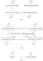
Fig. 7 is a block diagram illustrating a temperature control apparatus according to an exemplary embodiment; -
Fig. 8 is a block diagram illustrating a temperature control apparatus according to another exemplary embodiment; -
Fig. 9 is a block diagram illustrating a temperature control apparatus according to another exemplary embodiment; -
Fig. 10 is a block diagram illustrating a temperature control apparatus according to another exemplary embodiment; -
Fig. 11 is a block diagram illustrating a temperature control apparatus according to another exemplary embodiment; -
Fig. 12 is a block diagram illustrating a temperature control apparatus according to another exemplary embodiment; -
Fig. 13 is a block diagram illustrating a terminal entity according to an exemplary embodiment; -
Fig. 14 is a block diagram illustrating adevice 800 for controlling temperature according to an exemplary embodiment. - Reference will now be made in detail to exemplary embodiments, examples of which are illustrated in the accompanying drawings. The following description refers to the accompanying drawings in which the same numbers in different drawings represent the same or similar elements unless otherwise represented. The implementations set forth in the following description of exemplary embodiments do not represent all implementations consistent with the disclosure. Instead, they are merely examples of apparatuses and methods consistent with aspects related to the disclosure as recited in the appended claims.
-
Fig. 1 is a flow chart showing a temperature control method according to an exemplary embodiment. As shown inFig. 1 , the temperature control method is applied in a terminal and includes followings. - In a block S11, a current state of a user interface (UI for short) of a terminal is determined if a current temperature value of the terminal reaches a predetermined threshold, in which the current state of the UI includes an interacting state and a non-interacting state.
- The terminal determines the current temperature value by continuously detecting temperature values of each heat source in the terminal. For example, the temperature value of the terminal may be detected by placing a corresponding temperature sensor within the terminal. The heat source in the terminal may include a processor, a charging module, a backlight module and the like.
- If the current temperature value of the terminal reaches the predetermined threshold, it is determined whether the user is operating the terminal. It is illustrated that the current state of the UI of the terminal is the interacting state if the user is operating the terminal; otherwise, the current state of the UI of the terminal is the non-interacting state.
- In a block S12, a corresponding temperature control is performed on the terminal according to the current state of the UI.
- That is to say, in combination with the current temperature value and whether the user is operating the terminal, the temperature control is performed on the terminal. The temperature control strategy varies with the current temperature value and current state of the UI.
- In a specific implementation, the terminal may provide a selecting function for determining whether to activate the above temperature control method for the user. The terminal may perform the temperature control method automatically, if the user selects to activate the temperature control method; or, the terminal may automatically perform the temperature control method in a particular period or by being triggered via a particular event, according to a selection of the user.
- In the embodiment, the temperature control is performed according to the current temperature value and the current state of the UI of the terminal. The temperature control strategy varies with the current temperature value and current state of the UI. Thus, the temperature control may be performed on the terminal in combination with an actual usage situation of the terminal such that the usage may not be influenced to a greatest extent when the temperature control is performed, thereby largely improving the user experience.
-
Fig. 2 is a flow chart showing a temperature control method according to another exemplary embodiment. As shown inFig. 2 , the block S12 may specifically include followings. - In a block S21, it is detected whether a screen of the terminal is on.
- Whether the screen of the terminal is on may be determined by detecting that the screen of the terminal is locked or unlocked. The screen of the terminal is on if the screen of the terminal is locked. And the screen of the terminal is off if the screen of the terminal is unlocked.
- Alternatively, whether the screen of the terminal is on may be determined also by detecting that the screen of the terminal is bright or dark. It is determined that the screen of the terminal is on if the screen of the terminal is bright. And it is determined that the screen of the terminal is off if the screen of the terminal is dark.
- Further, on the basis of above judgments, a time factor may be employed. For example, it is determined that the screen of the terminal is off if the screen of the terminal is dark very soon after being bright. Only when a period that the screen of the terminal is unlocked or is bright is greater than a predetermined period, it is determined that the screen of the terminal is on, otherwise, it is determined that the screen of the terminal is off.
- In a block S22, the current state of the UI is determined as the interacting state if the screen of the terminal is on; otherwise, the current state of the UI is determined as the non-interacting state.
- It is illustrated that the user is operating the terminal if the screen is on, and then the current state of the UI may be determined as the interacting terminal.
- It is illustrated that the user is not operating the terminal directly if the screen is off, and then the current state of the UI may be determined as the non-interacting state.
- In a process that the terminal is used by the user, it is common that the user is operating the terminal if the screen of the terminal is unlocked or is bright. Therefore, in the embodiment, whether the screen of the terminal is on is taken as a condition for determining the current state of the UI of the terminal, which may ensure a correctness of determining the current state of the UI.
-
Fig. 3 is a flow chart showing a temperature control method according to another exemplary embodiment. As shown inFig. 3 , the block S12 may specifically includes followings. - In a block S31, it is determined whether there is a touch screen event in the terminal.
- Detecting whether there is a touch screen event is to detect whether the user is touching the screen.
- In a block S32, the current state of the UI is determined as the interacting state if there is the touch screen event in the terminal; otherwise, the current state of the UI is determined as the non-interacting state.
- It may be determined that the user is operating the terminal when the user is touching the screen. Further, the current state of the UI may be determined as the interacting state; otherwise, the current state of the UI may be determined as the non-interacting state.
- In the embodiment, the current state of the UI of the terminal is determined via the touch screen event, which may reflect the current state of the UI of the terminal more directly and more precisely.
-
Fig. 4 is a flow chart showing a temperature control method according to another exemplary embodiment. As shown inFig. 4 , if the current temperature value of the terminal reaches a first predetermined threshold, the block S12 may specifically include followings. - In a block S41, it is judged whether the current state of the UI is the interacting state.
- When the current temperature value reaches the first predetermined threshold, a processor power consumption is not limited directly. It is continuously judged whether the current state of the UI is the interacting state, that is, it is determined whether the user is operating the terminal.
- In a block S42, a screen power consumption is reduced and a charging power consumption is reduced to a predetermined charging power consumption if the current state of the UI is the interacting state.
- When the current temperature value of the terminal reaches the first predetermined threshold, the processor power consumption is not limited if the user is operating the terminal, the screen power consumption and the charging power consumption are reduced such that not only the temperature control but also a normal usage of the terminal by the user are ensured. A premise of reducing the charging power consumption is that the terminal is being charged, that is, if the current state of the UI is the interacting state and the terminal is being charged at the same time, then the charging power consumption is reduced.
- In a block S43, at least one of applications running in the terminal is closed according to a priority list of applications if the current state of the UI is the non-interacting state.
- When the current temperature value of the terminal reaches the first predetermined threshold, the temperature control may be realized by limiting the processor power consumption if the user is not operating the terminal directly. Specifically, several applications running in the terminal may be closed in the priority list such that the processor power consumption may be reduced.
- In the embodiment, if the current temperature value of the terminal reaches a certain degree, different temperature control strategies are performed according to the current states of the UI of the terminal. If the current state of the UI is the interacting state, in order to ensure that a system runs smoothly when the user is operating the terminal, instead of limiting the processor power consumption, the screen power consumption and the charging power consumption are limited to realize the temperature control. If the current state of the UI is the non-interacting state, the processor power consumption may be limited directly to realize the temperature control. Thus, the method realizes the corresponding temperature control according to the actual usage situation such that the usage may not be influenced to a greatest extent when the temperature control is performed, thereby largely improving the user experience.
-
Fig. 5 is a flow chart showing a temperature control method according to another exemplary embodiment. As shown inFig. 5 , when the current temperature value of the terminal reaches a second predetermined threshold, the block S12 may specifically include followings. - In a block S51, it is judged that whether the current state of the UI is the interacting state.
- The second predetermined threshold is greater than the first predetermined threshold.
- When the current temperature reaches the second predetermined threshold, it is illustrated that the temperature value of the terminal reaches a higher level. It may be unable to control the temperature of the terminal into a regular range if the above temperature control strategy is performed. Therefore, a stricter temperature control strategy may be performed.
- In a block S52, the screen power consumption of the terminal is reduced and a charging function of the terminal is closed, if the current state of the UI is the interacting state.
- If the temperature value reaches the higher level while the user is operating the terminal, in order to ensure not only the normal usage of the terminal by the user, but also the temperature control, in addition to reducing the screen power consumption of the terminal, the charging function needs to be closed such that the charging power consumption is reduced to 0 to ensure the temperature control.
- A premise of closing the charging function is that the terminal is being charged, that is, if the current state of the UI is the interacting state and the terminal is being charged, the charging function of the terminal is closed.
- In a block S53, at least one of the applications running in the terminal is closed according to the priority list of applications and a network power consumption of the terminal is reduced to a predetermined network power consumption, if the current state of the UI is the non-interacting state.
- If the temperature value reaches the higher level while the user is not operating the terminal, in addition to closing the applications running in the terminal, the network power consumption needs to be limited. That is, the network function is limited (for example, music or video download via the network is limited) to ensure the temperature control.
- In the embodiment, if the current temperature value of the terminal reaches a certain degree, different temperature control strategies are performed according to the current states of the UI of the terminal. If the current state of the UI is the interacting state, in order to ensure that a system runs smoothly when the user is operating the terminal, instead of limiting the processor power consumption, the screen power consumption is limited and the charging power consumption is closed to realize the temperature control. If the current state of the UI is the non-interacting state, the processor power consumption and the network power consumption may be limited directly to realize the temperature control. Thus, the method realizes the corresponding temperature control according to the actual usage situation such that the usage may not be influenced to a greatest extent when the temperature control is performed, thereby largely improving the user experience.
- In the above embodiments, the priority list of applications has existed when at least one of the applications running in the terminal is closed according to the priority list. That is to say, the priority list needs to be predetermined. The terminal may generate the priority list by defaulted. Or, the priority list may be set by inputting via the user. A latter one may be implemented by a following manner.
-
Fig. 6 is a flow chart showing a temperature control method according to another exemplary embodiment. As shown inFig. 6 , a method for determining the priority list includes followings. - In a block S61, application priority information input by the user is received.
- The terminal may provide a setting function for setting the priority of the applications. For example, the terminal may provide icons or a name list of all applications in the terminal such that the user may input the priority information according to the icons and the name list.
- In a block S62, the priority list of applications is generated according to the application priority information.
- The priority list of applications is configured to indicate a priority order of applications, and at least one of the applications running in the terminal is closed in the priority order from low to high.
- In the embodiment, the application priority information is set by the user such that a result that the terminal closes the applications according to the application priority information may reflect the user's demand accurately. Furthermore, there is not a case that the application considered to be important by the user is closed, thereby improving the user experience.
- In another embodiment, a specific implementation of reducing the screen power consumption of the terminal may include:
- a screen brightness of the terminal is reduced to a predetermined screen brightness; and/or
- a screen key light of the terminal is closed.
- It is to be illustrated that, specific decrease degrees of the screen power consumption are different when the current temperature value reaches the first predetermined threshold or the second predetermined threshold. For example, if the current temperature value reaches the first predetermined threshold, the decrease degree of the screen power consumption is respective small. And if the current temperature value reaches the second predetermined threshold, the decrease degree of the screen power consumption is respective great.
- In the embodiment, the screen power consumption is reduced by reducing the screen brightness of the screen and/or closing the screen key light such that the decrease of the power consumption is realized without influencing the user experience, thereby realizing the temperature control of the terminal.
-
Fig. 7 is a block diagram illustrating a temperature control apparatus according to an exemplary embodiment. As shown inFig. 7 , the apparatus includes a determiningmodule 701 and the controllingmodule 702. - The determining
module 701 is configured to determine a current state of a user interface (UI for short) of a terminal if a current temperature value of the terminal reaches a predetermined threshold, in which the current state of the UI includes an interacting state and a non-interacting state. - The controlling
module 702 is configured to perform a corresponding temperature control on the terminal according to the current state of the UI. -
Fig. 8 is a block diagram illustrating a temperature control apparatus according to another exemplary embodiment. As shown inFig. 8 , the determiningmodule 701 includes a first detecting sub-module 7011 and a first determining sub-module 7012. - The first detecting sub-module 7011 is configured to detect whether a screen of the terminal is on.
- The first determining sub-module 7012 is configured to determine the current state of the UI as the interacting state if the screen of the terminal is on, otherwise, to determine the current state of the UI as the non-interacting state.
-
Fig. 9 is a block diagram illustrating a temperature control apparatus according to another exemplary embodiment. As shown inFig. 9 , the determiningmodule 701 further includes a second detecting sub-module 7013 and a second determining sub-module 7014. - The second detecting sub-module 7013 is configured to detect whether there is a touch screen event in the terminal.
- The second determining sub-module 7014 is configured to determine the current state of the UI as the interacting state if there is the touch screen event in the terminal, otherwise, to determine the current state of the UI as the non-interacting state.
-
Fig. 10 is a block diagram illustrating a temperature control apparatus according to another exemplary embodiment. As shown inFig. 10 , the controllingmodule 702 includes a first controlling sub-module 7021 and a second controlling sub-module 7022. - The first controlling sub-module 7021 is configured to reduce a screen power consumption of the terminal and to reduce a charging power consumption of the terminal to a predetermined charging power consumption if the current state of the UI is the interacting state, when the current temperature value reaches a first predetermined threshold.
- The second controlling sub-module 7022 is configured to close at least one of applications running in the terminal according to a priority list of applications if the current state of the UI is the non-interacting state when the current temperature value reaches a first predetermined threshold.
-
Fig. 11 is a block diagram illustrating a temperature control apparatus according to another exemplary embodiment. As shown inFig. 11 , the controllingmodule 702 further includes a third controlling sub-module 7023 and a fourth controlling sub-module 7024. - The third controlling sub-module 7023 is configured to reduce the screen power consumption of the terminal and to close a charging function of the terminal if the current state of the UI is the interacting state, when the current temperature value reaches a second predetermined threshold.
- The fourth controlling sub-module 7024 is configured to close at least one of the applications running in the terminal according to the priority list of applications and to reduce a network power consumption of the terminal to a predetermined network power consumption if the current state of the UI is the non-interacting state, when the current temperature value reaches a second predetermined threshold.
-
Fig. 12 is a block diagram illustrating a temperature control apparatus according to another exemplary embodiment. As shown inFig. 12 , the controllingmodule 702 includes a receiving sub-module 7025 and a generating sub-module 7026. - The receiving sub-module 7025 is configured to receive application priority information input by a user before the second controlling sub-module or the fourth controlling sub-module closes at least one of the applications running in the terminal according to the priority list of applications.
- The generating sub-module 7026 is configured to generate the priority list of applications according to the application priority information.
- The priority list of applications is configured to indicate a priority order of applications, and at least one of the applications running in the terminal is closed in the priority order from low to high.
- In another embodiment, the first controlling sub-module 7021 is specifically configured to:
- reduce a screen brightness of the terminal to a predetermined screen brightness; and/or
- close a screen key light of the terminal.
- In another embodiment, the third controlling sub-module 7023 is specifically configured to:
- reduce a screen brightness of the terminal to a predetermined screen brightness; and/or
- close a screen key light of the terminal.
- With respect to the apparatuses in the above embodiments, the specific manners for performing operations for individual modules therein have been described in detail in the embodiments regarding the methods, which are not elaborated herein again.
- The above description has described internal functional modules and schematic diagrams of the temperature control apparatus.
Fig. 13 is a block diagram illustrating a terminal entity according to an exemplary embodiment. As shown inFig. 13 , the terminal includes amemory 71 and aprocessing component 72. - The
memory 71 is configured to store an instruction executable by theprocessing component 72. - The
processing component 72 is configured to: - determine a current state of a UI of a terminal if a current temperature value of the terminal reaches a predetermined threshold, in which the current state of the UI includes an interacting state and a non-interacting state; and
- perform a corresponding temperature control on the terminal according to the current state of the UI.
- In the above embodiment of the terminal, it is to be understood that, the
processing component 72 may be a central processing unit (CPU), or may be another general processor, a digital signal processor (DSP), an application specific integrated circuit (ASIC), etc. The general processor may be a microprocessor, or may be other regular processors, etc. And the above memory may be a read-only memory (ROM), a random access memory (RAM), a flash memory, a disk or a solid state disk. A SIM card is known as a user identification card, an intelligent card, and a digital mobile phone provided with the SIM card can be used. That is, the computer chip stores information of a user of the digital mobile phone and content such as an encrypted cipher code and a telephone dictionary etc. The acts in the method disclosed by combining embodiments of the present disclosure may be implemented by a hardware processor or a combination of hardware and software modules in the processor. -
Fig. 14 is a block diagram illustrating adevice 800 for controlling temperature according to an exemplary embodiment. For example, thedevice 800 may be a mobile phone, a computer, a digital broadcasting terminal, a messaging device, a game console, a tablet device, a medical device, fitness equipment, a Personal Digital Assistant PDA, and the like. - Referring to
Fig. 14 , thedevice 800 may include the following one or more components: aprocessing component 802, amemory 804, apower component 806, amultimedia component 808, anaudio component 810, an Input/Output (I/O)interface 812, asensor component 814, and acommunication component 816. - The
processing component 802 typically controls overall operations of thedevice 800, such as the operations associated with display, telephone calls, data communications, camera operations, and recording operations. Theprocessing component 802 may include one ormore processors 820 to execute instructions to perform all or part of the acts in the above described methods. Moreover, theprocessing component 802 may include one or more modules which facilitate the interaction between theprocessing component 802 and other components. For instance, theprocessing component 802 may include a multimedia module to facilitate the interaction between themultimedia component 808 and theprocessing component 802. - The
memory 804 is configured to store various types of data to support the operation of thedevice 800. Examples of such data include instructions for any applications or methods operated on thedevice 800, contact data, phonebook data, messages, pictures, video, etc. Thememory 804 may be implemented using any type of volatile or non-volatile memory devices, or a combination thereof, such as a static random access memory (SRAM), an electrically erasable programmable read-only memory (EEPROM), an erasable programmable read-only memory (EPROM), a programmable read-only memory (PROM), a read-only memory (ROM), a magnetic memory, a flash memory, a magnetic or optical disk. - The
power component 806 provides power to various components of thedevice 800. Thepower component 806 may include a power management system, one or more power sources, and any other components associated with the generation, management, and distribution of power in thedevice 800. - The
multimedia component 808 includes a screen providing an output interface between thedevice 800 and the user. In some embodiments, the screen may include a liquid crystal display (LCD) and a press panel (TP). If the screen includes the press panel, the screen may be implemented as a press screen to receive input signals from the user. The press panel includes one or more press sensors to sense presses, swipes, and other gestures on the press panel. The press sensors may not only sense a boundary of a press or swipe action, but also sense a duration time and a pressure associated with the press or swipe action. In some embodiments, themultimedia component 808 includes a front camera and/or a rear camera. The front camera and/or the rear camera may receive external multimedia data while thedevice 800 is in an operation mode, such as a photographing mode or a video mode. Each of the front camera and the rear camera may be a fixed optical lens system or have focus and optical zoom capability. - The
audio component 810 is configured to output and/or input audio signals. For example, theaudio component 810 includes a microphone (MIC) configured to receive an external audio signal when thedevice 800 is in an operation mode, such as a call mode, a recording mode, and a voice recognition mode. The received audio signal may be further stored in thememory 804 or transmitted via thecommunication component 816. In some embodiments, theaudio component 810 further includes a speaker to output audio signals. - The I/
O interface 812 provides an interface for theprocessing component 802 and peripheral interface modules, such as a keyboard, a click wheel, buttons, and the like. The buttons may include, but are not limited to, a home button, a volume button, a starting button, and a locking button. - The
sensor component 814 includes one or more sensors to provide status assessments of various aspects of thedevice 800. For instance, thesensor component 814 may detect an open/closed status of thedevice 800 and relative positioning of components (e.g. the display and the keypad of the device 800). Thesensor component 814 may also detect a change in position of thedevice 800 or of a component in thedevice 800, a presence or absence of user contact with thedevice 800, an orientation or an acceleration/deceleration of thedevice 800, and a change in temperature of thedevice 800. Thesensor component 814 may include a proximity sensor configured to detect the presence of nearby objects without any physical contact. Thesensor component 814 may also include a light sensor, such as a CMOS or CCD image sensor, for use in imaging applications. In some embodiments, thesensor component 814 may also include an accelerometer sensor, a gyroscope sensor, a magnetic sensor, a pressure sensor, or a temperature sensor. - The
communication component 816 is configured to facilitate wired or wireless communication between thedevice 800 and other devices. Thedevice 800 can access a wireless network based on a communication standard, such as WIFI, 2G, or 3G, or a combination thereof. In one exemplary embodiment, thecommunication component 816 receives a broadcast signal or broadcast associated information from an external broadcast management system via a broadcast channel. In one exemplary embodiment, thecommunication component 816 further includes a near field communication (NFC) module to facilitate short-range communications. For example, the NFC module may be implemented based on a radio frequency identification (RFID) technology, an infrared data association (IrDA) technology, an ultra-wideband (UWB) technology, a Bluetooth (BT) technology, and other technologies. - In exemplary embodiments, the
device 800 may be implemented with one or more application specific integrated circuits (ASICs), digital signal processors (DSPs), digital signal processing devices (DSPDs), programmable logic devices (PLDs), field programmable gate arrays (FPGAs), controllers, micro-controllers, microprocessors, or other electronic components, for performing the above described methods. - In exemplary embodiments, there is also provided a non-transitory computer readable storage medium including instructions, such as the
memory 804 including instructions. The above instructions are executable by theprocessor 820 in thedevice 800, for performing the above-described methods. For example, the non-transitory computer-readable storage medium may be a ROM, a RAM, a CD-ROM, a magnetic tape, a floppy disc, an optical data storage device, and the like. - A non-transitory computer readable storage medium. The non-transitory computer storage medium has one or more modules stored therein and are configured to perform a temperature control method if the one or more modules are executed. The method includes:
- determining a current state of a user interface (UI) of a terminal if a current temperature value of the terminal reaches a predetermined threshold, in which the current state of the UI includes an interacting state and a non-interacting state; and
- performing a corresponding temperature control on the terminal according to the current state of the UI.
- Other embodiments of the disclosure will be apparent to those skilled in the art from consideration of the specification and practice of the disclosure disclosed here. This application is intended to cover any variations, uses, or adaptations of the disclosure following the general principles thereof and including such departures from the present disclosure as come within known or customary practice in the art.
Claims (14)
- A temperature control method, comprising:determining (S11) a current state of a user interface of a terminal if a current temperature value of the terminal reaches a predetermined threshold, wherein the current state of the user interface comprises an interacting state and a non-interacting state; andperforming (S12) a corresponding temperature control on the terminal according to the current state of the user interface.
- The method according to claim 1, wherein determining (S11) a current state of a user interface of a terminal comprises:detecting (S21) whether a screen of the terminal is on; anddetermining (S22) the current state of the user interface as the interacting state if the screen of the terminal is on, otherwise, determining the current state of the user interface as the non-interacting state,and/ordetermining (S11) a current state of a user interface of a terminal comprises:detecting (31) whether there is a touch screen event in the terminal; anddetermining (32) the current state of the user interface as the interacting state if there is the touch screen event in the terminal, otherwise, determining the current state of the user interface as the non-interacting state.
- The method according to claim 1 or 2, wherein if the current temperature value reaches a first predetermined threshold, performing (S12) a corresponding temperature control on the terminal according to the current state of the user interface comprises:reducing (S42) a screen power consumption of the terminal and reducing (S42) a charging power consumption of the terminal to a predetermined charging power consumption, if the current state of the user interface is the interacting state; andclosing (S43) at least one of applications running in the terminal according to a priority list of applications if the current state of the user interface is the non-interacting state.
- The method according to claim 3, wherein if the current temperature value reaches a second predetermined threshold, performing (S12) a corresponding temperature control on the terminal according to the current state of the user interface comprises:reducing (S52) the screen power consumption of the terminal and closing (S52) a charging function of the terminal, if the current state of the user interface is the interacting state; andclosing (S53) at least one of the applications running in the terminal according to the priority list of applications and reducing (S53) a network power consumption of the terminal to a predetermined network power consumption, if the current state of the user interface is the non-interacting state,wherein the second predetermined threshold is greater than the first predetermined threshold.
- The method according to claim 3 or claim 4, wherein before closing at least one of the applications running in the terminal according to the priority list of applications, the method further comprises:receiving (S61) application priority information input by a user; andgenerating (S62) the priority list of applications according to the application priority information,wherein the priority list of applications is configured to indicate a priority order of applications, and at least one of the applications running in the terminal is closed in the priority order from low to high.
- The method according to claim 3 or 4, wherein reducing a screen power consumption of the terminal comprises:reducing a screen brightness of the terminal to a predetermined screen brightness; and/orclosing a screen key light of the terminal.
- A temperature control apparatus, comprising:a determining module (701), configured to determine a current state of a user interface of a terminal if a current temperature value of the terminal reaches a predetermined threshold, wherein the current state of the user interface comprises an interacting state and a non-interacting state; anda controlling module (702), configured to perform a corresponding temperature control on the terminal according to the current state of the user interface.
- The apparatus according to claim 7, wherein the determining module (701) comprises:a first detecting sub-module (7011), configured to detect whether a screen of the terminal is on; anda first determining sub-module (7012), configured to determine the current state of the user interface as the interacting state if the screen of the terminal is on, otherwise, to determine the current state of the user interface as the non-interacting state,and/orthe determining module (701) comprises:a second detecting sub-module (7013), configured to detect whether there is a touch screen event in the terminal; anda second determining sub-module (7014), configured to determine the current state of the user interface as the interacting state if there is the touch screen event in the terminal, otherwise, to determine the current state of the user interface as the non-interacting state.
- The apparatus according to claim 7 or 8, wherein the controlling module (702) comprises:a first controlling sub-module (7021), configured to reduce a screen power consumption of the terminal and to reduce a charging power consumption of the terminal to a predetermined charging power consumption if the current state of the user interface is the interacting state, when the current temperature value reaches a first predetermined threshold; ora second controlling sub-module (7022), configured to close at least one of applications running in the terminal according to a priority list of applications if the current state of the user interface is the non-interacting state, when the current temperature value reaches a first predetermined threshold.
- The apparatus according to claim 9, wherein the controlling module (702) further comprises:a third controlling sub-module (7023), configured to reduce the screen power consumption of the terminal and to close a charging function of the terminal if the current state of the user interface is the interacting state, when the current temperature value reaches a second predetermined threshold; ora fourth controlling sub-module (7024), configured to close at least one of the applications running in the terminal according to the priority list of applications and to reduce a network power consumption of the terminal to a predetermined network power consumption if the current state of the user interface is the non-interacting state, when the current temperature value reaches a second predetermined threshold,wherein the second predetermined threshold is greater than the first predetermined threshold.
- The apparatus according to claim 9 or 10, wherein the controlling module (702) further comprises:a receiving sub-module (7025), configured to receive application priority information input by a user before the second controlling sub-module or the fourth controlling sub-module closes at least one of the applications running in the terminal according to the priority list of applications; anda generating sub-module (7026), configured to generate the priority list of applications according to the application priority information,wherein the priority list of applications is configured to indicate a priority order of applications, and at least one of the applications running in the terminal is closed in the priority order from low to high.
- The apparatus according to claim 9 or 10, wherein the first controlling sub-module (7021) is specifically configured to:reduce a screen brightness of the terminal to a predetermined screen brightness; and/orclose a screen key light of the terminal; and/orthe third controlling sub-module (7023) is specifically configured to:reduce a screen brightness of the terminal to a predetermined screen brightness; and/orclose a screen key light of the terminal.
- A device for controlling temperature, comprising:a processing component (72); anda memory (71), configured to store an instruction executable by the processing component (72);wherein the processing component (72) is configured to perform the temperature control method according to any one of claims 1 to 6.
- A computer-readable storage medium having stored therein instructions that, when executed by a processor of a device, causes the device to perform the temperature control method according to any one of claims 1 to 6.
Applications Claiming Priority (1)
| Application Number | Priority Date | Filing Date | Title |
|---|---|---|---|
| CN201610131244.2A CN105807873B (en) | 2016-03-08 | 2016-03-08 | Temprature control method and device |
Publications (2)
| Publication Number | Publication Date |
|---|---|
| EP3306441A1 true EP3306441A1 (en) | 2018-04-11 |
| EP3306441B1 EP3306441B1 (en) | 2020-06-24 |
Family
ID=56467858
Family Applications (1)
| Application Number | Title | Priority Date | Filing Date |
|---|---|---|---|
| EP16205098.3A Active EP3306441B1 (en) | 2016-03-08 | 2016-12-19 | Temperature control method and apparatus |
Country Status (4)
| Country | Link |
|---|---|
| US (1) | US9860844B2 (en) |
| EP (1) | EP3306441B1 (en) |
| CN (1) | CN105807873B (en) |
| WO (1) | WO2017152621A1 (en) |
Families Citing this family (19)
| Publication number | Priority date | Publication date | Assignee | Title |
|---|---|---|---|---|
| CN105807873B (en) * | 2016-03-08 | 2019-03-08 | 北京小米移动软件有限公司 | Temprature control method and device |
| CN106774744A (en) * | 2016-12-27 | 2017-05-31 | 宇龙计算机通信科技(深圳)有限公司 | A kind of temperature monitoring method and system for mobile terminal |
| CN108604112B (en) * | 2017-01-03 | 2020-07-28 | 华为技术有限公司 | Temperature control method, terminal equipment and device |
| CN107787035B (en) * | 2017-10-31 | 2021-01-08 | 维沃移动通信有限公司 | Mobile communication equipment heating processing method and mobile communication equipment |
| KR102448803B1 (en) | 2018-02-14 | 2022-09-29 | 삼성전자주식회사 | An electronic device obtaining a user input in the water using a pressure sensor and method for controlling the electronic device |
| CN108429309A (en) * | 2018-03-13 | 2018-08-21 | 奇酷互联网络科技(深圳)有限公司 | Charge control method, device, terminal and readable storage medium storing program for executing |
| CN108742174A (en) * | 2018-06-19 | 2018-11-06 | 广东美的厨房电器制造有限公司 | Oven temperature control method, device and computer readable storage medium |
| CN109451155B (en) * | 2018-10-31 | 2020-09-08 | 深圳市网心科技有限公司 | Terminal temperature dynamic control method, terminal, system and storage medium |
| CN110300446B (en) * | 2019-06-28 | 2022-03-22 | 南昌黑鲨科技有限公司 | Network connection control method, system, intelligent terminal and computer readable storage medium |
| CN110649679B (en) * | 2019-10-11 | 2023-06-16 | Oppo广东移动通信有限公司 | Terminal temperature control method, device, equipment and storage medium |
| CN110727561B (en) * | 2019-10-22 | 2023-08-01 | Oppo广东移动通信有限公司 | Abnormal heat dissipation detection method, device, terminal and storage medium |
| US20210258804A1 (en) * | 2020-02-14 | 2021-08-19 | Semiconductor Components Industries, Llc | Adaptive thermal management in wireless communications systems |
| CN111601377B (en) * | 2020-05-15 | 2023-07-25 | 北京小米移动软件有限公司 | Temperature control method, device and storage medium |
| CN112671978B (en) * | 2021-01-05 | 2023-02-24 | 北京小米移动软件有限公司 | Call control method, device and storage medium |
| CN113342082A (en) * | 2021-04-09 | 2021-09-03 | 成都中科创达软件有限公司 | Temperature control method of terminal equipment, and related method and device |
| CN113138854A (en) * | 2021-04-19 | 2021-07-20 | 北京字节跳动网络技术有限公司 | Terminal control method and device, terminal and storage medium |
| CN115484393B (en) * | 2021-06-16 | 2023-11-17 | 荣耀终端有限公司 | Abnormality prompting method and electronic equipment |
| CN114610131A (en) * | 2022-03-18 | 2022-06-10 | Oppo广东移动通信有限公司 | Terminal temperature control method and device, terminal and storage medium |
| CN115150508B (en) * | 2022-05-19 | 2023-10-24 | 东莞市步步高教育软件有限公司 | Video call processing method, device, equipment and storage medium |
Citations (6)
| Publication number | Priority date | Publication date | Assignee | Title |
|---|---|---|---|---|
| US20050246514A1 (en) * | 2004-04-28 | 2005-11-03 | Yoshihiro Nishida | Information processing apparatus and method of system control of the apparatus |
| US20120120625A1 (en) * | 2010-03-08 | 2012-05-17 | Peerless Industries, Inc. | Display Enclosure |
| US20130099569A1 (en) * | 2011-10-24 | 2013-04-25 | Ting-Wei Hsu | Charging control method |
| US20140149753A1 (en) * | 2012-11-27 | 2014-05-29 | Qualcomm Incorporated | Thermal Power Budget Allocation for Maximum User Experience |
| US20150000889A1 (en) * | 2013-06-27 | 2015-01-01 | Motorola Mobility Llc | Electronic system and method for thermal management therein taking into account solar thermal loading |
| US20150181117A1 (en) * | 2013-12-20 | 2015-06-25 | Qualcomm Incorporated | Thermal and power management |
Family Cites Families (12)
| Publication number | Priority date | Publication date | Assignee | Title |
|---|---|---|---|---|
| US7689256B2 (en) * | 2003-11-10 | 2010-03-30 | Research In Motion Limited | Methods and apparatus for limiting communication capabilities in mobile communication devices |
| KR101759941B1 (en) * | 2011-04-21 | 2017-07-31 | 엘지전자 주식회사 | Mobile terminal and method for controlling thereof |
| CN103188388A (en) * | 2011-12-30 | 2013-07-03 | 宇龙计算机通信科技(深圳)有限公司 | Mobile terminal and temperature adjusting method |
| CN103514837B (en) * | 2012-06-27 | 2017-04-12 | 中兴通讯股份有限公司 | Terminal screen backlight control method and apparatus |
| TWI553603B (en) * | 2012-08-27 | 2016-10-11 | 群邁通訊股份有限公司 | Control circuit for backlight modules |
| CN103593032B (en) * | 2013-11-20 | 2019-07-05 | 上海斐讯数据通信技术有限公司 | A kind of electronic equipment and its control method |
| CN103596252B (en) * | 2013-11-28 | 2017-05-24 | 贝壳网际(北京)安全技术有限公司 | Method and device for controlling mobile terminal and mobile terminal |
| CN105323511A (en) * | 2014-07-03 | 2016-02-10 | 日照海帝电器有限公司 | Smart television and temperature control and protection system and method thereof |
| US20160077578A1 (en) * | 2014-09-12 | 2016-03-17 | Mediatek Inc. | Method for controlling an electronic device with aid of thermal detection, and associated apparatus and associated computer program product |
| CN104636236B (en) * | 2014-12-30 | 2017-12-01 | 深圳天珑无线科技有限公司 | The detection method and mobile terminal of the high temperature abnormality of terminal |
| CN104636144A (en) * | 2015-02-26 | 2015-05-20 | 北京数字天域科技有限责任公司 | Background program management method and device of mobile terminal |
| CN105807873B (en) * | 2016-03-08 | 2019-03-08 | 北京小米移动软件有限公司 | Temprature control method and device |
-
2016
- 2016-03-08 CN CN201610131244.2A patent/CN105807873B/en active Active
- 2016-09-28 WO PCT/CN2016/100646 patent/WO2017152621A1/en active Application Filing
- 2016-12-19 EP EP16205098.3A patent/EP3306441B1/en active Active
-
2017
- 2017-01-04 US US15/398,061 patent/US9860844B2/en active Active
Patent Citations (6)
| Publication number | Priority date | Publication date | Assignee | Title |
|---|---|---|---|---|
| US20050246514A1 (en) * | 2004-04-28 | 2005-11-03 | Yoshihiro Nishida | Information processing apparatus and method of system control of the apparatus |
| US20120120625A1 (en) * | 2010-03-08 | 2012-05-17 | Peerless Industries, Inc. | Display Enclosure |
| US20130099569A1 (en) * | 2011-10-24 | 2013-04-25 | Ting-Wei Hsu | Charging control method |
| US20140149753A1 (en) * | 2012-11-27 | 2014-05-29 | Qualcomm Incorporated | Thermal Power Budget Allocation for Maximum User Experience |
| US20150000889A1 (en) * | 2013-06-27 | 2015-01-01 | Motorola Mobility Llc | Electronic system and method for thermal management therein taking into account solar thermal loading |
| US20150181117A1 (en) * | 2013-12-20 | 2015-06-25 | Qualcomm Incorporated | Thermal and power management |
Also Published As
| Publication number | Publication date |
|---|---|
| US20170265141A1 (en) | 2017-09-14 |
| US9860844B2 (en) | 2018-01-02 |
| WO2017152621A1 (en) | 2017-09-14 |
| CN105807873A (en) | 2016-07-27 |
| CN105807873B (en) | 2019-03-08 |
| EP3306441B1 (en) | 2020-06-24 |
Similar Documents
| Publication | Publication Date | Title |
|---|---|---|
| EP3306441A1 (en) | Temperature control method and apparatus | |
| EP3242195A1 (en) | Control implementation method and apparatus for intelligent hardware device | |
| US10610152B2 (en) | Sleep state detection method, apparatus and system | |
| EP3099063A1 (en) | Video communication method and apparatus | |
| EP3176776A1 (en) | Luminance adjusting method and apparatus, computer program and recording medium | |
| EP3300407A1 (en) | Method and device for processing verification code | |
| EP3309672A1 (en) | Method and device for restraining edge touches | |
| EP3136699A1 (en) | Method and device for connecting external equipment | |
| US10444953B2 (en) | View angle switching method and apparatus | |
| CN106357934B (en) | Screen locking control method and device | |
| EP3046212A1 (en) | Method and apparatus for controlling charging of terminal device | |
| US10234924B2 (en) | Method and apparatus for displaying time on mobile device | |
| US10318069B2 (en) | Method for controlling state of touch screen, and electronic device and medium for implementing the same | |
| EP2991067A1 (en) | Backlight brightness control method and device | |
| CN106354504B (en) | Message display method and device | |
| EP3232301B1 (en) | Mobile terminal and virtual key processing method | |
| EP3322227B1 (en) | Methods and apparatuses for controlling wireless connection, computer program and recording medium | |
| RU2665300C2 (en) | Method and device for processing point reporting of touch screen | |
| CN107368175B (en) | Processing method and device for reducing terminal power consumption and terminal | |
| CN105227426B (en) | Application interface switching method and device and terminal equipment | |
| CN105786561B (en) | Method and device for calling process | |
| CN109521923B (en) | Floating window control method and device and storage medium | |
| CN108874450B (en) | Method and device for waking up voice assistant | |
| CN109922203B (en) | Terminal, screen off method and device | |
| CN107682101B (en) | Noise detection method and device and electronic equipment |
Legal Events
| Date | Code | Title | Description |
|---|---|---|---|
| PUAI | Public reference made under article 153(3) epc to a published international application that has entered the european phase |
Free format text: ORIGINAL CODE: 0009012 |
|
| STAA | Information on the status of an ep patent application or granted ep patent |
Free format text: STATUS: THE APPLICATION HAS BEEN PUBLISHED |
|
| AK | Designated contracting states |
Kind code of ref document: A1 Designated state(s): AL AT BE BG CH CY CZ DE DK EE ES FI FR GB GR HR HU IE IS IT LI LT LU LV MC MK MT NL NO PL PT RO RS SE SI SK SM TR |
|
| AX | Request for extension of the european patent |
Extension state: BA ME |
|
| STAA | Information on the status of an ep patent application or granted ep patent |
Free format text: STATUS: REQUEST FOR EXAMINATION WAS MADE |
|
| 17P | Request for examination filed |
Effective date: 20181009 |
|
| RBV | Designated contracting states (corrected) |
Designated state(s): AL AT BE BG CH CY CZ DE DK EE ES FI FR GB GR HR HU IE IS IT LI LT LU LV MC MK MT NL NO PL PT RO RS SE SI SK SM TR |
|
| STAA | Information on the status of an ep patent application or granted ep patent |
Free format text: STATUS: EXAMINATION IS IN PROGRESS |
|
| 17Q | First examination report despatched |
Effective date: 20190102 |
|
| GRAP | Despatch of communication of intention to grant a patent |
Free format text: ORIGINAL CODE: EPIDOSNIGR1 |
|
| STAA | Information on the status of an ep patent application or granted ep patent |
Free format text: STATUS: GRANT OF PATENT IS INTENDED |
|
| INTG | Intention to grant announced |
Effective date: 20200228 |
|
| GRAS | Grant fee paid |
Free format text: ORIGINAL CODE: EPIDOSNIGR3 |
|
| GRAA | (expected) grant |
Free format text: ORIGINAL CODE: 0009210 |
|
| STAA | Information on the status of an ep patent application or granted ep patent |
Free format text: STATUS: THE PATENT HAS BEEN GRANTED |
|
| AK | Designated contracting states |
Kind code of ref document: B1 Designated state(s): AL AT BE BG CH CY CZ DE DK EE ES FI FR GB GR HR HU IE IS IT LI LT LU LV MC MK MT NL NO PL PT RO RS SE SI SK SM TR |
|
| REG | Reference to a national code |
Ref country code: GB Ref legal event code: FG4D |
|
| REG | Reference to a national code |
Ref country code: CH Ref legal event code: EP |
|
| REG | Reference to a national code |
Ref country code: DE Ref legal event code: R096 Ref document number: 602016038623 Country of ref document: DE |
|
| REG | Reference to a national code |
Ref country code: AT Ref legal event code: REF Ref document number: 1284537 Country of ref document: AT Kind code of ref document: T Effective date: 20200715 |
|
| REG | Reference to a national code |
Ref country code: IE Ref legal event code: FG4D |
|
| PG25 | Lapsed in a contracting state [announced via postgrant information from national office to epo] |
Ref country code: GR Free format text: LAPSE BECAUSE OF FAILURE TO SUBMIT A TRANSLATION OF THE DESCRIPTION OR TO PAY THE FEE WITHIN THE PRESCRIBED TIME-LIMIT Effective date: 20200925 Ref country code: NO Free format text: LAPSE BECAUSE OF FAILURE TO SUBMIT A TRANSLATION OF THE DESCRIPTION OR TO PAY THE FEE WITHIN THE PRESCRIBED TIME-LIMIT Effective date: 20200924 Ref country code: SE Free format text: LAPSE BECAUSE OF FAILURE TO SUBMIT A TRANSLATION OF THE DESCRIPTION OR TO PAY THE FEE WITHIN THE PRESCRIBED TIME-LIMIT Effective date: 20200624 Ref country code: LT Free format text: LAPSE BECAUSE OF FAILURE TO SUBMIT A TRANSLATION OF THE DESCRIPTION OR TO PAY THE FEE WITHIN THE PRESCRIBED TIME-LIMIT Effective date: 20200624 Ref country code: FI Free format text: LAPSE BECAUSE OF FAILURE TO SUBMIT A TRANSLATION OF THE DESCRIPTION OR TO PAY THE FEE WITHIN THE PRESCRIBED TIME-LIMIT Effective date: 20200624 |
|
| REG | Reference to a national code |
Ref country code: LT Ref legal event code: MG4D |
|
| PG25 | Lapsed in a contracting state [announced via postgrant information from national office to epo] |
Ref country code: BG Free format text: LAPSE BECAUSE OF FAILURE TO SUBMIT A TRANSLATION OF THE DESCRIPTION OR TO PAY THE FEE WITHIN THE PRESCRIBED TIME-LIMIT Effective date: 20200924 Ref country code: LV Free format text: LAPSE BECAUSE OF FAILURE TO SUBMIT A TRANSLATION OF THE DESCRIPTION OR TO PAY THE FEE WITHIN THE PRESCRIBED TIME-LIMIT Effective date: 20200624 Ref country code: RS Free format text: LAPSE BECAUSE OF FAILURE TO SUBMIT A TRANSLATION OF THE DESCRIPTION OR TO PAY THE FEE WITHIN THE PRESCRIBED TIME-LIMIT Effective date: 20200624 Ref country code: HR Free format text: LAPSE BECAUSE OF FAILURE TO SUBMIT A TRANSLATION OF THE DESCRIPTION OR TO PAY THE FEE WITHIN THE PRESCRIBED TIME-LIMIT Effective date: 20200624 |
|
| REG | Reference to a national code |
Ref country code: NL Ref legal event code: MP Effective date: 20200624 |
|
| REG | Reference to a national code |
Ref country code: AT Ref legal event code: MK05 Ref document number: 1284537 Country of ref document: AT Kind code of ref document: T Effective date: 20200624 |
|
| PG25 | Lapsed in a contracting state [announced via postgrant information from national office to epo] |
Ref country code: NL Free format text: LAPSE BECAUSE OF FAILURE TO SUBMIT A TRANSLATION OF THE DESCRIPTION OR TO PAY THE FEE WITHIN THE PRESCRIBED TIME-LIMIT Effective date: 20200624 Ref country code: AL Free format text: LAPSE BECAUSE OF FAILURE TO SUBMIT A TRANSLATION OF THE DESCRIPTION OR TO PAY THE FEE WITHIN THE PRESCRIBED TIME-LIMIT Effective date: 20200624 |
|
| PG25 | Lapsed in a contracting state [announced via postgrant information from national office to epo] |
Ref country code: CZ Free format text: LAPSE BECAUSE OF FAILURE TO SUBMIT A TRANSLATION OF THE DESCRIPTION OR TO PAY THE FEE WITHIN THE PRESCRIBED TIME-LIMIT Effective date: 20200624 Ref country code: AT Free format text: LAPSE BECAUSE OF FAILURE TO SUBMIT A TRANSLATION OF THE DESCRIPTION OR TO PAY THE FEE WITHIN THE PRESCRIBED TIME-LIMIT Effective date: 20200624 Ref country code: RO Free format text: LAPSE BECAUSE OF FAILURE TO SUBMIT A TRANSLATION OF THE DESCRIPTION OR TO PAY THE FEE WITHIN THE PRESCRIBED TIME-LIMIT Effective date: 20200624 Ref country code: IT Free format text: LAPSE BECAUSE OF FAILURE TO SUBMIT A TRANSLATION OF THE DESCRIPTION OR TO PAY THE FEE WITHIN THE PRESCRIBED TIME-LIMIT Effective date: 20200624 Ref country code: EE Free format text: LAPSE BECAUSE OF FAILURE TO SUBMIT A TRANSLATION OF THE DESCRIPTION OR TO PAY THE FEE WITHIN THE PRESCRIBED TIME-LIMIT Effective date: 20200624 Ref country code: SM Free format text: LAPSE BECAUSE OF FAILURE TO SUBMIT A TRANSLATION OF THE DESCRIPTION OR TO PAY THE FEE WITHIN THE PRESCRIBED TIME-LIMIT Effective date: 20200624 Ref country code: ES Free format text: LAPSE BECAUSE OF FAILURE TO SUBMIT A TRANSLATION OF THE DESCRIPTION OR TO PAY THE FEE WITHIN THE PRESCRIBED TIME-LIMIT Effective date: 20200624 Ref country code: PT Free format text: LAPSE BECAUSE OF FAILURE TO SUBMIT A TRANSLATION OF THE DESCRIPTION OR TO PAY THE FEE WITHIN THE PRESCRIBED TIME-LIMIT Effective date: 20201026 |
|
| PG25 | Lapsed in a contracting state [announced via postgrant information from national office to epo] |
Ref country code: IS Free format text: LAPSE BECAUSE OF FAILURE TO SUBMIT A TRANSLATION OF THE DESCRIPTION OR TO PAY THE FEE WITHIN THE PRESCRIBED TIME-LIMIT Effective date: 20201024 Ref country code: SK Free format text: LAPSE BECAUSE OF FAILURE TO SUBMIT A TRANSLATION OF THE DESCRIPTION OR TO PAY THE FEE WITHIN THE PRESCRIBED TIME-LIMIT Effective date: 20200624 Ref country code: PL Free format text: LAPSE BECAUSE OF FAILURE TO SUBMIT A TRANSLATION OF THE DESCRIPTION OR TO PAY THE FEE WITHIN THE PRESCRIBED TIME-LIMIT Effective date: 20200624 |
|
| REG | Reference to a national code |
Ref country code: DE Ref legal event code: R097 Ref document number: 602016038623 Country of ref document: DE |
|
| PG25 | Lapsed in a contracting state [announced via postgrant information from national office to epo] |
Ref country code: DK Free format text: LAPSE BECAUSE OF FAILURE TO SUBMIT A TRANSLATION OF THE DESCRIPTION OR TO PAY THE FEE WITHIN THE PRESCRIBED TIME-LIMIT Effective date: 20200624 |
|
| PLBE | No opposition filed within time limit |
Free format text: ORIGINAL CODE: 0009261 |
|
| STAA | Information on the status of an ep patent application or granted ep patent |
Free format text: STATUS: NO OPPOSITION FILED WITHIN TIME LIMIT |
|
| 26N | No opposition filed |
Effective date: 20210325 |
|
| REG | Reference to a national code |
Ref country code: CH Ref legal event code: PL |
|
| PG25 | Lapsed in a contracting state [announced via postgrant information from national office to epo] |
Ref country code: MC Free format text: LAPSE BECAUSE OF FAILURE TO SUBMIT A TRANSLATION OF THE DESCRIPTION OR TO PAY THE FEE WITHIN THE PRESCRIBED TIME-LIMIT Effective date: 20200624 Ref country code: SI Free format text: LAPSE BECAUSE OF FAILURE TO SUBMIT A TRANSLATION OF THE DESCRIPTION OR TO PAY THE FEE WITHIN THE PRESCRIBED TIME-LIMIT Effective date: 20200624 |
|
| REG | Reference to a national code |
Ref country code: BE Ref legal event code: MM Effective date: 20201231 |
|
| PG25 | Lapsed in a contracting state [announced via postgrant information from national office to epo] |
Ref country code: LU Free format text: LAPSE BECAUSE OF NON-PAYMENT OF DUE FEES Effective date: 20201219 Ref country code: IE Free format text: LAPSE BECAUSE OF NON-PAYMENT OF DUE FEES Effective date: 20201219 |
|
| PG25 | Lapsed in a contracting state [announced via postgrant information from national office to epo] |
Ref country code: LI Free format text: LAPSE BECAUSE OF NON-PAYMENT OF DUE FEES Effective date: 20201231 Ref country code: CH Free format text: LAPSE BECAUSE OF NON-PAYMENT OF DUE FEES Effective date: 20201231 |
|
| PG25 | Lapsed in a contracting state [announced via postgrant information from national office to epo] |
Ref country code: TR Free format text: LAPSE BECAUSE OF FAILURE TO SUBMIT A TRANSLATION OF THE DESCRIPTION OR TO PAY THE FEE WITHIN THE PRESCRIBED TIME-LIMIT Effective date: 20200624 Ref country code: MT Free format text: LAPSE BECAUSE OF FAILURE TO SUBMIT A TRANSLATION OF THE DESCRIPTION OR TO PAY THE FEE WITHIN THE PRESCRIBED TIME-LIMIT Effective date: 20200624 Ref country code: CY Free format text: LAPSE BECAUSE OF FAILURE TO SUBMIT A TRANSLATION OF THE DESCRIPTION OR TO PAY THE FEE WITHIN THE PRESCRIBED TIME-LIMIT Effective date: 20200624 |
|
| PG25 | Lapsed in a contracting state [announced via postgrant information from national office to epo] |
Ref country code: MK Free format text: LAPSE BECAUSE OF FAILURE TO SUBMIT A TRANSLATION OF THE DESCRIPTION OR TO PAY THE FEE WITHIN THE PRESCRIBED TIME-LIMIT Effective date: 20200624 |
|
| PG25 | Lapsed in a contracting state [announced via postgrant information from national office to epo] |
Ref country code: BE Free format text: LAPSE BECAUSE OF NON-PAYMENT OF DUE FEES Effective date: 20201231 |
|
| P01 | Opt-out of the competence of the unified patent court (upc) registered |
Effective date: 20230523 |
|
| PGFP | Annual fee paid to national office [announced via postgrant information from national office to epo] |
Ref country code: GB Payment date: 20231220 Year of fee payment: 8 |
|
| PGFP | Annual fee paid to national office [announced via postgrant information from national office to epo] |
Ref country code: FR Payment date: 20231222 Year of fee payment: 8 Ref country code: DE Payment date: 20231214 Year of fee payment: 8 |