EP3305479A2 - Adaptateur réglable - Google Patents
Adaptateur réglable Download PDFInfo
- Publication number
- EP3305479A2 EP3305479A2 EP17001663.8A EP17001663A EP3305479A2 EP 3305479 A2 EP3305479 A2 EP 3305479A2 EP 17001663 A EP17001663 A EP 17001663A EP 3305479 A2 EP3305479 A2 EP 3305479A2
- Authority
- EP
- European Patent Office
- Prior art keywords
- adapter
- carriage
- gripping
- locking
- adjustable attachment
- Prior art date
- Legal status (The legal status is an assumption and is not a legal conclusion. Google has not performed a legal analysis and makes no representation as to the accuracy of the status listed.)
- Granted
Links
- 238000006073 displacement reaction Methods 0.000 claims description 6
- 230000000903 blocking effect Effects 0.000 description 9
- 230000005540 biological transmission Effects 0.000 description 5
- 230000006835 compression Effects 0.000 description 2
- 238000007906 compression Methods 0.000 description 2
- MAYZWDRUFKUGGP-VIFPVBQESA-N (3s)-1-[5-tert-butyl-3-[(1-methyltetrazol-5-yl)methyl]triazolo[4,5-d]pyrimidin-7-yl]pyrrolidin-3-ol Chemical compound CN1N=NN=C1CN1C2=NC(C(C)(C)C)=NC(N3C[C@@H](O)CC3)=C2N=N1 MAYZWDRUFKUGGP-VIFPVBQESA-N 0.000 description 1
- 229910000838 Al alloy Inorganic materials 0.000 description 1
- 230000001419 dependent effect Effects 0.000 description 1
- 230000002349 favourable effect Effects 0.000 description 1
- 230000037431 insertion Effects 0.000 description 1
- 238000003780 insertion Methods 0.000 description 1
- 238000007789 sealing Methods 0.000 description 1
- 239000004575 stone Substances 0.000 description 1
Images

Classifications
-
- B—PERFORMING OPERATIONS; TRANSPORTING
- B25—HAND TOOLS; PORTABLE POWER-DRIVEN TOOLS; MANIPULATORS
- B25J—MANIPULATORS; CHAMBERS PROVIDED WITH MANIPULATION DEVICES
- B25J15/00—Gripping heads and other end effectors
- B25J15/02—Gripping heads and other end effectors servo-actuated
- B25J15/0253—Gripping heads and other end effectors servo-actuated comprising parallel grippers
Definitions
- the invention relates to an adjustable attachment adapter for manually displacing a gripping element mounted on a carriage of a gripping device, wherein a carriage adapter is attached to the carriage and a gripping element adapter is attached to the gripping element.
- the present invention is based on the problem to develop an adjustable attachment adapter in conjunction with a gripping device for large clamping forces whose gripping or forceps width is easily adjustable.
- a carriage adapter is attached to the carriage and a gripping element adapter is attached to the gripper element.
- a gripping element adapter is attached to the gripper element.
- Between the carriage adapter and the Greifimplantationadapter is at least one positive, arranged by a linear manual sliding movement against a spring force latched latch or Zahnrichtgesperre.
- the bar or Zahnrichtgesperre has a blocker, which cooperates to change the gripping or forceps width of the gripping device with a locking piece, which has in Einstellsverschiebecardi successively more evenly or non-uniformly divided locking or recesses.
- the one or more attachment adapters it is possible to manually increase the regular workpiece clamping range of a gripping device, for example by several times.
- the larger components of the attachment adapters are made of an aluminum alloy.
- the carriages are driven, for example, by means of three gears arranged in series, for example a spur gear, a worm gear and a rack gear.
- gears arranged in series, for example a spur gear, a worm gear and a rack gear.
- sliding wedge gearing curved, lever, slide or traction mechanism transmissions.
- the solution of the problem is transferable to an angle gripper.
- the slidably guided in the main body of the gripping device carriage is replaced by a gripping element-carrying pivot arm which is pivotally mounted in the base body in a pivot joint.
- On the swivel arm of the carriage adapter is attached here.
- the carriage adapter may be a relatively short nut-like body on which the gripping element adapter is slidably seated in the form of a long guide rail.
- the Schittenadapter and the Greifimplantationadapter each have two locking systems, in each of which a locker in each side cheek of serving as a locking piece guide attachment in one of a plurality of locking recesses is locked or latched.
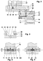
- FIGS. 1 and 2 show a parallel gripper device with two each on slide (15) seated jaws (1, 2).
- the carriages (15), which are movable in their longitudinal direction, are guided, for example, in a sliding manner in a base body (11) in a guide groove (12).
- the guide body (12) receiving the base body (11) further surrounds an example double-acting cylinder-piston unit (25).
- the cylinder-piston unit acts on the carriages (15) via a double-spline wedge mechanism (20).
- an adjustable attachment adapter (30) is attached on each carriage (15) on each carriage (15) on each carriage (15) an adjustable attachment adapter (30) is attached. The latter carries the manually displaceable on it gripping elements (1, 2).
- the FIG. 2 represents the left half of the parallel gripping device in partial longitudinal section.
- the gripping jaw (1) is in the open position.
- the substantially cuboid base body (11) of the parallel gripper device consists of an upper guide section and a lower drive section.
- the length of the base body (11) is for example almost twice as long as its width and the body height.
- the guide section centrally accommodates the guide groove (12) which is open towards the top - towards the gripping elements (1, 2) and which, for example, has a rectangular cross section. In the side walls of the guide groove (12), for example, separate guide rails are incorporated.
- the drive section located below the guide section essentially accommodates the cylinder-piston unit (25).
- an oval cylindrical recess (13) projects into the base body (11) in the direction of the guide groove (12), cf. FIG. 2 .
- a through hole which connects the cylinder recess (13) with the guide groove (12).
- the through hole has a recess for receiving a piston rod sealing ring.
- an oval piston (26) with its piston rod (27) is arranged in the cylinder recess (13), which is tightly closed by a cover.
- the piston rod (27) is screwed to the piston (26).
- the piston (26) and the double slide wedge (21) of the double slide wedge gear (20) together form a dimensionally stable assembly.
- the double slide wedge (21) is arranged in the guide groove (12) as part of a double slide wedge gear (20). He has at its front ends in each case a beveled wedge angle in the end face, which is in each case part of a T-shaped wedge web. Each of the two wedge webs of the double slip wedge (21) engages positively in a carriage (15) mounted in the guide groove (12).
- Each carriage (15) is primarily a cuboid body.
- a bevelled end face a Keilstegnut for receiving the respective wedge web of the double slide wedge (21) is provided.
- On both sides are e.g. each incorporated two Schlitten Adjustsnuten in the carriage. With these grooves, the single carriage (15) is slidably mounted on the guide rails.
- each carriage (15) On top of each carriage (15) is an e.g. cuboidal elevation which, when the carriage (15) is mounted at the top, can be increased by e.g. 1.2 mm - projecting beyond the top of the main body - protruding from the guide groove (12).
- the flat top of the elevation has two threaded bores equipped with cylinder countersinks to which the gripping jaws (1, 2) are releasably attached. Centering sleeves for precise, at least form-fitting positioning of the guide attachment (32) of the attachment adapter (30) on the carriage (15) are located in the cylinder counterbores.
- the slides (15) are here in the guide groove (12), see. FIG. 1, arranged one behind the other, so that their mutually facing end faces contact or at least almost touch each other with a minimal gripping jaw spacing.
- the middle region of the slot opening of the guide groove (12) is closed with a rectangular cover plate, for example.
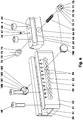
- the attachment adapter comprises two larger components, a carriage adapter (31) and a gripper element adapter (61) carried by it.
- the carriage adapter (31) is a guide attachment (32) in the form of a guide rail.
- a guide attachment 32) in the form of a guide rail.
- FIG. 3 which is for example 29 mm in the lower region and, for example, 20 mm in the upper, narrower region.
- the plate-like base part (33) on both sides of which the Greifelemeteadapter (61) partially encompassing side cheeks (34, 35) are integrally formed.
- the base part (33) with which the guide attachment (32) is fastened to the respective carriage (15) has in its two end regions in each case two fastening bores (37) arranged one behind the other along the longitudinal direction.
- the center lines of both holes (37) lie on the vertical central longitudinal plane (8) of the gripping device (10).
- the distance between the holes (37) is 24 mm.
- the outer bore (37) of the after FIG. 1 front hole group has the next component front side a distance of 9.1 mm, while the outer bore (37) of the after FIG. 1 rear hole group to the nearest end face of the guide attachment (32) is 13 mm. All four holes (37) are equipped on both sides to accommodate centering sleeves or screw heads with cylindrical countersinks.
- Both side cheeks (34, 35) have a row locking recess (51).
- the latter are mirror-symmetrical with respect to the vertical center longitudinal plane (8).
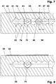
- the row-locking recess (51) is a superimposition of a displacement recess (52), in FIG FIG. 7 shown in dashed lines, and a plurality of in the same division (58) juxtaposed Einzelelsperrausappellus (53). According to the embodiment, there are 11 EinzelelsperrausNeill (53) with a pitch (58) of 7 mm.
- the row locking recess (51) has a center line (47) parallel to the carriage traversing direction (9), which lies, for example, halfway between the bottom (41) of the guide groove (36) and the wrap flank (42) of the side cheeks (34, 35), cf.
- a numbering is arranged above the row locking recess (51), which assigns a number to each individual locking recess (53).
- the sliding recess (52), which makes it possible to move the gripping element adapter (61) by means of the actuating elements (100) along the entire row locking recess (51), has e.g. a height of 4.6 mm.
- the Einzelperperrausoutlinedung (53) has in the plane of FIG. 7 the diamond-shaped cross-section (91) having a square surface.
- Each linear cross-sectional edge represents a plane blocking flank (55, 56).
- Two adjacent blocking flanks pass over a rounding (57), which for example has a 2.1 mm radius.
- the blocking flanks (55, 56) have a load-bearing length of 2.15 mm along the straight cross-sectional edge here.
- a tooth (99) of the row locking recess (51) is formed.
- the contour of the row locking recess (51) is chamfered along the inner side edges (38) of the guide groove (36).
- the four vertical edges of the guide attachment (32) are rounded here with a 5 mm radius.
- the sliding carriage (62) is essentially a cuboid, for example, 52 mm long and 27 mm wide body, which is mirror-symmetrical to the vertical center longitudinal plane (8). Its maximum height is 17.6 mm.
- T-slot sliding carriage (62) on both sides, for example, a 6.6 mm high Umgreifabsatz (63).
- the sliding carriage (62) has two fastening threaded bores (64) to the center line (7).
- the fastening threaded holes (64) have cylindrical countersinks on both sides and a distance of eg 24 mm.
- the gripping elements (1, 2) on the sliding carriage (62) with the interposition of centering sleeves by means of screws (49) attached.
- a stepped bore (65) which is after FIGS. 2, 4 and 5 in the lower part, for example, has an M3 thread.
- the upper area has a diameter of 3 or 4 mm.
- a finely machined guide bore (66) which is oriented perpendicular to the center line (7) and perpendicular to the gripping direction (9).
- the guide bore (66) opens the stepped bore (65).
- a threaded pin (67) is screwed, the pin (68), for example, 0.8 mm in the guide bore (66) projects as a stop.
- the set screw (67) in its rear, the pin (68) facing away from a widening over which it rests as a depth stop on a - located between the upper and the lower stepped bore portion of the stepped bore (65) - Federal.
- the four vertical edges of the guide attachment (32) are e.g. rounded with a 4 mm radius.
- the single, one-piece blocker (71, 72) consists of a cylindrical sliding piece (73) and a locking piece (75).
- the sliding piece (73) slidably fitted in the guide bore (66) with a small clearance has, for example, a length of 7.3 mm at a diameter of 8.87 mm. It has a flat face, in which a 7 mm deep blind hole hole is incorporated. The latter is used with an inner diameter of 5 mm as a spring guide bore (74).
- the molded on the sliding piece (73), e.g. 6 mm long locking piece (75) is a square, whose theoretical edge lengths measure 7.5 mm.
- the longitudinal edges of the square are e.g. rounded off with a 2.1 mm radius.
- the end face is provided around it with a 0.5 * 30 ° Rast Koreanfrontfase (77), which guarantees easy insertion into a Einzelsperraus Principleung (53).
- In the center of the end face is a e.g. 3 mm deep M3 threaded hole (78), in which the actuator (100) can be accommodated.
- a helical compression spring (87) is arranged, which is supported on the two bottoms of the spring guide bores (74).
- a flat stop collar (79) which consists of four circular sections here.
- the detachable one-piece actuators (100) are e.g. Rotary parts, consisting of an actuator (101), an operating shaft (102) and an M3 external thread.
- the disc-shaped actuator (101) has e.g. with a width of 5 mm an ergonomically favorable diameter of 13 mm.
- the e.g. 9.5 mm long cylindrical shaft (102) has a diameter of 3 mm.
- the actuating elements (100) are screwed into the actuating threaded bores (78) of the blocking devices (71, 72).
- the respective catcher (71, 72) does not rotate in the guide bore (66) of the sliding carriage (62).
- both locking pieces (75) are completely unlocked from the individual locking recesses (53) which have been stored so far.
- the inner end faces of the blocker (71, 72) come here on the pin (68) of the threaded pin (67) to the plant.
- the actuating elements (100) are released. Under the pressure of the locking spring (87) the locking pieces (75) are inserted into the new Einzelsperraus Principleung (53). Thereafter, the sliding carriage (62) is locked in the guide attachment (32). Finally, the actuators (100) from the blockers (71, 72) are unscrewed.
Landscapes
- Engineering & Computer Science (AREA)
- Robotics (AREA)
- Mechanical Engineering (AREA)
- Manipulator (AREA)
- Surgical Instruments (AREA)
- Gripping Jigs, Holding Jigs, And Positioning Jigs (AREA)
Applications Claiming Priority (1)
| Application Number | Priority Date | Filing Date | Title |
|---|---|---|---|
| DE102016011975.6A DE102016011975B4 (de) | 2016-10-10 | 2016-10-10 | Einstellbarer Aufsatzadapter |
Publications (3)
| Publication Number | Publication Date |
|---|---|
| EP3305479A2 true EP3305479A2 (fr) | 2018-04-11 |
| EP3305479A3 EP3305479A3 (fr) | 2018-04-25 |
| EP3305479B1 EP3305479B1 (fr) | 2021-03-31 |
Family
ID=60119764
Family Applications (1)
| Application Number | Title | Priority Date | Filing Date |
|---|---|---|---|
| EP17001663.8A Active EP3305479B1 (fr) | 2016-10-10 | 2017-10-10 | Adaptateur réglable |
Country Status (2)
| Country | Link |
|---|---|
| EP (1) | EP3305479B1 (fr) |
| DE (1) | DE102016011975B4 (fr) |
Cited By (5)
| Publication number | Priority date | Publication date | Assignee | Title |
|---|---|---|---|---|
| CN108788290A (zh) * | 2018-06-25 | 2018-11-13 | 上海杨岐视觉机器人有限公司 | 一种剪板的对中式机器人手爪 |
| CN108788291A (zh) * | 2018-06-25 | 2018-11-13 | 上海杨岐视觉机器人有限公司 | 一种剪板的滑槽式机器人手爪 |
| CN110722555A (zh) * | 2019-10-15 | 2020-01-24 | 深圳市佳士机器人科技有限公司 | 一种工业机器人 |
| CN114248292A (zh) * | 2020-09-21 | 2022-03-29 | 上银科技股份有限公司 | 夹爪装置 |
| US11850734B2 (en) | 2020-09-09 | 2023-12-26 | Hiwin Technologies Corp. | Gripper device |
Families Citing this family (1)
| Publication number | Priority date | Publication date | Assignee | Title |
|---|---|---|---|---|
| DE102021212311A1 (de) | 2021-11-02 | 2023-05-04 | Festo Se & Co. Kg | Greifsystem und Verfahren zum Betreiben eines an einem Industrieroboter angebrachten Greifsystems |
Family Cites Families (9)
| Publication number | Priority date | Publication date | Assignee | Title |
|---|---|---|---|---|
| DD252343B1 (de) | 1986-09-01 | 1989-06-07 | Werkzeugmasch Okt Veb | Einrichtung zum automatischen wechsel von greiforganen |
| DE3715140A1 (de) | 1987-05-07 | 1988-11-24 | Preh Indausruestung Gmbh | Handhabungseinrichtung |
| US5924684A (en) | 1997-10-21 | 1999-07-20 | Cheng; Wen-He | Worktable |
| DE102004054177B3 (de) | 2004-11-10 | 2006-04-27 | Schunk Gmbh & Co. Kg Fabrik Für Spann- Und Greifwerkzeuge | Spann- oder Greifvorrichtung, insbesondere Linear- oder Zentrischgreifer |
| JP5397833B2 (ja) * | 2009-04-17 | 2014-01-22 | 株式会社Ihi | 長ストロークロボットハンド |
| JP2011156649A (ja) | 2010-02-04 | 2011-08-18 | Yaskawa Electric Corp | グリッパ装置およびそのストローク量変更方法 |
| DE102010020653B4 (de) | 2010-05-06 | 2015-02-12 | Schunk Gmbh & Co. Kg Spann- Und Greiftechnik | Schlittenarretierung und Greifeinrichtung mit Schlittenarretierung |
| DE102013019034B4 (de) * | 2013-11-15 | 2019-05-09 | Günther Zimmer | Greifvorrichtung mit separaten Führungsschienen |
| DE102013020490B4 (de) | 2013-12-11 | 2018-10-11 | Günther Zimmer | Antriebsvorrichtung für eine Greifvorrichtung |
-
2016
- 2016-10-10 DE DE102016011975.6A patent/DE102016011975B4/de active Active
-
2017
- 2017-10-10 EP EP17001663.8A patent/EP3305479B1/fr active Active
Cited By (6)
| Publication number | Priority date | Publication date | Assignee | Title |
|---|---|---|---|---|
| CN108788290A (zh) * | 2018-06-25 | 2018-11-13 | 上海杨岐视觉机器人有限公司 | 一种剪板的对中式机器人手爪 |
| CN108788291A (zh) * | 2018-06-25 | 2018-11-13 | 上海杨岐视觉机器人有限公司 | 一种剪板的滑槽式机器人手爪 |
| CN110722555A (zh) * | 2019-10-15 | 2020-01-24 | 深圳市佳士机器人科技有限公司 | 一种工业机器人 |
| US11850734B2 (en) | 2020-09-09 | 2023-12-26 | Hiwin Technologies Corp. | Gripper device |
| CN114248292A (zh) * | 2020-09-21 | 2022-03-29 | 上银科技股份有限公司 | 夹爪装置 |
| CN114248292B (zh) * | 2020-09-21 | 2024-03-22 | 上银科技股份有限公司 | 夹爪装置 |
Also Published As
| Publication number | Publication date |
|---|---|
| DE102016011975A1 (de) | 2018-04-12 |
| EP3305479A3 (fr) | 2018-04-25 |
| DE102016011975B4 (de) | 2024-02-22 |
| EP3305479B1 (fr) | 2021-03-31 |
Similar Documents
| Publication | Publication Date | Title |
|---|---|---|
| EP3305479B1 (fr) | Adaptateur réglable | |
| EP1263554B1 (fr) | Pince parallele | |
| EP0595074A1 (fr) | Dispositif de serrage | |
| DE1946651C3 (de) | Spanner für endlose Zugmittel, insbesondere für Ketten | |
| DE3136440A1 (de) | Spannvorrichtung zum spannen von werkzeugen | |
| DE102016218298B4 (de) | Greifvorrichtung | |
| EP3305480B1 (fr) | Adaptateur à blocage rapide doté d'une interface pour éléments de préhension | |
| DE889106C (de) | Verstellbare Reibahle oder Bohrstange | |
| EP3563990B1 (fr) | Dispositif de préhension à élément cunéiforme coulissant double ii optimisé | |
| EP2998068B1 (fr) | Étau de centrage doté de mors a changement rapide | |
| EP0195184B1 (fr) | Dispositif d'interchange de mors | |
| EP3563973B1 (fr) | Pince | |
| EP1245346A1 (fr) | Pince de préhension à machoires parallèles actionnées par deux vérins | |
| DE3732695C1 (de) | Handwerkzeug | |
| DE10302255A1 (de) | Mehrfachspanner | |
| EP0837253B1 (fr) | Dispositif de raccordement pour éléments profilés | |
| DE1750244A1 (de) | Vorrichtung zum Einstellen eines Spieles zwischen zwei Koerpern | |
| DE4229221C2 (de) | Zange mit verstellbarer Maulweite | |
| DE202010001548U1 (de) | Spindel-Mutter-Getriebe und Lineareinheit mit einem solchen Getriebe | |
| DE19955289C2 (de) | Buchsenziehvorrichtung | |
| DE3943134A1 (de) | Klemmvorrichtung fuer ein an einer fuehrung verschiebbares teil | |
| EP1602446A2 (fr) | Dispositif de serrage | |
| DE3136472C2 (fr) | ||
| DE102008045975A1 (de) | Spannvorrichtung | |
| DE202004008799U1 (de) | Spannvorrichtung |
Legal Events
| Date | Code | Title | Description |
|---|---|---|---|
| PUAI | Public reference made under article 153(3) epc to a published international application that has entered the european phase |
Free format text: ORIGINAL CODE: 0009012 |
|
| STAA | Information on the status of an ep patent application or granted ep patent |
Free format text: STATUS: THE APPLICATION HAS BEEN PUBLISHED |
|
| PUAL | Search report despatched |
Free format text: ORIGINAL CODE: 0009013 |
|
| AK | Designated contracting states |
Kind code of ref document: A2 Designated state(s): AL AT BE BG CH CY CZ DE DK EE ES FI FR GB GR HR HU IE IS IT LI LT LU LV MC MK MT NL NO PL PT RO RS SE SI SK SM TR |
|
| AX | Request for extension of the european patent |
Extension state: BA ME |
|
| AK | Designated contracting states |
Kind code of ref document: A3 Designated state(s): AL AT BE BG CH CY CZ DE DK EE ES FI FR GB GR HR HU IE IS IT LI LT LU LV MC MK MT NL NO PL PT RO RS SE SI SK SM TR |
|
| AX | Request for extension of the european patent |
Extension state: BA ME |
|
| RIC1 | Information provided on ipc code assigned before grant |
Ipc: B25J 15/02 20060101AFI20180316BHEP |
|
| STAA | Information on the status of an ep patent application or granted ep patent |
Free format text: STATUS: REQUEST FOR EXAMINATION WAS MADE |
|
| 17P | Request for examination filed |
Effective date: 20181010 |
|
| RBV | Designated contracting states (corrected) |
Designated state(s): AL AT BE BG CH CY CZ DE DK EE ES FI FR GB GR HR HU IE IS IT LI LT LU LV MC MK MT NL NO PL PT RO RS SE SI SK SM TR |
|
| GRAP | Despatch of communication of intention to grant a patent |
Free format text: ORIGINAL CODE: EPIDOSNIGR1 |
|
| STAA | Information on the status of an ep patent application or granted ep patent |
Free format text: STATUS: GRANT OF PATENT IS INTENDED |
|
| INTG | Intention to grant announced |
Effective date: 20201102 |
|
| GRAS | Grant fee paid |
Free format text: ORIGINAL CODE: EPIDOSNIGR3 |
|
| GRAA | (expected) grant |
Free format text: ORIGINAL CODE: 0009210 |
|
| STAA | Information on the status of an ep patent application or granted ep patent |
Free format text: STATUS: THE PATENT HAS BEEN GRANTED |
|
| AK | Designated contracting states |
Kind code of ref document: B1 Designated state(s): AL AT BE BG CH CY CZ DE DK EE ES FI FR GB GR HR HU IE IS IT LI LT LU LV MC MK MT NL NO PL PT RO RS SE SI SK SM TR |
|
| REG | Reference to a national code |
Ref country code: GB Ref legal event code: FG4D Free format text: NOT ENGLISH Ref country code: CH Ref legal event code: EP |
|
| REG | Reference to a national code |
Ref country code: DE Ref legal event code: R096 Ref document number: 502017009853 Country of ref document: DE Ref country code: AT Ref legal event code: REF Ref document number: 1376421 Country of ref document: AT Kind code of ref document: T Effective date: 20210415 |
|
| REG | Reference to a national code |
Ref country code: IE Ref legal event code: FG4D Free format text: LANGUAGE OF EP DOCUMENT: GERMAN |
|
| REG | Reference to a national code |
Ref country code: LT Ref legal event code: MG9D |
|
| PG25 | Lapsed in a contracting state [announced via postgrant information from national office to epo] |
Ref country code: BG Free format text: LAPSE BECAUSE OF FAILURE TO SUBMIT A TRANSLATION OF THE DESCRIPTION OR TO PAY THE FEE WITHIN THE PRESCRIBED TIME-LIMIT Effective date: 20210630 Ref country code: HR Free format text: LAPSE BECAUSE OF FAILURE TO SUBMIT A TRANSLATION OF THE DESCRIPTION OR TO PAY THE FEE WITHIN THE PRESCRIBED TIME-LIMIT Effective date: 20210331 Ref country code: FI Free format text: LAPSE BECAUSE OF FAILURE TO SUBMIT A TRANSLATION OF THE DESCRIPTION OR TO PAY THE FEE WITHIN THE PRESCRIBED TIME-LIMIT Effective date: 20210331 Ref country code: NO Free format text: LAPSE BECAUSE OF FAILURE TO SUBMIT A TRANSLATION OF THE DESCRIPTION OR TO PAY THE FEE WITHIN THE PRESCRIBED TIME-LIMIT Effective date: 20210630 |
|
| PG25 | Lapsed in a contracting state [announced via postgrant information from national office to epo] |
Ref country code: RS Free format text: LAPSE BECAUSE OF FAILURE TO SUBMIT A TRANSLATION OF THE DESCRIPTION OR TO PAY THE FEE WITHIN THE PRESCRIBED TIME-LIMIT Effective date: 20210331 Ref country code: LV Free format text: LAPSE BECAUSE OF FAILURE TO SUBMIT A TRANSLATION OF THE DESCRIPTION OR TO PAY THE FEE WITHIN THE PRESCRIBED TIME-LIMIT Effective date: 20210331 Ref country code: SE Free format text: LAPSE BECAUSE OF FAILURE TO SUBMIT A TRANSLATION OF THE DESCRIPTION OR TO PAY THE FEE WITHIN THE PRESCRIBED TIME-LIMIT Effective date: 20210331 |
|
| REG | Reference to a national code |
Ref country code: NL Ref legal event code: MP Effective date: 20210331 |
|
| PG25 | Lapsed in a contracting state [announced via postgrant information from national office to epo] |
Ref country code: EE Free format text: LAPSE BECAUSE OF FAILURE TO SUBMIT A TRANSLATION OF THE DESCRIPTION OR TO PAY THE FEE WITHIN THE PRESCRIBED TIME-LIMIT Effective date: 20210331 Ref country code: CZ Free format text: LAPSE BECAUSE OF FAILURE TO SUBMIT A TRANSLATION OF THE DESCRIPTION OR TO PAY THE FEE WITHIN THE PRESCRIBED TIME-LIMIT Effective date: 20210331 Ref country code: LT Free format text: LAPSE BECAUSE OF FAILURE TO SUBMIT A TRANSLATION OF THE DESCRIPTION OR TO PAY THE FEE WITHIN THE PRESCRIBED TIME-LIMIT Effective date: 20210331 Ref country code: SM Free format text: LAPSE BECAUSE OF FAILURE TO SUBMIT A TRANSLATION OF THE DESCRIPTION OR TO PAY THE FEE WITHIN THE PRESCRIBED TIME-LIMIT Effective date: 20210331 Ref country code: NL Free format text: LAPSE BECAUSE OF FAILURE TO SUBMIT A TRANSLATION OF THE DESCRIPTION OR TO PAY THE FEE WITHIN THE PRESCRIBED TIME-LIMIT Effective date: 20210331 |
|
| PG25 | Lapsed in a contracting state [announced via postgrant information from national office to epo] |
Ref country code: PT Free format text: LAPSE BECAUSE OF FAILURE TO SUBMIT A TRANSLATION OF THE DESCRIPTION OR TO PAY THE FEE WITHIN THE PRESCRIBED TIME-LIMIT Effective date: 20210802 Ref country code: PL Free format text: LAPSE BECAUSE OF FAILURE TO SUBMIT A TRANSLATION OF THE DESCRIPTION OR TO PAY THE FEE WITHIN THE PRESCRIBED TIME-LIMIT Effective date: 20210331 Ref country code: RO Free format text: LAPSE BECAUSE OF FAILURE TO SUBMIT A TRANSLATION OF THE DESCRIPTION OR TO PAY THE FEE WITHIN THE PRESCRIBED TIME-LIMIT Effective date: 20210331 Ref country code: SK Free format text: LAPSE BECAUSE OF FAILURE TO SUBMIT A TRANSLATION OF THE DESCRIPTION OR TO PAY THE FEE WITHIN THE PRESCRIBED TIME-LIMIT Effective date: 20210331 Ref country code: IS Free format text: LAPSE BECAUSE OF FAILURE TO SUBMIT A TRANSLATION OF THE DESCRIPTION OR TO PAY THE FEE WITHIN THE PRESCRIBED TIME-LIMIT Effective date: 20210731 |
|
| REG | Reference to a national code |
Ref country code: DE Ref legal event code: R097 Ref document number: 502017009853 Country of ref document: DE |
|
| PG25 | Lapsed in a contracting state [announced via postgrant information from national office to epo] |
Ref country code: ES Free format text: LAPSE BECAUSE OF FAILURE TO SUBMIT A TRANSLATION OF THE DESCRIPTION OR TO PAY THE FEE WITHIN THE PRESCRIBED TIME-LIMIT Effective date: 20210331 Ref country code: DK Free format text: LAPSE BECAUSE OF FAILURE TO SUBMIT A TRANSLATION OF THE DESCRIPTION OR TO PAY THE FEE WITHIN THE PRESCRIBED TIME-LIMIT Effective date: 20210331 Ref country code: AL Free format text: LAPSE BECAUSE OF FAILURE TO SUBMIT A TRANSLATION OF THE DESCRIPTION OR TO PAY THE FEE WITHIN THE PRESCRIBED TIME-LIMIT Effective date: 20210331 |
|
| PLBE | No opposition filed within time limit |
Free format text: ORIGINAL CODE: 0009261 |
|
| STAA | Information on the status of an ep patent application or granted ep patent |
Free format text: STATUS: NO OPPOSITION FILED WITHIN TIME LIMIT |
|
| 26N | No opposition filed |
Effective date: 20220104 |
|
| REG | Reference to a national code |
Ref country code: CH Ref legal event code: PL |
|
| PG25 | Lapsed in a contracting state [announced via postgrant information from national office to epo] |
Ref country code: IS Free format text: LAPSE BECAUSE OF FAILURE TO SUBMIT A TRANSLATION OF THE DESCRIPTION OR TO PAY THE FEE WITHIN THE PRESCRIBED TIME-LIMIT Effective date: 20210731 |
|
| REG | Reference to a national code |
Ref country code: BE Ref legal event code: MM Effective date: 20211031 |
|
| PG25 | Lapsed in a contracting state [announced via postgrant information from national office to epo] |
Ref country code: MC Free format text: LAPSE BECAUSE OF FAILURE TO SUBMIT A TRANSLATION OF THE DESCRIPTION OR TO PAY THE FEE WITHIN THE PRESCRIBED TIME-LIMIT Effective date: 20210331 |
|
| PG25 | Lapsed in a contracting state [announced via postgrant information from national office to epo] |
Ref country code: LU Free format text: LAPSE BECAUSE OF NON-PAYMENT OF DUE FEES Effective date: 20211010 Ref country code: BE Free format text: LAPSE BECAUSE OF NON-PAYMENT OF DUE FEES Effective date: 20211031 |
|
| PG25 | Lapsed in a contracting state [announced via postgrant information from national office to epo] |
Ref country code: LI Free format text: LAPSE BECAUSE OF NON-PAYMENT OF DUE FEES Effective date: 20211031 Ref country code: CH Free format text: LAPSE BECAUSE OF NON-PAYMENT OF DUE FEES Effective date: 20211031 |
|
| PG25 | Lapsed in a contracting state [announced via postgrant information from national office to epo] |
Ref country code: IE Free format text: LAPSE BECAUSE OF NON-PAYMENT OF DUE FEES Effective date: 20211010 |
|
| PG25 | Lapsed in a contracting state [announced via postgrant information from national office to epo] |
Ref country code: HU Free format text: LAPSE BECAUSE OF FAILURE TO SUBMIT A TRANSLATION OF THE DESCRIPTION OR TO PAY THE FEE WITHIN THE PRESCRIBED TIME-LIMIT; INVALID AB INITIO Effective date: 20171010 |
|
| PG25 | Lapsed in a contracting state [announced via postgrant information from national office to epo] |
Ref country code: CY Free format text: LAPSE BECAUSE OF FAILURE TO SUBMIT A TRANSLATION OF THE DESCRIPTION OR TO PAY THE FEE WITHIN THE PRESCRIBED TIME-LIMIT Effective date: 20210331 |
|
| PG25 | Lapsed in a contracting state [announced via postgrant information from national office to epo] |
Ref country code: GR Free format text: LAPSE BECAUSE OF FAILURE TO SUBMIT A TRANSLATION OF THE DESCRIPTION OR TO PAY THE FEE WITHIN THE PRESCRIBED TIME-LIMIT Effective date: 20210331 |
|
| REG | Reference to a national code |
Ref country code: AT Ref legal event code: MM01 Ref document number: 1376421 Country of ref document: AT Kind code of ref document: T Effective date: 20221010 |
|
| PGFP | Annual fee paid to national office [announced via postgrant information from national office to epo] |
Ref country code: GB Payment date: 20231023 Year of fee payment: 7 |
|
| PG25 | Lapsed in a contracting state [announced via postgrant information from national office to epo] |
Ref country code: AT Free format text: LAPSE BECAUSE OF NON-PAYMENT OF DUE FEES Effective date: 20221010 |
|
| PGFP | Annual fee paid to national office [announced via postgrant information from national office to epo] |
Ref country code: IT Payment date: 20231030 Year of fee payment: 7 Ref country code: FR Payment date: 20231024 Year of fee payment: 7 Ref country code: DE Payment date: 20231101 Year of fee payment: 7 |
|
| PG25 | Lapsed in a contracting state [announced via postgrant information from national office to epo] |
Ref country code: MK Free format text: LAPSE BECAUSE OF FAILURE TO SUBMIT A TRANSLATION OF THE DESCRIPTION OR TO PAY THE FEE WITHIN THE PRESCRIBED TIME-LIMIT Effective date: 20210331 |