EP3305479A2 - Adjustable attachment adapter - Google Patents
Adjustable attachment adapter Download PDFInfo
- Publication number
- EP3305479A2 EP3305479A2 EP17001663.8A EP17001663A EP3305479A2 EP 3305479 A2 EP3305479 A2 EP 3305479A2 EP 17001663 A EP17001663 A EP 17001663A EP 3305479 A2 EP3305479 A2 EP 3305479A2
- Authority
- EP
- European Patent Office
- Prior art keywords
- adapter
- carriage
- gripping
- locking
- adjustable attachment
- Prior art date
- Legal status (The legal status is an assumption and is not a legal conclusion. Google has not performed a legal analysis and makes no representation as to the accuracy of the status listed.)
- Granted
Links
- 238000006073 displacement reaction Methods 0.000 claims description 6
- 230000000903 blocking effect Effects 0.000 description 9
- 230000005540 biological transmission Effects 0.000 description 5
- 230000006835 compression Effects 0.000 description 2
- 238000007906 compression Methods 0.000 description 2
- MAYZWDRUFKUGGP-VIFPVBQESA-N (3s)-1-[5-tert-butyl-3-[(1-methyltetrazol-5-yl)methyl]triazolo[4,5-d]pyrimidin-7-yl]pyrrolidin-3-ol Chemical compound CN1N=NN=C1CN1C2=NC(C(C)(C)C)=NC(N3C[C@@H](O)CC3)=C2N=N1 MAYZWDRUFKUGGP-VIFPVBQESA-N 0.000 description 1
- 229910000838 Al alloy Inorganic materials 0.000 description 1
- 230000001419 dependent effect Effects 0.000 description 1
- 230000002349 favourable effect Effects 0.000 description 1
- 230000037431 insertion Effects 0.000 description 1
- 238000003780 insertion Methods 0.000 description 1
- 238000007789 sealing Methods 0.000 description 1
- 239000004575 stone Substances 0.000 description 1
Images

Classifications
-
- B—PERFORMING OPERATIONS; TRANSPORTING
- B25—HAND TOOLS; PORTABLE POWER-DRIVEN TOOLS; MANIPULATORS
- B25J—MANIPULATORS; CHAMBERS PROVIDED WITH MANIPULATION DEVICES
- B25J15/00—Gripping heads and other end effectors
- B25J15/02—Gripping heads and other end effectors servo-actuated
- B25J15/0253—Gripping heads and other end effectors servo-actuated comprising parallel grippers
Definitions
- the invention relates to an adjustable attachment adapter for manually displacing a gripping element mounted on a carriage of a gripping device, wherein a carriage adapter is attached to the carriage and a gripping element adapter is attached to the gripping element.
- the present invention is based on the problem to develop an adjustable attachment adapter in conjunction with a gripping device for large clamping forces whose gripping or forceps width is easily adjustable.
- a carriage adapter is attached to the carriage and a gripping element adapter is attached to the gripper element.
- a gripping element adapter is attached to the gripper element.
- Between the carriage adapter and the Greifimplantationadapter is at least one positive, arranged by a linear manual sliding movement against a spring force latched latch or Zahnrichtgesperre.
- the bar or Zahnrichtgesperre has a blocker, which cooperates to change the gripping or forceps width of the gripping device with a locking piece, which has in Einstellsverschiebecardi successively more evenly or non-uniformly divided locking or recesses.
- the one or more attachment adapters it is possible to manually increase the regular workpiece clamping range of a gripping device, for example by several times.
- the larger components of the attachment adapters are made of an aluminum alloy.
- the carriages are driven, for example, by means of three gears arranged in series, for example a spur gear, a worm gear and a rack gear.
- gears arranged in series, for example a spur gear, a worm gear and a rack gear.
- sliding wedge gearing curved, lever, slide or traction mechanism transmissions.
- the solution of the problem is transferable to an angle gripper.
- the slidably guided in the main body of the gripping device carriage is replaced by a gripping element-carrying pivot arm which is pivotally mounted in the base body in a pivot joint.
- On the swivel arm of the carriage adapter is attached here.
- the carriage adapter may be a relatively short nut-like body on which the gripping element adapter is slidably seated in the form of a long guide rail.
- the Schittenadapter and the Greifimplantationadapter each have two locking systems, in each of which a locker in each side cheek of serving as a locking piece guide attachment in one of a plurality of locking recesses is locked or latched.
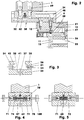
- FIGS. 1 and 2 show a parallel gripper device with two each on slide (15) seated jaws (1, 2).
- the carriages (15), which are movable in their longitudinal direction, are guided, for example, in a sliding manner in a base body (11) in a guide groove (12).
- the guide body (12) receiving the base body (11) further surrounds an example double-acting cylinder-piston unit (25).
- the cylinder-piston unit acts on the carriages (15) via a double-spline wedge mechanism (20).
- an adjustable attachment adapter (30) is attached on each carriage (15) on each carriage (15) on each carriage (15) an adjustable attachment adapter (30) is attached. The latter carries the manually displaceable on it gripping elements (1, 2).
- the FIG. 2 represents the left half of the parallel gripping device in partial longitudinal section.
- the gripping jaw (1) is in the open position.
- the substantially cuboid base body (11) of the parallel gripper device consists of an upper guide section and a lower drive section.
- the length of the base body (11) is for example almost twice as long as its width and the body height.
- the guide section centrally accommodates the guide groove (12) which is open towards the top - towards the gripping elements (1, 2) and which, for example, has a rectangular cross section. In the side walls of the guide groove (12), for example, separate guide rails are incorporated.
- the drive section located below the guide section essentially accommodates the cylinder-piston unit (25).
- an oval cylindrical recess (13) projects into the base body (11) in the direction of the guide groove (12), cf. FIG. 2 .
- a through hole which connects the cylinder recess (13) with the guide groove (12).
- the through hole has a recess for receiving a piston rod sealing ring.
- an oval piston (26) with its piston rod (27) is arranged in the cylinder recess (13), which is tightly closed by a cover.
- the piston rod (27) is screwed to the piston (26).
- the piston (26) and the double slide wedge (21) of the double slide wedge gear (20) together form a dimensionally stable assembly.
- the double slide wedge (21) is arranged in the guide groove (12) as part of a double slide wedge gear (20). He has at its front ends in each case a beveled wedge angle in the end face, which is in each case part of a T-shaped wedge web. Each of the two wedge webs of the double slip wedge (21) engages positively in a carriage (15) mounted in the guide groove (12).
- Each carriage (15) is primarily a cuboid body.
- a bevelled end face a Keilstegnut for receiving the respective wedge web of the double slide wedge (21) is provided.
- On both sides are e.g. each incorporated two Schlitten Adjustsnuten in the carriage. With these grooves, the single carriage (15) is slidably mounted on the guide rails.
- each carriage (15) On top of each carriage (15) is an e.g. cuboidal elevation which, when the carriage (15) is mounted at the top, can be increased by e.g. 1.2 mm - projecting beyond the top of the main body - protruding from the guide groove (12).
- the flat top of the elevation has two threaded bores equipped with cylinder countersinks to which the gripping jaws (1, 2) are releasably attached. Centering sleeves for precise, at least form-fitting positioning of the guide attachment (32) of the attachment adapter (30) on the carriage (15) are located in the cylinder counterbores.
- the slides (15) are here in the guide groove (12), see. FIG. 1, arranged one behind the other, so that their mutually facing end faces contact or at least almost touch each other with a minimal gripping jaw spacing.
- the middle region of the slot opening of the guide groove (12) is closed with a rectangular cover plate, for example.
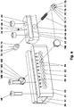
- the attachment adapter comprises two larger components, a carriage adapter (31) and a gripper element adapter (61) carried by it.
- the carriage adapter (31) is a guide attachment (32) in the form of a guide rail.
- a guide attachment 32) in the form of a guide rail.
- FIG. 3 which is for example 29 mm in the lower region and, for example, 20 mm in the upper, narrower region.
- the plate-like base part (33) on both sides of which the Greifelemeteadapter (61) partially encompassing side cheeks (34, 35) are integrally formed.
- the base part (33) with which the guide attachment (32) is fastened to the respective carriage (15) has in its two end regions in each case two fastening bores (37) arranged one behind the other along the longitudinal direction.
- the center lines of both holes (37) lie on the vertical central longitudinal plane (8) of the gripping device (10).
- the distance between the holes (37) is 24 mm.
- the outer bore (37) of the after FIG. 1 front hole group has the next component front side a distance of 9.1 mm, while the outer bore (37) of the after FIG. 1 rear hole group to the nearest end face of the guide attachment (32) is 13 mm. All four holes (37) are equipped on both sides to accommodate centering sleeves or screw heads with cylindrical countersinks.
- Both side cheeks (34, 35) have a row locking recess (51).
- the latter are mirror-symmetrical with respect to the vertical center longitudinal plane (8).
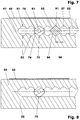
- the row-locking recess (51) is a superimposition of a displacement recess (52), in FIG FIG. 7 shown in dashed lines, and a plurality of in the same division (58) juxtaposed Einzelelsperrausappellus (53). According to the embodiment, there are 11 EinzelelsperrausNeill (53) with a pitch (58) of 7 mm.
- the row locking recess (51) has a center line (47) parallel to the carriage traversing direction (9), which lies, for example, halfway between the bottom (41) of the guide groove (36) and the wrap flank (42) of the side cheeks (34, 35), cf.
- a numbering is arranged above the row locking recess (51), which assigns a number to each individual locking recess (53).
- the sliding recess (52), which makes it possible to move the gripping element adapter (61) by means of the actuating elements (100) along the entire row locking recess (51), has e.g. a height of 4.6 mm.
- the Einzelperperrausoutlinedung (53) has in the plane of FIG. 7 the diamond-shaped cross-section (91) having a square surface.
- Each linear cross-sectional edge represents a plane blocking flank (55, 56).
- Two adjacent blocking flanks pass over a rounding (57), which for example has a 2.1 mm radius.
- the blocking flanks (55, 56) have a load-bearing length of 2.15 mm along the straight cross-sectional edge here.
- a tooth (99) of the row locking recess (51) is formed.
- the contour of the row locking recess (51) is chamfered along the inner side edges (38) of the guide groove (36).
- the four vertical edges of the guide attachment (32) are rounded here with a 5 mm radius.
- the sliding carriage (62) is essentially a cuboid, for example, 52 mm long and 27 mm wide body, which is mirror-symmetrical to the vertical center longitudinal plane (8). Its maximum height is 17.6 mm.
- T-slot sliding carriage (62) on both sides, for example, a 6.6 mm high Umgreifabsatz (63).
- the sliding carriage (62) has two fastening threaded bores (64) to the center line (7).
- the fastening threaded holes (64) have cylindrical countersinks on both sides and a distance of eg 24 mm.
- the gripping elements (1, 2) on the sliding carriage (62) with the interposition of centering sleeves by means of screws (49) attached.
- a stepped bore (65) which is after FIGS. 2, 4 and 5 in the lower part, for example, has an M3 thread.
- the upper area has a diameter of 3 or 4 mm.
- a finely machined guide bore (66) which is oriented perpendicular to the center line (7) and perpendicular to the gripping direction (9).
- the guide bore (66) opens the stepped bore (65).
- a threaded pin (67) is screwed, the pin (68), for example, 0.8 mm in the guide bore (66) projects as a stop.
- the set screw (67) in its rear, the pin (68) facing away from a widening over which it rests as a depth stop on a - located between the upper and the lower stepped bore portion of the stepped bore (65) - Federal.
- the four vertical edges of the guide attachment (32) are e.g. rounded with a 4 mm radius.
- the single, one-piece blocker (71, 72) consists of a cylindrical sliding piece (73) and a locking piece (75).
- the sliding piece (73) slidably fitted in the guide bore (66) with a small clearance has, for example, a length of 7.3 mm at a diameter of 8.87 mm. It has a flat face, in which a 7 mm deep blind hole hole is incorporated. The latter is used with an inner diameter of 5 mm as a spring guide bore (74).
- the molded on the sliding piece (73), e.g. 6 mm long locking piece (75) is a square, whose theoretical edge lengths measure 7.5 mm.
- the longitudinal edges of the square are e.g. rounded off with a 2.1 mm radius.
- the end face is provided around it with a 0.5 * 30 ° Rast Koreanfrontfase (77), which guarantees easy insertion into a Einzelsperraus Principleung (53).
- In the center of the end face is a e.g. 3 mm deep M3 threaded hole (78), in which the actuator (100) can be accommodated.
- a helical compression spring (87) is arranged, which is supported on the two bottoms of the spring guide bores (74).
- a flat stop collar (79) which consists of four circular sections here.
- the detachable one-piece actuators (100) are e.g. Rotary parts, consisting of an actuator (101), an operating shaft (102) and an M3 external thread.
- the disc-shaped actuator (101) has e.g. with a width of 5 mm an ergonomically favorable diameter of 13 mm.
- the e.g. 9.5 mm long cylindrical shaft (102) has a diameter of 3 mm.
- the actuating elements (100) are screwed into the actuating threaded bores (78) of the blocking devices (71, 72).
- the respective catcher (71, 72) does not rotate in the guide bore (66) of the sliding carriage (62).
- both locking pieces (75) are completely unlocked from the individual locking recesses (53) which have been stored so far.
- the inner end faces of the blocker (71, 72) come here on the pin (68) of the threaded pin (67) to the plant.
- the actuating elements (100) are released. Under the pressure of the locking spring (87) the locking pieces (75) are inserted into the new Einzelsperraus Principleung (53). Thereafter, the sliding carriage (62) is locked in the guide attachment (32). Finally, the actuators (100) from the blockers (71, 72) are unscrewed.
Abstract
Die Erfindung betrifft einen einstellbaren Aufsatzadapter zum manuellen Verschieben eines auf einem Schlitten (15) einer Greifvorrichtung (10) gelagerten Greifelements (1, 2), wobei an dem Schlitten ein Schlittenadapter (31) und an dem Greifelement (1, 2) ein Greifelementeadapter (61) befestigt ist. Dabei ist an dem Schlitten ein Schlittenadapter (31) und an dem Greifelement (1, 2) ein Greifelementeadapter (61) befestigt. Zwischen dem Schlittenadapter (31) und dem Greifelementadapter (61) ist mindestens ein formschlüssiges, durch eine lineare manuelle Schiebebewegung gegen eine Federkraft entrastbares Riegel- oder Zahnrichtgesperre (70) angeordnet.The invention relates to an adjustable attachment adapter for manually displacing a gripping element (1, 2) mounted on a carriage (15) of a gripping device (10), wherein a carriage adapter (31) is mounted on the carriage and a gripping element adapter (1, 2) on the carriage. 61) is attached. In this case, a carriage adapter (31) is attached to the carriage and a gripper element adapter (61) is fastened to the gripper element (1, 2). Between the carriage adapter (31) and the gripping element adapter (61) is at least one positive, by a linear manual sliding movement unlockable against a spring force latch or Zahnrichtgesperre (70) is arranged.
Mit der vorliegenden Erfindung wird ein einstellbarer Aufsatzadapter in Verbindung mit einer Greifvorrichtung (10) für große Klemmkräfte entwickelt, dessen Greif- bzw. Zangenweite auf einfache Weise verstellbar ist.

Description
Die Erfindung betrifft einen einstellbaren Aufsatzadapter zum manuellen Verschieben eines auf einem Schlitten einer Greifvorrichtung gelagerten Greifelements, wobei an dem Schlitten ein Schlittenadapter und an dem Greifelement ein Greifelementeadapter befestigt ist.The invention relates to an adjustable attachment adapter for manually displacing a gripping element mounted on a carriage of a gripping device, wherein a carriage adapter is attached to the carriage and a gripping element adapter is attached to the gripping element.
Aus der
Der vorliegenden Erfindung liegt die Problemstellung zugrunde, einen einstellbaren Aufsatzadapter in Verbindung mit einer Greifvorrichtung für große Klemmkräfte zu entwickeln, dessen Greif- bzw. Zangenweite auf einfache Weise verstellbar ist.The present invention is based on the problem to develop an adjustable attachment adapter in conjunction with a gripping device for large clamping forces whose gripping or forceps width is easily adjustable.
Diese Problemstellung wird zum einen mit den Merkmalen des Patentanspruchs 1 gelöst. Dabei ist an dem Schlitten ein Schlittenadapter und an dem Greifelement ein Greifelementeadapter befestigt. Zwischen dem Schlittenadapter und dem Greifelementeadapter ist mindestens ein formschlüssiges, durch eine lineare manuelle Schiebebewegung gegen eine Federkraft entrastbares Riegel- oder Zahnrichtgesperre angeordnet.This problem is solved on the one hand with the features of
Das Riegel- oder Zahnrichtgesperre hat einen Sperrer, der zur Änderung der Greif- bzw. Zangenweite der Greifvorrichtung mit einem Sperrstück zusammenwirkt, das in Einstellsverschieberichtung hintereinander mehrere gleichmäßig oder ungleichmäßig geteilte Riegel- oder Rastausnehmungen aufweist. Mit der oder den Aufsatzadaptern ist es möglich, den regulären Werkstückspannbereich einer Greifvorrichtung beispielsweise um das Mehrfache manuell zu vergrößern. Bei Greifvorrichtungen, die zum Greifen leichter Werkstücke ausgelegt sind, werden die größeren Bauteile der Aufsatzadapter aus einer Aluminiumlegierung gefertigt.The bar or Zahnrichtgesperre has a blocker, which cooperates to change the gripping or forceps width of the gripping device with a locking piece, which has in Einstellsverschieberichtung successively more evenly or non-uniformly divided locking or recesses. With the one or more attachment adapters, it is possible to manually increase the regular workpiece clamping range of a gripping device, for example by several times. In gripping devices that are designed to grip light workpieces, the larger components of the attachment adapters are made of an aluminum alloy.
Angetrieben werden die Schlitten beispielsweise über drei hintereinander angeordnete Getriebe, z.B. ein Stirnradgetriebe, ein Schneckengetriebe und ein Zahnstangengetriebe. Anstelle dieser Getriebe oder zusätzlich zu mindestens einem Teil dieser Getriebe können auch Schiebekeilgetriebe, Kurven-, Hebel-, Kulissen- oder Zugmittelgetriebe eingesetzt werden.The carriages are driven, for example, by means of three gears arranged in series, for example a spur gear, a worm gear and a rack gear. Instead of these transmissions or in addition to at least a portion of these transmissions, it is also possible to use sliding wedge gearing, curved, lever, slide or traction mechanism transmissions.
In den Ausführungsbeispielen werden nur Teile von Parallelgreifern gezeigt. Selbstverständlich können die meisten Teile, mit Ausnahme des Gehäuses, auch für Drei-, Vier- und Mehrbacken-, Mehrschlitten- oder Zentrischgreifer verwendet werden, so dass die dargestellte Problemlösung auch dort eingesetzt werden kann. Der Aufsatzadapter kann sowohl in Außen- als auch in Innengreifern verwendet werden.In the embodiments, only parts of parallel grippers are shown. Of course, most parts, with the exception of the housing, for three-, four- and multi-jaw, multi-slide or centric gripper can be used, so that the problem solution shown can also be used there. The attachment adapter can be used in both external and internal grippers.
Selbstverständlich ist die Lösung des Problems auf einen Winkelgreifer übertragbar. Dazu wird der im Grundkörper der Greifvorrichtung verschiebbar geführte Schlitten durch einen greifelementetragenden Schwenkarm ersetzt, der im Grundkörper in einem Schwenkgelenk schwenkbar gelagert ist. An dem Schwenkarm wird hier der Schlittenadapter befestigt.Of course, the solution of the problem is transferable to an angle gripper. For this purpose, the slidably guided in the main body of the gripping device carriage is replaced by a gripping element-carrying pivot arm which is pivotally mounted in the base body in a pivot joint. On the swivel arm of the carriage adapter is attached here.
Entgegen der Darstellung in dem Ausführungsbeispiel kann der Schlittenadapter ein relativ kurzer nutensteinartiger Körper sein, auf dem der Greifelementeadapter in Gestalt einer langen Führungsschiene verschiebbar sitzt.Contrary to the illustration in the embodiment, the carriage adapter may be a relatively short nut-like body on which the gripping element adapter is slidably seated in the form of a long guide rail.
Nach dem Ausführungsbeispielen weisen der Schittenadapter und der Greifelementeadapter jeweils zwei Rastsysteme auf, bei denen je ein Sperrer in je einer Seitenwange eines als Sperrstück dienenden Führungsaufsatzes in einer von mehreren Sperrausnehmungen verriegel- oder verrastbar ist. Es ist jedoch auch möglich, nur ein Rastsystem einzusetzen. Es kann dabei z.B. nur in einer Seitenwange oder auch im Boden des Führungsaufsatzes integriert oder angebaut sein.According to the embodiments, the Schittenadapter and the Greifelementeadapter each have two locking systems, in each of which a locker in each side cheek of serving as a locking piece guide attachment in one of a plurality of locking recesses is locked or latched. However, it is also possible to use only one locking system. It can be integrated or grown eg only in a side wall or in the bottom of the guide attachment.
Weitere Einzelheiten der Erfindung ergeben sich aus den Unteransprüchen und der nachfolgenden Beschreibung schematisch dargestellter Ausführungsformen.
- Figur 1:
- Perspektivische Ansicht einer Parallelgreifvorrichtung;
- Figur 2:
- halbseitiger Schnitt zu
Figur 1 - Figur 3:
- Querschnitt des Führungsaufsatzes;
- Figur 4:
- Querschnitt des Führungsaufsatzes und des Schiebeschlittens in verrasteter Position;
- Figur 5:
- wie
Figur 4 , jedoch in unverrasteter Position; - Figur 6:
- Explosionszeichnung des einstellbaren Aufsatzadapters;
- Figur 7:
- vergrößerter Längsschnitt durch den Führungsaufsatz;
- Figur 8:
- wie
Figur 7
- FIG. 1:
- Perspective view of a parallel gripper device;
- FIG. 2:
- half-sided cut too
FIG. 1 ; - FIG. 3:
- Cross section of the guide attachment;
- FIG. 4:
- Cross section of the guide attachment and the sliding carriage in the locked position;
- FIG. 5:
- as
FIG. 4 , but in an unlocked position; - FIG. 6:
- Exploded view of the adjustable attachment adapter;
- FIG. 7:
- enlarged longitudinal section through the guide attachment;
- FIG. 8:
- as
FIG. 7 but with only one row of teeth.
Die
Die
Der unterhalb des Führungsabschnittes gelegene Antriebsabschnitt nimmt im Wesentlichen die Zylinder-Kolben-Einheit (25) auf. Von der Grundkörperunterseite aus ragt eine z.B. ovale Zylinderausnehmung (13) in den Grundkörper (11) in Richtung der Führungsnut (12) hinein, vgl.
In der von einem Deckel dicht verschlossenen Zylinderausnehmung (13) ist ein ovaler Kolben (26) mit seiner Kolbenstange (27) angeordnet. Die Kolbenstange (27) ist am Kolben (26) angeschraubt. Der Kolben (26) und der Doppelschiebekeil (21) des Doppelschiebekeilgetriebes (20) bilden zusammen eine formsteife Baugruppe.In the cylinder recess (13), which is tightly closed by a cover, an oval piston (26) with its piston rod (27) is arranged. The piston rod (27) is screwed to the piston (26). The piston (26) and the double slide wedge (21) of the double slide wedge gear (20) together form a dimensionally stable assembly.
Der Doppelschiebekeil (21) ist in der Führungsnut (12) als Teil eines Doppelschiebekeilgetriebes (20) angeordnet. Er weist an seinen stirnseitigen Enden jeweils eine im Schiebekeilwinkel abgeschrägte Stirnfläche auf, die jeweils Teil eines T-förmigen Keilstegs ist. Jeder der beiden Keilstege des Doppelschiebekeils (21) greift formschlüssig in einen in der Führungsnut (12) gelagerten Schlitten (15) ein.The double slide wedge (21) is arranged in the guide groove (12) as part of a double slide wedge gear (20). He has at its front ends in each case a beveled wedge angle in the end face, which is in each case part of a T-shaped wedge web. Each of the two wedge webs of the double slip wedge (21) engages positively in a carriage (15) mounted in the guide groove (12).
Jeder Schlitten (15) ist primär ein quaderförmiger Körper. In je einer abgeschrägten Stirnseite ist eine Keilstegnut zur Aufnahme des jeweiligen Keilstegs des Doppelschiebekeils (21) vorgesehen. Beidseitig sind z.B. je zwei Schlittenführungsnuten in den Schlitten eingearbeitet. Mit diesen Nuten ist der einzelne Schlitten (15) auf den Führungsschienen gleitgelagert.Each carriage (15) is primarily a cuboid body. In each case a bevelled end face a Keilstegnut for receiving the respective wedge web of the double slide wedge (21) is provided. On both sides are e.g. each incorporated two Schlittenführungsnuten in the carriage. With these grooves, the single carriage (15) is slidably mounted on the guide rails.
Auf der Oberseite jedes Schlittens (15) befindet sich eine z.B. quaderförmige Erhöhung, die bei montiertem Schlitten (15) oben um z.B. 1,2 mm - über die Grundkörperoberseite überstehend - aus der Führungsnut (12) herausragt. Die ebene Oberseite der Erhöhung hat zwei mit Zylindersenkungen ausgestattete Gewindebohrungen, an denen die Greifbacken (1, 2) lösbar befestigt werden. In den Zylindersenkungen stecken Zentrierhülsen zur präzisen, zumindest formschlüssigen Positionierung des Führungsaufsatzes (32) des Aufsatzadapters (30) auf den Schlitten (15).On top of each carriage (15) is an e.g. cuboidal elevation which, when the carriage (15) is mounted at the top, can be increased by e.g. 1.2 mm - projecting beyond the top of the main body - protruding from the guide groove (12). The flat top of the elevation has two threaded bores equipped with cylinder countersinks to which the gripping jaws (1, 2) are releasably attached. Centering sleeves for precise, at least form-fitting positioning of the guide attachment (32) of the attachment adapter (30) on the carriage (15) are located in the cylinder counterbores.
Die Schlitten (15) sind hier in der Führungsnut (12), vgl. Figur 1, so hintereinander angeordnet, dass sich bei minimalem Greifbackenabstand ihre einander zugewandten Stirnseiten kontaktieren oder zumindest fast berühren. Der mittlere Bereich der Nutöffnung der Führungsnut (12) ist mit einer z.B. rechteckigen Abdeckplatte verschlossen.The slides (15) are here in the guide groove (12), see. FIG. 1, arranged one behind the other, so that their mutually facing end faces contact or at least almost touch each other with a minimal gripping jaw spacing. The middle region of the slot opening of the guide groove (12) is closed with a rectangular cover plate, for example.
Der Aufsatzadapter umfasst zwei größere Bauteile, einen Schlittenadapter (31) und einen von ihm getragenen Greifelementeadapter (61). In den Ausführungsbeispielen ist der Schlittenadapter (31) ein Führungsaufsatz (32) in Form einer Führungsschiene. Dazu hat er eine quaderförmige Gestalt, in der in Längsrichtung eine T-nutartige z.B. 11 mm hohe Führungsnut (36) eingearbeitet ist, vgl.
Das Basisteil (33), mit dem der Führungsaufsatz (32) am jeweiligen Schlitten (15) befestigt wird, hat in seinen beiden Endbereichen jeweils zwei entlang der Längsrichtung hintereinanderliegende Befestigungsbohrungen (37). Die Mittellinien beider Bohrungen (37) liegen auf der vertikalen Mittenlängsebene (8) der Greifvorrichtung (10). Der Abstand der Bohrungen (37) beträgt jeweils 24 mm. Die äußere Bohrung (37) der nach
Beide Seitenwangen (34, 35) weisen eine Reihensperrausnehmung (51) auf. Letztere liegen sich spiegelsymmetrisch zur vertikalen Mittenlängsebene (8) gegenüber. Die Reihensperrausnehmung (51) ist eine Überlagerung einer Verschiebeausnehmung (52), in
Die Verschiebeausnehmung (52), die es ermöglicht, den Greifelementeadapter (61) mittels der Betätigungselemente (100) entlang der gesamten Reihensperrausnehmung (51) zu verschieben, hat z.B. eine Höhe von 4,6 mm.The sliding recess (52), which makes it possible to move the gripping element adapter (61) by means of the actuating elements (100) along the entire row locking recess (51), has e.g. a height of 4.6 mm.
Die Einzelsperrausnehmung (53) hat in der Zeichnungsebene von
Durch zwei benachbarte Sperrflanken, die über die Wandung der Verschiebeausnehmung (52) miteinander verbunden sind, wird ein Zahn (99) der Reihensperrausnehmung (51) gebildet. Die Kontur der Reihensperrausnehmung (51) ist entlang der inneren Seitenflanken (38) der Führungsnut (36) angefast.By two adjacent locking flanks, which are connected to each other via the wall of the Verschiebeausnehmung (52), a tooth (99) of the row locking recess (51) is formed. The contour of the row locking recess (51) is chamfered along the inner side edges (38) of the guide groove (36).
Anstelle des quadratischen Querschnitts (91) kann auch ein rautenförmiger Querschnitt benutzt werden, wobei der eingeschlossene Winkel - zweier benachbarter durch die Ausrundung (57) getrennter Sperrflanken (55, 56) - zwischen 30 und 120 Winkelgraden liegen kann.Instead of the square cross-section (91) and a diamond-shaped cross section can be used, wherein the enclosed Angle - two adjacent by the fillet (57) separated locking edges (55, 56) - can be between 30 and 120 degrees.
Die vier vertikalen Kanten des Führungsaufsatzes (32) sind hier mit einem 5 mm-Radius abgerundet.The four vertical edges of the guide attachment (32) are rounded here with a 5 mm radius.
Der Schiebeschlitten (62) ist im Wesentlichen ein quaderförmiger z.B. 52 mm langer und 27 mm breiter Körper, der zur vertikalen Mittenlängsebene (8) spiegelsymmetrisch aufgebaut ist. Seine maximale Höhe beträgt 17,6 mm. Nach den
Nach
Unterhalb der Stufenbohrung (65) und zwischen den Befestigungsgewindebohrungen (64) befindet sich eine feinbearbeitete Führungsbohrung (66), die senkrecht zur Mittellinie (7) und senkrecht zur Greifrichtung (9) orientiert ist. In die Führungsbohrung (66) mündet die Stufenbohrung (65). In das Gewinde der Stufenbohrung (65) ist ein Gewindestift (67) eingeschraubt, dessen Zapfen (68) z.B. 0,8 mm in die Führungsbohrung (66) als Anschlag hineinragt. Ggf. hat der Gewindestift (67) in seinem hinteren, dem Zapfen (68) abgewandten Bereich eine Verbreiterung, über die er als Tiefenanschlag an einem - zwischen dem oberen und dem unteren Stufenbohrungsabschnitt der Stufenbohrung (65) gelegenen - Bund ansteht.Below the stepped bore (65) and between the fastening threaded bores (64) is a finely machined guide bore (66), which is oriented perpendicular to the center line (7) and perpendicular to the gripping direction (9). In the guide bore (66) opens the stepped bore (65). In the thread of the stepped bore (65) a threaded pin (67) is screwed, the pin (68), for example, 0.8 mm in the guide bore (66) projects as a stop. Possibly. has the set screw (67) in its rear, the pin (68) facing away from a widening over which it rests as a depth stop on a - located between the upper and the lower stepped bore portion of the stepped bore (65) - Federal.
Die vier vertikalen Kanten des Führungsaufsatzes (32) sind z.B. mit einem 4 mm-Radius abgerundet.The four vertical edges of the guide attachment (32) are e.g. rounded with a 4 mm radius.
In der Führungsbohrung (66) des Schiebeschlittens (62) sind zwei Sperrer (71, 72) spiegelsymmetrisch zur vertikalen Mittenlängsebene (8) verschiebbar angeordnet, vgl.
Das am Schiebestück (73) angeformte, z.B. 6 mm lange Raststück (75) ist ein Vierkant, dessen theoretischen Kantenlängen 7,5 mm messen. Die Längskanten des Vierkants sind z.B. mit einem 2,1 mm-Radius abgerundet. Die Stirnfläche ist ringsherum mit einer 0,5*30°-Raststückfrontfase (77) versehen, die ein problemloses Einschieben in eine Einzelsperrausnehmung (53) garantiert. Im Zentrum der Stirnfläche befindet sich eine z.B. 3 mm tiefe M3-Gewindebohrung (78), in der das Betätigungselement (100) aufgenommen werden kann.The molded on the sliding piece (73), e.g. 6 mm long locking piece (75) is a square, whose theoretical edge lengths measure 7.5 mm. The longitudinal edges of the square are e.g. rounded off with a 2.1 mm radius. The end face is provided around it with a 0.5 * 30 ° Raststückfrontfase (77), which guarantees easy insertion into a Einzelsperrausnehmung (53). In the center of the end face is a e.g. 3 mm deep M3 threaded hole (78), in which the actuator (100) can be accommodated.
Zwischen beiden im Schiebeschlitten (62) eingebauten Sperrern (71, 72) ist eine Schraubendruckfeder (87) angeordnet, die sich an den beiden Böden der Federführungsbohrungen (74) abstützt. Zwischen dem Schiebestücke (73) und dem angeformten Raststück (75) befindet sich parallel zu den Stirnflächen des Sperrers (71, 72) ein planer Anschlagbund (79), der hier aus vier Kreisabschnitten besteht. Die Anschlagbünde (79) kontaktieren, nach
Die lösbaren, einteiligen Betätigungselemente (100) sind z.B. Drehteile, die aus einem Betätigungsteller (101), einem Betätigungsschaft (102) und einem M3-Außengewinde bestehen. Der scheibenförmige Betätigungsteller (101) hat z.B. bei einer Breite von 5 mm einen ergonomisch günstigen Durchmesser von 13 mm. Der z.B. 9,5 mm lange zylindrische Schaft (102) hat einen Durchmesser von 3 mm.The detachable one-piece actuators (100) are e.g. Rotary parts, consisting of an actuator (101), an operating shaft (102) and an M3 external thread. The disc-shaped actuator (101) has e.g. with a width of 5 mm an ergonomically favorable diameter of 13 mm. The e.g. 9.5 mm long cylindrical shaft (102) has a diameter of 3 mm.
Vor dem manuellen Verschieben der Greifelemente (1, 2) werden in die Betätigungsgewindebohrungen (78) der Sperrer (71, 72) die Betätigungselemente (100) eingeschraubt. Durch das Vierkantprofil des jeweiligen Raststücks (75) verdreht sich der jeweilige Sperrer (71, 72) nicht in der Führungsbohrung (66) des Schiebeschlittens (62). Durch das Zusammenschieben der Sperrer (71, 72) über die Betätigungselemente (100) in Richtung des Rasthubs (89), werden beide Raststücke (75) vollständig aus den sie bisher lagernden Einzelsperrausnehmungen (53) entriegelt. Die inneren Stirnflächen der Sperrer (71, 72) kommen hierbei am Zapfen (68) des Gewindestifts (67) zur Anlage.Before the manual displacement of the gripping elements (1, 2), the actuating elements (100) are screwed into the actuating threaded bores (78) of the blocking devices (71, 72). By the square profile of the respective locking piece (75), the respective catcher (71, 72) does not rotate in the guide bore (66) of the sliding carriage (62). By pushing together the blocking elements (71, 72) via the actuating elements (100) in the direction of the locking stroke (89), both locking pieces (75) are completely unlocked from the individual locking recesses (53) which have been stored so far. The inner end faces of the blocker (71, 72) come here on the pin (68) of the threaded pin (67) to the plant.
Nach dem Verschieben des Schiebeschlittens (62) in eine neue Verriegelungsposition werden die Betätigungselemente (100) losgelassen. Unter dem Druck der Sperrfeder (87) werden die Raststücke (75) in die neue Einzelsperrausnehmung (53) eingeschoben. Hiernach ist der Schiebeschlitten (62) im Führungsaufsatz (32) verriegelt. Abschließend werden die Betätigungselemente (100) aus den Sperrern (71, 72) herausgeschraubt.After moving the sliding carriage (62) to a new locking position, the actuating elements (100) are released. Under the pressure of the locking spring (87) the locking pieces (75) are inserted into the new Einzelsperrausnehmung (53). Thereafter, the sliding carriage (62) is locked in the guide attachment (32). Finally, the actuators (100) from the blockers (71, 72) are unscrewed.
Beim Greifen eines Werkstückes durch die Greifvorrichtung (10) legt sich in jeder Seitenwange (34, 35) des Führungsaufsatzes (32) in der Reihensperrausnehmung (51) ein Sperrer (71, 72) über sein Raststück (75) an. Der Querschnitt (81) des Raststückes (75) liegt deckungsgleich auf dem Querschnitt (91) der jeweiligen Einzelsperrausnehmung (53). Die Abstützflanken (76) des Raststückes (75) liegen in Belastungsrichtung pro Seitenwange (34, 35) an den beiden - durch die Verschiebeausnehmung (52) getrennten - großflächigen Sperrflanken (55, 56) an. Die beiden Sperrflanken (55, 56) keilen dabei das Raststück (75) zentrierend ein.When gripping a workpiece by the gripping device (10) puts in each side cheek (34, 35) of the guide attachment (32) in the Reihensperrausnehmung (51) a lock (71, 72) on its locking piece (75). The cross section (81) of the locking piece (75) lies congruently on the cross section (91) of the respective Einzelsperrausnehmung (53). The Abstützflanken (76) of the locking piece (75) lie in the loading direction per side cheek (34, 35) on the two - by Verschiebeausnehmung (52) separated - large locking edges (55, 56). The two locking edges (55, 56) thereby wedging the locking piece (75) centering.
Nach
- 1, 21, 2
- Greifelemente, GreifbackenGripping elements, gripping jaws
- 66
- Zentrierhülsen für (11) und (61)Centering sleeves for (11) and (61)
- 77
- Mittellinie für (10) und (25)Center line for (10) and (25)
- 88th
- vertikale Mittenlängsebenevertical middle longitudinal plane
- 99
- Greifrichtung, SchlittenverfahrrichtungGrab direction, carriage travel direction
- 1010
- Greifvorrichtung, ParallelgreifvorrichtungGripping device, parallel gripper device
- 1111
- Grundkörper, GehäuseBasic body, housing
- 1212
- Führungsnutguide
- 1313
- Zylinderausnehmungcylinder recess
- 1515
- Schlittencarriage
- 2020
- Doppelschiebekeilgetriebe, KeilhakengetriebeDouble slide key transmission, wedge hook transmission
- 2121
- DoppelschiebekeilDouble spline
- 2525
- Zylinder-Kolben-EinheitCylinder-piston unit
- 2626
- Kolbenpiston
- 2727
- Kolbenstangepiston rod
- 3030
- Aufsatzadaptertower adapter
- 3131
- Schlittenadapterplate adapter
- 3232
- Führungsaufsatz, Führungsschiene, Sperrstück Schiene, u-förmigGuide attachment, guide rail, locking piece rail, U-shaped
- 3333
- Basisteilbase
- 3434
- Seitenwange, erste, SperrstückSidewall, first, locking piece
- 3535
- Seitenwange, zweite, SperrstückSidewall, second, locking piece
- 3636
- Führungsnutguide
- 3737
- Befestigungsbohrungen mit je zwei SenkungenMounting holes with two countersinks each
- 3838
- Seitenflanken von (36)Side flanks of (36)
- 4141
- Boden von (36)Bottom of (36)
- 4242
- UmgriffsflankeUmgriffsflanke
- 4747
- Mittelliniecenter line
- 4848
- Schrauben, (32) an (12)Screws, (32) to (12)
- 4949
- Schrauben, (1) an (32)Screws, (1) to (32)
- 5151
- Reihensperrausnehmung zu (70)Row locking recess to (70)
- 5252
- VerschiebeausnehmungVerschiebeausnehmung
- 5353
- Einzelsperrausnehmung zu (70)Single locking recess to (70)
- 5454
- EinzelsperrausnehmungsfaseEinzelsperrausnehmungsfase
- 5555
- Sperrflanke, obenBlocking edge, top
- 5656
- Sperrflanke, untenBlocking edge, below
- 5757
- Ausrundungrounding
- 5858
- Teilung von (53)Division of (53)
- 5959
- Nummerierungnumbering
- 6161
- GreifelementeadapterGripping elements Adapter
- 6262
- Schiebeschlitten, T-nutensteinartiger KörperSliding carriage, T-slot stone body
- 6363
- UmgreifabsatzUmgreifabsatz
- 6464
- Befestigungsgewindebohrungen mit SenkungenFixing threaded holes with countersinks
- 6565
- Stufenbohrung mit Gewinde, vertikalStepped bore with thread, vertical
- 6666
- Führungsbohrung, QuerbohrungGuide bore, cross bore
- 6767
- Gewindestift mit Zapfen, AnschlagstiftThreaded pin with pin, stop pin
- 6868
- Zapfenspigot
- 6969
- Verschieberichtung von Rast- zu RastpositionDisplacement direction from detent to detent position
- 7070
- Riegel- oder ZahnrichtgesperreBar or Zahnrichtgesperre
- 7171
- Sperrer, ersterBlocker, first
- 7272
- Sperrer, zweiterBlocker, second
- 7373
- Schiebestücksliding piece
- 7474
- Federführungsbohrung, SacklochbohrungSpring guide hole, blind hole
- 7575
- Raststück, VierkantprofilLocking piece, square profile
- 7676
- Abstützflankensupport flanks
- 7777
- RaststückfrontfaseRaststückfrontfase
- 7878
- Betätigungsgewindebohrung, AusnehmungActuating threaded hole, recess
- 7979
- Anschlagbund zwischen (73) und (75)Stop collar between (73) and (75)
- 8181
- Querschnitt, quadratisch; von (75)Cross section, square; from (75)
- 8787
- Schraubendruckfeder, SperrfederHelical compression spring, locking spring
- 8989
- RasthubRasthub
- 9191
- Querschnitt, quadratisch; von (53)Cross section, square; from (53)
- 9999
- Zähneteeth
- 100100
- Betätigungselementjig
- 101101
- Betätigungstelleractuating plate
- 102102
- Betätigungsschaftactuating shaft
- 103103
- Gewindethread
Claims (9)
Applications Claiming Priority (1)
| Application Number | Priority Date | Filing Date | Title |
|---|---|---|---|
| DE102016011975.6A DE102016011975B4 (en) | 2016-10-10 | 2016-10-10 | Adjustable attachment adapter |
Publications (3)
| Publication Number | Publication Date |
|---|---|
| EP3305479A2 true EP3305479A2 (en) | 2018-04-11 |
| EP3305479A3 EP3305479A3 (en) | 2018-04-25 |
| EP3305479B1 EP3305479B1 (en) | 2021-03-31 |
Family
ID=60119764
Family Applications (1)
| Application Number | Title | Priority Date | Filing Date |
|---|---|---|---|
| EP17001663.8A Active EP3305479B1 (en) | 2016-10-10 | 2017-10-10 | Adjustable attachment adapter |
Country Status (2)
| Country | Link |
|---|---|
| EP (1) | EP3305479B1 (en) |
| DE (1) | DE102016011975B4 (en) |
Cited By (5)
| Publication number | Priority date | Publication date | Assignee | Title |
|---|---|---|---|---|
| CN108788291A (en) * | 2018-06-25 | 2018-11-13 | 上海杨岐视觉机器人有限公司 | A kind of chute-type robot hand of shear |
| CN108788290A (en) * | 2018-06-25 | 2018-11-13 | 上海杨岐视觉机器人有限公司 | A kind of centering type robot hand of shear |
| CN110722555A (en) * | 2019-10-15 | 2020-01-24 | 深圳市佳士机器人科技有限公司 | Industrial robot |
| CN114248292A (en) * | 2020-09-21 | 2022-03-29 | 上银科技股份有限公司 | Clamping jaw device |
| US11850734B2 (en) | 2020-09-09 | 2023-12-26 | Hiwin Technologies Corp. | Gripper device |
Families Citing this family (1)
| Publication number | Priority date | Publication date | Assignee | Title |
|---|---|---|---|---|
| DE102021212311A1 (en) | 2021-11-02 | 2023-05-04 | Festo Se & Co. Kg | Gripping system and method for operating a gripping system attached to an industrial robot |
Family Cites Families (9)
| Publication number | Priority date | Publication date | Assignee | Title |
|---|---|---|---|---|
| DD252343B1 (en) | 1986-09-01 | 1989-06-07 | Werkzeugmasch Okt Veb | DEVICE FOR AUTOMATIC SWITCHING OF GRIPPERS |
| DE8706525U1 (en) * | 1987-05-07 | 1987-07-02 | Preh, Industrieausruestungen Gmbh, 8740 Bad Neustadt, De | |
| US5924684A (en) | 1997-10-21 | 1999-07-20 | Cheng; Wen-He | Worktable |
| DE102004054177B3 (en) | 2004-11-10 | 2006-04-27 | Schunk Gmbh & Co. Kg Fabrik Für Spann- Und Greifwerkzeuge | Clamping or gripping device, in particular linear or centric gripper |
| JP5397833B2 (en) * | 2009-04-17 | 2014-01-22 | 株式会社Ihi | Long stroke robot hand |
| JP2011156649A (en) | 2010-02-04 | 2011-08-18 | Yaskawa Electric Corp | Gripper device and method for changing stroke amount thereof |
| DE102010020653B4 (en) | 2010-05-06 | 2015-02-12 | Schunk Gmbh & Co. Kg Spann- Und Greiftechnik | Slide lock and gripping device with slide lock |
| DE102013019034B4 (en) * | 2013-11-15 | 2019-05-09 | Günther Zimmer | Gripping device with separate guide rails |
| DE102013020490B4 (en) | 2013-12-11 | 2018-10-11 | Günther Zimmer | Drive device for a gripping device |
-
2016
- 2016-10-10 DE DE102016011975.6A patent/DE102016011975B4/en active Active
-
2017
- 2017-10-10 EP EP17001663.8A patent/EP3305479B1/en active Active
Cited By (6)
| Publication number | Priority date | Publication date | Assignee | Title |
|---|---|---|---|---|
| CN108788291A (en) * | 2018-06-25 | 2018-11-13 | 上海杨岐视觉机器人有限公司 | A kind of chute-type robot hand of shear |
| CN108788290A (en) * | 2018-06-25 | 2018-11-13 | 上海杨岐视觉机器人有限公司 | A kind of centering type robot hand of shear |
| CN110722555A (en) * | 2019-10-15 | 2020-01-24 | 深圳市佳士机器人科技有限公司 | Industrial robot |
| US11850734B2 (en) | 2020-09-09 | 2023-12-26 | Hiwin Technologies Corp. | Gripper device |
| CN114248292A (en) * | 2020-09-21 | 2022-03-29 | 上银科技股份有限公司 | Clamping jaw device |
| CN114248292B (en) * | 2020-09-21 | 2024-03-22 | 上银科技股份有限公司 | Clamping jaw device |
Also Published As
| Publication number | Publication date |
|---|---|
| EP3305479B1 (en) | 2021-03-31 |
| DE102016011975B4 (en) | 2024-02-22 |
| DE102016011975A1 (en) | 2018-04-12 |
| EP3305479A3 (en) | 2018-04-25 |
Similar Documents
| Publication | Publication Date | Title |
|---|---|---|
| EP3305479B1 (en) | Adjustable attachment adapter | |
| EP1263554B1 (en) | Parallel gripper | |
| EP0595074A1 (en) | Clamping device | |
| DE1946651C3 (en) | Tensioner for endless traction devices, especially for chains | |
| DE3136440A1 (en) | Clamping device for clamping tools | |
| EP3305480B1 (en) | Quick tightening adapter with an interface for gripping elements | |
| DE889106C (en) | Adjustable reamer or boring bar | |
| EP3563990B1 (en) | Gripping device with optimized double push wedge member ii | |
| EP2998068B1 (en) | Center tensioner with fast change jaws | |
| EP0195184B1 (en) | Jaw-changing device | |
| EP3563989B1 (en) | Gripping device with carriage optimised for lubrication | |
| EP3563973B1 (en) | Forceps | |
| EP1245346A1 (en) | Fluid actuated parallel grippper with two actuating units | |
| DE3732695C1 (en) | Hand tool | |
| DE10302255A1 (en) | Multiple fixture | |
| EP0837253B1 (en) | Connecting arrangement for profiles | |
| DE1750244A1 (en) | Device for setting a game between two bodies | |
| DE202010001548U1 (en) | Spindle nut gearbox and linear unit with such a gearbox | |
| DE19955289C2 (en) | Jack puller | |
| DE4229221C2 (en) | Pliers with adjustable jaw width | |
| DE3943134A1 (en) | CLAMPING DEVICE FOR A SLIDING PART ON A GUIDE | |
| EP1602446A2 (en) | Clamping device | |
| DE3136472C2 (en) | ||
| DE102008045975A1 (en) | Clamping device for secure storing and fixing of workpiece on work table, has jack column and tensioning arm, where spindle body with threaded guide is arranged for guiding pressure spindle | |
| DE202004008799U1 (en) | Clamping device, esp. machine jaw vice has adjustable jaw coupled to adjusting drive via toothed rack |
Legal Events
| Date | Code | Title | Description |
|---|---|---|---|
| PUAI | Public reference made under article 153(3) epc to a published international application that has entered the european phase |
Free format text: ORIGINAL CODE: 0009012 |
|
| STAA | Information on the status of an ep patent application or granted ep patent |
Free format text: STATUS: THE APPLICATION HAS BEEN PUBLISHED |
|
| PUAL | Search report despatched |
Free format text: ORIGINAL CODE: 0009013 |
|
| AK | Designated contracting states |
Kind code of ref document: A2 Designated state(s): AL AT BE BG CH CY CZ DE DK EE ES FI FR GB GR HR HU IE IS IT LI LT LU LV MC MK MT NL NO PL PT RO RS SE SI SK SM TR |
|
| AX | Request for extension of the european patent |
Extension state: BA ME |
|
| AK | Designated contracting states |
Kind code of ref document: A3 Designated state(s): AL AT BE BG CH CY CZ DE DK EE ES FI FR GB GR HR HU IE IS IT LI LT LU LV MC MK MT NL NO PL PT RO RS SE SI SK SM TR |
|
| AX | Request for extension of the european patent |
Extension state: BA ME |
|
| RIC1 | Information provided on ipc code assigned before grant |
Ipc: B25J 15/02 20060101AFI20180316BHEP |
|
| STAA | Information on the status of an ep patent application or granted ep patent |
Free format text: STATUS: REQUEST FOR EXAMINATION WAS MADE |
|
| 17P | Request for examination filed |
Effective date: 20181010 |
|
| RBV | Designated contracting states (corrected) |
Designated state(s): AL AT BE BG CH CY CZ DE DK EE ES FI FR GB GR HR HU IE IS IT LI LT LU LV MC MK MT NL NO PL PT RO RS SE SI SK SM TR |
|
| GRAP | Despatch of communication of intention to grant a patent |
Free format text: ORIGINAL CODE: EPIDOSNIGR1 |
|
| STAA | Information on the status of an ep patent application or granted ep patent |
Free format text: STATUS: GRANT OF PATENT IS INTENDED |
|
| INTG | Intention to grant announced |
Effective date: 20201102 |
|
| GRAS | Grant fee paid |
Free format text: ORIGINAL CODE: EPIDOSNIGR3 |
|
| GRAA | (expected) grant |
Free format text: ORIGINAL CODE: 0009210 |
|
| STAA | Information on the status of an ep patent application or granted ep patent |
Free format text: STATUS: THE PATENT HAS BEEN GRANTED |
|
| AK | Designated contracting states |
Kind code of ref document: B1 Designated state(s): AL AT BE BG CH CY CZ DE DK EE ES FI FR GB GR HR HU IE IS IT LI LT LU LV MC MK MT NL NO PL PT RO RS SE SI SK SM TR |
|
| REG | Reference to a national code |
Ref country code: GB Ref legal event code: FG4D Free format text: NOT ENGLISH Ref country code: CH Ref legal event code: EP |
|
| REG | Reference to a national code |
Ref country code: DE Ref legal event code: R096 Ref document number: 502017009853 Country of ref document: DE Ref country code: AT Ref legal event code: REF Ref document number: 1376421 Country of ref document: AT Kind code of ref document: T Effective date: 20210415 |
|
| REG | Reference to a national code |
Ref country code: IE Ref legal event code: FG4D Free format text: LANGUAGE OF EP DOCUMENT: GERMAN |
|
| REG | Reference to a national code |
Ref country code: LT Ref legal event code: MG9D |
|
| PG25 | Lapsed in a contracting state [announced via postgrant information from national office to epo] |
Ref country code: BG Free format text: LAPSE BECAUSE OF FAILURE TO SUBMIT A TRANSLATION OF THE DESCRIPTION OR TO PAY THE FEE WITHIN THE PRESCRIBED TIME-LIMIT Effective date: 20210630 Ref country code: HR Free format text: LAPSE BECAUSE OF FAILURE TO SUBMIT A TRANSLATION OF THE DESCRIPTION OR TO PAY THE FEE WITHIN THE PRESCRIBED TIME-LIMIT Effective date: 20210331 Ref country code: FI Free format text: LAPSE BECAUSE OF FAILURE TO SUBMIT A TRANSLATION OF THE DESCRIPTION OR TO PAY THE FEE WITHIN THE PRESCRIBED TIME-LIMIT Effective date: 20210331 Ref country code: NO Free format text: LAPSE BECAUSE OF FAILURE TO SUBMIT A TRANSLATION OF THE DESCRIPTION OR TO PAY THE FEE WITHIN THE PRESCRIBED TIME-LIMIT Effective date: 20210630 |
|
| PG25 | Lapsed in a contracting state [announced via postgrant information from national office to epo] |
Ref country code: RS Free format text: LAPSE BECAUSE OF FAILURE TO SUBMIT A TRANSLATION OF THE DESCRIPTION OR TO PAY THE FEE WITHIN THE PRESCRIBED TIME-LIMIT Effective date: 20210331 Ref country code: LV Free format text: LAPSE BECAUSE OF FAILURE TO SUBMIT A TRANSLATION OF THE DESCRIPTION OR TO PAY THE FEE WITHIN THE PRESCRIBED TIME-LIMIT Effective date: 20210331 Ref country code: SE Free format text: LAPSE BECAUSE OF FAILURE TO SUBMIT A TRANSLATION OF THE DESCRIPTION OR TO PAY THE FEE WITHIN THE PRESCRIBED TIME-LIMIT Effective date: 20210331 |
|
| REG | Reference to a national code |
Ref country code: NL Ref legal event code: MP Effective date: 20210331 |
|
| PG25 | Lapsed in a contracting state [announced via postgrant information from national office to epo] |
Ref country code: EE Free format text: LAPSE BECAUSE OF FAILURE TO SUBMIT A TRANSLATION OF THE DESCRIPTION OR TO PAY THE FEE WITHIN THE PRESCRIBED TIME-LIMIT Effective date: 20210331 Ref country code: CZ Free format text: LAPSE BECAUSE OF FAILURE TO SUBMIT A TRANSLATION OF THE DESCRIPTION OR TO PAY THE FEE WITHIN THE PRESCRIBED TIME-LIMIT Effective date: 20210331 Ref country code: LT Free format text: LAPSE BECAUSE OF FAILURE TO SUBMIT A TRANSLATION OF THE DESCRIPTION OR TO PAY THE FEE WITHIN THE PRESCRIBED TIME-LIMIT Effective date: 20210331 Ref country code: SM Free format text: LAPSE BECAUSE OF FAILURE TO SUBMIT A TRANSLATION OF THE DESCRIPTION OR TO PAY THE FEE WITHIN THE PRESCRIBED TIME-LIMIT Effective date: 20210331 Ref country code: NL Free format text: LAPSE BECAUSE OF FAILURE TO SUBMIT A TRANSLATION OF THE DESCRIPTION OR TO PAY THE FEE WITHIN THE PRESCRIBED TIME-LIMIT Effective date: 20210331 |
|
| PG25 | Lapsed in a contracting state [announced via postgrant information from national office to epo] |
Ref country code: PT Free format text: LAPSE BECAUSE OF FAILURE TO SUBMIT A TRANSLATION OF THE DESCRIPTION OR TO PAY THE FEE WITHIN THE PRESCRIBED TIME-LIMIT Effective date: 20210802 Ref country code: PL Free format text: LAPSE BECAUSE OF FAILURE TO SUBMIT A TRANSLATION OF THE DESCRIPTION OR TO PAY THE FEE WITHIN THE PRESCRIBED TIME-LIMIT Effective date: 20210331 Ref country code: RO Free format text: LAPSE BECAUSE OF FAILURE TO SUBMIT A TRANSLATION OF THE DESCRIPTION OR TO PAY THE FEE WITHIN THE PRESCRIBED TIME-LIMIT Effective date: 20210331 Ref country code: SK Free format text: LAPSE BECAUSE OF FAILURE TO SUBMIT A TRANSLATION OF THE DESCRIPTION OR TO PAY THE FEE WITHIN THE PRESCRIBED TIME-LIMIT Effective date: 20210331 Ref country code: IS Free format text: LAPSE BECAUSE OF FAILURE TO SUBMIT A TRANSLATION OF THE DESCRIPTION OR TO PAY THE FEE WITHIN THE PRESCRIBED TIME-LIMIT Effective date: 20210731 |
|
| REG | Reference to a national code |
Ref country code: DE Ref legal event code: R097 Ref document number: 502017009853 Country of ref document: DE |
|
| PG25 | Lapsed in a contracting state [announced via postgrant information from national office to epo] |
Ref country code: ES Free format text: LAPSE BECAUSE OF FAILURE TO SUBMIT A TRANSLATION OF THE DESCRIPTION OR TO PAY THE FEE WITHIN THE PRESCRIBED TIME-LIMIT Effective date: 20210331 Ref country code: DK Free format text: LAPSE BECAUSE OF FAILURE TO SUBMIT A TRANSLATION OF THE DESCRIPTION OR TO PAY THE FEE WITHIN THE PRESCRIBED TIME-LIMIT Effective date: 20210331 Ref country code: AL Free format text: LAPSE BECAUSE OF FAILURE TO SUBMIT A TRANSLATION OF THE DESCRIPTION OR TO PAY THE FEE WITHIN THE PRESCRIBED TIME-LIMIT Effective date: 20210331 |
|
| PLBE | No opposition filed within time limit |
Free format text: ORIGINAL CODE: 0009261 |
|
| STAA | Information on the status of an ep patent application or granted ep patent |
Free format text: STATUS: NO OPPOSITION FILED WITHIN TIME LIMIT |
|
| 26N | No opposition filed |
Effective date: 20220104 |
|
| REG | Reference to a national code |
Ref country code: CH Ref legal event code: PL |
|
| PG25 | Lapsed in a contracting state [announced via postgrant information from national office to epo] |
Ref country code: IS Free format text: LAPSE BECAUSE OF FAILURE TO SUBMIT A TRANSLATION OF THE DESCRIPTION OR TO PAY THE FEE WITHIN THE PRESCRIBED TIME-LIMIT Effective date: 20210731 |
|
| REG | Reference to a national code |
Ref country code: BE Ref legal event code: MM Effective date: 20211031 |
|
| PG25 | Lapsed in a contracting state [announced via postgrant information from national office to epo] |
Ref country code: MC Free format text: LAPSE BECAUSE OF FAILURE TO SUBMIT A TRANSLATION OF THE DESCRIPTION OR TO PAY THE FEE WITHIN THE PRESCRIBED TIME-LIMIT Effective date: 20210331 |
|
| PG25 | Lapsed in a contracting state [announced via postgrant information from national office to epo] |
Ref country code: LU Free format text: LAPSE BECAUSE OF NON-PAYMENT OF DUE FEES Effective date: 20211010 Ref country code: BE Free format text: LAPSE BECAUSE OF NON-PAYMENT OF DUE FEES Effective date: 20211031 |
|
| PG25 | Lapsed in a contracting state [announced via postgrant information from national office to epo] |
Ref country code: LI Free format text: LAPSE BECAUSE OF NON-PAYMENT OF DUE FEES Effective date: 20211031 Ref country code: CH Free format text: LAPSE BECAUSE OF NON-PAYMENT OF DUE FEES Effective date: 20211031 |
|
| PG25 | Lapsed in a contracting state [announced via postgrant information from national office to epo] |
Ref country code: IE Free format text: LAPSE BECAUSE OF NON-PAYMENT OF DUE FEES Effective date: 20211010 |
|
| PG25 | Lapsed in a contracting state [announced via postgrant information from national office to epo] |
Ref country code: HU Free format text: LAPSE BECAUSE OF FAILURE TO SUBMIT A TRANSLATION OF THE DESCRIPTION OR TO PAY THE FEE WITHIN THE PRESCRIBED TIME-LIMIT; INVALID AB INITIO Effective date: 20171010 |
|
| PG25 | Lapsed in a contracting state [announced via postgrant information from national office to epo] |
Ref country code: CY Free format text: LAPSE BECAUSE OF FAILURE TO SUBMIT A TRANSLATION OF THE DESCRIPTION OR TO PAY THE FEE WITHIN THE PRESCRIBED TIME-LIMIT Effective date: 20210331 |
|
| PG25 | Lapsed in a contracting state [announced via postgrant information from national office to epo] |
Ref country code: GR Free format text: LAPSE BECAUSE OF FAILURE TO SUBMIT A TRANSLATION OF THE DESCRIPTION OR TO PAY THE FEE WITHIN THE PRESCRIBED TIME-LIMIT Effective date: 20210331 |
|
| REG | Reference to a national code |
Ref country code: AT Ref legal event code: MM01 Ref document number: 1376421 Country of ref document: AT Kind code of ref document: T Effective date: 20221010 |
|
| PGFP | Annual fee paid to national office [announced via postgrant information from national office to epo] |
Ref country code: GB Payment date: 20231023 Year of fee payment: 7 |
|
| PG25 | Lapsed in a contracting state [announced via postgrant information from national office to epo] |
Ref country code: AT Free format text: LAPSE BECAUSE OF NON-PAYMENT OF DUE FEES Effective date: 20221010 |
|
| PGFP | Annual fee paid to national office [announced via postgrant information from national office to epo] |
Ref country code: IT Payment date: 20231030 Year of fee payment: 7 Ref country code: FR Payment date: 20231024 Year of fee payment: 7 Ref country code: DE Payment date: 20231101 Year of fee payment: 7 |