EP3304044B1 - System, vorrichtung und verfahren zur kontrolle von ausgegebenem klebematerial - Google Patents
System, vorrichtung und verfahren zur kontrolle von ausgegebenem klebematerial Download PDFInfo
- Publication number
- EP3304044B1 EP3304044B1 EP16800776.3A EP16800776A EP3304044B1 EP 3304044 B1 EP3304044 B1 EP 3304044B1 EP 16800776 A EP16800776 A EP 16800776A EP 3304044 B1 EP3304044 B1 EP 3304044B1
- Authority
- EP
- European Patent Office
- Prior art keywords
- adhesive
- processing device
- image
- camera
- boundary areas
- Prior art date
- Legal status (The legal status is an assumption and is not a legal conclusion. Google has not performed a legal analysis and makes no representation as to the accuracy of the status listed.)
- Active
Links
Images


Classifications
-
- G—PHYSICS
- G06—COMPUTING OR CALCULATING; COUNTING
- G06T—IMAGE DATA PROCESSING OR GENERATION, IN GENERAL
- G06T7/00—Image analysis
- G06T7/0002—Inspection of images, e.g. flaw detection
- G06T7/0004—Industrial image inspection
- G06T7/0006—Industrial image inspection using a design-rule based approach
-
- G—PHYSICS
- G01—MEASURING; TESTING
- G01N—INVESTIGATING OR ANALYSING MATERIALS BY DETERMINING THEIR CHEMICAL OR PHYSICAL PROPERTIES
- G01N21/00—Investigating or analysing materials by the use of optical means, i.e. using sub-millimetre waves, infrared, visible or ultraviolet light
-
- G—PHYSICS
- G01—MEASURING; TESTING
- G01N—INVESTIGATING OR ANALYSING MATERIALS BY DETERMINING THEIR CHEMICAL OR PHYSICAL PROPERTIES
- G01N21/00—Investigating or analysing materials by the use of optical means, i.e. using sub-millimetre waves, infrared, visible or ultraviolet light
- G01N21/62—Systems in which the material investigated is excited whereby it emits light or causes a change in wavelength of the incident light
- G01N21/63—Systems in which the material investigated is excited whereby it emits light or causes a change in wavelength of the incident light optically excited
- G01N21/64—Fluorescence; Phosphorescence
- G01N21/645—Specially adapted constructive features of fluorimeters
- G01N21/6456—Spatial resolved fluorescence measurements; Imaging
-
- G—PHYSICS
- G01—MEASURING; TESTING
- G01N—INVESTIGATING OR ANALYSING MATERIALS BY DETERMINING THEIR CHEMICAL OR PHYSICAL PROPERTIES
- G01N21/00—Investigating or analysing materials by the use of optical means, i.e. using sub-millimetre waves, infrared, visible or ultraviolet light
- G01N21/84—Systems specially adapted for particular applications
- G01N21/88—Investigating the presence of flaws or contamination
- G01N21/8851—Scan or image signal processing specially adapted therefor, e.g. for scan signal adjustment, for detecting different kinds of defects, for compensating for structures, markings, edges
-
- G—PHYSICS
- G06—COMPUTING OR CALCULATING; COUNTING
- G06F—ELECTRIC DIGITAL DATA PROCESSING
- G06F18/00—Pattern recognition
- G06F18/20—Analysing
- G06F18/22—Matching criteria, e.g. proximity measures
-
- G—PHYSICS
- G06—COMPUTING OR CALCULATING; COUNTING
- G06T—IMAGE DATA PROCESSING OR GENERATION, IN GENERAL
- G06T7/00—Image analysis
- G06T7/0002—Inspection of images, e.g. flaw detection
- G06T7/0004—Industrial image inspection
- G06T7/0008—Industrial image inspection checking presence/absence
-
- H—ELECTRICITY
- H04—ELECTRIC COMMUNICATION TECHNIQUE
- H04N—PICTORIAL COMMUNICATION, e.g. TELEVISION
- H04N23/00—Cameras or camera modules comprising electronic image sensors; Control thereof
- H04N23/56—Cameras or camera modules comprising electronic image sensors; Control thereof provided with illuminating means
-
- G—PHYSICS
- G01—MEASURING; TESTING
- G01N—INVESTIGATING OR ANALYSING MATERIALS BY DETERMINING THEIR CHEMICAL OR PHYSICAL PROPERTIES
- G01N21/00—Investigating or analysing materials by the use of optical means, i.e. using sub-millimetre waves, infrared, visible or ultraviolet light
- G01N21/62—Systems in which the material investigated is excited whereby it emits light or causes a change in wavelength of the incident light
- G01N21/63—Systems in which the material investigated is excited whereby it emits light or causes a change in wavelength of the incident light optically excited
- G01N21/64—Fluorescence; Phosphorescence
- G01N21/645—Specially adapted constructive features of fluorimeters
- G01N21/6456—Spatial resolved fluorescence measurements; Imaging
- G01N2021/646—Detecting fluorescent inhomogeneities at a position, e.g. for detecting defects
-
- G—PHYSICS
- G06—COMPUTING OR CALCULATING; COUNTING
- G06T—IMAGE DATA PROCESSING OR GENERATION, IN GENERAL
- G06T2207/00—Indexing scheme for image analysis or image enhancement
- G06T2207/10—Image acquisition modality
- G06T2207/10064—Fluorescence image
-
- G—PHYSICS
- G06—COMPUTING OR CALCULATING; COUNTING
- G06T—IMAGE DATA PROCESSING OR GENERATION, IN GENERAL
- G06T2207/00—Indexing scheme for image analysis or image enhancement
- G06T2207/10—Image acquisition modality
- G06T2207/10141—Special mode during image acquisition
-
- G—PHYSICS
- G06—COMPUTING OR CALCULATING; COUNTING
- G06T—IMAGE DATA PROCESSING OR GENERATION, IN GENERAL
- G06T2207/00—Indexing scheme for image analysis or image enhancement
- G06T2207/30—Subject of image; Context of image processing
- G06T2207/30108—Industrial image inspection
Definitions
- the present disclosure relates to material additives and inspection. More specifically, the present disclosure relates to adhesive processing and automated optical inspection (AOI) for manufactured products/devices.
- AOI automated optical inspection
- adhesively bonded interfaces for materials on a product visibly impact the cosmetics and perceived quality of a product. If excessive adhesive compounds are visible around edges or periphery of a device (e.g., integrated circuit, mechanical device, display, etc.) affixed to a product, this may not only affect the integrity of the adhesion, but further provide the impression to a user that the product is of inferior quality.
- EP1025968 B1 relates to a method and a device for checking the glue application on end faces of to be glued together workpieces of wood during the automated conveying operation of separated workpieces between a gluing station and a press for pressing together the to be glued together end surfaces of workpieces.
- US5030833A relates to an adhesive-application detection method and device for not only detecting the failure of adhesive application or the state of adhesive application, but also controlling the quantity of adhesive to be applied by the fluorescent emission in the adhesive application process in devices such as collators, box-making machines, book-binding machines or the like.
- a system for detecting defects in an adhesion area as defined by claim 1.
- a method for detecting defects in an adhesion area comprising as defined by claim 9.
- first, second, third, etc. may be used herein to describe various elements, components, regions, layers and/or sections, these elements, components, regions, layers and/or sections should not be limited by these terms. These terms may be only used to distinguish one element, component, region, layer or section from another element, component, region, layer or section. Terms such as “first,” “second,” and other numerical terms when used herein do not imply a sequence or order unless clearly indicated by the context. Thus, a first element, component, region, layer or section discussed below could be termed a second element, component, region, layer or section without departing from the teachings of the exemplary embodiments.
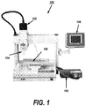
- an illustrative embodiment is shown of an adhesive dispenser 100, which, in this example, is a table adhesive dispenser. It should be understood by those skilled in the art that the particular configuration of dispenser 100 is shown for the purposes of illustrative purposes only, and is not intended to be limiting in any way. Any suitable dispenser, such as a single or plural station dispenser, and/or single- or plural-axis (e.g., 3-axis, 6-axis) dispenser may readily be used without departing from the scope of the present disclosure.
- Dispenser 100 of FIG. 1 comprises a display 108, which may comprise a computer that may be used to program dispenser 100.
- Dispensing pump 110 may be any suitable pump (e.g., time/pressure pump, auger pump, piston pump, etc.) for viscous fluids and may be coupled to nozzle 104 that may dispense adhesive material onto a device positioned on working surface 106 with the assistance of dispensing mechanism 102.
- Dispensing pump 110 may be coupled to an adhesive storage tank (not shown) that stores adhesive compounds for pump 110.
- Dispenser 100 may be configured to provide adhesives or other material for a wide variety of applications including, but not limited to, mechanical parts coating, cell phone buttons point glue, mobile phone battery packaging, laptop battery package, coil point glue, PCB bond fixed sealant, IC sealant, horn external punctuate glue, PDA sealant, LCD sealant, IC packaging, IC bonding, casing bonding, optical device processing, mechanical seal, and so forth.
- the applications may further include tongue-in-groove adhesion, lap shear, and joints under tensile, peel, or cleavage stress.
- matched colors may be used for adhesion.
- a black adhesive e.g., epoxy or polyurethane
- a clear adhesive may be used on a transparent polycarbonate or liquid crystal polymer.
- a device positioned on working surface 106 may be positioned using computer-assisted positioning technologies known in the art to ensure that adhesives and/or other material is being applied in a proper area.
- the device surface for receiving viscous material from nozzle 104 may be any suitable material, including polycarbonate (PC) material, glass-filled PC, liquid crystal polymer (LCP), glass-reinforced epoxy laminate (FR-4) sheets, tubes, rods and printed circuit boards (PCB), solder mask surfaces, aluminum, titanium, gold, copper, silicon, steel, stainless steel, etc.
- the viscous fluid (e.g., adhesive) dispensed from nozzle 104 may comprise epoxy adhesives, polyurethanes (PUR) and/or acrylics, silicones, hot melts, thermally or radiation-cured, etc. Additionally applicable fluid may comprise silica gel, EMI conductive adhesive, UV glue, AB glue, fast dry glue, sealant, grease, silver glue, red glue, solder paste, cooling paste, prevent solder paste, transparent lacquer, screw fixation agent, etc.
- the viscous material such as adhesive
- a fluorescing additive which would cause the material to fluoresce when illuminated with a light of a predetermined wavelength (e.g., UV light, IR light, etc.).
- the fluorescing additive may comprise less than 1% by weight of the adhesive-dye mixture in order to maintain the integrity of the adhesive. However, depending on the type of adhesive used and adhesive properties, greater amounts of fluorescing additive may be used as well.
- the specific fluorescing additive may vary depending on the application, and may be made from, contain, or be based one or more of a variety of dyes including, but not limited to, Acridine dyes, Cyanine dyes, Fluorone dyes, Oxazine dyes, Phenanthridine dyes, and Rhodamine dyes.
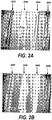
- FIGS. 2A and 2B provide illustrative examples some effects of adding fluorescent additives to adhesives.
- an epoxy is shown with four different fluorescent dye additives (202A, 204A, 206A, 208A), which have not been exposed to any specialized illumination.
- FIG. 2B shows the example of FIG. 2A exposed to UV light, where the additives (202B, 204B, 206B, 208B) fluoresces and can be seen visibly.
- the fluorescent additive may be advantageously used for Automated Optical Inspection (AOI) systems for use in defect detection.
- AOI Automated Optical Inspection
- FIG. 3 shows a simplified AOI system 300, wherein an object 302 is adhered to a work surface 306 using adhesive 304.
- the object may be any suitable object configured for adhesion including, but not limited to, a material, object, and/or circuit.
- adhesive 304 is an adhesive such as those described above comprising a fluorescing additive.
- the system 300 may further comprise a camera 312 coupled to a processing apparatus 314, such as a computer or workstation, where the camera 312 may be positioned to image the object 302, adhesive 304 and work surface 306 (collectively referred to herein as an "adhesion area") while one or more illuminating lights 308, 310 illuminate the adhesion area with a light comprising one or more predetermined wavelengths (e.g., UV, IR).
- a processing apparatus 314 such as a computer or workstation
- FIG. 3 shows two illuminating lights 308, 310, it should be understood that multiple lighting configurations are contemplated in the present disclosure. For example, a single light may be used in one embodiment. In another embodiment, three or more lights may be used depending on the fluorescent properties of the adhesive 304 and contrast between the object 302 and work surface 306. In another illustrative embodiment, one or more lights may be incorporated into the camera 312 and used for illumination. Additionally, a modulator 320 may be utilized in embodiments where one or more of the illuminating lights 308, 310 are modulated to affect the frequency or phase of illuminating light, described in greater detail below. The modulator 320 may be coupled directly to camera 312, which in turn creates an indirect connection to processing apparatus 314. Alternately, the modulator 320 may bypass the camera 312 and be directly connected to processing apparatus 314.
- Camera 312 may be embodied as a silicon-based camera, such as a charge-coupled (CCD) camera or active pixel sensors in complementary metal-oxide semiconductor (CMOS) or N-type metal-oxide semiconductor (NMOS, Live MOS) technologies.
- CCD charge-coupled
- CMOS complementary metal-oxide semiconductor
- NMOS N-type metal-oxide semiconductor
- Camera 312 may be configured as a dual-camera arrangement to accommodate stereo vision, which may increase accuracy.
- Camera 312 may further comprise one or more filters 316 and imaging circuitry 318, which may further include processors and other circuitry for processing images locally on camera 312.
- filters 316 may be embodied as fixed and/or removable optical filters that may pass and/or block predetermined wavelengths of light when camera 312 takes images of the adhesion area.
- camera 312 may be coupled to processing apparatus 314, such as a computer, which may be configured to provide control signals to control operation of camera 312, and process images received from camera 312.
- processing apparatus 314 may be a stand-alone device, or may further comprise communication circuitry to communicate over a network (e.g., WAN, LAN) in a wired or wireless manner.
- Processing apparatus 314 may further be equipped with software allowing it to apply filters, masks and/or boundaries to the images taken by camera 312, and may further allow processing apparatus 314 to detect characteristics of images received from camera 312 to detect potential defects in an adhesion area.
- a fluorescence signal i.e. the fluorescence signal to noise ratio
- the strength of a fluorescence signal is dependent upon a number of different parameters. For one, the amount of fluorescent dye present in the adhesive will determine the strength of the signal.
- Another way to increase the fluorescence signal to noise ratio is to increase the amount of light used to excite fluorescence.
- a third way to increase the fluorescence signal to noise ratio is to increase the sensitivity of the camera 312.
- camera 312 may be configured as a camera utilizing time-of-flight (TOF) imaging with or without the assistance of processing device 314.
- TOF imaging technology works by measuring the phase shift between emitted and detected infrared light at a high modulation frequency.
- the camera 312 may utilize lighting, such as LEDs or other suitable lighting, that emits light modulated at a higher frequency (e.g., 1-20 MHz), where this light then reflects off objects (e.g., fluoresced adhesive) in the adhesion area and is detected by the camera.
- a higher frequency e.g. 1-20 MHz
- the camera may use a combination of an infrared band-pass optical filter and a multi-bin (e.g., four-bin) lock-in detection scheme for each of the pixels to ensure that it is able to pick out what part of the total signal it receives is modulated at the given frequency (e.g., 1-20 MHz) and in the infrared.
- the phase shift between the emitted and detected signals is then used, in conjunction with the speed of light, to calculate the distance at which the reflection occurred for all pixels resulting in a distance image.
- these techniques may be replicated in other light wavebands as well.
- camera 312 may be configured to acquire fluorescence images by configuring the electric signal, to be sent to an LED of the proper power and fluorescence excitation wavelength light (e.g., 308, 310).
- a short pass filter e.g., ⁇ 800nm
- the camera 312 may be configured with a long-pass filer (e.g., >800nm), or other suitable filter, to ensure that the camera only sees the fluorescence signal.
- This configuration will allow for the fluorescence signal to be detected while suppressing the non-fluorescent background.
- An advantage of this camera configuration for fluorescence imaging is that the high modulation and detection frequency allows for all lower frequency noise, normally present in a fluorescence image, to be reduced or eliminated from the image. Pushing the desired fluorescent signal to a higher frequency (e.g., 1-20MHz) consequently minimizes the region for noise, thus increasing the sensitivity of camera 312 to the fluorescence signal.
- the optical power of the fluorescence signal can be three or four orders of magnitude smaller than the excitation signal. Thus being able to distinguish fluorescent photons from other, and often much brighter, sources of light may be important for acquiring a good fluorescence image.
- the fluorescence signal may be distinguished from other sources of light by utilizing lock-in detection which may be accomplished by modulating the fluorescence signal at one frequency and detecting only the signal that occurs at this frequency or frequency range.
- lock-in detection may be accomplished by modulating the fluorescence signal at one frequency and detecting only the signal that occurs at this frequency or frequency range.
- the amount of noise that can be eliminated with this technique may be dependent on the frequency of modulation. The less common the noise is at the frequency of modulation, the better the signal to noise ratio.
- processing apparatus 314 may utilize mask or boundary processing to process regions of interest of an adhesion area imaged by camera 312.
- FIG. 4 an illustrative embodiment is shown of a simulated image 400 captured by camera 312 of an object 402 affixed to a surface using adhesive 404 which has been mixed with a fluorescent dye and illuminated as described above.
- Processing apparatus 314 may partition the image 400 into one or more boundaries or regions 406-410, where the area in each boundary (e.g., 406-408, 408-410, 410-412) may be processed to determine one or more image characteristics, demonstrating the presence (or absence) of illuminated adhesive, which in turn may indicate a defect in the application of adhesive.
- an illustrative AOI method 500 is shown for processing fluoresced images under one embodiment.
- an AOI system e.g., system 300 positions an object for imaging. The positioning may be accomplished using manual techniques, automated techniques, or a combination of both as is known in the art. The positioning in block 502 is done so that camera 312 may accurately capture image areas of interest, such as an adhesion area.
- the system e.g., 300 loads or executes one or more masks and/or boundaries for the image to taken by camera 312 in block 506.
- processing apparatus 314 may perform image processing by analyzing a first peripheral boundary, defined by the edge of object 402 to first boundary 406 to determine the coverage of adhesion (e.g., image pixel coverage) in this area.
- the processing apparatus 314 may then move to the next boundary region defined by the outer periphery of boundary 408 and inner periphery of boundary 410 to determine the coverage of adhesion (e.g., image pixel coverage) in this area, and then to the next boundary region defined by the outer periphery of boundary 410 and inner periphery of boundary 412 to determine the coverage of adhesion in a similar manner.
- adhesion e.g., image pixel coverage
- certain boundary regions may be masked (e.g., 406-408, 408-410) while one or more regions are being processed (e.g., 410-412).
- This configuration may be advantageous in that the processing apparatus 314 may focus on specific areas of the adhesion area that may be susceptible to defects.
- the camera e.g., camera 312
- the masks and/or boundaries may be applied in block 508, as described above.
- boundaries may be set in increments of one or more centimeters, millimeters or micrometers. It should be understood by those skilled in the art that the order of loading and applying masks relative to the imaging in block 506 may be modified. For example, the loading and application of masks and/or boundaries may occur after the image is taken in an illustrative embodiment.
- the processing apparatus 314 processes the image to determine image characteristics using machine vision algorithms, and determines, using the image characteristics, if potential defects are present in block 512.
- processing apparatus 314 may simply calculate the coverage of illuminated pixels relative to an area in a boundary region, which would correspond to adhesive coverage in the area. Utilizing any of maximum and/or minimum thresholds, the processing apparatus 314 may determine if potential defects exist. For example, in a given adhesive application, it may be known that certain values should be present in a given boundary region. Thus, referring to the illustrative embodiment of FIG.
- processing apparatus 314 may determine from an image that an inner boundary area (e.g., between 406 and 408) has only 92% pixel coverage for the image boundary area, which would indicate only a 92% adhesive coverage. Since the adhesion application in this example is expected to have full coverage (i.e., 100%), since it is so close to the periphery of the object 402, having a lesser amount may indicate to processing apparatus that insufficient or defective adhesive is present.
- an inner boundary area e.g., between 406 and 408
- an intermediate or outer boundary region (e.g., between 408 and 410, or 410 and 412) may be processed to determine if adequate adhesive coverage is present.
- the adhesive coverage (or "spread") in the area may be non-uniform but expected to be a lesser amount (e.g., covering 50%) for the entire boundary area.
- Setting an appropriate threshold value or range e.g., 40-60%), the pixel coverage detection may be calculated by processing device 314 such that amounts greater and/or less than the threshold(s) indicates an excessive or insufficient adhesive coverage defect.
- the processing device 314 may be configured to detect defects on an absolute boundary threshold. For example, any detection of adhesive outside a boundary threshold automatically signals a defective adhesive application.
- processing device 314 may utilize edge detection techniques to analyze specific adhesive shapes, with or without the use of masks.
- Edge detection may comprise search-based or zero-crossing based techniques.
- a search-based approach detects edges by first computing a measure of edge strength, usually a first-order derivative expression such as the gradient magnitude, and then searches for local directional maxima of the gradient magnitude using a computed estimate of the local orientation of the edge, usually the gradient direction.
- the zero-crossing based approach searches for zero crossings in a second-order derivative expression computed from the image in order to find edges, usually the zero-crossings of the Laplacian or the zero-crossings of a non-linear differential expression.
- a smoothing stage such as Gaussian smoothing
- Other illustrative machine vision techniques include, but are not limited to, grayscale matching, gradient matching, and the like.
- fluorescing additives to adhesives provides an advantageous configuration for inspecting for defects, particularly in automated optical inspection systems utilizing machine learning algorithms. Utilizing TOF cameras also provides additional, accurate, image property detection while minimizing costs, as TOF cameras are readily available, inexpensive, and may be easily modified for automated optical inspection purposes.
Landscapes
- Engineering & Computer Science (AREA)
- Physics & Mathematics (AREA)
- General Physics & Mathematics (AREA)
- Health & Medical Sciences (AREA)
- Computer Vision & Pattern Recognition (AREA)
- Life Sciences & Earth Sciences (AREA)
- Biochemistry (AREA)
- Theoretical Computer Science (AREA)
- Pathology (AREA)
- Immunology (AREA)
- General Health & Medical Sciences (AREA)
- Analytical Chemistry (AREA)
- Chemical & Material Sciences (AREA)
- Signal Processing (AREA)
- Quality & Reliability (AREA)
- Nuclear Medicine, Radiotherapy & Molecular Imaging (AREA)
- Data Mining & Analysis (AREA)
- Multimedia (AREA)
- General Engineering & Computer Science (AREA)
- Evolutionary Computation (AREA)
- Evolutionary Biology (AREA)
- Bioinformatics & Computational Biology (AREA)
- Bioinformatics & Cheminformatics (AREA)
- Artificial Intelligence (AREA)
- Investigating Materials By The Use Of Optical Means Adapted For Particular Applications (AREA)
Claims (15)
- System (300) zum Detektieren von Mängeln in einem Klebebereich, der einen Klebstoff (304) umfasst, der mit einem fluoreszierenden Material gemischt ist, umfassend:mindestens zwei Beleuchtungsvorrichtungen (308, 310) zum Beleuchten des fluoreszierenden Materials in dem Klebebereich mit einem Licht einer vorgegebenen Wellenlänge;eine Kamera (312), die dazu ausgestaltet ist, ein Bild (400) des beleuchteten Klebebereichs aufzunehmen; undeine Verarbeitungsvorrichtung (314), die kommunikativ mit der Kamera (312) gekoppelt ist,wobei die Verarbeitungsvorrichtung (314) für Folgendes ausgestaltet ist:Anwenden einer Mehrzahl von Grenzbereichen (406, 408, 410, 412) auf das aufgenommene Bild (400),Durchführen von Bildverarbeitung durch aufeinanderfolgendes Analysieren jedes der Mehrzahl von Grenzbereichen (406, 408, 410, 412), undBestimmen eines Bildmerkmals innerhalb jedes der Mehrzahl von Grenzbereichen (406, 408, 410, 412) basierend auf der Bildverarbeitung;wobei das Bildmerkmal von der Verarbeitungsvorrichtung (314) verwendet wird, um das Vorliegen eines Mangels in dem Klebstoff (304) zu bestimmen.
- System (300) nach Anspruch 1, ferner umfassend einen Modulator (320), der dazu ausgestaltet ist, das Licht mit einer Frequenz zwischen 1 und 20 MHz zu modulieren.
- System (300) nach Anspruch 1, wobei die Verarbeitungsvorrichtung (314) dazu ausgestaltet ist, das Vorliegen eines Mangels in dem Klebstoff (304) zu bestimmen, wobei der Mangel einen Überschuss an Klebstoff (304) oder einen unzureichenden Auftrag von Klebstoff (304) umfasst.
- System (300) nach Anspruch 3, wobei die Verarbeitungsvorrichtung (314) dazu ausgestaltet ist, das Bildmerkmal zu bestimmen, das Pixelabdeckung innerhalb jedes der Mehrzahl von Grenzbereichen (406, 408, 410, 412) umfasst, wobei die Verarbeitungsvorrichtung (314) dazu ausgestaltet ist, das Bildmerkmal unter Verwendung von industrieller Bildverarbeitung, Machine Vision, zu bestimmen und/oder wobei die Verarbeitungsvorrichtung (314) dazu ausgestaltet ist, eine Maske auf mindestens einen anderen Grenzbereich (406, 408, 410, 412) anzuwenden, wenn ein Bildmerkmal innerhalb eines der Grenzbereiche (406, 408, 410, 412) bestimmt wird.
- System (300) nach Anspruch 4, wobei die Verarbeitungsvorrichtung (314) dazu ausgestaltet ist, das Vorliegen eines Mangels in dem Klebstoff (304) unter Verwendung eines oder mehrerer Schwellenwerte zu bestimmen, die auf die Pixelabdeckung innerhalb jedes der Mehrzahl von Grenzbereichen (406, 408, 410, 412) angewandt werden.
- System nach Anspruch 3, wobei die Verarbeitungsvorrichtung (314) dazu ausgestaltet ist, die Bildmerkmale unter Verwendung von industrieller Bildverarbeitung, umfassend Kantendetektion, Graustufenabgleich oder Gradientenabgleich, zu bestimmen.
- System (300) nach Anspruch 1, wobei die Kamera (312) Flugzeitbildgebung umfasst.
- System (300) nach Anspruch 7, wobei die mindestens zwei Beleuchtungsvorrichtungen (308, 310) dazu ausgelegt sind, das fluoreszierende Material unter Verwendung von Licht zu beleuchten, das mit einer oder mehreren Frequenzen zwischen 1 und 20 MHz moduliert ist.
- Verfahren zum Detektieren von Mängeln in einem Klebebereich, der einen Klebstoff (304) umfasst, der mit einem fluoreszierenden Material gemischt ist, umfassend:Beleuchten, durch eine oder mehrere Beleuchtungsvorrichtungen (308, 310), des fluoreszierenden Materials in dem Klebebereich mit einem Licht einer vorgegebenen Wellenlänge;Aufnehmen eines Bilds (400) des beleuchteten Klebebereichs durch eine Kamera (312);Verarbeiten des aufgenommenen Bilds (400) durch eine Verarbeitungsvorrichtung (314), die kommunikativ mit der Kamera (312) gekoppelt ist, durch Anwenden einer Mehrzahl von Grenzbereichen (406, 408, 410, 412) auf das aufgenommene Bild (400) und durch aufeinanderfolgendes Analysieren jedes der Mehrzahl von Grenzbereichen (406, 408, 410, 412);Bestimmen, durch die Verarbeitungsvorrichtung (314), eines Bildmerkmals innerhalb jedes der Mehrzahl von Grenzbereichen (406, 408, 410, 412) basierend auf der Verarbeitung; undVerwenden des Bildmerkmals, um durch die Verarbeitungsvorrichtung (314) das Vorliegen eines Mangels in dem Klebstoff (304) zu bestimmen.
- Verfahren nach Anspruch 9, wobei der Mangel einen Überschuss an Klebstoff (304) oder einen unzureichenden Auftrag von Klebstoff (304) umfasst.
- Verfahren nach Anspruch 10, wobei das Bestimmen des Bildmerkmals das Bestimmen von Pixelabdeckung innerhalb jedes der Mehrzahl von Grenzbereichen (406, 408, 410, 412) umfasst, wobei das Bestimmen des Bildmerkmals industrielle Bildverarbeitung umfasst und/oder ferner das Anwenden einer Maske, durch die Verarbeitungsvorrichtung (314), auf mindestens einen anderen Grenzbereich umfasst, wenn ein Bildmerkmal innerhalb eines der Grenzbereiche (406, 408, 410, 412) bestimmt wird.
- Verfahren nach Anspruch 11, wobei das Bestimmen des Vorliegens eines Mangels in dem Klebstoff (304) das Verwenden eines oder mehrerer Schwellenwerte umfasst, die auf die Pixelabdeckung innerhalb jedes der Mehrzahl von Grenzbereichen (406, 408, 410, 412) angewandt werden.
- Verfahren nach Anspruch 11, wobei die industrielle Bildverarbeitung Kantendetektion, Graustufenabgleich oder Gradientenabgleich umfasst.
- Verfahren nach Anspruch 9, wobei das Aufnehmen des Bilds Flugzeitbildgebung umfasst.
- Verfahren nach Anspruch 14, wobei das Beleuchten des fluoreszierenden Materials Licht umfasst, das mit einer oder mehreren Frequenzen zwischen 1 und 20 MHz moduliert ist.
Applications Claiming Priority (2)
| Application Number | Priority Date | Filing Date | Title |
|---|---|---|---|
| US14/724,617 US9626754B2 (en) | 2015-05-28 | 2015-05-28 | System, apparatus and method for dispensed adhesive material inspection |
| PCT/US2016/034557 WO2016191648A1 (en) | 2015-05-28 | 2016-05-27 | System, apparatus and method for dispensed adhesive material inspection |
Publications (3)
| Publication Number | Publication Date |
|---|---|
| EP3304044A1 EP3304044A1 (de) | 2018-04-11 |
| EP3304044A4 EP3304044A4 (de) | 2018-06-06 |
| EP3304044B1 true EP3304044B1 (de) | 2021-04-21 |
Family
ID=57393682
Family Applications (1)
| Application Number | Title | Priority Date | Filing Date |
|---|---|---|---|
| EP16800776.3A Active EP3304044B1 (de) | 2015-05-28 | 2016-05-27 | System, vorrichtung und verfahren zur kontrolle von ausgegebenem klebematerial |
Country Status (4)
| Country | Link |
|---|---|
| US (3) | US9626754B2 (de) |
| EP (1) | EP3304044B1 (de) |
| CN (1) | CN107850531B (de) |
| WO (1) | WO2016191648A1 (de) |
Cited By (1)
| Publication number | Priority date | Publication date | Assignee | Title |
|---|---|---|---|---|
| US20220016669A1 (en) * | 2016-07-08 | 2022-01-20 | Macdonald, Dettwiler And Associates Inc. | System and Method for Automated Artificial Vision Guided Dispensing Viscous Fluids for Caulking and Sealing Operations |
Families Citing this family (32)
| Publication number | Priority date | Publication date | Assignee | Title |
|---|---|---|---|---|
| US9626754B2 (en) * | 2015-05-28 | 2017-04-18 | Jabil Circuit, Inc. | System, apparatus and method for dispensed adhesive material inspection |
| US11067784B2 (en) * | 2017-05-01 | 2021-07-20 | Bae Systems Information And Electronic Systems Integration Inc. | System and techniques for detecting fluorescing particles on a target |
| US10466176B2 (en) * | 2017-05-01 | 2019-11-05 | Bae Systems Information And Electronic Systems Integration Inc. | System and method for detecting contaminants on a circuit |
| CN107358597A (zh) * | 2017-05-24 | 2017-11-17 | 上海视马艾智能科技有限公司 | 一种胶点检验方法与装置 |
| CN107958456A (zh) * | 2017-12-08 | 2018-04-24 | 华霆(合肥)动力技术有限公司 | 点胶检测方法、装置及电子设备 |
| US10219700B1 (en) * | 2017-12-15 | 2019-03-05 | Hi Llc | Systems and methods for quasi-ballistic photon optical coherence tomography in diffusive scattering media using a lock-in camera detector |
| JP2019120585A (ja) * | 2018-01-05 | 2019-07-22 | スリーエム イノベイティブ プロパティズ カンパニー | 情報処理方法、情報処理プログラム、および情報処理システム |
| US10368752B1 (en) | 2018-03-08 | 2019-08-06 | Hi Llc | Devices and methods to convert conventional imagers into lock-in cameras |
| US10924664B2 (en) | 2018-03-16 | 2021-02-16 | Microsoft Technology Licensing, Llc | Enhanced battery edge detection |
| US11547303B2 (en) * | 2018-05-04 | 2023-01-10 | Hi Llc | Non-invasive optical detection system and method of multiple-scattered light with swept source illumination |
| US11455716B2 (en) * | 2018-11-13 | 2022-09-27 | Rivian Ip Holdings, Llc | Image analysis of applied adhesive with fluorescence enhancement |
| KR102735596B1 (ko) * | 2019-01-30 | 2024-11-28 | 삼성디스플레이 주식회사 | 접착 결함 검출 장치 및 이를 이용한 검출 방법 |
| KR102082890B1 (ko) * | 2019-04-16 | 2020-02-28 | 주식회사 만컴퍼니 | 스마트폰 본딩 라인의 검사 방법 및 이에 적합한 장치 |
| CN110031474B (zh) * | 2019-04-28 | 2022-07-22 | 无锡先导智能装备股份有限公司 | 异物检测方法及异物检测装置 |
| CN110146444A (zh) * | 2019-06-11 | 2019-08-20 | 重庆大学 | 一种复合绝缘子粘结强度的检测方法 |
| CN110336933B (zh) * | 2019-07-10 | 2020-11-10 | 慧眼自动化科技(广州)有限公司 | 一种感光芯片镜头组装设备及组装方法 |
| CN110248075A (zh) * | 2019-07-16 | 2019-09-17 | 北京博视智动技术有限公司 | 图像获取装置、方法及系统和点胶质量检测方法及系统 |
| CN110544231B (zh) * | 2019-07-24 | 2021-05-11 | 华南理工大学 | 基于背景标准化和集中补偿算法的锂电池电极表面缺陷检测方法 |
| JP7323787B2 (ja) * | 2019-07-31 | 2023-08-09 | 日亜化学工業株式会社 | 照明装置及び赤外線カメラ付き照明装置 |
| CN110458840B (zh) * | 2019-10-12 | 2020-01-14 | 武汉精立电子技术有限公司 | 一种降低面板缺陷过检率的方法、系统及终端设备 |
| CN111337490A (zh) * | 2020-01-19 | 2020-06-26 | 广东微电新能源有限公司 | 电池涂胶检测方法 |
| CN112150436A (zh) * | 2020-09-23 | 2020-12-29 | 创新奇智(合肥)科技有限公司 | 口红内壁涂胶检测方法、装置、电子设备及存储介质 |
| US11842478B2 (en) * | 2020-10-01 | 2023-12-12 | Ford Global Technologies, Llc | Method and apparatus for automated adhesive wash-off quality control and root-cause analysis using artificial intelligence |
| FR3121222A1 (fr) * | 2021-03-23 | 2022-09-30 | Psa Automobiles Sa | Dispositif de controle d’assemblage d’un systeme de batterie |
| CN115937056A (zh) * | 2021-05-13 | 2023-04-07 | 合肥欣奕华智能机器股份有限公司 | 电路板的点胶缺陷检测方法、装置、设备及存储介质 |
| CN113252697B (zh) * | 2021-06-18 | 2021-10-08 | 深圳远荣智能制造股份有限公司 | 一种物料质量检测方法、设备及计算机可读存储介质 |
| CN114324198B (zh) * | 2021-12-16 | 2023-11-14 | 重庆冠宇电池有限公司 | 一种电芯点胶质量检测方法 |
| CN114494257B (zh) * | 2022-04-15 | 2022-09-30 | 深圳市元硕自动化科技有限公司 | 涂胶检测方法、装置、设备及存储介质 |
| CN114882022B (zh) * | 2022-07-07 | 2022-09-30 | 武汉海微科技有限公司 | 点胶检测装置及方法 |
| CN115661040B (zh) * | 2022-09-28 | 2023-07-14 | 广州市易鸿智能装备有限公司 | 一种锂电池电芯涂胶的检测方法及装置、电子设备 |
| US12566304B2 (en) | 2023-07-05 | 2026-03-03 | International Business Machines Corporation | Detection of optical module misalignment using a light frequency reactive agent |
| TWI869276B (zh) * | 2024-04-30 | 2025-01-01 | 香港商永道無線射頻標籤(香港)有限公司 | 檢測塗膠缺陷的處理系統與方法 |
Family Cites Families (18)
| Publication number | Priority date | Publication date | Assignee | Title |
|---|---|---|---|---|
| DE3890059T1 (de) * | 1987-02-06 | 1989-01-19 | ||
| AU1130797A (en) * | 1995-08-24 | 1997-03-19 | Purdue Research Foundation | Fluorescence lifetime-based imaging and spectroscopy in tissues and other random media |
| US5949905A (en) * | 1996-10-23 | 1999-09-07 | Nichani; Sanjay | Model-based adaptive segmentation |
| FR2769417B1 (fr) * | 1997-10-07 | 2000-02-11 | Giat Ind Sa | Disque amplificateur laser et procede de controle du collage du disque |
| JP2000028543A (ja) * | 1998-07-13 | 2000-01-28 | Dainippon Printing Co Ltd | パターン検査方法および装置 |
| US6867421B1 (en) * | 1998-12-29 | 2005-03-15 | Bayer Materialscience Llc | In-line process for monitoring binder dosage and distribution on a surface and apparatus useful therefor |
| DE59910987D1 (de) | 1999-02-06 | 2004-12-09 | M T E Marketing Technik Engine | Verfahren und Einrichtung zur Leimerkennung |
| US6778046B2 (en) * | 2001-09-17 | 2004-08-17 | Magfusion Inc. | Latching micro magnetic relay packages and methods of packaging |
| CN2518104Y (zh) * | 2002-01-23 | 2002-10-23 | 天津中钞戈德智能技术有限公司 | 荧光检测传感器 |
| JP3695407B2 (ja) * | 2002-02-25 | 2005-09-14 | ソニーケミカル株式会社 | 硬化性接着剤組成物の硬化物の硬化レベルの非破壊検査方法及び電子装置の製造方法 |
| JP4301544B2 (ja) * | 2003-01-07 | 2009-07-22 | 日東電工株式会社 | 画像表示装置の製造方法、画像表示装置および粘着型光学フィルム |
| EP1746410B1 (de) * | 2005-07-21 | 2018-08-22 | CSEM Centre Suisse d'Electronique et de Microtechnique SA - Recherche et Développement | Verfahren und Vorrichtung für die Fluoreszenz-Lebensdauer-Abbildung |
| CN101632577B (zh) * | 2009-08-20 | 2011-03-23 | 浙江大学 | 基于频域荧光寿命成像的牙釉质矿物质含量检测的方法和装置 |
| CN102178512B (zh) * | 2011-04-12 | 2012-07-04 | 北京航空航天大学 | 一种多光学信息同步检测的双参数荧光分子断层成像装置及方法 |
| US8875652B2 (en) | 2011-09-14 | 2014-11-04 | Apple Inc. | Liquid adhesive boundary control |
| JP6051554B2 (ja) * | 2012-03-22 | 2016-12-27 | 株式会社リコー | 熱可逆記録媒体の製造方法及びその製造装置 |
| KR101396806B1 (ko) | 2012-06-22 | 2014-06-27 | 김주형 | 이미지 프로세싱을 이용한 단열재 설치 하자 예측 시스템 및 방법 |
| US9626754B2 (en) * | 2015-05-28 | 2017-04-18 | Jabil Circuit, Inc. | System, apparatus and method for dispensed adhesive material inspection |
-
2015
- 2015-05-28 US US14/724,617 patent/US9626754B2/en active Active
-
2016
- 2016-05-27 EP EP16800776.3A patent/EP3304044B1/de active Active
- 2016-05-27 WO PCT/US2016/034557 patent/WO2016191648A1/en not_active Ceased
- 2016-05-27 CN CN201680043582.9A patent/CN107850531B/zh active Active
-
2017
- 2017-01-23 US US15/413,087 patent/US10204408B2/en active Active
-
2019
- 2019-02-11 US US16/272,223 patent/US10769775B2/en active Active
Non-Patent Citations (1)
| Title |
|---|
| None * |
Cited By (2)
| Publication number | Priority date | Publication date | Assignee | Title |
|---|---|---|---|---|
| US20220016669A1 (en) * | 2016-07-08 | 2022-01-20 | Macdonald, Dettwiler And Associates Inc. | System and Method for Automated Artificial Vision Guided Dispensing Viscous Fluids for Caulking and Sealing Operations |
| US11969751B2 (en) * | 2016-07-08 | 2024-04-30 | Macdonald, Dettwiler And Associates Inc. | System and method for automated artificial vision guided dispensing viscous fluids for caulking and sealing operations |
Also Published As
| Publication number | Publication date |
|---|---|
| US20170161890A1 (en) | 2017-06-08 |
| EP3304044A4 (de) | 2018-06-06 |
| CN107850531B (zh) | 2021-06-04 |
| CN107850531A (zh) | 2018-03-27 |
| US10769775B2 (en) | 2020-09-08 |
| EP3304044A1 (de) | 2018-04-11 |
| US10204408B2 (en) | 2019-02-12 |
| US9626754B2 (en) | 2017-04-18 |
| US20160350909A1 (en) | 2016-12-01 |
| WO2016191648A1 (en) | 2016-12-01 |
| US20190244344A1 (en) | 2019-08-08 |
Similar Documents
| Publication | Publication Date | Title |
|---|---|---|
| US10769775B2 (en) | System, apparatus and method for dispensed adhesive material inspection | |
| CN107735675B (zh) | 基板检査装置和基板制造方法 | |
| WO2005100961A2 (en) | Imaging semiconductor strucutures using solid state illumination | |
| KR20200001514A (ko) | 다이 본더 및 반도체 장치의 제조 방법 | |
| JP5776949B2 (ja) | 検査方法 | |
| CN108398431A (zh) | 一种木质材料缺陷检测的装置及方法 | |
| Sheth et al. | Automatic sorting system using machine vision | |
| CN104487826A (zh) | 用于检测将要应用于具有多个光学图像采集单元的基底的结构的方法及其装置 | |
| CN108489988A (zh) | 一种基于彩色相机窄带滤光的胶路检测成像系统及方法 | |
| CN103868926A (zh) | 检测装置 | |
| JP5326990B2 (ja) | 塗布状態検査装置及び方法並びにプログラム | |
| CN102052950A (zh) | 影像测定胶量的方法 | |
| CN112868030A (zh) | 所施加的荧光粘合剂的图像的分析 | |
| WO2019208363A1 (ja) | 切削油付着評価システム及び方法 | |
| CN107664784B (zh) | 一种集成式超精细光谱筛及其制备方法 | |
| CN210834704U (zh) | 半导体芯片的缺陷检测装置 | |
| JP2013164298A (ja) | 表面圧力場および温度場計測用孔付き感圧感温塗料シート | |
| KR102082890B1 (ko) | 스마트폰 본딩 라인의 검사 방법 및 이에 적합한 장치 | |
| TWI480536B (zh) | 螢光強度分析與螢光影像合成系統及其方法 | |
| CN105635701A (zh) | 一种3ccd棱镜胶合定位成像系统及其成像方法 | |
| JP2020148573A (ja) | 付着油分検出装置及び付着油分検出方法 | |
| JPH0436632A (ja) | ギヤの歯当り試験方法 | |
| TW201620695A (zh) | 塗膠檢測方法及其裝置 | |
| CN116592772B (zh) | 片材粘接位姿测试设备及片材粘结位姿测试方法 | |
| CN207148343U (zh) | 松香油检测装置 |
Legal Events
| Date | Code | Title | Description |
|---|---|---|---|
| STAA | Information on the status of an ep patent application or granted ep patent |
Free format text: STATUS: THE INTERNATIONAL PUBLICATION HAS BEEN MADE |
|
| PUAI | Public reference made under article 153(3) epc to a published international application that has entered the european phase |
Free format text: ORIGINAL CODE: 0009012 |
|
| STAA | Information on the status of an ep patent application or granted ep patent |
Free format text: STATUS: REQUEST FOR EXAMINATION WAS MADE |
|
| 17P | Request for examination filed |
Effective date: 20171220 |
|
| AK | Designated contracting states |
Kind code of ref document: A1 Designated state(s): AL AT BE BG CH CY CZ DE DK EE ES FI FR GB GR HR HU IE IS IT LI LT LU LV MC MK MT NL NO PL PT RO RS SE SI SK SM TR |
|
| AX | Request for extension of the european patent |
Extension state: BA ME |
|
| RAP1 | Party data changed (applicant data changed or rights of an application transferred) |
Owner name: JABIL INC. |
|
| A4 | Supplementary search report drawn up and despatched |
Effective date: 20180504 |
|
| RIC1 | Information provided on ipc code assigned before grant |
Ipc: G01N 21/17 20060101AFI20180427BHEP Ipc: G06K 9/46 20060101ALI20180427BHEP Ipc: G01N 19/04 20060101ALI20180427BHEP Ipc: G06T 7/00 20170101ALI20180427BHEP Ipc: G06K 9/62 20060101ALI20180427BHEP Ipc: H04N 5/225 20060101ALI20180427BHEP Ipc: G01N 21/00 20060101ALI20180427BHEP |
|
| DAV | Request for validation of the european patent (deleted) | ||
| DAX | Request for extension of the european patent (deleted) | ||
| STAA | Information on the status of an ep patent application or granted ep patent |
Free format text: STATUS: EXAMINATION IS IN PROGRESS |
|
| 17Q | First examination report despatched |
Effective date: 20200303 |
|
| REG | Reference to a national code |
Ref country code: DE Ref legal event code: R079 Ref document number: 602016056567 Country of ref document: DE Free format text: PREVIOUS MAIN CLASS: G01N0021170000 Ipc: G01N0021640000 |
|
| GRAP | Despatch of communication of intention to grant a patent |
Free format text: ORIGINAL CODE: EPIDOSNIGR1 |
|
| STAA | Information on the status of an ep patent application or granted ep patent |
Free format text: STATUS: GRANT OF PATENT IS INTENDED |
|
| RIC1 | Information provided on ipc code assigned before grant |
Ipc: G01N 21/88 20060101ALI20201104BHEP Ipc: G06T 7/00 20170101ALI20201104BHEP Ipc: G01N 21/64 20060101AFI20201104BHEP Ipc: H04N 5/225 20060101ALI20201104BHEP |
|
| INTG | Intention to grant announced |
Effective date: 20201119 |
|
| GRAS | Grant fee paid |
Free format text: ORIGINAL CODE: EPIDOSNIGR3 |
|
| GRAA | (expected) grant |
Free format text: ORIGINAL CODE: 0009210 |
|
| STAA | Information on the status of an ep patent application or granted ep patent |
Free format text: STATUS: THE PATENT HAS BEEN GRANTED |
|
| AK | Designated contracting states |
Kind code of ref document: B1 Designated state(s): AL AT BE BG CH CY CZ DE DK EE ES FI FR GB GR HR HU IE IS IT LI LT LU LV MC MK MT NL NO PL PT RO RS SE SI SK SM TR |
|
| REG | Reference to a national code |
Ref country code: GB Ref legal event code: FG4D |
|
| REG | Reference to a national code |
Ref country code: CH Ref legal event code: EP |
|
| REG | Reference to a national code |
Ref country code: DE Ref legal event code: R096 Ref document number: 602016056567 Country of ref document: DE |
|
| REG | Reference to a national code |
Ref country code: IE Ref legal event code: FG4D |
|
| REG | Reference to a national code |
Ref country code: AT Ref legal event code: REF Ref document number: 1385151 Country of ref document: AT Kind code of ref document: T Effective date: 20210515 |
|
| REG | Reference to a national code |
Ref country code: LT Ref legal event code: MG9D |
|
| REG | Reference to a national code |
Ref country code: AT Ref legal event code: MK05 Ref document number: 1385151 Country of ref document: AT Kind code of ref document: T Effective date: 20210421 |
|
| REG | Reference to a national code |
Ref country code: NL Ref legal event code: MP Effective date: 20210421 |
|
| PG25 | Lapsed in a contracting state [announced via postgrant information from national office to epo] |
Ref country code: LT Free format text: LAPSE BECAUSE OF FAILURE TO SUBMIT A TRANSLATION OF THE DESCRIPTION OR TO PAY THE FEE WITHIN THE PRESCRIBED TIME-LIMIT Effective date: 20210421 Ref country code: NL Free format text: LAPSE BECAUSE OF FAILURE TO SUBMIT A TRANSLATION OF THE DESCRIPTION OR TO PAY THE FEE WITHIN THE PRESCRIBED TIME-LIMIT Effective date: 20210421 Ref country code: FI Free format text: LAPSE BECAUSE OF FAILURE TO SUBMIT A TRANSLATION OF THE DESCRIPTION OR TO PAY THE FEE WITHIN THE PRESCRIBED TIME-LIMIT Effective date: 20210421 Ref country code: HR Free format text: LAPSE BECAUSE OF FAILURE TO SUBMIT A TRANSLATION OF THE DESCRIPTION OR TO PAY THE FEE WITHIN THE PRESCRIBED TIME-LIMIT Effective date: 20210421 Ref country code: BG Free format text: LAPSE BECAUSE OF FAILURE TO SUBMIT A TRANSLATION OF THE DESCRIPTION OR TO PAY THE FEE WITHIN THE PRESCRIBED TIME-LIMIT Effective date: 20210721 Ref country code: AT Free format text: LAPSE BECAUSE OF FAILURE TO SUBMIT A TRANSLATION OF THE DESCRIPTION OR TO PAY THE FEE WITHIN THE PRESCRIBED TIME-LIMIT Effective date: 20210421 |
|
| PG25 | Lapsed in a contracting state [announced via postgrant information from national office to epo] |
Ref country code: IS Free format text: LAPSE BECAUSE OF FAILURE TO SUBMIT A TRANSLATION OF THE DESCRIPTION OR TO PAY THE FEE WITHIN THE PRESCRIBED TIME-LIMIT Effective date: 20210821 Ref country code: LV Free format text: LAPSE BECAUSE OF FAILURE TO SUBMIT A TRANSLATION OF THE DESCRIPTION OR TO PAY THE FEE WITHIN THE PRESCRIBED TIME-LIMIT Effective date: 20210421 Ref country code: GR Free format text: LAPSE BECAUSE OF FAILURE TO SUBMIT A TRANSLATION OF THE DESCRIPTION OR TO PAY THE FEE WITHIN THE PRESCRIBED TIME-LIMIT Effective date: 20210722 Ref country code: PL Free format text: LAPSE BECAUSE OF FAILURE TO SUBMIT A TRANSLATION OF THE DESCRIPTION OR TO PAY THE FEE WITHIN THE PRESCRIBED TIME-LIMIT Effective date: 20210421 Ref country code: PT Free format text: LAPSE BECAUSE OF FAILURE TO SUBMIT A TRANSLATION OF THE DESCRIPTION OR TO PAY THE FEE WITHIN THE PRESCRIBED TIME-LIMIT Effective date: 20210823 Ref country code: NO Free format text: LAPSE BECAUSE OF FAILURE TO SUBMIT A TRANSLATION OF THE DESCRIPTION OR TO PAY THE FEE WITHIN THE PRESCRIBED TIME-LIMIT Effective date: 20210721 Ref country code: SE Free format text: LAPSE BECAUSE OF FAILURE TO SUBMIT A TRANSLATION OF THE DESCRIPTION OR TO PAY THE FEE WITHIN THE PRESCRIBED TIME-LIMIT Effective date: 20210421 Ref country code: RS Free format text: LAPSE BECAUSE OF FAILURE TO SUBMIT A TRANSLATION OF THE DESCRIPTION OR TO PAY THE FEE WITHIN THE PRESCRIBED TIME-LIMIT Effective date: 20210421 |
|
| REG | Reference to a national code |
Ref country code: CH Ref legal event code: PL |
|
| REG | Reference to a national code |
Ref country code: DE Ref legal event code: R097 Ref document number: 602016056567 Country of ref document: DE |
|
| PG25 | Lapsed in a contracting state [announced via postgrant information from national office to epo] |
Ref country code: SK Free format text: LAPSE BECAUSE OF FAILURE TO SUBMIT A TRANSLATION OF THE DESCRIPTION OR TO PAY THE FEE WITHIN THE PRESCRIBED TIME-LIMIT Effective date: 20210421 Ref country code: SM Free format text: LAPSE BECAUSE OF FAILURE TO SUBMIT A TRANSLATION OF THE DESCRIPTION OR TO PAY THE FEE WITHIN THE PRESCRIBED TIME-LIMIT Effective date: 20210421 Ref country code: RO Free format text: LAPSE BECAUSE OF FAILURE TO SUBMIT A TRANSLATION OF THE DESCRIPTION OR TO PAY THE FEE WITHIN THE PRESCRIBED TIME-LIMIT Effective date: 20210421 Ref country code: ES Free format text: LAPSE BECAUSE OF FAILURE TO SUBMIT A TRANSLATION OF THE DESCRIPTION OR TO PAY THE FEE WITHIN THE PRESCRIBED TIME-LIMIT Effective date: 20210421 Ref country code: CZ Free format text: LAPSE BECAUSE OF FAILURE TO SUBMIT A TRANSLATION OF THE DESCRIPTION OR TO PAY THE FEE WITHIN THE PRESCRIBED TIME-LIMIT Effective date: 20210421 Ref country code: EE Free format text: LAPSE BECAUSE OF FAILURE TO SUBMIT A TRANSLATION OF THE DESCRIPTION OR TO PAY THE FEE WITHIN THE PRESCRIBED TIME-LIMIT Effective date: 20210421 Ref country code: DK Free format text: LAPSE BECAUSE OF FAILURE TO SUBMIT A TRANSLATION OF THE DESCRIPTION OR TO PAY THE FEE WITHIN THE PRESCRIBED TIME-LIMIT Effective date: 20210421 Ref country code: CH Free format text: LAPSE BECAUSE OF NON-PAYMENT OF DUE FEES Effective date: 20210531 Ref country code: LI Free format text: LAPSE BECAUSE OF NON-PAYMENT OF DUE FEES Effective date: 20210531 Ref country code: LU Free format text: LAPSE BECAUSE OF NON-PAYMENT OF DUE FEES Effective date: 20210527 Ref country code: MC Free format text: LAPSE BECAUSE OF FAILURE TO SUBMIT A TRANSLATION OF THE DESCRIPTION OR TO PAY THE FEE WITHIN THE PRESCRIBED TIME-LIMIT Effective date: 20210421 |
|
| REG | Reference to a national code |
Ref country code: BE Ref legal event code: MM Effective date: 20210531 |
|
| PLBE | No opposition filed within time limit |
Free format text: ORIGINAL CODE: 0009261 |
|
| STAA | Information on the status of an ep patent application or granted ep patent |
Free format text: STATUS: NO OPPOSITION FILED WITHIN TIME LIMIT |
|
| 26N | No opposition filed |
Effective date: 20220124 |
|
| PG25 | Lapsed in a contracting state [announced via postgrant information from national office to epo] |
Ref country code: IE Free format text: LAPSE BECAUSE OF NON-PAYMENT OF DUE FEES Effective date: 20210527 |
|
| PG25 | Lapsed in a contracting state [announced via postgrant information from national office to epo] |
Ref country code: IS Free format text: LAPSE BECAUSE OF FAILURE TO SUBMIT A TRANSLATION OF THE DESCRIPTION OR TO PAY THE FEE WITHIN THE PRESCRIBED TIME-LIMIT Effective date: 20210821 Ref country code: AL Free format text: LAPSE BECAUSE OF FAILURE TO SUBMIT A TRANSLATION OF THE DESCRIPTION OR TO PAY THE FEE WITHIN THE PRESCRIBED TIME-LIMIT Effective date: 20210421 |
|
| PG25 | Lapsed in a contracting state [announced via postgrant information from national office to epo] |
Ref country code: IT Free format text: LAPSE BECAUSE OF FAILURE TO SUBMIT A TRANSLATION OF THE DESCRIPTION OR TO PAY THE FEE WITHIN THE PRESCRIBED TIME-LIMIT Effective date: 20210421 Ref country code: BE Free format text: LAPSE BECAUSE OF NON-PAYMENT OF DUE FEES Effective date: 20210531 |
|
| PG25 | Lapsed in a contracting state [announced via postgrant information from national office to epo] |
Ref country code: HU Free format text: LAPSE BECAUSE OF FAILURE TO SUBMIT A TRANSLATION OF THE DESCRIPTION OR TO PAY THE FEE WITHIN THE PRESCRIBED TIME-LIMIT; INVALID AB INITIO Effective date: 20160527 |
|
| P01 | Opt-out of the competence of the unified patent court (upc) registered |
Effective date: 20230524 |
|
| PG25 | Lapsed in a contracting state [announced via postgrant information from national office to epo] |
Ref country code: CY Free format text: LAPSE BECAUSE OF FAILURE TO SUBMIT A TRANSLATION OF THE DESCRIPTION OR TO PAY THE FEE WITHIN THE PRESCRIBED TIME-LIMIT Effective date: 20210421 |
|
| PG25 | Lapsed in a contracting state [announced via postgrant information from national office to epo] |
Ref country code: MK Free format text: LAPSE BECAUSE OF FAILURE TO SUBMIT A TRANSLATION OF THE DESCRIPTION OR TO PAY THE FEE WITHIN THE PRESCRIBED TIME-LIMIT Effective date: 20210421 |
|
| PG25 | Lapsed in a contracting state [announced via postgrant information from national office to epo] |
Ref country code: MT Free format text: LAPSE BECAUSE OF FAILURE TO SUBMIT A TRANSLATION OF THE DESCRIPTION OR TO PAY THE FEE WITHIN THE PRESCRIBED TIME-LIMIT Effective date: 20210421 |
|
| PGFP | Annual fee paid to national office [announced via postgrant information from national office to epo] |
Ref country code: DE Payment date: 20250519 Year of fee payment: 10 |
|
| PGFP | Annual fee paid to national office [announced via postgrant information from national office to epo] |
Ref country code: FR Payment date: 20250526 Year of fee payment: 10 |
|
| PG25 | Lapsed in a contracting state [announced via postgrant information from national office to epo] |
Ref country code: TR Free format text: LAPSE BECAUSE OF FAILURE TO SUBMIT A TRANSLATION OF THE DESCRIPTION OR TO PAY THE FEE WITHIN THE PRESCRIBED TIME-LIMIT Effective date: 20210421 |
|
| PGFP | Annual fee paid to national office [announced via postgrant information from national office to epo] |
Ref country code: GB Payment date: 20260324 Year of fee payment: 11 |