EP3301318B1 - Kupplungssteuerungsvorrichtung für arbeitsmaschine - Google Patents
Kupplungssteuerungsvorrichtung für arbeitsmaschine Download PDFInfo
- Publication number
- EP3301318B1 EP3301318B1 EP17159093.8A EP17159093A EP3301318B1 EP 3301318 B1 EP3301318 B1 EP 3301318B1 EP 17159093 A EP17159093 A EP 17159093A EP 3301318 B1 EP3301318 B1 EP 3301318B1
- Authority
- EP
- European Patent Office
- Prior art keywords
- clutch
- characteristic curve
- rotational speed
- engine
- oil
- Prior art date
- Legal status (The legal status is an assumption and is not a legal conclusion. Google has not performed a legal analysis and makes no representation as to the accuracy of the status listed.)
- Active
Links
- 238000012937 correction Methods 0.000 claims description 52
- 238000004364 calculation method Methods 0.000 claims description 36
- 230000006866 deterioration Effects 0.000 claims description 36
- 238000001514 detection method Methods 0.000 claims description 2
- 239000003921 oil Substances 0.000 description 74
- 239000010705 motor oil Substances 0.000 description 16
- 238000010586 diagram Methods 0.000 description 10
- 238000012545 processing Methods 0.000 description 9
- 230000008859 change Effects 0.000 description 8
- 238000000034 method Methods 0.000 description 7
- 238000001816 cooling Methods 0.000 description 5
- 239000002826 coolant Substances 0.000 description 4
- 230000006870 function Effects 0.000 description 4
- 230000005540 biological transmission Effects 0.000 description 3
- 230000008878 coupling Effects 0.000 description 3
- 238000010168 coupling process Methods 0.000 description 3
- 238000005859 coupling reaction Methods 0.000 description 3
- 230000010354 integration Effects 0.000 description 3
- 101100021996 Arabidopsis thaliana CYP97C1 gene Proteins 0.000 description 2
- 230000000295 complement effect Effects 0.000 description 2
- 239000000446 fuel Substances 0.000 description 2
- 238000005461 lubrication Methods 0.000 description 2
- 238000003825 pressing Methods 0.000 description 2
- 230000004044 response Effects 0.000 description 2
- 238000005299 abrasion Methods 0.000 description 1
- 238000010276 construction Methods 0.000 description 1
- 230000003111 delayed effect Effects 0.000 description 1
- 230000001419 dependent effect Effects 0.000 description 1
- 238000011161 development Methods 0.000 description 1
- 230000018109 developmental process Effects 0.000 description 1
- 238000007599 discharging Methods 0.000 description 1
- 230000000694 effects Effects 0.000 description 1
- 238000002347 injection Methods 0.000 description 1
- 239000007924 injection Substances 0.000 description 1
- 238000012986 modification Methods 0.000 description 1
- 230000004048 modification Effects 0.000 description 1
- 238000012544 monitoring process Methods 0.000 description 1
- 230000010355 oscillation Effects 0.000 description 1
- 230000008439 repair process Effects 0.000 description 1
Images




Classifications
-
- F—MECHANICAL ENGINEERING; LIGHTING; HEATING; WEAPONS; BLASTING
- F16—ENGINEERING ELEMENTS AND UNITS; GENERAL MEASURES FOR PRODUCING AND MAINTAINING EFFECTIVE FUNCTIONING OF MACHINES OR INSTALLATIONS; THERMAL INSULATION IN GENERAL
- F16D—COUPLINGS FOR TRANSMITTING ROTATION; CLUTCHES; BRAKES
- F16D48/00—External control of clutches
- F16D48/06—Control by electric or electronic means, e.g. of fluid pressure
-
- F—MECHANICAL ENGINEERING; LIGHTING; HEATING; WEAPONS; BLASTING
- F16—ENGINEERING ELEMENTS AND UNITS; GENERAL MEASURES FOR PRODUCING AND MAINTAINING EFFECTIVE FUNCTIONING OF MACHINES OR INSTALLATIONS; THERMAL INSULATION IN GENERAL
- F16D—COUPLINGS FOR TRANSMITTING ROTATION; CLUTCHES; BRAKES
- F16D48/00—External control of clutches
- F16D48/06—Control by electric or electronic means, e.g. of fluid pressure
- F16D48/064—Control of electrically or electromagnetically actuated clutches
-
- F—MECHANICAL ENGINEERING; LIGHTING; HEATING; WEAPONS; BLASTING
- F01—MACHINES OR ENGINES IN GENERAL; ENGINE PLANTS IN GENERAL; STEAM ENGINES
- F01P—COOLING OF MACHINES OR ENGINES IN GENERAL; COOLING OF INTERNAL-COMBUSTION ENGINES
- F01P5/00—Pumping cooling-air or liquid coolants
- F01P5/02—Pumping cooling-air; Arrangements of cooling-air pumps, e.g. fans or blowers
-
- G—PHYSICS
- G05—CONTROLLING; REGULATING
- G05D—SYSTEMS FOR CONTROLLING OR REGULATING NON-ELECTRIC VARIABLES
- G05D23/00—Control of temperature
- G05D23/19—Control of temperature characterised by the use of electric means
- G05D23/1927—Control of temperature characterised by the use of electric means using a plurality of sensors
-
- F—MECHANICAL ENGINEERING; LIGHTING; HEATING; WEAPONS; BLASTING
- F16—ENGINEERING ELEMENTS AND UNITS; GENERAL MEASURES FOR PRODUCING AND MAINTAINING EFFECTIVE FUNCTIONING OF MACHINES OR INSTALLATIONS; THERMAL INSULATION IN GENERAL
- F16D—COUPLINGS FOR TRANSMITTING ROTATION; CLUTCHES; BRAKES
- F16D2500/00—External control of clutches by electric or electronic means
- F16D2500/30—Signal inputs
- F16D2500/304—Signal inputs from the clutch
- F16D2500/3042—Signal inputs from the clutch from the output shaft
- F16D2500/30426—Speed of the output shaft
-
- F—MECHANICAL ENGINEERING; LIGHTING; HEATING; WEAPONS; BLASTING
- F16—ENGINEERING ELEMENTS AND UNITS; GENERAL MEASURES FOR PRODUCING AND MAINTAINING EFFECTIVE FUNCTIONING OF MACHINES OR INSTALLATIONS; THERMAL INSULATION IN GENERAL
- F16D—COUPLINGS FOR TRANSMITTING ROTATION; CLUTCHES; BRAKES
- F16D2500/00—External control of clutches by electric or electronic means
- F16D2500/30—Signal inputs
- F16D2500/305—Signal inputs from the clutch cooling
- F16D2500/3055—Cooling oil properties
- F16D2500/3056—Cooling oil temperature
-
- F—MECHANICAL ENGINEERING; LIGHTING; HEATING; WEAPONS; BLASTING
- F16—ENGINEERING ELEMENTS AND UNITS; GENERAL MEASURES FOR PRODUCING AND MAINTAINING EFFECTIVE FUNCTIONING OF MACHINES OR INSTALLATIONS; THERMAL INSULATION IN GENERAL
- F16D—COUPLINGS FOR TRANSMITTING ROTATION; CLUTCHES; BRAKES
- F16D2500/00—External control of clutches by electric or electronic means
- F16D2500/30—Signal inputs
- F16D2500/306—Signal inputs from the engine
- F16D2500/3067—Speed of the engine
-
- F—MECHANICAL ENGINEERING; LIGHTING; HEATING; WEAPONS; BLASTING
- F16—ENGINEERING ELEMENTS AND UNITS; GENERAL MEASURES FOR PRODUCING AND MAINTAINING EFFECTIVE FUNCTIONING OF MACHINES OR INSTALLATIONS; THERMAL INSULATION IN GENERAL
- F16D—COUPLINGS FOR TRANSMITTING ROTATION; CLUTCHES; BRAKES
- F16D2500/00—External control of clutches by electric or electronic means
- F16D2500/70—Details about the implementation of the control system
- F16D2500/704—Output parameters from the control unit; Target parameters to be controlled
- F16D2500/70422—Clutch parameters
- F16D2500/70438—From the output shaft
- F16D2500/70442—Output shaft speed
-
- F—MECHANICAL ENGINEERING; LIGHTING; HEATING; WEAPONS; BLASTING
- F16—ENGINEERING ELEMENTS AND UNITS; GENERAL MEASURES FOR PRODUCING AND MAINTAINING EFFECTIVE FUNCTIONING OF MACHINES OR INSTALLATIONS; THERMAL INSULATION IN GENERAL
- F16D—COUPLINGS FOR TRANSMITTING ROTATION; CLUTCHES; BRAKES
- F16D2500/00—External control of clutches by electric or electronic means
- F16D2500/70—Details about the implementation of the control system
- F16D2500/704—Output parameters from the control unit; Target parameters to be controlled
- F16D2500/70446—Clutch cooling parameters
-
- F—MECHANICAL ENGINEERING; LIGHTING; HEATING; WEAPONS; BLASTING
- F16—ENGINEERING ELEMENTS AND UNITS; GENERAL MEASURES FOR PRODUCING AND MAINTAINING EFFECTIVE FUNCTIONING OF MACHINES OR INSTALLATIONS; THERMAL INSULATION IN GENERAL
- F16D—COUPLINGS FOR TRANSMITTING ROTATION; CLUTCHES; BRAKES
- F16D2500/00—External control of clutches by electric or electronic means
- F16D2500/70—Details about the implementation of the control system
- F16D2500/706—Strategy of control
- F16D2500/7061—Feed-back
-
- F—MECHANICAL ENGINEERING; LIGHTING; HEATING; WEAPONS; BLASTING
- F16—ENGINEERING ELEMENTS AND UNITS; GENERAL MEASURES FOR PRODUCING AND MAINTAINING EFFECTIVE FUNCTIONING OF MACHINES OR INSTALLATIONS; THERMAL INSULATION IN GENERAL
- F16D—COUPLINGS FOR TRANSMITTING ROTATION; CLUTCHES; BRAKES
- F16D2500/00—External control of clutches by electric or electronic means
- F16D2500/70—Details about the implementation of the control system
- F16D2500/71—Actions
- F16D2500/7101—Driver alarm
Definitions
- the present invention relates to a clutch control device for a work machine.
- Japanese Unexamined Patent Application Publication No. H4-296227 describes a configuration wherein "a slip control device is provided with a clutch characteristic curve memory, this memory stores position target signals in the form of a characteristic curve in dependence on data, the data representing rotational torques to be transmitted by a clutch at the target positions, the clutch characteristic curve memory outputs a position target signal in correspondence to an instantaneous rotational torque of an engine detected by a rotational torque detector, and the slip control device superposes the position target signal from the clutch characteristic curve memory on a control signal component generated by a controller of the slip control device" (refer to abstract) .
- the present invention has been made taking the aforementioned circumstances into consideration, and it is an object of the present invention to provide a clutch control device for a work machine capable of controlling the rotational speed of a fan to an appropriate rotational speed.
- a clutch control device for a work machine which comprises an engine, a wet clutch connected to the engine, a fan connected to an output shaft of the clutch, an engine rotational speed sensor for detecting the rotational speed of the engine, an oil temperature sensor for detecting a clutch oil temperature, a fan rotational speed sensor for detecting the rotational speed of the fan, and a controller for controlling the operation of the clutch, wherein the controller includes a target fan rotational speed calculation module that calculates a target fan rotational speed for the fan based on a clutch connection demand inputted, a clutch characteristic curve storage module that, in association with the oil temperatures of the clutch and the rotational speeds of the engine, stores a plurality of clutch characteristic curves each prescribing the relation between the target fan rotational speeds and control signals for the clutch, a clutch command calculation module that chooses one clutch characteristic curve from the plurality of clutch characteristic curves based on detection
- FIG. 1 is an illustration showing the overall configuration in an engine room of a work machine to which a clutch control device according to the present invention is applied.
- the clutch control device according to the present invention is applicable to various work machines such as a hydraulic excavator, a wheel loader, a dump track and the like, the following description will be made taking an example in which the present invention is applied to a hydraulic excavator.
- an engine 11 as a prime mover is arranged in an engine room 100, and the engine 11 is connected to various devices such as, for example, a generator 10 through a drive shaft 11a.
- an engine controller 25 is mounted on the engine 11, and the engine controller 25 executes monitoring the condition of the engine 11, adjusting the injection quantity of fuel in correspondence to a rotational speed command, and the like.
- the engine 11 is connected through a pipe 24 to a radiator 21 for cooling coolant of the engine 11 and is also connected through a pipe 23 to an intercooler 22 for cooling intake gas compressed by a turbocharger.
- the coolant of the engine 11 is circulated by a pump (P) throughout the pipe 24.
- a fan 12 is connected to the engine 11 through a clutch 13 and is rotated by the driving of the engine 11 to supply cooling air to the radiator 21 and the intercooler 22.
- the clutch 13 is supplied with engine oil from the engine 11 through oil pipes 14a, 14b.
- the oil pipes 14a, 14b are provided with a pressure control valve (for example, pressure reducing valve) 27 of the electromagnetic solenoid driving type for adjusting the pressure of the engine oil supplied to the clutch 13.
- a controller 50 is arranged outside the engine room 100. After creating a rotational speed command for the engine 11, the controller 50 transmits the command to the engine controller 25 of the engine 11 and controls the connection/disconnection state of the clutch 13.
- a fan rotational speed sensor 31 for measuring the rotational speed of the fan 12
- an engine rotational speed sensor 32 for measuring the rotational speed of the drive shaft 11a of the engine 11
- an oil temperature sensor 33 for measuring the temperature of return oil from the clutch 13.
- the fan rotational speed sensor 31, the engine rotational speed sensor 32 and the oil temperature sensor 33 are connected to the controller 50.
- FIG. 2 is a schematic longitudinal sectional view of the clutch 13 shown in FIG. 1 .
- the clutch 13 illustrated in FIG. 2 is a multiple disc wet clutch being a kind of disc clutches and generates a friction force by contacting friction discs 83 being integral with an input shaft 80 with friction discs 84 being integral with an output shaft 81 to transmit the rotation of the input shaft 80 to the output shaft 81.
- the multiple disc type means a clutch that plural pairs (five pairs in FIG. 2 ) each comprising a pair of friction discs 83, 84 are alternately arranged on the input shaft side and the output shaft side.
- the wet type means a clutch of type that engine oil (hereinafter abbreviated as "oil" occasionally) is supplied between the respective pairs of friction discs 83, 84.
- the clutch 13 is composed of the input shaft 80, the output shaft 81, a fixed shaft 82, the friction discs 83 on the input shaft side, the friction discs 84 on the output shaft side, a piston 85 for pressing these friction discs 83 and 84, washer springs 86 for applying a force in the direction to separate the friction discs 83 and 84 from each other, a piston chamber 87 supplied with oil for applying a force to the piston 85, the pressure control valve 27 (refer to FIG. 1 ) for controlling the hydraulic pressure in the piston chamber 87, and other parts such as seal rings, bearings and retaining rings and the like (all not shown).
- the fixed shaft 82 is fixed by a bolt (not shown) to the engine 11 and the input shaft 80 is driven by a belt (not shown) or the like.
- the fixed shaft 82 is provided in the fixed shaft 82 with an oil passage 82a communicating with the piston chamber 87, an oil passage 82b for supplying oil to the friction discs 83, 84 and an oil passage 82c for discharging the oil.
- the fan 12 is fixed by a bolt or the like to the output shaft 81.
- the engine controller 25 of the engine 11 creates a clutch connection demand Sc-e (refer to FIG. 3 ) from the operating state of the engine 11 and the temperatures of the coolant and the intake gas and outputs the clutch connection demand Sc-e to the controller 50.
- the clutch connection command Sc-e is outputted in the form of, for example, a duty ratio (one representing the time ratio of those being "High" of pulse signals in percentage). The value of the duty ratio becomes larger as the operation state of the engine 11 becomes worse or the temperatures of the coolant and the intake gas becomes higher.
- the clutch 13 is operated in accordance with a clutch control signal Sc (refer to FIG. 3 ) outputted from the controller 50(the details will be described later).
- the pressure control valve 27 has an impressed voltage corresponding to the value of the clutch control signal Sc.
- the pressure control valve 27 opens its valve in accordance with the magnitude of the impressed voltage.
- the respective pairs of the friction discs 83, 84 transmit the rotation of the input shaft 80 to the output shaft 81 by the friction force to rotate the fan 12.
- the pressure in the piston chamber 87 becomes low, the force with which the piston 85 presses the respect pairs of friction discs 83, 84 is weakened.
- the respective pairs of friction discs 83, 84 are mutually separated by the pressing force of the washer springs 86 to discontinue the transmission of the rotation of the input shaft 80 to the output shaft 81, whereby the rotation of the fan 12 is weakened. In this way, the rotational speed of the fan 12 is controlled by varying the pressure in the piston chamber 87.
- the clutch 13 is supplied into the clutch 13 with oil from the oil passage 82b to perform lubrication between the friction discs 83, 84. Thereafter, the oil supplied in the clutch 13 is discharged from the oil passage 82c. Due to the oil, a force that transmits the rotation of the input shaft 80 to the output shaft 81 through the oil between the respective pairs of friction discs 83 and 84, that is, a drag torque is generated even when the respective pairs of the friction discs 83, 84 are not in contact.
- the magnitude of the drag torque depends on the viscosity of the oil, the gap between the friction discs 83 and 84, and the rotational speed of the engine 11. Since the oil temperature and the engine rotational speed go to change in dependence on the state in use, the clutch characteristic varies at all times. Therefore, in the present example useful for understanding the present invention, the clutch control signal Sc-cc (refer to FIG. 3 ) is calculated in correspondence to the clutch characteristic varying, so that the rotational speed of the fan 12 is controlled to become appropriate.
- the clutch control signal Sc-cc (refer to FIG. 3 ) is calculated in correspondence to the clutch characteristic varying, so that the rotational speed of the fan 12 is controlled to become appropriate.
- FIG. 3 is a function block diagram showing an internal configuration of the controller 50 in the clutch control device according to the example useful for understanding the present invention.
- the controller 50 in the example useful for understanding the present invention is configured by the use of hardware that, for example, includes a CPU (Central Processing Unit) not shown, storage devices like a ROM (Read Only Memory) and an HDD (Hard Disc Drive) storing various programs to execute the processing by the CPU, and a RAM (Random Access Memory) that becomes a working area for the CPU in executing the programs.
- a CPU Central Processing Unit
- storage devices like a ROM (Read Only Memory) and an HDD (Hard Disc Drive) storing various programs to execute the processing by the CPU
- a RAM Random Access Memory
- the controller 50 includes a target fan rotational speed calculation module 60 that calculates a target fan rotational speed Nft, a clutch command calculation module 62 that generates a clutch control signal Sc-cc (first clutch control signal), a feedback control module 61 that generates a clutch control signal Sc-fb (second clutch control signal), and an adder 64 that adds the clutch control signal Sc-cc and the clutch control signal Sc-fb to output a clutch control signal Sc (third clutch control signal).
- the clutch command calculation module 62 has a clutch characteristic curve storage module 62a that stores a plurality of clutch characteristic curves.
- the controller 50 receives from an engine controller 25 for the engine 11 a clutch connection demand Sc-e to input the same to the target fan rotational speed calculation module 60.
- the target fan rotational speed calculation module 60 determines a target fan rotational speed Nft based on the clutch connection demand Sc-e.
- the target fan rotational speed Nft determined by the target fan rotational speed calculation module 60 is inputted to the feedback control module 61 and the clutch command calculation module 62.
- the feedback control module 61 has also inputted to the feedback control module 61 an actual fan rotational speed Nf detected by the fan rotational speed sensor 31, and the feedback control module 61 outputs the clutch control signal Sc-fb meeting the difference between the actual fan rotational speed Nf and the target fan rotational speed Nft.
- a clutch oil temperature To detected by the oil temperature sensor 33 and the engine rotational speed Ne detected by the engine rotational speed sensor 32 are inputted to the clutch command calculation module 62.
- the clutch command calculation module 62 Based on the clutch oil temperature To and the engine rotational speed Ne inputted to the clutch command calculation module 62, the clutch command calculation module 62 chooses an appropriate clutch characteristic curve from the plurality of clutch characteristic curves stored in the clutch characteristic curve storage module 62a. Then, the clutch command calculation module 62 makes reference to the chosen clutch characteristic curve to output a clutch control signal Sc-cc meeting the input target fan rotational speed Nft.
- the adder 64 adds the clutch control signal Sc-fb and the clutch control signal Sc-cc both inputted to the adder 64 to output the clutch control signal Sc to the clutch 13. By operating the clutch 13 in accordance with the clutch control signal Sc, the fan rotational speed of the fan 12 is controlled adequately.
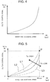
- FIG. 4 is a graph showing the clutch characteristic curve.
- the clutch characteristic curve is one representing the relation between the target fan rotational speed Nft and the clutch control signal Sc-cc and is a curve by which, as shown in FIG. 4 , the clutch control signal Sc-cc is unmistakably determined upon determination of the target fan rotational speed Nft.
- the clutch characteristic curve can be generated experimentally by inputting connection signals to the clutch 13 connected to the engine 11 that is being driven at a fixed rotational speed and then, by measuring respective rotational speeds of the output shaft 81 of the clutch 13 that is rotated in response to the respective connection signals.
- FIG. 5 is a graph showing clutch characteristic curves for respective clutch oil temperatures.
- the clutch 13 changes the characteristic in dependence on the clutch oil temperature To.
- a clutch characteristic curve L1 is taken as a base
- the clutch characteristic curve is shifted like a clutch characteristic curve L2 to the upper left of the clutch characteristic curve L1, that is, comes close to a straight line linking the origin (0, 0) to a point P (Nftmax, 100) to be exact.
- the clutch characteristic curve becomes a convex shape toward the lower right like a clutch characteristic curve L3.
- the drag torque becomes small as the temperature rises and becomes large as the temperature drops.
- the friction force on the friction discs 83, 84 becomes dominant, so that the fan rotation speed changes in proportion to the clutch control signal Sc-cc.
- the drag torque added to the friction force on the friction discs 83, 84 causes the rotation transmission to become large, so that the fan rotational speed becomes high even when the friction of the clutch is small.
- FIG. 6 is a graph showing clutch characteristic curves for respective engine rotational speeds.
- the drag torque of the clutch 13 becomes large as the rotational speed difference between the input shaft 80 and the output shaft 81 of the clutch 13 becomes large.
- the rotational speed of the input shaft 80 of the clutch 13 becomes the maximum rotational speed of the output shaft 81, and thus, where the clutch characteristic curve L1 is taken as the base, when the engine rotational speed Ne becomes low, the clutch characteristic curve has the maximum value shifted like the clutch characteristic curve L2 to the left of the clutch characteristic curve L1, so that the curve comes close to a straight line linking the origin (0, 0) to a point P2 (Nft2, 100).
- the clutch characteristic curve has the maximum value shifted to the right of the clutch characteristic curve L1, so that the curve deviates from a straight line linking the origin (0, 0) to a point P3 (Nftmax, 100) to become a convex shape toward the lower right.
- the clutch characteristic curve changes variously in dependence on the change in the clutch oil temperature To and the change in the engine rotational speed Ne. Therefore, in the present example useful for understanding the present invention, a plurality of clutch characteristic curves is stored in the clutch characteristic curve storage module 62a.
- FIG. 7 is a diagram block showing the way of calculating the target fan rotational speed Nft by the target fan rotational speed calculation module 60.
- the target fan rotational speed calculation module 60 has a lookup table 70 taking the clutch connection demand Sc-e on the axis of abscissas and the target fan rotational speed Nft on the axis of ordinate.
- a clutch connection demand Sc-e is inputted
- a target fan rotational speed Nft is determined by the lookup table 70 to be outputted.
- the lookup table 70 has target fan rotational speeds Nft that are set to become required fan rotational speeds meeting the clutch connection demands Sc-e.
- FIG. 8 is a detailed block diagram showing the way of calculating a clutch control signal Sc-fb by the feedback control module 61.
- the feedback control module 61 has a gain amplifier 71, an adder 72, a proportional gain amplifier 73, an integration gain amplifier 74, a differential gain amplifier 75, an integrator 76, a differentiator 77 and an adder 78.
- the feedback control module 61 when having the actual fan rotational speed Nf and the target fan rotational speed Nft inputted to the feedback control module 61, multiplies the actual fan rotational speed Nf and -1 (minus one) by the gain amplifier 71 and calculates the difference ⁇ Nf between the product and the target fan rotational speed Nft.
- the difference ⁇ Nf is made to diverge into three signals, of which a first signal is multiplied by a gain Kp at the proportional gain amplifier 73, a second signal is multiplied by a gain Ki at the integration gain amplifier 74 and is then integrated at the integrator 76, and a third signal is multiplied by a gain Kd at the differential gain amplifier 75 and is then differentiated at the differentiator 77.
- These three signals are added by the adder 78 and is outputted as the clutch control signal Sc-fb.
- the use as I (Integral) control becomes possible.
- the gain values of the proportional gain amplifier 73, the integration gain amplifier 74 and the differential gain amplifier 75 are experimentally calculated and set as those values that do not cause divergence nor oscillation.
- FIG. 9 is a detailed block diagram showing the way of calculating the clutch control signal Sc-cc by the clutch command calculation module 62.
- the clutch characteristic curve storage module 62a stores clutch characteristic curves LUT1 through LUTn.
- the value of "n" is determined as an adequate number in dependence on the range in use of the engine rotational speed, the range of the clutch oil temperature To and the interval at which the clutch characteristic curve is created.
- the interval at which the clutch characteristic curve is created is preferable to be, at a minimum, every 200 rpm of the engine rotational speed and every 10 degrees of the clutch oil temperature.
- the clutch command calculation module 62 chooses one clutch characteristic curve 79 meeting the clutch oil temperature To and the engine rotational speed Ne inputted to the clutch command calculation module 62 from the clutch characteristic curves LUT1 through LUTn stored in the clutch characteristic curve storage module 62a.
- the clutch command calculation module 62 applies the target fan rotational speed Nft to the chosen clutch characteristic curve 79 to extract and output a clutch control signal Sc-cc meeting the target fan rotational speed Nft.
- the clutch control signal Sc-cc and the clutch control signal Sc-fb calculated in this way are added at the adder 64 as mentioned earlier, and the added value is outputted from the controller 50 to the clutch 13 as the clutch control signal Sc meeting the target fan rotational speed Nft. Therefore, the operation of the pressure control valve 27 is controlled in accordance with the clutch control signal Sc. As a consequence, the pressure in the piston chamber 87 becomes a desired value, and the output shaft 81 of the clutch 13 is rotated at a rotational speed taking the drag torque into consideration.
- the operation of the clutch 13 is controlled in dependence on the clutch control signal Sc that is generated from the clutch control signal Sc-cc taking the clutch condition in the actual state into consideration and the clutch control signal Sc-fb taking into consideration the divergence between the target value and the present value of the fan rotational speed which divergence is caused by the abrasion of the clutch 13 and the deterioration of oil. Accordingly, it becomes possible to obtain the fan rotational speed quickly (high in responsibility) and accurately, and hence, it is possible to decrease an excessive fan power and to lessen the quantity of fuel consumption.
- FIG. 10 is a function block diagram showing an internal configuration of the controller 50 in the clutch control device according to the first embodiment.
- the principal feature of the first embodiment resides in that the controller 50 is configured to further include an oil deterioration judging module 62b for judging the deterioration of the engine oil and a clutch characteristic curve correction module 63 for correcting the clutch characteristic curve. Therefore, the following description will be made mainly regarding these featured portions, while description will be omitted about the configurations that are the same or identical with those in the foregoing example useful for understanding the present invention.
- the clutch characteristic curve correction module 63 receives the actual fan rotational speed Nf, the clutch oil temperature To, the engine rotational speed Ne and the clutch control signal Sc and generates a clutch characteristic curve correction signal Sm by calculation.
- the clutch characteristic curve correction signal Sm is inputted to the clutch characteristic curve storage module 62a, and the clutch characteristic curve storage module 62a corrects the clutch characteristic curve stored in the clutch characteristic curve storage module 62a.
- the correction frequency of the clutch characteristic curve is preferable to be the degree of once a day. This is because making the correction frequency high results in the interference with the complement of the difference in the rotational speed which complement is given by the feedback control, and thus causes a hunting to occur whereby it becomes difficult to control the fan rotational speed.
- the clutch characteristic curve correction module 63 has a correction signal storage module 63a storing the clutch characteristic curve correction signal Sm.
- the clutch characteristic curve correction signal Sm calculated during the driving of the engine 11 is once stored in the correction signal storage module 63a. Then, in the stop processing of the engine 11, the clutch characteristic curve correction signal Sm is transmitted to the clutch characteristic curve storage module 62a, and the clutch characteristic curve is corrected. That is, the clutch characteristic curve is corrected each time the operation of the hydraulic excavator is stopped.
- FIG. 11 is a graph showing a clutch characteristic curve before a correction and that after the correction.
- the clutch characteristic curve correction signal Sm is defined by a correction clutch characteristic curve number LUTm, a correction target rotational speed Nfm and a correction clutch control signal Scm.
- the clutch characteristic curve storage module 62a when receiving the clutch characteristic curve correction signal Sm from the clutch characteristic curve correction module 63, calls out the clutch characteristic curve of the correction clutch characteristic curve number LUTm and replaces the clutch control signal for the correction target rotational speed Nfm by a correction clutch control signal Scm.
- This correction is executed on every clutch characteristic curve correction signal Sm received, and the corrected clutch characteristic curve is newly stored (updated) in the clutch characteristic curve storage module 62a. In this way, at the time of the operation start of the hydraulic excavator, the operation of the clutch 13 can be controlled at all times in accordance with the newest clutch characteristic curve. Therefore, it is possible to keep the rotational speed of the fan 12 always in the optimum state.
- the clutch command calculation module 62 has the oil deterioration judging module 62b that judges the deterioration of oil. Further, for the purpose of judging oil deterioration, in the clutch characteristic curve storage module 62a, a plurality of clutch characteristic curves in an oil deterioration situation shown in FIG. 12 , for example, are stored each in association with the clutch oil temperatures To and the engine rotational speeds Ne.
- FIG. 12 is a graph showing the comparison between the present clutch characteristic curve and a clutch characteristic curve in the situation of oil deterioration.
- the oil deterioration judging module 62b compares the present clutch characteristic curve with the clutch characteristic curve in the situation of oil deterioration and, if the both are approximate, issues a warning to a warning transmitter (alarm) 65 to urge the change of the oil (engine oil) (refer to FIG. 10 ).
- a warning transmitter (alarm) 65 to urge the change of the oil (engine oil) (refer to FIG. 10 ).
- the clutch characteristic curve in the situation of oil deterioration it can be done that the clutch characteristic is measured on the oil having been used for the time period in use becoming a standard for oil change, for example, the period of 2000 hours and is stored as the clutch characteristic curve in the situation of oil deterioration.
- FIG. 13 is a graph describing the way of judging the deterioration of the engine oil
- FIG. 14 is a graph describing a range for judging the deterioration of the engine oil.
- the oil deterioration judging module 62b picks up the differences throughout the target fan rotational speeds between the present clutch characteristic curve as the objective for judgment and the clutch characteristic curve in the situation of oil deterioration, then compares the average (mean) of the differences with a threshold value ⁇ Sc-th for deterioration judgment, and, if the average is less than the threshold value ⁇ Sc-th, judges that the oil has been deteriorated.
- the range for judging the oil deterioration may be determined by the comparison only in the state that the engine rotational speed is held at the maximum rotational speed.
- the range may be determined in the way of picking up the differences between the present clutch characteristic curve and the clutch characteristic curve in the situation of oil deterioration over the range of the engine rotational speeds from a high idling to the maximum rotational speed, then calculating the average of all of the differences, and finally comparing the average with the threshold value ⁇ Sc-th for deterioration judgment.
- FIG. 15 is a flowchart showing the procedure for correcting the clutch characteristic curve by the controller 50
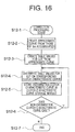
- FIG. 16 is a flowchart showing a detailed procedure for a correction step defined in FIG. 15 .
- the control begins at a time point when the engine 11 is brought into driving, that is, a time point when the operation of the hydraulic excavator is started (step S1), and the clutch connection demand Sc-e, the actual fan rotational speed Nf, the clutch oil temperature To and the engine rotational speed Ne are inputted from the engine controller 25 of the engine 11 to the controller 50 (step S2).
- the target fan rotational speed calculation module 60 calculates the target fan rotational speed Nft from the clutch connection demand Sc-e inputted at the step S2 (step S3).
- the feedback control module 61 calculates the clutch control signal Sc-fb from the target fan rotational speed Nft calculated at the step S3 and the actual fan rotational speed Nf inputted at the step S2 (step S4).
- the clutch command calculation module 62 chooses a clutch characteristic curve optimum to the present state whose curve corresponds to the clutch oil temperature To and the engine rotational speed Ne both inputted at the step S2, from the plurality of clutch characteristic curves stored in the clutch characteristic curve storage module 62a (step S5). Then, the clutch command calculation module 62 calculates the clutch control signal Sc-cc from the clutch characteristic curve chosen at the step S5 and the target fan rotational speed Nft calculated at the step S3 (step S6).
- the adder 64 adds the clutch control signal Sc-fb calculated at the step S4 and the clutch control signal Sc-cc calculated at the step S6 to obtain the clutch control signal Sc (step S7).
- the controller 50 outputs the clutch control signal Sc calculated at the step S7 to the clutch 13 (step S8).
- the clutch characteristic curve correction module 63 creates the clutch characteristic curve correction signal Sm from the clutch control signal Sc calculated at the step S8 and the actual fan rotational speed Nf, the clutch oil temperature To and the engine rotational speed Ne all inputted at the step S2 (step S9).
- the clutch characteristic curve correction module 63 stores the clutch characteristic curve correction signal Sm created at step S9 in the correction signal storage module 63a during the driving of the engine 11 (step S10) .
- step S11 judges whether or not the engine 11 has presently come into a stop sequence.
- the program proceeds to a step S12 if the engine 11 has come into the stop sequence, but returns to the step S2 if the engine 11 has not come into the stop sequence.
- step S12 the clutch characteristic curve correction signal Sm stored in the correction signal storage module 63a is outputted to the clutch characteristic curve storage module 62a. Then, the correction processing for the clutch characteristic curve is executed based on the clutch characteristic curve correction signal Sm. The details of the processing at the step S12 will be described with reference to FIG. 16 .
- step S12-1 the clutch characteristic curve storage module 62a creates an approximate curve of the clutch characteristic from the accumulated clutch characteristic curve correction signals Sm (step S12-2) and creates table values for a clutch characteristic curve LUT from the created approximated curve (step S12-3).
- the clutch characteristic curve storage module 62a makes an overwriting on the clutch characteristic curve corresponding to the table values of the clutch characteristic curve LUT (step S12-4) and stores the overwritten clutch characteristic curve in the clutch characteristic curve storage module 62a (step S12-5).
- the program returns to step S12-4 if there exists any clutch characteristic curve having been not overwritten, but terminates the correction processing if not any (step S12-7). Then, the program is returned to the routine in FIG. 15 , wherein after executing the stop processing for the engine 11 (step S13), the controller 50 finishes the processing (step S14).
- the compensation of the clutch characteristic curve can be made by the clutch characteristic curve correction module 63, it is possible to control the rotational speed of the fan 12 more accurately with the present clutch state taken into consideration. Further, by judging the deterioration of the engine oil by the oil deterioration judging module 62b and by urging, by the use of the warning transmitter 65, the user to perform the change of the engine oil, it is possible to change the engine oil at an adequate timing, and it thus becomes possible to prevent the engine from being shortened in service life and from falling in a failure and hence to decrease the frequency of the repair and replacement of the engine.
- the first embodiment is configured so that the oil deterioration judging module 62b judges the deterioration of the engine oil and issues a warning.
- the oil deterioration judging module 62b judges the deterioration of the engine oil and issues a warning.
Landscapes
- Engineering & Computer Science (AREA)
- General Engineering & Computer Science (AREA)
- Physics & Mathematics (AREA)
- Mechanical Engineering (AREA)
- Fluid Mechanics (AREA)
- Combustion & Propulsion (AREA)
- Chemical & Material Sciences (AREA)
- General Physics & Mathematics (AREA)
- Automation & Control Theory (AREA)
- Electromagnetism (AREA)
- Hydraulic Clutches, Magnetic Clutches, Fluid Clutches, And Fluid Joints (AREA)
- Control Of Positive-Displacement Air Blowers (AREA)
- Control Of Vehicle Engines Or Engines For Specific Uses (AREA)
Claims (5)
- Kupplungssteuereinrichtung für eine Arbeitsmaschine, die eine Kraftmaschine (11), eine Nasskupplung (13), die mit der Kraftmaschine (11) verbunden ist, einen Lüfter (12), der mit einer Ausgangswelle (81) der Kupplung (13) verbunden ist, einen Kraftmaschinendrehzahlsensor (32), der zum Detektieren der Drehzahl der Kraftmaschine (11) ausgelegt ist, einen Öltemperatursensor (33), der zum Detektieren einer Kupplungsöltemperatur ausgelegt ist, einen Lüfterdrehzahlsensor (31), der zum Detektieren der Drehzahl des Lüfters (12) ausgelegt ist, und eine Steuereinheit (50), die zum Steuern des Betriebs der Kupplung (13) ausgelegt ist, umfasst, wobei
die Steuereinheit (50) Folgendes enthält:ein Soll-Lüfterdrehzahlberechnungsmodul (60), das konfiguriert ist, eine Soll-Lüfterdrehzahl für den Lüfter (12) anhand eines eingegebenen Kupplungsverbindungsbedarfs zu berechnen;ein Kupplungsanweisungsberechnungsmodul (62), das konfiguriert ist, eine Kupplungskennlinie aus den mehreren Kupplungskennlinien anhand der Detektionssignale, die vom Öltemperatursensor (33) und dem Kraftmaschinendrehzahlsensor (32) ausgegeben werden, zu wählen und unter Bezugnahme auf die gewählte Kupplungskennlinie ein erstes Kupplungssteuersignal, das der Soll-Lüfterdrehzahl entspricht, auszugeben;ein Rückkopplungssteuerungsmodul (61), das konfiguriert ist, anhand der Differenz zwischen der Soll-Lüfterdrehzahl und einer Ist-Lüfterdrehzahl des Lüfters (12), die vom Lüfterdrehzahlsensor (31) ausgegeben wird, ein zweites Kupplungssteuersignal auszugeben; undeinen Addierer (64), der konfiguriert ist, das erste Kupplungssteuersignal und das zweite Kupplungssteuersignal zu addieren, um ein drittes Kupplungssteuersignal zur Kupplung (13) auszugeben, gekennzeichnet durchein Kupplungskennlinienspeichermodul (62a), das konfiguriert ist, in Verbindung mit den Öltemperaturen der Kupplung (13) und den Drehzahlen der Kraftmaschine (11) mehrere Kupplungskennlinien zu speichern, die jeweils das Verhältnis zwischen den Soll-Lüfterdrehzahlen und Steuersignalen für die Kupplung (13) vorgeben, wobei mehrere Kupplungskennlinien und mehrere Kupplungskennlinien für einen Zustand von verschlechtertem Öl der Kupplung, undein Ölverschlechterungsbeurteilungsmodul (62b), das konfiguriert ist, die Verschlechterung des Öls im Vergleich der Kupplungskennlinie, die der Kupplungsöltemperatur und der Drehzahl der Kraftmaschine (11) entspricht, mit der Kupplungskennlinie in der Situation einer Ölverschlechterung zu beurteilen. - Kupplungssteuereinrichtung für die Arbeitsmaschine nach Anspruch 1, wobei
das Ölverschlechterungsbeurteilungsmodul (62b) konfiguriert ist, die Differenzen über die Soll-Lüfterdrehzahlen zwischen der voreingestellten Kupplungskennlinie als das Ziel zur Beurteilung und der Kupplungskennlinie in der Situation einer Ölverschlechterung aufzunehmen, um den Durchschnitt (Mittelwert) der Differenzen mit einem Schwellenwert ΔSc-th zur Verschlechterungsbeurteilung zu vergleichen, und dann, wenn der Durchschnitt geringer als der Schwellenwert ΔSc-th ist, zu beurteilen, dass sich das Öl verschlechtert hat. - Kupplungssteuereinrichtung für die Arbeitsmaschine nach Anspruch 1, die ferner Folgendes umfasst:
einen Alarm, der konfiguriert ist, Informationen zum Ergebnis einer Beurteilung des Ölverschlechterungsbeurteilungsmoduls (62b) auszugeben. - Kupplungssteuereinrichtung für die Arbeitsmaschine nach Anspruch 1, wobei die Steuereinheit (50) ferner Folgendes umfasst:
ein Kupplungskennlinienkorrekturmodul (63), das konfiguriert ist, die Ist-Lüfterdrehzahl, die Kupplungsöltemperatur, die Drehzahl der Kraftmaschine (11) und das dritte Kupplungssteuersignal als Eingaben aufzunehmen und ein Kupplungskennlinienkorrektursignal zum Korrigieren der Kupplungskennlinie, die im Kupplungskennlinienspeichermodul (62a) gespeichert ist, auszugeben, wobei das Kupplungskennlinienspeichermodul (62) konfiguriert ist, die Kupplungskennlinie, die in ihm gespeichert ist, anhand des Kupplungskennlinienkorrektursignals, das durch das Kupplungskennlinienkorrekturmodul (63) erstellt wurde, zu korrigieren. - Kupplungssteuereinrichtung für die Arbeitsmaschine nach Anspruch 4, wobei die Steuereinheit (50) ferner Folgendes enthält:ein Korrektursignalspeichermodul (63a), das konfiguriert ist, das Kupplungskennlinienkorrektursignal, das durch das Kupplungskennlinienkorrekturmodul (63) erstellt wurde, zu speichern, wobeidas Kupplungskennlinienkorrekturmodul (63) konfiguriert ist, das Kupplungskennlinienkorrektursignal, das im Korrektursignalspeichermodul (63a) gespeichert ist, zum Zeitpunkt des Anhaltens der Kraftmaschine (11) auszugeben.
Applications Claiming Priority (1)
| Application Number | Priority Date | Filing Date | Title |
|---|---|---|---|
| JP2016192116A JP6539629B2 (ja) | 2016-09-29 | 2016-09-29 | 作業機械のクラッチ制御装置 |
Publications (2)
| Publication Number | Publication Date |
|---|---|
| EP3301318A1 EP3301318A1 (de) | 2018-04-04 |
| EP3301318B1 true EP3301318B1 (de) | 2019-05-08 |
Family
ID=58314083
Family Applications (1)
| Application Number | Title | Priority Date | Filing Date |
|---|---|---|---|
| EP17159093.8A Active EP3301318B1 (de) | 2016-09-29 | 2017-03-03 | Kupplungssteuerungsvorrichtung für arbeitsmaschine |
Country Status (4)
| Country | Link |
|---|---|
| US (1) | US10107341B2 (de) |
| EP (1) | EP3301318B1 (de) |
| JP (1) | JP6539629B2 (de) |
| CN (1) | CN107882894B (de) |
Families Citing this family (9)
| Publication number | Priority date | Publication date | Assignee | Title |
|---|---|---|---|---|
| US10753366B2 (en) * | 2017-10-26 | 2020-08-25 | Gary GOTTSCHALK | Automatic control systems for frost fans |
| KR102552164B1 (ko) * | 2018-10-22 | 2023-07-05 | 현대자동차주식회사 | 차량의 냉각수 상태 판단 방법 |
| CN110195748B (zh) * | 2019-05-31 | 2021-01-01 | 广东轻工职业技术学院 | 一种变压式汽车液压式离合助力系统及方法 |
| WO2021224742A1 (en) * | 2020-05-05 | 2021-11-11 | Lusetti, Lea | A drive transmission with a hydraulic clutch having a radial inlet for the hydraulic fluid |
| CN112145278B (zh) * | 2020-06-30 | 2022-03-15 | 东风马勒热系统有限公司 | 混合动力型电机电控硅油风扇离合器 |
| CN112031916A (zh) * | 2020-09-04 | 2020-12-04 | 北京理工大学 | 发动机冷却风扇调速控制系统、装置及终端设备 |
| CN112963237B (zh) * | 2021-03-17 | 2022-04-26 | 潍柴动力股份有限公司 | 一种检测电控硅油离合器的运行状态的方法、装置和设备 |
| CN113586223B (zh) * | 2021-08-27 | 2022-11-29 | 潍柴动力股份有限公司 | 电控硅油风扇的转速控制方法及装置、车辆 |
| US12228206B1 (en) * | 2024-02-26 | 2025-02-18 | Allison Transmission, Inc. | Control systems to dampen output shaft oscillations, vehicles and transmissions incorporating the same, and methods therefor |
Family Cites Families (16)
| Publication number | Priority date | Publication date | Assignee | Title |
|---|---|---|---|---|
| JPS58163831A (ja) * | 1982-03-19 | 1983-09-28 | Fuji Heavy Ind Ltd | 車輛用電磁式クラツチのコイル温度検出装置 |
| DE4100372A1 (de) | 1991-01-09 | 1992-07-16 | Fichtel & Sachs Ag | Anordnung zur regelung des schlupfs einer automatisierten reibungskupplung |
| DE19710384A1 (de) * | 1997-03-13 | 1998-09-17 | Behr Gmbh & Co | Drehzahlregeleinrichtung für eine Flüssigkeitsreibungskupplung |
| US6648115B2 (en) * | 2001-10-15 | 2003-11-18 | General Motors Corporation | Method for slip power management of a controllable viscous fan drive |
| DE10307106B3 (de) * | 2003-02-19 | 2004-10-07 | Borgwarner Inc., Auburn Hills | Vorrichtung zur Regelung der Drehzahl des Antriebdrehteils einer Viskositätskupplung |
| JP2005351286A (ja) * | 2004-06-08 | 2005-12-22 | Shin Caterpillar Mitsubishi Ltd | 入出力回転数比可変型クラッチの制御装置 |
| US7311185B2 (en) * | 2004-09-23 | 2007-12-25 | Gm Global Technology Operations, Inc. | Method for thermal management for a controllable viscous fan drive |
| JP4753278B2 (ja) * | 2004-10-12 | 2011-08-24 | 臼井国際産業株式会社 | 外部制御式ファンクラッチの制御方法 |
| GB2419690B (en) * | 2004-10-30 | 2009-06-17 | Ford Global Tech Llc | Improvements in or relating to the control of an engine cooling fan. |
| US7708127B2 (en) * | 2007-02-06 | 2010-05-04 | Gm Global Technology Operations, Inc. | Fluid model control of electro-viscous fan clutch |
| DE102008026554B4 (de) * | 2008-06-03 | 2022-12-15 | Magna powertrain gmbh & co kg | Verfahren zum Steuern einer Kupplungseinheit, sowie Drehmomentübertragungsanordnung |
| JP5446177B2 (ja) * | 2008-09-03 | 2014-03-19 | 日産自動車株式会社 | 冷却ファン制御装置 |
| WO2012083976A1 (en) * | 2010-12-20 | 2012-06-28 | Volvo Lastvagnar Ab | Method and system for calibrating an estimated clutch characteristic curve |
| EP2530273B1 (de) * | 2011-06-01 | 2020-04-08 | Joseph Vögele AG | Baumaschine mit automatischer Lüfterdrehzahlregelung |
| DE102011105507B4 (de) * | 2011-06-24 | 2022-02-17 | Schaeffler Technologies AG & Co. KG | Verfahren zur Steuerung einer automatisierten Reibungskupplung |
| US9188221B2 (en) * | 2014-02-20 | 2015-11-17 | GM Global Technology Operations LLC | Adaptive control of a flow control solenoid valve |
-
2016
- 2016-09-29 JP JP2016192116A patent/JP6539629B2/ja not_active Expired - Fee Related
-
2017
- 2017-03-02 CN CN201710121223.7A patent/CN107882894B/zh not_active Expired - Fee Related
- 2017-03-03 EP EP17159093.8A patent/EP3301318B1/de active Active
- 2017-03-07 US US15/451,455 patent/US10107341B2/en active Active
Non-Patent Citations (1)
| Title |
|---|
| None * |
Also Published As
| Publication number | Publication date |
|---|---|
| US10107341B2 (en) | 2018-10-23 |
| EP3301318A1 (de) | 2018-04-04 |
| JP2018054048A (ja) | 2018-04-05 |
| JP6539629B2 (ja) | 2019-07-03 |
| CN107882894B (zh) | 2019-08-27 |
| US20180087587A1 (en) | 2018-03-29 |
| CN107882894A (zh) | 2018-04-06 |
Similar Documents
| Publication | Publication Date | Title |
|---|---|---|
| EP3301318A1 (de) | Kupplungssteuerungsvorrichtung für arbeitsmaschine | |
| JP4097715B2 (ja) | トルク伝達装置の制御方法およびこの方法を実施するためのトルク伝達装置 | |
| US7146263B2 (en) | Predictive load management system | |
| US8489298B2 (en) | Desired torque converter clutch slip feedback recovery algorithm for tip-in maneuvers | |
| US20100082211A1 (en) | Clutch controlling apparatus for vehicle | |
| US9046174B2 (en) | Coefficient of friction correction device for belt-type continuously variable transmission | |
| JPH0472108B2 (de) | ||
| CA2475535A1 (en) | Method and system for controlling engine temperature by engine derating | |
| US20120031723A1 (en) | System and method for controlling engagement of a lockup clutch in a torque converter | |
| CN109296723A (zh) | 一种锁止离合器半接合点的自学习方法及装置 | |
| JP6267250B2 (ja) | 油圧回路の異常検知装置、及び、油圧回路の異常検知方法 | |
| US8538649B2 (en) | System and method for managing accumulator effects during engagement of a lockup clutch in a torque converter | |
| KR20190097425A (ko) | 차량용 전동식 오일펌프 제어 방법 | |
| JP5732555B2 (ja) | 電動オイルポンプの制御装置 | |
| KR20160059018A (ko) | Tcu 유압 이상 점검 방법 | |
| JP4768766B2 (ja) | 建設機械の監視装置 | |
| US11333210B1 (en) | Method for controlling air-conditioning compressor, compressor and motor vehicle | |
| JP2017120028A (ja) | エンジン及びその制御方法 | |
| KR102173922B1 (ko) | 하이브리드 구동 시스템에서의 내연기관 손실 토크 적응 방법 및 그 장치 | |
| US20060219509A1 (en) | System and method for controlling engagement of a clutch | |
| US20230048509A1 (en) | Method for Adapting a Biting Point of a Hydraulically Actuated Hybrid Disengaging Clutch | |
| KR20170005226A (ko) | Eop 로터 마모진단 방법 | |
| US20240068562A1 (en) | Method and Control Unit for Operating a Drive Train of a Vehicle | |
| KR102051388B1 (ko) | 차량용 무단 변속기 유압 제어 장치 및 방법 | |
| KR20160007814A (ko) | 하이브리드 차량의 전동식 오일 펌프의 제어방법 및 그 제어 시스템. |
Legal Events
| Date | Code | Title | Description |
|---|---|---|---|
| PUAI | Public reference made under article 153(3) epc to a published international application that has entered the european phase |
Free format text: ORIGINAL CODE: 0009012 |
|
| STAA | Information on the status of an ep patent application or granted ep patent |
Free format text: STATUS: REQUEST FOR EXAMINATION WAS MADE |
|
| 17P | Request for examination filed |
Effective date: 20170428 |
|
| AK | Designated contracting states |
Kind code of ref document: A1 Designated state(s): AL AT BE BG CH CY CZ DE DK EE ES FI FR GB GR HR HU IE IS IT LI LT LU LV MC MK MT NL NO PL PT RO RS SE SI SK SM TR |
|
| AX | Request for extension of the european patent |
Extension state: BA ME |
|
| GRAP | Despatch of communication of intention to grant a patent |
Free format text: ORIGINAL CODE: EPIDOSNIGR1 |
|
| STAA | Information on the status of an ep patent application or granted ep patent |
Free format text: STATUS: GRANT OF PATENT IS INTENDED |
|
| INTG | Intention to grant announced |
Effective date: 20190116 |
|
| RIN1 | Information on inventor provided before grant (corrected) |
Inventor name: ARAI, MASATSUGU Inventor name: OSAKA, TADASHI Inventor name: TANAKA, TAKAAKI Inventor name: KOUNO, RYUJI Inventor name: IKARI, TAKANOBU Inventor name: FUKUDA, NAOKI |
|
| GRAS | Grant fee paid |
Free format text: ORIGINAL CODE: EPIDOSNIGR3 |
|
| GRAA | (expected) grant |
Free format text: ORIGINAL CODE: 0009210 |
|
| STAA | Information on the status of an ep patent application or granted ep patent |
Free format text: STATUS: THE PATENT HAS BEEN GRANTED |
|
| AK | Designated contracting states |
Kind code of ref document: B1 Designated state(s): AL AT BE BG CH CY CZ DE DK EE ES FI FR GB GR HR HU IE IS IT LI LT LU LV MC MK MT NL NO PL PT RO RS SE SI SK SM TR |
|
| REG | Reference to a national code |
Ref country code: GB Ref legal event code: FG4D |
|
| REG | Reference to a national code |
Ref country code: CH Ref legal event code: EP Ref country code: AT Ref legal event code: REF Ref document number: 1130603 Country of ref document: AT Kind code of ref document: T Effective date: 20190515 |
|
| REG | Reference to a national code |
Ref country code: DE Ref legal event code: R096 Ref document number: 602017003717 Country of ref document: DE Ref country code: IE Ref legal event code: FG4D |
|
| REG | Reference to a national code |
Ref country code: NL Ref legal event code: MP Effective date: 20190508 |
|
| REG | Reference to a national code |
Ref country code: LT Ref legal event code: MG4D |
|
| PG25 | Lapsed in a contracting state [announced via postgrant information from national office to epo] |
Ref country code: SE Free format text: LAPSE BECAUSE OF FAILURE TO SUBMIT A TRANSLATION OF THE DESCRIPTION OR TO PAY THE FEE WITHIN THE PRESCRIBED TIME-LIMIT Effective date: 20190508 Ref country code: HR Free format text: LAPSE BECAUSE OF FAILURE TO SUBMIT A TRANSLATION OF THE DESCRIPTION OR TO PAY THE FEE WITHIN THE PRESCRIBED TIME-LIMIT Effective date: 20190508 Ref country code: LT Free format text: LAPSE BECAUSE OF FAILURE TO SUBMIT A TRANSLATION OF THE DESCRIPTION OR TO PAY THE FEE WITHIN THE PRESCRIBED TIME-LIMIT Effective date: 20190508 Ref country code: ES Free format text: LAPSE BECAUSE OF FAILURE TO SUBMIT A TRANSLATION OF THE DESCRIPTION OR TO PAY THE FEE WITHIN THE PRESCRIBED TIME-LIMIT Effective date: 20190508 Ref country code: NL Free format text: LAPSE BECAUSE OF FAILURE TO SUBMIT A TRANSLATION OF THE DESCRIPTION OR TO PAY THE FEE WITHIN THE PRESCRIBED TIME-LIMIT Effective date: 20190508 Ref country code: NO Free format text: LAPSE BECAUSE OF FAILURE TO SUBMIT A TRANSLATION OF THE DESCRIPTION OR TO PAY THE FEE WITHIN THE PRESCRIBED TIME-LIMIT Effective date: 20190808 Ref country code: PT Free format text: LAPSE BECAUSE OF FAILURE TO SUBMIT A TRANSLATION OF THE DESCRIPTION OR TO PAY THE FEE WITHIN THE PRESCRIBED TIME-LIMIT Effective date: 20190908 Ref country code: FI Free format text: LAPSE BECAUSE OF FAILURE TO SUBMIT A TRANSLATION OF THE DESCRIPTION OR TO PAY THE FEE WITHIN THE PRESCRIBED TIME-LIMIT Effective date: 20190508 Ref country code: AL Free format text: LAPSE BECAUSE OF FAILURE TO SUBMIT A TRANSLATION OF THE DESCRIPTION OR TO PAY THE FEE WITHIN THE PRESCRIBED TIME-LIMIT Effective date: 20190508 |
|
| PG25 | Lapsed in a contracting state [announced via postgrant information from national office to epo] |
Ref country code: BG Free format text: LAPSE BECAUSE OF FAILURE TO SUBMIT A TRANSLATION OF THE DESCRIPTION OR TO PAY THE FEE WITHIN THE PRESCRIBED TIME-LIMIT Effective date: 20190808 Ref country code: RS Free format text: LAPSE BECAUSE OF FAILURE TO SUBMIT A TRANSLATION OF THE DESCRIPTION OR TO PAY THE FEE WITHIN THE PRESCRIBED TIME-LIMIT Effective date: 20190508 Ref country code: LV Free format text: LAPSE BECAUSE OF FAILURE TO SUBMIT A TRANSLATION OF THE DESCRIPTION OR TO PAY THE FEE WITHIN THE PRESCRIBED TIME-LIMIT Effective date: 20190508 Ref country code: GR Free format text: LAPSE BECAUSE OF FAILURE TO SUBMIT A TRANSLATION OF THE DESCRIPTION OR TO PAY THE FEE WITHIN THE PRESCRIBED TIME-LIMIT Effective date: 20190809 |
|
| REG | Reference to a national code |
Ref country code: AT Ref legal event code: MK05 Ref document number: 1130603 Country of ref document: AT Kind code of ref document: T Effective date: 20190508 |
|
| PG25 | Lapsed in a contracting state [announced via postgrant information from national office to epo] |
Ref country code: DK Free format text: LAPSE BECAUSE OF FAILURE TO SUBMIT A TRANSLATION OF THE DESCRIPTION OR TO PAY THE FEE WITHIN THE PRESCRIBED TIME-LIMIT Effective date: 20190508 Ref country code: AT Free format text: LAPSE BECAUSE OF FAILURE TO SUBMIT A TRANSLATION OF THE DESCRIPTION OR TO PAY THE FEE WITHIN THE PRESCRIBED TIME-LIMIT Effective date: 20190508 Ref country code: CZ Free format text: LAPSE BECAUSE OF FAILURE TO SUBMIT A TRANSLATION OF THE DESCRIPTION OR TO PAY THE FEE WITHIN THE PRESCRIBED TIME-LIMIT Effective date: 20190508 Ref country code: SK Free format text: LAPSE BECAUSE OF FAILURE TO SUBMIT A TRANSLATION OF THE DESCRIPTION OR TO PAY THE FEE WITHIN THE PRESCRIBED TIME-LIMIT Effective date: 20190508 Ref country code: RO Free format text: LAPSE BECAUSE OF FAILURE TO SUBMIT A TRANSLATION OF THE DESCRIPTION OR TO PAY THE FEE WITHIN THE PRESCRIBED TIME-LIMIT Effective date: 20190508 Ref country code: EE Free format text: LAPSE BECAUSE OF FAILURE TO SUBMIT A TRANSLATION OF THE DESCRIPTION OR TO PAY THE FEE WITHIN THE PRESCRIBED TIME-LIMIT Effective date: 20190508 |
|
| REG | Reference to a national code |
Ref country code: DE Ref legal event code: R097 Ref document number: 602017003717 Country of ref document: DE |
|
| PG25 | Lapsed in a contracting state [announced via postgrant information from national office to epo] |
Ref country code: SM Free format text: LAPSE BECAUSE OF FAILURE TO SUBMIT A TRANSLATION OF THE DESCRIPTION OR TO PAY THE FEE WITHIN THE PRESCRIBED TIME-LIMIT Effective date: 20190508 Ref country code: IT Free format text: LAPSE BECAUSE OF FAILURE TO SUBMIT A TRANSLATION OF THE DESCRIPTION OR TO PAY THE FEE WITHIN THE PRESCRIBED TIME-LIMIT Effective date: 20190508 |
|
| PLBE | No opposition filed within time limit |
Free format text: ORIGINAL CODE: 0009261 |
|
| STAA | Information on the status of an ep patent application or granted ep patent |
Free format text: STATUS: NO OPPOSITION FILED WITHIN TIME LIMIT |
|
| PG25 | Lapsed in a contracting state [announced via postgrant information from national office to epo] |
Ref country code: TR Free format text: LAPSE BECAUSE OF FAILURE TO SUBMIT A TRANSLATION OF THE DESCRIPTION OR TO PAY THE FEE WITHIN THE PRESCRIBED TIME-LIMIT Effective date: 20190508 |
|
| 26N | No opposition filed |
Effective date: 20200211 |
|
| PG25 | Lapsed in a contracting state [announced via postgrant information from national office to epo] |
Ref country code: PL Free format text: LAPSE BECAUSE OF FAILURE TO SUBMIT A TRANSLATION OF THE DESCRIPTION OR TO PAY THE FEE WITHIN THE PRESCRIBED TIME-LIMIT Effective date: 20190508 |
|
| PG25 | Lapsed in a contracting state [announced via postgrant information from national office to epo] |
Ref country code: SI Free format text: LAPSE BECAUSE OF FAILURE TO SUBMIT A TRANSLATION OF THE DESCRIPTION OR TO PAY THE FEE WITHIN THE PRESCRIBED TIME-LIMIT Effective date: 20190508 |
|
| PG25 | Lapsed in a contracting state [announced via postgrant information from national office to epo] |
Ref country code: MC Free format text: LAPSE BECAUSE OF FAILURE TO SUBMIT A TRANSLATION OF THE DESCRIPTION OR TO PAY THE FEE WITHIN THE PRESCRIBED TIME-LIMIT Effective date: 20190508 |
|
| REG | Reference to a national code |
Ref country code: CH Ref legal event code: PL |
|
| REG | Reference to a national code |
Ref country code: BE Ref legal event code: MM Effective date: 20200331 |
|
| PG25 | Lapsed in a contracting state [announced via postgrant information from national office to epo] |
Ref country code: LU Free format text: LAPSE BECAUSE OF NON-PAYMENT OF DUE FEES Effective date: 20200303 |
|
| PG25 | Lapsed in a contracting state [announced via postgrant information from national office to epo] |
Ref country code: CH Free format text: LAPSE BECAUSE OF NON-PAYMENT OF DUE FEES Effective date: 20200331 Ref country code: LI Free format text: LAPSE BECAUSE OF NON-PAYMENT OF DUE FEES Effective date: 20200331 Ref country code: FR Free format text: LAPSE BECAUSE OF NON-PAYMENT OF DUE FEES Effective date: 20200331 Ref country code: IE Free format text: LAPSE BECAUSE OF NON-PAYMENT OF DUE FEES Effective date: 20200303 |
|
| PG25 | Lapsed in a contracting state [announced via postgrant information from national office to epo] |
Ref country code: BE Free format text: LAPSE BECAUSE OF NON-PAYMENT OF DUE FEES Effective date: 20200331 |
|
| GBPC | Gb: european patent ceased through non-payment of renewal fee |
Effective date: 20210303 |
|
| PG25 | Lapsed in a contracting state [announced via postgrant information from national office to epo] |
Ref country code: GB Free format text: LAPSE BECAUSE OF NON-PAYMENT OF DUE FEES Effective date: 20210303 |
|
| PGFP | Annual fee paid to national office [announced via postgrant information from national office to epo] |
Ref country code: DE Payment date: 20220203 Year of fee payment: 6 |
|
| PG25 | Lapsed in a contracting state [announced via postgrant information from national office to epo] |
Ref country code: MT Free format text: LAPSE BECAUSE OF FAILURE TO SUBMIT A TRANSLATION OF THE DESCRIPTION OR TO PAY THE FEE WITHIN THE PRESCRIBED TIME-LIMIT Effective date: 20190508 Ref country code: CY Free format text: LAPSE BECAUSE OF FAILURE TO SUBMIT A TRANSLATION OF THE DESCRIPTION OR TO PAY THE FEE WITHIN THE PRESCRIBED TIME-LIMIT Effective date: 20190508 |
|
| PG25 | Lapsed in a contracting state [announced via postgrant information from national office to epo] |
Ref country code: MK Free format text: LAPSE BECAUSE OF FAILURE TO SUBMIT A TRANSLATION OF THE DESCRIPTION OR TO PAY THE FEE WITHIN THE PRESCRIBED TIME-LIMIT Effective date: 20190508 Ref country code: IS Free format text: LAPSE BECAUSE OF FAILURE TO SUBMIT A TRANSLATION OF THE DESCRIPTION OR TO PAY THE FEE WITHIN THE PRESCRIBED TIME-LIMIT Effective date: 20190908 |
|
| REG | Reference to a national code |
Ref country code: DE Ref legal event code: R119 Ref document number: 602017003717 Country of ref document: DE |
|
| PG25 | Lapsed in a contracting state [announced via postgrant information from national office to epo] |
Ref country code: DE Free format text: LAPSE BECAUSE OF NON-PAYMENT OF DUE FEES Effective date: 20231003 |