EP3301299B1 - Pulsationsdämpfer für kompressoren - Google Patents
Pulsationsdämpfer für kompressoren Download PDFInfo
- Publication number
- EP3301299B1 EP3301299B1 EP17189170.8A EP17189170A EP3301299B1 EP 3301299 B1 EP3301299 B1 EP 3301299B1 EP 17189170 A EP17189170 A EP 17189170A EP 3301299 B1 EP3301299 B1 EP 3301299B1
- Authority
- EP
- European Patent Office
- Prior art keywords
- damper
- illustratively
- inner chamber
- inlet
- outlet
- Prior art date
- Legal status (The legal status is an assumption and is not a legal conclusion. Google has not performed a legal analysis and makes no representation as to the accuracy of the status listed.)
- Active
Links
Images




Classifications
-
- F—MECHANICAL ENGINEERING; LIGHTING; HEATING; WEAPONS; BLASTING
- F04—POSITIVE - DISPLACEMENT MACHINES FOR LIQUIDS; PUMPS FOR LIQUIDS OR ELASTIC FLUIDS
- F04C—ROTARY-PISTON, OR OSCILLATING-PISTON, POSITIVE-DISPLACEMENT MACHINES FOR LIQUIDS; ROTARY-PISTON, OR OSCILLATING-PISTON, POSITIVE-DISPLACEMENT PUMPS
- F04C29/00—Component parts, details or accessories of pumps or pumping installations, not provided for in groups F04C18/00 - F04C28/00
- F04C29/0021—Systems for the equilibration of forces acting on the pump
- F04C29/0035—Equalization of pressure pulses
-
- F—MECHANICAL ENGINEERING; LIGHTING; HEATING; WEAPONS; BLASTING
- F04—POSITIVE - DISPLACEMENT MACHINES FOR LIQUIDS; PUMPS FOR LIQUIDS OR ELASTIC FLUIDS
- F04B—POSITIVE-DISPLACEMENT MACHINES FOR LIQUIDS; PUMPS
- F04B39/00—Component parts, details, or accessories, of pumps or pumping systems specially adapted for elastic fluids, not otherwise provided for in, or of interest apart from, groups F04B25/00 - F04B37/00
- F04B39/0027—Pulsation and noise damping means
-
- F—MECHANICAL ENGINEERING; LIGHTING; HEATING; WEAPONS; BLASTING
- F04—POSITIVE - DISPLACEMENT MACHINES FOR LIQUIDS; PUMPS FOR LIQUIDS OR ELASTIC FLUIDS
- F04B—POSITIVE-DISPLACEMENT MACHINES FOR LIQUIDS; PUMPS
- F04B39/00—Component parts, details, or accessories, of pumps or pumping systems specially adapted for elastic fluids, not otherwise provided for in, or of interest apart from, groups F04B25/00 - F04B37/00
- F04B39/0027—Pulsation and noise damping means
- F04B39/0055—Pulsation and noise damping means with a special shape of fluid passage, e.g. bends, throttles, diameter changes, pipes
-
- F—MECHANICAL ENGINEERING; LIGHTING; HEATING; WEAPONS; BLASTING
- F04—POSITIVE - DISPLACEMENT MACHINES FOR LIQUIDS; PUMPS FOR LIQUIDS OR ELASTIC FLUIDS
- F04B—POSITIVE-DISPLACEMENT MACHINES FOR LIQUIDS; PUMPS
- F04B39/00—Component parts, details, or accessories, of pumps or pumping systems specially adapted for elastic fluids, not otherwise provided for in, or of interest apart from, groups F04B25/00 - F04B37/00
- F04B39/0027—Pulsation and noise damping means
- F04B39/0055—Pulsation and noise damping means with a special shape of fluid passage, e.g. bends, throttles, diameter changes, pipes
- F04B39/0061—Pulsation and noise damping means with a special shape of fluid passage, e.g. bends, throttles, diameter changes, pipes using muffler volumes
-
- F—MECHANICAL ENGINEERING; LIGHTING; HEATING; WEAPONS; BLASTING
- F04—POSITIVE - DISPLACEMENT MACHINES FOR LIQUIDS; PUMPS FOR LIQUIDS OR ELASTIC FLUIDS
- F04C—ROTARY-PISTON, OR OSCILLATING-PISTON, POSITIVE-DISPLACEMENT MACHINES FOR LIQUIDS; ROTARY-PISTON, OR OSCILLATING-PISTON, POSITIVE-DISPLACEMENT PUMPS
- F04C18/00—Rotary-piston pumps specially adapted for elastic fluids
- F04C18/08—Rotary-piston pumps specially adapted for elastic fluids of intermeshing-engagement type, i.e. with engagement of co-operating members similar to that of toothed gearing
- F04C18/12—Rotary-piston pumps specially adapted for elastic fluids of intermeshing-engagement type, i.e. with engagement of co-operating members similar to that of toothed gearing of other than internal-axis type
- F04C18/14—Rotary-piston pumps specially adapted for elastic fluids of intermeshing-engagement type, i.e. with engagement of co-operating members similar to that of toothed gearing of other than internal-axis type with toothed rotary pistons
- F04C18/16—Rotary-piston pumps specially adapted for elastic fluids of intermeshing-engagement type, i.e. with engagement of co-operating members similar to that of toothed gearing of other than internal-axis type with toothed rotary pistons with helical teeth, e.g. chevron-shaped, screw type
-
- F—MECHANICAL ENGINEERING; LIGHTING; HEATING; WEAPONS; BLASTING
- F04—POSITIVE - DISPLACEMENT MACHINES FOR LIQUIDS; PUMPS FOR LIQUIDS OR ELASTIC FLUIDS
- F04C—ROTARY-PISTON, OR OSCILLATING-PISTON, POSITIVE-DISPLACEMENT MACHINES FOR LIQUIDS; ROTARY-PISTON, OR OSCILLATING-PISTON, POSITIVE-DISPLACEMENT PUMPS
- F04C29/00—Component parts, details or accessories of pumps or pumping installations, not provided for in groups F04C18/00 - F04C28/00
- F04C29/06—Silencing
-
- F—MECHANICAL ENGINEERING; LIGHTING; HEATING; WEAPONS; BLASTING
- F04—POSITIVE - DISPLACEMENT MACHINES FOR LIQUIDS; PUMPS FOR LIQUIDS OR ELASTIC FLUIDS
- F04C—ROTARY-PISTON, OR OSCILLATING-PISTON, POSITIVE-DISPLACEMENT MACHINES FOR LIQUIDS; ROTARY-PISTON, OR OSCILLATING-PISTON, POSITIVE-DISPLACEMENT PUMPS
- F04C29/00—Component parts, details or accessories of pumps or pumping installations, not provided for in groups F04C18/00 - F04C28/00
- F04C29/06—Silencing
- F04C29/065—Noise dampening volumes, e.g. muffler chambers
-
- F—MECHANICAL ENGINEERING; LIGHTING; HEATING; WEAPONS; BLASTING
- F04—POSITIVE - DISPLACEMENT MACHINES FOR LIQUIDS; PUMPS FOR LIQUIDS OR ELASTIC FLUIDS
- F04D—NON-POSITIVE-DISPLACEMENT PUMPS
- F04D29/00—Details, component parts, or accessories
- F04D29/66—Combating cavitation, whirls, noise, vibration or the like; Balancing
- F04D29/661—Combating cavitation, whirls, noise, vibration or the like; Balancing especially adapted for elastic fluid pumps
- F04D29/663—Sound attenuation
- F04D29/665—Sound attenuation by means of resonance chambers or interference
-
- G—PHYSICS
- G10—MUSICAL INSTRUMENTS; ACOUSTICS
- G10K—SOUND-PRODUCING DEVICES; METHODS OR DEVICES FOR PROTECTING AGAINST, OR FOR DAMPING, NOISE OR OTHER ACOUSTIC WAVES IN GENERAL; ACOUSTICS NOT OTHERWISE PROVIDED FOR
- G10K11/00—Methods or devices for transmitting, conducting or directing sound in general; Methods or devices for protecting against, or for damping, noise or other acoustic waves in general
- G10K11/16—Methods or devices for protecting against, or for damping, noise or other acoustic waves in general
- G10K11/161—Methods or devices for protecting against, or for damping, noise or other acoustic waves in general in systems with fluid flow
-
- F—MECHANICAL ENGINEERING; LIGHTING; HEATING; WEAPONS; BLASTING
- F05—INDEXING SCHEMES RELATING TO ENGINES OR PUMPS IN VARIOUS SUBCLASSES OF CLASSES F01-F04
- F05D—INDEXING SCHEME FOR ASPECTS RELATING TO NON-POSITIVE-DISPLACEMENT MACHINES OR ENGINES, GAS-TURBINES OR JET-PROPULSION PLANTS
- F05D2250/00—Geometry
- F05D2250/50—Inlet or outlet
- F05D2250/52—Outlet
Definitions
- the present disclosure relates, generally, to dampers and, more particularly, to dampers for gas compressors.
- Compressors for example, gas compressors can produce noise, vibration, pulsation, and/or other incidental forces and/or effects. Different types of compressors may be particularly prone to certain incidental forces and/or effects. Reducing such incidental forces and/or effects can increase operational life and reliability, and can reduce maintenance requirements.
- US 4,050,539 shows an exhaust apparatus for internal combustion engines comprising an outer pipe, an inner pipe of approximately the same diameter as an exhaust pipe and a plurality of helical passages between the inner and outer pipes.
- the silencer may be generally cylindrical with a funnel shaped inlet end, and include a small-diameter inlet pipe, a coil spring and perforated flat plate.
- US 2012/171069 A1 shows a shunt pulsation trap for a screw compressor.
- the trap has a pair of multi-helical-lobe rotors housed in a compressor chamber for propelling gas flow from a suction port to a discharge port.
- US 2006/124385 A1 shows a modular system of pressure pulsation dampeners for use in an air compressor system.
- the modular system components may be selected and interconnected to form a silencer having desired physical and pressure pulsation characteristics.
- US2015/198179 A1 shows a system in which a pressure pulse dampener is in fluid communication with a compressed fluid.
- the pulse dampener is operable for reducing pressure pulsations within the fluid.
- a check valve can be in fluid communication with the pulse dampener to prevent reverse flow of the compressed fluid.
- This document does not show a number of partitions dividing the outer chamber into sections, the number of partitions each extending between the outer chamber and the inner chamber; and a damper plate arranged between the base portion and the head portion of each of the number of partitions.
- a damper for reducing pulsation from a compressor comprising an outer chamber defining an outer cavity therein, the outer chamber being arranged to pass flow from an inlet to an outlet thereof, an inner chamber arranged within the outer cavity and defining an inner cavity therein, the inner chamber being arranged to pass flow from an inlet to an outlet thereof.
- the damper includes a number of partitions dividing the outer chamber into sections, the number of partitions each extending between the outer chamber and the inner chamber.
- the sections of the outer chamber are connected with each other near the inlet of the inner chamber to form an inlet manifold and are connected with each other near the outlet of the inner chamber to form an outlet manifold.
- the sections of the outer chamber extend between the respective inlet and outlet manifolds and define respective flow paths.
- the inlet of the inner chamber is connected with the inlet manifold and the outlet of the inner chamber is connected with the outlet manifold.
- a housing forms at least a portion of the outer chamber, the housing including a body and a cap fastened to the body to define at least a portion of the outer cavity.
- the body may form a base portion of the outer chamber and may form the inner chamber.
- the cap may form a head portion of the outer chamber. The body forms a base portion of each of the number of partitions.
- each base portion may include a fastener hole defined therethrough for receiving a fastener to secure the body with the compressor.
- the head portion of each of the number of partitions may be arranged to prevent removal of the fastener from the fastener hole of the corresponding base portion.
- the damper includes a damper plate arranged between the base portion and the head portion of each of the number of partitions.
- the damper plate may be a perforated plate arranged to span across the outlet of the inner chamber to receive at least a portion of flow therethrough.
- the damper plate may be attached to the head portion of the number of partitions. In some embodiments, the damper plate may be attached to the head portion with at least one fastener and at least one of the inner chamber and the base portions of the number of partitions may be arranged to prevent removal of the at least one fastener when the cap is fastened to the body.
- a damper for reducing pulsation from a compressor may include an outer chamber defining an outer cavity therein, the outer chamber being arranged to pass flow from an inlet to an outlet thereof, an inner chamber arranged within the outer cavity and defining an inner cavity therein, the inner chamber being arranged to pass flow from an inlet to an outlet thereof, and a number of partitions dividing the outer chamber into sections that are each connected with the inlet and outlet of the outer chamber to form parallel flow paths.
- the inlet of the inner chamber may include a number of inlet openings defined through an inlet wall of the inner chamber.
- the inlet wall may have a conical shape that is convex on an outer side thereof to guide at least some flow through the sections.
- a first flow passage may be defined from the inlet of the outer chamber, through at least one of the sections, to the outlet of the outer chamber.
- a second flow passage may be defined from the inlet of the inner chamber, through the inner chamber, and through the outlet of the inner chamber. The first flow passage and the second flow passage may be arranged in parallel with each other.
- the damper may include a perforated plate arranged near the outlet of the inner chamber. In some embodiments, the second flow passage may be further defined through the perforated plate.
- a damper system for reducing pulsation from a compressor which includes a first stage damper, and a second stage damper, wherein the first and second stage dampers are in accordance with the first aspect.
- the first stage damper may be attached to the compressor to receive partially compressed air, pass the partially compressed air from the inlet to the outlet of the outlet chamber thereof, and to discharge the partially compressed into the compressor for further compression
- the second stage damper is attached to the compressor to receive fully compressed air, pass the fully compressed air from the inlet to the outlet of the outlet chamber thereof, and to discharge the fully compressed air for use.
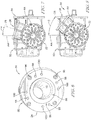
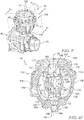
- a compressor assembly includes a compressor 10 having a damper system 12 for reducing pressure pulsations.
- the damper system 12 illustratively includes a first stage damper 14 and a second stage damper 16 each secured to the compressor 10.
- the compressor 10 is illustratively embodiment as a displacement-type gas compressor, namely a screw compressor, but in some embodiments may include any fluid compressor.
- the compressor 10 illustratively includes two compression stages 18, 20, but in some embodiments may include any suitable number of compression stages.
- the compressor 10 illustratively compresses a fluid (illustratively gas) in a first compression stage 18 to an initial pressure (partially compressed).
- the first stage damper 14 illustratively receives a flow of partially compressed fluid from the first compression stage 18, dampens and discharges the flow.
- the flow discharged from the first stage damper (still partially compressed) reenters the compressor 10 for further compression in a second compression stage 20.
- at least one portion of the flow discharged from the first stage damper 14 may be cooled by at least one cooler (interstage cooler) before reentering the compressor 10, and/or may be distributed for use at the initial pressure.
- the compressor 10 illustratively compresses the flow of partially compressed fluid (discharged from the first stage damper 14) in a second compression stage 20 to a final pressure (fully compressed).
- the second stage damper 16 illustratively receives a flow of fully compressed fluid from the second compression stage 20, dampens and discharges the flow.
- the flow discharged from the second stage damper 16 (fully compressed) is discharged for use at the final pressure.
- the flow discharged from the second stage damper may be further conditioned, for example but without limitation, dehumidified according to final design requirements.
- the compressor 10 is embodied as a displacement-type compressor.
- the compression stages 18, 20 are illustratively embodied as screw compression stages.
- Displacement compression can naturally result in incidental forces, for example but without limitation, pressure pulsations, due to the mechanics of operation.
- Pressure pulsations illustratively include naturally imposed pressure fluctuations (e.g., peaks and valleys) resultant from the cyclic nature of certain compression mechanics. Stresses on the compressor and/or related equipment can be reduced by damping (calming) the pressure fluctuations effectively. Effectively reducing the pressure pulsations can increase operational life, increase reliability, and/or reduce maintenance requirements.
- the first stage damper 14 illustratively includes a housing 22 that forms an intake 24 and a discharge 26.
- the intake 24 is illustratively connected to the compressor 10 to receive a flow of partially compressed fluid.
- the flow of partially compressed fluid passes through the housing 22 for dampening and exits through the discharge 26.
- the flow from the discharge 26 illustratively returns to the compressor 10 for further pressurization.
- Auxiliary components, such as piping components, returning the flow to the compressor 10 from the discharge 26, are implied but not shown to reveal detail.
- the first stage damper 14 illustratively includes an outer chamber 28 formed at least partially by the housing 22.
- the outer chamber 28 illustratively includes an outer cavity 30 defined therein.
- the outer chamber 28 and the outer cavity 30 are each generally spherical and are generally symmetrical about a central axis 15.
- the outer chamber 28 illustratively includes an inlet 32 and an outlet 34 each defined as openings of the outer chamber 28 that connect with the outer cavity 30.
- Partitions 38 (discussed below in more detail) illustratively divide the outer chamber 28 into sections 36.
- the sections 36 illustratively connect with each other at opposite ends to form manifolds 40, 42 which connect the outer chamber 28 with an inner chamber 44.
- the inner chamber 44 is illustratively arranged within the outer cavity 30 of the outer chamber 28.
- the inner chamber 44 illustratively includes an inner cavity 46 defined therein.
- the inner chamber 44 and the inner cavity are generally spherical and are generally symmetrical about the central axis 15.
- the inner chamber 44 illustratively includes an inlet 48 and an outlet 50 each embodied as openings of the inner chamber 44 that connect with the inner cavity 46.
- the inlet 48 and outlet 50 are arranged at opposite axial ends of the inner chamber 44 and connect with the manifolds 40, 42.
- a damper plate 52 is illustratively arranged within the manifold 42 near the outlet of the inner chamber 44 as shown in FIG. 3 .
- the damper plate 52 illustratively includes perforations 54 extending therethrough parallel to the axis 15.
- the damper plate 52 is arranged spaced apart from the inner chamber 44 to define a clearance 56 therebetween.
- portions of flow that pass through the inner chamber 44 and exit through the outlet 50 illustratively form an inner flow, and can either pass through the perforations 54 or the clearance 56 into the manifold 42.
- Portions of flow that pass from the inlet 32 through the sections 36 of the outer chamber 28 illustratively form an outer flow.
- the inlet 48 of the inner chamber 44 illustratively connects with the manifold 40.
- the inlet 48 illustratively includes four openings 58 (two of which are shown in the cross-sectional view of FIG. 3 ) extending through a wall 60 of the inner chamber 44.
- the wall 60 at the inlet 48 illustratively has a generally convex shape on an outer side 62 that faces the manifold 40 and the inlet 32 of the outer chamber 28 to guide at least a portion of the incoming flow from the inlet 32 towards the sections 36.
- the openings 58 of the inlet 48 illustratively penetrate through the wall 60 and connect the manifold 40 with the inner cavity 46.
- the openings 58 are distributed evenly about the axis 15 and extend through the wall 60 in a direction that is generally parallel to the axis 15 and complimentary to the major direction of flow through the inlet 32 of the outer chamber.
- the inlet 48 illustratively forms a flow divider guiding a portion of flow through its openings 58 (and out through its outlet 50) and another portion of flow into the sections 36.
- the different portions of flow illustratively pass through the first stage damper 14 in parallel with each other between the intake 24 and the discharge 26.
- the partitions 38 illustratively extend between the outer chamber 28 and the inner chamber 44 to define the sections 36 of the outer chamber 28.
- the partitions 38 illustratively extend axially through the outer cavity 30.
- the partitions 38 are embodied as walls distributed evenly about the axis 15 and provide structural support to the housing 22 while separating the outer chamber 28 into the sections 36.
- the sections 36 illustratively form distinct flow paths arranged in parallel with each other and connecting with each other to form the manifolds 40, 42.
- the inner chamber 44 in combination with the damper plate 52, illustratively dissipate pressure pulsations from the compressor 10.
- the distinct flow paths provided by the sections 36 illustratively assist in reducing pressure pulsations within the total flow from the compressor 10.
- the housing 22 illustratively includes a body 62, a cap 64, and a base 66 that collectively compose the outer chamber 28.
- the cap 64 and the base illustratively attach to the body 62 at opposite ends to enclose the outer chamber 28.
- the discharge 26 illustratively includes a discharge limb 68 that extends from the body 62 and defines a discharge passage 69 extending therethrough and connecting with the outlet 34 of the outer chamber 28.
- the discharge limb 68 extends from the body 62 radially away from the axis 15.
- the discharge passage 69 is illustratively directly connected with only a single section 36 of the outer chamber 28 and communicates with the manifold 42 (and the other section 36) through the single section 36.
- the partitions 38 each include a base portion 70 and a head portion 72.
- Each base portion 70 illustratively extends between the outer chamber 28 and the inner chamber 44 and includes an axial end 74 arranged near the manifold 42.
- each base portion 70 is illustratively formed integrally with each of the inner and outer chambers 28, 44, but in some embodiments, may be formed separately or integrally with only one of the chambers 28, 44.
- Each head portion 72 illustratively extends from the cap 64 into the outer chamber 28 to an inner end 76 opposite the axial end 74 of the base portion 70.
- the damper plate 52 is illustratively arranged between the base portion 70 and the head portion 72 of each partition 38 to define the clearance 56 with the inner chamber 44.
- the damper plate 52 is illustratively attached to each head portion 72 by fasteners 78 that extend through the damper plate 52 and connect with the respective head portions 72.
- the fasteners 78 are bolts having outer threads for engagement with complimentary inner threads of the head portions 72.
- each partition 38 illustratively includes a fastener hole 80 extending axially therethrough from the axial end 74 towards the base 66.
- the fastener holes 80 are illustratively arranged to receive fasteners 82 therethrough to connect with the base 66 for securing the base 66 to the body 62.
- Each fastener 82 illustratively includes a head 84 that is recessed within a larger portion of the fastener hole 80.
- the fasteners 82 are bolts having external threads for engagement with complimentary internal threads of the base 66.
- the fasteners 78, 82 are illustratively prevented from removal from their secured positions by the arrangement of the base and head portions 70, 72 of the partitions 38 and/or the inner chamber 44.
- the head portion 72 of the partitions 38 is arranged in close proximity to the fasteners 82 and their fastener holes 80 and if any fastener 82 (or any portion thereof, for example, broken fragment) began to exit its fastener hole 80 within the base portion 70, the fastener 82 would contact the respective head portion 72 and be prevented from entering into the flow paths within the first stage damper 14 (and downstream).
- FIG. 5 the fasteners 78, 82 are illustratively prevented from removal from their secured positions by the arrangement of the base and head portions 70, 72 of the partitions 38 and/or the inner chamber 44.
- the head portion 72 of the partitions 38 is arranged in close proximity to the fasteners 82 and their fastener holes 80 and if any fastener 82 (or any portion thereof, for example, broken fragment) began to exit
- the base portion 70 of each partition 38 and/or the inner chamber 44 are arranged in close proximity to the fasteners 78 and if any fastener 78 began to exit connection with the head portion 72, the fastener 78 would contact the respective base portion 70 and/or the inner chamber 44 and be prevented from entering into the flow paths within the first stage damper 14 (and downstream).
- Such interference arrangement of the fasteners 78, 82 can prevent accidental entrainment of fasteners into the flow paths of the dampers 14, 16 (and into the compressor 10) while the dampers 14, 16 are in their assembled state.
- the base 66 illustratively forms the intake 24.
- the intake 24 illustratively includes an intake limb 86 and an intake passage 88 extending through the intake limb 86 to receive partially compressed fluid from the compressor 10.
- the intake passage 88 is illustratively formed as an intake nozzle.
- the intake passage 88 illustratively includes a reduced diameter section 90 disposed at one end 92, an increased diameter section 94 at an opposite end near the inlet 32, and a mid-section 95 extending between the reduced diameter section 90 and the increased diameter section 94 with a taper to transition between the sections 90, 94 as shown in FIG. 5 .
- the intake passage 88 illustratively includes curvature, as shown in FIG. 5 , which turns counter-clockwise proceeding from the reduced diameter section 90 to the increased diameter section 94 to generally align with the central axis 15 near the inlet 32.
- the base 66 of the housing 22 illustratively includes a number of mounting holes 96 extending therethrough to receive main fasteners for connecting the base 66 with the compressor 10.
- the base 66 illustratively includes attachment holes 98, 100 each arranged to correspond with one of the fasteners 82 for securing the base 66 with the body 62.
- Each attachment holes 98, 100 illustratively includes the inner threads that are complimentary with the outer threads of the fasteners 82 for receiving the fasteners 82 secured therein.
- the body is secure to the base 66 with a second orientation (as shown in FIG. 8 ).
- the body 62 can thus be selectively oriented relative to the base 66.
- the first orientation is shown.
- the first stage damper 14 is arranged such that the discharge 26 has a high steepness for connection downstream.
- the compressor 10 is illustratively adapted for use as an air-cooled system in which an air-cooled intercooler cools the partially compressed air from the discharge 26 of the first stage damper 14.
- the compressor 10 may be adapted for use with any suitable type of downstream connection, including but not limited to any suitable air/liquid/gas-cooled intercooler, treatment device, and/or transfer peripherals.
- a center line 25 of the discharge 26 extends at an angle ⁇ from a vertical line AA (in the arrangement as shown in FIG. 7 ).
- the angle is about 18 degrees, but in some embodiments, may be about 15 to about 20 degrees.
- the second orientation is shown.
- the first stage damper 14 is arranged is arranged such that the discharge 26 has a moderate steepness for connection downstream.
- the compressor 10 is illustratively adapted for use as an liquid-cooled system in which a liquid-cooled intercooler cools the partially compressed air from the discharge 26 of the first stage damper 14.
- the compressor 10 may be adapted for use with any suitable type of downstream connection, including but not limited to any suitable air/liquid/gas-cooled intercooler, treatment device, and/or transfer peripherals.
- the center line 25 of the discharge 26 extends at an angle ⁇ from a vertical line AA (in the arrangement as shown in FIG. 8 ).
- the angle is about 20 degrees, but in some embodiments, may be about 18 to about 25 degrees.
- the second stage damper 16 illustratively includes a housing 102 that forms an intake 104 and a discharge 106.
- the intake 104 is illustratively connected to the compressor 10 to receive a flow of fully compressed fluid.
- the flow of fully compressed fluid passes through the housing 102 for dampening and exits through the discharge 106.
- the flow from the discharge 106 is illustratively distributed for use.
- the second stage damper 16 illustratively includes an outer chamber 108 formed at least partially by the housing 102.
- the outer chamber 108 illustratively includes an outer cavity 110 defined therein.
- the outer chamber 108 and the outer cavity 110 are each generally spherical and are generally symmetrical about a central axis 35.
- the outer chamber 108 illustratively includes an inlet 112 and an outlet 114 each defined as openings of the outer chamber 108 that connect with the outer cavity 110.
- Partitions 38 (discussed below in more detail) illustratively divide the outer chamber 108 into sections 118.
- the sections 118 illustratively connect with each other at opposite ends to form manifolds 120, 122 which connect the outer chamber 108 with an inner chamber 124.
- the inner chamber 124 is illustratively arranged within the outer cavity 110 of the outer chamber 108.
- the inner chamber 124 illustratively includes an inner cavity 126 defined therein.
- the inner chamber 124 and the inner cavity 126 are generally spherical and are generally symmetrical about the central axis 35.
- the inner chamber 124 illustratively includes an inlet 128 and an outlet 130 each embodied as openings of the inner chamber 124 that connect with inner cavity 126.
- the inlet 128 and outlet 130 are arranged at opposite axial ends of the inner chamber 124 and connect with the manifolds 120, 122.
- a damper plate 132 is illustratively arranged within the manifold 122 near the outlet 130 of the inner chamber 124 as shown in FIG. 10 .
- the damper plate 132 illustratively includes perforations 134 extending therethrough parallel to the axis 35.
- the damper plate 132 is arranged spaced apart from the inner chamber 124 to define a clearance 136 therebetween. Flow that passes through the inner chamber 124 and exits through the outlet 130 can either pass through the perforations 134 or the clearance 136 into the manifold 122.
- the inlet 128 of the inner chamber 124 illustratively connects with the manifold 120.
- the inlet 128 illustratively includes four openings 138 (two of which are shown in the cross-sectional view of FIG. 10 ) extending through a wall 140 of the inner chamber 124.
- the wall 140 at the inlet 128 illustratively has a generally convex shape on an outer side 142 that faces the manifold 120 and the inlet 112 of the outer chamber 108 to guide at least a portion of the incoming flow from the inlet 112 towards the sections 118.
- the openings 138 of the inlet 128 illustratively penetrate through the wall 140 and connect the manifold 120 with the inner cavity 126.
- the openings 138 are distributed evenly about the axis 35 and extend through the wall 140 in a direction that is generally parallel to the axis 35 and complimentary to the major direction of flow through the inlet 112 of the outer chamber 108.
- the inlet 128 of the inner chamber 124 illustratively forms a flow divider guiding a portion of flow through its openings 138 (and out through its outlet 130) and another portion of flow into the sections 118.
- the flow through the sections 118 illustratively forms an (outer) flow
- the flow through the inner cavity 126 illustratively forms another (inner) flow.
- the different portions of flow (outer and inner) illustratively pass through the second stage damper 16 in parallel with each other between the intake 104 and the discharge 106.
- the partitions 116 illustratively extend radially between the outer chamber 108 and the inner chamber 124 to define the sections 118 of the outer chamber 108.
- the partitions 116 illustratively extend axially through the outer cavity 110.
- the partitions 116 are embodied as four walls distributed evenly about the axis 35.
- the partitions 116 illustratively provide structural support to the housing 102 and apportion the outer chamber 108 into the sections 118.
- the partitions 116 support the inner chamber 124 and separate the flow into different sections 118.
- the partitions 116 may include any number of walls and/or maybe arranged within uneven distribution about the axis 35.
- the sections 118 illustratively form distinct flow paths arranged in parallel with each other and connecting with each other to form the manifolds 120, 122.
- the inner chamber 124 in combination with the damper plate 52, illustratively dissipate pressure pulsations from the compressor 10.
- the distinct flow paths provided by the sections 118 illustratively assist in reducing pressure pulsations within the total flow from the compressor 10.
- the housing 102 illustratively includes a body 142 and a cap 144 that collectively compose the outer chamber 28.
- the body 142 of the second stage damper 16 forms a base 146 integrally therewith.
- the base 146 make be distinct from the body 142.
- the cap 144 illustratively attaches to the body 142 on an opposite end from the base 146 to enclose the outer chamber 108.
- the discharge 106 illustratively includes a discharge passage 148 extending through the cap 144 and connecting with the outlet 114 of the outer chamber 28.
- the discharge passage 148 is illustratively connected with the manifold 122 through the outlet 114.
- the outlet 114 is not positioned with any single section 118.
- the discharge passage 148 illustratively communicates with each section 118 through the manifold 122.
- the partitions 116 each include a base portion 150 and a head portion 152 (best shown in FIG. 10 ).
- Each base portion 150 illustratively extends radially between the outer chamber 108 and the inner chamber 124 and includes an axial end 154 arranged near the manifold 122.
- each base portion 150 is illustratively formed integrally with each of the outer and inner chambers 108, 124, but in some embodiments, may be formed separately or integrally with only one of the chambers 108, 124.
- Each head portion 152 illustratively extends from the cap 144 into the outer chamber 108 to an inner end 156 opposite the axial end 154 of the base portion 150.
- the damper plate 132 is illustratively arranged between the base portion 150 and the head portion 152 of each partition 116 to define the clearance 136 with the inner chamber 124.
- the damper plate 132 is illustratively attached to each head portion 152 by fasteners 158 that extend through the damper plate 132 and connect with the respective head portions 152.
- the fasteners 158 are bolts having outer threads for engagement with complimentary inner threads of the head portions 152.
- each partition 116 illustratively includes a fastener hole 160 extending axially therethrough from the axial end 154 through the base 146.
- the fastener holes 160 are illustratively arranged to receive fasteners 162 therethrough to connect with the compressor 10 for securing the second stage damper 16 thereto.
- Each fastener 162 illustratively includes a head 164 that is recessed within a larger portion of the fastener hole 160.
- the fasteners 162 are bolts having external threads for engagement with complimentary internal threads of the compressor 10.
- the fasteners 158, 162 are illustratively prevented from removal from their secured positions by the arrangement of the base and head portions 150, 152 of the partitions 116 and/or the inner chamber 124.
- the head portion 152 of the partitions 116 is arranged in close proximity to the fasteners 162 and their fastener holes 160 and if any fastener 162 (or any portion thereof, for example, broken fragment) began to exit its fastener hole 180 within the base portion 150, the fastener 162 would contact the respective head portion 152 and be prevented from entering into the flow paths within the second stage damper 16 (and downstream).
- FIG. 12 the fasteners 158, 162 are illustratively prevented from removal from their secured positions by the arrangement of the base and head portions 150, 152 of the partitions 116 and/or the inner chamber 124.
- the head portion 152 of the partitions 116 is arranged in close proximity to the fasteners 162 and their fastener holes 160 and if any fastener 162 (or any portion
- each partition 116 and/or the inner chamber 124 are arranged in close proximity to the fasteners 158 and if any fastener 158 began to exit from connection with the head portion 152, the fastener 158 would contact the respective base portion 150 and/or the inner chamber 124 and be prevented from entering into the flow paths within the second stage damper 16 (and downstream).
- Such interference arrangement of the fasteners 158, 182 can prevent accidental entrainment of fasteners into the flow paths of the dampers 14, 16 (and into the compressor 10) while the dampers 14, 16 are in their assembled state.
- the base 146 illustratively forms the intake 104.
- the intake 104 illustratively includes an intake limb 184 and an intake passage 186 extending through the intake limb 184 to receive partially compressed fluid from the compressor 10.
- the intake passage 186 is illustratively formed as an intake nozzle.
- the intake passage 186 illustratively includes a reduced diameter section 188 disposed at one end 190, an increased diameter section 192 at an opposite end near the inlet 112, and a mid-section 194 extending between the reduced diameter section 188 and the increased diameter section 192 with a taper to transition between the sections 188, 190.
- the intake passage 186 is straight (though with taper) and generally aligns with the central axis 35 proceeding from the reduced diameter section 188 to the increased diameter section 192.
- the present disclosure includes portions of flow through sections of outer chambers and portions of flow through inner chambers running in parallel with each other. Some of these parallel flows can be directed through a perforated damper plate. The parallel flows can increase dampening performance. According to the present disclosure, the pulsations and/or other incidental forces and/or effects of displacement-type compressors can be controlled and/or reduced effectively.
Landscapes
- Engineering & Computer Science (AREA)
- Mechanical Engineering (AREA)
- General Engineering & Computer Science (AREA)
- Physics & Mathematics (AREA)
- Combustion & Propulsion (AREA)
- Aviation & Aerospace Engineering (AREA)
- Chemical & Material Sciences (AREA)
- Fluid Mechanics (AREA)
- Acoustics & Sound (AREA)
- Multimedia (AREA)
- Compressors, Vaccum Pumps And Other Relevant Systems (AREA)
- Applications Or Details Of Rotary Compressors (AREA)
- Compressor (AREA)
Claims (8)
- Dämpfer (14) zur Reduzierung von Pulsation von einem Kompressor, wobei der Dämpfer (14) Folgendes umfasst:eine äußere Kammer (28), definierend einen äußeren Hohlraum (30) darin, wobei die äußere Kammer (28) angeordnet ist, um Strömung von einem ersten Einlass (32) zu einem ersten Auslass (34) davon passieren zu lassen,eine innere Kammer (44), angeordnet innerhalb des äußeren Hohlraums (30) und definierend einen inneren Hohlraum (46) darin, wobei die innere Kammer (44) angeordnet ist, um Strömung von einem zweiten Einlass (48) zu einem zweiten Auslass (50) davon passieren zu lassen, undeine Anzahl von Partitionen (38), die die äußere Kammer (28) in Abschnitte (36) teilen, wobei sich die Anzahl der Partitionen (38) jeweils zwischen der äußeren Kammer (28) und der inneren Kammer (44) erstrecken;wobei die Abschnitte (36) in der Nähe des zweiten Einlasses (48) miteinander verbunden sind, um einen Einlasskrümmer (40) auszubilden, in der Nähe des zweiten Auslasses (50) miteinander verbunden sind, um einen Auslasskrümmer (42) auszubilden, und sich zwischen dem Einlasskrümmer (40) und dem Auslasskrümmer (42) erstrecken, um entsprechende Strömungspfade zwischen dem ersten Einlass (32) und dem ersten Auslass (34) zu definieren, undwobei ein Gehäuse (22) mindestens einen Abschnitt der Auslasskammer (28) ausbildet, wobei das Gehäuse (22) einen Körper (62) und eine Kappe (64) beinhaltet, befestigt an dem Körper (62), um mindestens einen Abschnitt des äußeren Hohlraums (30) zu definieren,wobei der zweite Einlass (48) der inneren Kammer (44) mit dem Einlasskrümmer (40) verbunden ist und der zweite Auslass (50) der inneren Kammer (44) mit dem Auslasskrümmer (42) verbunden ist,wobei der Körper (62) einen Basisabschnitt (66) von jeder von der Anzahl von Partitionen (38) ausbildet,wobei die Kappe (64) einen Kopfabschnitt (72) von jeder von der Anzahl von Partitionen (38) ausbildet,wobei der Dämpfer ferner eine Dämpferplatte (52) umfasst, angeordnet zwischen dem Basisabschnitt (66) und dem Kopfabschnitt (72) von jeder von der Anzahl von Partitionen (38).
- Dämpfer nach Anspruch 1, wobei der Körper (62) einen Basisabschnitt (66) der äußeren Kammer (28) ausbildet und die innere Kammer (44) ausbildet.
- Dämpfer nach Anspruch 2, wobei die Kappe (64) einen Kopfabschnitt (72) der äußeren Kammer (28) ausbildet.
- Dämpfer nach einem der vorangehenden Ansprüche, wobei jeder Basisabschnitt (66) ein dort hindurch definiertes Befestigungsloch (80) zum Aufnehmen eines Befestigungselements (78) beinhaltet, um den Körper mit dem Kompressor zu sichern.
- Dämpfer nach Anspruch 4, wobei der Kopfabschnitt (72) von jeder von der Anzahl von Partitionen (38) angeordnet ist, um ein Entfernen des Befestigungselements (78) von dem Befestigungsloch (80) des entsprechenden Basisabschnitts (66) zu verhindern.
- Dämpfer nach einem der vorangehenden Ansprüche, wobei die Dämpferplatte (52) eine perforierte Platte ist, angeordnet, um den zweiten Auslass (50) der inneren Kammer (48) zu überspannen, um mindestens einen Abschnitt von Strömung dort hindurch zu empfangen.
- Dämpfer nach einem der vorangehenden Ansprüche, wobei die Dämpferplatte (52) an dem Kopfabschnitt (72) der Anzahl von Partitionen (38) mit mindestens einem Befestigungselement (78) angebracht ist, und mindestens eine von der inneren Kammer (44) und den Basisabschnitten (66) der Anzahl von Partitionen (38) angeordnet sind, um ein Entfernen des mindestens einen Befestigungselements (78) zu verhindern, wenn die Kappe an dem Körper (62) befestigt ist.
- Dämpfersystem zur Reduzierung von Pulsation von einem Kompressor, wobei das Dämpfersystem Folgendes umfasst:einen Dämpfer der ersten Stufe entsprechend einem der Ansprüche 1-7, undeinen Dämpfer der zweiten Stufe entsprechend einem der Ansprüche 1-7.
Applications Claiming Priority (1)
| Application Number | Priority Date | Filing Date | Title |
|---|---|---|---|
| US15/282,149 US10180140B2 (en) | 2016-09-30 | 2016-09-30 | Pulsation damper for compressors |
Publications (2)
| Publication Number | Publication Date |
|---|---|
| EP3301299A1 EP3301299A1 (de) | 2018-04-04 |
| EP3301299B1 true EP3301299B1 (de) | 2020-02-19 |
Family
ID=59772496
Family Applications (1)
| Application Number | Title | Priority Date | Filing Date |
|---|---|---|---|
| EP17189170.8A Active EP3301299B1 (de) | 2016-09-30 | 2017-09-04 | Pulsationsdämpfer für kompressoren |
Country Status (3)
| Country | Link |
|---|---|
| US (1) | US10180140B2 (de) |
| EP (1) | EP3301299B1 (de) |
| CN (1) | CN107882733B (de) |
Family Cites Families (28)
| Publication number | Priority date | Publication date | Assignee | Title |
|---|---|---|---|---|
| US2990907A (en) | 1959-06-11 | 1961-07-04 | Wilhelm S Everett | Acoustic filter |
| JPS5236219A (en) | 1975-09-13 | 1977-03-19 | Teruo Kashiwara | Exhaust equipment for internal combustion engine |
| US4109751A (en) * | 1976-08-26 | 1978-08-29 | Deere & Company | Noise silencer |
| SE438009B (sv) * | 1978-10-03 | 1985-03-25 | Dolmar Maschfab | Insugs- och/eller avgasljuddempare vid snabbgaende forbrenningsmotorer |
| JP2895407B2 (ja) * | 1994-12-01 | 1999-05-24 | 本田技研工業株式会社 | 吸気消音装置 |
| KR100211597B1 (ko) * | 1996-10-09 | 1999-08-02 | 오상수 | 버스 에어컨의 소음기 |
| US6220839B1 (en) | 1999-07-07 | 2001-04-24 | Copeland Corporation | Scroll compressor discharge muffler |
| JP2004270559A (ja) * | 2003-03-10 | 2004-09-30 | Honda Motor Co Ltd | 車両用吸気装置 |
| CN1542284A (zh) | 2003-05-01 | 2004-11-03 | 乐金电子(天津)电器有限公司 | 旋转式压缩机的多孔干涉型消音器 |
| JP2005042624A (ja) | 2003-07-22 | 2005-02-17 | Calsonic Kansei Corp | 圧縮機 |
| KR20060024739A (ko) | 2004-09-14 | 2006-03-17 | 삼성전자주식회사 | 다기통 압축기 |
| US20060124385A1 (en) | 2004-12-10 | 2006-06-15 | Ingersoll-Rand Company | Modular pressure pulsation dampener |
| US7549509B2 (en) | 2005-04-21 | 2009-06-23 | Ingersoll-Rand Company | Double throat pulsation dampener for a compressor |
| EP1715189B1 (de) * | 2005-04-22 | 2013-12-04 | Kaeser Kompressoren AG | Schalldämpfer ausgebildet und bestimmt für einen Kompressor |
| EP1715188A1 (de) * | 2005-04-22 | 2006-10-25 | Kaeser Kompressoren GmbH | Schalldämpfer ausgebildet und bestimmt für einen Kompressor |
| DE602006012174D1 (de) | 2006-07-03 | 2010-03-25 | Lg Electronics Inc | Spiralverdichter mit Schalldämpfer |
| CN101105177A (zh) | 2006-07-13 | 2008-01-16 | Lg电子株式会社 | 涡卷压缩机的消声器 |
| US9404499B2 (en) | 2006-12-01 | 2016-08-02 | Emerson Climate Technologies, Inc. | Dual chamber discharge muffler |
| CN101398005A (zh) | 2007-09-28 | 2009-04-01 | 乐金电子(天津)电器有限公司 | 压缩机的消音装置 |
| WO2009045187A1 (en) | 2007-10-01 | 2009-04-09 | Carrier Corporation | Screw compressor pulsation damper |
| CN101806251B (zh) | 2010-03-25 | 2012-08-22 | 北京航空航天大学 | 一种微型燃气轮机的起动控制装置以及起动控制方法 |
| US9151292B2 (en) | 2011-01-05 | 2015-10-06 | Hi-Bar Blowers, Inc. | Screw compressor with a shunt pulsation trap |
| US9732754B2 (en) | 2011-06-07 | 2017-08-15 | Hi-Bar Blowers, Inc. | Shunt pulsation trap for positive-displacement machinery |
| US9551342B2 (en) * | 2014-05-23 | 2017-01-24 | Paul Xiubao Huang | Scroll compressor with a shunt pulsation trap |
| KR102160310B1 (ko) * | 2013-03-06 | 2020-09-28 | 에이비비 터보 시스템즈 아게 | 배기가스 터보차저의 소음기 |
| US9951761B2 (en) * | 2014-01-16 | 2018-04-24 | Ingersoll-Rand Company | Aerodynamic pressure pulsation dampener |
| US9739290B2 (en) | 2014-01-16 | 2017-08-22 | Ingersoll-Rand Company | Compressor system with pressure pulsation dampener and check valve |
| CN104454548B (zh) | 2014-12-22 | 2017-02-01 | 广东美芝制冷设备有限公司 | 旋转式压缩机 |
-
2016
- 2016-09-30 US US15/282,149 patent/US10180140B2/en active Active
-
2017
- 2017-09-04 EP EP17189170.8A patent/EP3301299B1/de active Active
- 2017-09-26 CN CN201710880509.3A patent/CN107882733B/zh active Active
Non-Patent Citations (1)
| Title |
|---|
| None * |
Also Published As
| Publication number | Publication date |
|---|---|
| EP3301299A1 (de) | 2018-04-04 |
| CN107882733A (zh) | 2018-04-06 |
| CN107882733B (zh) | 2020-11-17 |
| US20180094629A1 (en) | 2018-04-05 |
| US10180140B2 (en) | 2019-01-15 |
Similar Documents
| Publication | Publication Date | Title |
|---|---|---|
| US8016071B1 (en) | Multi-stage low pressure drop muffler | |
| US10907517B2 (en) | Silencer and vehicle engine including same | |
| CN110159536B (zh) | 涡旋压缩机、空调器和车辆 | |
| CN104204532A (zh) | 制冷剂压缩机 | |
| EP3301299B1 (de) | Pulsationsdämpfer für kompressoren | |
| US2707033A (en) | Pulsation dampeners | |
| CN110067641B (zh) | 增压器再循环阀及涡轮增压器 | |
| US7494328B2 (en) | NVH and gas pulsation reduction in AC compressor | |
| CN110500261B (zh) | 一种氢燃料电池系统排气消声器 | |
| CN215244236U (zh) | 空调管路消音装置、空调制冷系统和车辆 | |
| CN221170014U (zh) | 压缩机 | |
| CN219826952U (zh) | 消声器 | |
| US20150315948A1 (en) | Modular aftertreatment assembly | |
| KR100230848B1 (ko) | 연료장치의 연료댐퍼구조 | |
| CN218669523U (zh) | 排气消声器 | |
| US20210115926A1 (en) | Modular compressor discharge system | |
| KR100882656B1 (ko) | 가변 소음기 타입 차량용 싱글 배기 장치 | |
| CN219754641U (zh) | 一种消声器总成及车辆 | |
| CN221149645U (zh) | 用于制氧机的消音器 | |
| EP2783098B1 (de) | Verbrennungsmotor und kurbelgehäuse | |
| CN112855623B (zh) | 用于冷凝器的减振装置 | |
| CN113002746B (zh) | 消声式冷却器和船舶冷却系统 | |
| CN219262493U (zh) | 消音器及车辆 | |
| CN215672500U (zh) | 具有消音腔室的中冷进气管 | |
| WO2023112177A1 (ja) | 消音器および真空排気装置 |
Legal Events
| Date | Code | Title | Description |
|---|---|---|---|
| PUAI | Public reference made under article 153(3) epc to a published international application that has entered the european phase |
Free format text: ORIGINAL CODE: 0009012 |
|
| STAA | Information on the status of an ep patent application or granted ep patent |
Free format text: STATUS: THE APPLICATION HAS BEEN PUBLISHED |
|
| AK | Designated contracting states |
Kind code of ref document: A1 Designated state(s): AL AT BE BG CH CY CZ DE DK EE ES FI FR GB GR HR HU IE IS IT LI LT LU LV MC MK MT NL NO PL PT RO RS SE SI SK SM TR |
|
| AX | Request for extension of the european patent |
Extension state: BA ME |
|
| STAA | Information on the status of an ep patent application or granted ep patent |
Free format text: STATUS: REQUEST FOR EXAMINATION WAS MADE |
|
| 17P | Request for examination filed |
Effective date: 20181004 |
|
| RBV | Designated contracting states (corrected) |
Designated state(s): AL AT BE BG CH CY CZ DE DK EE ES FI FR GB GR HR HU IE IS IT LI LT LU LV MC MK MT NL NO PL PT RO RS SE SI SK SM TR |
|
| STAA | Information on the status of an ep patent application or granted ep patent |
Free format text: STATUS: EXAMINATION IS IN PROGRESS |
|
| 17Q | First examination report despatched |
Effective date: 20190418 |
|
| GRAP | Despatch of communication of intention to grant a patent |
Free format text: ORIGINAL CODE: EPIDOSNIGR1 |
|
| STAA | Information on the status of an ep patent application or granted ep patent |
Free format text: STATUS: GRANT OF PATENT IS INTENDED |
|
| INTG | Intention to grant announced |
Effective date: 20190913 |
|
| GRAS | Grant fee paid |
Free format text: ORIGINAL CODE: EPIDOSNIGR3 |
|
| GRAA | (expected) grant |
Free format text: ORIGINAL CODE: 0009210 |
|
| STAA | Information on the status of an ep patent application or granted ep patent |
Free format text: STATUS: THE PATENT HAS BEEN GRANTED |
|
| AK | Designated contracting states |
Kind code of ref document: B1 Designated state(s): AL AT BE BG CH CY CZ DE DK EE ES FI FR GB GR HR HU IE IS IT LI LT LU LV MC MK MT NL NO PL PT RO RS SE SI SK SM TR |
|
| REG | Reference to a national code |
Ref country code: CH Ref legal event code: EP |
|
| REG | Reference to a national code |
Ref country code: DE Ref legal event code: R096 Ref document number: 602017011889 Country of ref document: DE |
|
| REG | Reference to a national code |
Ref country code: AT Ref legal event code: REF Ref document number: 1235274 Country of ref document: AT Kind code of ref document: T Effective date: 20200315 |
|
| REG | Reference to a national code |
Ref country code: IE Ref legal event code: FG4D |
|
| RAP2 | Party data changed (patent owner data changed or rights of a patent transferred) |
Owner name: INGERSOLL-RAND INDUSTRIAL U.S., INC. |
|
| REG | Reference to a national code |
Ref country code: NL Ref legal event code: MP Effective date: 20200219 |
|
| PG25 | Lapsed in a contracting state [announced via postgrant information from national office to epo] |
Ref country code: NO Free format text: LAPSE BECAUSE OF FAILURE TO SUBMIT A TRANSLATION OF THE DESCRIPTION OR TO PAY THE FEE WITHIN THE PRESCRIBED TIME-LIMIT Effective date: 20200519 Ref country code: FI Free format text: LAPSE BECAUSE OF FAILURE TO SUBMIT A TRANSLATION OF THE DESCRIPTION OR TO PAY THE FEE WITHIN THE PRESCRIBED TIME-LIMIT Effective date: 20200219 Ref country code: RS Free format text: LAPSE BECAUSE OF FAILURE TO SUBMIT A TRANSLATION OF THE DESCRIPTION OR TO PAY THE FEE WITHIN THE PRESCRIBED TIME-LIMIT Effective date: 20200219 |
|
| REG | Reference to a national code |
Ref country code: LT Ref legal event code: MG4D |
|
| PG25 | Lapsed in a contracting state [announced via postgrant information from national office to epo] |
Ref country code: HR Free format text: LAPSE BECAUSE OF FAILURE TO SUBMIT A TRANSLATION OF THE DESCRIPTION OR TO PAY THE FEE WITHIN THE PRESCRIBED TIME-LIMIT Effective date: 20200219 Ref country code: SE Free format text: LAPSE BECAUSE OF FAILURE TO SUBMIT A TRANSLATION OF THE DESCRIPTION OR TO PAY THE FEE WITHIN THE PRESCRIBED TIME-LIMIT Effective date: 20200219 Ref country code: LV Free format text: LAPSE BECAUSE OF FAILURE TO SUBMIT A TRANSLATION OF THE DESCRIPTION OR TO PAY THE FEE WITHIN THE PRESCRIBED TIME-LIMIT Effective date: 20200219 Ref country code: BG Free format text: LAPSE BECAUSE OF FAILURE TO SUBMIT A TRANSLATION OF THE DESCRIPTION OR TO PAY THE FEE WITHIN THE PRESCRIBED TIME-LIMIT Effective date: 20200519 Ref country code: IS Free format text: LAPSE BECAUSE OF FAILURE TO SUBMIT A TRANSLATION OF THE DESCRIPTION OR TO PAY THE FEE WITHIN THE PRESCRIBED TIME-LIMIT Effective date: 20200619 Ref country code: GR Free format text: LAPSE BECAUSE OF FAILURE TO SUBMIT A TRANSLATION OF THE DESCRIPTION OR TO PAY THE FEE WITHIN THE PRESCRIBED TIME-LIMIT Effective date: 20200520 |
|
| PG25 | Lapsed in a contracting state [announced via postgrant information from national office to epo] |
Ref country code: NL Free format text: LAPSE BECAUSE OF FAILURE TO SUBMIT A TRANSLATION OF THE DESCRIPTION OR TO PAY THE FEE WITHIN THE PRESCRIBED TIME-LIMIT Effective date: 20200219 |
|
| PG25 | Lapsed in a contracting state [announced via postgrant information from national office to epo] |
Ref country code: RO Free format text: LAPSE BECAUSE OF FAILURE TO SUBMIT A TRANSLATION OF THE DESCRIPTION OR TO PAY THE FEE WITHIN THE PRESCRIBED TIME-LIMIT Effective date: 20200219 Ref country code: CZ Free format text: LAPSE BECAUSE OF FAILURE TO SUBMIT A TRANSLATION OF THE DESCRIPTION OR TO PAY THE FEE WITHIN THE PRESCRIBED TIME-LIMIT Effective date: 20200219 Ref country code: SK Free format text: LAPSE BECAUSE OF FAILURE TO SUBMIT A TRANSLATION OF THE DESCRIPTION OR TO PAY THE FEE WITHIN THE PRESCRIBED TIME-LIMIT Effective date: 20200219 Ref country code: ES Free format text: LAPSE BECAUSE OF FAILURE TO SUBMIT A TRANSLATION OF THE DESCRIPTION OR TO PAY THE FEE WITHIN THE PRESCRIBED TIME-LIMIT Effective date: 20200219 Ref country code: LT Free format text: LAPSE BECAUSE OF FAILURE TO SUBMIT A TRANSLATION OF THE DESCRIPTION OR TO PAY THE FEE WITHIN THE PRESCRIBED TIME-LIMIT Effective date: 20200219 Ref country code: DK Free format text: LAPSE BECAUSE OF FAILURE TO SUBMIT A TRANSLATION OF THE DESCRIPTION OR TO PAY THE FEE WITHIN THE PRESCRIBED TIME-LIMIT Effective date: 20200219 Ref country code: PT Free format text: LAPSE BECAUSE OF FAILURE TO SUBMIT A TRANSLATION OF THE DESCRIPTION OR TO PAY THE FEE WITHIN THE PRESCRIBED TIME-LIMIT Effective date: 20200712 Ref country code: EE Free format text: LAPSE BECAUSE OF FAILURE TO SUBMIT A TRANSLATION OF THE DESCRIPTION OR TO PAY THE FEE WITHIN THE PRESCRIBED TIME-LIMIT Effective date: 20200219 Ref country code: SM Free format text: LAPSE BECAUSE OF FAILURE TO SUBMIT A TRANSLATION OF THE DESCRIPTION OR TO PAY THE FEE WITHIN THE PRESCRIBED TIME-LIMIT Effective date: 20200219 |
|
| REG | Reference to a national code |
Ref country code: AT Ref legal event code: MK05 Ref document number: 1235274 Country of ref document: AT Kind code of ref document: T Effective date: 20200219 |
|
| REG | Reference to a national code |
Ref country code: DE Ref legal event code: R097 Ref document number: 602017011889 Country of ref document: DE |
|
| PLBE | No opposition filed within time limit |
Free format text: ORIGINAL CODE: 0009261 |
|
| STAA | Information on the status of an ep patent application or granted ep patent |
Free format text: STATUS: NO OPPOSITION FILED WITHIN TIME LIMIT |
|
| REG | Reference to a national code |
Ref country code: DE Ref legal event code: R082 Ref document number: 602017011889 Country of ref document: DE Representative=s name: MURGITROYD GERMANY PATENTANWALTSGESELLSCHAFT M, DE Ref country code: DE Ref legal event code: R082 Ref document number: 602017011889 Country of ref document: DE Representative=s name: HL KEMPNER PATENTANWALT, RECHTSANWALT, SOLICIT, DE Ref country code: DE Ref legal event code: R082 Ref document number: 602017011889 Country of ref document: DE Representative=s name: MURGITROYD & COMPANY, DE |
|
| 26N | No opposition filed |
Effective date: 20201120 |
|
| PG25 | Lapsed in a contracting state [announced via postgrant information from national office to epo] |
Ref country code: IT Free format text: LAPSE BECAUSE OF FAILURE TO SUBMIT A TRANSLATION OF THE DESCRIPTION OR TO PAY THE FEE WITHIN THE PRESCRIBED TIME-LIMIT Effective date: 20200219 Ref country code: AT Free format text: LAPSE BECAUSE OF FAILURE TO SUBMIT A TRANSLATION OF THE DESCRIPTION OR TO PAY THE FEE WITHIN THE PRESCRIBED TIME-LIMIT Effective date: 20200219 |
|
| PG25 | Lapsed in a contracting state [announced via postgrant information from national office to epo] |
Ref country code: PL Free format text: LAPSE BECAUSE OF FAILURE TO SUBMIT A TRANSLATION OF THE DESCRIPTION OR TO PAY THE FEE WITHIN THE PRESCRIBED TIME-LIMIT Effective date: 20200219 Ref country code: SI Free format text: LAPSE BECAUSE OF FAILURE TO SUBMIT A TRANSLATION OF THE DESCRIPTION OR TO PAY THE FEE WITHIN THE PRESCRIBED TIME-LIMIT Effective date: 20200219 |
|
| REG | Reference to a national code |
Ref country code: DE Ref legal event code: R082 Ref document number: 602017011889 Country of ref document: DE Representative=s name: MURGITROYD GERMANY PATENTANWALTSGESELLSCHAFT M, DE Ref country code: DE Ref legal event code: R082 Ref document number: 602017011889 Country of ref document: DE Representative=s name: MURGITROYD & COMPANY, DE |
|
| REG | Reference to a national code |
Ref country code: CH Ref legal event code: PL |
|
| REG | Reference to a national code |
Ref country code: BE Ref legal event code: MM Effective date: 20200930 |
|
| PG25 | Lapsed in a contracting state [announced via postgrant information from national office to epo] |
Ref country code: LU Free format text: LAPSE BECAUSE OF NON-PAYMENT OF DUE FEES Effective date: 20200904 |
|
| PG25 | Lapsed in a contracting state [announced via postgrant information from national office to epo] |
Ref country code: BE Free format text: LAPSE BECAUSE OF NON-PAYMENT OF DUE FEES Effective date: 20200930 Ref country code: CH Free format text: LAPSE BECAUSE OF NON-PAYMENT OF DUE FEES Effective date: 20200930 Ref country code: IE Free format text: LAPSE BECAUSE OF NON-PAYMENT OF DUE FEES Effective date: 20200904 Ref country code: LI Free format text: LAPSE BECAUSE OF NON-PAYMENT OF DUE FEES Effective date: 20200930 |
|
| PG25 | Lapsed in a contracting state [announced via postgrant information from national office to epo] |
Ref country code: TR Free format text: LAPSE BECAUSE OF FAILURE TO SUBMIT A TRANSLATION OF THE DESCRIPTION OR TO PAY THE FEE WITHIN THE PRESCRIBED TIME-LIMIT Effective date: 20200219 Ref country code: MT Free format text: LAPSE BECAUSE OF FAILURE TO SUBMIT A TRANSLATION OF THE DESCRIPTION OR TO PAY THE FEE WITHIN THE PRESCRIBED TIME-LIMIT Effective date: 20200219 Ref country code: CY Free format text: LAPSE BECAUSE OF FAILURE TO SUBMIT A TRANSLATION OF THE DESCRIPTION OR TO PAY THE FEE WITHIN THE PRESCRIBED TIME-LIMIT Effective date: 20200219 |
|
| PG25 | Lapsed in a contracting state [announced via postgrant information from national office to epo] |
Ref country code: MK Free format text: LAPSE BECAUSE OF FAILURE TO SUBMIT A TRANSLATION OF THE DESCRIPTION OR TO PAY THE FEE WITHIN THE PRESCRIBED TIME-LIMIT Effective date: 20200219 Ref country code: MC Free format text: LAPSE BECAUSE OF FAILURE TO SUBMIT A TRANSLATION OF THE DESCRIPTION OR TO PAY THE FEE WITHIN THE PRESCRIBED TIME-LIMIT Effective date: 20200219 Ref country code: AL Free format text: LAPSE BECAUSE OF FAILURE TO SUBMIT A TRANSLATION OF THE DESCRIPTION OR TO PAY THE FEE WITHIN THE PRESCRIBED TIME-LIMIT Effective date: 20200219 |
|
| REG | Reference to a national code |
Ref country code: DE Ref legal event code: R081 Ref document number: 602017011889 Country of ref document: DE Owner name: INGERSOLL-RAND INDUSTRIAL U.S., INC., DAVIDSON, US Free format text: FORMER OWNER: INGERSOLL-RAND COMPANY, DAVIDSON, N.C., US |
|
| REG | Reference to a national code |
Ref country code: GB Ref legal event code: 732E Free format text: REGISTERED BETWEEN 20230323 AND 20230329 |
|
| P01 | Opt-out of the competence of the unified patent court (upc) registered |
Effective date: 20230523 |
|
| PGFP | Annual fee paid to national office [announced via postgrant information from national office to epo] |
Ref country code: GB Payment date: 20250929 Year of fee payment: 9 |
|
| PGFP | Annual fee paid to national office [announced via postgrant information from national office to epo] |
Ref country code: FR Payment date: 20250929 Year of fee payment: 9 |
|
| PGFP | Annual fee paid to national office [announced via postgrant information from national office to epo] |
Ref country code: DE Payment date: 20250929 Year of fee payment: 9 |