EP3301232B1 - Sanitärsystem mit einer mischzentrale - Google Patents
Sanitärsystem mit einer mischzentrale Download PDFInfo
- Publication number
- EP3301232B1 EP3301232B1 EP17183910.3A EP17183910A EP3301232B1 EP 3301232 B1 EP3301232 B1 EP 3301232B1 EP 17183910 A EP17183910 A EP 17183910A EP 3301232 B1 EP3301232 B1 EP 3301232B1
- Authority
- EP
- European Patent Office
- Prior art keywords
- water
- mixing
- temperature
- sanitary system
- pressure
- Prior art date
- Legal status (The legal status is an assumption and is not a legal conclusion. Google has not performed a legal analysis and makes no representation as to the accuracy of the status listed.)
- Active
Links
Images


Classifications
-
- E—FIXED CONSTRUCTIONS
- E03—WATER SUPPLY; SEWERAGE
- E03B—INSTALLATIONS OR METHODS FOR OBTAINING, COLLECTING, OR DISTRIBUTING WATER
- E03B1/00—Methods or layout of installations for water supply
- E03B1/04—Methods or layout of installations for water supply for domestic or like local supply
- E03B1/048—Systems for collecting not used fresh water
-
- E—FIXED CONSTRUCTIONS
- E03—WATER SUPPLY; SEWERAGE
- E03C—DOMESTIC PLUMBING INSTALLATIONS FOR FRESH WATER OR WASTE WATER; SINKS
- E03C1/00—Domestic plumbing installations for fresh water or waste water; Sinks
- E03C1/02—Plumbing installations for fresh water
- E03C1/05—Arrangements of devices on wash-basins, baths, sinks, or the like for remote control of taps
-
- E—FIXED CONSTRUCTIONS
- E03—WATER SUPPLY; SEWERAGE
- E03B—INSTALLATIONS OR METHODS FOR OBTAINING, COLLECTING, OR DISTRIBUTING WATER
- E03B1/00—Methods or layout of installations for water supply
- E03B1/04—Methods or layout of installations for water supply for domestic or like local supply
-
- G—PHYSICS
- G05—CONTROLLING; REGULATING
- G05D—SYSTEMS FOR CONTROLLING OR REGULATING NON-ELECTRIC VARIABLES
- G05D23/00—Control of temperature
Definitions
- the invention relates to a sanitary system with a mixing center according to the preamble of claim 1, as is known from the publication WO85/03764 is known.
- Sanitary systems in houses and apartments provide service water, in particular for washbasins, bathtubs, showers, toilets, washing machines, kitchen sinks or dishwashers.
- a hot water line and a cold water line are run to the consumer and mixing devices are installed at the consumer to obtain service water at a specific temperature and flow rate, ie in particular for wash basins, bath tubs, showers and kitchen sinks. If only a cold water supply is required, i.e. in particular for toilets, washing machines or dishwashers, only one cold water pipe is laid to the consumer.
- the CH 698 596 shows a domestic sanitary installation with a distribution block that contains a cold water line and a hot water line and is connected to a cold water line and a hot water line.
- a large number of dosing devices can be coupled to the distribution block and contain adjusting means for the flow.
- a single line leads to an extraction point with an operating element, from which operating actions are transmitted via an information channel to a control unit for generating setting information for the setting means.
- the EP 0 195 271 shows a sanitary facility for supplying several washing facilities with hot and cold water in a bathroom.
- a control center includes a cold and hot water connection and several outlets for supplying the washing facilities with water. Temperature and volume are set for each outlet by a mixing valve.
- a thermoscopic unit essentially keeps the temperature at the specified value.
- a temperature sensor is connected to a control unit. Setting devices and a main controller are connected to the central office.
- the control center can have a flow or pressure controller for individual control for each individual fitting attached to the controller. All functions (volume, temperature, flow) are controlled by the central control unit, but the user still has temperature and on/off status can change. Certain safety aspects can be taken into account through the program-controlled automated operation of the control system.
- the DE 101 19 690 relates to a sanitary installation in a bathroom.
- the bathroom has several sanitary facilities that are spatially separated from each other, such as a bathtub, a shower, a hand basin, a bidet and the like.
- a central mixer tap has inlet connections for cold and hot water and several mixed water outlets. The mixed water outlets are each connected to a water inlet of a sanitary facility.
- the sanitary facility includes a temperature measuring device and a flow measuring device.
- An electronic controller controls and monitors all mixed water flows. Default values for the mixed water temperature or flow rate can be entered and saved.
- An input/output device includes buttons and a display and can be arranged decentrally on sanitary facilities.
- the WO 03/107527 shows a sanitary installation for supplying residential units with cold and hot water.
- a central distributor fitting has a cold and hot water connection as well as a mixed water outlet connection.
- a single pipe runs through the entire residential unit and has taps. The tap has a remote control.
- the object of the invention is to create a sanitary system belonging to the technical field mentioned at the outset, which requires little installation effort and allows flexible adjustments to different requirements.
- a consumer identification relating to the consumer is to the Control center transferable, which takes into account the control center for controlling the controllable mixing unit.
- the consumer identification is transmitted via any I ⁇ communications channel, i. H. via an I ⁇ communications cable such as a signal line, via a bus system, via a wireless I ⁇ communications connection such as e.g. B. a WiFi network or via any other communication channel.
- an electronic memory is provided for storing the consumer identification, ie z. B. a microprocessor with a digital memory, and an I ⁇ ommunikationsmodul such as a serial interface.
- the control center has a corresponding communication module, which is connected to the communication module attached to the consumer, ie z. B. via a serial communication cable.
- a consumer identification can also z. B. entered at the operating device and transmitted or transmitted via an I ⁇ ommunikationsMIS from the operating device to the control center. Furthermore, a consumer identification can also be entered directly at the control center, for example via a keyboard which is connected to the control center when the sanitary system is started up, in order to carry out an configuration of the system.
- a list of possible or permissible consumers is stored in a data memory of the control center.
- the control center can control the valves or mixers that belong to the fluid line to which the consumer is connected.
- Means are also provided for linking the consumer identification with a mixed line.
- the identification of the mixed line results from the identification of the relevant I ⁇ cable or the relevant bus user.
- a radio-based transmission of consumer identification can be attached to the consumer end identification, which together with the Consumer identification is transmitted.
- the identification attached to the mixing line on the consumer side can be recorded visually or electronically, e.g. B. consist of a license plate or an electronic storage medium such as an RFID chip.
- the control center is set up, for example, so that the consumer type can be determined from the consumer identification, ie it can be determined whether it is a shower, a sink, a bathtub or a toilet.
- the maximum temperature of the water can be limited in order to avoid scalding the user.
- the water pressure can be limited in order to prevent splashing of water which hits the washbasin at too high a pressure.
- the mixing center has a number of mixing lines on the output side and is set up, for example, to supply water to all the sanitary facilities in a bathroom or a kitchen.
- a mixing line for the washbasin, a mixing line for the shower, a mixing line for the bathtub and a mixing line for the toilet can be provided.
- the mixing center can be installed directly in a room, e.g. B. in the bathroom, be arranged. But it is also possible to use the mixing center z. B. in the basement or another adjoining room.
- a mixing unit can have a temperature mixer and a flow controller.
- the temperature mixer is connected to the hot water pipe and the old water pipe on the input side and provides a specific mixing ratio between hot water and old water on the output side.
- the volume of water that is delivered to the mixing line is then set with the volume regulator.
- the mixing unit can also have metering devices for the hot water and the old water, with a metered amount of hot water and cold water being combined and delivered to the mixing line (as, for example, in the CH 698 596 described).
- Consumers relate to sanitary facilities with or without a fitting, for example sinks, sinks, bathtubs, showers or toilets, dishwashers, washing machines.
- the consumer identification can be transmitted to the control center regularly, at specific times or as a result of specific events. For example, in the case of a dishwasher or a washing machine, the consumer identification can be queried regularly in order to set the service water settings that are currently required with regard to temperature or pressure. The consumer identification is not to be equated with a control command which the control center z. B. indicates what amount of water, what pressure, what temperature, etc. is to be delivered to the consumer at a certain point in time.
- the consumer identification can also be transmitted to the control center as part of a washing program together with the consumer commands (which specify temperature, volume, pressure, etc.) in order to request the necessary settings of the domestic water. Instead of regularly querying the consumer identification, parameters relating to necessary service water settings can be transmitted or queried separately.
- Sensors are preferably provided for determining measured values such as, in particular, the temperature, the pressure and/or the flow rate, which the control center takes into account for controlling and/or regulating the controllable mixing unit.
- the sensors are arranged, for example, on the output side on the mixing lines. Sensors can also be arranged on the inlet side on the hot water line and/or on the old water line.
- the control center can be set up either only to control the controllable mixing unit, ie a specific mixing ratio and set a specific flow rate or pressure. However, the control center can also be set up to take the measured values of the sensors into account in order to regulate the controllable mixing unit accordingly in the event of a deviation in temperature or pressure.
- the measured values determined by the sensors can be transmitted to the operating device in order to display them to the user.
- the consumer has an attachable fitting with a consumer identification that can be transmitted to the control center.
- the fitting When plugged on, the fitting that can be plugged in creates both a water connection and electrical connections, ie an electrical signal connection and/or a connection for electrical energy transmission.
- a connection is B. from the U.S. 6,006,784 known.
- the attachable fitting can be designed as described in the application "Armature base and attachable fitting" filed at the same time as the present application by the same applicant.
- the fitting can be set up, for example, so that the water connection is made first and only then are the electrical connections made. This ensures that water is only released when the water connection has been established.
- the control center and/or the fitting can be set up such that the consumer identification is transmitted to the control center as soon as the electrical connection has been established at the fitting.
- a consumer without attachable fitting ie z. B. in a toilet, a dishwasher or a washing machine
- the consumer identification for example, directly, d. H. entered via a keyboard connected to the control center or via an interface to a portable computer at the control center.
- a consumer identification can preferably be generated with the operating device and transmitted to the control center. This is particularly advantageous for consumers without a stored consumer identification, as can be the case with a toilet, for example.
- the consumer identification can be entered using any input means provided on the operating device, for example using a keyboard, a touch screen, a reading device such as an optical scanner, an RFID reader, or any other input means.
- Cable-based, bus-system-based and/or radio-based connections are preferably provided for signal and/or energy transmission.
- Cable-based or bus system-based connections require additional installation effort, but enable energy transmission and can offer a high level of operational reliability.
- radio-based connections such.
- batteries or additional cable connections are required to provide electrical energy.
- a radio-based connection tends to be more susceptible to interference than a cable-based solution.
- a wired connection is also referred to as a wired connection.
- the control center preferably takes into account a maximum and/or minimum value, for example a maximum water temperature, a maximum water quantity and/or a minimum water pressure.
- a maximum and/or minimum value for example a maximum water temperature, a maximum water quantity and/or a minimum water pressure.
- users can be prevented from being scalded because the water is too hot, from splashing water because the water pressure is too high, a bathtub from overflowing because the amount of water is too large, or any other type of damage.
- the evaluation of the consumer identification can relate to a table and/or database query, for example.
- the control center has a table for allocating consumer identifications to permissible operating values of a consumer. Based on the table, an assignment can be carried out quickly and efficiently.
- the table can have different entries for the same type of consumer, so that, for example, a different operating value, such as water pressure, can be set for a plug-on fitting with an outlet that is far away from the sink than for a plug-on fitting with an outlet that is very close to the sink sink is.
- the mixing center has a number of mixing units, preferably between three and eight mixing units, which can be arranged in a modular design. With such a mixing center, typical sanitary installation units such as a bathroom, a kitchen, a toilet can be completely supplied with process water.
- a module can be provided for connection to the hot and cold water lines, to which a desired number of identical modules, each with a mixing unit, can be connected, i.e. H. a first module creates the connection to the hot and cold water pipe and a second, third, etc. module, each with a mixing unit, is connected to it in a quasi-serial manner.
- a mixing unit preferably has a temperature mixer for creating a mixing ratio of hot and cold water and a quantity regulator connected to it.
- the temperature of the process water and the setting of the pressure, quantity or flow rate are carried out by two devices optimized for the respective task and can therefore be controlled precisely and easily.
- the mixing unit has a dosing device for the hot and cold water. However, this can complicate the adjustment of water temperature and/or pressure.
- a temperature sensor, a pressure sensor and/or a flow sensor is preferably provided after a mixing unit.
- the measured values of the sensors are transmitted to the control center and this enables very precise control of parameters such as water temperature or pressure.
- a pressure reducing valve is provided for the hot water line and/or a pressure reducing valve for the cold water line.
- a corresponding hot and/or cold water pressure can be made available. In this way, a short-term increased pressure requirement, such as when flushing a toilet or cleaning a shower, can be satisfied. If the mixing center has a large number of mixing lines, which at the same time are used, the corresponding water requirement can be provided by opening the pressure reducing valves.
- a temperature sensor, a pressure sensor and/or a flow sensor is preferably provided for the hot water line and/or for the cold water line.
- the measured values of these sensors can be transmitted to the control center and taken into account for the setting of the mixing units. If, for example, the hot water supplied loses temperature, the mixing unit can be readjusted quickly and precisely.
- a sanitary system which includes a recovery for recovering water and/or thermal energy.
- the recovery is essentially formed by means of water pipes and valves, which valves are preferably operable by a control circuit and a motor.
- a control circuit and a motor With the help of such a recovery, it is typically possible, for example at the beginning of a shower process, to feed water that is not yet at the desired temperature back to a hot water circulation line via a return line, in particular without the water leaving the sanitary system.
- this has the advantage that water is saved and, on the other hand, that the thermal energy of the water running back in the return line can be used. In this way it is typically possible to reduce the water and energy consumption of the sanitary system.
- the recovery can also be applied to other (liquid or gaseous) media instead of water.
- the recovery includes a 3/2 way valve.
- the 3/2-way valve is preferably connected on the input side to a mixing line of the sanitary system, via which temperature-controlled mixed water is fed to the 3/2-way valve.
- the 3/2-way valve is typically connected on the outlet side to a consumer, for example a shower head, a faucet or the like, and to the return line.
- the 3/2-way valve is typically suitable, depending on the temperature of the temperature-controlled mixed water supplied on the inlet side feed the temperature-controlled mixed water either to the consumer or to the return line.
- the recovery includes return collection.
- a return collection is advantageously suitable for combining a number of return lines or for collecting returning water from a number of return lines and then feeding the water collected in this way, preferably in a controlled manner, to the hot water circulation line.
- Such a return collection has the advantage that an overall line length in the plumbing system can be reduced.
- the recovery includes a temperature sensor for controlling the 3/2-way valve.
- the temperature sensor advantageously includes a BUS connection for connecting the temperature sensor to a BUS of the sanitary system.
- the temperature sensor is typically located on the inlet side of the 3/2-way valve. This configuration has the advantage that particularly precise control of the 3/2-way valve is made possible and that information from the temperature sensor can be called up and/or processed easily and essentially in real time via the BUS connection at different points in the sanitary system.
- a mixing center 1 shows schematically a sanitary system according to the invention.
- a mixing center 1 is connected to a hot water pipe 2 and a cold water pipe 3 on the input side.
- the mixing center 1 is assigned to a sanitary space such as a toilet room, a shower room, a bathroom, a kitchen, a laundry room or any other sanitary space.
- the mixing center 1 can also be assigned to an apartment, a floor or any other area of the house.
- the mixing center 1 has several mixing lines 4.1, 4.2, 4.3, the number of which is typically between three and eight, depending on requirements. However, any number of mixing lines 4.1, 4.2, 4.3 can be provided.
- the mixing lines 4.1, 4.2, 4.3 are set up to supply water to the decentralized consumers 5.1, 5.2, 5.3.
- the decentralized consumers 5.1, 5.2, 5.3 can relate to a fitting of a sink, a bathtub, a shower, a toilet, a dishwasher, a washing machine, or any other sanitary consumer.
- In 1 is with the reference numeral 5.1 a lavabo with which Reference number 5.2 shows a bathtub and reference number 5.3 shows a toilet.
- the mixing lines 4.1, 4.2, 4.3 carry water according to desired parameters, such as in particular a specific temperature, a specific pressure, a specific flow rate or any other parameter.
- a boiler 6 for generating hot water On the input side of the mixing device 1 there is a boiler 6 for generating hot water, which is connected to the cold water line 3 on the input side and supplies water at a certain temperature to the mixing device 1 on the output side. Valves 7.1, 7.2 are provided to adjust the supply of cold water from the supply line 8 to the boiler 6 and to the cold water line 3 and the supply of hot water to the hot water line 2.
- Adjacent to the valves 7.1, 7.2 are pressure sensors 7.11, 7.12, temperature sensors 7.21, 7.22 and flow sensors 7.13, 7.23, with which the temperature, the pressure and the flow rate can be measured.
- the sanitary system according to the invention also includes a control center 9, which includes, for example, a microprocessor with software modules that can run on it.
- the control center 9 has inputs for the signals from sensors such. B. for the pressure sensors 7.11, 7.12, the temperature sensors 7.21, 7.22 and the flow sensors 7.13, 7.23.
- the control center 9 also has outputs for control signals such. B. for the valves 7.1, 7.2.
- the control center 9 is connected to the mixing center 1 in terms of signals, for example via a bus system.
- Operating devices 10.1, 10.2, 10.3 are provided at the location of the decentralized consumers 5.1, 5.2, 5.3, which are also connected to the mixing center 1 in terms of signals.
- the operating devices 10.1, 10.2. 10.3 have input and output devices to set desired parameters such as water temperature, water amount, water pressure, water speed or any other parameter enter and/or display.
- the operating devices 10.1, 10.2, 10.3 have, for example, buttons, switches, electronic displays, a touchscreen or any other means.
- the operating devices 10.1, 10.2, 10.3 can be mounted on a fitting of a washbasin, on a bathtub, on a wall near a toilet bowl or at any other location so that they can be operated as practically as possible.
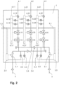
- 2 12 schematically shows a mixing center 1 according to the invention.
- mixing lines 4.1, 4.2, 4.3 are provided, which are routed to the decentralized loads.
- any number of mixing lines 4.1, 4.2, 4.3 can be provided, preferably between three and eight.
- the hot water line 2 is routed via a pressure reducing valve 2.1 to the hot water distributor 2.4. Accordingly, the cold water line 3 is routed via a pressure reducing valve 3.1 to the cold water distributor 3.4. Temperature sensors 2.2, 3.2 and pressure sensors 2.3, 3.3 are attached to the hot water distributor 2 and the cold water distributor 3, with which the temperature and the pressure of the water conveyed in these distributors is measured.
- the temperature mixers 4.16, 4.26, 4.36 are connected to the hot water distributor 2.4 and the cold water distributor 3.4 in accordance with the number of mixing lines 4.1, 4.2, 4.3.
- the temperature mixers 4.16, 4.26, 4.36 mix hot water and cold water in an adjustable ratio, whereby water of a certain temperature is guided to the outlet.
- a corresponding number of flow regulators 4.15, 4.25, 4.35 are connected, with which the volume flow, respectively.
- the pressure of the water flow delivered at the outlet of the temperature mixers 4.16, 4.26, 4.36 can be adjusted.
- the output of the volume regulators 4.15, 4.25, 4.35 is led to the mixing lines 4.1, 4.2, 4.3, with temperature sensors 4.14, 4.24, 4.34, pressure sensors 4.13, 4.23, 4.33 and flow sensors 4.12, 4.22, 4.23 in between are arranged, with which the pressure, the temperature and the flow rate of the guided water in these lines is measured.
- a mixing electronics 4.17, 4.27, 4.37 is assigned to each mixing line 4.1, 4.2, 4.3.
- the hot water line 2 is assigned to the hot water electronics 2.5 and the cold water line 3 to the cold water electronics 3.5.
- Each electronic mixing device 4.17, 4.27, 4.37 is equipped with the corresponding temperature mixer 4.16, 4.26, 4.36, quantity regulator 4.15, 4.25, 4.35, temperature sensor 4.14, 4.24, 4.34, pressure sensor 4.13, 4.23, 4.33 and flow sensor 4.12, 4 .22, 4.23 connected in terms of signal.
- Each mixer electronics 4.17, 4.27, 4.37 is also connected in terms of signals via electrical connections 4.11, 4.21, 4.31 to the operating devices 10.1, 10.2, 10.3 assigned to the respective mixer lines 4.1, 4.2, 4.3.
- Each mixing electronics 4.17, 4.27, 4.37 is set up to receive parameter values entered on the corresponding operating device 10.1, 10.2, 10.3 and/or to send measured values to the operating device 10.1, 10.2, 10.3. Furthermore, each mixing electronics 4.17, 4.27, 4.37 is set up to control the settings of the respective temperature mixers 4.16, 4.26, 4.36 and volume controllers 4.15, 4.25, 4.35 on the basis of received parameter values and measured values. Parameter values can thus be set on the operating devices 10.1, 10.2, 10.3 and a corresponding water flow can be made available on the mixing lines 4.1, 4.2, 4.3, i. H. e.g. B. a water flow of a desired temperature, pressure, flow rate, quantity or any other desired parameter.
- the mixing electronics 4.17, 4.27, 4.37, the hot water electronics 2.5 and the cold water electronics 3.5 are connected to one another in terms of signals via a bus system 9.1.
- the bus system 9.1 is connected to the control center 9 in terms of signals.
- the settings of the pressure reducing valves 2.1, 3.1 can also be changed or the measured values of the temperature sensors 2.2, 3.2 and/or pressure sensors 2.3 attached to the hot water distributor 2 and/or the cold water distributor 3 , 3.3 into account.
- the valves 2.1, 3.1 be opened in addition to allow a simultaneous high water demand of the mixing lines 4.1, 4.2, 4.3.
- the invention can be used instead of water for any other fluid such.
- B. be applied to an oil, gasoline, a gas or any other fluid.
- the operating devices 10.1, 10.2, 10.3 can be connected in terms of signals to the control center 9 instead of to the mixing center 1.
- the mixing center 1 can include the control center 9 so that the corresponding inputs, outputs or signal connections are arranged on the mixing device 1 .
- the transmission of signals can be based on transmission cables and/or wired bus systems, which are installed between the individual components such as the control center 9, the sensors, the operating devices, etc.
- wireless signal connections can be provided instead or in addition, for example, in particular according to a WiFi standard.
- a system according to the invention enables the desired operating states and supports the required scenarios for a wide variety of consumers. The consumer is identified and the relevant parameters are managed centrally.
- the temperature mixer is therefore set to cold water.
- the volume regulator is opened and the water flows into the toilet bowl.
- the water requirement can be programmed for different situations.
- the flow sensors can be used to determine exactly how much water should reach the toilet bowl.
- the system pressure for flushing the toilet can also be increased for a short time without changing the volume of water needed for flushing. Immediate rinsing, if necessary, is also possible since there is no reservoir that has to be refilled first.
- the toilet bowl is directly connected to the mixed water line. Also a supply of the toilet with hot water is possible by letting the temperature mixer run on hot water. This could be an advantage when cleaning the toilet, for example.
- the hot water supply from the toilet can also be activated for other applications (shower-toilet, etc.).
- the amount of water is less important than the length of time someone spends in the shower. Therefore, less water pressure is used here.
- a desired temperature can therefore be set and also saved by the user, which is considered the comfort temperature. It is also possible to set a maximum temperature to ensure that nobody is scalded by water that is too hot.
- a precise amount of water is required.
- the flow sensor controls the water flow and adjusts the desired amount of water. So it is possible, for example, z. B. retrieve 0.75 liters of water or any other predetermined amount of water without the use of a measuring cup is necessary. Such amounts of water can also be saved individually or together as a combination of water amount and water temperature. It is also possible to fill a pan by turning the faucet resp. holds the pull-out spray over a pan and a proximity sensor then sends the command to switch off to the system as soon as the water level has approached the desired distance from the sensor.
- the volume preselection and the temperature are of great importance. This makes it possible to save and retrieve different filling quantities for individual people and their comfort temperature.
- the pressure reducing valve can also be automatically and temporarily set to a higher pressure.
- a dishwasher generally only has one connection, which is mostly used for cold water, but would often also be suitable for hot water. Since it depends on the machine whether or not it is allowed to be connected to the hot water line, replacing it with a different machine type often involves adapting the sanitary installation (pulling additional lines). For this reason, new dishwashers are often only connected to the cold water connection, which does not make sense in terms of energy. Thanks to the mixed water line concept, both machine types can be connected to our system. It is therefore possible to only use cold, warm or mixed water. There is also the possibility of passing on direct instructions (amount of water and temperature) from the dishwashers to the system according to the invention via an open communication interface and thus obtaining the amount of water and the water temperature specifically and optimized for the current wash cycle.
- the water consumption can be monitored individually with the flow sensors.
- the control center can be set up, for example, to indicate high water consumption in the case of operating devices and to display proposed solutions for reducing water consumption. Water consumption can also be easily recorded for billing purposes.
- the system according to the invention identifies the individual consumers and makes it possible to predefine the pressure for the individual consumers and thus create opportunities for saving water. Another advantage is that if there are several active consumers which lead to a reduced pressure, the pressure can be increased by opening the pressure reducing valves further. If water is required by several consumers, more pressure can be made available without a noticeable reduction in the liter output or the temperature level.
- the pressure for the individual applications can be set through the clear identification of the consumers. if e.g. B. a bathtub is activated, the entire power can be passed on via the pressure reducing valves, so that the bathtub can be filled in the shortest possible time. However, if another consumer such. B. When a shower or washbasin tap is activated, the pressure reducing valves reduce the pressure so that water is not used unnecessarily.
- the pressure sensor in the mixed water line can be used to measure the flow pressure when water is drawn off. These values are logged and evaluated. This evaluation (increase in pressure) makes it possible to identify constrictions in the line, e.g. B. by I ⁇ alk to be recognized early before damage can occur.
- the pressure sensors can be used to determine whether the system has a leak. If these sensors register a drop in pressure although no consumer is activated, then it can be concluded that there is a leak.
- the pressure reducing valves are closed and thus the system is separated from the main water line. This will perform an emergency shutdown and minimize damage from a leak.
- the pressure in the house installation can be monitored by the pressure sensors on the hot water distributor and cold water distributor. If this pressure now drops and no consumers are active at the same time, a leak is suspected. In this case, the protective valve is closed directly at the central supply line from the building so that no water can flow out of the supply line. In order to further reduce the damage, all useful consumers are activated in a controlled manner and the water is drained into the sinks, bathtubs, etc. This intentional reduction in pressure in the system greatly reduces the amount of water flowing out at the leak point.
- the system automatically activates the consumers if they z. B. were not active for a long time. It can happen that after a longer absence, e.g. B. holidays, the water barrier in the siphon evaporates. This means that the odor from the sewage pipes can penetrate into the rooms. To prevent this, the system can intervene in a targeted manner and eject a small amount of water around this water barrier to be constantly maintained. According to the invention, an increase in legionella can be prevented by flushing the system itself from time to time and thus preventing an increase in the number of legionella.
- the invention results in advantages for various consumers, in particular due to the optimized mixing ratios between old and hot water, due to the achievement of high temperature accuracy and flow rate accuracy and the economical use of water as a resource.
- Figures 3 and 4 show details of a further exemplary embodiment of a sanitary system according to the invention, which includes recovery to reduce water consumption and to increase the energy efficiency of the sanitary system. It should be mentioned that the recovery can be used independently of the invention according to claim 1.
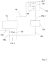
- FIG 3 a mixing center 1b of this further embodiment of a sanitary system according to the invention is shown.
- This mixing center 1b is connected to the rest of the sanitary system (not shown in detail) via an old water pipe 3b and a hot water circulation pipe 15b.
- I ⁇ old water is supplied to the mixing center 1b via the I ⁇ old water line 3b.
- Hot water is supplied to the mixing center via the hot water circulation line 15b.
- a mixing line 4b leads from the mixing center 1b to a switchover 11b, in which a decentralized consumer 5b (here a shower), a 3/2-way valve 12b and a temperature sensor 4b.1 are arranged.
- a return line 14b leads from the changeover 11b first to a return collection point 13b and then to a confluence point with the hot water circulation line 15b.
- a circulation pump 16b arranged, which allows the hot water to circulate in the hot water circulation line 15b.
- figure 3 also shows three backflow preventers 17b.1, 17b.2 and 17b.3. These backflow preventers 17b.1, 17b.2 and 17b.3 prevent water from flowing back from the return collection 13b in the direction of the changeover 11b, or from water flowing back from the hot water circulation line 15b into the return line 14b, or from flowing back Water from an outlet of the circulation pump 16b through an inlet of the circulation pump 16b.
- the non-return valves can be known one-way or non-return valves.
- the backflow preventer 17b.3 can also be integrated in the circulation pump 16b.
- the recovery function is as follows: if a user wants to use the decentralized consumer 5b to take a shower, he can first preselect a desired shower water temperature and then start the shower process. From the beginning of the shower process, the temperature sensor 4b.1 can determine the temperature of the mixed water, which reaches the changeover 11b via the mixing line 4b, and, if necessary, via an in figure 3 BUS system, not shown, to different components of the sanitary system, for example to the mixing center 1b. As long as the temperature of the water from the mixing line 4b does not yet correspond to the desired shower water temperature, the 3/2-way valve does not direct the water from the mixing line 4b to the decentralized consumer 5b (here the shower), but directly into the return line 14b. The return line 14b directs this not yet correctly heated return water to the hot water circulation line 15b.
- This boiler is fed not only with cold water, but rather with a mixture of cold water and the (return) water of the hot water circulation line 15b.
- the sanitary system requires less water than a sanitary system without recovery and also comparatively little energy, since the water that is fed to the boiler is a mixture of cold water and return or circulation water, which has a higher temperature than simple cold water has.
- another non-return valve can be arranged between the hot water circulation line 15b and the cold water line 3b (in figure 3 Not shown).
- Switching 11b is in figure 3 shown in their return position. This position is active when a user requests shower water at the desired shower water temperature, but this is not yet available at the decentralized consumer 5b. In this case, the mixed water that is not yet at the right temperature is fed back into the hot water circulation line 15b via the return line 14b, which leads back to the boiler.
- the switch 11b is shown in its consumption position. This position is active when shower water is available at the desired shower water temperature. In this case, the mixed water at the correct temperature is routed from the mixing line 4b directly to the decentralized consumer 5b - in this case to the shower fitting.
Landscapes
- Engineering & Computer Science (AREA)
- Health & Medical Sciences (AREA)
- Life Sciences & Earth Sciences (AREA)
- Hydrology & Water Resources (AREA)
- Public Health (AREA)
- Water Supply & Treatment (AREA)
- Physics & Mathematics (AREA)
- General Physics & Mathematics (AREA)
- Automation & Control Theory (AREA)
- Domestic Plumbing Installations (AREA)
- Domestic Hot-Water Supply Systems And Details Of Heating Systems (AREA)
Description
- Die Erfindung betrifft ein Sanitärsystem mit einer Mischzentrale gemäß dem Oberbegriff von Anspruch 1, wie es aus der Druckschrift
WO85/03764 - Sanitäre Systeme in Häusern und Wohnungen stellen Brauchwasser insbesondere für Waschbecken, Badewannen, Duschen, WCs, Waschmaschinen, Küchenspüle oder Geschirrspüler zur Verfügung. Wo erforderlich, werden eine Warmwasserleitung und eine Kaltwasserleitung zum Verbraucher verlegt und beim Verbraucher Mischvorrichtungen installiert, um Brauchwasser einer bestimmten Temperatur und einer bestimmten Durchflussgeschwindigkeit zu beziehen, also insbesondere bei Waschbecken, Badewannen, Duschen und Küchenspülen. Falls nur eine Kaltwasserversorgung erforderlich ist, also insbesondere bei WCs, Waschmaschinen oder Geschirrspüler, wird nur eine Kaltwasserleitung zum Verbraucher verlegt.
- Die
CH 698 596 - Die
EP 0 195 271 zeigt eine Sanitäreinrichtung, um in einem Badezimmer mehrere Wascheinrichtungen mit heissem und kaltem Wasser zu versorgen. Eine Zentrale umfasst einen Kalt- und Warmwasseranschluss und mehrere Auslässe zur Versorgung der Wascheinrichtungen mit Wasser. Temperatur und Menge werden für jeden Auslass durch ein Mischventil eingestellt. Eine thermoskopische Einheit hält die Temperatur im Wesentlichen auf dem vorgegebenen Wert. Ein Temperatursensor ist mit einer Steuereinheit verbunden. Einstellvorrichtungen und eine Hauptsteuerung sind mit der Zentrale verbunden. Die Zentrale kann für jede einzelne an der Steuerung angehängte Armatur einen Durchfluss- oder Druckregler für die individuelle Regelung aufweisen. Alle Funktionen (Volumen, Temperatur, Fluss) werden durch die zentrale Steuereinheit kontrolliert, wobei der Benutzer aber nach wie vor Temperatur und Ein/Aus-Zustand verändern kann. Durch den programmgesteuerten automatisierten Betrieb des Steuersystems können gewisse Sicherheitsaspekte berücksichtigt werden. - Die
DE 101 19 690 betrifft eine Sanitärinstallation in einem Bad. Das Bad weist mehrere, räumlich auseinander liegende Sanitäreinrichtungen wie eine Badewanne, eine Dusche, ein Handwaschbecken, ein Bidet und dergleichen auf. Eine zentrale Mischarmatur weist eingangsseitige Anschlüsse für Kalt- und Warmwasser und mehrere Mischwasserauslässe auf. Die Mischwasserauslässe sind mit jeweils einem Wasserzulauf einer Sanitäreinrichtung verbunden. Die Sanitäreinrichtung umfasst eine Temperaturmesseinrichtung und eine Durchflussmesseinrichtung. Eine elektronische Steuerung steuert und überwacht alle Mischwasserströme. Es können Vorgabewerte für die Mischwassertemperatur oder Durchflussmenge eingegeben und abgespeichert werden. Ein Ein-/Ausgabegerät umfasst Tasten sowie ein Display und kann dezentral an Sanitäreinrichtungen angeordnet sein. - Die
WO 03/107527 - Gebräuchliche sanitäre Systeme benötigen einen hohen Installationsaufwand. Bestehende Installationen lassen sich nur aufwendig an unterschiedliche Bedürfnisse oder Vorgaben anpassen.
- Aufgabe der Erfindung ist es, ein dem eingangs genannten technischen Gebiet zugehörendes sanitäres System zu schaffen, welches einen geringen Installationsaufwand erfordert und flexible Anpassungen an unterschiedliche Anforderungen ermöglicht.
- Die Lösung der Aufgabe ist durch die Merkmale des Anspruchs 1 definiert. Gemäss der Erfindung ist eine den Verbraucher betreffende Verbraucheridentifikation an die Steuerzentrale übertragbar, welche die Steuerzentrale zur Steuerung der steuerbaren Mischeinheit berücksichtigt.
- Die Übertragung der Verbraucheridentifikation erfolgt über irgendeinen I<ommunikationskanal, d. h. über ein I<ommunikationskabel wie eine Signalleitung, über ein Bussystem, über eine drahtlose I<ommunikationsverbindung wie z. B. ein WiFi-Netzwerk oder über irgendeinen anderen I<ommunikationskanal. Gemäss der Erfindung ist beim Verbraucher ein elektronischer Speicher vorgesehen zur Abspeicherung der Verbraucheridentifikation, also z. B. ein Mikroprozessor mit einem digitalen Speicher, sowie ein I<ommunikationsmodul wie beispielsweise ein serielles Interface. Die Steuerzentrale weist ein entsprechendes I<ommunikationsmodul auf, das mit dem beim Verbraucher angebrachten I<ommunikationsmodul verbunden ist, also z. B. über ein serielles I<ommunikationskabel. Nach der Einstellung eines Parameterwerts an der Bedieneinrichtung wird dieser an die Steuerzentrale übertragen, welche sogleich über die erwähnten I<ommunikationsmittel eine Abfrage betreffend die Verbraucheridentifikation durchführt. Eine Verbraucheridentifikation kann auch z. B. an der Bedieneinrichtung eingegeben und über eine I<ommunikationsverbindung von der Bedieneinrichtung an die Steuerzentrale übertragen oder übermittelt werden. Eine Verbraucheridentifikation kann ferner auch direkt bei der Steuerzentrale eingegeben werden, beispielsweise über eine Tastatur, welche an die Steuerzentrale bei Inbetriebnahme des Sanitärsystems angeschlossen wird, um eine I<onfiguration des Systems durchzuführen.
- Gemäss der Erfindung ist in einem Datenspeicher der Steuerzentrale eine Liste von möglichen bzw. zulässigen Verbrauchern abgespeichert. Mit Hilfe der übermittelten Verbraucheridentifikation kann die Steuerzentrale die Ventile bzw. Mischer steuern, die zur Fluidleitung gehören, an welcher der Verbraucher angeschlossen ist.
- Es sind ferner Mittel vorgesehen, um die Verbraucheridentifikation mit einer Mischleitung zu verknüpfen. Bei einer kabelgebundenen oder bussystemgebundenen Übertragung der Verbraucheridentifikation ergibt sich die Identifikation der Mischleitung durch die Identifikation des betreffenden I<abels oder des betreffenden Busteilnehmers. Bei einer funkbasierten Übertragung der Verbraucheridentifikation kann an der Mischleitung verbraucherseitig eine Identifikation angebracht sein, welche zusammen mit der Verbraucheridentifikation übertragen wird. Die an der Mischleitung verbraucherseitig angebrachte Identifikation kann visuell oder elektronisch erfassbar sein, also z. B. aus einem Nummernschild oder einem elektronischen Speichermittel wie einem RFID-Chip bestehen.
- Durch die Berücksichtigung der Verbraucheridentifikation zur Steuerung der steuerbaren Mischeinheit wird insbesondere gewährleistet, dass beim Verbraucher kein Schaden angerichtet wird. Die Steuerzentrale ist beispielsweise eingerichtet, dass aus der Verbraucheridentifikation der Verbrauchertyp ermittelbar ist, also dass feststellbar ist, ob es sich um eine Dusche, ein Waschbecken, eine Badewanne oder ein WC handelt. Bei einer Dusche kann die maximale Temperatur des Wassers begrenzbar sein, um Verbrühungen des Benutzers zu vermeiden. Bei einem Waschbecken kann der Wasserdruck begrenzbar sein, um ein Verspritzen von Wasser, welches mit zu hohem Druck auf das Waschbecken trifft, zu verhindern.
- Die Mischzentrale weist ausgangseitig mehrere Mischleitungen auf und ist eingerichtet, um beispielsweise alle sanitären Einrichtungen eines Badezimmers oder einer Küche mit Wasser zu versorgen. So kann eine Mischleitung für das Waschbecken, eine Mischleitung für die Dusche, eine Mischleitung für die Badewanne und eine Mischleitung für das WC vorgesehen sein. Die Mischzentrale kann direkt in einem Zimmer, also z. B. im Badezimmer, angeordnet sein. Es ist aber auch möglich, die Mischzentrale z. B. im I<eller oder einem anderen Nebenraum anzubringen.
- Eine Mischeinheit kann einen Temperaturmischer und einen Mengenregler aufweisen. Der Temperaturmischer ist eingangsseitig mit der Warmwasserleitung und der I<altwasserleitung verbunden und stellt ausgangsseitig ein bestimmtes Mischverhältnis zwischen Warmwasser und I<altwasser zur Verfügung. Mit dem Mengenregler wird anschliessend die Wassermenge eingestellt, welche an die Mischleitung abgegeben wird. Die Mischeinheit kann aber auch Dosiereinrichtungen für das Warmwasser und das I<altwasser aufweisen, wobei eine dosierte Warmwassermenge und Kaltwassermenge zusammengeführt und an die Mischleitung abgegeben wird (wie z. B. in der
CH 698 596 - Verbraucher betreffen sanitäre Einrichtungen mit oder ohne einer Armatur, also beispielsweise Waschbecken, Spültröge, Badewannen, Duschen oder WCs, Geschirrspüler, Waschmaschinen.
- Die Verbraucheridentifikation kann regelmässig, zu bestimmten Zeitpunkten oder aufgrund bestimmter Ereignisse an die Steuerzentrale übermittelt werden. So kann beispielsweise bei einer Geschirrspülmaschine oder bei einer Waschmaschine die Verbraucheridentifikation regelmässig abgefragt werden, um die aktuell notwendigen Brauchwassereinstellungen betreffend Temperatur oder Druck einzustellen. Dabei ist die Verbraucheridentifikation nicht gleichzusetzen mit einem Steuerbefehl, welcher der Steuerzentrale z. B. angibt, welche Menge an Wasser, welcher Druck, welche Temperatur etc. zu einem bestimmten Zeitpunkt an den Verbraucher abzugeben ist. Die Verbraucheridentifikation kann auch im Rahmen eines Waschprogramms zusammen mit den Verbraucherbefehlen (welche Temperatur, Menge, Druck etc. spezifizieren) an die Steuerzentrale übermittelt werden, um erforderliche Einstellungen des Brauchwassers anzufordern. Statt einer regelmässigen Abfrage der Verbraucheridentifikation können Parameter betreffend notwendige Brauchwassereinstellungen separat übermittelt oder abgefragt werden.
- Da zwischen der Mischzentrale und dem Verbraucher nur eine einzelne Mischwasserleitung installiert werden muss, wird der Installationsaufwand grundsätzlich verkleinert. Aus der Verbraucheridentifikation lassen sich für den Verbraucher angepasste Betriebswerte automatisch und ohne zusätzliche Installationen einstellen. Dadurch wird der Installationsaufwand bei der Erstinstallation und auch der Unterhaltsaufwand bei einem Wechsel von Verbrauchern vereinfacht.
- Vorzugsweise sind Sensoren vorgesehen zur Bestimmung von Messwerten wie insbesondere der Temperatur, des Drucks und/oder der Durchflussmenge, welche die Steuerzentrale zur Steuerung und/oder Regelung der steuerbaren Mischeinheit berücksichtigt. Die Sensoren sind beispielsweise ausgangsseitig an den Mischleitungen angeordnet. Sensoren können auch eingangsseitig an der Warmwasserleitung und/oder an der I<altwasserleitung angeordnet sein. Die Steuerzentrale kann eingerichtet sein, um die steuerbare Mischeinheit entweder nur zu steuern, d. h. ein bestimmtes Mischverhältnis und einen bestimmte Durchflussmenge oder einen Druck einzustellen. Die Steuerzentrale kann aber auch eingerichtet sein, die Messwerte der Sensoren zu berücksichtigen, um bei einer Abweichung der Temperatur oder des Drucks die steuerbare Mischeinheit entsprechend zu regeln. Die von den Sensoren ermittelten Messwerte können an die Bedieneinrichtung übertragen werden, um diese dem Benutzer anzuzeigen.
- In einer bevorzugten Ausführungsform weist der Verbraucher eine aufsteckbare Armatur mit einer an die Steuerzentrale übertragbaren Verbraucheridentifikation auf. Die aufsteckbare Armatur stellt beim Aufstecken zugleich eine Wasserverbindung als auch elektrische Verbindungen her, also eine elektrische Signalverbindung und/oder eine Verbindung zur elektrischen Energieübertragung. Eine solche Verbindung ist z. B. aus der
US 6,006,784 bekannt. Insbesondere kann die aufsteckbare Armatur so ausgeführt sein, wie in der gleichzeitig mit der vorliegenden Anmeldung eingereichten Anmeldung "Armatursockel und aufsteckbare Armatur" des gleichen Anmelders beschrieben. Die Armatur kann beispielsweise eingerichtet sein, dass zunächst die Wasserverbindung erstellt wird und erst anschliessend elektrische Verbindungen. Dadurch kann gewährleistet werden, dass eine Wasserabgabe erst bei erstellter Wasserverbindung erfolgt. Die Steuerzentrale und/oder die Armatur können eingerichtet sein, dass die Verbraucheridentifikation an die Steuerzentrale übertragen wird, sobald die elektrische Verbindung bei der Armatur erstellt ist. - Alternativ wird bei einem Verbraucher ohne aufsteckbare Armatur, also z. B. bei einem WC, einer Spülmaschine oder einer Waschmaschine die Verbraucheridentifikation beispielsweise direkt, d. h. über eine an die Steuerzentrale angeschlossene Tastatur oder über eine Schnittstelle zu einem portablen Computer bei der Steuerzentrale eingegeben.
- Vorzugsweise ist eine Verbraucheridentifikation mit der Bedieneinrichtung generierbar und an die Steuerzentrale übertragbar. Dies ist insbesondere von Vorteil bei Verbrauchern ohne abgespeicherte Verbraucheridentifikation, wie dies beispielsweise bei einem WC der Fall sein kann. Die Eingabe der Verbraucheridentifikation kann über irgendwelche an der Bedieneinrichtung vorgesehenen Eingabemittel erfolgen, also beispielsweise über eine Tastatur, einen Touchscreen, eine Leseeinrichtung wie einen optischen Scanner, ein RFID-Lesegerät, oder irgendwelche andere Eingabemittel.
- Bevorzugt sind zur Signal- und/oder Energieübertragung kabelbasierte, bussystembasierte und/oder funkbasierte Verbindungen vorgesehen. Kabelbasierte oder bussystembasierte Verbindungen erfordern einen zusätzlichen Installationsaufwand, ermöglichen aber eine Energieübertragung und können eine hohe Betriebssicherheit bieten. Demgegenüber erfordern funkbasierte Verbindungen wie z. B. in einem WiFi-Drahtlosfunknetzwerk einen kleineren Installationsaufwand. Zur Bereitstellung von elektrischer Energie sind jedoch Batterien erforderlich oder zusätzliche I<abelverbindungen. Eine funkbasierte Verbindung ist tendenziell störanfälliger als eine kabelbasierte Lösung. Eine kabelbasierte Verbindung wird auch als drahtgebundene Verbindung bezeichnet.
- Vorzugsweise berücksichtigt die Steuerzentrale aufgrund einer Auswertung einer Verbraucheridentifikation einen Maximal- und/oder Minimalwert, beispielsweise eine maximale Wassertemperatur, eine maximale Wassermenge und/oder einen minimalen Wasserdruck. Dadurch lassen sich insbesondere Verbrühungen bei Benutzern wegen zu heissem Wasser, ein Verspritzen von Wasser wegen zu hohem Wasserdruck, ein Überlaufen einer Badewanne wegen einer zu grossen Wassermenge oder irgendwelche andere Schäden verhindern. Die Auswertung der Verbraucheridentifikation kann sich beispielsweise auf eine Tabellen- und/oder Datenbankabfrage beziehen.
- Gemäss der Erfindung weist die Steuerzentrale eine Tabelle auf zur Zuordnung von Verbraucheridentifikationen zu zulässigen Betriebswerten eines Verbrauchers. Aufgrund der Tabelle lässt sich eine Zuordnung schnell und effizient durchführen. Die Tabelle kann für denselben Verbrauchertyp verschiedene Einträge aufweisen, so dass beispielsweise für eine aufsteckbare Armatur mit einem Auslass, der vom Waschbecken weit entfernt ist, ein anderer Betriebswert wie beispielsweise ein Wasserdruck einstellbar ist als für eine aufsteckbare Armatur mit einem Auslass, der sehr nahe am Waschbecken ist.
- Die Mischzentrale weist mehrere Mischeinheiten auf, vorzugsweise zwischen drei und acht Mischeinheiten, welche in modularer Bauweise anordenbar sind. Mit einer solchen Mischzentrale können typische sanitäre Installationseinheiten wie ein Badezimmer, eine Küche, ein WC vollständig mit Brauchwasser versorgt werden. Es kann ein Modul vorgesehen sein zum Anschluss an die Warm- und Kaltwasserleitung, an welchem eine gewünschte Anzahl identischer Module mit je einer Mischeinheit angeschlossen werden I<önnen, d. h. ein erstes Modul erstellt die Verbindung zur Warm- und Kaltwasserleitung und daran werden quasi in serieller Weise ein zweites, drittes usw. Modul mit je einer Mischeinheit angeschlossen.
- Bevorzugt weist eine Mischeinheit einen Temperaturmischer zur Erstellung eines Mischverhältnisses von Warm- und Kaltwasser sowie einen daran angeschlossenen Mengenregler auf. Die Erstellung der Temperatur des Brauchwassers und die Einstellung des Drucks, der Menge oder Fliessgeschwindigkeit erfolgt durch zwei auf die jeweilige Aufgabe optimierte Vorrichtungen und ist dementsprechend präzise und einfach steuerbar. Alternativ weist die Mischeinheit je eine Dosiereinrichtung für das Warm- und das Kaltwasser auf. Die Einstellung von Wassertemperatur und/oder -druck kann sich dadurch jedoch komplizierter gestalten.
- Vorzugsweise ist anschliessend an eine Mischeinheit ein Temperatursensor, ein Drucksensor und/oder ein Durchflusssensor vorgesehen. Die Messwerte der Sensoren werden an die Steuerzentrale übermittelt und es wird dadurch eine sehr präzise Regelung von Parametern wie Wassertemperatur oder -druck ermöglicht.
- In einer bevorzugten Ausführungsform ist ein Druckreduzierventil für die Warmwasserleitung und/oder ein Druckreduzierventil für die Kaltwasserleitung vorgesehen. Je nach Auslastung der Mischzentrale kann somit ein entsprechender Warm- und/oder Kaltwasserdruck zur Verfügung gestellt werden. So kann ein kurzzeitig erhöhter Druckbedarf, wie bei einer WC-Spülung oder bei der Reinigung einer Dusche, befriedigt werden. Falls die Mischzentrale sehr viele Mischleitungen aufweist, welche gleichzeitig benutzt werden, kann der entsprechende Wasserbedarf durch ein Öffnen der Druckreduzierventile bereitgestellt werden.
- Bevorzugt ist für die Warmwasserleitung und/oder für die Kaltwasserleitung ein Temperatursensor, ein Drucksensor und/oder ein Durchflusssensor vorgesehen. Die Messwerte dieser Sensoren können an die Steuerzentrale übermittelt werden und für die Einstellung der Mischeinheiten berücksichtigt werden. Falls beispielsweise das zugeführte Warmwasser an Temperatur verliert, kann die Mischeinheit schnell und präzis nachgeregelt werden.
- In Ergänzung der obigen Erfindung kann ein Sanitärsystem vorgesehen sein, welches eine Rückgewinnung zum Rückgewinnen von Wasser und/oder Wärmeenergie umfasst. Die Rückgewinnung wird im Wesentlichen mit Hilfe von Wasserleitungen und Ventilen gebildet, wobei die Ventile vorzugsweise durch eine Steuerschaltung und einen Motor betätigbar sind. Mit Hilfe einer solchen Rückgewinnung ist es typischerweise möglich, beispielsweise zu Beginn eines Duschvorgangs noch nicht wunschgemäss temperiertes Wasser über eine Rücklaufleitung wieder einer Warmwasserzirkulationsleitung zuzuführen, insbesondere ohne dass das Wasser das Sanitärsystem verlässt. Dies hat zum einen den Vorteil, dass Wasser gespart wird, und zum anderen, dass die Wärmeenergie des in der Rücklaufleitung zurücklaufenden Wassers genutzt werden kann. Auf diese Weise ist es typischerweise möglich, den Wasser- und Energieverbrauch des Sanitärsystems zu senken. Dabei ist zu beachten, dass die Rückgewinnung auch auf andere (flüssige oder gasförmige) Medien anstelle von Wasser anwendbar ist.
- Die Rückgewinnung umfasst ein 3/2 Weg-Ventil. Das 3/2 Weg-Ventil ist vorzugsweise eingangsseitig mit einer Mischleitung des Sanitärsystems verbunden, über die dem 3/2 Weg-Ventil temperiertes Mischwasser zugeleitet wird. Typischerweise ist das 3/2 Weg-Ventil ausgangsseitig mit einem Verbraucher, beispielsweise einer Duschbrause, einem Wasserhahn oder ähnlichem, und mit der Rücklaufleitung verbunden. Das 3/2 Weg-Ventil ist typischerweise geeignet, in Abhängigkeit der Temperatur des eingangsseitig zugeleiteten temperierten Mischwassers das temperierte Mischwasser entweder dem Verbraucher oder aber der Rücklaufleitung zuzuleiten.
- Bei vorteilhaften Ausführungsformen umfasst die Rückgewinnung eine Rücklaufsammlung. Eine solche Rücklaufsammlung ist vorteilhafterweise geeignet, mehrere Rücklaufleitungen zusammenzufassen bzw. rücklaufendes Wasser aus mehreren Rücklaufleitungen zu sammeln und das so gesammelte Wasser dann bevorzugt kontrolliert der Warmwasserzirkulationsleitung zuzuführen. Eine solche Rücklaufsammlung hat den Vorteil, dass eine Gesamtleitungslänge in dem Sanitärsystem reduziert werden kann.
- Besonders vorteilhaft ist es, wenn die Rückgewinnung einen Temperatursensor zur Steuerung des 3/2 Weg-Ventils umfasst. Vorteilhafterweise umfasst der Temperatursensor eine BUS-Verbindung zum Verbinden des Temperatursensors mit einem BUS des Sanitärsystems. Der Temperatursensor ist typischerweise eingangsseitig am 3/2 Weg-Ventil angeordnet. Diese Konfiguration hat den Vorteil, dass eine besonders genaue Steuerung des 3/2 Weg-Ventils ermöglicht wird, und dass eine Information des Temperatursensors über die BUS-Verbindung an unterschiedlichen Stellen des Sanitärsystems einfach und im Wesentlichen in Echtzeit abrufbar und/oder verarbeitbar ist.
- Aus der nachfolgenden Detailbeschreibung und der Gesamtheit der Patentansprüche ergeben sich weitere vorteilhafte Ausführungsformen und Merkmalskombinationen der Erfindung.
- Die zur Erläuterung des Ausführungsbeispiels verwendeten Zeichnungen zeigen:
- Fig. 1
- ein erfindungsgemässes Sanitärsystem;
- Fig. 2
- eine erfindungsgemässe Mischzentrale;
- Fig. 3
- ein Ausschnitt aus einem erfindungsgemässen Sanitärsystem mit Rückgewinnung; und
- Fig.4
- ein Ausschnitt aus einer erfindungsgemässen Rückgewinnung mit Umschaltung.
- Grundsätzlich sind in den Figuren gleiche Teile mit gleichen Bezugszeichen versehen.
-
Fig. 1 zeigt schematisch ein erfindungsgemässes Sanitärsystem. Eine Mischzentrale 1 ist eingangsseitig an eine Warmwasserleitung 2 und an eine Kaltwasserleitung 3 angeschlossen. Typischerweise ist die Mischzentrale 1 einem Sanitärraum wie einem WC-Raum, einem Duschraum, einem Badezimmer, einer Küche, einem Waschmaschinenraum oder irgendeinem anderen Sanitärraum zugeordnet. Die Mischzentrale 1 kann aber auch einer Wohnung, einem Stockwerk oder irgendeinem anderen Hausbereich zugeordnet sein. - Die Mischzentrale 1 weist mehrere Mischleitungen 4.1, 4.2, 4.3 auf, deren Anzahl je nach Bedarf typischerweise zwischen drei bis acht liegt. Es können aber beliebig viele Mischleitungen 4.1, 4.2, 4.3 vorgesehen sein.
- Die Mischleitungen 4.1, 4.2, 4.3 sind eingerichtet, um Wasser den dezentralen Verbrauchern 5.1, 5.2, 5.3 zuzuführen. Die dezentralen Verbraucher 5.1, 5.2, 5.3 können eine Armatur eines Waschbeckens, einer Badewanne, einer Dusche, ein WC, eine Geschirrspülmaschine, eine Waschmaschine, oder irgendeinen anderen sanitären Verbraucher betreffen. In
Fig. 1 ist mit dem Bezugszeichen 5.1 ein Lavabo, mit dem Bezugszeichen 5.2 eine Badewanne und mit dem Bezugszeichen 5.3 ein WC schematisch skizziert. - Die Mischleitungen 4.1, 4.2, 4.3 führen, wie nachfolgend noch erklärt wird, Wasser gemäss gewünschten Parametern wie insbesondere einer bestimmten Temperatur, einem bestimmtem Druck, einer bestimmten Durchflussmenge oder irgendeinem anderen Parameter.
- Auf der Eingangsseite der Mischvorrichtung 1 ist ein Boiler 6 zur Erzeugung von Warmwasser vorgesehen, welcher eingangsseitig an die Kaltwasserleitung 3 angeschlossen ist und ausgangseitig Wasser einer bestimmten Temperatur zur Mischvorrichtung 1 führt. Es sind Ventile 7.1, 7.2 vorgesehen, um die Zufuhr von Kaltwasser von der Versorgungsleitung 8 zum Boiler 6 sowie zur Kaltwasserleitung 3 und die Zufuhr von Warmwasser zur Warmwasserleitung 2 einzustellen.
- An die Ventile 7.1, 7.2 anschliessend sind Drucksensoren 7.11, 7.12, Temperatursensoren 7.21, 7.22 und Durchflusssensoren 7.13, 7.23 angeordnet, mit welchen die Temperatur, der Druck und die Durchflussmenge gemessen werden können.
- Das erfindungsgemässe sanitäre System umfasst ferner eine Steuerzentrale 9, welche beispielsweise einen Mikroprozessor mit darauf ablauffähigen Softwaremodulen umfasst. Die Steuerzentrale 9 weist Eingänge für die Signale von Sensoren auf, wie z. B. für die Drucksensoren 7.11, 7.12, die Temperatursensoren 7.21, 7.22 und die Durchflusssensoren 7.13, 7.23. Die Steuerzentrale 9 weist zudem Ausgänge für Steuersignale, wie z. B. für die Ventile 7.1, 7.2.
- Die Steuerzentrale 9 ist mit der Mischzentrale 1 signalmässig verbunden, beispielsweise über ein Bussystem. Am Ort der dezentralen Verbraucher 5.1, 5.2, 5.3 sind Bedieneinrichtungen 10.1, 10.2, 10.3 vorgesehen, welche signalmässig ebenfalls mit der Mischzentrale 1 verbunden sind.
- Die Bedieneinrichtungen 10.1, 10.2. 10.3 weisen Eingabe- und Ausgabeeinrichtungen auf, um gewünschte Parameter wie eine Wassertemperatur, eine Wassermenge, einen Wasserdruck, eine Wassergeschwindigkeit oder irgendeinen anderen Parameter einzugeben und/oder anzuzeigen. Dazu weisen die Bedieneinrichtungen 10.1, 10.2, 10.3 beispielsweise Taster, Schalter, elektronische Displays, einen Touchscreen oder irgendwelche anderen Mittel auf. Die Bedieneinrichtungen 10.1, 10.2, 10.3 können möglichst praktisch bedienbar an einer Armatur eines Waschbeckens, an einer Badewanne, an einer Wand bei einer WC-Schüssel oder an irgendeiner anderen Stelle angebracht sein.
-
Fig. 2 zeigt schematisch eine erfindungsgemässe Mischzentrale 1. Eingangsseitig ist die Mischvorrichtung an eine Warmwasserleitung 2 und an eine Kaltwasserleitung 3 angeschlossen. Ausgangsseitig sind mehrere Mischleitungen 4.1, 4.2, 4.3 vorgesehen, welche zu den dezentralen Verbrauchern geführt werden. Wir erwähnt, können eine beliebige Anzahl Mischleitungen 4.1, 4.2, 4.3 vorgesehen sein, vorzugsweise zwischen drei bis acht. - Die Warmwasserleitung 2 ist über ein Druckreduzierventil 2.1 zum Warmwasserverteiler 2.4 geführt. Dementsprechend ist die Kaltwasserleitung 3 über ein Druckreduzierventil 3.1 zum Kaltwasserverteiler 3.4 geführt. Am Warmwasserverteiler 2 und am Kaltwasserverteiler 3 sind je Temperatursensoren 2.2, 3.2 und Drucksensoren 2.3, 3.3 angebracht, mit welchen die Temperatur und der Druck des in diesen Verteilern geführten Wassers gemessen wird.
- Am Warmwasserverteiler 2.4 und am Kaltwasserverteiler 3.4 sind entsprechend der Anzahl Mischleitungen 4.1, 4.2, 4.3 die Temperaturmischer 4.16, 4.26, 4.36 angeschlossen. Die Temperaturmischer 4.16, 4.26, 4.36 mischen Warmwasser und Kaltwasser in einem einstellbaren Verhältnis, wodurch an deren Ausgang Wasser einer bestimmten Temperatur geführt ist.
- Am Ausgang der Temperaturmischer 4.16, 4.26, 4.36 sind eine entsprechende Anzahl Mengenregler 4.15, 4.25, 4.35 angeschlossen, mit welchen der Volumenstrom resp. der Druck des am Ausgang der Temperaturmischer 4.16, 4.26, 4.36 abgegebenen Wasserstroms einstellbar ist. Der Ausgang der Mengenregler 4.15, 4.25, 4.35 ist zu den Mischleitungen 4.1, 4.2, 4.3 geführt, wobei dazwischen je Temperatursensoren 4.14, 4.24, 4.34, Drucksensoren 4.13, 4.23, 4.33 und Durchflusssensoren 4.12, 4.22, 4.23 angeordnet sind, mit welchen der Druck, die Temperatur und die Durchflussmenge des in diesen Leitungen geführten Wassers gemessen wird.
- Jeder Mischleitung 4.1, 4.2, 4.3 ist eine Mischelel<tronik 4.17, 4.27, 4.37 zugeordnet. Der Warmwasserleitung 2 ist die Warmwasserelektronik 2.5 und der Kaltwasserleitung 3 die Kaltwasserelektronik 3.5 zugeordnet. Jede Mischelektronil< 4.17, 4.27, 4.37 ist jeweils mit dem entsprechenden Temperaturmischer 4.16, 4.26, 4.36, Mengenregler 4.15, 4.25, 4.35, Temperatursensoren 4.14, 4.24, 4.34, Drucksensoren 4.13, 4.23, 4.33 und Durchflusssensoren 4.12, 4.22, 4.23 signalmässig verbunden. Jede Mischelektronik 4.17, 4.27, 4.37 ist zudem über elektrische Verbindungen 4.11,4.21,4.31 signalmässig mit den den jeweiligen Mischleitungen 4.1, 4.2, 4.3 zugeordneten Bedieneinrichtungen 10.1, 10.2, 10.3 verbunden.
- Jede Mischelektronik 4.17, 4.27, 4.37 ist eingerichtet, um auf der entsprechenden Bedieneinrichtung 10.1, 10.2, 10.3 eingegebene Parameterwerte zu empfangen und/oder Messwerte an die Bedieneinrichtung 10.1, 10.2, 10.3 zu senden. Ferner ist jede Mischelektronik 4.17, 4.27, 4.37 eingerichtet, um aufgrund empfangener Parameterwerte sowie Messwerten die Einstellungen der jeweiligen Temperaturmischer 4.16, 4.26, 4.36 und Mengenregler 4.15, 4.25, 4.35 zu regeln. An den Bedieneinrichtungen 10.1, 10.2, 10.3 lassen sich somit Parameterwerte einstellen und an den Mischleitungen 4.1, 4.2, 4.3 ein entsprechender Wasserstrom zur Verfügung stellen, d. h. z. B. ein Wasserstrom einer gewünschten Temperatur, eines gewünschten Drucks, einer gewünschten Flussgeschwindigkeit, einer gewünschten Menge oder irgend eines anderen gewünschten Parameters.
- Die Mischelektroniken 4.17, 4.27, 4.37, die Warmwasserelektronik 2.5 und die Kaltwasserelektronik 3.5 sind über ein Bussystem 9.1 signalmässig miteinander verbunden. Das Bussystem 9.1 ist mit der Steuerzentrale 9 signalmässig verbunden. Somit lassen sich zur Einstellung eines in einer Mischleitung 4.1, 4.2, 4.3 zur Verfügung gestellten Wasserstroms auch die Einstellungen der Druckreduzierventile 2.1, 3.1 verändern oder die Messwerte der am Warmwasserverteiler 2 und/oder am Kaltwasserverteiler 3 angebrachten Temperatursensoren 2.2, 3.2 und/oder Drucksensoren 2.3, 3.3 berücksichtigen. So können beispielsweise die Ventile 2.1, 3.1 zusätzlich geöffnet werden, um einen gleichzeitigen hohen Wasserbedarf der Mischleitungen 4.1, 4.2, 4.3 zu ermöglichen.
- Bei Bedarf kann die Erfindung statt für Wasser für irgendein anderes Fluid wie z. B. für ein Öl, Benzin, ein Gas oder irgendein anderes Fluid angewendet werden.
- Die Bedieneinrichtungen 10.1, 10.2, 10.3 können statt mit der Mischzentrale 1 mit der Steuerzentrale 9 signalmässig verbunden sein. Andererseits kann die Mischzentrale 1 die Steuerzentrale 9 umfassen, so dass die entsprechenden Eingänge, Ausgänge oder Signalverbindungen an der Mischvorrichtung 1 angeordnet sind.
- Die Übertragung von Signalen kann auf Übertragungskabel und/oder kabelgebundenen Bussystemen basieren, welche zwischen den einzelnen Komponenten wie der Steuerzentrale 9, den Sensoren, den Bedieneinrichtungen usw. installiert sind. Selbstverständlich können stattdessen oder zusätzlich drahtlose Signalverbindungen vorgesehen sein, beispielsweise insbesondere nach einen WiFi Standard.
- In sanitären Einrichtungen verursachen verschiedene Verbraucher auch verschiedene Betriebszustände, woraus sich verschiedene Szenarien für Verbraucher ergeben. Ein erfindungsgemässes System ermöglicht die gewünschten Betriebszustände und unterstützt die geforderten Szenarien unterschiedlichster Verbraucher. Der Verbraucher wird identifiziert und die entsprechenden Parameter werden zentral verwaltet.
- Bei einem WC wird zur Spülung meist nur Kaltwasser verwendet. Aus diesem Grund wird keine Mischung von Kalt- und Warmwasser verlangt. Deshalb wird der Temperaturmischer auf Kaltwasser gestellt. Der Mengenregler wird geöffnet und das Wasser strömt in die WC-Schüssel. Hierbei kann der Wasserbedarf für verschiedene Situationen programmiert werden. Durch die Durchflusssensoren kann genau bestimmt werden, wie viel Wasser zur WC-Schüssel gelangen soll. Über die Möglichkeit, das Druckreduzierventil für spezielle Situationen anders einzustellen, kann der Systemdrucl< für eine WC-Spülung auch kurzfristig erhöht werden, ohne dass sich das Wasservolumen, welches zur Spülung gebraucht wird, verändert. Ebenfalls ist ein sofortiges Nachspülen, falls erforderlich, möglich, da kein Reservoir vorhanden ist, das zuerst wieder gefüllt werden muss. Die WC-Schüssel ist direkt mit der Mischwasserleitung verbunden. Auch eine Versorgung des WCs mit Warmwasser ist möglich, indem man den Temperaturmischer auf Warmwasser fahren lässt. Dies könnte zum Beispiel bei der Reinigung des WCs von Vorteil sein. Natürlich ist der Warmwasserbezug vom WC auch für andere Anwendungen (Dusche-WC usw.) aktivierbar.
- Bei einer Dusche ist weniger die Wassermenge entscheidend sondern eher die Dauer, die jemand unter der Dusche verbringt. Deshalb wird hier mit weniger Wasserdruck gearbeitet. Hier ist es beispielsweise wichtig, dass sich niemand an zu heissem Wasser verbrüht. Es kann also vom Benutzer eine gewünschte Temperatur eingestellt und auch abgespeichert werden, welche als Komfort-Temperatur gilt. Weiter ist es möglich, eine maximale Temperatur einzustellen, um zusätzlich sicherzugehen, dass sich niemand durch zu heisses Wasser Verbrühungen zuzieht.
- Bei Küchenarmaturen ist beispielsweise der Bezug einer genauen Menge an Wasser gefragt. Hierbei ist es möglich, dem System die gewünschte Wassermenge anzugeben, welche auszustossen ist. Der Durchflusssensor kontrolliert den Wasserdurchfluss und regelt die gewünschte Wassermenge nach. So ist es beispielsweise möglich, z. B. 0,75 Liter Wasser oder irgendeine andere vorgebbare Menge Wasser abzurufen, ohne dass die Verwendung eines Messbechers nötig ist. Auch können solche Wassermengen einzeln, oder zusammen als Kombination aus Wassermenge und Wassertemperatur abgespeichert werden. Ebenfalls ist es möglich, eine Pfanne zu füllen, indem man die Armatur resp. die Auszugsbrause über eine Pfanne hält und ein Näherungssensor dann den Befehl zum Abschalten an das System weitergibt, sobald sich der Wasserstand bis an den gewünschten Abstand zum Sensor genähert hat.
- Bei einer Armatur für eine Badewanne sind beispielsweise die Mengenvorwahl und die Temperatur von hoher Wichtigkeit. Somit ist es möglich, verschiedene Füllmengen für einzelne Personen und deren Komforttemperatur abzuspeichern und wieder abzurufen. Um ein schnelles Füllen der Badewanne zu gewährleisten, kann auch hier das Druckreduzierventil automatisch und vorübergehend auf einen höheren Druck eingestellt werden.
- Bei einer Spülmaschine gibt es im Allgemeinen nur einen Anschluss, der meist für Kaltwasser verwendet wird, jedoch oft auch für Warmwasser geeignet wäre. Da es von der Maschine abhängig ist, ob ein Anschliessen an die Warmwasserleitung erlaubt ist oder nicht, ist ein Austausch auf einen anderen Maschinentyp oft mit einer Anpassung der sanitären Installation (Ziehen von zusätzlichen Leitungen) verbunden. Aus diesem Grund werden oftmals auch neue Spülmaschinen nur an den Kaltwasser Anschluss angeschlossen, was energietechnisch nicht sinnvoll ist. Durch das Konzept der Mischwasserleitung können an unserem System beide Maschinentypen angeschlossen werden. Somit ist es möglich, nur Kalt-, Warm- oder Mischwasser zu beziehen. Auch besteht die Möglichkeit, über eine offene Kommunikationsschnittstelle von den Spülmaschinen direkte Anweisungen (Wassermenge und Temperatur) an das erfindungsgemässe System weiterzugeben und so die Wassermenge und die Wassertemperatur, spezifisch und optimiert für den momentanen Spülgang, zu beziehen.
- Mit den Durchflusssensoren lässt sich der Wasserverbrauch individuell überwachen. Die Steuerzentrale kann beispielsweise eingerichtet sind, um bei Bedieneinrichtungen auf einen hohen Wasserverbrauch hinzuweisen und Lösungsvorschläge für eine Reduktion des Wasserverbrauchs anzuzeigen. Auch lässt sich der Wasserverbrauch für die Zwecke einer Abrechnung leicht festhalten.
- Das erfindungsgemässe System identifiziert die einzelnen Verbraucher und ermöglicht es, den Druck für die einzelnen Verbraucher vorzudefinieren und damit Möglichkeiten für das Wassersparen zu schaffen. Ein weiterer Vorteil ist es, dass bei mehreren aktiven Verbrauchern welche zu einem reduzierten Druck führen, durch das weitere Öffnen der Druckreduzierventile den Druck zu erhöhen. Falls also von mehreren Verbrauchern Wasser verlangt wird, so kann mehr Druck zur Verfügung gestellt werden, ohne dass dabei ein Nachlassen der Literleistung oder des Temperaturniveaus spürbar ist.
- Durch die eindeutige Identifikation der Verbraucher kann der Druck für die einzelnen Anwendungen eingestellt werden. Wenn z. B. eine Badewanne aktiviert wird, kann über die Druckreduzierventile die gesamte Leistung weitergeben werden, damit die Badewanne in möglichst kurzer Zeit gefüllt werden kann. Wenn jedoch ein anderer Verbraucher wie z. B. eine Dusche oder Armatur eines Waschbeckens aktiviert ist, regeln die Druckreduzierventile den Druck herunter, damit nicht unnötig viel Wasser verbraucht wird.
- Durch den Drucksensor in der Mischwasserleitung kann der Fliessdruck bei der Wasserentnahme gemessen werden. Diese Werte werden protokolliert und ausgewertet. Durch diese Auswertung (Druckanstieg) ist es möglich, Verengungen der Leitung z. B. durch I<alk frühzeitig zu erkennen, bevor Schaden entstehen kann.
- Es ist z. B. möglich, dass sich Verbraucher von alleine abstellen, falls das Wasser über eine längere Zeit laufen gelassen wird. Somit wird nicht unnötig Wasser verbraucht, falls jemand vergessen hat, dies abzustellen. Zudem ist es auch möglich alle, oder ausgewählte, Verbraucher auf einmal zu deaktivieren, z. B. wenn man das Haus verlässt.
- Durch die Drucksensoren kann bestimmt werden, ob das System ein Leck hat. Falls diese Sensoren einen Druckabfall registrieren obwohl kein Verbraucher aktiviert ist, dann kann daraus geschlossen werden, dass ein Leck besteht. Die Druckreduzierventile werden geschlossen und somit das System von der Hauptwasserleitung getrennt. Damit wird eine Notabschaltung gemacht und der Schaden durch ein Leck auf ein Minimum reduziert. Durch die Drucksensoren beim Warmwasserverteiler und Kaltwasserverteiler kann der Druck in der Hausinstallation überwacht werden. Sollte dieser Druck nun abfallen und gleichzeitig kein Verbraucher aktiv sein, so wird ein Leck vermutet. In diesem Fall wird direkt bei der zentralen Versorgungsleitung vom Gebäude das Schutzventil geschlossen, so dass kein Wasser aus der Versorgungsleitung nachfliessen kann. Um den Schaden weiter zu reduzieren, werden alle dazu nützlichen Verbraucher kontrolliert aktiviert und das Wasser so in die Lavabos, Badewannen usw. abgelassen. Durch diesen gewollten Druckabbau im System wird die ausfliessende Wassermenge an der Leckstelle stark reduziert.
- Gemäss der Erfindung aktiviert das System automatisch die Verbraucher, falls sie z. B. über eine längere Zeit nicht aktiv waren. Es kann vorkommen, dass nach längerer Abwesenheit wegen z. B. Ferien die Wasserbarriere im Siphon verdunstet. Somit kann der Geruch aus den Abwasserleitungen in die Räume eindringen. Um das zu unterbinden, kann das System gezielt eingreifen und eine kleine Menge Wasser ausstossen, um diese Wasserbarriere ständig aufrecht zu erhalten. Gemäss der Erfindung kann eine Zunahme von Legionellen dadurch unterbunden werden, dass sich das System von Zeit zu Zeit selbst durchspült und somit ein Ansteigen der Legionellenanzahl verhindert.
- Durch das kontrollierte Zufahren der Mengenregler entstehen keine Druckschläge. Das System schliesst vergleichsweise langsam und ein abruptes Stoppen des Mediums ist nicht möglich. Ebenfalls wirken sich von aussen verursachte Druckschläge nicht negativ auf das erfindungsgemässe System aus, da das Schutzventil ein Ansteigen des Drucks erkennt und das System mechanisch von der Installation trennt, bis sich die Druckzustände normalisiert haben.
- Durch die Erfindung ergeben sich Vorteile für verschiedene Verbraucher, insbesondere durch die optimierten Mischverhältnisse zwischen I<alt- und Warmwasser, durch das Erreichen einer hohen Temperaturgenauigkeit und Durchflussmengengenauigkeit und den sparsamen Umgang mit der Ressource Wasser.
-
Figuren 3 und4 zeigen Ausschnitte eines weiteren Ausführungsbeispiels eines erfindungsgemässen Sanitärsystems, welches eine Rückgewinnung zur Senkung des Wasserverbrauchs und zur Erhöhung der Energieeffizienz des Sanitärsystems umfasst. Dabei ist zu erwähnen, dass die Rückgewinnung an sich unabhängig von der Erfindung gemäss Anspruch 1 eingesetzt werden kann. - In
Figur 3 ist eine Mischzentrale 1b dieses weiteren Ausführungsbeispiels eines erfindungsgemässen Sanitärsystems gezeigt. Diese Mischzentrale 1b ist über eine I<altwasserleitung 3b und eine Warmwasserzirkulationsleitung 15b mit dem (nicht näher gezeigten) Rest des Sanitärsystems verbunden. Über die I<altwasserleitung 3b wird der Mischzentrale 1b I<altwasser zugeführt. Über die Warmwasserzirkulationsleitung 15b wird der Mischzentrale Warmwasser zugeführt. Von der Mischzentrale 1b führt eine Mischleitung 4b zu einer Umschaltung 11b, in welcher ein dezentraler Verbraucher 5b (hier eine Dusche ), ein 3/2 Weg-Ventil 12b und ein Temperatursensor 4b.1 angeordnet sind. - Von der Umschaltung 11b führt eine Rücklaufleitung 14b zunächst zu einer Rücklaufsammlung 13b und anschliessend zu einer Zusammenflussstelle mit der Warmwasserzirkulationsleitung 15b. In der Warmwasserzirkulationsleitung 15b ist eine Zirkulationspumpe 16b angeordnet, welche das Warmwasser in der Warmwasserzirkulationsleitung 15b zirkulieren lässt.
Figur 3 zeigt zudem drei Rückflussverhinderer 17b.1, 17b.2 und 17b.3. Diese Rückflussverhinderer 17b.1, 17b.2 und 17b.3 verhindern ein Rückfliessen von Wasser aus der Rücl<laufsammlung 13b in Richtung der Umschaltung 11b, bzw. ein Rückfliessen von Wasser aus der Warmwasserzirkulationsleitung 15b in die Rücklaufleitung 14b, bzw. ein Rückfliessen von Wasser von einem Ausgang der Zirkulationspumpe 16b durch einen Eingang der Zirkulationspumpe 16b. Die Rückflussverhinderer können an sich bekannte Einweg- bzw. Rückschlagventile sein. Alternativ zu der inFig. 3 gezeigten Lösung kann der Rückflussverhinderer 17b.3 auch in der Zirkulationspumpe 16b integriert sein. - Die Funktion der Rückgewinnung ist wie folgt: möchte ein Benutzer den dezentralen Verbraucher 5b benutzen um zu duschen, so kann er zunächst eine gewünschte Duschwassertemperatur vorwählen und anschliessend den Duschvorgang starten. Der Temperatursensor 4b.1 kann dabei ab Beginn des Duschvorgangs die Temperatur des Mischwassers, welches die Umschaltung 11b über die Mischleitung 4b erreicht, ermitteln und ggf. über ein in
Figur 3 nicht gezeigtes BUS-System an unterschiedliche Komponenten des Sanitärsystems, z.B. an die Mischzentrale 1b, übermitteln. Solange die Temperatur des Wassers aus der Mischleitung 4b noch nicht der gewünschten Duschwassertemperatur entspricht, leitet das 3/2 Weg-Ventil das Wasser aus der Mischleitung 4b nicht zum dezentralen Verbraucher 5b (hier die Dusche), sondern direkt in die Rücklaufleitung 14b. Die Rücklaufleitung 14b leitet dieses noch nicht richtig temperierte Rücklaufwasser der Warmwasserzirkulationsleitung 15b zu. - In die Warmwasserzirkulationsleitung 15b ist ein in
Figur 3 nicht gezeigter Boiler integriert. Dieser Boiler wird nicht lediglich mit Kaltwasser, sondern vielmehr mit einer Mischung aus Kaltwasser und dem (Rücklauf-)Wasser der Warmwasserzirkulationsleitung 15b gespiesen. Somit benötigt das Sanitärsystem zum einen weniger Wasser als ein Sanitärsystem ohne Rückgewinnung und zum anderen auch vergleichsweise wenig Energie, da das Wasser, welches dem Boiler zugeführt wird, eine Mischung aus Kaltwasser und Rücklauf- bzw. Zirkulationswasser ist, welches eine höhere Temperatur als einfaches Kaltwasser hat. Um am Eingang des Boilers ein Rückfliessen von Wasser aus der Warmwasserzirkulationsleitung 15b in die Kaltwasserleitung 3b zu verhindern, kann zwischen der Warmwasserzirkulationsleitung 15b und der Kaltwasserleitung 3b ein weiterer Rückflussverhinderer angeordnet sein (inFigur 3 nicht gezeigt). - Die Umschaltung 11b ist in
Figur 3 in ihrer Rücl<laufstellung gezeigt. Diese Stellung ist dann aktiv, wenn von einem Benutzer Duschwasser in der gewünschten Duschwassertemperatur angefordert wird, diese aber am dezentralen Verbraucher 5b noch nicht verfügbar ist. In diesem Fall wird das noch nicht richtig temperierte Mischwasser über die Rücklaufleitung 14b wieder in die Warmwasserzirkulationsleitung 15b eingespeist, welche zurück zum Boiler führt. - In
Figur 4 ist die Umschaltung 11b in ihrer Verbrauchsstellung gezeigt. Diese Stellung ist dann aktiv, wenn Duschwasser in der gewünschten Duschwassertemperatur verfügbar ist. In diesem Fall wird das richtig temperierte Mischwasser von der Mischleitung 4b direkt zum dezentralen Verbraucher 5b - hier also zur Duscharmatur - geleitet.
Claims (13)
- Sanitärsystem mita) einer Mischzentrale (1), welche eingangsseitig an eine Warmwasserleitung (2) sowie eine I<altwasserleitung (3) und ausgangsseitig an mehrere zu Verbrauchern (5.1, 5.2, 5.3) geführte Mischleitungen (4.1, 4.2, 4.3) angeschlossen ist, und wobeib) die Mischzentrale (1) mehrere steuerbare Mischeinheiten (4.16, 4.15, 4.26, 4.25, 4.36, 4.35) aufweist zur steuerbaren Zuführung von Wasser aus der I<altwasserleitung (3) und/oder der Warmwasserleitung (2) in die Mischleitungen (4.1, 4.2, 4.3),c) je Verbraucher (5.1, 5.2, 5.3) einer Bedieneinrichtung (10.1, 10.2, 10.3) zur Eingabe eines Parameterwerts wie insbesondere der Temperatur, des Drucks, der Durchflussgeschwindigkeit und/oder der Durchflussmenge, undd) einer Steuerzentrale (9), die aufgrund des jeweiligen Parameterwerts die steuerbare Mischeinheit (4.16, 4.26, 4.36, 4.15, 4.25, 4.35) steuert,e) dadurch gekennzeichnet, dass die Verbraucher jeweils einen elektronischen Speicher zur Abspeicherung einer Verbraucheridentifikation sowie ein Kommunikationsmodul aufweisen, welches jeweils mit einem entsprechenden Kommunikationsmodul der Steuerzentrale verbunden ist und über welches die Übertragung der den Verbraucher betreffenden Verbraucheridentifikation an die Steuerzentrale erfolgt,f) welche die Steuerzentrale (9) zur Steuerung der steuerbaren Mischeinheit (4.16, 4.15, 4.26, 4.25, 4.36, 4.35) berücksichtigt,g) wobei die Steuerzentrale (9) hierzu einen Datenspeicher aufweist, in dem eine Liste von möglichen bzw. zulässigen Verbrauchern abgespeichert ist, und eine Tabelle zur Zuordnung von Verbraucheridentifikationen zu zulässigen Betriebswerten des jeweiligen Verbrauchers (5.1, 5.2, 5.3),h) und dass das Sanitärsystem die Verbraucher automatisch aktiviert, falls diese über eine längere Zeit nicht aktiv waren, um eine Zunahme von Legionellen dadurch zu unterbinden, dass sich das System von Zeit zu Zeit selbst durchspült und somit ein Ansteigen der Legionellenanzahl verhindert.
- Sanitärsystem nach Anspruch 1, dadurch gekennzeichnet, dass Sensoren (4.12, 4.22, 4.32, 4.13, 4.23, 4.33, 4.14, 4.24, 4.34, 7.11, 7.12, 7.21, 7.22, 7.13, 7.23) vorgesehen sind zur Bestimmung von Messwerten wie insbesondere der Temperatur, des Drucks und/oder der Durchflussmenge, welche die Steuerzentrale (9) zur Steuerung und/oder Regelung der steuerbaren Mischeinheit (4.16, 4.15, 4.26, 4.25, 4.36, 4.35) berücksichtigt.
- Sanitärsystem nach einem der Ansprüche 1 bis 2, dadurch gekennzeichnet, dass einer der Verbraucher (5.1, 5.2, 5.3) eine aufsteckbare Armatur mit der an die Steuerzentrale (9) übertragbaren Verbraucheridentifikation aufweist.
- Sanitärsystem nach einem der Ansprüche 1 bis 3, dadurch gekennzeichnet, dass zur Signal- und/oder Energieübertragung kabelbasierte, bussystembasierte und/oder funkbasierte Verbindungen vorgesehen sind.
- Sanitärsystem nach einem der Ansprüche 1 bis 4, dadurch gekennzeichnet, dass die Steuerzentrale (9) aufgrund einer Auswertung der Verbraucheridentifikation einen Maximal- und/oder Minimalwert berücksichtigt, beispielsweise eine maximale Wassertemperatur, eine maximale Wassermenge und/oder einen minimalen Wasserdruck.
- Sanitärsystem nach einem der Ansprüche 1 bis 5, dadurch gekennzeichnet, dass die Mischzentrale (1) zwischen drei und acht Mischeinheiten aufweist, welche in modularer Bauweise angeordnet sind.
- Sanitärsystem nach einem der Ansprüche 1 bis 6, dadurch gekennzeichnet, dass die Mischeinheit (4.16, 4.26, 4.36, 4.15, 4.25, 4.35) einen Temperaturmischer (4.16, 4.26, 4.36) zur Erstellung eines Mischverhältnisses von Warm- und I<altwasser sowie einen daran angeschlossenen Mengenregler (4.15, 4.25, 4.35) aufweist.
- Sanitärsystem nach einem der Ansprüche 1 bis 7, dadurch gekennzeichnet, dass anschliessend an die Mischeinheit ein Temperatursensor (4.14, 4.24, 4.34), ein Drucksensor (4.13, 4.23, 4.33) und/oder ein Durchflusssensor 4.12, 4.22, 4.32) vorgesehen ist.
- Sanitärsystem nach einem der Ansprüche 1 bis 8, dadurch gekennzeichnet, dass ein Druckreduzierventil (2.1) für die Warmwasserleitung und/oder ein Druckreduzierventil (3.1) für die I<altwasserleitung vorgesehen ist.
- Sanitärsystem nach einem der Ansprüche 1 bis 9, dadurch gekennzeichnet, dass für die Warmwasserleitung (2) und/oder für die I<altwasserleitung (3) ein Temperatursensor (2.2, 3.2), ein Drucksensor (2.3, 3.3) und/oder ein Durchflusssensor vorgesehen ist.
- Sanitärsystem nach einem der Ansprüche 1 bis 10, gekennzeichnet durch eine Rückgewinnung zum Rückgewinnen von Wasser und/oder Wärmeenergie, wobei die Rückgewinnung ein 3/2 Weg-Ventil (12b) umfasst.
- Sanitärsystem nach Anspruch 11, dadurch gekennzeichnet, dass die Rückgewinnung eine Rücklaufsammlung (13b) umfasst.
- Sanitärsystem nach einem der Ansprüche 11 oder 12, dadurch gekennzeichnet, dass die Rückgewinnung einen Temperatursensor (4b. 1) zur Steuerung des 3/2 Weg-Ventils (12b) umfasst.
Applications Claiming Priority (3)
| Application Number | Priority Date | Filing Date | Title |
|---|---|---|---|
| CH02043/10A CH704187B1 (de) | 2010-12-06 | 2010-12-06 | Sanitärsystem mit einer Mischzentrale. |
| PCT/CH2011/000291 WO2012075592A1 (de) | 2010-12-06 | 2011-12-05 | Sanitärsystem mit einer mischzentrale |
| EP11794003.1A EP2649246B2 (de) | 2010-12-06 | 2011-12-05 | Sanitärsystem mit einer mischzentrale |
Related Parent Applications (2)
| Application Number | Title | Priority Date | Filing Date |
|---|---|---|---|
| EP11794003.1A Division-Into EP2649246B2 (de) | 2010-12-06 | 2011-12-05 | Sanitärsystem mit einer mischzentrale |
| EP11794003.1A Division EP2649246B2 (de) | 2010-12-06 | 2011-12-05 | Sanitärsystem mit einer mischzentrale |
Publications (2)
| Publication Number | Publication Date |
|---|---|
| EP3301232A1 EP3301232A1 (de) | 2018-04-04 |
| EP3301232B1 true EP3301232B1 (de) | 2023-07-05 |
Family
ID=44064823
Family Applications (2)
| Application Number | Title | Priority Date | Filing Date |
|---|---|---|---|
| EP11794003.1A Active EP2649246B2 (de) | 2010-12-06 | 2011-12-05 | Sanitärsystem mit einer mischzentrale |
| EP17183910.3A Active EP3301232B1 (de) | 2010-12-06 | 2011-12-05 | Sanitärsystem mit einer mischzentrale |
Family Applications Before (1)
| Application Number | Title | Priority Date | Filing Date |
|---|---|---|---|
| EP11794003.1A Active EP2649246B2 (de) | 2010-12-06 | 2011-12-05 | Sanitärsystem mit einer mischzentrale |
Country Status (3)
| Country | Link |
|---|---|
| EP (2) | EP2649246B2 (de) |
| CH (1) | CH704187B1 (de) |
| WO (1) | WO2012075592A1 (de) |
Families Citing this family (14)
| Publication number | Priority date | Publication date | Assignee | Title |
|---|---|---|---|---|
| CH704187B1 (de) | 2010-12-06 | 2021-11-15 | Eliane Zoccolillo Luethi | Sanitärsystem mit einer Mischzentrale. |
| DE102013000695A1 (de) * | 2013-01-16 | 2014-07-17 | Bernd Wichelmann | Vorrichtung zum Versorgen zumindest von Abschnitten wenigstens eines Schlachtbetriebs für Nutztiere |
| ITMO20130113A1 (it) * | 2013-04-26 | 2014-10-27 | Domo Hydros S R L | Metodo e sistema per l'alimentazione centralizzata di acqua ad una o più utenze con controllo elettronico ed indipendente della temperatura e della portata fornita. |
| FR3021059B1 (fr) * | 2014-05-15 | 2019-11-22 | Les Robinets Presto | Dispositif formant point de puisage d'un fluide |
| SE541501C2 (en) | 2015-07-02 | 2019-10-22 | 3Eflow Ab | A liquid distribution unit |
| DE102019125370A1 (de) | 2019-09-20 | 2021-03-25 | Caroma Industries Limited | Urinalsystem, Wasserverbrauchersystem mit einem Urinalsystem und Verfahren zum Betreiben eines Urinalsystems |
| FR3110918B1 (fr) * | 2021-01-04 | 2024-04-19 | Ergylink | Accessoire pour réduire la consommation directe d’électricité d’un appareil électroménager de lavage et procédé associé |
| EP4271892A4 (de) * | 2021-01-04 | 2024-12-04 | Orbital Systems AB | System zur wasserverteilung |
| DE102021113089B4 (de) | 2021-05-20 | 2023-05-11 | Jomoo Kitchen & Bath Deutschland Gmbh | Sanitär-Einrichtung |
| DE102021113091A1 (de) | 2021-05-20 | 2022-11-24 | Jomoo Kitchen & Bath Deutschland Gmbh | Sanitärraum eines Gebäudes |
| DE102021133807A1 (de) * | 2021-12-20 | 2023-06-22 | Stiebel Eltron Gmbh & Co. Kg | Haustechniksystem, insbesondere Wohnungsstation |
| DE102022121469A1 (de) * | 2022-08-25 | 2024-03-07 | Grohe Ag | Verfahren zur Erkennung einer Verschmutzung einer mit einer Sanitärarmatur verbundenen Abgabeeinrichtung für eine Flüssigkeit und Sanitärarmatur |
| DE102022131399A1 (de) | 2022-11-28 | 2024-05-29 | Bürkert Werke GmbH & Co. KG | Mischsystem und Verfahren zum Regeln eines Durchflusses sowie eines Mischverhältnisses |
| DE102024111354A1 (de) * | 2024-04-23 | 2025-10-23 | Uponor Innovation Ab | Sanitärinstallation und Trinkwasserversorgungsstation |
Citations (6)
| Publication number | Priority date | Publication date | Assignee | Title |
|---|---|---|---|---|
| US4563780A (en) * | 1983-06-29 | 1986-01-14 | Pollack Simcha Z | Automated bathroom |
| EP0471244B1 (de) * | 1990-08-17 | 1997-06-04 | Friedrich Grohe Aktiengesellschaft | Vorrichtung zur Regelung und Bedienung einer Mischwasserbereitungsanlage |
| DE10035803A1 (de) * | 2000-07-22 | 2002-01-31 | Sam Schulte Gmbh & Comp | Vorrichtung zum Steuern und Regeln der Wasserzufuhr |
| FR2891169A1 (fr) * | 2005-09-26 | 2007-03-30 | Franck Verger | Dispositif de rincage de douche automatique anti-legionelle. |
| US20070246550A1 (en) * | 2006-04-20 | 2007-10-25 | Rodenbeck Robert W | Electronic user interface for electronic mixing of water for residential faucets |
| DE202007004831U1 (de) * | 2007-04-02 | 2008-08-07 | Reich Kg, Regel- Und Sicherheitstechnik | Wasserarmatur |
Family Cites Families (33)
| Publication number | Priority date | Publication date | Assignee | Title |
|---|---|---|---|---|
| US2991481A (en) | 1958-03-17 | 1961-07-11 | Harold M Book | Fluid distribution control system |
| FR2340424A1 (fr) | 1976-02-05 | 1977-09-02 | Ragot Claude | Nouveau dispositif pour l'equipement de postes d'eau, notamment dans une salle d'eau telle qu'une salle de bain |
| IT1133667B (it) | 1980-10-02 | 1986-07-09 | Bonato Elettroindustria Spa | Procedimento e apparecchiatura per la distribuzione di acqua fredda o miscelata a diverse utenze |
| FR2494806A1 (fr) | 1980-11-24 | 1982-05-28 | Lesourd Hugues | Dispositif d'alimentation d'appareils sanitaires en eau a temperature variable |
| US4753265A (en) | 1982-09-30 | 1988-06-28 | Barrett John P | Dispensing system |
| NO155261C (no) * | 1984-02-22 | 1987-03-04 | Lyng Ind As | Sanitaersystem for levering av varmt og kaldt vann. |
| GB2172413B (en) | 1985-03-12 | 1988-11-02 | Caradon Mira Ltd | Water supply installation for ablutionary purposes |
| DE9313983U1 (de) | 1993-09-15 | 1993-11-25 | Aqua Butzke-Werke AG, 10969 Berlin | Konfiguration zur komplexen Steuerung sanitärer Anlagen |
| US5504950A (en) * | 1994-07-07 | 1996-04-09 | Adams Rite Sabre International | Variable temperature electronic water supply system |
| DE19539879A1 (de) | 1995-10-26 | 1997-04-30 | Hanns Rump | Digitale Steuerung der Auslaufmenge und der Mischtemperatur von Wasserausläufen |
| US6059192A (en) | 1996-04-04 | 2000-05-09 | Zosimadis; Peter | Wireless temperature monitoring system |
| AUPO301796A0 (en) | 1996-10-16 | 1996-11-07 | Resmed Limited | A vent valve apparatus |
| JPH11336143A (ja) | 1998-05-22 | 1999-12-07 | Uro Denshi Kogyo Kk | 自動水栓 |
| US6317717B1 (en) | 1999-02-25 | 2001-11-13 | Kenneth R. Lindsey | Voice activated liquid management system |
| US6098213A (en) | 1999-04-16 | 2000-08-08 | Hen-Tsung Chen | Water temperature regulator |
| DE19961183A1 (de) | 1999-12-18 | 2001-07-26 | Innotech Electronic Gmbh | Elektronischer Mischwasserbereiter und Verfahren zur Mischwasserbereitung |
| DE10119690C5 (de) | 2001-04-20 | 2005-10-06 | Franz Kaldewei Gmbh & Co. Kg | Sanitärinstallation in einem Bad |
| WO2003023155A1 (en) | 2001-09-13 | 2003-03-20 | Paolo Andreotti | Withdrawable single-pipe sanitary system |
| DE20209321U1 (de) | 2002-06-12 | 2002-11-21 | Gebhard, Hans, 58093 Hagen | Reling z.B. für Bäder und Nasszellen mit integrierter Technik |
| US6895985B2 (en) | 2003-03-17 | 2005-05-24 | Computerized Smart Faucet Ltd. | Smart device and system for improved domestic use and saving of water |
| US7520445B2 (en) | 2004-05-22 | 2009-04-21 | David A. Feinleib | Method, apparatus, and system for projecting hot water availability for showering and bathing |
| US7477950B2 (en) | 2004-09-28 | 2009-01-13 | Dymocom, Inc. | Method and system for controlling a network of water appliances |
| GB2424367A (en) | 2005-03-22 | 2006-09-27 | Alan Owen Rayner | An automated bath |
| CH698596B1 (de) | 2006-12-06 | 2009-09-15 | Giuseppe Zoccolillo | Sanitäre Hausinstallation. |
| US20080141455A1 (en) * | 2006-12-13 | 2008-06-19 | Harrison Todd M | Computer-controlled water recapture mechanism |
| WO2009131399A2 (ko) | 2008-04-23 | 2009-10-29 | (주) 피아이피 | 온도조절이 용이한 혼합수 및 냉온수공급시스템 |
| US20090301576A1 (en) * | 2008-06-04 | 2009-12-10 | Shiu-Yen Liu | Water Saving Mechanism For Hot Water Supply Apparatus |
| FR2934038A1 (fr) * | 2008-07-15 | 2010-01-22 | Thierry Francis Jean Pujeolle | Systeme permettant de recycler l'eau d'un circuit qui n'est pas a la temperature souhaitee |
| ES2340242B1 (es) * | 2008-09-22 | 2011-06-13 | Inventia 2007, S.L. | Sistema acondicionador de agua. |
| IT1391761B1 (it) | 2008-11-11 | 2012-01-27 | Fima Carlo Frattini S P A | Rubinetto elettronico |
| US9442499B2 (en) | 2009-05-04 | 2016-09-13 | R. W. Beckett Corporation | Controller for temperature regulation system |
| CH704187B1 (de) | 2010-12-06 | 2021-11-15 | Eliane Zoccolillo Luethi | Sanitärsystem mit einer Mischzentrale. |
| DE202011105696U1 (de) * | 2011-09-15 | 2012-01-12 | Benjamin Paredes | Hygienespülvorrichtung |
-
2010
- 2010-12-06 CH CH02043/10A patent/CH704187B1/de unknown
-
2011
- 2011-12-05 EP EP11794003.1A patent/EP2649246B2/de active Active
- 2011-12-05 WO PCT/CH2011/000291 patent/WO2012075592A1/de not_active Ceased
- 2011-12-05 EP EP17183910.3A patent/EP3301232B1/de active Active
Patent Citations (6)
| Publication number | Priority date | Publication date | Assignee | Title |
|---|---|---|---|---|
| US4563780A (en) * | 1983-06-29 | 1986-01-14 | Pollack Simcha Z | Automated bathroom |
| EP0471244B1 (de) * | 1990-08-17 | 1997-06-04 | Friedrich Grohe Aktiengesellschaft | Vorrichtung zur Regelung und Bedienung einer Mischwasserbereitungsanlage |
| DE10035803A1 (de) * | 2000-07-22 | 2002-01-31 | Sam Schulte Gmbh & Comp | Vorrichtung zum Steuern und Regeln der Wasserzufuhr |
| FR2891169A1 (fr) * | 2005-09-26 | 2007-03-30 | Franck Verger | Dispositif de rincage de douche automatique anti-legionelle. |
| US20070246550A1 (en) * | 2006-04-20 | 2007-10-25 | Rodenbeck Robert W | Electronic user interface for electronic mixing of water for residential faucets |
| DE202007004831U1 (de) * | 2007-04-02 | 2008-08-07 | Reich Kg, Regel- Und Sicherheitstechnik | Wasserarmatur |
Also Published As
| Publication number | Publication date |
|---|---|
| EP2649246B2 (de) | 2020-11-04 |
| WO2012075592A1 (de) | 2012-06-14 |
| EP3301232A1 (de) | 2018-04-04 |
| CH704187B1 (de) | 2021-11-15 |
| EP2649246B1 (de) | 2017-08-02 |
| EP2649246A1 (de) | 2013-10-16 |
| CH704187A1 (de) | 2012-06-15 |
Similar Documents
| Publication | Publication Date | Title |
|---|---|---|
| EP3301232B1 (de) | Sanitärsystem mit einer mischzentrale | |
| DE68904480T2 (de) | System und verfahren zum kontrollieren von trinkwasser. | |
| DE102006017807B4 (de) | Trinkwassersystem sowie Verfahren zum Betrieb eines solchen Systems | |
| WO2004101902A1 (en) | Water recycle system | |
| DE102009011132A1 (de) | Verfahren zum Betrieb einer Wasserenthärtungsanlage mit Sollwertsteuerung durch eine Wasserentnahmestation | |
| EP3321594B1 (de) | Wassersystem mit einem durchflusserwärmer und einer spülstation | |
| EP3321428A1 (de) | Sanitärarmatur mit bypass-ventil | |
| DE102019107179A1 (de) | Verfahren zur Wasserversorgung von mindestens einer Wasserentnahmestelle mit Kalt- und Warmwasser | |
| DE102008053879B4 (de) | Elektrische Sanitärarmatur | |
| DE102016013555A1 (de) | Wassersparsystem | |
| DE10119690C5 (de) | Sanitärinstallation in einem Bad | |
| EP3366849B1 (de) | Haushaltsgerät zur ausgabe von flüssigkeit mit einer ablassleitung | |
| EP4137645A1 (de) | Trinkwasser-installation | |
| DE102004033770A1 (de) | Vorrichtung zur Wasserzuteilung für eine Spüleinrichtung und Spülkasten | |
| EP4194628A1 (de) | Sanitäreinrichtung mit zumindest einer abgabeeinrichtung für eine flüssigkeit | |
| EP2047834B1 (de) | Elektronische Bade- oder Wellnesswanne | |
| DE102012004719A1 (de) | Verfahren zum Reinigen einer häuslichen Wasserleitung und/oder zur Aufrechterhaltung der Wasserqualität | |
| DE102010049341A1 (de) | Zirkulationspumpensteuersystem zur Verwendung in einer Warmwasserverteilungsanlage | |
| AT397114B (de) | Vorrichtung zur kombinierten grauwasser- und abwärmenutzung aus abwasser | |
| DE102024111354A1 (de) | Sanitärinstallation und Trinkwasserversorgungsstation | |
| EP1511903B1 (de) | Sanitäres installationssystem | |
| DE102022130743A1 (de) | Bedieneinrichtung für eine Sanitäreinrichtung | |
| EP4502307A1 (de) | Verfahren zum betreiben einer sanitärarmatur und sanitärarmatur | |
| CH698596B1 (de) | Sanitäre Hausinstallation. | |
| DE10060307A1 (de) | Zentral gesteuertes Einrohr-Wasserverteil- und Dosiersystem |
Legal Events
| Date | Code | Title | Description |
|---|---|---|---|
| PUAI | Public reference made under article 153(3) epc to a published international application that has entered the european phase |
Free format text: ORIGINAL CODE: 0009012 |
|
| STAA | Information on the status of an ep patent application or granted ep patent |
Free format text: STATUS: THE APPLICATION HAS BEEN PUBLISHED |
|
| AC | Divisional application: reference to earlier application |
Ref document number: 2649246 Country of ref document: EP Kind code of ref document: P |
|
| AK | Designated contracting states |
Kind code of ref document: A1 Designated state(s): AL AT BE BG CH CY CZ DE DK EE ES FI FR GB GR HR HU IE IS IT LI LT LU LV MC MK MT NL NO PL PT RO RS SE SI SK SM TR |
|
| STAA | Information on the status of an ep patent application or granted ep patent |
Free format text: STATUS: REQUEST FOR EXAMINATION WAS MADE |
|
| 17P | Request for examination filed |
Effective date: 20181001 |
|
| RBV | Designated contracting states (corrected) |
Designated state(s): AL AT BE BG CH CY CZ DE DK EE ES FI FR GB GR HR HU IE IS IT LI LT LU LV MC MK MT NL NO PL PT RO RS SE SI SK SM TR |
|
| STAA | Information on the status of an ep patent application or granted ep patent |
Free format text: STATUS: EXAMINATION IS IN PROGRESS |
|
| 17Q | First examination report despatched |
Effective date: 20191104 |
|
| GRAP | Despatch of communication of intention to grant a patent |
Free format text: ORIGINAL CODE: EPIDOSNIGR1 |
|
| STAA | Information on the status of an ep patent application or granted ep patent |
Free format text: STATUS: GRANT OF PATENT IS INTENDED |
|
| INTG | Intention to grant announced |
Effective date: 20230110 |
|
| GRAS | Grant fee paid |
Free format text: ORIGINAL CODE: EPIDOSNIGR3 |
|
| GRAA | (expected) grant |
Free format text: ORIGINAL CODE: 0009210 |
|
| STAA | Information on the status of an ep patent application or granted ep patent |
Free format text: STATUS: THE PATENT HAS BEEN GRANTED |
|
| RBV | Designated contracting states (corrected) |
Designated state(s): AL AT BE BG CY CZ DE DK EE ES FI FR GB GR HR HU IE IS IT LT LU LV MC MK MT NL NO PL PT RO RS SE SI SK SM TR |
|
| AC | Divisional application: reference to earlier application |
Ref document number: 2649246 Country of ref document: EP Kind code of ref document: P |
|
| AK | Designated contracting states |
Kind code of ref document: B1 Designated state(s): AL AT BE BG CY CZ DE DK EE ES FI FR GB GR HR HU IE IS IT LT LU LV MC MK MT NL NO PL PT RO RS SE SI SK SM TR |
|
| REG | Reference to a national code |
Ref country code: AT Ref legal event code: REF Ref document number: 1584965 Country of ref document: AT Kind code of ref document: T Effective date: 20230715 |
|
| REG | Reference to a national code |
Ref country code: DE Ref legal event code: R096 Ref document number: 502011017432 Country of ref document: DE |
|
| REG | Reference to a national code |
Ref country code: IE Ref legal event code: FG4D Free format text: LANGUAGE OF EP DOCUMENT: GERMAN |
|
| REG | Reference to a national code |
Ref country code: LT Ref legal event code: MG9D |
|
| REG | Reference to a national code |
Ref country code: NL Ref legal event code: MP Effective date: 20230705 |
|
| PG25 | Lapsed in a contracting state [announced via postgrant information from national office to epo] |
Ref country code: NL Free format text: LAPSE BECAUSE OF FAILURE TO SUBMIT A TRANSLATION OF THE DESCRIPTION OR TO PAY THE FEE WITHIN THE PRESCRIBED TIME-LIMIT Effective date: 20230705 |
|
| PG25 | Lapsed in a contracting state [announced via postgrant information from national office to epo] |
Ref country code: GR Free format text: LAPSE BECAUSE OF FAILURE TO SUBMIT A TRANSLATION OF THE DESCRIPTION OR TO PAY THE FEE WITHIN THE PRESCRIBED TIME-LIMIT Effective date: 20231006 |
|
| PG25 | Lapsed in a contracting state [announced via postgrant information from national office to epo] |
Ref country code: ES Free format text: LAPSE BECAUSE OF FAILURE TO SUBMIT A TRANSLATION OF THE DESCRIPTION OR TO PAY THE FEE WITHIN THE PRESCRIBED TIME-LIMIT Effective date: 20230705 |
|
| PG25 | Lapsed in a contracting state [announced via postgrant information from national office to epo] |
Ref country code: IS Free format text: LAPSE BECAUSE OF FAILURE TO SUBMIT A TRANSLATION OF THE DESCRIPTION OR TO PAY THE FEE WITHIN THE PRESCRIBED TIME-LIMIT Effective date: 20231105 |
|
| PG25 | Lapsed in a contracting state [announced via postgrant information from national office to epo] |
Ref country code: SE Free format text: LAPSE BECAUSE OF FAILURE TO SUBMIT A TRANSLATION OF THE DESCRIPTION OR TO PAY THE FEE WITHIN THE PRESCRIBED TIME-LIMIT Effective date: 20230705 Ref country code: RS Free format text: LAPSE BECAUSE OF FAILURE TO SUBMIT A TRANSLATION OF THE DESCRIPTION OR TO PAY THE FEE WITHIN THE PRESCRIBED TIME-LIMIT Effective date: 20230705 Ref country code: PT Free format text: LAPSE BECAUSE OF FAILURE TO SUBMIT A TRANSLATION OF THE DESCRIPTION OR TO PAY THE FEE WITHIN THE PRESCRIBED TIME-LIMIT Effective date: 20231106 Ref country code: NO Free format text: LAPSE BECAUSE OF FAILURE TO SUBMIT A TRANSLATION OF THE DESCRIPTION OR TO PAY THE FEE WITHIN THE PRESCRIBED TIME-LIMIT Effective date: 20231005 Ref country code: LV Free format text: LAPSE BECAUSE OF FAILURE TO SUBMIT A TRANSLATION OF THE DESCRIPTION OR TO PAY THE FEE WITHIN THE PRESCRIBED TIME-LIMIT Effective date: 20230705 Ref country code: LT Free format text: LAPSE BECAUSE OF FAILURE TO SUBMIT A TRANSLATION OF THE DESCRIPTION OR TO PAY THE FEE WITHIN THE PRESCRIBED TIME-LIMIT Effective date: 20230705 Ref country code: IS Free format text: LAPSE BECAUSE OF FAILURE TO SUBMIT A TRANSLATION OF THE DESCRIPTION OR TO PAY THE FEE WITHIN THE PRESCRIBED TIME-LIMIT Effective date: 20231105 Ref country code: HR Free format text: LAPSE BECAUSE OF FAILURE TO SUBMIT A TRANSLATION OF THE DESCRIPTION OR TO PAY THE FEE WITHIN THE PRESCRIBED TIME-LIMIT Effective date: 20230705 Ref country code: GR Free format text: LAPSE BECAUSE OF FAILURE TO SUBMIT A TRANSLATION OF THE DESCRIPTION OR TO PAY THE FEE WITHIN THE PRESCRIBED TIME-LIMIT Effective date: 20231006 Ref country code: FI Free format text: LAPSE BECAUSE OF FAILURE TO SUBMIT A TRANSLATION OF THE DESCRIPTION OR TO PAY THE FEE WITHIN THE PRESCRIBED TIME-LIMIT Effective date: 20230705 Ref country code: ES Free format text: LAPSE BECAUSE OF FAILURE TO SUBMIT A TRANSLATION OF THE DESCRIPTION OR TO PAY THE FEE WITHIN THE PRESCRIBED TIME-LIMIT Effective date: 20230705 |
|
| PG25 | Lapsed in a contracting state [announced via postgrant information from national office to epo] |
Ref country code: PL Free format text: LAPSE BECAUSE OF FAILURE TO SUBMIT A TRANSLATION OF THE DESCRIPTION OR TO PAY THE FEE WITHIN THE PRESCRIBED TIME-LIMIT Effective date: 20230705 |
|
| REG | Reference to a national code |
Ref country code: DE Ref legal event code: R097 Ref document number: 502011017432 Country of ref document: DE |
|
| PG25 | Lapsed in a contracting state [announced via postgrant information from national office to epo] |
Ref country code: SM Free format text: LAPSE BECAUSE OF FAILURE TO SUBMIT A TRANSLATION OF THE DESCRIPTION OR TO PAY THE FEE WITHIN THE PRESCRIBED TIME-LIMIT Effective date: 20230705 Ref country code: RO Free format text: LAPSE BECAUSE OF FAILURE TO SUBMIT A TRANSLATION OF THE DESCRIPTION OR TO PAY THE FEE WITHIN THE PRESCRIBED TIME-LIMIT Effective date: 20230705 Ref country code: EE Free format text: LAPSE BECAUSE OF FAILURE TO SUBMIT A TRANSLATION OF THE DESCRIPTION OR TO PAY THE FEE WITHIN THE PRESCRIBED TIME-LIMIT Effective date: 20230705 Ref country code: DK Free format text: LAPSE BECAUSE OF FAILURE TO SUBMIT A TRANSLATION OF THE DESCRIPTION OR TO PAY THE FEE WITHIN THE PRESCRIBED TIME-LIMIT Effective date: 20230705 Ref country code: CZ Free format text: LAPSE BECAUSE OF FAILURE TO SUBMIT A TRANSLATION OF THE DESCRIPTION OR TO PAY THE FEE WITHIN THE PRESCRIBED TIME-LIMIT Effective date: 20230705 Ref country code: SK Free format text: LAPSE BECAUSE OF FAILURE TO SUBMIT A TRANSLATION OF THE DESCRIPTION OR TO PAY THE FEE WITHIN THE PRESCRIBED TIME-LIMIT Effective date: 20230705 |
|
| PLBE | No opposition filed within time limit |
Free format text: ORIGINAL CODE: 0009261 |
|
| STAA | Information on the status of an ep patent application or granted ep patent |
Free format text: STATUS: NO OPPOSITION FILED WITHIN TIME LIMIT |
|
| PG25 | Lapsed in a contracting state [announced via postgrant information from national office to epo] |
Ref country code: IT Free format text: LAPSE BECAUSE OF FAILURE TO SUBMIT A TRANSLATION OF THE DESCRIPTION OR TO PAY THE FEE WITHIN THE PRESCRIBED TIME-LIMIT Effective date: 20230705 |
|
| 26N | No opposition filed |
Effective date: 20240408 |
|
| PG25 | Lapsed in a contracting state [announced via postgrant information from national office to epo] |
Ref country code: SI Free format text: LAPSE BECAUSE OF FAILURE TO SUBMIT A TRANSLATION OF THE DESCRIPTION OR TO PAY THE FEE WITHIN THE PRESCRIBED TIME-LIMIT Effective date: 20230705 |
|
| PG25 | Lapsed in a contracting state [announced via postgrant information from national office to epo] |
Ref country code: LU Free format text: LAPSE BECAUSE OF NON-PAYMENT OF DUE FEES Effective date: 20231205 |
|
| PG25 | Lapsed in a contracting state [announced via postgrant information from national office to epo] |
Ref country code: MC Free format text: LAPSE BECAUSE OF FAILURE TO SUBMIT A TRANSLATION OF THE DESCRIPTION OR TO PAY THE FEE WITHIN THE PRESCRIBED TIME-LIMIT Effective date: 20230705 |
|
| GBPC | Gb: european patent ceased through non-payment of renewal fee |
Effective date: 20231205 |
|
| REG | Reference to a national code |
Ref country code: BE Ref legal event code: MM Effective date: 20231231 |
|
| PG25 | Lapsed in a contracting state [announced via postgrant information from national office to epo] |
Ref country code: MC Free format text: LAPSE BECAUSE OF FAILURE TO SUBMIT A TRANSLATION OF THE DESCRIPTION OR TO PAY THE FEE WITHIN THE PRESCRIBED TIME-LIMIT Effective date: 20230705 Ref country code: LU Free format text: LAPSE BECAUSE OF NON-PAYMENT OF DUE FEES Effective date: 20231205 |
|
| REG | Reference to a national code |
Ref country code: IE Ref legal event code: MM4A |
|
| PG25 | Lapsed in a contracting state [announced via postgrant information from national office to epo] |
Ref country code: IE Free format text: LAPSE BECAUSE OF NON-PAYMENT OF DUE FEES Effective date: 20231205 |
|
| PG25 | Lapsed in a contracting state [announced via postgrant information from national office to epo] |
Ref country code: GB Free format text: LAPSE BECAUSE OF NON-PAYMENT OF DUE FEES Effective date: 20231205 |
|
| PG25 | Lapsed in a contracting state [announced via postgrant information from national office to epo] |
Ref country code: BE Free format text: LAPSE BECAUSE OF NON-PAYMENT OF DUE FEES Effective date: 20231231 |
|
| PG25 | Lapsed in a contracting state [announced via postgrant information from national office to epo] |
Ref country code: FR Free format text: LAPSE BECAUSE OF NON-PAYMENT OF DUE FEES Effective date: 20231231 |
|
| PG25 | Lapsed in a contracting state [announced via postgrant information from national office to epo] |
Ref country code: IE Free format text: LAPSE BECAUSE OF NON-PAYMENT OF DUE FEES Effective date: 20231205 Ref country code: GB Free format text: LAPSE BECAUSE OF NON-PAYMENT OF DUE FEES Effective date: 20231205 Ref country code: FR Free format text: LAPSE BECAUSE OF NON-PAYMENT OF DUE FEES Effective date: 20231231 Ref country code: BE Free format text: LAPSE BECAUSE OF NON-PAYMENT OF DUE FEES Effective date: 20231231 |
|
| PG25 | Lapsed in a contracting state [announced via postgrant information from national office to epo] |
Ref country code: BG Free format text: LAPSE BECAUSE OF FAILURE TO SUBMIT A TRANSLATION OF THE DESCRIPTION OR TO PAY THE FEE WITHIN THE PRESCRIBED TIME-LIMIT Effective date: 20230705 |
|
| PG25 | Lapsed in a contracting state [announced via postgrant information from national office to epo] |
Ref country code: BG Free format text: LAPSE BECAUSE OF FAILURE TO SUBMIT A TRANSLATION OF THE DESCRIPTION OR TO PAY THE FEE WITHIN THE PRESCRIBED TIME-LIMIT Effective date: 20230705 |
|
| PG25 | Lapsed in a contracting state [announced via postgrant information from national office to epo] |
Ref country code: CY Free format text: LAPSE BECAUSE OF FAILURE TO SUBMIT A TRANSLATION OF THE DESCRIPTION OR TO PAY THE FEE WITHIN THE PRESCRIBED TIME-LIMIT; INVALID AB INITIO Effective date: 20111205 |
|
| PG25 | Lapsed in a contracting state [announced via postgrant information from national office to epo] |
Ref country code: HU Free format text: LAPSE BECAUSE OF FAILURE TO SUBMIT A TRANSLATION OF THE DESCRIPTION OR TO PAY THE FEE WITHIN THE PRESCRIBED TIME-LIMIT; INVALID AB INITIO Effective date: 20111205 |
|
| PG25 | Lapsed in a contracting state [announced via postgrant information from national office to epo] |
Ref country code: TR Free format text: LAPSE BECAUSE OF FAILURE TO SUBMIT A TRANSLATION OF THE DESCRIPTION OR TO PAY THE FEE WITHIN THE PRESCRIBED TIME-LIMIT Effective date: 20230705 |
|
| PGFP | Annual fee paid to national office [announced via postgrant information from national office to epo] |
Ref country code: DE Payment date: 20251211 Year of fee payment: 15 |
|
| PGFP | Annual fee paid to national office [announced via postgrant information from national office to epo] |
Ref country code: AT Payment date: 20251222 Year of fee payment: 15 |